ieee journal on selected areas in …lass.cs.umass.edu/papers/pdf/ieee-10.pdf ·...
TRANSCRIPT

IEEE JOURNAL ON SELECTED AREAS IN COMMUNICATIONS, VOL. 28, NO. 7, SEPTEMBER 2010 1
An Adaptive Link Layer for HeterogeneousMulti-radio Mobile Sensor NetworksJeremy Gummeson, Deepak Ganesan, Mark D. Corner and Prashant Shenoy
Abstract—An important challenge in mobile sensor networksis to enable energy-efficient communication over a diversityof distances while being robust to wireless effects caused bynode mobility. In this paper, we argue that the pairing of twocomplementary radios with heterogeneous range characteristicsenables greater range and interference diversity at lower energycost than a single radio. We make three contributions towardsthe design of such multi-radio mobile sensor systems. First, wepresent the design of a novel reinforcement learning-based linklayer algorithm that continually learns channel characteristicsand dynamically decides when to switch between radios. Second,we describe a simple protocol that translates the benefits of theadaptive link layer into practice in an energy-efficient manner.Third, we present the design of Arthropod, a mote-class sensorplatform that combines two such heterogneous radios (XE1205and CC2420) and our implementation of the Q-learning basedswitching protocol in TinyOS 2.0. Using experiments conductedin a variety of urban and forested environments, we show thatour system achieves up to 52% energy gains over a single radiosystem while handling node mobility. Our results also show thatour system can handle short, medium and long-term wirelessinterference in such environments.
Index Terms—
I. INTRODUCTION
MOBILE sensor networks have received increased re-search attention recently with applications ranging
from vehicular networks (e.g. DieselNet [2]) to animal track-ing (e.g. ZebraNet [9]). The choice of the wireless radio isperhaps the single most crucial design parameter for designinga mobile sensor network. The wireless radio must enablenode-to-node and node-to-basestation communication overdistances dictated by application needs, while being energy-efficient and robust to wireless effects introduced by mobilitypatterns. With advances in communication technologies, aspectrum of wireless radios are available to meet the needsof a sensor network. Table I depicts four common wirelessradios used by today’s sensor network platforms. As shownin the table, wireless radios are generally designed with acommunication range in mind. For example, the Xtend andthe XE1205 radios are designed for low-bitrate long-rangecommunication over distances of a mile or more. In contrast,802.11 and CC2420 radios enable high and low bandwidthcommunication, respectively, over short ranges of hundredsof feet or less. Thus, the sensor network designer must make
Manuscript received ; revised . This research was supported by NSF grantsCNS-0626873, CNS-0615075, CNS-0520729, CNS-0546177, EEC-0313747,CNS-0916577, and CNS-0855128The authors are with the Department of Computer Science, University of
Massachusetts, Amherst, Amherst, MA 01003 (e-mail: {gummeson, dgane-san, mcorner, shenoy}@cs.umass.edu).Digital Object Identifier 10.1109/JSAC.2010.1009xx.
a critical design choice. She can either choose a long-rangeradio enabling nodes to communicate over long distances butat the expense of expending more power. Or she can choosea shorter range radio that is more power-efficient but foregocommunication over longer distances.
Note that traditional techniques for range adaptation viapower control or range elongation via the use of directionalantennas do not address this tradeoff for mobile sensor net-works. As shown in Table I, modern radios support rangeadaptation using power control — a higher power setting canbe used to increase the communication range of the radio.While it is possible to choose a long range radio and uselower power settings for short range communication, doingso is far less efficient than using a short range radio forcommunicating over shorter distances. As shown in Table I,the lowest power setting on the XTend radio is still 561xmore expensive than using the CC2420 radio. Using a radioat its maximum range is never desirable, as packet lossrates increase with distance; the radios mentioned in Table Itypically have a packet loss rate of ∼ 30% at the reporteddistances, further emphasizing the need for appropriate radiohardware. Similarly, it is not feasible to use a radio designedfor short range communication and to “increase” its rangeby using directional antennas. Directional antennas have beenused successfully to increase the communication range of suchradios – for example, the Mobisteer project [13]. However,since directional antennas are bulky, it is not feasible to deploythem in many mobile sensor network settings; for instance,animal tracking deployments require compact packaging ofthe mobile sensors.
In this paper, we pair two complementary radios withheterogeneous range characteristics to enable mobile sensornodes the ability to achieve a significantly greater rangediversity at a lower total energy cost when compared to asingle radio. The use of multiple radios has been extensivelyinvestigated in the cellular community [28], but the radiosemployed in cellular devices are used to either maximizebandwidth or achieve interoperability. The key idea of ourwork is to operate each radio over a range where it is moreenergy efficient and to switch to the other radio whenevera mobile node moves from one radio’s effective range toanother. Specifically, we choose a high bandwidth spreadspectrum radio with poor range characteristics and a variablebitrate radio tuned to have low bandwidth but better range.The two radios also operate in two isolated frequency bands– an impossibility with a single radio. In this manner, weachieve the best-of-both-worlds and eliminate the drawbacksof a single radio platform. An additional benefit of pairing
0733-8716/10/$25.00 c© 2010 IEEE

2 IEEE JOURNAL ON SELECTED AREAS IN COMMUNICATIONS, VOL. 28, NO. 7, SEPTEMBER 2010
TABLE IA SPECTRUM OF RADIO HARDWARE
Radio Bandwidth transmit power levels(min, max), steps
transmit energy/bit(min,max)
receive power max outdoor range
CC2420 250 Kbps (-25,0dBm),31 102,208nJ/bit 56.7mW 80mXE1205 38.1 Kbps (0,15dBm),4 1803,5276nJ/bit 42.0mW 80m - 800mXE1205 76.8 kbps (0,15dBm),4 894,2617nJ/bit 42.0mW 80m - 800m802.11b 11 Mbps (0,15dBm),4 -,120nJ/bit 900mW 100mXTend 9.6kbps (0,30dBm),4 57.3,380.2uJ/bit 240mW 2-3km
complementary radios is that it enables adaptation to channelinterference—by dynamically choosing the radio with theleast interferences from other wireless devices. When usingthe two radios to adapt to interference, the variable bitrateradio is tuned for higher bandwidth but reduced range tobetter complement the alternate radio interface. The isolatedfrequency bands used by each radio allows robust adaptation.We present the design of a heterogeneous multi-radio plat-
form and system for handling range dynamics, where thechoice of which radio to use for communication is madedynamically based on current channel characteristics, specif-ically wireless channel variations caused by device mobilityand range effects. To shield applications from the increasedcomplexity of choosing between radios, we present the designof a unified link layer that transparently chooses which radioto employ for communication between a pair of nodes. At thecore of such a link layer is an adaptive algorithm that candynamically decide when to use each radio for a wide rangeof mobility patterns. Such an algorithm is non-trivial since itneeds to continually monitor and “learn” channel character-istics for the two radios and determine which one providesthe lowest energy communication channel. Additionally, thepractical implementation of such an adaptive link layer onsensor platforms presents a significant challenge since theenergy and resource overhead for monitoring, learning, andswitching between radios needs to be kept as low as possible.
A. Contributions
In this paper, we propose a multi-radio hardware andlink layer solution for range-adaptive mobile wireless sensornetworks. Our work has three major contributions:Q-Learning based Unified Link Layer: Our first con-
tribution is a reinforcement-learning based algorithm thatenables adaptatation across radios with different power/rangetradeoffs. This algorithm learns the characteristics of radiochannels through exploration and continually adapts to usethe more efficient one.Multi-radio Switching Protocol: Our second contribution
is a energy-efficient switching protocol that translates thebenefits of the Q-learning based adaptation algorithm intopractice. The protocol transparently switches between radios,thereby providing the abstraction of a unified link layer toapplications executing on multi-radio platforms.Heterogeneous Multi-Radio Sensor Platform: Our third
contribution is the design of a new mote-class sensor platform,the Arthropod, that pairs two radios with complementarycharacteristics: the CC2420 and XE1205. These radios havevery different maximum ranges (80 meters vs 800 meters),and also significantly differ in their maximum power output
(0 dBm vs 15 dBm) Thus, the Arthropod offers good potentialfor range adaptation to handle mobility effects.We conduct mobility experiments using our hardware and
software prototype in a variety of settings—urban/indoor,urban/outdoor, foliage— and for a range of mobility patterns—continuous and nomadic— that are typical in mobile sensornetwork deployments. Our experiments show that we obtainup to 52% improvements in energy efficiency over using onlyone of the two radios on the platform, while achieving a lossrate only marginally higher than using just the high-powerradio. Our experiments on interference dynamics show that ourlink layer can adapt to short, medium and long-term wirelessinterference, while yielding a significant reduction in energyusage over a single radio system.
II. RELATED WORK
Since radio diversity presents clear benefits along a numberof dimensions: energy, robustness to interference, increasedbandwidth and ease of deployment, a number of multi-radiosystems have been designed in recent years. This has pri-marily involved a separation of control tasks such as neigh-bor discovery or neighbor wakeup from data transmission.Such a separation has been achieved by pairing 802.11 withthe CC2420 [12] or the CC1000 [10], [15], [23], 802.11with a custom radio for Wake-On-Wireless [22], [18], and802.11 with an XTend [26] radio [2] for the UMassDieselNetDTN [4]. While such static allocation of roles to radios offersuseful benefits, it does not fully utilize the potential of multi-radio systems. In our system, either radio can be used forcontrol or data communication and the choice of which radioto use for communication is made dynamically based oncurrent channel characteristics.Multiple radio interfaces have also been exploited for in-
creasing bandwidth and tolerating disconnection on mobilewireless devices. The Mobile Access Router [20] exploitsmultiple types of radio interfaces (eg. 802.11, GPRS, etc),or interfaces tied to different service providers to aggregatebandwidth and avoid stalled transfers. A related technique isPTCP that uses link-layer striping [8] to achieve a similargoal. All these mechanisms are aggressive in using multipleinterfaces and do not take energy into account when choosingan interface. An updated Wake-On-Wireless system [1] andContext-for-Wireless [17] use 802.11 with cellular radios fordata transmissions, with a static preference given to 802.11when available.One dynamic, energy-aware system is Coolspots, which
combines 802.11 with Bluetooth [14]. Coolspots choosesBluetooth transmission when available, and 802.11 whenBluetooth is insufficient to meet the bandwidth requirements.

GUMMESON et al.: AN ADAPTIVE LINK LAYER FOR HETEROGENEOUS MULTI-RADIO MOBILE SENSOR NETWORKS 3
However, the choice of when to use a radio is made usingcoarse-grained feedback from the network layer, and neglectsthe benefits of a fine-grained, link-layer approach; this type ofapproach is useful because it allows a system to react quicklyto short term dynamics. Another approach to dynamicallyutilizing a multi-radio system to achieve is found in [21] and[11]. These systems pair 802.11 with 802.15.4 and choosesthe appropriate interface based on data size; energy efficiencyis achieved by batching packet transmission. Achieving ef-ficiency by increasing latency is beneficial, but instead ourwork focuses on reducing energy consumption by reacting tovariations in mobility and channel conditions. Other systems,such as Triage extend this paradigm from multiple radios tomultiple platforms [3]; however in this work a single platformis sufficient to process data transmission from both radios.Recent work on wireless mesh networks has explored
designs with multiple radios per node. For instance, care-fully planned mesh networks can exploit multiple radios tomake channel assignment more effective [5]. However, theseapproaches have not addressed the problem of algorithms todynamically react to changing channel characteristics, and donot consider energy efficiency.In sum, it is our view that ours is the first system to
use multiple low-power radios for link-layer, energy-aware,transmission of data, and constitutes an important step towardsa fine-grained, energy-adaptive, multi-radio link layer.
III. SYSTEM MODEL AND ASSUMPTIONS
Our work assumes a dual-radio sensor platform where mul-tiple heterogeneous wireless radios are available to a mobilesensor application. As noted earlier, multiple radios enablegreater range diversity and also enable better adaptation tochannel interference.A possible downside to a multi-radio platform, however,
is that it makes application design more complex. Sincemultiple radios are available, an application will need todecide which radio to use on a per-packet basis. To overcomethis limitation, our work advocates transparency, where thepresence of multiple radios is hidden from the application bya unified link layer. Such a link layer presents a “unified”logical radio to application and deals with the complexityof determining which radio to use for each outgoing packet.Applications use standard primitives to send messages as ifthey were using a single radio system, and leave it to theunified link layer to deal with the task of choosing a particularwireless interface for link layer communication with the nexthop node.The design of such a unified link layer raises three key
questions: (i) what statistics should the link layer maintainfor each wireless radio? (ii) Given these statistics and nodemobility dynamics, what technique should it use to determinethe best radio for communication at any instant? and (iii)What protocol should the sender and the receiver nodes use toswitch to a different radio whenever the other radio becomesthe better choice for communication?The next three sections present our approach to deal with
these questions. We first present a reinforcement learningapproach, based on Q-learning, that uses simple link layer
statistics to dynamically choose a radio. We then presenta multi-radio switching protocol to allows a sender and areceiver to coordinate the switch from one radio to anotherwhenever Q-learning determines such a switch is beneficial.We then present the hardware and software architecture ofthe Arthropod system that we have built to incorporate thesemechanisms.For the purposes of this paper and given our emphasis
on mobile sensor networks, we will assume a multi-radioplatform with a long-range XE1205 radio coupled with ashorter-range low-power CC2420 radio. However, the basic Q-learning framework and our switching protocol can be easilyadapted to other radio combinations as well.
IV. Q-LEARNING BASED MULTI-RADIO LINK LAYER
In this section, we present a unified link layer that is drivenby a learning algorithm that adapts radio state parametersbased on packet statistics. To realize the decisions made bythis algorithm, we also employ a radio-switching protocol thathandles transitions between different hardware configurations.The result is a single-radio abstraction that is robust withrespect to interference and mobility dynamics.Mobile multi-radio systems regularly incur unpredictable
and widely varying conditions due to channel effects such asshadowing, fading, and multi-path effects, as well as varyinginterference. While adapting to these dynamics, the channelhas hidden state: conditions on the radio not being used. Inorder to avoid local minimum, the system must periodicallyattempt to explore other operating states.In particular, we have chosen to use a reinforcement tech-
nique called Q-Learning that provides exactly the propertiesrequired: a simple reward for making correct decisions and anability to explore other operating points periodically [24]. Inthis section, we introduce some concepts from reinforcementlearning and outline the design of the adaptation algorithmthat is at the core of our unified multi-radio link layer.
A. Introduction to Q-Learning
Q-Learning is a reinforcement-learning technique to enabledecision-making for agents in an unknown environment [24].An agent continually takes an action from a set of possibleactions and observes some reward associated with the out-come of their decision. In Q-Learning, there is a ”Q-Matrix”that updates according to the reward received, and the statetransitions. This Q-Matrix is used to determine which actionis optimum while an agent is in a given state; A Q-Matrixhas a corresponding Reward-Matrix that contains the rewardto be received by the agent for arriving at a particular state. InQ-Learning, the agent will occasionally take a random actionto explore states that have not been visited for some time.Algorithm 1 shows the procedure for Q-Learning [24]. The
learning algorithm uses three parameters — the learning rateα, discount factor γ, and the ε-greedy parameter. The learningrate places a limit on how quickly learning occurs. If thisparameter is set too low, it will take a long time for thesystem to learn, while if set too high, will cause the Q-Values to never converge to optimal values. The discountfactor is used to determine how much emphasis is placed

4 IEEE JOURNAL ON SELECTED AREAS IN COMMUNICATIONS, VOL. 28, NO. 7, SEPTEMBER 2010
Algorithm 1 Q-Learning1: Initialize Q(s, a) aribitrarily2: Repeat(for each step of episode):3: Choose a from s using policy derived from Q (ε-greedy)4: Take action a, observe r, s′5: Q(s, a)← Q(s, a) + α[r + γmaxa′Q(s′, a′)−Q(s, a)]6: s← s′;7: until s is terminal
on future rewards. Setting this parameter low will optimizefor immediate rewards, while setting this parameter highwill place more importance on future rewards. Parameter εdetermines with what probability a random action is explored,rather than choosing an action with the highest Q-Value.
B. Designing a Unified Link Layer using Q-Learning
We now describe how Q-Learning can be used to adaptbetween different radios in the case of a dual-radio sensornode. As noted earlier, we assume the availability of a multi-radio platform with complementary radios (e.g. a short-rangelow-power and long-range high-power radio). In Section VI,we describe one such platform that we have designed thatcombines a CC2420 and XE1205 radio. We also assume atraffic model where mobile nodes periodically report sensorreadings and transfer data between each other when in range.We first consider the case where each radio is set to a single
power level. In this case, Q-Learning uses a two state model(one for each radio) where the action taken by the agent iseither to stay with the same radio or switch to the alternateradio. The agent will switch radios if conditions deteriorate onthe current radio (or is disconnected), or if conditions improveon the alternate radio. These dynamics are captured in theQ-Matrix at a rate governed by α and γ through feedbackfrom packets transmitted over the current radio, as well asfrom exploration packets transmitted over the other radio (withfrequency determined by ε). The optimal rate explorationpackets should be sent is determined largely by mobilityrate and interference dynamics; ideally this rate would bedetermined adaptively. If the agent finds that the alternateradio has a higher Q-Value (i.e. lower energy consumption),the agent will choose to use this new radio interface.This two state model may be expanded to an n-state model,
where each state represents a radio at a particular transmitpower level, each representing a particular range/power trade-off. For example, four states would be required for two radios,each with two transmit power level options. However, increas-ing the number of states comes at the cost of either increasedexploration overhead or decreased exploration frequency sinceexploration requires time and energy. We reduce this overheadin the n-state case by considering only three states at a time —the current state and two adjacent states, a lower-range/lower-power state, and a higher-power/higher-range state. Both theseadjacent states could be on the same radio or a different radio.Thus, exploration is limited to only two states at any time.Reward matrix: A key aspect of Q-Learning adaptation is
defining the reward matrix R for each state. The unified linklayer receives information about the number of retransmissionattempts and number of congestion backoffs for each packetthat it transmits through either radio; these metrics are used to
determine the reward for the current choice of radio / powerlevel. We model the reward as an estimate of the amountof energy associated with the channel metrics collected fora given packet. The amount of energy to transmit a givenpacket is a function of packet size, static radio parameters suchas receive/transmit power and channel sense time, numberof retransmission attempts, and the number of congestionbackoffs. Energy is a cost, rather than a reward, so its valueis negative. The following equation shows how rewards arecalculated where i is the number of retransmissions:
r[i] = −(i · (PacketSize · ByteT ime · TxPower +
AckT imeOut · RxPower)
+RxPower · (AckRTT )
+PacketSize · ByteT ime · TxPower)
While the above equation determines the reward when apacket is successfully transmitted, we also need to considerthe case when a packet is unsuccessful after a pre-definedmaximum number of retries. In this case, we want the Q-Learning algorithm to progressively try higher power statesuntil it reaches the highest power state. To obtain this behavior,when a packet transmission is unsuccessful on a low-powerstate, we assign a large negative reward to encourage thealgorithm to switch to a higher power state sooner, therebylimiting the number of lost packets. We achieve this behaviorby selecting a policy for choosing an action, a, from theset of actions, s, with the maximal Q value or the minimalexpected energy consumption for a packet transmission. Oncethe highest power state is reached, if packet transmission isstill unsuccessful, a zero reward is assigned since there is nopoint in switching back to other lower power states until theconnection is re-established at the high-power state.
V. MULTI-RADIO SWITCHING PROTOCOL
Translating the Q-Learning based switching algorithm toa working protocol presents a non-trivial challenge. When asender decides to switch to or explore another radio, it needsto notify the receiver of such an action. However, an explicithandoff may not always work, for example, the receiver maybe unreachable by the current radio due to mobility. A trivialsolution would be for the receiver to keep both radios alwaysactive, obviating the need for handoff. However, this optionis clearly inefficient as it requires both radios to be in receivemode, consuming significant energy. Thus, a key challengethat we address is: how can we design a practical protocol forswitching between radios that is energy-efficient and reliable?In the rest of this section, we describe the sender and
receiver side design for our adaptive multi-radio block transferprotocol. For simplicity, we consider a dual-radio system witha high-power radio (HIGH) and low-power radio (LOW) withonly one power level per radio.
A. Sender State Machine
The state machine at the sender is shown in Figure 1. Wefirst describe the normal operation of the state machine beforediscussing how we handle exceptional cases that arise due
GUMMESON et al.: AN ADAPTIVE LINK LAYER FOR HETEROGENEOUS MULTI-RADIO MOBILE SENSOR NETWORKS 5
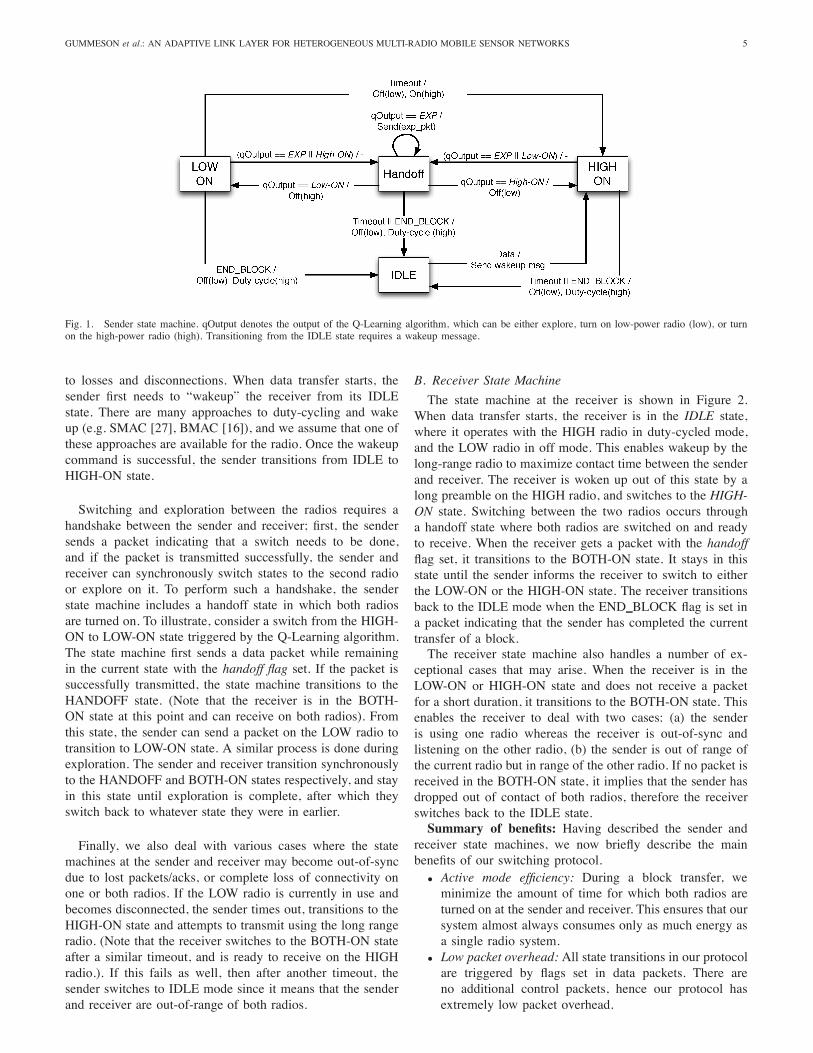
Fig. 1. Sender state machine. qOutput denotes the output of the Q-Learning algorithm, which can be either explore, turn on low-power radio (low), or turnon the high-power radio (high). Transitioning from the IDLE state requires a wakeup message.
to losses and disconnections. When data transfer starts, thesender first needs to “wakeup” the receiver from its IDLEstate. There are many approaches to duty-cycling and wakeup (e.g. SMAC [27], BMAC [16]), and we assume that one ofthese approaches are available for the radio. Once the wakeupcommand is successful, the sender transitions from IDLE toHIGH-ON state.
Switching and exploration between the radios requires ahandshake between the sender and receiver; first, the sendersends a packet indicating that a switch needs to be done,and if the packet is transmitted successfully, the sender andreceiver can synchronously switch states to the second radioor explore on it. To perform such a handshake, the senderstate machine includes a handoff state in which both radiosare turned on. To illustrate, consider a switch from the HIGH-ON to LOW-ON state triggered by the Q-Learning algorithm.The state machine first sends a data packet while remainingin the current state with the handoff flag set. If the packet issuccessfully transmitted, the state machine transitions to theHANDOFF state. (Note that the receiver is in the BOTH-ON state at this point and can receive on both radios). Fromthis state, the sender can send a packet on the LOW radio totransition to LOW-ON state. A similar process is done duringexploration. The sender and receiver transition synchronouslyto the HANDOFF and BOTH-ON states respectively, and stayin this state until exploration is complete, after which theyswitch back to whatever state they were in earlier.
Finally, we also deal with various cases where the statemachines at the sender and receiver may become out-of-syncdue to lost packets/acks, or complete loss of connectivity onone or both radios. If the LOW radio is currently in use andbecomes disconnected, the sender times out, transitions to theHIGH-ON state and attempts to transmit using the long rangeradio. (Note that the receiver switches to the BOTH-ON stateafter a similar timeout, and is ready to receive on the HIGHradio.). If this fails as well, then after another timeout, thesender switches to IDLE mode since it means that the senderand receiver are out-of-range of both radios.
B. Receiver State Machine
The state machine at the receiver is shown in Figure 2.When data transfer starts, the receiver is in the IDLE state,where it operates with the HIGH radio in duty-cycled mode,and the LOW radio in off mode. This enables wakeup by thelong-range radio to maximize contact time between the senderand receiver. The receiver is woken up out of this state by along preamble on the HIGH radio, and switches to the HIGH-ON state. Switching between the two radios occurs througha handoff state where both radios are switched on and readyto receive. When the receiver gets a packet with the handoffflag set, it transitions to the BOTH-ON state. It stays in thisstate until the sender informs the receiver to switch to eitherthe LOW-ON or the HIGH-ON state. The receiver transitionsback to the IDLE mode when the END BLOCK flag is set ina packet indicating that the sender has completed the currenttransfer of a block.The receiver state machine also handles a number of ex-
ceptional cases that may arise. When the receiver is in theLOW-ON or HIGH-ON state and does not receive a packetfor a short duration, it transitions to the BOTH-ON state. Thisenables the receiver to deal with two cases: (a) the senderis using one radio whereas the receiver is out-of-sync andlistening on the other radio, (b) the sender is out of range ofthe current radio but in range of the other radio. If no packet isreceived in the BOTH-ON state, it implies that the sender hasdropped out of contact of both radios, therefore the receiverswitches back to the IDLE state.Summary of benefits: Having described the sender and
receiver state machines, we now briefly describe the mainbenefits of our switching protocol.
• Active mode efficiency: During a block transfer, weminimize the amount of time for which both radios areturned on at the sender and receiver. This ensures that oursystem almost always consumes only as much energy asa single radio system.
• Low packet overhead: All state transitions in our protocolare triggered by flags set in data packets. There areno additional control packets, hence our protocol hasextremely low packet overhead.

6 IEEE JOURNAL ON SELECTED AREAS IN COMMUNICATIONS, VOL. 28, NO. 7, SEPTEMBER 2010
Fig. 2. Receiver state machine
(a) Hardware Prototype (b) Software Architecture
Fig. 3. System Components: (a)Hardware prototype comprising the Tinynodeand a CC2420 expansion board and (b)Unified Link Layer for the radios
• Robustness: Our protocol is robust to channel vagariesand different mobility patterns, and can recover from lostpackets/acks, disconnections, and out-of-sync states.
VI. ARTHROPOD IMPLEMENTATION
We have built a prototype multi-radio platform calledArthropod and have implemented the Q-Learning based adap-tive link-layer and switching protocol. This section describesthe hardware and software implementation of our system.
A. Hardware Architecture
Our Arthropod sensor platform consists of a low-powermicrocontroller and a pair of heterogeneous low-power radios.The current prototype employs a MSP430 microcontroller, aCC2420 radio, and an XE1205 radio. Rather than constructingsuch a platform from scratch, we employed an existing Tinyn-ode sensor platform [6], which contains a MSP430 processorand the XE1205 radio, and augmented it with a custom-builtdaughterboard comprising the CC2420 radio. We constructedthe daughterboard by connecting an EasyBee CC2420 evalua-tion board [19] to several GPIO pins and an SPI bus availableon the Tinynode. Figure 3(a) depicts the resulting prototypehardware of Arthropod.The particular choice of the XE1205 and the CC2420
radios was governed by their complementary characteristics(see Table I). The two radios operating in mutually exclusivefrequency bands—900MHz and the 2.4GHz for the XE1205and CC2420, respectively—enabling better interference adap-tation. The table also shows that when operating at 0 dBm,
both radios yield a range of 80m. However, the energy figuresalso indicate that if 5 or more retransmissions are neededon the CC2420, it is cheaper to use the XE1205 instead. Inpractice, retransmissions are more expensive since the senderneeds to keep the radio active to receive the acknowledgment.Arthropod also enables range diversity. While the peak
range of the XE1205 is 2 kms for a bandwidth setting of1.2 Kbps and +15dBm power level, we were unable to getreliable transmission on the XE1205 at this setting due toknown calibration problems with the TinyNode’s XE1205radio. Therefore, we use a data rate of 38.1 Kbps @+15dBm,at which setting the maximum range is 800m. In contrast,the CC2420 cannot transmit beyond 0dBm and thus has amaximum range of 80m.
B. Software Architecture
The software implementation for Arthropod is an adaptivelink-layer that unifies the individual MAC layers for the tworadios. We have implemented a unified radio interface aspart of the TinyOS-2.x operating system for motes [25]. Theunified radio interface consists of two primary components:TinyOS-2.x drivers for the XE1205 and CC2420 radios and aunified link layer that manages the radio drivers. Figure 3(b)shows the arrangement of these software components. Moreimplementation details may be found in [7].
VII. EXPERIMENTAL EVALUATION
In this section, we present a detailed evaluation of theQ-learning based unified link layer using a combinationof experiments using data traces, results from Q-Learningrunning on an Arthropod mote, as well as implementationbenchmarks. Our evaluation has four parts. First, we evaluatethe performance of the Q-learning link layer in adaptingto a diverse set of mobility patterns. Second, using traceswe evaluate how well the learning algorithm handles powercontrol across the two radio interfaces. Third, we evaluatethe efficacy of Q-learning for handling interference dynamics.Finally, we present benchmarks from an implementation ofthe link layer for an Arthropod mote to demonstrate thatthe described Q-Learning algorithm is efficient and has lowresource usage.
A. Datasets
To ensure repeatable experimentation of the link layer,we gathered datasets under different conditions using our

GUMMESON et al.: AN ADAPTIVE LINK LAYER FOR HETEROGENEOUS MULTI-RADIO MOBILE SENSOR NETWORKS 7
TABLE IIBRIEF SUMMARY OF MOBILITY TRACES.
Environment Mobility Pattern example scenario
urban-indoor continuous w/ obstructions people in a buildingurban-outdoor continuous partial LOS moving vehicleurban-outdoor nomadic bus w/ stops
foliage nomdic bus w/ stops
TABLE IIISUMMARY OF INTERFERENCE TRACES.
Dataset Interference Type Description
Long Interference 30 minute periods indoors; 100ft range;XE1205@0dBm
Medium Interference 200-235 packet bursts indoors; 100ft range;XE1205@0dBm
Short Interference 25-32 packet bursts indoors; 100ft range;XE1205@0dBm
Low Interference ambient indoors; 100ft range;XE1205@0dBm
hardware prototype. We obtained four types of datasets thatare a good representation of mobility patterns found in mobilesensor network deployments. Two of these represent nomadicmovement patterns in urban and rural settings. The othermobility traces gathered represent continuous mobility bothin indoor and outdoor environments. A summary of thesedatasets is presented in Table II. We then gathered fouradditional datasets that represent different types of interferencedynamics. Three of these datasets are created by introducinginterference bursts of varying lengths from other sensor motes.The other dataset consists of ambient interference sourcesfound in typical office buildings (e.g. 802.11, bluetooth).These datasets are briefly desribed in Table III.The datasets were obtained from two Arthropod motes -
one Arthropod mote sends 20 byte packets with increasingsequence numbers over both radio interfaces at a fixed rate(2 Packets / second). A second mote places both radios inreceive mode and acknowledges all packets received on eachradio interface. For each packet, the sending node records thenumber of congestion backoffs experienced while trying tosend the packet, as well as the number of retransmissionsbefore receiving an acknowledgement from the receiver. Themaximum number of backoffs is set to 6, and retransmissionsis set to a limit of 10, after which the link layer at the sendergives up on the transmission.In addition to link layer statistics we also store the radio
chosen by the Q-learning algorithm for each packet. This al-lows us to verify that the algorithm is functioning correctly bycomparing the decisions to the losses seen on each interface.For the mobility datasets, we configure the long-range XE1205radio to a data-rate of 38.1 kbps at 15 dbm, whereas the short-range CC2420 radio uses a data-rate of 250 kbps at 0dbm.
B. Evaluation of Q-Learning for Mobility Dynamics
These experiments evaluate the performance of the Q-learning algorithm in a MATLAB simulation environmentand its performance for the various mobility traces describedabove. To get an accurate measure of the performance ofthe Q-learning based link layer, we emulate the behavior ofthe sender and receiver state machine (Section IV) given thesequence of packet losses observed in the traces. (Later, in
Indoor Continuous Outdoor Bus Outdoor Nomadic Outdoor Habitat0
0.5
1
1.5
2
2.5
3
3.5
mJ
/ Suc
cess
ful P
acke
t
CC2420XE1205Q−Learning
Fig. 4. Energy consumed per successful packet for each dataset and strategy
Indoor Continuous Outdoor Bus Outdoor Nomadic Outdoor Habitat0
10
20
30
40
50
60
70
% P
acke
ts L
ost
CC2420XE1205Q−Learning
Fig. 5. Percent Packets lost for the two radio interfaces and Q-Learningimplementation
Section VII-E we show that this emulation accurately corre-sponds to the performance of the real protocol in practice.)For all datasets, we used an identical set of Q-Learning
parameters: α = 1.0, γ = 0.7 and ε = 0.025. Theseparameters were chosen since they seem to work well acrossa range of mobility datasets.Q-Learning Performance: Figure 4 and Figure 5 sum-
marize the energy per successful packet transmission andloss rates observed by our adaptive multi-radio link layerin comparison with using just one of the radios. In termsof energy consumption, the Q-Learning approach reducesenergy consumption compared to the XE1205 radio by anaverage of 27% (the maximum reduction is 53.6% for theOutdoor Bus dataset), while incurring roughly 2-4% increasedloss across the four cases. The slightly increased loss rateof Q-learning is caused by exploring an alternate interfaceperiodically and transient losses caused while the algorithm isstill learning. Similar energy gains of a maximum of 62.5%and an average of 44.6% are obtained over an approach thatjust uses the CC2420 radio but the improvements in loss rateare significantly higher (25%-60%). The results show that inall cases, the energy consumption of the adaptive multi-radiolink layer is better than exclusively using either the CC2420or XE1205 radio, while keeping the link loss rate to be closeto that observed by the long-range XE1205 radio.As can be seen, the worst case for the Q-Learning protocol
is the outdoor nomadic trace where our benefits are onlymarginal in terms of energy. This is because connectivity usingthe CC2420 radio is highly sporadic and also very lossy (65%loss). Thus, our link layer is unable to take advantage of theCC2420 radio due to the high dynamics on it.In summary, our results show that Q-learning can provide
significant gains in terms of energy while only increasingpacket loss marginally; when an opportunity arises for com-

8 IEEE JOURNAL ON SELECTED AREAS IN COMMUNICATIONS, VOL. 28, NO. 7, SEPTEMBER 2010
TABLE IVSTATISTICS FOR DUAL RADIO / POWER CONTROL TRACE
radio/power-level % packets lost energy consumed
XE1205@0dBm 4.24 .659mJ/Tx SuccessXE1205@15dBm 0 .925mJ/Tx SuccessCC2420@-25dBm 37.01 1.1mJ/Tx SuccessCC2420@0dBm 35.45 1.2mJ/Tx SuccessQ-Learning 3.53 .430mJ/Tx Success
munication over the CC2420 radio interface, our unified linklayer is capable of exploiting its increased energy efficiency.
C. Algorithm performance for power control across radios
A logical extension to the unified link layer is handlingtransmission power control in addition to radio selection. TheCC2420 radio is capable of transmitting packets from -25dBmup to 0dBm, while the XE1205 can transmit from 0dBm to15dBm. Increasing transmit power will provide longer rangeconnectivity but uses additional energy; the optimum strategywill choose the minimum transmit power level on the mostefficient radio without significantly increasing loss rate.To evaluate power control across radio interfaces, we
collected a packet trace similar to the Indoor Continuousdescribed earlier. In addition to logging retransmissions andbackoffs for the XE1205@15dBm and CC2420@0dBm, welog similar statistics for the XE1205 and CC2420@0dBm and-25dBm respectively. The number of states in the Q-Learningalgorithm increases from 2 to 4; we maintain a Q-value foreach radio/power level combination. To reduce explorationoverhead, we only explore the radio/power combinations adja-cent to the current setting. Logically, the next setting expectedfrom a mobile node would be one higher if the distancebetween sender and receiver has increased and one lower if thedistance has decreased. Such an approach would scale even ifthere were more power states being considered per radio.Table IV summarizes the results and compares the Q-
learning approach to just using one of the two radios atone of the power levels. As can be seen, Q-learning is54% better in terms of energy consumption per successfultransmission than only using the XE1205 radio at 15dBmbut has comparable loss rate. The energy benefits over usingthe CC2420 radio are 64%; the loss rate also reduces by anorder of magnitude. Overall, the Q-Learning based adaptivealgorithm sends roughly 40% and 10% of the packets usingXE1205 at 0 dBm and 15 dBm; and 25% of the packets on theCC2520 at -25 dBm and 0 dBm. The results validate that Q-Learning is able to utilize each power state opportunistically.These results show that the unified link layer is very effective
at handling power control across multiple radio interfaces.Our scheme uses 2.5x less power than the highest power radiowith only a negligable packet loss increase. Each setting isused effectively at the appropriate range.
D. Evaluation of Q-Learning for Interference Dynamics
Our next set of experiments evaluate the performance ofthe Q-learning algorithm and its adaptability to changinginterference conditions. Like before, these experiments wereperformed in MATLAB, using the data traces described in theprevious section as input.
Fig. 6. Cumulative energy consumption for Long Bursts of Interference
Fig. 7. Relative performance of Q-Learning for different interferencepatterns: (1) Long, (2) medium, (3) short, (4) low external interference
We compare the Q-learning algorithm against two alternatetechniques. As a baseline, we use an omniscient strategy thathas knowledge of the complete dataset, and is always ableto make an optimal decision regarding which radio should beused. It is important to note that it is impossible for this strat-egy to be realized in practice - it is only used as a baseline togauge how closely Q-Learning performs relative to such a bestcase strategy. The second is a non-adaptive naı̈ve approachthat only looks at the first 100 packets sent across each radiointerface. This approach takes the ratio of cumulative energyconsumption expended by each radio for this set of packets,and determines a probability p, corresponding to the the ratioof energy expended by the CC2420 vs XE1205 radio. Forall other packets, the link layer transmits the packet on theCC2420 radio with probability p, and on the XE1205 radiowith probability 1 − p.Temporal Adaptability: First, we illustrate the adaptabil-
ity of Q-Learning using a time-series plot of the mediuminterference trace, shown in Figure 6. The staircase shapeof the CC2420 and XE1205 radios cumulative energy con-sumption is caused by bursts of interference introduced bythe Telos motes and Tinynodes. The portions of the plotwith a steep slope indicate that the radio is consuming anincreased amount of energy per packet because of congestionand interference. Every time interference is encountered, thiscauses an entry in the Q-Matrix to grow increasingly negativeat a rate determined by the reward r (energy consumption)

GUMMESON et al.: AN ADAPTIVE LINK LAYER FOR HETEROGENEOUS MULTI-RADIO MOBILE SENSOR NETWORKS 9
TABLE VTIME SPENT DURING DIFFERENT RECEIVE STATES
Switching Protocol State % Time SpentHIGH ON 10.7LOW ON 78.1BOTH ON 11.2
and Q-Learning parameters α and γ. Q-Learning settles onthe radio with best channel characteristics, and periodicallyexplores the other radio (ε = 0.01). This gives Q-Learningthe opportunity to adapt when communication patterns changein the network. As a result, the Q-Learning plot represents ahybrid of the CC2420 and XE1205 energy plots, where theradio with a minimum slope is chosen during each burst aftera brief learning period, resulting in a smoothing of energyconsumption over time with consistently better performancethan each individual radio.Aggregate Q-Learning Performance: Figure 7 summa-
rizes how Q-learning performs relative to other schemes acrossall the datasets. For both long and medium term interference,Q-learning performs extremely well compared to choosinga single radio or the multi-radio naı̈ve scheme. For long-term interference, the XE1205 radio consumes 4.2 times moreenergy than our system, the CC2420 consumes 4.8 times moreenergy, and the naı̈ve algorithm consumes 4.5 times moreenergy. For medium time-scale interference, the XE1205 radioalone consumes 5.6 times more energy than is consumed byour algorithm, and the CC2420 radio consumes roughly 1.6times more energy, while the naı̈ve two-radio algorithm alsouses around 1.6 times more energy. The gains are intuitivesince the naı̈ve algorithm is non-adaptive and assumes that thebehavior across the first 100 packets will be representative offuture channel conditions. The Q-learning algorithm, however,is not as efficient as the omniscient approach which consumes77% of the energy used by Q-Learning in the case of long-terminterference and 69% of the energy used by Q-Learning in thecase of short-term interference. This is because the omniscientalgorithm wastes no energy exploring the two channels andalso is never impacted by channel dynamics.The short interference trace represents a case where Q-
learning can be expected to perform badly since the channelis switching behavior every 30 packets. When we choose theexploration factor, ε, to be small, it is difficult to learn withfew samples that the current radio-channel has become poorand the other radio channel has improved from its previousstate. When undersampling the channel in this manner, thelearning algorithm eventually converges on following the radiothat uses less overall energy, but does not make improvementsbeyond the better of the two radios. The low interferencetrace represents a scenario where the environment has limiteddynamics since there is very little external interference. Forthis scenario, our Q-Learning algorithm will choose the moreenergy-efficient radio (CC2420) and encounter a slight amountof overhead as a result of exploring the more energy-expensivechannel periodically. In both these cases, Q-learning is almostas efficient as choosing the best radio.In summary, our results show that Q-learning can provide
significant performance gains when there is medium and
XE1205 CC2420 Dual Radio0
0.5
1
1.5
2
mJ
/ Suc
cess
ful T
rans
mis
sion
Loss=(0.6%)
Loss=(43.0%)
Loss=(1.4%)
(a) Sender
XE1205 CC2420 Dual Radio0
100
200
300
uJ /
Suc
cess
ful R
ecep
tion
(b) Receiver
Fig. 8. Energy spent per packet by the sender and receiver. Labels on senderbars indicate packet loss rates.
long term interference that is greater than 200 packets inlength. Even in hard to learn conditions such as short burstsof interference, and low interference conditions with limiteddynamics, Q-Learning performs only marginally worse thanthe better of the two radios.
E. Implementation Results
To validate our implementation and show the performanceof the radio switching protocol, we collect a new dataset withthe same mobility pattern as the indoor continuous dataset.For this experiment, a pair of sender and receiver nodesrun the switching protocol and Q-Learning algorithm online.This study aims to measure the actual per packet energycosts incurred by the sender and receiver. In particular, thereceiver can become out-of-sync with the sender, resulting inthe receiver turning both radios on, or timing out, all of whichcosts energy and results in more packet losses. For the mobilityrates used in our experiments we chose a timeout value of 2seconds. Finally, we also breakdown the % time spent by thereceiver in different states of the receiver state machine.The maximum data rate achievable by our software im-
plementation for a pair of nodes transmitting continuouslyis 70kbps. However, while logging packet statistics to theexternal flash, the data rate reduces to 14kbps. This lowerdata rate is a result of the Tinynode platform multiplexingthe SPI bus between the XE1205 radio and the externalflash memory. As a result, the sender and receiver are notcontinuously sending data which causes idle gaps to appearbetween packets. This forces the receiver to expend additionalenergy while waiting for packets to arrive. Since the idle timeis an artifact of our evaluation, we ignore these periods whenpresenting results.To understand the energy efficiency of our protocol at the
sender, Figure 8(a) compares the energy consumed by a single

10 IEEE JOURNAL ON SELECTED AREAS IN COMMUNICATIONS, VOL. 28, NO. 7, SEPTEMBER 2010
TABLE VILATENCY AND ENERGY CONSUMPTION FOR LINK-LAYER COMPONENTS
Task Latency Energy
Radio Selection 19.3us 104nJQ-Matrix Update 43.6us 235nJTransmit 20-Byte packet (XE1205 @ 0dBmand 76.8kbps)
3.9ms 218uJ
Transmit 20-Byte packet (CC2420 @ 0dBm) 1.7ms 92uJ
radio strategy to that of the dual radio implementation. The perpacket energy consumption numbers presented for the CC2420and XE1205 only cases are from Section VII-B. The resultsin Figure 8(a) show that our adaptive algorithm is 64% moreefficient than a CC2420-only scheme, and 43% more efficientthan an XE1205-only scheme verifying the gains found insimulation. These energy efficiency gains are achieved whilemaintaining a loss rate of 1.6% which is not substantiallyhigher than the XE1205 loss rate of 0.6% and much lowerthan the 43.0% loss rate of the CC2420 radio. These resultsvalidate our simulation study and show that substantial sender-side energy gains are acheivable by opportunistically using theCC2420 radio, while providing a loss rate comparable to thatof the XE1205 radio.Figure 8(b) shows the amount of energy consumed at the
receiver as a result of the decisions made by the sender.The energy efficiency of the receiver will always fall some-where between the efficiency of the XE1205 and CC2420radios, depending on how often each is used. Bringing upboth radio interfaces is an unavoidable result of the radioswitching protocol and represents overhead beyond that ofa single radio strategy. Additionally, transition times fromsleep to idle/receive mode represent overhead. Our evaluationshows that the dual-radio protocol used 70% less energy thanthe XE1205, but 13% more energy than the CC2420. It isimportant to note that the receiver uses an order of magnitudeless power than the sender, which means the sender-side gainsovershadow the receiver-side losses.Finally, we provide a breakdown of the percentage of
packets the receiver spends in each state of the switchingprotocol in Table V. The receiver spends 10.7% of time inthe HIGH-ON state, 78.1% of time in the LOW-ON stateand 11.2% of time in the BOTH-ON state. Ideally the radioswitching protocol will only force the receiver into the BOTH-ON state while exploring or handing off between radios.Exploration accounts for 4% of this time, while the other 7.2%is caused by explicit handoffs and timeouts.
F. Microbenchmarks
In this section, we briefly discuss measurement-based la-tency and energy consumption microbenchmarks based on ourimplementation of the unified link layer. As shown in Table VI,the energy/latency overhead imposed on the CPU by our multi-radio adaptation algorithm implementation on the Arthropodis highly efficient and consumes less than a hundredth ofthe energy/latency of the radios used. This shows that theoverhead introduced by software can be compensated by largerperformance gains achieved through intelligent radio selection.The amount of memory overhead of our implementation is111 bytes, which is a very small portion of the available
TABLE VIIDRIVER PERFORMANCE FOR MAC LAYER OPERATIONS
XE1205 Radio CC2420 Radio
Ack RTT 1.79ms 1.04msAck Timeout 2.6ms 2.4ms
Avg. Congestion Backoff 10.4ms 10.4msChannel Sense Time 1.6ms .756ms
Sleep to Active Mode Transition Time 1.5ms 0.58ms
Fig. 9. Cumulative energy performance increase for different parametervalues
10kB. A much larger portion of program memory is required,however, because two radio stacks need to be instantiated;supporting an additional radio stack requires an additional12kB resulting in a total usage of 29kB out of the available48kB of program memory, although we believe that this canbe optimized considerably.We also micro-benchmarked MAC layer operations in our
TinyOS drivers. Table VII shows the individual componentsbased on which the reward matrix is populated as describedin Section IV. These measurements were used to computethe total energy cost of a transmitted packet and account foroverheads in the state transitions of a receiver.
G. Parameter Sensitivity
In this section we study the sensitivity of Q-learning toits parameters: α, γ and ε. To demonstrate the algorithm’srobustness to parameter variation, we use our mobility datasetto show how the total energy consumption of the Q-Learningalgorithm changes with respect to changes in parameter values.Figure 9 shows a number of plots, where for each plot we fix αand vary γ. The plots are very similar across several differentα values and demonstrate that as long as α and γ are chosenwithin a reasonable range, the performance of Q-Learning isstable. We repeated this procedure for the interference datasets,and found similar results.Overall, we have found that a larger α value is generally
helpful in mobility traces due to the need for fast switching.As the traces become more nomadic in nature (i.e. as theyinvolve more waiting and less movement), the optimal choiceof α reduces a little. However, 0.9 ≤ α ≤ 1 seems to be idealin almost all settings. The choice of ε impacts how fast we canswitch but it also impacts the energy consumption. A high εcan lead to more exploration overhead but is more reactive. Wefound that exploration roughly every 10 seconds or so provides

GUMMESON et al.: AN ADAPTIVE LINK LAYER FOR HETEROGENEOUS MULTI-RADIO MOBILE SENSOR NETWORKS 11
a good balance but this can be tuned depending on expecteddynamics. Finally, we found that the results were not verysensitive to γ, and works best in the range 0.5 ≤ γ ≤ 0.85.
VIII. CONCLUSIONS
In conclusion, we have made three major contributionsin this paper. First, we designed a new multi-radio sensorplatform, the Arthropod, that pairs two radios - CC2420 andXE1205 - that offer diversity in frequency, power and range.Second, we presented the design of a Q-Learning-driven adap-tive link layer that provides the abstraction of a single radioto the applications, and third, we presented a protocol thatswitches between radios depending on which radio offers themost energy-efficient communication channel. Experimentsusing a number of interference and distance datasets confirmthat the system can provide effective adaptation to a range ofdynamics. We also showed that the learning algorithm can beeasily implemented with limited memory and computationaloverhead on a mote-class sensor platform.
REFERENCES
[1] Y. Agarwal, R. Chandra, A. Wolman, V. Bahl, K. Chin, and R. Gupta.Wireless wakeups revisited: Energy management for voip over wi-fismartphones. In Proc. Mobisys, Puerto Rico, USA, June 2007.
[2] N. Banerjee, M. D. Corner, and B. N. Levine. An Energy-EfficientArchitecture for DTN Throwboxes. In Proc. IEEE Infocom, May 2007.
[3] N. Banerjee, J. Sorber, M. D. Corner, S. Rollins, and D. Ganesan. Triage:A Power-Aware Software Architecture for Tiered Microservers. In Proc.Mobisys, Puerto Rico, USA, June 2007.
[4] J. Burgess, B. Gallagher, D. Jensen, and B. N. Levine. MaxProp:Routing for Vehicle-Based Disruption-Tolerant Networks. In Proc. IEEEINFOCOM, April 2006.
[5] R. Draves, J. Padhye, and B. Zill. Routing in multi-radio, multi-hopwireless mesh networks. In Proc. ACM MobiCom, pages 114–128,Philadelphia, PA, September 2004.
[6] H. Dubois-Ferrire, R. Meier, L. Fabre, and P. Metrailler. TinyNode: AComprehensive Platform for Wireless Sensor Network Applications. InInformation Processing in Sensor Networks (IPSN 2006), 2006.
[7] J. Gummeson, D. Ganesan, M. D. Corner, and P. Shenoy. An adaptivelink layer for heterogeneous multi-radio mobile sensor networks. Tech-nical Report UM-CS-2010-013, University of Massachusetts, 2010.
[8] H.-Y. Hsieh and R. Sivakumar. A transport layer approach for achievingaggregate bandwidths on multi-homed mobile hosts. In Proc. ACMMobicom, Atlanta, GA, September 2002.
[9] P. Juang, H. Oki, Y. Wang, M. Martonosi, L. Peh, and D. Rubenstein.Energy-efficient computing for wildlife tracking: Design tradeoffs andearly experiences with zebranet. In ASPLOS, San Jose, CA, October2002.
[10] H. Jun, M. H. Ammar, M. D. Corner, and E. Zegura. HierarchicalPower Management in Disruption Tolerant Networks with Traffic-AwareOptimization. In Proc. ACM SIGCOMM Workshop on ChallengedNetworks (CHANTS), September 2006.
[11] D. Lymberopoulos, B. Priyantha, M. Goraczko, and F. Zhao. Towardsenergy efficient design of multi-radio platforms for wireless sensornetworks. In Proc. of IPSN, St. Louis, MO, April 2008.
[12] N. Mishra, K. Chebrolu, B. Raman, and A. Pathak. Wake-on-WLAN. InProc. Intl Conf on the World Wide Web (WWW), pages 761–769, 2006.
[13] V. Navda, A. P. Subramanian, K. Dhanasekaran, A. Timm-Giel, andS. Das. Mobisteer: using steerable beam directional antenna forvehicular network access. In MobiSys, New York, NY, USA, 2007.
[14] T. Pering, Y. Agarwal, R. Gupta, and R. Want. CoolSpots: Reducing thePower Consumption of Wireless Mobile Devices with Multiple RadioInterfaces. In Proc. ACM MobiSys, pages 220–232, June 2006.
[15] T. Pering, V. Raghunathan, and R. Want. Exploiting Radio Hierarchiesfor Power-Efficient Wireless Device Discovery and Connection Setup.In VLSI Design, pages 774–779, 2005.
[16] J. Polastre, J. Hill, and D. Culler. Versatile low power media accessfor wireless sensor networks. In Proc. Second ACM Conference onEmbedded Networked Sensor Systems (SenSys), November 2004.
[17] A. Rahmati and L. Zhong. Context-for-wireless: Context-sensitiveenergy-efficient wireless data transfer. In Proc.Mobisys, Puerto Rico,USA, June 2007.
[18] J. Redi, S. Solek, K. Manning, C. Partridge, R. Rosales-Hain, R. Ra-manathan, and I. Castineyra. Javelen - an ultra-low energy ad hocwireless network. In Ad Hoc Networks, Vol. 6, No. 1, January 2008.
[19] http://www.rfsolutions.co.uk. RF Solutions: EasyBee ZigbeeTransceiver.
[20] P. Rodriguez, R. Chakravorty, J. Chesterfield, I. Pratt, and S. Banerjee.Mar: A commuter router infrastructure for the mobile internet. In Proc.Second International Conference on Mobile Systems, Applications, andServices, Boston, MA, June 2004.
[21] C. Sengul, A. Harris, M. Bakht, T. Abdelzaher, and R. Kravets.Improving energy conservation using bulk transmission over high-powerradios in sensor networks. In Proc. ICDCS, Beijing, China, June 2008.
[22] E. Shih, P. Bahl, and M. J. Sinclair. Wake on Wireless: An eventdriven energy saving strategy for battery operated devices. In Proc.ACM MobiCom, Atlanta, GA, September 2002.
[23] T. Stathopoulos, M. Lukac, D. McIntire, J. Heidemann, D. Estrin, andW. Kaiser. End-to-end routing for dual-radio sensor networks. In Proc.IEEE Infocom 2007, Anchorage, Alaska, USA, May 2007.
[24] R. S. Sutton and A. G. Barto. Reinforcement Learning: An Introduction.The MIT Press, 1998.
[25] TinyOS Website. http://www.tinyos.net/.[26] http://www.maxstream.com. XTend OEM RF Module for Long-range
Data Transfer.[27] W. Ye, J. Heidemann, and D. Estrin. An energy-efficient mac protocol
for wireless sensor networks. In Proc. IEEE INFOCOM, pages 1567–1576, New York, NY, USA, June 2002.
[28] J. Zhu, A. Waltho, X. Yang, and X. Guo. Multi-radio coexistence:Challenges and opportunities. In Proc. ICCCN, August 2007.
Jeremy Gummeson Jeremy Gummeson is currentlya PhD student in the Department of Electrical Engi-neering at the University of Massachusetts Amherst.He received his B.S and M.S. Degrees from theUniversity of Massachusetts Amherst in 2006 and2010, respectively. His research interests are inSensor Networks, Energy Harvesting, and RFID.
Deepak Ganesan Deepak Ganesan is currently As-sistant Professor in the Department of ComputerScience at UMASS Amherst. He received his Ph.D.in Computer Science from UCLA in 2004 and hisbachelors in Computer Science from IIT, Madrasin 1998. He received the NSF CAREER Award in2006 and the IBM Faculty Award in 2008. He wasselected as a UMass Junior Faculty Fellow in 2008,and a UMass Lilly Teaching Fellow in 2009. He isa Program co-chair for ACM SenSys 2010.
Mark Corner Mark Corner has been an AssociateProfessor in the Department of Computer Scienceat the University of Massachusetts Amherst since2003. He graduated with his PhD in ElectricalEngineering from the University of Michigan. Hisinterests are in mobile and pervasive computing andnetworking, file systems, and security. He receivedan NSF CAREER award in 2005, Best Paper Awardsat FAST 2007 and ACM Multimedia 2005, andthe Best Student Paper Award at Mobicom 2002.Prof. Corner serves on the editorial board of IEEE
Pervasive.

12 IEEE JOURNAL ON SELECTED AREAS IN COMMUNICATIONS, VOL. 28, NO. 7, SEPTEMBER 2010
Prashant Shenoy Prashant Shenoy received theB.Tech degree in Computer Science and Engineeringfrom the Indian Institute of Technology, Bombayin 1993, and the M.S and Ph.D degrees in Com-puter Science from the University of Texas, Austin,in 1994 and 1998, respectively. He is currently aProfessor of Computer Science at the University ofMassachusetts Amherst.His research interests are in operating and dis-
tributed systems, sensor networks, Internet systemsand pervasive multimedia. He has been the recipient
of the National Science Foundation Career Award, the IBM Faculty Devel-opment Award, the Lilly Foundation Teaching Fellowship, the UT ComputerScience Best Dissertation Award, an IIT Silver Medal, and best paper awardsat USENIX, ACM Multimedia and IEEE WISE. He is a senior member ofthe IEEE and a distinguished member of the ACM.