ieee internet of things journal, vol. 1, no. 1,...
TRANSCRIPT
Time-Reversal Wireless Paradigm for GreenInternet of Things: An Overview
Yan Chen, Member, IEEE, Feng Han, Member, IEEE, Yu-Han Yang, Student Member, IEEE, Hang Ma, Yi Han,Chunxiao Jiang, Member, IEEE, Hung-Quoc Lai, Member, IEEE, David Claffey, Zoltan Safar, and
K. J. Ray Liu, Fellow, IEEE
Abstract—In this paper, we present an overview of the time-reversal (TR) wireless paradigm for green Internet of Things (IoT).It is shown that the TR technique is a promising technique thatfocuses signal waves in both time and space domains. The uniqueasymmetric architecture significantly reduces the cost of the terminaldevices, the total number ofwhich is expected tobevery large for IoT.The focusing effect of the TR technique can harvest the energy of allthe multi-paths at the receiver, which improves the energy efficiencyof the wireless transmission and thus the battery life of terminaldevices in IoT. Facilitated by the high-resolution spatial focusing, theTR division multiple access scheme leverages the uniqueness of themulti-path profiles in the rich-scattering environment and mapsthem into location-specific signatures, so that spatial multiplexingcan be achieved for multiple users operating on the same spectrum.Inaddition, theTRsystemcaneasily support heterogeneous terminaldevices by providing various quality-of-service (QoS) optionsthrough adjusting the waveform and rate backoff factor. Finally,the unique location-specific signature in TR system can provideadditional physical-layer security and thus can enhance the privacyand security of customers in IoT.All the advantages show that theTRtechnique is a promising paradigm for IoT.
Index Terms—Internet of Things (IoT), spatial focusing,temporal focusing, time reversal (TR), time-reversal divisionmultiple access (TRDMA).
I. INTRODUCTION
D URING the past decade, the Internet of Things (IoT) hasdrawn great attention from both academia and industry,
since it offers challenging notion of creating aworldwhere all the
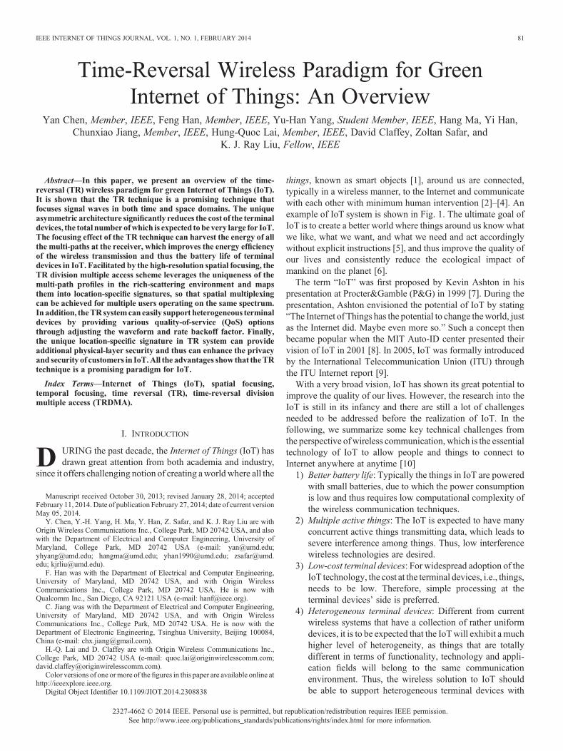
things, known as smart objects [1], around us are connected,typically in a wireless manner, to the Internet and communicatewith each other with minimum human intervention [2]–[4]. Anexample of IoT system is shown in Fig. 1. The ultimate goal ofIoT is to create a better world where things around us know whatwe like, what we want, and what we need and act accordinglywithout explicit instructions [5], and thus improve the quality ofour lives and consistently reduce the ecological impact ofmankind on the planet [6].
The term “IoT” was first proposed by Kevin Ashton in hispresentation at Procter&Gamble (P&G) in 1999 [7]. During thepresentation, Ashton envisioned the potential of IoT by stating“The Internet of Things has the potential to change theworld, justas the Internet did. Maybe even more so.” Such a concept thenbecame popular when the MIT Auto-ID center presented theirvision of IoT in 2001 [8]. In 2005, IoT was formally introducedby the International Telecommunication Union (ITU) throughthe ITU Internet report [9].
With a very broad vision, IoT has shown its great potential toimprove the quality of our lives. However, the research into theIoT is still in its infancy and there are still a lot of challengesneeded to be addressed before the realization of IoT. In thefollowing, we summarize some key technical challenges fromthe perspective ofwireless communication, which is the essentialtechnology of IoT to allow people and things to connect toInternet anywhere at anytime [10]
1) Better battery life: Typically the things in IoT are poweredwith small batteries, due to which the power consumptionis low and thus requires low computational complexity ofthe wireless communication techniques.
2) Multiple active things: The IoT is expected to have manyconcurrent active things transmitting data, which leads tosevere interference among things. Thus, low interferencewireless technologies are desired.
3) Low-cost terminal devices: For widespread adoption of theIoT technology, the cost at the terminal devices, i.e., things,needs to be low. Therefore, simple processing at theterminal devices’ side is preferred.
4) Heterogeneous terminal devices: Different from currentwireless systems that have a collection of rather uniformdevices, it is to be expected that the IoTwill exhibit a muchhigher level of heterogeneity, as things that are totallydifferent in terms of functionality, technology and appli-cation fields will belong to the same communicationenvironment. Thus, the wireless solution to IoT shouldbe able to support heterogeneous terminal devices with
Manuscript received October 30, 2013; revised January 28, 2014; acceptedFebruary 11, 2014. Date of publication February 27, 2014; date of current versionMay 05, 2014.
Y. Chen, Y.-H. Yang, H. Ma, Y. Han, Z. Safar, and K. J. Ray Liu are withOrigin Wireless Communications Inc., College Park, MD 20742 USA, and alsowith the Department of Electrical and Computer Engineering, University ofMaryland, College Park, MD 20742 USA (e-mail: [email protected];[email protected]; [email protected]; [email protected]; [email protected]; [email protected]).
F. Han was with the Department of Electrical and Computer Engineering,University of Maryland, MD 20742 USA, and with Origin WirelessCommunications Inc., College Park, MD 20742 USA. He is now withQualcomm Inc., San Diego, CA 92121 USA (e-mail: [email protected]).
C. Jiang was with the Department of Electrical and Computer Engineering,University of Maryland, MD 20742 USA, and with Origin WirelessCommunications Inc., College Park, MD 20742 USA. He is now with theDepartment of Electronic Engineering, Tsinghua University, Beijing 100084,China (e-mail: [email protected]).
H.-Q. Lai and D. Claffey are with Origin Wireless Communications Inc.,College Park, MD 20742 USA (e-mail: [email protected];[email protected]).
Color versions of one ormore of the figures in this paper are available online athttp://ieeexplore.ieee.org.
Digital Object Identifier 10.1109/JIOT.2014.2308838
IEEE INTERNET OF THINGS JOURNAL, VOL. 1, NO. 1, FEBRUARY 2014 81
2327-4662 © 2014 IEEE. Personal use is permitted, but republication/redistribution requires IEEE permission.See http://www.ieee.org/publications_standards/publications/rights/index.html for more information.
different quality-of-service (QoS) options such as fromvery low bit rate to very high.
5) Scalability: The density of the things in IoT may be veryhigh or low, which requires the wireless technology to behighly scalable to provide satisfactory QoS for low to highdensity areas.
6) Privacy and security: Since every thing in IoT has a uniqueidentification, there is a need to have a technically soundsolution to guarantee privacy and the security of thecustomers in order to have a widespread adoption of IoT.
Toqualify as a goodwireless communication solution to IoT, atechnology should be able to handle the challenges raised above.Currently existing wireless technologies for IoT can be classifiedinto two groups: 1) wireless technologies for low-data-rate andlow-power applications such as remote control [11], [12]; and2) wireless technologies for high-data-rate applications such asvideo streaming [13]–[17]. Note that the technologies suitablefor low-data-rate applications may not be able to meet therequirements of the high-data-rate applications.
A typical wireless communication technology suitable for lowpower, low-data-rate applications is ZigBee [11]. Mainly basedon IEEE802.15.4, ZigBee canoperate in the 868MHz, 915MHz,and 2.4 GHz bands with respective data rates of 20, 40, and250 kb/s. A similar technology is Z-Wave [12], whose mainpurpose is to enable short message transmission from a controlnode to multiple nodes. The maximum speed of Z-Wave is
200 kb/s working at 2.4-GHz band. The most significant advan-tage of ZigBee and Z-Wave is the low price [18], [19]. Forinstance, there exist chips including RF module, thedigital baseband module, and a programmable microcontroller.Both of these technologies were designed for low-power appli-cations in battery-operated devices. Moreover, ZigBee evenincludes a sleep-modemechanism to reduce power consumption.The complexity of hardware is quite low: 32–128 kbytes ofmemory is enough to implement the system including the higherlayers. On the other hand, the most obvious disadvantage ofZigBee and Z-Wave is their low data rate. Moreover, the 2.4-GHz frequency band is already crowdedwith interfering devices,e.g., microwave ovens, WiFi equipment, and cordless phones.The sub-GHz electromagnetic (EM)waves propagate very far, sovery high node density may not be achievable due to the highinterference levels created by other similar devices.
The most popular technologies for high-data-rate applicationsare Bluetooth [13] and WiFi [14]. Bluetooth, based on IEEE802.15.1, is a wireless technology for exchanging data over shortdistance. Comparedwith ZigBee andZ-Wave, the data rate couldbe increased tomegabit per second (Mbps).WiFi, based on IEEE802.11, is a popular technology that allows an electronic deviceto exchange data or connect to the Internet wirelessly. The speedof WiFi can achieve up to several gigabit per second (Gbps)according to IEEE 802.11ac with the help of MIMO and veryhigh-order modulation. The most important advantage of these
Fig. 1. Illustration of TR system for IoT.
82 IEEE INTERNET OF THINGS JOURNAL, VOL. 1, NO. 1, FEBRUARY 2014
two technologies is the high data rate. However, they requirehigher power consumption, higher complexity of hardware(MIMO in WiFi) and thus higher price [20]. Since both trans-mitter and receiver use the same architecture, i.e., symmetricarchitecture is used, the power consumption of terminal devicesis high. In addition, a large number of WiFi access points (APs)deployed close to each other operating in the same or adjacentchannels will severely interfere with each other. Thus, thesetechnologies do not seem to offer robust performance in inter-ference-limited scenarios even with costly terminal devices.Another possible technology is the 3G/4G mobile communica-tions [21]–[23]. However, the poor indoor coverage of 3G/4Gsignals greatly limit its application to IoT, where communica-tions mostly happen in indoor environment.
From the above discussions, we can see that existing technolo-gies can only address partial challenges while leaving the restunaddressed, e.g., both the heterogeneity andscalability challengescannot be handled by existing technologies. A natural question toask is: is there awireless communication technique that can addressmost, if not all, challenges? As pointed out in [24], time-reversal(TR) signal transmission is an ideal paradigm for low-complexity,low energy consumption green wireless communication becauseof its inherent nature to fully harvest energy from the surroundingenvironment by exploiting the multi-path propagation to recollectall the signal energy that could be collected as the ideal RAKEreceiver. The theoretic analysis in [24] shows that a typical TRsystemhas a potential of over anorder ofmagnitudeof reduction inpower consumption and interference alleviation, whichmeans thatTR system can provide better battery life and support multipleconcurrent active users. Moreover, with our proposed asymmetricTR architecture, only one-tap detection is needed at the receiverside [25], thus the computational complexity at the terminaldevices is low, which means the cost of the terminal devices isalso low. Note that the achievable rate can still be very high whenthe bandwidth iswide enough as shown in [26]. In addition, the TRsystem can easily support heterogeneous terminal devices byproviding various QoS options through adjusting the waveformand backoff factor [25], [27]. Finally, the unique location-specificsignature in TR system can provide additional physical-layersecurity and thus can enhance the privacy and security of custo-mers in IoT [24].Overall,wewill provide anoverview to show thatTR technique is an ideal paradigm for IoT.
The rest of the paper is organized as follows. In Section II, weintroduce some basic concepts of TR technique. Then, we proposeinSection III anasymmetricTRdivisionmultiple access (TRDMA)architecture and discuss in details why TR is an ideal paradigm forIoT. In Section IV, we discuss other challenging issues and futuredirections includingadvancedwaveformdesign,MAClayer issues,and low-cost high-speed analog-to-digital converter (ADC) andDAC. Finally, we draw conclusions in Section V.
II. SOME BASICS OF TR
A. The Basic Principles of TR
The TR signal processing is a technology to focus the power ofsignal waves in both time and space domains. The research of TRcan date back to early 1970s, when phase conjugation was firstobserved and studied by Zeldovich et al. [28]. Unlike the phase
conjugation that uses an holographic or parametric pumping[29], the TR uses transducers to record the signal waves andenables signal processing on the recorded waveforms.
The TR signal processing was applied by Fink et al. in 1989[30], followed by a series of theoretical and experimental worksin acoustic communications [31]–[38]. As found in acousticphysics [30]–[34] and then further validated in practical under-water propagation environments [35]–[37], the energy of the TRacoustic waves from transmitters could be refocused only at theintended location with very high spatial resolution. Since TR canmake full use of multi-path propagation and also requires nocomplicated channel processing and equalization, it was laterverified and tested in wireless radio communication systems.Experimental validations of TR technique with EM waves havebeen conducted in [24], [39]–[45], including the demonstrationof spatial and temporal focusing properties [24], [39]–[45] andchannel reciprocity [24], [41]. The feasibility of applying TRtechnique into ultra-wideband (UWB) communications has beenstudied in [46]–[48] with the focus on the bit error rate (BER)performance through simulation. A system-level theoreticalinvestigation and comprehensive performance analysis of aTR-based multiuser communication system was conducted in[25], where the concept of TRDMA was proposed. To improvethe performance of the TRDMA systems, interference suppres-sion through waveform design [27], [49] and interference can-celation [50] are proposed. The implementation complexity issueis studied in [26], [51], and [52]. Moreover, as shown in [53],[54], with random scatterers, TR can achieve focusing that is farbeyond the diffraction limit, i.e., half wavelength.
The principle of TR transmission is very simple, as demon-strated in Fig. 2. In this figure, when transceiver A wants totransmit information to transceiver B, transceiver B first has tosend an impulse-like pilot signal that propagates through ascattering and multi-path environment and the resulting wave-forms are received and recorded by transceiver A. This is calledchannel probing phase. After that, transceiver A simply time-reverses (and conjugated, if the signal is complex valued) thereceived waveform and then transmits it back through the samechannel to transceiver B. This is called TR-transmission phase.
There are two basic assumptions for the TR communicationsystem to work.
1) Channel reciprocity: the impulse responses of the forwardlink channel and the backward link channel are assumed tobe identical.
2) Channel stationarity: the channel impulse responses(CIRs) are assumed to be stationary for at least oneprobing-and-transmitting cycle.
Fig. 2. Time reversal signal processing principle.
CHEN et al.: TR WIRELESS PARADIGM FOR GREEN IoT 83
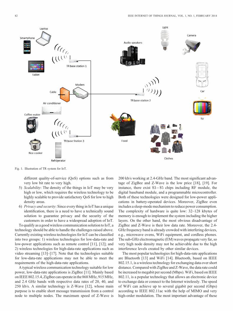
These two assumptions generally hold in reality, especially forindoor environment, as validated through real experiments in[55] and [24]. In [55], Qiu et al. conducted experiments in acampus lab area and showed that the correlation between theimpulse response of the forward link channel and that of back-ward link channel is as high as about 0.98, which means that thechannel is highly reciprocal. In [24], Wang et al. showed withexperimental results that the multi-path channel of an officeenvironment is actually not changing a lot. In their experiment,Want et al.measured the channel information every one minute,and a total of 40 channel snapshots were taken and stored, wherethe first 20 snapshots correspond to a static environment, snap-shots 21 to 30 correspond to a moderately varying environment,and snapshots 31 to 40 correspond to a varying environment. Theexperimental results are shown in Fig. 3, where we can see thatmost the correlation coefficients between different snapshots arehigher than 0.8 and those between static snapshots are above0.95, which means that the channel is highly stationary.
By utilizing channel reciprocity, the re-emitted TR waves canretrace the incoming paths, ending up with a constructive sum ofsignals of all the paths at the intended location and a “spiky”signal-power distribution over the space, as commonly referredto as spatial focusing effect. Also from the signal processingpoint of view, in the point-to-point communications, TR essen-tially leverages the multi-path channel as a matched filter andfocuses the wave in the time domain as well, as commonlyreferred as temporal focusing effect. By treating the environmentas a facilitating matched filter computing machine, the complex-ity of TR systems is significantly reduced, which is ideal for IoTapplications as we will discuss later.
B. Temporal Focusing and Spatial Focusing of TR
In principle, the mechanisms of reflection, diffraction, andscattering in wireless medium give rise to the uniqueness andindependence of the CIR of each multi-path communication link[56]. Obtained from real indoor experiments [24], Figs. 4 and 5show that, when the re-emitted TR waves from transceiver Apropagate in thewirelessmedium, the location of transceiver B is
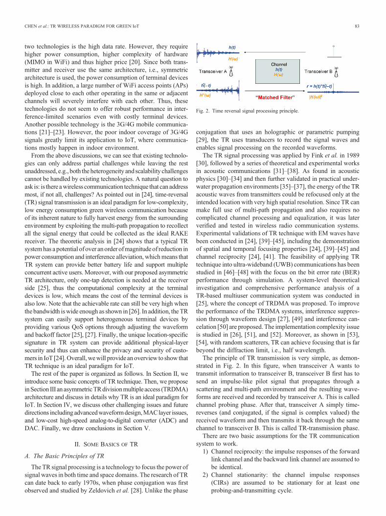
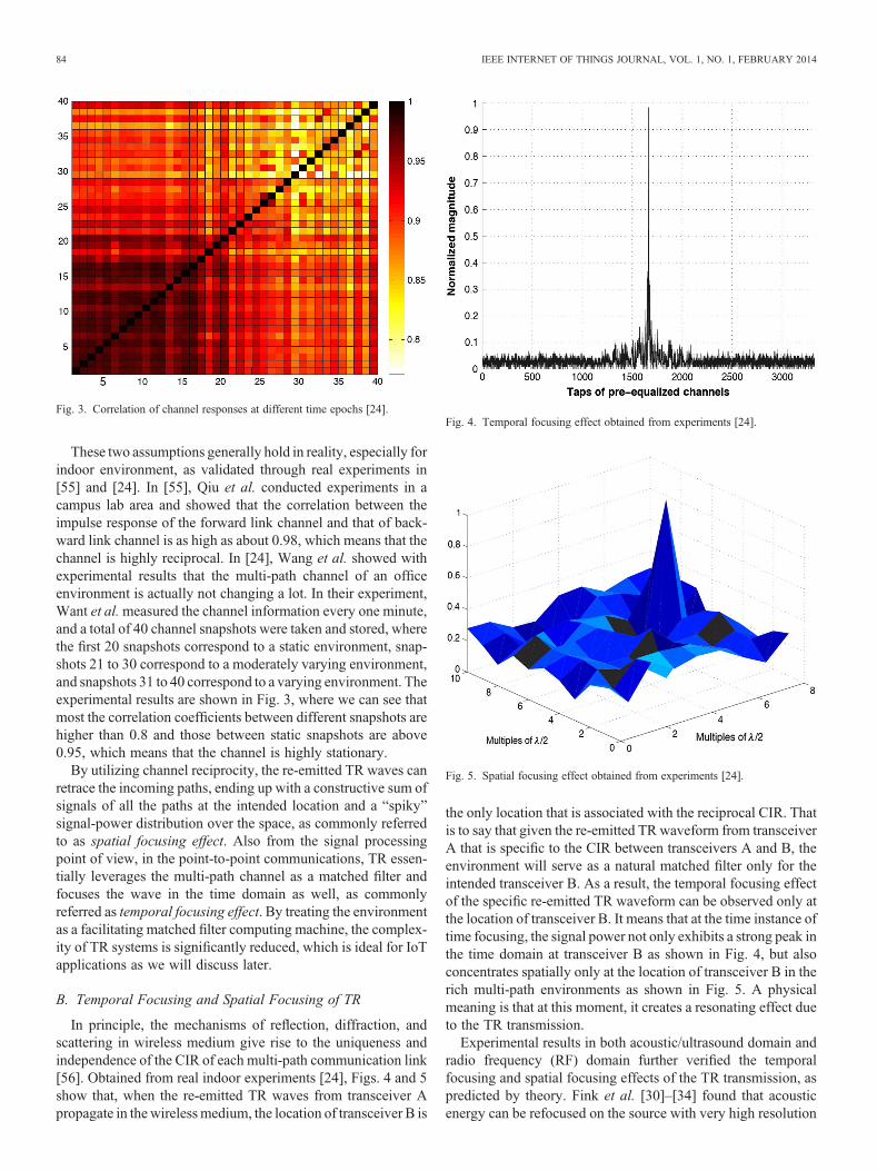
the only location that is associated with the reciprocal CIR. Thatis to say that given the re-emitted TR waveform from transceiverA that is specific to the CIR between transceivers A and B, theenvironment will serve as a natural matched filter only for theintended transceiver B. As a result, the temporal focusing effectof the specific re-emitted TR waveform can be observed only atthe location of transceiver B. It means that at the time instance oftime focusing, the signal power not only exhibits a strong peak inthe time domain at transceiver B as shown in Fig. 4, but alsoconcentrates spatially only at the location of transceiver B in therich multi-path environments as shown in Fig. 5. A physicalmeaning is that at this moment, it creates a resonating effect dueto the TR transmission.
Experimental results in both acoustic/ultrasound domain andradio frequency (RF) domain further verified the temporalfocusing and spatial focusing effects of the TR transmission, aspredicted by theory. Fink et al. [30]–[34] found that acousticenergy can be refocused on the source with very high resolution
Fig. 4. Temporal focusing effect obtained from experiments [24].Fig. 3. Correlation of channel responses at different time epochs [24].
Fig. 5. Spatial focusing effect obtained from experiments [24].
84 IEEE INTERNET OF THINGS JOURNAL, VOL. 1, NO. 1, FEBRUARY 2014

(wavelength level). In [35]–[37], acoustics experiments in theocean were conducted to validate the focusing effects of TR inreal underwater propagation environments. In the RF domain,experiments in [39], [40], and [46] demonstrated the spatial andtemporal focusing properties of EM signal transmission with TRby taking measurements in RF communications. Furthermore, aTR-based interference canceler to mitigate the effect of clutterwas presented in [57], and target detection in a highly clutteredenvironment using TR was investigated in [58] and [59]. In [24],real-life RF experiment results were obtained in typical indoorenvironments, which shows the great potential of TR as a newparadigm of the green wireless communications.
In the context of communication systems, the temporal focus-ing effect concentrates a large portion of the useful signal energyof each symbol within a short time interval, which effectivelysuppresses the inter-symbol interference (ISI) for high-speedbroadband communications. The spatial focusing effect allowsthe signal energy to be harvested at the intended location andreduces leakage to other locations, leading to a reduced requiredtransmit power consumption and lower co-channel interferenceto other locations. The benefits and unique advantages of TR-based communication systems due to the temporal and spatialfocusing effects promise a great potential for the applications ofIoT, as will be discussed in the remaining parts of this paper.
C. TR Communication System
A very simple TR-based communication system is shown inFig. 6. The CIR between the two transceivers is modeled as
where is the complex channel gain of the th path of the CIR,and is the corresponding path delay, and the is the totalnumber of the underlying multi-paths (assuming infinite systembandwidth and time resolution). Without loss of generality, weassume that in the following discussion, i.e., the first patharrives at time , and as a result, the delay spread of themulti-path channel is given by .
Constrained by the limited bandwidth of practical communi-cation system, pulse shaping filters are typically used to limit theeffective bandwidth of the transmission. Generally, the duration
of the pulse is limited by the available bandwidth throughthe simple relation .
1) Channel Probing Phase: Prior to transceiver A’s TR-transmission, transceiver B first sends out a pulse ofduration (other than an ideal impulse which demandsinfinite bandwidth) which propagates to transceiver A throughthe multi-path channel , where transceiver A keeps a recordof the received waveform , which is the convolution ofand , represented as follows:
⩽ ⩽
where can be treated as an equivalent channel response forthe systemwith a limited bandwidth . From (2), one can see thatfor those paths whose time differences are less than the pulseduration , they are mixed together due to the limited systembandwidth . Also for > , the received valuesand are determined by completely different sets of paths.Therefore, given a limited bandwidth , the corresponding pulseduration determines the time-domain resolution to resolvetwo adjacent paths. In other words, from the system’sperspective, those paths whose time differences are within theduration are treated like one path in the equivalent channelresponse .
2) Data Transmission Phase: Upon receiving the waveform,transceiver A time-reverses (and conjugate, when complex-valued) the received waveform , and uses the normalizedTR waveform as a basic signature waveform , i.e.,
Defining ≜ and ≜ , in (3) can berepresented as
At transceiver A, there is a sequence of informationsymbols to be transmitted to transceiver B. Typically,
Fig. 6. Basic time reversal communications.
CHEN et al.: TR WIRELESS PARADIGM FOR GREEN IoT 85
the symbol rate can be much lower than the system chip rate.1
Therefore, a rate backoff factor is introduced to match thesymbol rate with the chip rate by inserting zerosbetween two symbols [24], [25], [46], [60]. Applying thepulse shaping filter ,
Z
and the transmitted signal2 can be expressed as
Z
The signal received at transceiver B is the convolution ofand , plus additive white Gaussian noise (AWGN) withzero-mean and variance , i.e.,
Z
Z
where and .Thanks to the temporal focusing, when , the
power of achieves its maximum for, i.e.,
As the receiver, transceiver B simply samples the receivedsignal every seconds at ,3 for , inorder to detect the symbol
where ≜ .Consequently, the resulting signal-to-interference-plus-noise
ratio (SINR) is obtained as
assuming that each information symbol has unit power.3) An Equivalent System Model with Limited
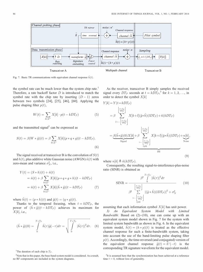
Bandwidth: Based on (2)–(10), one can come up with anequivalent system model shown in Fig. 7 for the system withlimited system bandwidth as shown in Fig. 6. In the equivalentsystem model, is treated as the effectivechannel response for such a finite-bandwidth system, takinginto account the use of the band-limiting pulse shaping filter
. Accordingly, the time-reversed (and conjugated) version ofthe equivalent channel response is thecorresponding TR signature waveform for the equivalent model.
Fig. 7. Basic TR communications with equivalent channel response .
1The duration of each chip is .2Note that in this paper, the base-band systemmodel is considered. As a result,
no RF components are included in the system diagrams.
3It is assumed here that the synchronization has been achieved at a referencetime , without loss of generality.
86 IEEE INTERNET OF THINGS JOURNAL, VOL. 1, NO. 1, FEBRUARY 2014
In the following discussion of the TRDMA scheme in thispaper, we use the simpler equivalent model by looking at theeffective channel response , which can beverified by comparing Figs. 6 and 7.
III. ASYMMETRIC TRDMA ARCHITECTURE FOR IOT
Based on TR technique, we recently introduced in [25] a novelmulti-user media access scheme, TRDMA, for wideband com-munication. Leveraging the unique temporal and spatial focusingeffects of the TR technique [24], [61], the TRDMA exploits thespatial degrees of freedom of the environment and uses themulti-path channel profile associated with each user’s location as alocation-specific signature for the user. Moreover, such channelprofiles may be further improved by mixing spatial degreesof freedom and temporal degrees of freedom as shown in [62]and [63].
With the concept of TRDMA, in this section, we propose anasymmetric TRDMA architecture for IoT, where most of thecomputational complexities are concentrated at the more pow-erful base station (BS), resulting in a minimal complexity andcost at the terminal devices in both uplink and downlink. Asshown in Fig. 1, the proposed IoT system consists of multiple TRBSs and each BS serves multiple heterogeneous terminal de-vices, which ranges from laptop and TV to light and clothes. Inthe following, we will first focus on the single BS scenario andthen discuss the multiple-BS scenario in Section III-E.
A. Channel Probing Phase
Consider awireless broadbandmulti-user network that consistsof one BS and terminal users.4 Each user communicates withBS simultaneously over the same spectrum. Assuming a rich-scattering environment, each user’s location is associated with aunique (effective) channel response , .
The channel probing occurs when a terminal user joins thenetwork, and periodically afterwards.5 The channel probingprocess is performed for one user at a time. For the th user’schannel probing, the terminal user first sends a pulse pilot signal
to the BS, so that the TRmirror at the BS can record and timereverse (and conjugate, if complex-valued) the received wave-form , and use the TR waveform as the basic signaturewaveform, given by6
B. Data Transmission Phase—Downlink
After the channel recording phase, the system starts its datatransmission phase. We first introduce the downlink scheme inthis part. In the downlink scheme, at the BS, each of
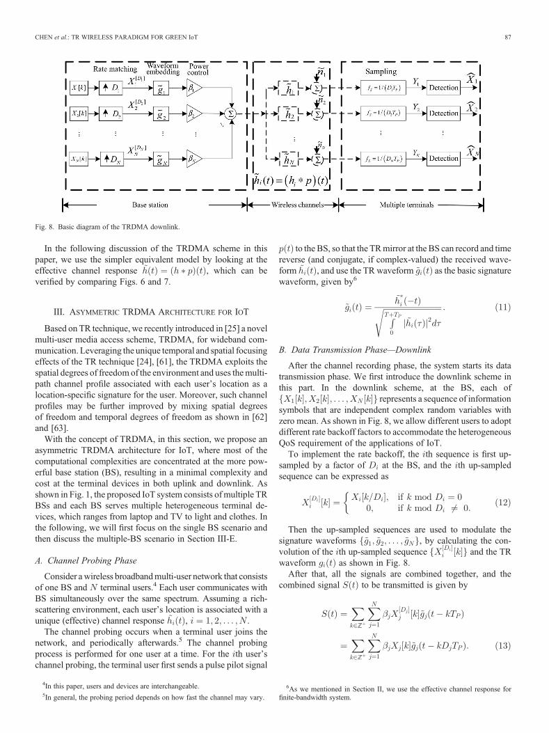
represents a sequence of informationsymbols that are independent complex random variables withzero mean. As shown in Fig. 8, we allow different users to adoptdifferent rate backoff factors to accommodate the heterogeneousQoS requirement of the applications of IoT.
To implement the rate backoff, the th sequence is first up-sampled by a factor of at the BS, and the th up-sampledsequence can be expressed as
Then the up-sampled sequences are used to modulate thesignature waveforms , by calculating the con-volution of the th up-sampled sequence and the TRwaveform as shown in Fig. 8.
After that, all the signals are combined together, and thecombined signal to be transmitted is given by
Z
Z
Fig. 8. Basic diagram of the TRDMA downlink.
4In this paper, users and devices are interchangeable.5In general, the probing period depends on how fast the channel may vary.
6As we mentioned in Section II, we use the effective channel response forfinite-bandwidth system.
CHEN et al.: TR WIRELESS PARADIGM FOR GREEN IoT 87
In essence, by convolving the information symbol sequenceswith TR waveforms, the TR structure provides a mechanism ofembedding the unique location-specific signature associatedwith each communication link into the transmitted signal forthe intended user.
The signal received at user is represented as follows:
Z
which is the convolution of the transmitted signal and thechannel response , plus an AWGN sequence with zeromean and variance .
Thanks to the temporal focusing effect, the th receiver (user )simply samples the received signal every seconds at
, ending up with given as follows:
where , and
⩽ ⩽
⩽ <
Thanks to the spatial focusing effect, in (16), when , thepower of is typically very small compared tothe power of the , which suppresses the inter-user-interference (IUI) for the TRDMA downlink.
Consequently, based on (15), the resulting SINR for user inthe TRDMA downlink is given by
where
and
C. Data Transmission Phase—Uplink
In this part, we describe the TRDMA uplink scheme, whichfacilitated, together with the downlink scheme, the asymmetricTRDMA architecture for IoT. Given the asymmetric complexitydistribution between BS and terminal users in the downlink, thedesign philosophy of such a uplink is to keep the complexity ofterminal users at minimal level.
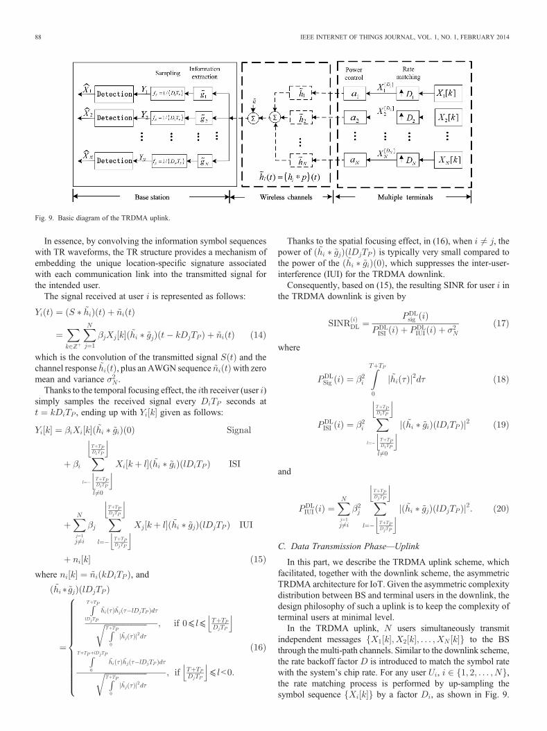
In the TRDMA uplink, users simultaneously transmitindependent messages to the BSthrough the multi-path channels. Similar to the downlink scheme,the rate backoff factor is introduced to match the symbol ratewith the system’s chip rate. For any user , ,the rate matching process is performed by up-sampling thesymbol sequence by a factor , as shown in Fig. 9.
Fig. 9. Basic diagram of the TRDMA uplink.
88 IEEE INTERNET OF THINGS JOURNAL, VOL. 1, NO. 1, FEBRUARY 2014

The up-sampled sequence of modulated symbols for user can beexpressed as
The scaling factors , for in Fig. 9, are usedto implement the transmit power control, whose values areassumed to be instructed by the BS through the feedback/controlchannel. After multiplying with scaling factor, the sequence of
for all is transmitted through thecorresponding multi-path channel .
When the sequence propagates through its wire-less channel , the convolution between and theeffective channel response is automatically taken asthe channel output for user . Then, all of the channel outputsfor the users are mixed together in the air plus the AWGNat the BSwith zero mean and variance , as illustrated in Fig. 9.Consequently, the mixed signal received at the BS can be writtenas
Z
Upon receiving the mixed signal as shown in (22), the BSpasses this mixed signal through a bank of filters, each ofwhich performs the convolution between its input signal andthe user’s signature waveform that has been calculated forthe downlink. Such a convolution using the signature waveformextracts the useful signal component and suppresses the signalsof other users. As the output of the th filter, i.e., the convolutionof and the signature of user , can be represented as
Z
in which the highest gain for user ’s symbol is achieved atthe temporal focusing time .
Sampling every seconds at , we have
where is a sample of the colored noiseafter the filtering, which is still a Gaussian random variablewith zero mean and the same variance , since is a normal-ized waveform as shown in (11).
Examining (15) and (24), the samemathematical structure canbe found by switching the roles of the signature waveforms ’sand the channel responses ’s in the convolution (and ignoringthe scaling factor and noise term.) Therefore,mathematically,7
a virtual spatial focusing effect as observed in the downlink canbe seen in the user’s signature domain of the proposed uplinkscheme. Such a virtual spatial focusing effect enables the BS touse the user’s signature waveform to extract the useful compo-nent out of the combined received signals, allowing multipleusers to access the BS simultaneously.
Fig. 10. Performance comparison between TRDMA and UWB in terms ofaverage achievable data rate per user.
Fig. 11. Performance comparison between TRDMA and UWB in terms ofnumber of supported users.
7Unlike the physical spatial focusing effect observed in the downlink in whichthe useful signal power is concentrated at different physical locations, in theuplink, the signal power concentration in the users’ signature waveform space isachieved mathematically at the BS.
CHEN et al.: TR WIRELESS PARADIGM FOR GREEN IoT 89
Consequently, based on (24), the resulting SINR for user inthe TRDMA uplink is given by
where
and
D. Performance of TRDMA
In this section, we compare the performance of the proposedTRDMA system with that of the UWB impulse radio system interms of different metrics, where we assume that the UWBimpulse radio system uses the ideal Rake receiver that collectsall the taps of channel information. We first compare the averageachievable data rate of each user when the power consumption isthe same for two systems. As shown in Fig. 10, the TRDMAsystem is able to provide higher achievable data rate for each userthan the UWB impulse radio system.
We then evaluate the number of users where each system cansupport. Since TRDMAmitigates the interference among users, itis expected to be able to support more users. In Fig. 11, we showthe number of supported users versus the average achievable rateof each user.We can see that, aswe have anticipated, the TRDMAsystem is able to support more users than the UWB impulse radiosystem. For example, if the required data rate of each user is0.1 bps/Hz, which is equivalent to 10 Mbps if the bandwidth is100 MHz, then the TRDMA system can support about 20 userswhile the UWB impulse radio system can support only five users.
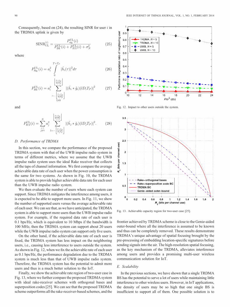
On the other hand, if the achievable data rate of each user isfixed, the TRDMA system has less impact on the neighboringusers, i.e., causing less interference to users outside the system.As shown in Fig. 12, when we fix the achievable rate of each useras 0.1 bps/Hz, the performance degradation due to the TRDMAsystem is much less than that of UWB impulse radio system.Therefore, the TRDMA system has the potential to admit moreusers and thus is a much better solution to the IoT.
Finally, we show the achievable rate region of two-user case inFig. 13, wherewe further compare the proposedTRDMAsystemwith ideal rake-receiver schemes with orthogonal bases andsuperposition codes [25]. We can see that the proposed TRDMAscheme outperforms all the rake-receiver-based schemes, and the
frontier achieved by TRDMA scheme is close to the Genie-aidedouter-bound where all the interference is assumed to be knownand thus can be completely removed. These results demonstrateTRDMA’s unique advantage of spatial focusing brought by thepre-processing of embedding location-specific signatures beforesending signals into the air. The high-resolution spatial focusing,as the key mechanism of the TRDMA, alleviates interferenceamong users and provides a promising multi-user wirelesscommunication solution for IoT.
E. Scalability
In the previous sections, we have shown that a single TRDMABS has the potential to serve a lot of users while maintaining littleinterference to other wireless users. However, in IoT applications,the density of users may be so high that one single BS isinsufficient to support all of them. One possible solution is to
Fig. 12. Impact to other users outside the system.
Fig. 13. Achievable capacity region for two-user case [25].
90 IEEE INTERNET OF THINGS JOURNAL, VOL. 1, NO. 1, FEBRUARY 2014
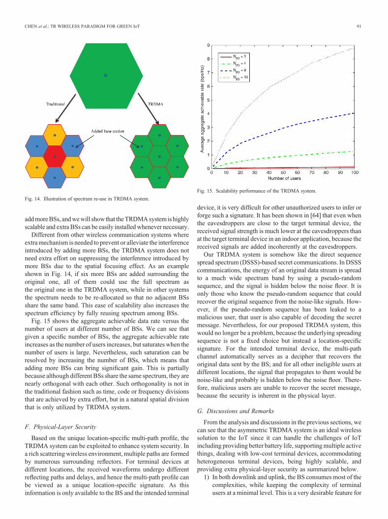
addmoreBSs, andwewill show that theTRDMAsystem is highlyscalable and extra BSs can be easily installedwhenever necessary.
Different from other wireless communication systems whereextramechanism is needed to prevent or alleviate the interferenceintroduced by adding more BSs, the TRDMA system does notneed extra effort on suppressing the interference introduced bymore BSs due to the spatial focusing effect. As an exampleshown in Fig. 14, if six more BSs are added surrounding theoriginal one, all of them could use the full spectrum asthe original one in the TRDMA system, while in other systemsthe spectrum needs to be re-allocated so that no adjacent BSsshare the same band. This ease of scalability also increases thespectrum efficiency by fully reusing spectrum among BSs.
Fig. 15 shows the aggregate achievable data rate versus thenumber of users at different number of BSs. We can see thatgiven a specific number of BSs, the aggregate achievable rateincreases as the number of users increases, but saturates when thenumber of users is large. Nevertheless, such saturation can beresolved by increasing the number of BSs, which means thatadding more BSs can bring significant gain. This is partiallybecause although different BSs share the same spectrum, they arenearly orthogonal with each other. Such orthogonality is not inthe traditional fashion such as time, code or frequency divisionsthat are achieved by extra effort, but in a natural spatial divisionthat is only utilized by TRDMA system.
F. Physical-Layer Security
Based on the unique location-specific multi-path profile, theTRDMA system can be exploited to enhance system security. Ina rich scattering wireless environment, multiple paths are formedby numerous surrounding reflectors. For terminal devices atdifferent locations, the received waveforms undergo differentreflecting paths and delays, and hence the multi-path profile canbe viewed as a unique location-specific signature. As thisinformation is only available to the BS and the intended terminal
device, it is very difficult for other unauthorized users to infer orforge such a signature. It has been shown in [64] that even whenthe eavesdroppers are close to the target terminal device, thereceived signal strength is much lower at the eavesdroppers thanat the target terminal device in an indoor application, because thereceived signals are added incoherently at the eavesdroppers.
Our TRDMA system is somehow like the direct sequencespread spectrum (DSSS)-based secret communications. In DSSScommunications, the energy of an original data stream is spreadto a much wide spectrum band by using a pseudo-randomsequence, and the signal is hidden below the noise floor. It isonly those who know the pseudo-random sequence that couldrecover the original sequence from the noise-like signals. How-ever, if the pseudo-random sequence has been leaked to amalicious user, that user is also capable of decoding the secretmessage. Nevertheless, for our proposed TRDMA system, thiswould no longer be a problem, because the underlying spreadingsequence is not a fixed choice but instead a location-specificsignature. For the intended terminal device, the multi-pathchannel automatically serves as a decipher that recovers theoriginal data sent by the BS; and for all other ineligible users atdifferent locations, the signal that propagates to them would benoise-like and probably is hidden below the noise floor. There-fore, malicious users are unable to recover the secret message,because the security is inherent in the physical layer.
G. Discussions and Remarks
From the analysis and discussions in the previous sections, wecan see that the asymmetric TRDMA system is an ideal wirelesssolution to the IoT since it can handle the challenges of IoTincluding providing better battery life, supportingmultiple activethings, dealing with low-cost terminal devices, accommodatingheterogeneous terminal devices, being highly scalable, andproviding extra physical-layer security as summarized below.
1) In both downlink and uplink, the BS consumes most of thecomplexities, while keeping the complexity of terminalusers at a minimal level. This is a very desirable feature for
Fig. 14. Illustration of spectrum re-use in TRDMA system.
Fig. 15. Scalability performance of the TRDMA system.
CHEN et al.: TR WIRELESS PARADIGM FOR GREEN IoT 91
the solution to IoT since it can provide much better batterylife and reduce the cost of the terminal devices and thus theentire system as a whole.
2) Both downlink and uplink can support simultaneous trans-missions of multiple users since the TRDMA system inessence forms a virtual massive MISO technology thatleverages the large number of multi-paths in the rich-scattering environment. The downlink has a physicalspatial focusing effect; whereas the uplink has a virtualspatial focusing effect due to the mathematical dualitybetween the TRDMA uplink and downlink.
3) Different users can adopt different rate backoff factors toachieve heterogeneous QoS requirements, i.e., theTRDMA system can accommodate heterogeneous termi-nal devices for IoT.
4) More BSs can be easily added in the TRDMA systemwithout extra mechanism for preventing or alleviating theinterference introduced, i.e., the TRDMA system is highlyscalable.
5) Based on the unique location-specific multi-path profile,the TRDMA system can provide extra system security inthe physical layer.
IV. OTHER CHALLENGING ISSUES AND FUTURE DIRECTIONS
A. Advanced Waveform Design
In our discussion of TRDMA in the previous section, the TRCIR serves as the transmit signature waveform to modulatesymbols. The received signal is the transmitted waveformconvolving with the multi-path channel with additive noise. Sucha time-reversed waveform is essentially the matched filter [65],which guarantees the optimal BER performance by virtue of itsmaximum signal-to-noise ratio (SNR). However, in high data ratescenario such as video streaming, when the symbol duration issmaller than the channel delay spread, the transmit waveforms areoverlapped and thus interfere with each other. When the symbolrate is very high, such ISI can be notably severe and causes crucialperformance degradation, i.e., the BER performance can be verypoor with a basic time-reversed waveform. Further, in multi-userdownlink scenario, the TR BS uses each user’s particular CIR asits specific waveform to modulate the symbols intended for thatuser. Despite the inherent randomness of the CIRs, as long as theyare not orthogonal to each other, which is almost always the case,these waveforms will inevitably interfere with each other whentransmitted concurrently.Hence, the performance ofTRDMAcanbe impaired and even limited by the IUI.
Based on given design criteria such as system performance,QoS constraints, or fairness among users, the waveform designcan be formulated as an optimization problem with the transmit-ted waveforms as the optimization valuables. The basic idea ofwaveform design is to carefully adjust the amplitude and phase ofeach tap of the waveform based on the channel information, suchthat after convolving with the channel, the received signal at thereceiver retains most of the intended signal strengths and rejectsor suppresses the interference as much as possible.
To rewrite (15) in a vector from, we define the followingnotations. The multipath channel between the base-station and
the th user is denoted by a vector , a column vector of
elements where and . Let
denote an information symbol for user , and be the transmit
waveform for user , where in (15). Thelength of is also . The received signal vector at user ,where in (15), is given by
where is the Toeplitz matrix of size with thefirst column being , and denotes the AWGNwith . User estimates the symbol by the sample
. Note that (29) represents the received signal when the ratebackoff factor > . When < , the received waveforms ofdifferent symbols overlap with each other and give rise to the ISI.To characterize the effect of ISI, the decimated channel matrix ofsize , where , is defined as
where is the th column of a identitymatrix. In other words, is obtained by decimating the rows of
by , i.e., centering at the th row, every th row of iskept in while the other rows are discarded. The center rowindex of is . Then the sample for symbol estimation can bewritten as
where denotes the th row of , and denotesuser ’s th symbol. It can be seen from (31) that the symbol
, the th symbol of user , is interfered by the previoussymbols and the later symbols as well as other
users’ symbols, and also corrupted by the noise.The design of waveforms has critical influence to thesymbol estimation and thus the system performance.
It can be observed that themathematical structure ofwaveformdesign is similar to the beamforming problem, which is alsoknown as the multi-antenna precoder design [66]–[70]. There-fore, beamforming approaches, such as singular value decom-position (SVD), zero forcing (ZF), and minimal mean squareerror (MMSE), can be analogously employed in waveformdesign. In the literature, there have been many studies investi-gating the problems of designing advanced waveforms to sup-press the interference [27], [46], [71]–[76]. If the basic TRwaveforms are adopted, i.e., , then the intended signalpower for each user is maximized but without considering theinterference caused by other symbols. As such, the performanceis limited by the interference when the transmit power is high.Another possible waveform design is ZF [77], which minimizesall the interference signal power but without taking into account
92 IEEE INTERNET OF THINGS JOURNAL, VOL. 1, NO. 1, FEBRUARY 2014

the intended signal power. Thus, the resulting SNR can be verylow and causes severe performance degradation especially whenthe transmit power is relatively low. In [27], it has been shownthat well-designed waveforms can strike a balance betweenenhancing the intended signal power and suppressing the inter-ference power.
Besides the channel information, another important side in-formation the transmitter can exploit in waveform design, is thetransmitted symbol information. The waveform of one symbol,when arriving at the receiver, induces ISI to the previous symbolsas well as the following symbols. Given what has been trans-mitted, the causal part of ISI can be canceled in advance indesigning the waveform of the current symbol. Such a designpholosophy is analogous to the transmitter-based interferencepre-subtraction [78]–[80] in the nonlinear precoding literature. Anotable distinction for TR systems is that only the causal part ofISI can be canceled while the anti-causal part of ISI cannot becanceled and needs to be suppressed by the waveform designbased on channel information [49].
Fig. 16 shows theBERperformance for a single user TR systemwhen using different waveforms, including basic TRwaveform, the waveform design in [27], and the joint waveformdesign and interference pre-cancelation in [49]. It can be seen thatwhen , the ISI is so severe that the BER curve of the basicTR waveform starts to saturate at even middle SNR, which isunacceptable. The waveform design in [27] is able to suppress theinterference and make the BER keep decreasing when SNRincreases. The joint waveform design and interference pre-cancelation in [49] can further improve the performance signifi-cantly since it makes use ofmore information, i.e., the transmittedsymbols, to cancel the ISI in advance. It is evident that thedramatic performance improvement brought from the waveformdesign demonstrates its inevitable necessity in TR systems.
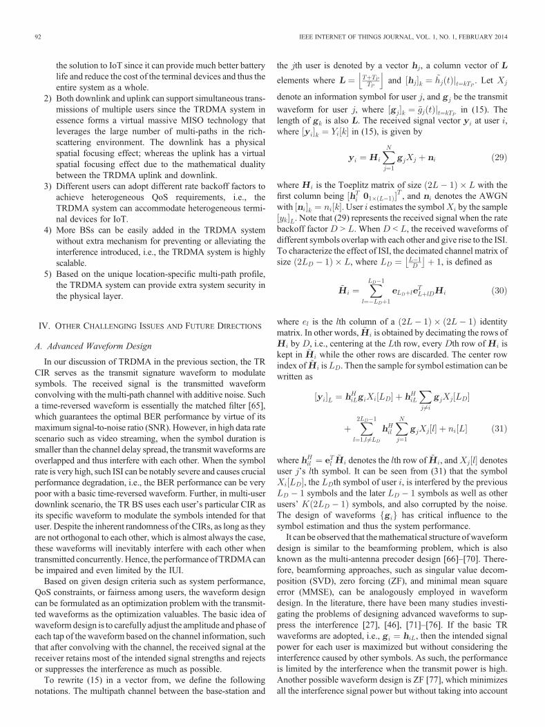
Fig. 17 shows the performance comparison in terms ofachievable rate of the TRDMA systemwith 500-MHz bandwidthwith two OFDM systems: one is LTE system with 20-MHzbandwidth and the other is LTE-A system with 100-MHzbandwidth. We can see that for one user case, even with basic
TR waveform, the TRDMA scheme can achieve much betterperformance than LTE in all SNR region and better performancethan LTE-A in most SNR region. With optimal waveform, theperformance of TRDMA can be further improved. When thereare 10 users, due to the selectivity among different users, theachievable rate of LTE and LTE-A can be enhanced, due towhich LTE-A can achieve comparable and even slightly betterperformance than TRDMA with basic TR waveform. Neverthe-less, with optimal waveform, TRDMA can still outperform LTEand LTE-A in most SNR region, which demonstrates thatTRDMA can achieve higher throughput than OFDM systemswhen the bandwidth is wide enough, e.g., five times as in thesimulations.
B. Medium Access Control (MAC) Layer Issue
TheMAC layer provides addressing and channel access controlmechanisms thatmake it possible for several terminals or networknodes to communicate within a multiple access network thatincorporates a shared medium [81]. In the MAC layer design,coordination is the most basic and important function, whichmanagesmultiple users to access the networkwith the objective ofboth efficiency and fairness. Most of the existing prevailingsystems, such as IEEE 802.11 WiFi and IEEE 802.15.4 ZigBee,are based on the contention scheme. For example, in WiFisystems, distributed coordination function (DCF) is adopted withCarrier Sensing Multiple Access (CSMA) and Collision Avoid-ance (CA) [82]. When a WiFi user has packet to transmit, it firstsenses the channel, i.e., “Listen-Before-Talk.”After detecting thechannel as idle, the WiFi user has to keep sensing the channel foran additional random time [83], i.e., random backoff and onlywhen the channel remains idle for this additional random timeperiod, the station is allowed to initiate its transmission. If there is acollision, the user needs to backoff and repeat this procedureagain. Under such a scheduling, there is only one WiFi usertalking with the AP at one time. However, when the number ofusers is large, no one can access the network due to the contentionfailure and extremely long backoff. We have all seen and experi-enced such a phenomenon in highly dense-population area in-cluding airport and conference hall. A typical example is thatSteve Jobs failed to demo the WiFi function of the new releasediPhone due to the overwhelming connections in the conferenceroom [84]. Therefore, such a contention-based coordinationfunction of the MAC layer is a bottleneck for accommodatinglarge number of users, which generally exists in IoT.
The most prominent characteristic of the TR system is that itdoes not require such coordination function, where users arenaturally separated by their locations. There are two phases in theTR systems: channel probing phase and data transmission phase.In the channel probing phase, all the users can transmit theirunique pilots (e.g., pseudo-noise sequences) to the BS forchannel estimation. In the data transmission phase, BS cancommunicate with all the users simultaneously through loca-tion-specific signatures. Therefore, there is no need for the BS inTR systems to perform coordination function, which simplify theMAC layer design to a large extent. In addition to coordination,some additional functionalities required by the MAC are alsoneeded in TR systems, including accepting MAC Service Data
Fig. 16. BER performance comparison using basic TR waveform, waveformdesign, and joint waveform design and interference pre-cancelation.
CHEN et al.: TR WIRELESS PARADIGM FOR GREEN IoT 93
Units (MSDUs) from higher layers and adding headers andtrailers to create MAC protocol data unit (MPDU) for physicallayer, fragmenting one frame into several frames to increase thedelivery probability, and encryptingMAC layer packet to ensuresecurity and privacy [83]. Nevertheless, we would like toemphasize again that the location-specific signature in TRsystems can provide additional physical-layer security.
C. Low-Cost High-Speed ADC and DAC
The inherent nature of TR communications is to fully harvestenergy from the surrounding environment by exploiting themulti-path propagation to re-collect all the signal energy thatcould be collected. To have superior advantage, the TR com-munications need to operate in a rich multi-path environment,which generally require wide bandwidth. As a consequence, thesampling rate is typically high. Moreover, to avoid missing thepeak during the sampling and simplify the synchronizationprocess, a two to four times oversampling is generally required,whichmake the sampling evenmore challenging. Therefore, onekey implementation issue in TR communications is the highsampling rate of the ADC. Fortunately, due to the advance ofsemiconductor technologies and the continuous driven from theemerging wideband communication applications, the perfor-mance of ADC has been improved a lot during the past decadein terms of both sampling rate and resolution. For example, thereare 17 different commercial off-the-shelf ADCs from TexasInstrument with sampling rate at least 1 GHz and resolution atleast 8 bits [85]. However, the price of such ADCs is typicallyhigh, e.g., an ADC with two-channel 2-GHz sampling rate and8 bits resolution costsUS$329,whichmay barrier the applicationof TR technique on IoT. In such a case, there is a need to findcheaper solutions to high sampling rate ADCs.
There are twopossibleways to reduce the cost of high samplingrateADCs.Thefirstway is to implement theADConchip. In sucha case, the cost of ADC comes from the silicon cost, whichdepends on silicon wafer cost and the size of the ADC on silicon.In general, with silicon implementation, the cost of ADC can bereduced from several hundred dollars to several cents without
considering the capital cost. Nevertheless, since the capital cost istypically very high, such kind of implementation is only suitablefor large volume productions. The other way to reduce the cost isusing a set of low sampling rate cheap ADCs to achieve the highsampling rate. As the price of commercial ADCs grows exponen-tially with the increase in sampling rate, by replacing the highsampling rate ADCs with a set of low sampling rate ADCs, thecost can be reduced dramatically. One straightforward way is touse time interleaving [86], [87]. In such an approach, the inputsignal is passed through a series of parallel interleaved lowsampling rate ADCs where the interleaving is achieved throughthe time shifts. After the sampling, the samples are passed throughthe de-interleaver to generate the high sampling rate signal.However, the front end of a commercial ADC has an inherentanalog bandwidth limitation [88], [89], due to which the timeinterleaving approach is not practical. The second approach is touse parallel bandpass sampling approach [90], [91] where theinput signal is passed through a series of filter bank before theADCs and the reconstruction method depends on the correspond-ing filters in the filter bank. This kind of approach can resolve theanalog bandwidth limitation but necessitates sophisticated digitalalgorithms for accurate frequency synchronization. Another ap-proach is to use random demodulation [92], [93] where the inputsignal is passed through parallel channels. In each channel, theinput signal is first multiplied by a periodic random waveform inthe analog domain, then lowpass filtered, and finally sampledusing low sampling rate ADC. The random demodulation ap-proaches overcomes the disadvantages of the time interleavingapproach and the parallel bandpass sampling approach, but islimited by the technology for generating the periodic randomwaveforms. Note that in all these approaches, the costly highsampling rate ADC is traded with the computation complexity forreconstruction in digital domain which is relatively cheap.
V. CONCLUSION
In this paper, we provide an overview to show that the TRtechnique is an ideal paradigm for IoT. Because of the inherentnature to fully harvest energy from the surrounding environment
Fig. 17. Achievable rate comparison: (a) 1 user case and (b) 10 users case.
94 IEEE INTERNET OF THINGS JOURNAL, VOL. 1, NO. 1, FEBRUARY 2014

by exploiting the multi-path propagation to recollect all the signalenergy, the TR system has a potential of over an order ofmagnitude of reduction in power consumption and interferencealleviation, which means that TR system can provide betterbattery life and support multiple concurrent active users. Theunique asymmetric architecture proposed in this paper can sig-nificantly reduce the computational complexity and thus the costof the terminal devices, the total number ofwhich is typically verylarge for IoT.Moreover, through adjusting the waveform and ratebackoff factor, various QoS options can be easily supported in TRsystems. Finally, the unique location-specific signature in TRsystemcan provide additional physical-layer security and thus canenhance the privacy and security of customers in IoT. All theseadvantages, including providing better battery life, supportingmultiple active things, dealing with low-cost terminal devices,accommodating heterogeneous terminal devices, being highlyscalable and providing extra physical-layer security, show thatthe TR technique is an ideal paradigm for IoT.
Recently, researchers start to envision the next major phase ofmobile telecommunications standards beyond current 4G stan-dards, known as 5G. According to [94], key concepts of 5Ginclude new modulation techniques such as non-orthogonalmultiple access schemes, massive distributed MIMO, advancedinterference management, and efficient support of machine-typedevices to enable the IoT with potentially higher numbers ofconnected devices. Based on the discussion in this paper, it turnsout that TR can easily resolve these issues, which means that TRis potentially a promising 5G technology.
REFERENCES
[1] G.Kortuem, F.Kawsar, D. Fitton, andV. Sundramoorthy, “Smart objects asbuilding blocks for the internet of things,” IEEE Internet Comput., vol. 14,no. 1, pp. 44–51, Feb. 2010.
[2] C. Institutes, “Smart networked objects and internet of things,” in Proc. Inf.Commun. Technol.MicroNano Technol. Alliance, White Paper, Jan. 2011.
[3] L. Atzori, A. Iera, and G. Morabito, “The internet of things: A survey,”Comput. Netw., vol. 54, no. 15, pp. 2787–2805, Oct. 2010.
[4] D.Le-Phuoc,A. Polleres,M.Hauswirth,G. Tummarello, andC.Morbidoni,“Rapid prototyping of semantic mash-ups through semantic web pipes,”in Proc. 18th Int. Conf. World Wide Web, 2009, pp. 581–590.
[5] A. Dohr, R. Modre-Opsrian, M. Drobics, D. Hayn, and G. Schreier, “Theinternet of things for ambient assisted living,” in Proc. Int. Conf. Inf.Technol.: New Gener. (ITNG), 2010, pp. 804–809.
[6] European Commission, “Internet of things in 2020 roadmap for the future,”Working Group. RFID of the ETP EPOSS, Tech. Rep., May 2008.
[7] K. Ashton, “That ‘internet of things’ thing in the real world, things mattermore than ideas,” RFID J., Jun. 2009.
[8] D. L. Brock, “The electronic product code (epc) a naming scheme forphysical objects,” Auto-ID Center, White Paper, Jan. 2001.
[9] I. T. Union, “ITU internet reports 2005: The internet of things,” in Proc.Workshop Rep. Int. Telecommun. Union, Nov. 2005.
[10] P. Guillemin and P. Friess, “Internet of things strategic research roadmap,”The Cluster of European Research Projects, Tech. Rep., Sep. 2009.
[11] C. Gomez and J. Paradells, “Wireless home automation networks: A surveyof architectures and technologies,” IEEE Commun. Mag., vol. 48, no. 6,pp. 92–101, Jun. 2010.
[12] J. Berman, “Z-wave chip aims to cut implementation cost,” EDN Netw.,pp. 92–101, Apr. 2005.
[13] IEEE Standard for Telecommunications and Information Exchange BetweenSystems—lan/man—Specific Requirements—Part 15: Wireless MediumAccess Control (mac) and Physical Layer (phy) Specifications for WirelessPersonal Area Networks (wpans), IEEE 802.15.1-2002 [Online]. Available:http://ieeexplore.ieee.org/xpl/mostRecentIssue.jsp?punumber=7932
[14] Wireless lan Medium Access Control (mac) and Physical Layer (phy)Specification, IEEE 802.11 [Online]. Available: http://standards.ieee.org/getieee802/download/802.11-2012.pdf
[15] L. Li, X. Hu, K. Chen, and K. He, “The applications of wifi-based wirelesssensor network in internet of things and smart grid,” in Proc. IEEE Conf.Ind. Electron. Appl. (ICIEA), 2011, pp. 789–793.
[16] M.Ha, S.H.Kim,H.Kim,K.Kwon,N.Giang, andD.Kim, “Snail gateway:Dual-mode wireless access points for wifi and ip-based wireless sensornetworks in the internet of things,” in Proc. IEEE Consum. Commun. Netw.Conf. (CCNC), 2012, pp. 169–173.
[17] X. Xie, D. Deng, and X. Deng, “Design of embedded gateway softwareframework for heterogeneous networks interconnection,” inProc. Int. Conf.Electron. Optoelectron. (ICEOE), 2011.
[18] Digi-key corporation’s website [Online]. Available: http://www.digikey.com/product-detail/en/CC2531F256RHAT/296-25186-2-ND/2171344?WT.mc_id=PLA_2171344
[19] (2013). Insteon compared. White Paper [Online]. Available: https://www.insteon.com/pdf/insteoncompared.pdf
[20] C. Corporation. (2005). Wi-fi radio characteristics and the cost ofwlan implementation [Online]. Available: http://www.connect802.com/download/techpubs/2005/commercial_radios_E0523-15.pdf
[21] H.-C. Hsieh and C.-H. Lai, “Internet of things architecture based onintegrated plc and 3g communication networks,” in Proc. IEEE Int. Conf.Parallel Distrib. Syst., 2011, pp. 853–856.
[22] Z. Shi, K. Liao, S. Yin, and Q. Ou, “Design and implementation of themobile internet of things based on TD-SCDMA network,” in Proc. IEEEInt. Conf. Inf. Theory Inf. Secur., 2010, pp. 954–957.
[23] J.-M. Liang, J.-J. Chen, H.-H. Cheng, and Y.-C. Tseng, “An energy-efficient sleep scheduling with QoS consideration in 3gpp LTE-advancednetworks for internet of things,” IEEE J. Emerging Sel. Topics CircuitsSyst., vol. 3, no. 1, pp. 13–22, Mar. 2013.
[24] B. Wang, Y. Wu, F. Han, Y.-H. Yang, and K. J. R. Liu, “Green wirelesscommunications: A time-reversal paradigm,” IEEE J. Sel. Areas Commun.,Special on Energy-Efficient Wireless Communications, vol. 29, no. 8,pp. 1698–1710, Sep. 2011.
[25] F. Han, Y.-H. Yang, B. Wang, Y. Wu, and K. J. R. Liu, “Time-reversaldivision multiple access over multi-path channels,” IEEE Trans. Commun.,vol. 60, no. 7, pp. 1953–1965, Jul. 2012.
[26] Y. Chen, Y. Yang, F. Han, and K. J. R. Liu, “Time-reversal widebandcommunications,” IEEE Signal Process. Lett., vol. 20, no. 12,pp. 1219–1222, Dec. 2013.
[27] Y.-H. Yang, B.Wang,W. S. Lin, andK. J. R. Liu, “Near-optimal waveformdesign for sum rate optimization in time-reversal multiuser downlinksystems,” IEEE Trans. Wireless Commun., vol. 12, no. 1, pp. 346–357,Jan. 2013.
[28] B. Y. Zeldovich, N. F. Pilipetsky, and V. V. Shkunov, Principles of PhaseConjugation. Berlin, Germany: Springer-Verlag, 1985.
[29] A. P. Brysev, L. M. Krutyanskii, and V. L. Preobrazhenskii, “Wave phaseconjugation of ultrasonic beams,” Phys.-Uspekhi, vol. 41, no. 8,pp. 793–805, 1998.
[30] M. Fink, C. Prada, F. Wu, and D. Cassereau, “Self focusing in inhomoge-neous media with time reversal acoustic mirrors,” in Proc. IEEE Ultrason.Symp., 1989, vol. 2, pp. 681–686.
[31] C. Prada, F.Wu, andM. Fink, “The iterative time reversalmirror: A solutionto self-focusing in the pulse echo mode,” J. Acoust. Soc. Amer., vol. 90,no. 2, pp. 1119–1129, 1991.
[32] M. Fink, “Time reversal of ultrasonic fields. I. Basic principles,” IEEETrans. Ultrason. Ferroelectr. Freq. Control, vol. 39, no. 5,pp. 555–566, 1992.
[33] C. Dorme and M. Fink, “Focusing in transmit–receive mode throughinhomogeneous media: The time reversal matched filter approach,” J.Acoust. Soc. Amer., vol. 98, no. 2, pp. 1155–1162, 1995.
[34] A. Derode, P. Roux, andM. Fink, “Robust acoustic time reversal with high-order multiple scattering,” Phys. Rev. Lett., vol. 75, pp. 4206–4209,Dec. 1995.
[35] W. A. Kuperman, W. S. Hodgkiss, H. C. Song, T. Akal, C. Ferla, and D.R. Jackson, “Phase conjugation in the ocean: Experimental demonstrationof an acoustic time-reversal mirror,” J. Acoust. Soc. Amer., vol. 103, no. 1,pp. 25–40, 1998.
[36] H. C. Song, W. A. Kuperman, W. S. Hodgkiss, T. Akal, and C. Ferla,“Iterative time reversal in the ocean,” J. Acoust. Soc. Amer., vol. 105, no. 6,pp. 3176–3184, 1999.
[37] D. Rouseff, D. Jackson, W. L. J. Fox, C. Jones, J. Ritcey, and D. Dowling,“Underwater acoustic communication by passive-phase conjugation: The-ory and experimental results,” IEEE J. Ocean. Eng., vol. 26, no. 4,pp. 821–831, Oct. 2001.
[38] G. Edelmann, T. Akal, W. Hodgkiss, S. Kim, W. Kuperman, andH. C. Song, “An initial demonstration of underwater acoustic communica-tion using time reversal,” IEEE J. Ocean. Eng., vol. 27, no. 3, pp. 602–609,Jul. 2002.
CHEN et al.: TR WIRELESS PARADIGM FOR GREEN IoT 95
[39] B. E. Henty and D. D. Stancil, “Multipath-enabled super-resolution for RFand microwave communication using phase-conjugate arrays,” Phys. Rev.Lett., vol. 93, p. 243904, Dec. 2004.
[40] G. Lerosey, J. de Rosny, A. Tourin, A. Derode, G. Montaldo, and M. Fink,“Time reversal of electromagnetic waves,” Phys. Rev. Lett., vol. 92,p. 193904, May 2004.
[41] R. C. Qiu, C. Zhou, N. Guo, and J. Q. Zhang, “Time reversal withMISO forultrawideband communications: Experimental results,” IEEE AntennasWireless Propag. Lett., vol. 5, no. 1, pp. 269–273, Dec. 2006.
[42] G. Lerosey, J. de Rosny, A. Tourin, A. Derode, G. Montaldo, and M. Fink,“Time reversal of electromagnetic waves and telecommunications,” RadioSci., vol. 40, pp. 1–10, 2005.
[43] G. Lerosey, J. de Rosny, A. Tourin, A. Derode, and M. Fink, “Timereversal of wideband microwaves,” Appl. Phys. Lett., vol. 88, p. 154101,Apr. 2006.
[44] I. H. Naqvi, G. E. Zein, G. Lerosey, J. de Rosny, P. Besnier, A. Tourin, andM. Fink, “Experimental validation of time reversal ultrawide-band com-munication system for high data rates,” IETMicrowaves Antennas Propag.,vol. 4, pp. 643–650, 2010.
[45] J. de Rosny, G. Lerosey, and M. Fink, “Theory of electromagnetic time-reversal mirrors,” IEEE Trans. Antennas Propag., vol. 58, no. 10,pp. 3139–3149, Oct. 2010.
[46] M. Emami,M. Vu, J. Hansen, A. J. Paulraj, and G. Papanicolaou, “Matchedfilteringwith rate back-off for low complexity communications in very largedelay spread channels,” in Proc. Conf. Record 38th Asilomar Conf. SignalsSyst. Comput., 2004, vol. 1, pp. 218–222.
[47] H. T. Nguyen, I. Z. Kovacs, and P. C. F. Eggers, “A time reversaltransmission approach for multiuser UWB communications,” IEEE Trans.Antennas Propag., vol. 54, no. 11, pp. 3216–3224, Nov. 2006.
[48] N. Guo, B. M. Sadler, and R. C. Qiu, “Reduced-complexity uwb time-reversal techniques and experimental results,” IEEE Trans. Wireless Com-mun., vol. 6, no. 12, pp. 4221–4226, Dec. 2007.
[49] Y.-H. Yang and K. J. R. Liu, “Joint waveform design and interference pre-cancellation for time-reversal systems,” IEEE Trans. Commun., submitted.
[50] F. Han and K. J. R. Liu, “A multiuser TRDMA uplink system with 2Dparallel interference cancellation,” IEEE Trans. Commun., to be published.
[51] P. Kyritsi and G. Papanicolaou, “One-bit time reversal for wlan applica-tions,” inProc. IEEE Int. Symp.Pers. IndoorMobileRadioCommun., 2005,pp. 532–536.
[52] D.-T. Phan-Huy, S. B. Halima, and M. Helard, “Frequency division duplextime reversal,” in Proc. IEEE Globecom, 2011, pp. 1–5.
[53] G. Lerosey, J. de Rosny, A. Tourin, and M. Fink, “Focusing beyond thediffraction limit with far-field time reversal,” Science, vol. 315,pp. 1120–1122, Feb. 2007.
[54] F. Lemoult, G. Lerosey, J. deRosny, andM. Fink, “Resonantmetalenses forbreaking the diffraction barrier,” Phys. Rev. Lett., vol. 104, p. 203901,May 2010.
[55] R. C. Qiu, C. Zhou, N. Guo, and J. Q. Zhang, “Time reversal withMISO forultra-wideband communications: Experimental results,” IEEE AntennaWireless Propag. Lett., vol. 5, no. 1, pp. 269–273, Dec. 2006.
[56] K. F. Sander and G. A. L. Reed, in Transmission and Propagation ofElectromagnetic Waves, 2nd ed. New York, NY, USA: Cambridge Univ.Press, 1986.
[57] J. M. F. Moura and Y. Jin, “Time reversal imaging by adaptive interferencecanceling,” IEEE Trans. Signal Process., vol. 56, no. 1, pp. 233–247,Jan. 2008.
[58] J. M. F. Moura and Y. Jin, “Detection by time reversal: Single antenna,”IEEE Trans. Signal Process., vol. 55, no. 1, pp. 187–201, Jan. 2007.
[59] Y. Jin and J. M. F. Moura, “Time-reversal detection using antennaarrays,” IEEE Trans. Signal Process., vol. 57, no. 4, pp. 1396–1414,Apr. 2009.
[60] F. Han, Y.-H. Yang, B. Wang, Y. Wu, and K. J. R. Liu, “Time-reversaldivision multiple access in multi-path channels,” in Proc. Global Tele-commun. Conf., 2011, pp. 1–5.
[61] M. Lienard, P. Degauque, V. Degardin, and I. Vin, “Focusing gainmodel oftime-reversed signals in dense multipath channels,” IEEE Antennas Wire-less Propag. Lett., vol. 11, pp. 1064–1067, Aug. 2012.
[62] G. Montaldo, G. Lerosey, A. Derode, A. Tourin, J. de Rosny, and M. Fink,“Telecommunication in a disordered environment with iterative timereversal,” Waves Random Media, vol. 14, pp. 287–302, May 2004.
[63] F. Lemoult, G. Lerosey, J. de Rosny, and M. Fink, “Manipulating spatio-temporal degrees of freedom of waves in random media,” Phys. Rev. Lett.,vol. 103, p. 173902, Oct. 2009.
[64] X. Zhou, P. Eggers, P. Kyritsi, J. Andersen, G. Pedersen, and J. Nilsen,“Spatial focusing and interference reduction usingMISO time reversal in anindoor application,” in Proc. IEEE Workshop Statist. Signal Process.(SSP), 2007, pp. 307–311.
[65] J. Proakis and M. Salehi, in Digital Communications, 5th ed. New York,NY, USA: McGraw-Hill, 2008.
[66] F. Rashid-Farrokhi, K. J. R. Liu, and L. Tassiulas, “Transmit beamformingand power control for cellular wireless systems,” IEEE J. Sel. AreasCommun., vol. 16, no. 8, pp. 1437–1450, Oct. 1998.
[67] F. Rashid-Farrokhi, L. Tassiulas, and K. J. R. Liu, “Joint optimal powercontrol and beamforming in wireless networks using antenna arrays,” IEEETrans. Commun., vol. 46, no. 10, pp. 1313–1324, Oct. 1998.
[68] Y.-H. Yang, S.-C. Lin, and H.-J. Su, “Multiuser MIMO downlink beam-forming based on group maximum SINR filtering,” IEEE Trans. SignalProcess., vol. 59, no. 4, pp. 1746–1758, Apr. 2011.
[69] H. Sampath, P. Stoica, and A. Paulraj, “Generalized linear precoder anddecoder design for MIMO channels using the weighted MMSE criterion,”IEEE Trans. Commun., vol. 49, no. 12, pp. 2198–2206, Dec. 2001.
[70] F. Dietrich, R. Hunger,M. Joham, andW.Utschick, “Linear precoding overtime-varying channels in TDD systems,” in Proc. ICASSP’03, 2003, vol. 5,pp. 117–120.
[71] Z. Ahmadian, M. Shenouda, and L. Lampe, “Design of pre-rake DS-UWBdownlink with pre-equalization,” IEEE Trans. Commun., vol. 60, no. 2,pp. 400–410, Feb. 2012.
[72] Y. Jin, J. M. Moura, and N. O’Donoughue, “Adaptive time reversalbeamforming in dense multipath communication networks,” in Proc. 42ndAsilomar Conf. Signals Syst. Comput., Oct. 2008, pp. 2027–2031.
[73] R. C. Daniels and R. W. Heath, “Improving on time-reversal with MISOprecoding,” inProc. 8th Int. Symp.Wireless Pers. Commun.Conf., Aalborg,Denmark, 2005.
[74] L.-U. Choi and R. D. Murch, “A transmit preprocessing technique formultiuser MIMO systems using a decomposition approach,” IEEE Trans.Wireless Commun., vol. 3, no. 1, pp. 2–24, Jan. 2004.
[75] P. Kyritsi, G. Papanicolaou, P. Eggers, and A. Oprea, “Time reversaltechniques for wireless communications,” in Proc. IEEE Veh. Technol.Conf., 2004, vol. 4, pp. 47–51.
[76] M. Brandt-Pearce, “Transmitter-based multiuser interference rejection forthe downlink of a wireless CDMA system in a multipath environment,”IEEE J. Sel. Areas Commun., vol. 18, no. 3, pp. 407–417, Mar. 2000.
[77] P. Kyritsi, P. Stoica, G. Papanicolaou, P. Eggers, and A. Oprea, “Timereversal and zero-forcing equalization for fixed wireless access channels,”in Proc. 39th Asilomar Conf. Signals Syst. Comput., 2005, pp. 1297–1301.
[78] C. Windpassinger, R. F. H. Fischer, T. Vencel, and J. Huber, “Precoding inmultiantenna and multiuser communications,” IEEE Trans. Wireless Com-mun., vol. 3, no. 4, pp. 1305–1316, Jul. 2004.
[79] W. Yu, D. Varodayan, and J. Cioffi, “Trellis and convolutional precodingfor transmitter-based interference presubtraction,” IEEE Trans. Commun.,vol. 53, no. 7, pp. 1220–1230, Jul. 2005.
[80] M. H. M. Costa, “Writing on dirty paper,” IEEE Trans. Inf. Theory, vol. 29,no. 3, pp. 439–441, May 1983.
[81] Media access control [Online]. Available: http://en.wikipedia.org/wiki/Media_access_control
[82] G. Bianchi, “Performance analysis of the ieee 802.11 distributed coordina-tion function,” IEEE J. Sel. Areas Commun., vol. 18, no. 3, pp. 535–547,Mar. 2000.
[83] M. Ergen, Ieee 802.11 tutorial [Online]. Available: http://wow.eecs.berkeley.edu/ergen/docs/ieee.pdf
[84] Even Steve Jobs has demo hiccups [Online]. Available: http://news.cnet.com/8301-31021_3-20007009-260.html
[85] A/D Converters, Texas Instrument 2013. [Online]. Available: http://www.ti.com/lsds/ti/data-converters/analog-to-digital-converter-products.page/.
[86] A. Kohlenberg, “Exact interpolation of band-limited functions,” J. Appl.Phys., vol. 24, no. 12, pp. 1432–1436, 1953.
[87] Y.-P. Lin and P. Vaidyanathan, “Periodically nonuniform sampling ofbandpass signals,” IEEE Trans. Circuits Syst. II: Analog Digital SignalProcess., vol. 45, no. 3, pp. 340–351, Mar. 1998.
[88] M. El-Chammas and B. Murmann, “General analysis on the impact ofphase-skew in time-interleaved ADCs,” IEEE Trans. Circuits Syst. I:Regular Papers, vol. 56, no. 5, pp. 902–910, May 2009.
[89] P. Nikaeen andB.Murmann, “Digital compensation of dynamic acquisitionerrors at the front-end of high-performance a/d converters,” IEEE J. Sel.Topics Signal Process., vol. 3, no. 3, pp. 499–508, Jun. 2009.
[90] Y. Eldar and A. Oppenheim, “Filterbank reconstruction of bandlimitedsignals from nonuniform and generalized samples,” IEEE Trans. SignalProcess., vol. 48, no. 10, pp. 2864–2875, Oct. 2000.
[91] Y. Tian, D. Zeng, and T. Zeng, “Design and implementation of multifre-quency front end using bandpass over sampling,” in Proc. IET Int. RadarConf., 2009, pp. 1–4.
[92] J. Tropp, J. Laska, M. Duarte, J. Romberg, and R. Baraniuk, “Beyondnyquist: Efficient sampling of sparse bandlimited signals,” IEEE Trans. Inf.Theory, vol. 56, no. 1, pp. 520–544, Jan. 2010.
96 IEEE INTERNET OF THINGS JOURNAL, VOL. 1, NO. 1, FEBRUARY 2014

[93] M.Mishali andY. Eldar, “From theory to practice: Sub-nyquist sampling ofsparse wideband analog signals,” IEEE J. Sel. Topics Signal Process.,vol. 4, no. 2, pp. 375–391, Apr. 2010.
[94] “5g wiki,” [Online]. Available: http://en.wikipedia.org/wiki/5G.
Yan Chen (S’06–M’11) received the Bachelor’sdegree from the University of Science and Technolo-gy of China, Hefei, China, in 2004, theM.Phil. degreefrom Hong Kong University of Science and Technol-ogy (HKUST), Hong Kong, China, in 2007, and thePh.D. degree from the University of Maryland, Col-lege Park, MD, USA, in 2011.His current research interests include data science,
network science, game theory, social learning andnetworking, as well as signal processing and wirelesscommunications.
Dr. Chen is the recipient of multiple honors and awards including best paperaward from IEEE GLOBECOM, in 2013, Future Faculty Fellowship andDistinguished Dissertation Fellowship Honorable Mention from the Departmentof Electrical and Computer Engineering, in 2010 and 2011, respectively, Finalistof Deans Doctoral Research Award from A. James Clark School of Engineering,University of Maryland, in 2011, and Chinese Government Award for outstand-ing students abroad, in 2011.
Feng Han (S’08–M’14) received the B.S. and M.S.degrees from Tsinghua University, Beijing, China, in2007 and 2009, respectively, and the Ph.D. degreefrom the University of Maryland, College Park, MD,USA, in 2013, all in electrical engineering.Currently, he is a Senior Engineer with Corporate
Research and Development, Qualcomm Inc., SanDiego, CA, USA. His research interests include wire-less communications and networking, game theory,signal processing, and communication theory.He is a recipient of the First Prize in the 19th
ChineseMathematical Olympiad, the Best Thesis Award of TsinghuaUniversity,the honor of Excellent Graduate of Tsinghua University, the A. James ClarkSchool of Engineering Distinguished Graduate Fellowship, in 2009, and theFuture Faculty Fellowship, in 2012, both from the University of Maryland. Hiswork on time reversal techniquewas recognized by the university-level Inventionof the Year Award and The Jimmy H. C. Lin Invention Award, both at theUniversity of Maryland, in 2013, and his work on MIMO system received a BestPaper Award for at IEEE WCNC’08.
Yu-Han Yang (S’06) received the B.S. degree inelectrical engineering, in 2004, the M.S. degreein computer science and communication engineering,in 2007, from National Taiwan University, Taipei,Taiwan, and the Ph.D. degree in electrical and com-puter engineering from the University of Maryland,College Park, MD, USA, in 2013.His research interests include wireless communi-
cation and signal processing.Dr. Yang received Class A Scholarship from the
Department of Electrical and Computer Engineering(ECE), National Taiwan University, Taipei, Taiwan, in Fall 2005 and Spring2006. He is a recipient of Study Abroad Scholarship from Taiwan (R.O.C.)government, in 2009–2010. He received the University of Maryland InnovationAward in 2013.
Hang Ma received the B.S. degree in informationengineering from Northwestern Polytechnical Uni-versity, Xi’an, China, in 2010. Currently, he is pursu-ing the Ph.D. degree at the University of Maryland,College Park, MD, USA.His research interests include wireless communi-
cation and signal processing.Mr. Ma received the honor of Outstanding Gradu-
ate of Northwestern Polytechnical University, in2010.
YiHan received the B.S. degree in electrical engineer-ing from Zhejiang University, Hangzhou, China, in2011. Currently, he is pursuing the Ph.D. degree fromthe Department of Electrical and Computer Engineer-ing, University of Maryland, College Park, MD, USA.His current research interests mainly focus on time-
reversal communication technology.
Chunxiao Jiang (S’09–M’13) received the B.S.degree in information engineering from BeijingUniversity of Aeronautics and Astronautics (BeihangUniversity), Beijing, China, in 2008 and the Ph.D.degree from Tsinghua University (THU), Beijing,China, in 2013, both with the highest honors.Currently, he is a Post-Doctor in EE Department,
THU, along with Prof. Yong Ren. He was a ResearchAssociate in ECEDepartment ofUMDwithProf.K. J.Ray Liu. From 2011 to 2012, he visited the Signalsand Information Group (SIG), Department of Electri-
cal and Computer Engineering (ECE), University of Maryland (UMD), CollegePark, MD, USA, supported by China Scholarship Council (CSC) for 1 year. Hisresearch interests include the applications of game theory and queuing theory inwireless communication and networking and social networks.Dr. Jiang received theBest PaperAward from IEEEGLOBECOM, in 2013, the
Beijing Distinguished Graduated Student Award, Chinese National Fellowshipand Tsinghua Outstanding Distinguished Doctoral Dissertation, in 2013.
Hung-Quoc Lai (M’11) received the B.S. (cumlaude), M.S., and Ph.D. degrees from the UniversityofMaryland, College Park, MD, USA, in 2004, 2006,and 2011, respectively, all in electrical engineering.His research interests include ultrawideband com-
munications, cooperative communications, and net-working.Dr. Lai is a Gates Millennium Scholar. He is the
recipient of university-level Distinguished TeachingAssistant Award from the University ofMaryland andthe 2005 George Corcoran Award from the Depart-
ment of Electrical and Computer Engineering, University of Maryland.
David Claffey received the B.A. degree in physics from Cornell University,Ithaca, NY, USA, in 1985.
Zoltan Safar received the University Diploma inelectrical engineering from the Technical Universityof Budapest, Budapest, Hungary, in 1996, and theM.S. and Ph.D. degrees in electrical and computerengineering from theUniversity ofMaryland, CollegePark, MD, USA, in 2001 and 2003, respectively.After graduation, he was an Assistant Professor
with the Department of Innovation, IT University ofCopenhagen, Copenhagen, Denmark, until March2005. Then, he joined Nokia, Copenhagen, Denmark,where he worked as a Senior Engineer on 3GPP Long
TermEvolution (LTE) receiver algorithmdesign. FromSeptember 2007, hewas aSenior Engineer with Samsung Electro-Mechanics, Atlanta, GA, USA, develop-ing physical-layer signal processing algorithms for next-generation wirelesscommunication systems. In February 2010, he became a Senior SoftwareEngineer with Bloomberg L.P., NY, USA, and he designed and implementedsoftware systems for monitoring, configuration and maintenance of the com-pany’s private communication network. SinceOctober 2010, he has beenwith theDepartment of Electrical and Computer Engineering, University of Maryland,where he is the Director of the MS in Telecommunications program.His researchinterests include wireless communications and statistical signal processing, withparticular focus on multi-antenna wireless communication systems, OFDM, andreceiver algorithm design.
CHEN et al.: TR WIRELESS PARADIGM FOR GREEN IoT 97
Dr. Safar received the Outstanding Systems Engineering Graduate StudentAward from the Institute for Systems Research, University ofMaryland, in 2003,and the Invention of the Year Award (together with W. Su and K. J. R. Liu) fromthe University of Maryland, in 2004.
K. J. Ray Liu (F’03) was a Distinguished Scholar-Teacher with the University of Maryland, CollegePark, MD, USA, in 2007, where he is a Christine KimEminent Professor of Information Technology. Heleads the Maryland Signals and Information Groupconducting research encompassing broad areas ofsignal processing and communications with recentfocus on cooperative and cognitive communications,social learning and network science, information for-ensics and security, and green information and com-munications technology.
Dr. Liu is the recipient of numerous honors and awards including IEEE SignalProcessing Society Technical Achievement Award and Distinguished Lecturer.He also received various teaching and research recognitions from the Universityof Maryland including university-level Invention of the Year Award; and PooleandKent Senior Faculty TeachingAward, Outstanding Faculty Research Award,and Outstanding Faculty Service Award, all from A. James Clark School ofEngineering. An ISI Highly Cited Author, he is a Fellow of AAAS. He is a PastPresident of IEEE Signal Processing Society, where he has served as VicePresident—Publications and Board of Governor. He was the Editor-in-Chief ofIEEE SIGNAL PROCESSING MAGAZINE and the founding Editor-in-Chief ofEURASIP Journal on Advances in Signal Processing.
98 IEEE INTERNET OF THINGS JOURNAL, VOL. 1, NO. 1, FEBRUARY 2014