ieee antennas and wireless propagation letters, vol. … · 2016-05-27 · osaretin et al.: compact...
TRANSCRIPT
IEEE ANTENNAS AND WIRELESS PROPAGATION LETTERS, VOL. 13, 2014 1533
A Compact 118-GHz Radiometer Antenna for theMicro-Sized Microwave Atmospheric Satellite
Idahosa A. Osaretin, Member, IEEE, Michael W. Shields, Senior Member, IEEE, Jose A. Martinez Lorenzo, andWilliam J. Blackwell, Senior Member, IEEE
Abstract—A linear polarized 118-GHz antenna is designed for aradiometer payload hosted aboard a 3U atmospheric CubeSat. Theradiometer antenna is a horn-fed offset parabolic reflector. Theantenna has a maximum dBi realized gain, 2.4 half-powerbeamwidth, and aminimum95%beam efficiencywithin the opera-tional bandwidth. The antenna is compact, meeting theMicroMASmission requirement for a highly integrated and ultra-compact ra-diometer. CubeSats present stringent size/volume and weight con-straints on overall component design.We present our design, alongwith simulated and measured results, that meet the size/volume,weight, and electrical requirements for the radiometer antennaand comply with CubeSat standards.
Index Terms—CubeSat, horn antennas, low Earth orbit satellite,microwave radiometry, radiometers, reflector antennas.
I. INTRODUCTION
T HE MICRO-SIZED Microwave Atmospheric Satellite(MicroMAS) is a scalable, CubeSat-based system that
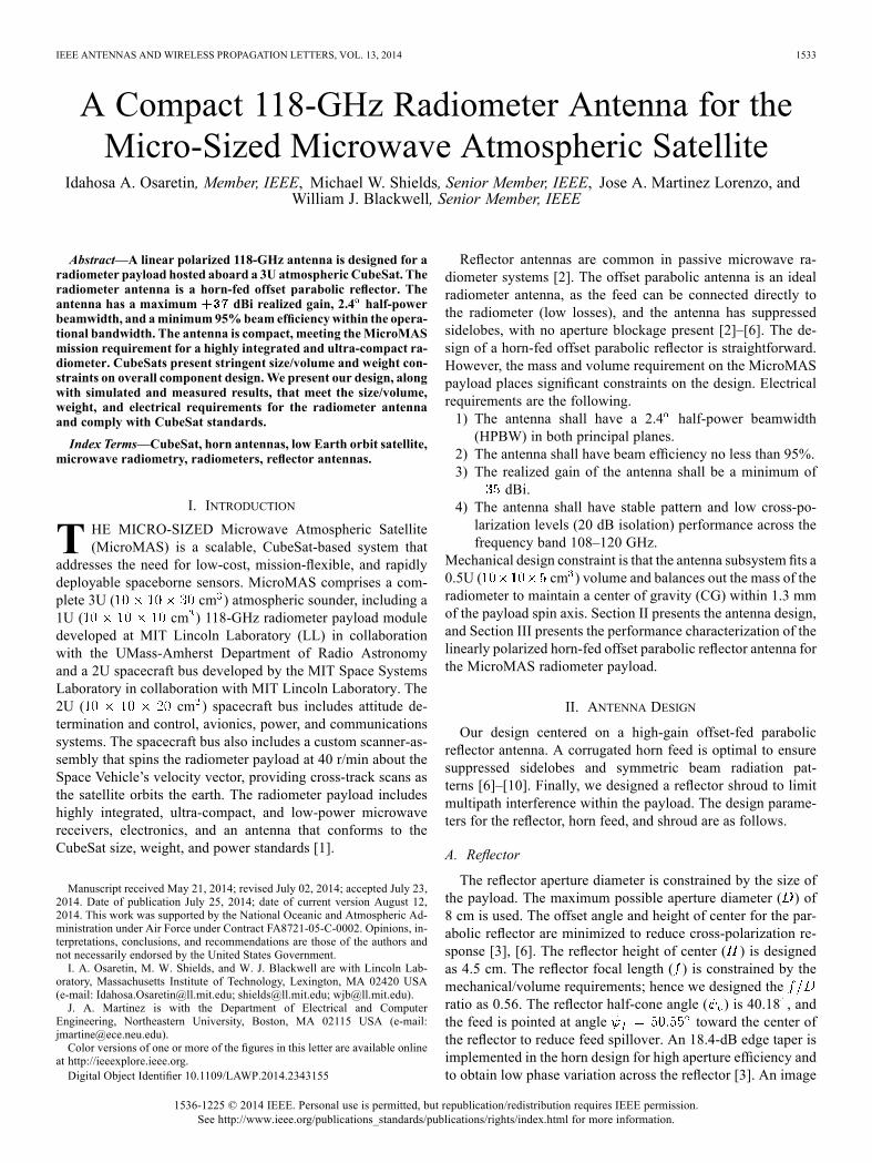
addresses the need for low-cost, mission-flexible, and rapidlydeployable spaceborne sensors. MicroMAS comprises a com-plete 3U ( cm ) atmospheric sounder, including a1U ( cm ) 118-GHz radiometer payload moduledeveloped at MIT Lincoln Laboratory (LL) in collaborationwith the UMass-Amherst Department of Radio Astronomyand a 2U spacecraft bus developed by the MIT Space SystemsLaboratory in collaboration with MIT Lincoln Laboratory. The2U ( cm ) spacecraft bus includes attitude de-termination and control, avionics, power, and communicationssystems. The spacecraft bus also includes a custom scanner-as-sembly that spins the radiometer payload at 40 r/min about theSpace Vehicle’s velocity vector, providing cross-track scans asthe satellite orbits the earth. The radiometer payload includeshighly integrated, ultra-compact, and low-power microwavereceivers, electronics, and an antenna that conforms to theCubeSat size, weight, and power standards [1].
Manuscript received May 21, 2014; revised July 02, 2014; accepted July 23,2014. Date of publication July 25, 2014; date of current version August 12,2014. This work was supported by the National Oceanic and Atmospheric Ad-ministration under Air Force under Contract FA8721-05-C-0002. Opinions, in-terpretations, conclusions, and recommendations are those of the authors andnot necessarily endorsed by the United States Government.I. A. Osaretin, M. W. Shields, and W. J. Blackwell are with Lincoln Lab-
oratory, Massachusetts Institute of Technology, Lexington, MA 02420 USA(e-mail: [email protected]; [email protected]; [email protected]).J. A. Martinez is with the Department of Electrical and Computer
Engineering, Northeastern University, Boston, MA 02115 USA (e-mail:[email protected]).Color versions of one or more of the figures in this letter are available online
at http://ieeexplore.ieee.org.Digital Object Identifier 10.1109/LAWP.2014.2343155
Reflector antennas are common in passive microwave ra-diometer systems [2]. The offset parabolic antenna is an idealradiometer antenna, as the feed can be connected directly tothe radiometer (low losses), and the antenna has suppressedsidelobes, with no aperture blockage present [2]–[6]. The de-sign of a horn-fed offset parabolic reflector is straightforward.However, the mass and volume requirement on the MicroMASpayload places significant constraints on the design. Electricalrequirements are the following.1) The antenna shall have a 2.4 half-power beamwidth(HPBW) in both principal planes.
2) The antenna shall have beam efficiency no less than 95%.3) The realized gain of the antenna shall be a minimum of
dBi.4) The antenna shall have stable pattern and low cross-po-larization levels (20 dB isolation) performance across thefrequency band 108–120 GHz.
Mechanical design constraint is that the antenna subsystem fits a0.5U ( cm ) volume and balances out the mass of theradiometer to maintain a center of gravity (CG) within 1.3 mmof the payload spin axis. Section II presents the antenna design,and Section III presents the performance characterization of thelinearly polarized horn-fed offset parabolic reflector antenna forthe MicroMAS radiometer payload.
II. ANTENNA DESIGN
Our design centered on a high-gain offset-fed parabolicreflector antenna. A corrugated horn feed is optimal to ensuresuppressed sidelobes and symmetric beam radiation pat-terns [6]–[10]. Finally, we designed a reflector shroud to limitmultipath interference within the payload. The design parame-ters for the reflector, horn feed, and shroud are as follows.
A. Reflector
The reflector aperture diameter is constrained by the size ofthe payload. The maximum possible aperture diameter ( ) of8 cm is used. The offset angle and height of center for the par-abolic reflector are minimized to reduce cross-polarization re-sponse [3], [6]. The reflector height of center ( ) is designedas 4.5 cm. The reflector focal length ( ) is constrained by themechanical/volume requirements; hence we designed theratio as 0.56. The reflector half-cone angle ( ) is 40.18 , andthe feed is pointed at angle toward the center ofthe reflector to reduce feed spillover. An 18.4-dB edge taper isimplemented in the horn design for high aperture efficiency andto obtain low phase variation across the reflector [3]. An image
1536-1225 © 2014 IEEE. Personal use is permitted, but republication/redistribution requires IEEE permission.See http://www.ieee.org/publications_standards/publications/rights/index.html for more information.
1534 IEEE ANTENNAS AND WIRELESS PROPAGATION LETTERS, VOL. 13, 2014
Fig. 1. Computer-aided design (CAD) rendition of the MicroMAS spacevehicle.
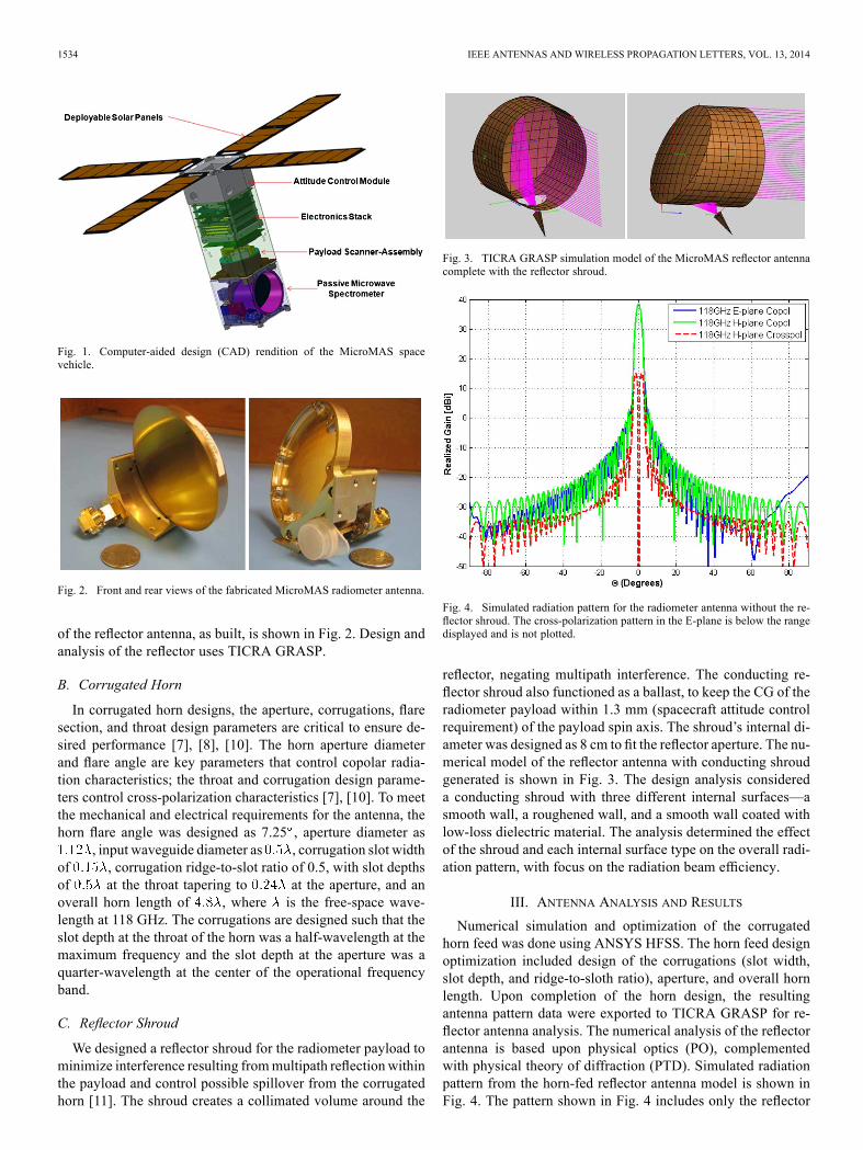
Fig. 2. Front and rear views of the fabricated MicroMAS radiometer antenna.
of the reflector antenna, as built, is shown in Fig. 2. Design andanalysis of the reflector uses TICRA GRASP.
B. Corrugated Horn
In corrugated horn designs, the aperture, corrugations, flaresection, and throat design parameters are critical to ensure de-sired performance [7], [8], [10]. The horn aperture diameterand flare angle are key parameters that control copolar radia-tion characteristics; the throat and corrugation design parame-ters control cross-polarization characteristics [7], [10]. To meetthe mechanical and electrical requirements for the antenna, thehorn flare angle was designed as 7.25 , aperture diameter as
, input waveguide diameter as , corrugation slot widthof , corrugation ridge-to-slot ratio of 0.5, with slot depthsof at the throat tapering to at the aperture, and anoverall horn length of , where is the free-space wave-length at 118 GHz. The corrugations are designed such that theslot depth at the throat of the horn was a half-wavelength at themaximum frequency and the slot depth at the aperture was aquarter-wavelength at the center of the operational frequencyband.
C. Reflector Shroud
We designed a reflector shroud for the radiometer payload tominimize interference resulting frommultipath reflection withinthe payload and control possible spillover from the corrugatedhorn [11]. The shroud creates a collimated volume around the
Fig. 3. TICRA GRASP simulation model of the MicroMAS reflector antennacomplete with the reflector shroud.
Fig. 4. Simulated radiation pattern for the radiometer antenna without the re-flector shroud. The cross-polarization pattern in the E-plane is below the rangedisplayed and is not plotted.
reflector, negating multipath interference. The conducting re-flector shroud also functioned as a ballast, to keep the CG of theradiometer payload within 1.3 mm (spacecraft attitude controlrequirement) of the payload spin axis. The shroud’s internal di-ameter was designed as 8 cm to fit the reflector aperture. The nu-merical model of the reflector antenna with conducting shroudgenerated is shown in Fig. 3. The design analysis considereda conducting shroud with three different internal surfaces—asmooth wall, a roughened wall, and a smooth wall coated withlow-loss dielectric material. The analysis determined the effectof the shroud and each internal surface type on the overall radi-ation pattern, with focus on the radiation beam efficiency.
III. ANTENNA ANALYSIS AND RESULTS
Numerical simulation and optimization of the corrugatedhorn feed was done using ANSYS HFSS. The horn feed designoptimization included design of the corrugations (slot width,slot depth, and ridge-to-sloth ratio), aperture, and overall hornlength. Upon completion of the horn design, the resultingantenna pattern data were exported to TICRA GRASP for re-flector antenna analysis. The numerical analysis of the reflectorantenna is based upon physical optics (PO), complementedwith physical theory of diffraction (PTD). Simulated radiationpattern from the horn-fed reflector antenna model is shown inFig. 4. The pattern shown in Fig. 4 includes only the reflector
OSARETIN et al.: COMPACT 118-GHz RADIOMETER ANTENNA 1535
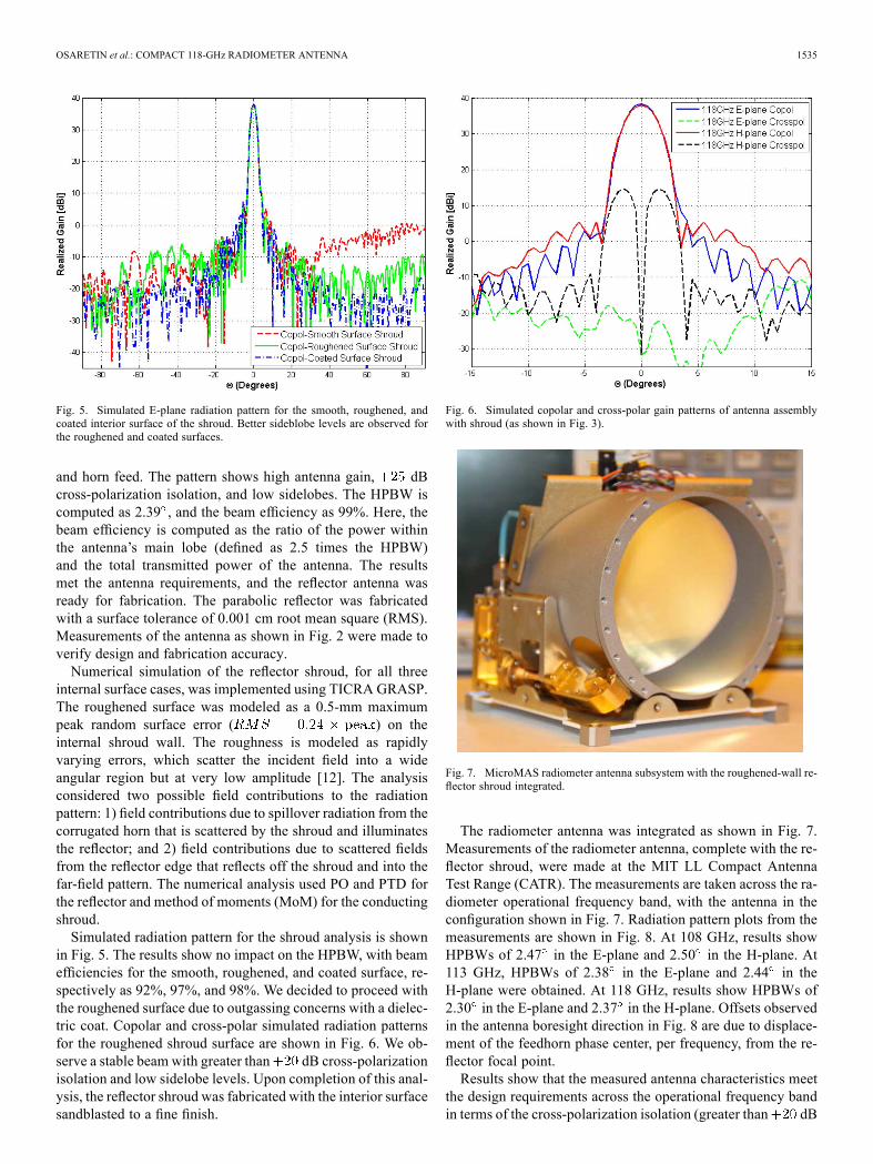
Fig. 5. Simulated E-plane radiation pattern for the smooth, roughened, andcoated interior surface of the shroud. Better sideblobe levels are observed forthe roughened and coated surfaces.
and horn feed. The pattern shows high antenna gain, dBcross-polarization isolation, and low sidelobes. The HPBW iscomputed as 2.39 , and the beam efficiency as 99%. Here, thebeam efficiency is computed as the ratio of the power withinthe antenna’s main lobe (defined as 2.5 times the HPBW)and the total transmitted power of the antenna. The resultsmet the antenna requirements, and the reflector antenna wasready for fabrication. The parabolic reflector was fabricatedwith a surface tolerance of 0.001 cm root mean square (RMS).Measurements of the antenna as shown in Fig. 2 were made toverify design and fabrication accuracy.Numerical simulation of the reflector shroud, for all three
internal surface cases, was implemented using TICRA GRASP.The roughened surface was modeled as a 0.5-mm maximumpeak random surface error ( ) on theinternal shroud wall. The roughness is modeled as rapidlyvarying errors, which scatter the incident field into a wideangular region but at very low amplitude [12]. The analysisconsidered two possible field contributions to the radiationpattern: 1) field contributions due to spillover radiation from thecorrugated horn that is scattered by the shroud and illuminatesthe reflector; and 2) field contributions due to scattered fieldsfrom the reflector edge that reflects off the shroud and into thefar-field pattern. The numerical analysis used PO and PTD forthe reflector and method of moments (MoM) for the conductingshroud.Simulated radiation pattern for the shroud analysis is shown
in Fig. 5. The results show no impact on the HPBW, with beamefficiencies for the smooth, roughened, and coated surface, re-spectively as 92%, 97%, and 98%. We decided to proceed withthe roughened surface due to outgassing concerns with a dielec-tric coat. Copolar and cross-polar simulated radiation patternsfor the roughened shroud surface are shown in Fig. 6. We ob-serve a stable beam with greater than dB cross-polarizationisolation and low sidelobe levels. Upon completion of this anal-ysis, the reflector shroud was fabricated with the interior surfacesandblasted to a fine finish.
Fig. 6. Simulated copolar and cross-polar gain patterns of antenna assemblywith shroud (as shown in Fig. 3).
Fig. 7. MicroMAS radiometer antenna subsystem with the roughened-wall re-flector shroud integrated.
The radiometer antenna was integrated as shown in Fig. 7.Measurements of the radiometer antenna, complete with the re-flector shroud, were made at the MIT LL Compact AntennaTest Range (CATR). The measurements are taken across the ra-diometer operational frequency band, with the antenna in theconfiguration shown in Fig. 7. Radiation pattern plots from themeasurements are shown in Fig. 8. At 108 GHz, results showHPBWs of 2.47 in the E-plane and 2.50 in the H-plane. At113 GHz, HPBWs of 2.38 in the E-plane and 2.44 in theH-plane were obtained. At 118 GHz, results show HPBWs of2.30 in the E-plane and 2.37 in the H-plane. Offsets observedin the antenna boresight direction in Fig. 8 are due to displace-ment of the feedhorn phase center, per frequency, from the re-flector focal point.Results show that the measured antenna characteristics meet
the design requirements across the operational frequency bandin terms of the cross-polarization isolation (greater than dB
1536 IEEE ANTENNAS AND WIRELESS PROPAGATION LETTERS, VOL. 13, 2014
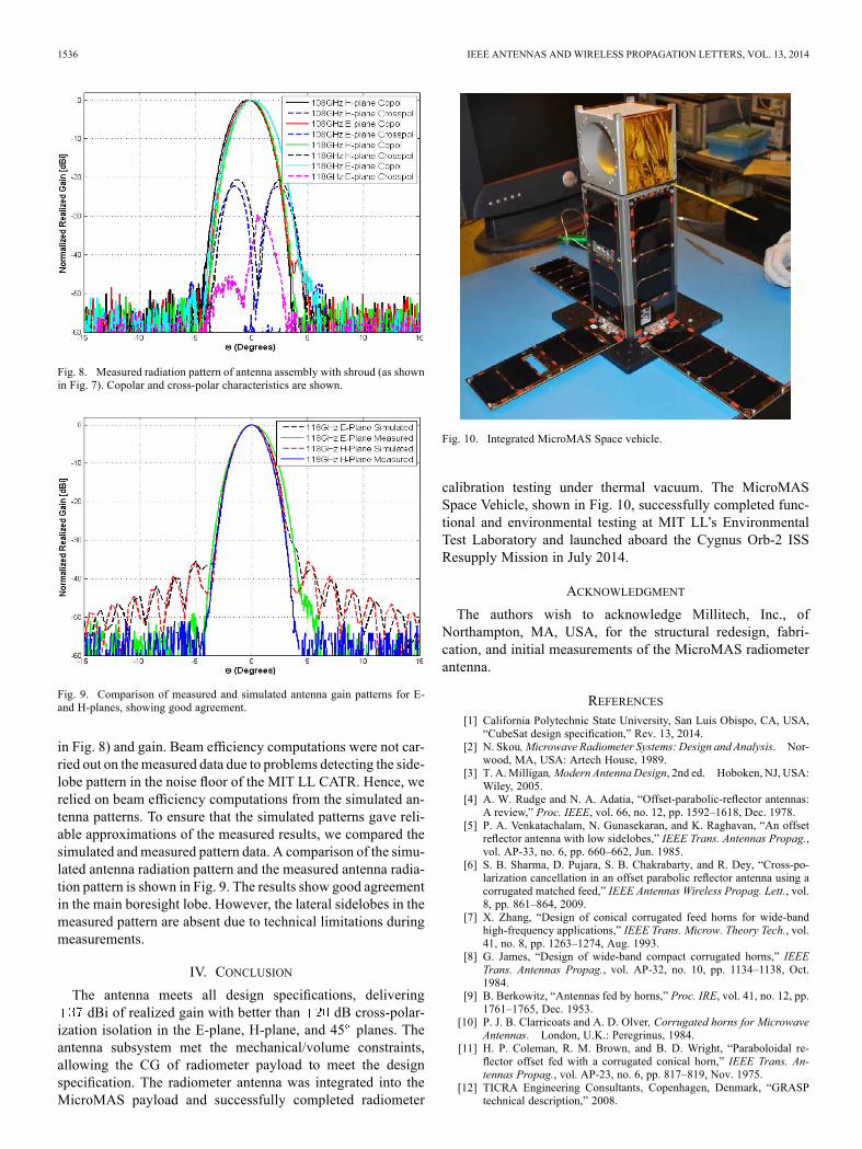
Fig. 8. Measured radiation pattern of antenna assembly with shroud (as shownin Fig. 7). Copolar and cross-polar characteristics are shown.
Fig. 9. Comparison of measured and simulated antenna gain patterns for E-and H-planes, showing good agreement.
in Fig. 8) and gain. Beam efficiency computations were not car-ried out on themeasured data due to problems detecting the side-lobe pattern in the noise floor of the MIT LL CATR. Hence, werelied on beam efficiency computations from the simulated an-tenna patterns. To ensure that the simulated patterns gave reli-able approximations of the measured results, we compared thesimulated andmeasured pattern data. A comparison of the simu-lated antenna radiation pattern and the measured antenna radia-tion pattern is shown in Fig. 9. The results show good agreementin the main boresight lobe. However, the lateral sidelobes in themeasured pattern are absent due to technical limitations duringmeasurements.
IV. CONCLUSION
The antenna meets all design specifications, deliveringdBi of realized gain with better than dB cross-polar-
ization isolation in the E-plane, H-plane, and 45 planes. Theantenna subsystem met the mechanical/volume constraints,allowing the CG of radiometer payload to meet the designspecification. The radiometer antenna was integrated into theMicroMAS payload and successfully completed radiometer
Fig. 10. Integrated MicroMAS Space vehicle.
calibration testing under thermal vacuum. The MicroMASSpace Vehicle, shown in Fig. 10, successfully completed func-tional and environmental testing at MIT LL’s EnvironmentalTest Laboratory and launched aboard the Cygnus Orb-2 ISSResupply Mission in July 2014.
ACKNOWLEDGMENT
The authors wish to acknowledge Millitech, Inc., ofNorthampton, MA, USA, for the structural redesign, fabri-cation, and initial measurements of the MicroMAS radiometerantenna.
REFERENCES[1] California Polytechnic State University, San Luis Obispo, CA, USA,
“CubeSat design specification,” Rev. 13, 2014.[2] N. Skou, Microwave Radiometer Systems: Design and Analysis. Nor-
wood, MA, USA: Artech House, 1989.[3] T. A.Milligan, Modern Antenna Design, 2nd ed. Hoboken, NJ, USA:
Wiley, 2005.[4] A. W. Rudge and N. A. Adatia, “Offset-parabolic-reflector antennas:
A review,” Proc. IEEE, vol. 66, no. 12, pp. 1592–1618, Dec. 1978.[5] P. A. Venkatachalam, N. Gunasekaran, and K. Raghavan, “An offset
reflector antenna with low sidelobes,” IEEE Trans. Antennas Propag.,vol. AP-33, no. 6, pp. 660–662, Jun. 1985.
[6] S. B. Sharma, D. Pujara, S. B. Chakrabarty, and R. Dey, “Cross-po-larization cancellation in an offset parabolic reflector antenna using acorrugated matched feed,” IEEE Antennas Wireless Propag. Lett., vol.8, pp. 861–864, 2009.
[7] X. Zhang, “Design of conical corrugated feed horns for wide-bandhigh-frequency applications,” IEEE Trans. Microw. Theory Tech., vol.41, no. 8, pp. 1263–1274, Aug. 1993.
[8] G. James, “Design of wide-band compact corrugated horns,” IEEETrans. Antennas Propag., vol. AP-32, no. 10, pp. 1134–1138, Oct.1984.
[9] B. Berkowitz, “Antennas fed by horns,” Proc. IRE, vol. 41, no. 12, pp.1761–1765, Dec. 1953.
[10] P. J. B. Clarricoats and A. D. Olver, Corrugated horns for MicrowaveAntennas. London, U.K.: Peregrinus, 1984.
[11] H. P. Coleman, R. M. Brown, and B. D. Wright, “Paraboloidal re-flector offset fed with a corrugated conical horn,” IEEE Trans. An-tennas Propag., vol. AP-23, no. 6, pp. 817–819, Nov. 1975.
[12] TICRA Engineering Consultants, Copenhagen, Denmark, “GRASPtechnical description,” 2008.