ieee 802.16.4-01/12r1 802.16b phy strawman page 1 of 51 · ieee 802.16.4-01/12r1 802.16b phy...
TRANSCRIPT

IEEE 802.16.4-01/12r1 802.16b PHY strawman Page 1 of 51
June 5, 2001, 12:52 PM 802.16.4 - PHY Editing team 802164-01_15.doc
1. Notations ............................................................................................................................................................................ 32. Introduction (Octavian) ..................................................................................................................................................... 33. Time and frequency description (Nico — Editing team)................................................................................................... 4
3.1. Frequency description ............................................................................................................................................... 43.1.1. Carrier allocation for 64-FFT ........................................................................................................................... 43.1.2. Carrier allocation for 256-FFT ......................................................................................................................... 43.1.3. Carrier allocation of 2048-FFT (optional) ....................................................................................................... 5
3.1.3.1. Downlink................................................................................................................................................... 53.1.3.1.1 Frame structure ...................................................................................................................................... 53.1.3.1.2 Symbol Structure ................................................................................................................................... 5
3.1.3.2. Uplink........................................................................................................................................................ 73.1.3.2.1 Subchannel description.......................................................................................................................... 73.1.3.2.2 Framing Structure .................................................................................................................................. 83.1.3.2.3 Symbol Structure ................................................................................................................................... 9
3.2. Time description...................................................................................................................................................... 103.3. Frame and burst structure........................................................................................................................................ 10
3.3.1. Downlink and uplink bursts............................................................................................................................ 113.3.2. OFDM Preambles — network entry, ranging, AGC, synchronization and equalization............................... 12
3.3.2.1. Network entry ......................................................................................................................................... 123.3.2.2. Time and Power Ranging of the users ................................................................................................... 13
3.3.2.2.1 Ranging using an OFDMA mapping .................................................................................................. 133.3.2.2.2 Ranging using an OFDM mapping ..................................................................................................... 15
3.3.2.3. Bandwidth request .................................................................................................................................. 153.3.3. Bandwidth Requesting.................................................................................................................................... 15
3.3.3.1. Fast bandwidth requests using an OFDMA mapping............................................................................ 153.3.3.2. Bandwidth requests using an OFDM mapping...................................................................................... 15
4. Data encoding (Octavian- Brian, Editing Team)............................................................................................................ 164.1. Data randomizer (scrambler) .................................................................................................................................. 164.2. Forward error correction ......................................................................................................................................... 16
4.2.1. Concatenated Reed-Solomon.......................................................................................................................... 164.2.1.1. Reed Solomon encoding......................................................................................................................... 174.2.1.2. Convolutional encoding.......................................................................................................................... 174.2.1.3. Block Lengths and Concatenated Code Rates ....................................................................................... 18
4.2.2. Optional convolutional encoder...................................................................................................................... 184.2.2.1. Convolutional encoder............................................................................................................................ 19
4.3. Bit interleaving ........................................................................................................................................................ 214.3.1. Bit interleaving for OFDM modes (64-FFT and 256-FFT)........................................................................... 214.3.2. Bit interleaving for optional OFDMA mode.................................................................................................. 21
4.4. Optional FEC and interleaving - Block Turbo Coding.......................................................................................... 224.4.1. Proposed Block Turbo Codes ......................................................................................................................... 22
4.4.1.1. Block Turbo Constituent Codes ............................................................................................................. 224.4.1.2. Overall Turbo Product Codes................................................................................................................. 22
4.4.2. Turbo Code Description.................................................................................................................................. 234.4.2.1. Encoding of a Turbo Product Code........................................................................................................ 244.4.2.2. Example of a 2-Dimesional Product Code ............................................................................................ 244.4.2.3. 3-Dimensional TPC Encoding ............................................................................................................... 254.4.2.4. Shortened TPCs ...................................................................................................................................... 264.4.2.5. Example of a Shortened 2-Dimensional TPC........................................................................................ 264.4.2.6. Example of a Shortened 3-Dimensional TPC........................................................................................ 274.4.2.7. Iterative Decoding................................................................................................................................... 28
4.4.3. Referecences.................................................................................................................................................... 314.5. Optional FEC and interleaving - Convolutional Turbo Codes .............................................................................. 31
4.5.1. Termination ..................................................................................................................................................... 314.5.2. Code Rates and Puncturing............................................................................................................................. 324.5.3. Code Permuter................................................................................................................................................. 324.5.4. Channel Interleaver ......................................................................................................................................... 324.5.5. CRC ................................................................................................................................................................. 33
IEEE 802.16.4-01/12r1 802.16b PHY strawman Page 2 of 51
June 5, 2001, 12:52 PM 802.16.4 - PHY Editing team 802164-01_15.doc
5. Constellation Mapping (Yossi — Editing Team)............................................................................................................. 335.1. Data Modulation...................................................................................................................................................... 335.2. Pilot Modulation...................................................................................................................................................... 355.3. Ranging Pilot Modulation....................................................................................................................................... 36
6. RF Characteristics (Drayt, — Nico, Editing Team)........................................................................................................ 366.1. Regulatory Requirements........................................................................................................................................ 36
6.1.1. Introduction ..................................................................................................................................................... 366.1.2. FCC Regulatory issues.................................................................................................................................... 366.1.3. ETSI Regulatory issues................................................................................................................................... 36
6.2. Channelization......................................................................................................................................................... 366.2.1. Channel Numbering ........................................................................................................................................ 366.2.2. Valid operating channels ................................................................................................................................ 37
6.3. Transmitter Requirements....................................................................................................................................... 376.3.1. Transmit Spectrum Mask................................................................................................................................ 376.3.2. Transmit power levels..................................................................................................................................... 386.3.3. Transmit Power Level Control ....................................................................................................................... 386.3.4. Transmitter Linearity ...................................................................................................................................... 386.3.5. Transmitter Spectral Flatness ......................................................................................................................... 386.3.6. Transmitter Constellation Error and Test Method......................................................................................... 39
6.4. Receiver Requirements ........................................................................................................................................... 396.4.1. Receiver Sensitivity ........................................................................................................................................ 396.4.2. Receiver Adjacent and Alternate Channel Rejection .................................................................................... 396.4.3. Receiver Interference Requirements .............................................................................................................. 406.4.4. Receiver Maximum Input Signal.................................................................................................................... 406.4.5. Receiver Linearity........................................................................................................................................... 406.4.6. Receiver Gain Control and RSSI Parameters ............................................................................................... 406.4.7. Receiver Diversity (optional feature) ............................................................................................................. 40
6.5. Frequency Control Requirements ........................................................................................................................... 406.5.1. Transmit/Receive Center Frequency and Symbol Clock Frequency Tolerance........................................... 406.5.2. Frequency Lock Detect ................................................................................................................................... 416.5.3. Phase Noise ..................................................................................................................................................... 41
6.6. General Requirements ............................................................................................................................................. 416.6.1. Temperature Range ......................................................................................................................................... 416.6.2. Antenna Interface............................................................................................................................................ 416.6.3. Indoor to Outdoor Unit Interface (Recommended Practice) ......................................................................... 416.6.4. Diagnosis Features .......................................................................................................................................... 41
7. Coexsitence in the middle UNII band - Interference and Mechanisms For Sharing the middle UNII band (LarryWatkins— Editing Team).......................................................................................................................................................... 41
7.1. General..................................................................................................................................................................... 417.2. EESS SAR interference requirement...................................................................................................................... 42
7.2.1. Antenna directivity to mitigate interference to EESS.................................................................................... 427.2.2. DFS to mitigate interference........................................................................................................................... 437.2.3. Transmitted power control to mitigate interference ...................................................................................... 437.2.4. Antenna polarization to mitigate interference................................................................................................ 437.2.5. Turning off Wireless HUMAN systems when a Spaceborne SAR is in the area......................................... 447.2.6. Other ways to mitigate interference ............................................................................................................... 44
8. Optional features for operation in cellular and sectorized environments (Octavian - Editing Team).......................... 448.1. Recommended practice for time synchronization in sectorized environments..................................................... 448.2. Recommended practice for time synchronization in cellular environments......................................................... 448.3. Recommended practice for power coordination in sectorized environments ....................................................... 448.4. Recommended practice for power coordination in cellular environments ........................................................... 458.5. Dynamic frequency selection in sectorized environments..................................................................................... 458.6. Dynamic frequency selection in cellular environments......................................................................................... 45
9. Ranging and Access schemes (call for comments) (Tal — Editing Team)..................................................................... 459.1. Subcarrier-based polling using on-off keying........................................................................................................ 459.2. Subcarrier-based polling using DBPSK ................................................................................................................. 46
10. Additional Possible Features (T.J. — Editing Team).................................................................................................. 4611. Annex A — Channel and Interference Model (Tal — Editing Team).......................................................................... 46

IEEE 802.16.4-01/12r1 802.16b PHY strawman Page 3 of 51
June 5, 2001, 12:52 PM 802.16.4 - PHY Editing team 802164-01_15.doc
11.1. Introduction ......................................................................................................................................................... 4611.2. Multipath channel................................................................................................................................................ 4711.3. Interference models ............................................................................................................................................. 48
11.3.1. Basic assumptions ........................................................................................................................................... 4911.3.2. Signal Wave shape .......................................................................................................................................... 4911.3.3. Generating Procedure...................................................................................................................................... 50
11.4. Radio Impairments .............................................................................................................................................. 5011.4.1. Power amplifier non-linearity (to add AM-PM distortion) ........................................................................... 5011.4.2. Phase noise ...................................................................................................................................................... 51
11.5. Acknowledgements ............................................................................................................................................. 5111.6. References ........................................................................................................................................................... 51
12. Annex B — MAC - PHY interface (Radu — Itzik, Jori, + Editing Team)................................................................... 51
Editing Team: Nico, Yossi, Tal, Bob, Minfei, T.J.Shan, Sanjay, Octavian, LarryOther editors: Drayt, Brian, Radu, Itzik, JoriEditor of the document: Octavian
1. Notations
Comments and TBD issues are marked using italics.
2. Introduction (Octavian)
The PHY layer described in this clause is designated for operation in the unlicensed frequency bands of 5-6 GHz. Inorder to allow different deployment scenarios from dense populated areas (where sectorized environments and the highinterference levels may require narrow channels) to sparse populated areas (where wider channels can help deliveringbetter services at the same system cost), the PHY layer is allowed to operate with channel bandwidths of 10 MHz or 20MHz and optionally 5 MHz. An 802.16b device must implement 10 MHz and/or 20 MHz channelization and mayimplement 5MHz channelization (see clause 6.2).
The PHY operation is based on OFDM (Orthogonal Frequency Division Multiplex) modulation and Time DivisionDuplexing (TDD). In OFDM the information is imposed onto the medium by modulating multiple carriers transmittedin parallel. As the modulation is often implemented using the FFT algorithm, the modes are designated by theminimum FFT size (called hereby FFT size), i.e. the next power of 2 above the number of used carriers. The PHYdefines two mandatory modes 64 and 256 —FFT and one optional mode 2048-FFT. The mandatory modes employ TimeDivision Multiple Access (TDMA) while the optional mode employs a combination of TDMA and OrthogonalFrequency Division Multiple Access (OFDMA). The modes are summarized in Table 1.
Mode Access method FFT size Status64-FFT TDMA 64 Mandatory256-FFT TDMA 256 Mandatory2048-FFT OFDMA 2048 Optional
Table 1: Mandatory and optional modes
To be standard compliant, a system must implement both the 64-FFT and the 256-FFT modes.
Notes: changes to this sections where made to reflect the latest group decisions on channel bandwidth and FFT sizes.
IEEE 802.16.4-01/12r1 802.16b PHY strawman Page 4 of 51
June 5, 2001, 12:52 PM 802.16.4 - PHY Editing team 802164-01_15.doc
3. Time and frequency description (Nico — Editing team)
3.1. Frequency description
An OFDM symbol in the frequency domain consists of orthogonal carriers. An Inverse Fourier Transform is used to
transform this signal into the time domain. The following three types of carriers are distinguished:
• Data carriers — Carriers used to modulate data symbols on.• Pilot carriers — Carriers used for estimation purposes• Null carriers — Carriers that remain unused to provide guard bands and DC carrier.
The purpose of the guard bands is to enable the signal to naturally decay within the desired spectral mask. Byconvention, carrier 0 is the DC carrier and it is not used. Other carriers are numbered in their relative position to the DC
carrier, using positive incrementation for the adjacent carrier with higher frequency.
Fclock = clock frequency at output of IFFT
BW = channel bandwidth (20, 10, and optionally 5MHZ) (see clause 6.2)
FFT sizes: 64, 256 and optionally 2048
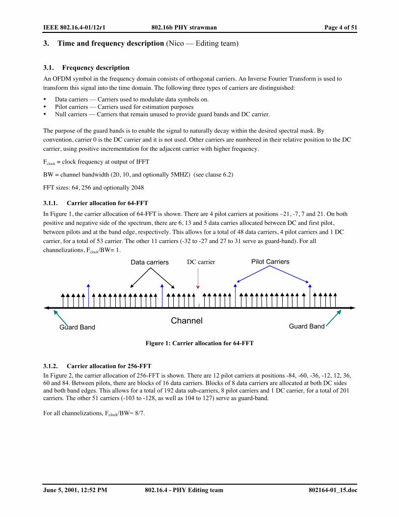
3.1.1. Carrier allocation for 64-FFT
In Figure 1, the carrier allocation of 64-FFT is shown. There are 4 pilot carriers at positions –21, -7, 7 and 21. On bothpositive and negative side of the spectrum, there are 6, 13 and 5 data carries allocated between DC and first pilot,
between pilots and at the band edge, respectively. This allows for a total of 48 data carriers, 4 pilot carriers and 1 DC
carrier, for a total of 53 carrier. The other 11 carriers (-32 to -27 and 27 to 31 serve as guard-band). For allchannelizations, Fclock/BW= 1.
Data carriers
Channel
Pilot Carriers
Guard Band Guard Band
DC carrier
Figure 1: Carrier allocation for 64-FFT
3.1.2. Carrier allocation for 256-FFT
In Figure 2, the carrier allocation of 256-FFT is shown. There are 12 pilot carriers at positions -84, -60, -36, -12, 12, 36,60 and 84. Between pilots, there are blocks of 16 data carriers. Blocks of 8 data carriers are allocated at both DC sidesand both band edges. This allows for a total of 192 data sub-carriers, 8 pilot carriers and 1 DC carrier, for a total of 201carriers. The other 51 carriers (-103 to -128, as well as 104 to 127) serve as guard-band.
For all channelizations, Fclock/BW= 8/7.

IEEE 802.16.4-01/12r1 802.16b PHY strawman Page 5 of 51
June 5, 2001, 12:52 PM 802.16.4 - PHY Editing team 802164-01_15.doc
Pilot CarriersData carriers
ChannelGuard Band Guard Band
DC carrier
Figure 2: Carrier allocation for 256-FFT
3.1.3. Carrier allocation of 2048-FFT (optional)
Note that carrier numbering for 2k is 1 max, while 64 and 256 FFT have carrier numbering -max +maxIn the 2048-FFT mode, a different allocation is used in the up- and down-link. This is motivated by the intend toefficiently facilitate OFDMA. For all channelizations, Fclock/BW= 8/7.
3.1.3.1. Downlink
3.1.3.1.1 Frame structure
The transmission of the DL is performed on one or more subchannels of the OFDMA symbol. A DL sub-channel
constitutes 48 (non-consecutive) data carriers. The mapping of the subchannels is performed in a two-dimensional grid,involving the subchannels in the frequency domain and OFDM symbols in the time domain. Figure 3 illustrates a
possible two-dimensional transmission mapping (every color represents a different Modulation and coding scheme).
Time
Freq
uenc
y
OFDMAsymbol time
PHYControl+ Uplink
MAP
Carrier-Group
NSymbols
Figure 3: Map II, DL framing
3.1.3.1.2 Symbol Structure
The symbol structure made up of constant and variable location pilots, which are spread all over the symbol, and fromdata carriers, which are divided into subchannels.

IEEE 802.16.4-01/12r1 802.16b PHY strawman Page 6 of 51
June 5, 2001, 12:52 PM 802.16.4 - PHY Editing team 802164-01_15.doc
First allocating the pilots and then mapping the rest of the carriers to Sub-Channels construct the OFDMA symbol.There are two kinds of pilots in the OFDM symbol:
• Constant location pilots - Transmitted every symbol• Variable location pilots — Location shifted with a cyclic appearance of 4 OFDM symbols
The variable pilots are inserted in the locations defined by the next formula:
VPLk *12*3 +=
k Indices from 0 to the number of Overall Usable Carriers minus 13..0L denotes the OFDM symbol number with a cyclic period of 4, with order: 0,2,1,3
0?vP is an integer number
The pilot s locations are illustrated in Figure 4:
Data CarrierVariable Location Pilot CarrierConstant Location Pilot Carrier
Frequency
Tim
e
L=0
L=1
L=2
L=3
3
12Max Carrier
Used
15
6
9
0
Figure 4: Pilots and data carrier location in the DL OFDMA symbol
The symbols are transmitted with the following order L=0,2,1,3.After mapping the pilots, the rest of the carriers (not including the DC carrier, which is not used) are data carriersscattered all over the usable spectrum (we should mention that the exact location of those carriers changes as a functionof the symbol number which is modulo 4).
Using special permutation code, which is based upon the procedure described below, does the allocation of carriers toSub-Channels (see also Annex EDITOR_TG3_REFERENCE). CellId is a MAC defined parameter, defining thecurrent cell identification numbers, to support different cells.
1. The usable carrier space is divided into GroupsN basic groups. The number of basic groups,
GroupsN , is equal
to the number of data carriers per subchannel (48 in DL and 53 in UL). Each basic group is made up ofadjunct carriers. The number of the carriers in a basic group is equal to the number of possible subchannels.As a result of the carrier allocation procedure, each subchannel is built taking one carrier from each basicgroup.
2. We define a basic permutation { }0nBasePermutatio , containing elementsN elements. elementsN is equal to
the number of possible subchannels. Different permutations ({ }CellIdSeriesPermutated ) are achieved by
cyclically rotating CellId times the { }0nBasePermutatio to the left.
3. To get a ChannelSubN − length series ( ChannelSubN − being the number of data carriers per subchannel) the
permutated series are concatenated, until the concatenated series has at least ChannelSubN − elements.

IEEE 802.16.4-01/12r1 802.16b PHY strawman Page 7 of 51
June 5, 2001, 12:52 PM 802.16.4 - PHY Editing team 802164-01_15.doc
4. Let ][ jps (j starting from 0) be the j -th element of { }CellIdSeriesPermutated . The k-th element of the
resulting concatenated series, ][kcs is obtained by:
{ })mod()mod( ]/)1[(ceil][][
elementselements NelemensNss CellIdNkkpkc ?++=
5. The last step achieves the carrier numbers allocated for the specific Sub-Channel with the current CellId.
Using the next formula we achieve the ChannelSubN − carriers (48 in DL, 53 in UL) of the current permutation
in the cell:
carrier(n, s) = N_elements*n + c_s[n] - 1024.
Here carrier(n, s) is the n-th carrier of subchannel number s; n = 0,1..., 1−−ChannelSubN .
Parameter Value
FFTN 2048 (2K)
usedN 1703
Guard Carriers: Left, Right 172 172Subchannels: nr, data carriers/subchannel 32 48BasicConstantLocationPilots {0, 39, 261, 330, 342, 351, 522, 642, 645, 651, 708, 726,
756, 792, 849, 855, 918, 1017, 1143, 1155, 1158, 1185,1206, 1260, 1407, 1419,1428, 1461, 1530,1545, 1572,1701, 1702}-1024
PermutationBase0 {3, 18, 2, 8, 16, 10, 11, 15, 26, 22, 6, 9, 27, 20, 25, 1, 29,7, 21, 5, 28, 31, 23, 17, 4, 24, 0, 13, 12, 19, 14, 30}
Table 2: Downlink parameters
3.1.3.2. Uplink
3.1.3.2.1 Subchannel description
The next section gives a description of the structure of a subchannel. A subchannel is made up of 48 usable carriers and5 pilot carriers. The DL transmission for these modes is also made of subchannel transmissions, but the Sub-Channel ismade up of 48 data carriers only, while pilot carriers are spread all over the OFDMA symbol, to be used for channelestimation. The UL subchannel structure is shown in Error! Reference source not found..
Data CarrierVariable Location Pilot Carrier
Frequency
Tim
e
L=0
L=2
L=11
13
2
11
0 26 40
15 29 42
38 51
Constant Location Pilot Carrier
Figure 5: Allocation of data and pilot carriers for a UL Sub-Channel
IEEE 802.16.4-01/12r1 802.16b PHY strawman Page 8 of 51
June 5, 2001, 12:52 PM 802.16.4 - PHY Editing team 802164-01_15.doc
The UL data symbol structure is comprised of data carriers and pilot carriers. The data symbols are produced with amodulo 13 repetition (L denotes the modulo 13 index of the symbol with indices 0..12), the location of the variablelocation pilots are shifted for every symbol produced, the first symbol (L=0) is produced after the all-pilot symbols(preamble). For L=0 the variable location pilots are positioned within the subchannel at indices: 0,13, 27,40 for other Lthese location vary by addition of L to those position, for example for L=5 variable pilots location are: 5,18, 32, 45. theUL Sub-Channel is also comprised of a constant pilot at the index 26. all other carriers (48) are data carriers, theirlocation changes for every L, the transmission ordering of L is 0,2,4,6,8,10,12,1,3,5,7,9,11.
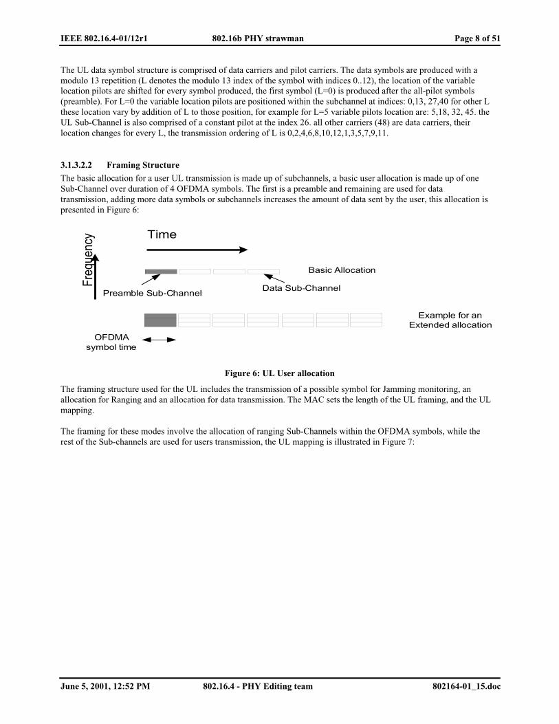
3.1.3.2.2 Framing Structure
The basic allocation for a user UL transmission is made up of subchannels, a basic user allocation is made up of oneSub-Channel over duration of 4 OFDMA symbols. The first is a preamble and remaining are used for datatransmission, adding more data symbols or subchannels increases the amount of data sent by the user, this allocation ispresented in Figure 6:
Time
Freq
uenc
y
OFDMAsymbol time
Basic Allocation
Preamble Sub-ChannelData Sub-Channel
Example for anExtended allocation
Figure 6: UL User allocation
The framing structure used for the UL includes the transmission of a possible symbol for Jamming monitoring, anallocation for Ranging and an allocation for data transmission. The MAC sets the length of the UL framing, and the ULmapping.
The framing for these modes involve the allocation of ranging Sub-Channels within the OFDMA symbols, while therest of the Sub-channels are used for users transmission, the UL mapping is illustrated in Figure 7:

IEEE 802.16.4-01/12r1 802.16b PHY strawman Page 9 of 51
June 5, 2001, 12:52 PM 802.16.4 - PHY Editing team 802164-01_15.doc
Time
Freq
uenc
y
OFDMAsymbol time
Sub-Channel
Users allocatedSub-Channel
Ranging Sub-Channel
Optional NullSymbol
(Jammingmonitoring)
Figure 7: UL framing for 2k FFT
3.1.3.2.3 Symbol Structure
The symbol structure is made up of Sub-Channels, by their basic structure described in section Error! Referencesource not found.. There are several methods splitting the whole UL OFDMA symbol into Sub-Channels, the first twomethods are performed by first dividing the used carriers into basic groups (not including the DC carrier, which is notused), each containing a certain amount of carriers:
Then the following methods exist:
1. The number of basic groups is 53 (GroupsN =53) and they are allocated Y adjunct carriers, from the first
usable carrier to the last. Then special permutations are used to extract the Sub-Channels (the procedure to use
the permutation is defined in section ??, and each Sub-Channel is made up of 53 data carriers
ChannelSubN − =53).
2. Defining each basic group as a Sub-Channel, which implies that the number of carriers Y=53 and that thecarriers within the Sub-Channel are allocated adjunct. The carrier indices for each Sub-Channel are achievedusing the next formula:carrier(n, s) = 53*s + n -1024,
where carrier(n, s) is the n-th carrier of sub-channel number s; s = 0,1,...( elementsN -1); and n = 0, 1, ..., 52.
The last method for defining the Sub-Channels involves programming by MAC message the carrier numbers for each
Sub-Channel. When using method 1 (default) then the following parameters should be used:
1.
Parameter Value

IEEE 802.16.4-01/12r1 802.16b PHY strawman Page 10 of 51
June 5, 2001, 12:52 PM 802.16.4 - PHY Editing team 802164-01_15.doc
FFTN 2048 (2K)
usedN 1696
Guard Carriers: Left, Right 176 87Subchannels: nr, data carriers/subchannel 32 48PermutationBase0 {3, 18, 2, 8, 16, 10, 11, 15, 26, 22, 6, 9, 27, 20, 25, 1,
29, 7, 21, 5, 28, 31, 23, 17, 4, 24, 0, 13, 12, 19, 14,30} - 1024
Table 3: UL 2k parameters
Method 1 is the default method.
3.2. Time description
The Fourier transformed waveform is prepended with a circular extension of itself to form the guard-interval. The
extension is expressed as a fraction of the transformed waveform. Fractions of 1/4, 1/8, 1/16, 1/32 must be provided
with a minimum time-duration of 750 ns and a maximum time-duration of at most 6 µs. If a fraction provides a time-
duration below 750ns or above 6 µs for a given FFT size and channelization, this fraction does not have to be
implemented.
sampling 1 1 1/7 1 1/7BW(MHz) 64 256 1024
312 1/2 89 2/7 22 9/2882.81% 89.73% 94.87%3 1/5 11 1/5 44 4/5
1/32 1 2/51/16 7/10 2 4/51/8 1 2/5 5 3/51/4 4/5 2 4/5
156 1/4 44 9/14 11 9/56BWefficiency 82.81% 89.73% 94.87%
6 2/5 22 2/5 901/32 7/10 2 4/51/16 1 2/5 5 3/51/8 4/5 2 4/51/4 1 3/5 5 3/5
78 1/8 22 9/28 5 47/81BWefficiency 82.81% 89.73% 94.87%
12 4/5 44 4/5 179 1/51/32 1 2/5 5 3/51/16 4/5 2 4/51/8 1 3/5 5 3/51/4 3 1/5
FFT size
BWefficiency
20Tb (us)
Tg /Tb
Tg /Tb
5(Optional)
Tb (us)
Tb (us)
10
Tg /Tb
(kHz)f∆
(kHz)f∆
(kHz)f∆
Table 4: Frequency and Time parameters
3.3. Frame and burst structureIn the PMP mode, the frame structure is build from BS (downlink) and SS (uplink) transmissions. Each bursttransmission consists of one or more OFDM symbols. The cell radius is dependent on the time left open for randomsystem access. This time should at least equal the maximum tolerable round trip delay plus the number of OFDMsymbols necessary to transmit the ranging burst (see clause ??). Further, in each frame, the TX/RX transition gap(TTG) and RX/TX transition gap (RTG) need to be inserted between the downlink and uplink and at the end of eachframe respectively to allow the BS to turn around (time plan for a single frame is shown in Figure 8).

IEEE 802.16.4-01/12r1 802.16b PHY strawman Page 11 of 51
June 5, 2001, 12:52 PM 802.16.4 - PHY Editing team 802164-01_15.doc
PHY map
downstream upstream
TTG RTG
frame
frame
TG
PHY mapPMP mode
Mesh mode TG=max(TTG,RTG)+RTD /2max
TG TG
Figure 8: Frame structure
In the optional mesh mode, slots for several PHY maps are allocated and the frame structure is built from nodetransmissions. The cell radius is dependent on the Transition GAP (TG), which is inserted before every and after thelast PHY map. Between data-transmissions of different nodes, no delay need to be inserted. Random access uses thesame method as the PMP mode. The number of PHY maps in the mesh mode shall be a network management variable.
3.3.1. Downlink and uplink bursts
Preambles are special training sequences that are prepended to the OFDM symbols carrying data. The receiver usesthem for signal detection, AGC convergence, carrier recovery, symbol timing recovery and equalization. The PHY usesa fully featured preamble and shortened versions of it depending on the burst position in the frame. The completepreamble is depicted in Figure 9 and consists of multiple short training symbols and 1 long training symbol.
CB B B B B B B IB
tPREAMBLE
2Tsn Ts
n {1,2,3...}
Figure 9: Complete preamble structure
A short training symbol (B) has no cyclic prefix and consists of 12 carriers with an FFT size of 16 modulated by theelements of the sequence (to discuss the factor):
S16-7,7 = {0, 1+j, -1-j, 1+j, -1-j, -1-j, 1+j, 0, -1-j, -1-j, 1+j, 1+j, 1+j, 1+j, 0}
Equivalently, the same 12 carriers are spaced at 4 times the inter-carrier spacing with an FFT size of 64:
S16-31,31 = {0, 0, 0, 0, 0, 0, 0, 1+j, 0, 0, 0, -1-j, 0, 0, 0, 1+j, 0, 0, 0, -1-j, 0, 0, 0, -1-j, 0, 0, 0, 1+j, 0, 0, 0, 0, 0, 0, 0, -1-
j, 0, 0, 0, -1-j, 0, 0, 0, 1+j, 0, 0, 0, 1+j, 0, 0, 0, 1+j, 0, 0, 0, 1+j, 0, 0, 0, 0, 0, 0, 0}
and at 16 times the inter-carrier spacing with an FFT size of 256:
S16-127,127 = {0, 0, 0, 0, 0, 0, 0, 0, 0, 0, 0, 0, 0, 0, 0, 0, 1+j, 0, 0, 0, 0, 0, 0, 0, 0, 0, 0, 0, 0, 0, 0, 0, -1-j, 0, 0, 0, 0, 0, 0,
0, 0, 0, 0, 0, 0, 0, 0, 0, 1+j, 0, 0, 0, 0, 0, 0, 0, 0, 0, 0, 0, 0, 0, 0, 0, -1-j, 0, 0, 0, 0, 0, 0, 0, 0, 0, 0, 0, 0, 0, 0, 0, -1-j, 0, 0, 0, 0, 0, 0, 0, 0, 0, 0, 0, 0, 0, 0, 0, 1+j, 0, 0, 0, 0, 0, 0, 0, 0, 0, 0, 0, 0, 0, 0, 0, 0, 0, 0, 0, 0, 0, 0, 0, 0, 0, 0,0, 0, 0, 0, 0, -1-j, 0, 0, 0, 0, 0, 0, 0, 0, 0, 0, 0, 0, 0, 0, 0, -1-j, 0, 0, 0, 0, 0, 0, 0, 0, 0, 0, 0, 0, 0, 0, 0, 1+j, 0, 0, 0,0, 0, 0, 0, 0, 0, 0, 0, 0, 0, 0, 0, 1+j, 0, 0, 0, 0, 0, 0, 0, 0, 0, 0, 0, 0, 0, 0, 0, 1+j, 0, 0, 0, 0, 0, 0, 0, 0, 0, 0, 0, 0, 0,0, 0, 1+j, 0, 0, 0, 0, 0, 0, 0, 0, 0, 0, 0, 0, 0, 0, 0, 0, 0, 0, 0, 0, 0, 0, 0, 0, 0, 0, 0, 0, 0, 0, 0}
The last repetition of the short symbols is a sign-inverted copy of the previous short symbol B, i.e. IB=-B.

IEEE 802.16.4-01/12r1 802.16b PHY strawman Page 12 of 51
June 5, 2001, 12:52 PM 802.16.4 - PHY Editing team 802164-01_15.doc
Having a period of only 16 samples, short training symbols are suitable for signal detection and for fast AGC. Having
enlarged inter-carrier spacing, short training symbols can be used for coarse carrier recovery for an offset up to half of
the carrier spacing. Table 5 summarizes the offset recovery capabilities for different channel bandwidths
ChannelBW
Allowed offset
20 MHz ? ppm10 MHz ? ppm5 MHz ? ppm
Table 5 Short training symbols vs. channel bandwidth
NFFTTg 64 2561/32 66 ?1/16 68 ? 17 ?1/8 18 ? 18 ?1/4 10 ? 20 ?
Table 6 Nr. of short symbols in the long preamble
The long training symbol is an OFDM symbol generated with the same FFT size as the data symbols but with a cyclicprefix (guard interval or GI) extended so that the overall length is 2 times the nominal length of a data symbol (TBD).It is BPSK modulated with a known/fixed pattern. It may be used for fine carrier offset recovery, symbol timingrecovery and equalization. The first two functions require the extended cyclic prefix; the equalization requires the samecyclic prefix as normal (data) OFDM symbols. For an FFT size of 64, the long training symbol is modulated by thesequence (TBD):
S-31,31 = {0, 0, 0, 0, 0, 1, 1, -1, -1, 1, 1, -1, 1, -1, 1, 1, 1, 1, 1, 1, -1, -1, 1, 1, -1, 1, -1, 1, 1, 1, 1, 0,1, -1, -1, 1, 1, -1, 1, -1, 1, -1, -1, -1, -1, -1, 1, 1, -1, -1, 1, -1, 1, -1, 1, 1, 1, 1, 0, 0, 0, 0, 0}
The preamble usage depends on the burst position within the frame. A shortened preamble that contains only the long
training symbol is depicted in Figure 10.
C
tPREAMBLE
2Ts
Figure 10: Shortened preamble: long training symbol with large GI
3.3.2. OFDM Preambles — network entry, ranging, AGC, synchronization and equalization
3.3.2.1. Network entry
The base station shall allocate a number of symbols every few frames for network entry. This number of symbols shallbe large enough to contain the maximum Round Trip Duration (RTDmax) plus a long preamble uplink burst with oneOFDM symbol in data. A CPE attempting to enter the network shall listen to the base station until such a period isscheduled and send a network entry request using a long preamble uplink burst.
The PHY map must include the knowledge of the power used in the PHY map burst transmission (TxP_PHYmap). Thepower used for transmitting the network entry burst is thus TxP_NetworkEntry = TxP_PHYmap - RSSI_max +Rx_sensitivity + M, in which RSSI_max is the maximum signal level received from the basestation and Rx_sensitivityis the receiver sensitivity of the modulation to be used (BPSK, rate TBD) and M is a margin factor, or the maximumavailable which one is less. In the first attempt M is TBD dB (proposal 3dB) and if the attempt fails, the output powermay be increased by 3dB per retry. For the mesh mode the procedure is similar with the exception that the used outputpower is chosen according to the furthest neigbor (from path loss perspective) to be reached.

IEEE 802.16.4-01/12r1 802.16b PHY strawman Page 13 of 51
June 5, 2001, 12:52 PM 802.16.4 - PHY Editing team 802164-01_15.doc
3.3.2.2. Time and Power Ranging of the users
During registration, a new subscriber registers during the random access channel and if successful is entered into aranging process under control of the base station. The ranging process is cyclic in nature where default time and powerparameters are used to initiate the process followed by cycles where (re)calculated parameters are used in successionuntil parameters meet acceptance criteria for the new subscriber. These parameters are monitored, measured and storedat the base station and transmitted to the subscriber unit for use during normal exchange of data. During normalexchange of data, the stored parameters are updated in a periodic manner based on configurable update intervals toensure changes in the channel can be accommodated. The update intervals will vary in a controlled manner on asubscriber unit by subscriber unit basis.
Ranging on re-registration follows the same process as new registration. The purpose of the ranging parameter expiryis in support of portable applications capability. A portable subscriber unit s stored parameters will expire and areremoved after the expiry intervals no longer consuming memory space and algorithm decision time.
This method is suitable for both OFDM and OFDMA.
3.3.2.2.1 Ranging using an OFDMA mapping
Time and Power ranging is performed by allocating several Sub-Channels to one Ranging Sub-Channel upon this Sub-Channels users are allowed to collide, each user randomly chooses a random code from a bank of codes. These codes
are modulated by BPSK upon the contention Sub-Channel. The Base Station can then separate colliding codes andextract timing and power ranging information, in the process of user code detection the base station get the Channel
Impulse Response (CIR) of the code, acquiring the base station vast information about the user channel and condition.
The time and power ranging allows the system to compensate the far near user problems and the propagation delaycaused by large cells.
The usage of the Sub-Channels for ranging is done by the transmission of a Pseudo Noise (PN) code on the Sub-Channel allocated for ranging transmission. The code is always BPSK modulated and is produced by the PRBS
described in Figure 11 (the PRBS polynomial generator shall be 15741 XXX +++ ):
151413121110987654321
000000010101001InitalizationSequence
kC
Figure 11: PRBS for ranging code production
Circulating through the PRBS (were each circulation produces one bit) produces the Ranging codes. The length of theranging codes are multiples of 53 bits long (the default for the 2k mode is 1 Sub-Channels allocated as the ranging Sub-Channel therefore the ranging code length is 53), the codes produced are used for the next purposes:� The first 16 codes produced are for First Ranging; it shall be used by a new user entering the system.� The next 16 codes produced are used for maintenance Ranging for users that are already entered the system.� The last 16 codes produced are for users, already connected to the system, issuing bandwidth requests.

IEEE 802.16.4-01/12r1 802.16b PHY strawman Page 14 of 51
June 5, 2001, 12:52 PM 802.16.4 - PHY Editing team 802164-01_15.doc
These 48 codes are denoted as Ranging Codes and are numbered 0..47.The MAC sets the number of Sub-Channels allocated for Ranging, these ranging Sub-Channels could be usedconcatenates as orders by the MAC in order to achieve a desired length.
Time
Freq
uenc
y
OFDMAsymbol time
Sub-Channel
Users allocatedSub-Channel
RangingSub-Channel
Figure 12: Ranging subchannel allocation for OFDMA mapping
3.3.2.2.1.1 Long Ranging transmission
The Long Ranging transmission shall be used by any SU that wants to synchronize to the system channel for the firsttime.A Long Ranging transmission shall be performed during the two first consecutive symbols of the UL frame.Sending for a consecutive period of two OFDMA signals a preamble shall perform the long ranging transmission. Thepreamble structure is defined by modulating one Ranging Code, up on the Ranging Sub-Channel carriers. There shallnot be any phase discontinuity on the Ranging Sub-Channel carriers during the period of the Long Rangingtransmission.This Long Ranging transmission is allowed only on the Ranging Sub-Channel resources defined by the MAC processin the Base Station.
3.3.2.2.1.2 Short Ranging transmission
The Short Ranging transmission shall be used only by a SU that has already synchronized to the system.The Short Ranging transmission shall be used for system maintenance ranging or for fast bandwidth allocationrequests.To perform a Short Ranging transmission, the SU shall send a preamble for a period of one OFDM/OFDMA symbol inthe duration of the ranging interval. The preamble structure is defined by modulating one Ranging Code on oneRanging Sub-Channel. This transmission may occur on any OFDM symbol out of the six available ranging symbols.
IEEE 802.16.4-01/12r1 802.16b PHY strawman Page 15 of 51
June 5, 2001, 12:52 PM 802.16.4 - PHY Editing team 802164-01_15.doc
This Short Ranging transmission is allowed only on the Ranging Sub-Channel resources defined by the MAC processin the Base Station.Note: No agreement on ranging and bandwidth request for OFDM as written below
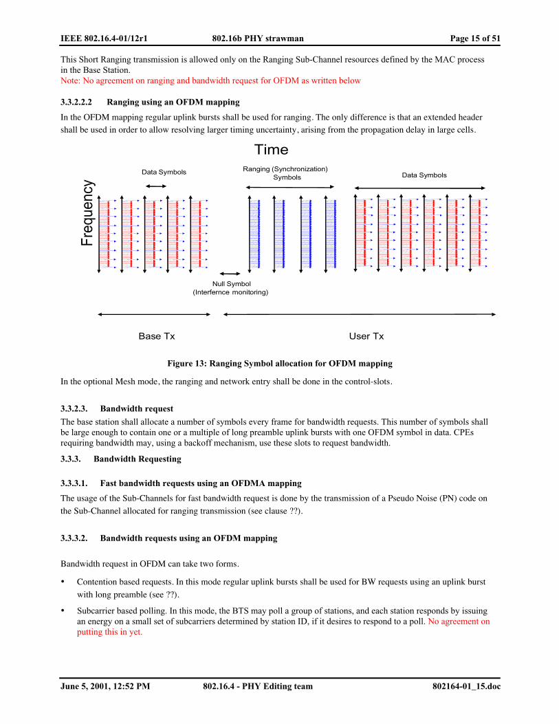
3.3.2.2.2 Ranging using an OFDM mapping
In the OFDM mapping regular uplink bursts shall be used for ranging. The only difference is that an extended headershall be used in order to allow resolving larger timing uncertainty, arising from the propagation delay in large cells.
Freq
uenc
y
Ranging (Synchronization)Symbols
Data Symbols
Time
Null Symbol(Interfernce monitoring)
Base Tx User Tx
Data Symbols
Figure 13: Ranging Symbol allocation for OFDM mapping
In the optional Mesh mode, the ranging and network entry shall be done in the control-slots.
3.3.2.3. Bandwidth request
The base station shall allocate a number of symbols every frame for bandwidth requests. This number of symbols shallbe large enough to contain one or a multiple of long preamble uplink bursts with one OFDM symbol in data. CPEsrequiring bandwidth may, using a backoff mechanism, use these slots to request bandwidth.
3.3.3. Bandwidth Requesting
3.3.3.1. Fast bandwidth requests using an OFDMA mapping
The usage of the Sub-Channels for fast bandwidth request is done by the transmission of a Pseudo Noise (PN) code on
the Sub-Channel allocated for ranging transmission (see clause ??).
3.3.3.2. Bandwidth requests using an OFDM mapping
Bandwidth request in OFDM can take two forms.
• Contention based requests. In this mode regular uplink bursts shall be used for BW requests using an uplink burst
with long preamble (see ??).
• Subcarrier based polling. In this mode, the BTS may poll a group of stations, and each station responds by issuingan energy on a small set of subcarriers determined by station ID, if it desires to respond to a poll. No agreement onputting this in yet.
IEEE 802.16.4-01/12r1 802.16b PHY strawman Page 16 of 51
June 5, 2001, 12:52 PM 802.16.4 - PHY Editing team 802164-01_15.doc
4. Data encoding (Octavian- Brian, Editing Team)
Data encoding is composed of three steps: randomizer, forward error correction (FEC) and interleaving. They shall beapplied in this order at transmission. The complementary operations shall be applied in reverse order at reception.Table 7 describes the mandatory and optional coding schemes:
FEC Interleaving64-FFTOFDMmode
256-FFTOFDMmode
OFDMAOptional
ModeConcatenated RS and CC with zero tailing 802.11a Main Main -Concatenated RS and CC with tail biting 802.11a Optional Optional -Convolutional with zero tailing 802.11a Optional Optional -Convolutional with tail biting 802.11a Optional Optional -Concatenated RS and CC with tail biting PRBS - - MainTurbo Product Codes specific Optional Optional OptionalTurbo Convolutional Codes specific Optional Optional Optional
Table 7: Mandatory and optional coding schemes
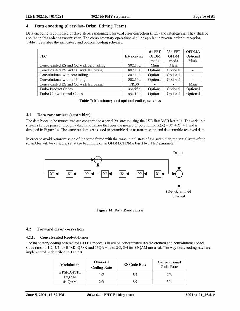
4.1. Data randomizer (scrambler)The data bytes to be transmitted are converted to a serial bit stream using the LSB first MSB last rule. The serial bitstream shall be passed through a data randomizer that uses the generator polynomial R(X) = X7 + X4 + 1 and isdepicted in Figure 14. The same randomizer is used to scramble data at transmission and de-scramble received data.
In order to avoid retransmission of the same frame with the same initial state of the scrambler, the initial state of thescrambler will be variable, set at the beginning of an OFDM/OFDMA burst to a TBD parameter.
X5 X6 X4 X3 X7 X2 X1
Data in
(De-)Scrambled data out
Figure 14: Data Randomizer
4.2. Forward error correction
4.2.1. Concatenated Reed-Solomon
The mandatory coding scheme for all FFT modes is based on concatenated Reed-Solomon and convolutional codes.Code rates of 1/2, 3/4 for BPSK, QPSK and 16QAM, and 2/3, 3/4 for 64QAM are used. The way these coding rates areimplemented is described in Table 8
ModulationOver-All
Coding RateRS Code Rate
ConvolutionalCode Rate
BPSK,QPSK,16QAM
1/2 3/4 2/3
64 QAM 2/3 8/9 3/4

IEEE 802.16.4-01/12r1 802.16b PHY strawman Page 17 of 51
June 5, 2001, 12:52 PM 802.16.4 - PHY Editing team 802164-01_15.doc
BPSK,QPSK,16QAM64 QAM
3/4 9/10 5/6
Table 8: Coding modes
The Reed-Solomon-Convolutional coding rate 1/2 shall be used as the coding mode when requesting access to thenetwork. The serial data from the scrambler is, de-serialized, then passed through the RS encoder, serialized again andthen passed to a convolutional encoder. For 64-FFT and 256-FFT the convolutional encoder shall use zero tailing andfor the optional 2048-FFT OFDMA mode it shall employ tail biting. Optionally, the OFDM mode may also employ tailbiting.
4.2.1.1. Reed Solomon encoding
The Reed Solomon encoding process shall use the systematic RS(255,239,8), with the possibility to make a variableRS(N,K,T), where:
• N - overall bytes, after encoding• K - data bytes before encoding• T - data bytes that can be fixed
The following polynomials are used for the systematic code:
� Code generator polynomial: hexTxxxxxg 02),)...()()(()( 12210 =++++= − λλλλλ
� Field Generator polynomial: 1)( 2348 ++++= xxxxxp
4.2.1.2. Convolutional encoding
Data bits issued from the Reed Solomon encoder, described in clause Figure 15, shall feed the convolutional encoderdepicted in Figure 15.
ConvolutionalEncoder
ConvolutionalEncoder
Puncturingwith
Serial Output
Puncturingwith
Serial Output
Datainput
Dataoutput
X
Y
Figure 15: Convolutional encoder block diagram
The Convolutional encoder shall have a constraint length equal to k=7 and shall use the following mother codes:
octG 1711 = For X
octG 1331 = For Y
A basic convolutional encoding scheme, as depicted in Figure 16, shall be used.

IEEE 802.16.4-01/12r1 802.16b PHY strawman Page 18 of 51
June 5, 2001, 12:52 PM 802.16.4 - PHY Editing team 802164-01_15.doc
Data in
X Output
Y Output
1 BitDelay
bn-2
1 BitDelay
bn-1
1 BitDelay
bn-3
1 BitDelay
bn-2
1 BitDelay
bn-1
1 BitDelay
bn-3
Figure 16: Convolutional encoder basic scheme
The puncturing pattern shall be as defined in Table 9.
CC CodeRate
Puncturing PatternTransmitted Sequence(after parallel to serial conversion)
32 X : 1 0
Y : 1 1 211 YYX
43 X : 1 0 1
Y : 1 1 0 3211 XYYX
65 X : 1 0 1 0 1
Y : 1 1 0 1 0 543211 XYXYYX
Table 9: Puncturing patterns
4.2.1.3. Block Lengths and Concatenated Code Rates
Table XX (reference to the next table) gives the block sizes and the code rates used for the different modulations andcode rates:
ModulationBlock Size
(Bytes)Over-All
Coding RateRS Coding
CCCoding Rate
QPSK 8 ~1/2 (12,8,2) 2/3QPSK 13 ~3/4 (15,13,1) 5/6QPSK 18 1/2 (24,18,3) 2/3QPSK 26 ~3/4 (30,26,2) 5/6
16QAM 36 1/2 (48,36,6) 2/316QAM 54 3/4 (60,54,3) 5/664QAM 72 2/3 (81,72,4) 3/464QAM 82 ~3/4 (90,82,4) 5/6
Table 10: RS and CC coding rates as function of modulation
4.2.2. Optional convolutional encoder
For 64-FFT and 256-FFT an optional convolutional encoder can be used instead of the concatenated RS andconvolutional coding.
IEEE 802.16.4-01/12r1 802.16b PHY strawman Page 19 of 51
June 5, 2001, 12:52 PM 802.16.4 - PHY Editing team 802164-01_15.doc
4.2.2.1. Convolutional encoder
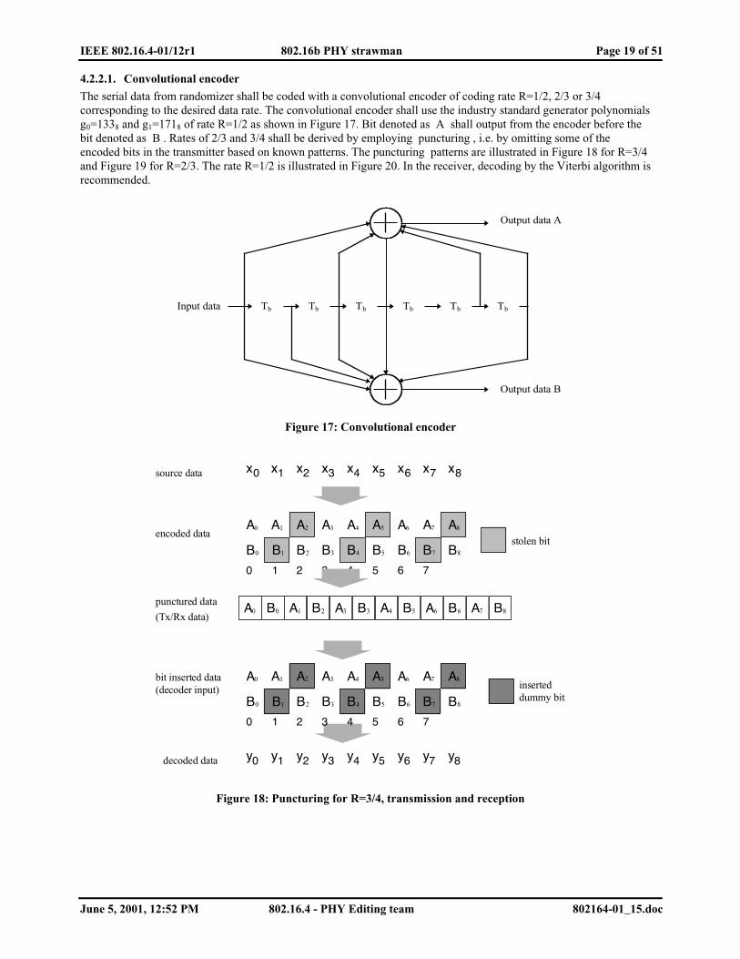
The serial data from randomizer shall be coded with a convolutional encoder of coding rate R=1/2, 2/3 or 3/4corresponding to the desired data rate. The convolutional encoder shall use the industry standard generator polynomialsg0=1338 and g1=1718 of rate R=1/2 as shown in Figure 17. Bit denoted as A shall output from the encoder before thebit denoted as B . Rates of 2/3 and 3/4 shall be derived by employing puncturing , i.e. by omitting some of theencoded bits in the transmitter based on known patterns. The puncturing patterns are illustrated in Figure 18 for R=3/4and Figure 19 for R=2/3. The rate R=1/2 is illustrated in Figure 20. In the receiver, decoding by the Viterbi algorithm isrecommended.
Tb Tb Tb TbTb Input data
Output data A
Output data B
Tb
Figure 17: Convolutional encoder
source data
encoded data
punctured data
(Tx/Rx data)
bit inserted data(decoder input)
decoded data
stolen bit
inserteddummy bit
x0 x1 x2 x3 x4 x5 x6 x7 x8
A0 A1 A2 A3 A4 A5 A6 A7 A8
B0
0
B1
1
B2
2
B3
3
B4
4
B5
5
B6
6
B7
7
B8
y0 y1 y2 y3 y4 y5 y6 y7 y8
A0 B0 A1 B2 A3 B3 A4 B5 A6 B6 A7 B8
A0 A1 A2 A3 A4 A5 A6 A7 A8
B0
0
B1
1
B2
2
B3
3
B4
4
B5
5
B6
6
B7
7
B8
Figure 18: Puncturing for R=3/4, transmission and reception

IEEE 802.16.4-01/12r1 802.16b PHY strawman Page 20 of 51
June 5, 2001, 12:52 PM 802.16.4 - PHY Editing team 802164-01_15.doc
source data
encoded data
punctured data
(Tx/Rx data)
bit inserted data(decoder input)
decoded data
stolen bit
inserteddummy bit
x0 x1 x2 x3 x4 x5
A0 A1 A2 A3 A4 A5
B0
0
B1
1
B2
2
B3
3
B4
4
B5
5
y0 y1 y2 y3 y4 y5
A0 B0 A1 A2 B2 A3 A4 B4 A5
A0 A1 A2 A3 A4 A5
B0
0
B1
1
B2
2
B3
3
B4
4
B5
5
Figure 19: Puncturing for R=2/3, transmission and reception
source data
encoded data
Tx/Rx data
decoder input
decoded data
x0 x1 x2 x3 x4 x5
A0 A1 A2 A3 A4 A5
B0
0
B1
1
B2
2
B3
3
B4
4
B5
5
y0 y1 y2 y3 y4 y5
A0 B0 A1 B1 A2 B2 A3 B3 A4 B4 A5 B5
A0 A1 A2 A3 A4 A5
B0
0
B1
1
B2
2
B3
3
B4
4
B5
5
Figure 20: Bit ordering for R=1/2, transmission and reception

IEEE 802.16.4-01/12r1 802.16b PHY strawman Page 21 of 51
June 5, 2001, 12:52 PM 802.16.4 - PHY Editing team 802164-01_15.doc
4.3. Bit interleaving
4.3.1. Bit interleaving for OFDM modes (64-FFT and 256-FFT)
All encoded data bits shall be interleaved by block interleaver with a block size corresponding to the number of codedbits per OFDM symbol, NCBPS. The interleaver is defined by a two step permutation. The first ensures that adjacentcoded bits are mapped onto nonadjacent sub-carriers. The second permutation insures that adjacent coded bits aremapped alternately onto less or more significant bits of the constellation, thus avoiding long runs of lowly reliable bits(LSB).
Let NBPSC be the number of bits per sub-carrier, i.e. 1, 2, 4 or 6 for BPSK, QPSK, 16QAM ro 64QAM, respectively. Lets = max(NBPSC/2,1). Let k be the index of the coded bit before the first permutation at transmission, m be the index afterthe first and before the second permutation and j be the index after the second permutation, just prior to modulationmapping.
The first permutation is defined by the rule:
m = (NCBPS/16) (k mod 16) + floor(k/16) k = 0, 1, , NCB PS-1
The second permutation is defined by the rule:
j = s * floor(m/s) + (m + NCBPS — floor(16 * m/NCBPS)) mod s m = 0, 1, , NCBPS-1
The deinterleaver, which performs the inverse operation, is also defined by two permutations. Let j be the index of thereceived bit before the first permutation, m be the index after the first and before the second permutation and k be theindex after the second permutation, just prior to delivering the coded bits to the convolutional decoder.
The first permutation is defined by the rule:
m = s * floor(j/s) + (j + floor(16 * j/NCBPS) ) mod s j = 0, 1, , NCBPS-1
The second permutation is defined by the rule:
k = 16 * m — (NCBPS-1) * floor(16 * m/NCBPS) m = 0, 1, , NCBPS-1
The first permutation in the deinterleaver is the inverse of the second permutation in the interleaver, and conversely.
4.3.2. Bit interleaving for optional OFDMA mode
The encoded data encoded is passed through a bit interleaver with a nominal size of 3 Sub-Channel allocation units for2048-FFT mode (OFDMA). The interleaver size depends on the modulation used. Table 11 summarizes the bit-interleaver sizes as a function of the modulation and coding.
Modulation OFMDA(FFT 2048)
BPSK 144QPSK 288
QAM16 576QAM64 864
Table 11: Bit-Interleaver size for optional OFDMA as a function of the Modulation
The interleaver scrambles the order of the input bits to produce the interleaved data, which is then fed to the mapperand the Sub-Channel allocation for OFDMA.
The PRBS generator depicted in Figure 21 is used to achieve the bit interleaver array, it is initialized with the binaryvalue: 0001011010.The PRBS generator produces an index value, which shall correspond to the new position of the input bit into theoutput interleaved data burst.The interleaver shall use the following algorithm:� The Interleaver indexes range from 1 to n (where n denotes the block size to be interleaved)� For each input bit, the PRBS shall be rotated, the rotation produces a number, which is the value of the PRBS
memory register.

IEEE 802.16.4-01/12r1 802.16b PHY strawman Page 22 of 51
June 5, 2001, 12:52 PM 802.16.4 - PHY Editing team 802164-01_15.doc
� If the obtained number is bigger than n, it shall be discarded and the PRBS shall be rotated again. The rotationshall continue until an index between 1 to n is produced.
� The obtained index shall be used to address the position of the processed bit into the output interleaved data burst
10987654321
0101101000InitalizationSequence
MSB LSB
Figure 21: PRBS for Bit-Interleaver array
4.4. Optional FEC and interleaving - Block Turbo Coding
4.4.1. Proposed Block Turbo Codes
This type of coding based on the product of two or more simple component codes, is also called Turbo Product code,TPC. The decoding is based on the concept of Soft-in/Soft-out (SISO) iterative decoding (i.e, Turbo decoding ). Thecomponent codes recommended for this proposal are binary extended Hamming codes or Parity check codes. Theschemes supported follow the recommendation of the IEEE802.16.1 mode B. However, more flexibility in block sizeand code rates is enabled. The main benefits of using TPC mode are typically 2dB better performance over theConcatenated RS, and shorter decoding delays. A detailed description of Turbo Product Codes is included as Section4.4.2. In this Section we present some particular turbo product codes that are perfectly matched for the proposedframing/modulation structure.
4.4.1.1. Block Turbo Constituent Codes
As mentioned in Section 4.4.2, TPCs are constructed as a product of simple component codes. The completeconstituent code set is defined in Table 12.
(64, 57) Extended Hamming Code(32,26) Extended Hamming Code(16,11) Extended Hamming Code(32,31) Parity Check Code(16,15) Parity Check Code(4,3) Parity Check Code
Table 12: Constituent Block Turbo Code List
4.4.1.2. Overall Turbo Product Codes
The defined Turbo Product Codes are all multiples of 48 bits to facilitate integration into the framing structure. Table13 lists the possible codes, rates and block size in bits. The block sizes are achieved by bit shortening as described inSection 4.4.2.
X-Code Y-Code Z-Code Rate Block Size

IEEE 802.16.4-01/12r1 802.16b PHY strawman Page 23 of 51
June 5, 2001, 12:52 PM 802.16.4 - PHY Editing team 802164-01_15.doc
56,49 55,48 0.76 307225,19 25,19 5,4 0.46 307248,41 48,41 0.72 230424,18 24,18 4,3 0.42 230464,57 21,20 0.85 129641,34 32,26 0.67 129664,57 12,11 0.82 76828,22 28,22 0.62 76854,47 9,8 0.77 48030,24 16,11 0.55 48032,26 6,5 0.68 19214,9 14,9 0.41 192
Table 13: TPC Example Codes
The codes may be shortened using the method described in Section 4.4.2. Shortening should only be performed inmultiples of 48 bits.
When using Turbo Product Codes additional Bit Interleaver sizes are defined as in Table 14.
X-Code Y-Code Z-CodeBit Interleaver
allocation56,49 55,48 102425,19 25,19 5,4 102448,41 48,41 76824,18 24,18 4,3 76864,57 21,20 64841,34 32,26 64864,57 12,11 76828,22 28,22 76854,47 9,8 48030,24 16,11 48032,26 6,5 19214,9 14,9 192
Table 14: Optimal Bit Interleaver Sizes
Termination of allocations does not have to be the multiplications of the above bit interleaver sizes. Sizes in anymultiple of 48, up to a multiple of 12 can be used to terminate the allocation.
4.4.2. Turbo Code Description
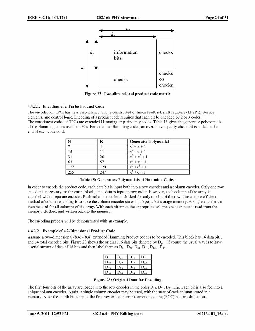
The Block Turbo Code is a Turbo decoded Product Code (TPC). The idea of this coding scheme is to use well-knownproduct codes in a matrix form for two-dimensional coding, or in a cubical form for three dimensions.The matrix form of the two-dimensional code is depicted in Figure 22. The kx information bits in the rows are encodedinto nx bits, by using a binary block (nx, kx) code. The binary block codes employed are based on extended Hammingcodes.
The redundancy of the code is rx = nx - kx and dx is the Hamming distance. After encoding the rows, the columns areencoded using another block code (ny, ky), where the check bits of the first code are also encoded. The overall blocksize of such a product code is n = nx×ny, the total number of information bits k = kx « ky and the code rate is R = Rx×Ry,where Ri = ki/ni, i=x, y. The Hamming distance of the product code is d = dx×dy.
IEEE 802.16.4-01/12r1 802.16b PHY strawman Page 24 of 51
June 5, 2001, 12:52 PM 802.16.4 - PHY Editing team 802164-01_15.doc
checksonchecks
checks
checksky
ny
nx
kx
informationbits
Figure 22: Two-dimensional product code matrix
4.4.2.1. Encoding of a Turbo Product Code
The encoder for TPCs has near zero latency, and is constructed of linear feedback shift registers (LFSRs), storageelements, and control logic. Encoding of a product code requires that each bit be encoded by 2 or 3 codes.The constituent codes of TPCs are extended Hamming or parity only codes. Table 15 gives the generator polynomialsof the Hamming codes used in TPCs. For extended Hamming codes, an overall even parity check bit is added at theend of each codeword.
N K Generator Polynomial7 4 x3 + x + 115 11 x4 + x + 131 26 x5 + x2 + 163 57 x6 + x + 1127 120 x7 +x3 + 1255 247 x8 +x + 1
Table 15: Generators Polynomials of Hamming Codes:
In order to encode the product code, each data bit is input both into a row encoder and a column encoder. Only one rowencoder is necessary for the entire block, since data is input in row order. However, each column of the array isencoded with a separate encoder. Each column encoder is clocked for only one bit of the row, thus a more efficientmethod of column encoding is to store the column encoder states in a kx×(ny-ky) storage memory. A single encoder canthen be used for all columns of the array. With each bit input, the appropriate column encoder state is read from thememory, clocked, and written back to the memory.
The encoding process will be demonstrated with an example.
4.4.2.2. Example of a 2-Dimesional Product Code
Assume a two-dimensional (8,4)×(8,4) extended Hamming Product code is to be encoded. This block has 16 data bits,and 64 total encoded bits. Figure 23 shows the original 16 data bits denoted by Dyx. Of course the usual way is to havea serial stream of data of 16 bits and then label them as D11, D21, D31, D41, D12, , D44.
D11 D21 D31 D41
D12 D22 D32 D42
D13 D23 D33 D43
D14 D24 D34 D44
Figure 23: Original Data for Encoding
The first four bits of the array are loaded into the row encoder in the order D11, D21, D31, D41. Each bit is also fed into aunique column encoder. Again, a single column encoder may be used, with the state of each column stored in amemory. After the fourth bit is input, the first row encoder error correction coding (ECC) bits are shifted out.
IEEE 802.16.4-01/12r1 802.16b PHY strawman Page 25 of 51
June 5, 2001, 12:52 PM 802.16.4 - PHY Editing team 802164-01_15.doc
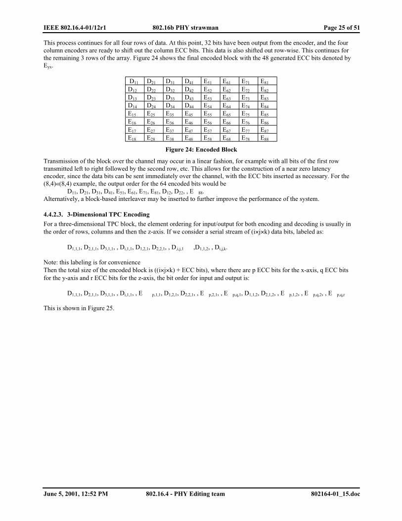
This process continues for all four rows of data. At this point, 32 bits have been output from the encoder, and the fourcolumn encoders are ready to shift out the column ECC bits. This data is also shifted out row-wise. This continues forthe remaining 3 rows of the array. Figure 24 shows the final encoded block with the 48 generated ECC bits denoted byEyx.
D11 D21 D31 D41 E51 E61 E71 E81
D12 D22 D32 D42 E52 E62 E72 E82
D13 D23 D33 D43 E53 E63 E73 E83
D14 D24 D34 D44 E54 E64 E74 E84
E15 E25 E35 E45 E55 E65 E75 E85
E16 E26 E36 E46 E56 E66 E76 E86
E17 E27 E37 E47 E57 E67 E77 E87
E18 E28 E38 E48 E58 E68 E78 E88
Figure 24: Encoded Block
Transmission of the block over the channel may occur in a linear fashion, for example with all bits of the first rowtransmitted left to right followed by the second row, etc. This allows for the construction of a near zero latencyencoder, since the data bits can be sent immediately over the channel, with the ECC bits inserted as necessary. For the(8,4)«(8,4) example, the output order for the 64 encoded bits would be
D11, D21, D31, D41, E51, E61, E71, E81, D12, D22, , E 88.Alternatively, a block-based interleaver may be inserted to further improve the performance of the system.
4.4.2.3. 3-Dimensional TPC Encoding
For a three-dimensional TPC block, the element ordering for input/output for both encoding and decoding is usually inthe order of rows, columns and then the z-axis. If we consider a serial stream of (i×j×k) data bits, labeled as:
D1,1,1, D2,1,1, D3,1,1, , Di,1,1, D1,2,1, D2,2,1, , D,i,j,1 ,D1,1,2, , Di,j,k.
Note: this labeling is for convenienceThen the total size of the encoded block is ((i×j×k) + ECC bits), where there are p ECC bits for the x-axis, q ECC bitsfor the y-axis and r ECC bits for the z-axis, the bit order for input and output is:
D1,1,1, D2,1,1, D3,1,1, , Di,1,1, , E p,1,1, D1,2,1, D2,2,1, , E p,2,1, , E p,q,1, D1,1,2, D2,1,2, , E p,1,2, , E p,q,2, , E p,q,r
This is shown in Figure 25.

IEEE 802.16.4-01/12r1 802.16b PHY strawman Page 26 of 51
June 5, 2001, 12:52 PM 802.16.4 - PHY Editing team 802164-01_15.doc
D1,1,1 D2,1,1
D1,2,1 D2,2,1
D1,j,1 D2,j,1
Di,1,1
Di,2,1
Di,j,1
E1,j+1,1 E2,j+1,1
E1,q,1 E2,q,1
Ei,j+1,1
Ei,q,1
Ei+1,1,1
Ei+1,2,1
Ep,1,1
Ep,2,1
Ei+1,j,1 Ep,j,1
Ei+1,j+1,1 Ep,j+1,1
Ei+1,q,1 Ep,q,1
Ep,1,2
Ep,1,r
Ep,j,2
Ep,j,r
Ep,j+1,2
Ep,j+1,r
Ep,q,2
Ep,q,r
y z
x
Figure 25: Structure of 3-Dimensional TPC
Notation:• the codes defined for the rows (x-axis) are binary (nx,kx) block codes• the codes defined for the columns (y-axis) are binary (ny,ky) block codes• the codes defined for the z-dimension (z-axis) are binary (nz,kz) block codes• data bits are noted Dy,x,z and parity bits are noted Ey,x,z
4.4.2.4. Shortened TPCs
To match packet sizes, a product code may be shortened by removing symbols from the array. In the two-dimensionalcase rows, columns or parts thereof can be removed until the appropriate size is reached. Unlike one-dimensional codes(such as Reed-Solomon codes), parity bits are removed as part of shortening process, helping to keep the code ratehigh.
There are two steps in the process of shortening of product codes. The first is to remove an entire row or column from a2-dimensional code, or an entire X, Y, or Z plane from a 3-dimensional code. This is equivalent to shortening theconstituent codes that make up the product code. This method enables a coarse granularity on shortening, and at thesame time maintaining the highest code rate possible by removing both data and parity symbols. Further shortening isobtained by removing individual bits from the first row of a 2-dimensional code, or from the top plane of a 3-dimensional code.
4.4.2.5. Example of a Shortened 2-Dimensional TPC
For example, assume a 456-bit block size is required with a code rate of approximately 0.6. The base code chosenbefore shortening is the (32,26)×(32,26) code which has a data size of 676 bits. Shortening all rows by 5 bits and allcolumns by 4 bits results in a (27,21)×(28,22) code, with a data size of 462 bits. To get the exact block size, the firstrow of the product is shortened by an additional 6 bits. The final code is a (750,456) code, with a code rate of 0.608.Figure 26 shows the structure of the resultant block.

IEEE 802.16.4-01/12r1 802.16b PHY strawman Page 27 of 51
June 5, 2001, 12:52 PM 802.16.4 - PHY Editing team 802164-01_15.doc
27 bits
28 bits
Shorten 6Additional Bits
DataBits
ECC Bits
UnshortenedBlock
26 bits 6 bits
26 bits
6 bits
x
y
Zero bits
Figure 26: Structure of Shortened 2 D Block
Modifications to the encoder to support shortening are minimal. The shortening procedure is trivial, and yet anextremely powerful tool that enables construction of a very versatile code set.
4.4.2.6. Example of a Shortened 3-Dimensional TPC
Suppose a 0.4 - 0.45 rate code is required with a data block size of 1096 bits. The following shows one possible methodto create this code.
Start with a (32,26)×(32,26)×(4,3) code. The optimum shortening for this code is to remove rows and columns, whileleaving the already very short z-axis alone. Therefore, since a 1096 bit 3-Dimensional code is required, the desiredvector data size can be found by taking the square root of 1096/3 and rounding up. This yields a row/column size ofabout 20. In fact, having a row size of 20, a column size of 19, and a z-column size of 3 gives the closest block size to1096 bits.
The code size is now a (26,20)×(25,19)×(4,3) = (2600,1140). To get the exact data size, we further shorten the firstplane of the code by 44 bits. This is accomplished by shortening 2 full rows from the first (xy)-plane, with each rowremoving 20 bits from the data block, and shortening another 4 bits from the next row. This results in a (2544,1096)code, with rate = 0.43. The following diagram shows the original code, along with the physical location of theshortened bits.Figure 27 shows the original code along with the physical location of the shortened bits.

IEEE 802.16.4-01/12r1 802.16b PHY strawman Page 28 of 51
June 5, 2001, 12:52 PM 802.16.4 - PHY Editing team 802164-01_15.doc
Data Bits
26
6
26 6
Shortenby 6
26
Shortenby 7
25
ECC Bits
Shorten frontplane by
2 rows and 4 bits
OriginalUnshortened
Block
FinalShortened
Block
3
1
x
yz
Figure 27: Structure of Shortened 3-D Block
4.4.2.7. Iterative Decoding
Huge performance advantages may be directly associated with the decoding mechanism for product codes. There aremany different ways to decode product codes and each has its merits, however, the goal is maximum performance for amanageable level of complexity.
It is known that if it is possible to use unquantised information (so called soft information) from the demodulator todecode an error correcting code, then an additional gain of up to 2 dB over fully quantised (hard decision) informationis achievable. It is therefore desirable to have soft information decision available to the TPC decoder.
Of course, we could in theory consider the decoding of this code a single linear code of size (nx×ny×nz, kx×ky×kz), usinga soft decision decoder, but this will in general (apart from the smallest, and of course worst performing) beprohibitively complex.
It makes sense therefore, since these codes are constructed from (simple) constituent code that these soft decoders areused to decode the overall code. However until recently there have only been hard decision decoders for theseconstituent decoders. In recent years the computational power of devices has made it possible to consider (sub optimal)soft decision decoders for all linear codes. This is only half the solution as the main difficulty is with passing theinformation from one decoder to the next (i.e. when switching from decoding the rows to decoding the columns). Forthis, accuracy will need to be kept to a maximum, and so using soft input soft output (SISO) decoders will need to beconsidered. This is such that an estimate of the transmitted code word may be found and also an indication of thereliability. This new estimate may then be passed onto the next decoding cycle. Inevitably, there will be somedegradation from optimal if we are to achieve our decoding using this method, but it does enable the complexity to bereduced to a level that can be implemented. Also, studies have shown that this degradation is very small, so thisdecoding system is very powerful.
What follows now is an explanation regarding the iterative nature of the decoding procedure. If we consider that, given2-D TPC block, we define the first round of row and column decoding as a single iteration. We may then performfurther iterations, if required. Thus, the main areas of investigation are that of the SISOs, and that of using somepreviously decoded information in subsequent decoding operations. These are both separate and yet connected areas ofinterest, as shall be explained.
With regards to the SISOs, there are many different methods including the following which have been described indetail in published academic papers:
1) Soft-Output Viterbi Algorithm (SOVA) [1]2) The modified Chase algorithm [2]3) The BCJR algorithm [3],
IEEE 802.16.4-01/12r1 802.16b PHY strawman Page 29 of 51
June 5, 2001, 12:52 PM 802.16.4 - PHY Editing team 802164-01_15.doc
There have been many other papers explaining these algorithms both as independent algorithms for coding schemesand as part of turbo type decoding schemes. It must be noted that these are not the only algorithms that can achieve softinput soft output style decoding, but they are at present the most readily cited in academic literature.Each block in a product code is decoded using the information from a previous block decoding. This is then repeated asmany times as. In this way, each decoding iteration builds on the previous decoding performance.
Figure 28 illustrates the decoding of a 2-D TPC. Note here that prior to each decoding there needs to be a mathematicaloperation on all the data we have at that particular time, that is the current estimate of the decoded bits, the originalestimate from the demodulator (this will not be used in the first decoding) and the channel information (whereapplicable).
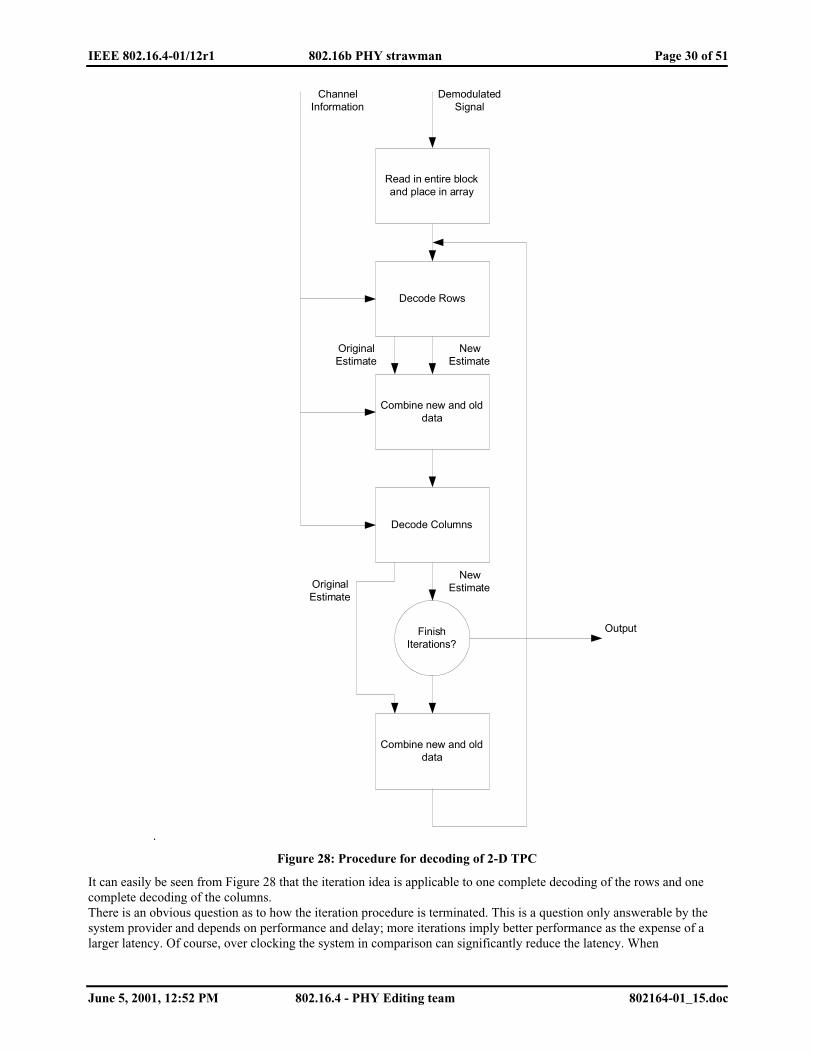
IEEE 802.16.4-01/12r1 802.16b PHY strawman Page 30 of 51
June 5, 2001, 12:52 PM 802.16.4 - PHY Editing team 802164-01_15.doc
.
Read in entire blockand place in array
Decode Rows
Combine new and olddata
Decode Columns
Combine new and olddata
FinishIterations?
Output
DemodulatedSignal
ChannelInformation
OriginalEstimate
OriginalEstimate
NewEstimate
NewEstimate
Figure 28: Procedure for decoding of 2-D TPC
It can easily be seen from Figure 28 that the iteration idea is applicable to one complete decoding of the rows and onecomplete decoding of the columns.There is an obvious question as to how the iteration procedure is terminated. This is a question only answerable by thesystem provider and depends on performance and delay; more iterations imply better performance as the expense of alarger latency. Of course, over clocking the system in comparison can significantly reduce the latency. When

IEEE 802.16.4-01/12r1 802.16b PHY strawman Page 31 of 51
June 5, 2001, 12:52 PM 802.16.4 - PHY Editing team 802164-01_15.doc
considering hardware, the problem of varying delays may be encountered, thus it may be advantageous to fix thenumber of iterations performed.
4.4.3. Referecences
[1] G.Drury, G.Markarian, K.Pickavance. Coding and Modulation for Digital Television , KLUWER AcademicPublishers, USA, 2001
[2] ETSI EN 301 021[3] L.Bahl, J.Jelinek, J.Raviv, and F.Raviv, "Optimal Decoding of Linear Codes for minimising symbol error rate",
IEEE Transactions on Information Theory, vol. IT-20, pp.284-287, March 1974.
4.5. Optional FEC and interleaving - Convolutional Turbo CodesAn optional convolutional turbo code may be employed to maximize range and throughput performance. The TurboCode is based on Recursive Systematic Convolutional (RSC) code with a base rate of 1/2. The frames are encoded inblocks of N information bits (FRAME SIZE) listed in greater detail below. Figure 29 illustrates the overall encodingprocess and Figure 30 shows the RSC encoder.
P1 & P2
SYS
Permutation
RSC
PUNCTURE
C O D E W O R D
Interleave
Figure 29: Turbo Encoder
D INPUT
OUTPUT
D D D
Figure 30: RSC Encoder
4.5.1. Termination
Each constituent code shall be terminated using a tail biting scheme.
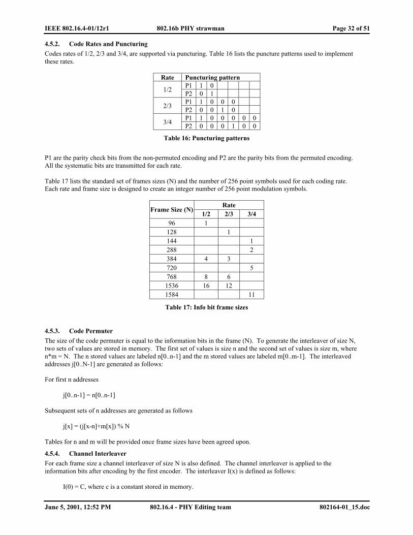
IEEE 802.16.4-01/12r1 802.16b PHY strawman Page 32 of 51
June 5, 2001, 12:52 PM 802.16.4 - PHY Editing team 802164-01_15.doc
4.5.2. Code Rates and Puncturing
Codes rates of 1/2, 2/3 and 3/4, are supported via puncturing. Table 16 lists the puncture patterns used to implementthese rates.
Rate Puncturing patternP1 1 0
1/2P2 0 1P1 1 0 0 0
2/3P2 0 0 1 0P1 1 0 0 0 0 0
3/4P2 0 0 0 1 0 0
Table 16: Puncturing patterns
P1 are the parity check bits from the non-permuted encoding and P2 are the parity bits from the permuted encoding.All the systematic bits are transmitted for each rate.
Table 17 lists the standard set of frames sizes (N) and the number of 256 point symbols used for each coding rate.Each rate and frame size is designed to create an integer number of 256 point modulation symbols.
RateFrame Size (N)
1/2 2/3 3/496 1
128 1144 1288 2384 4 3720 5768 8 61536 16 121584 11
Table 17: Info bit frame sizes
4.5.3. Code Permuter
The size of the code permuter is equal to the information bits in the frame (N). To generate the interleaver of size N,two sets of values are stored in memory. The first set of values is size n and the second set of values is size m, wheren*m = N. The n stored values are labeled n[0..n-1] and the m stored values are labeled m[0..m-1]. The interleavedaddresses j[0..N-1] are generated as follows:
For first n addresses
j[0..n-1] = n[0..n-1]
Subsequent sets of n addresses are generated as follows
j[x] = (j[x-n]+m[x]) % N
Tables for n and m will be provided once frame sizes have been agreed upon.
4.5.4. Channel Interleaver
For each frame size a channel interleaver of size N is also defined. The channel interleaver is applied to theinformation bits after encoding by the first encoder. The interleaver I(x) is defined as follows:
I(0) = C, where c is a constant stored in memory.

IEEE 802.16.4-01/12r1 802.16b PHY strawman Page 33 of 51
June 5, 2001, 12:52 PM 802.16.4 - PHY Editing team 802164-01_15.doc
I(x) = [I(x-1) + p] % N, where p is relatively prime to N.
4.5.5. CRC
A CRC-16 check sum block shall be added to each frame and is included in the information bits. The polynomial is x16
+ x15 + x2 + 1.
5. Constellation Mapping (Yossi — Editing Team)
The modulation used both for the UL and DL data carrier is BPSK, QPSK, 16QAM and 64QAM. These modulations
are used adaptively in the downlink and the uplink in order to achieve the maximum throughput for each link.
The modulation on the DL can be changed for each allocation, to best fit the modulation for a specific user/users. When
using OFDMA the power of the modulated carrier can also vary by attenuation or busting of 6dB, this is used for theForward APC.
For the up link each user is allocated a modulation scheme, which is best suited for his needs.
The pilot carriers for the UL and DL are mapped using a BPSK modulation.
5.1. Data Modulation
The data bits entering the mapper are after bit interleaving and they enter serially to the mapper, the mapping
constellations are presented here after in Figure 31:
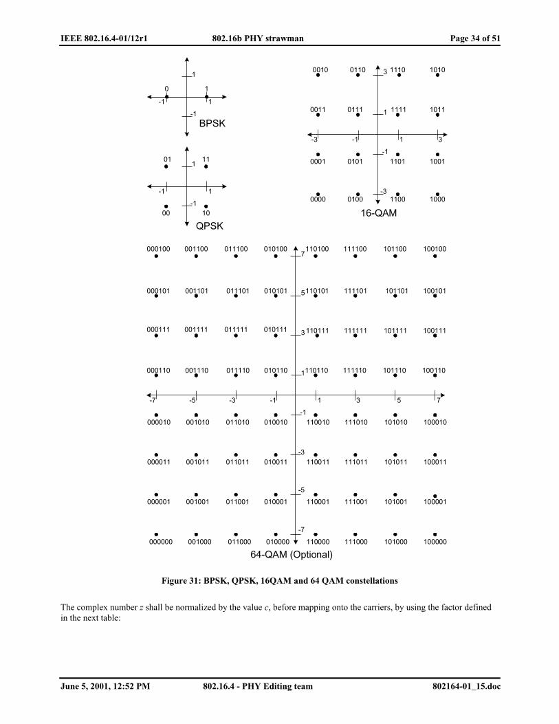
IEEE 802.16.4-01/12r1 802.16b PHY strawman Page 34 of 51
June 5, 2001, 12:52 PM 802.16.4 - PHY Editing team 802164-01_15.doc
1
1
-1
-1
10
1
1
-1
-1
01 11
00 10
1
1
-1
-1
0111
0101 1101
-3
3
-3 3
1111
1010111001100010
0011 1011
1001
1000110001000000
0001
1
1
-1
-1
-3
3
-3 3
5
-5
5
7
7
-7
-7 -5
000100 110100010100011100001100
100101
100100101100111100
101101111101110101
100111101111110111 111111
010101011101001101000101
000111 010111011111001111
010110011110001110000110
000010 010010011010001010
000011 010011011011001011
000001 010001011001001001
000000 010000011000001000
100110101110110110 111110
100010101010110010 111010
100011101011110011 111011
100001101001110001 111001
100000101000110000 111000
BPSK
QPSK16-QAM
64-QAM (Optional)
Figure 31: BPSK, QPSK, 16QAM and 64 QAM constellations
The complex number z shall be normalized by the value c, before mapping onto the carriers, by using the factor definedin the next table:
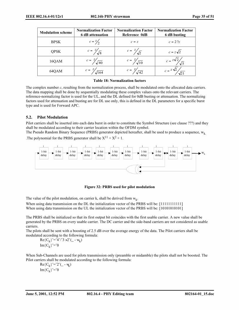
IEEE 802.16.4-01/12r1 802.16b PHY strawman Page 35 of 51
June 5, 2001, 12:52 PM 802.16.4 - PHY Editing team 802164-01_15.doc
Modulation schemeNormalization Factor
6 dB attenuationNormalization Factor
Reference 0dBNormalization Factor
6 dB busting
BPSK 2zc = zc = zc ?= 2
QPSK 8zc =
2zc = 2zc =
16QAM 40zc =
10zc =
52zc =
64QAM 164zc =
42zc =
212zc =
Table 18: Normalization factors
The complex number c, resulting from the normalization process, shall be modulated onto the allocated data carriers.The data mapping shall be done by sequentially modulating these complex values onto the relevant carriers. Thereference-normalizing factor is used for the UL, and the DL defined for 0dB busting or attenuation. The normalizingfactors used for attenuation and busting are for DL use only, this is defined in the DL parameters for a specific bursttype and is used for Forward APC.
5.2. Pilot ModulationPilot carriers shall be inserted into each data burst in order to constitute the Symbol Structure (see clause ???) and theyshall be modulated according to their carrier location within the OFDM symbol.The Pseudo Random Binary Sequence (PRBS) generator depicted hereafter, shall be used to produce a sequence, wk.
.The polynomial for the PRBS generator shall be X11 + X2 + 1.
11111111111
1-bitdelay
1-bitdelay
1-bitdelay
1-bitdelay
1-bitdelay
1-bitdelay
1-bitdelay
1-bitdelay
1-bitdelay
1-bitdelay
1-bitdelay
wk
Figure 32: PRBS used for pilot modulation
The value of the pilot modulation, on carrier k, shall be derived from wk.
When using data transmission on the DL the initialization vector of the PRBS will be: [11111111111]When using data transmission on the UL the initialization vector of the PRBS will be: [10101010101]
The PRBS shall be initialized so that its first output bit coincides with the first usable carrier. A new value shall begenerated by the PRBS on every usable carrier. The DC carrier and the side-band carriers are not considered as usablecarriers.The pilots shall be sent with a boosting of 2.5 dB over the average energy of the data. The Pilot carriers shall bemodulated according to the following formula:
Re{Ck}˚=˚4˚/˚3 × 2˚(_ - wk)
Im{Ck}˚=˚0
When Sub-Channels are used for pilots transmission only (preamble or midamble) the pilots shall not be boosted. ThePilot carriers shall be modulated according to the following formula:
Re{Ck}˚=˚2˚(_ - wk)
Im{Ck}˚=˚0
IEEE 802.16.4-01/12r1 802.16b PHY strawman Page 36 of 51
June 5, 2001, 12:52 PM 802.16.4 - PHY Editing team 802164-01_15.doc
5.3. Ranging Pilot ModulationWhen using the ranging Sub-Channels the user shell modulate the pilots according to the following formula:
Re{Ck}˚=˚˚(_ - wk) / 6
Im{Ck}˚=˚0
Ck is derived in clause XXX
6. RF Characteristics (Drayt, — Nico, Editing Team)
6.1. Regulatory Requirements
6.1.1. Introduction
The 802.16.4 PHY shall operate in the 5 GHz band as allocated by a regulatory body in its operational region.Spectrum allocation in the 5 GHz band is subject to authorities responsible for geographic specific regulatory domainse.g. global, regional, and national. The particular channelization to be used for this standard is dependent on suchallocation as well as the associated regulations for use of the allocations. These regulations are subject to revision, ormay be superseded. In the USA, the FCC is the agency responsible for the allocation of the 5 GHz U-NII bands.
In some regulatory domains several frequency bands may be available for 802.16.4 PHY based FWA devices. Thesebands may be contiguous or not, and different regulatory limits may be applicable. A compliant PHY shall support atleast one frequency band in at least one regulatory domain. The support of specific regulatory domains and of bandswithin the domains shall be indicated by PLME attributes RegDomainsSupported and FrequencyBandsSupported.
6.1.2. FCC Regulatory issues
Equipment based on the 802.16.4 PHY is currently regulated in the USA by FCC document Title 47, Part 15. Aninterpretation of Subpart E, Section 15.407 is provided below for convenience. No rights may be derived from this text,and accuracy is not guaranteed.
The 5.15-5.25GHz lower U-NII band is restricted to indoor use only. As at least one device on an FWA link needs tobe outdoors (typically the base station), this band is not available for FWA. As a result of this, the rule that the devicemust meet the maximum -27 dBm/MHz limit below 5250 MHz and above 5350 MHz applies. For the upper U-NII, thelimits are maximum -27 dBm/MHz below 5715 MHz and above 5835 MHz, and maximum -17 dBm/MHz in the band5715 - 5725 MHz and 5825 - 5835 MHz.
In the middle U-NII band, the transmit power is limited to the lesser of 24 dBm (250 mW) or 11+10log(B26dB) dBm,with the peak power density (n.b. this is not the peak power) not exceeding 11 dBm/MHz. In the upper U-NII band,the transmit power is limited to the lesser of 30 dBm (1W) or 17+10log(B26dB) dBm, with the peak power density notexceeding 17 dBm/MHz. For any multi-point system using directional antenna with gain over 6 dBi, limits for bothbands are reduced by the antenna gain in excess of 6dBi.
6.1.3. ETSI Regulatory issues
Equipment based on the 802.16.4 PHY is currently regulated in Europe by ETSI document TBD. An interpretation ofTBD is provided below for convenience. No rights may be derived from this text, and accuracy is not guaranteed.
6.2. Channelization
6.2.1. Channel Numbering
Channel center frequencies are defined at every integral multiple of 5 MHz above 5 GHz. The relationship betweencenter frequency and channel number is given by the following equation:Channel center frequency = 5000 + 2.5 * nch (MHz)where nch = 0,1, 400. This definition provides a 9-bit unique numbering system of all channels with 2.5 MHz spacingfrom 5 GHz to 6 GHz to provide flexibility to define channelization sets for all current and future regulatory domains.

IEEE 802.16.4-01/12r1 802.16b PHY strawman Page 37 of 51
June 5, 2001, 12:52 PM 802.16.4 - PHY Editing team 802164-01_15.doc
6.2.2. Valid operating channels
The set of valid operating channel numbers by regulatory domain is defined in Table 19. The channels in parenthesisare optional, the others are mandatory.
Channelization (MHz)Regulatorydomain Band (GHz)
20 10 5
USAU-NII-middle
5.25-5.35
(104), 112,120, 128(136)
(102), 106, 110, 114,118, 122, 126, 130,134, (138)
(103), (105), (107), (109), (111), (113),(115), (117), (119), (121), (123), (125),(127), (129), (131), (133), (135), (137)
USAU-NII-upper5.725-5.825
298, 306,314, 322
(292), 296, 300, 304,308, 312, 316, 320,324, (328)
(293), (295), (297), (299), (301), (303),(305), (307), (309), (311), (313), (315),(317), (319), (321), (323), (325), (327)
Table 19: USA U-NII Operating channels
Figure 33 shows the channelization scheme for this standard, which shall be used with the FCC U-NII frequencyallocation. The middle U-NII sub-band accommodates 3 channels of 20MHz, while the upper U-NII band supports 4channels. Both U-NII bands accommodate 8 channels of 10 MHz. Additionally, two optional 20 MHz channels aredefined in the middle U-NII band and one 10 MHz channel in each of the bands. The 5 MHz channelization, which isoptional, provides 18 channels in each band.
5725 5745 5765 5785 5805 5825
5725 5745 5765 5785 5805 5825
5725 5745 5765 5785 5805 5825
5250 5270 5290 5310 5330 5350
5250 5270 5290 5310 5330 5350
5250 5270 5290 5310 5330 5350
Figure 33: USA: U-NII frequency plan
.
6.3. Transmitter Requirements
6.3.1. Transmit Spectrum Mask
The transmitted spectral density of the transmitted signal shall fall within the spectral mask as shown in Figure 34 andTable 20. The measurements shall be made using 100 kHz resolution bandwidth and a 30 kHz video bandwidth.

IEEE 802.16.4-01/12r1 802.16b PHY strawman Page 38 of 51
June 5, 2001, 12:52 PM 802.16.4 - PHY Editing team 802164-01_15.doc
B A DC
-27
0
-32
-50
dBr
f0MHz
Figure 34: Transmit Spectral Mask (see Table 20)
Channelization (MHz) A B C D20 9.5 10.5 19.5 29.510 4.25 TBD TBD TBD5 2.25 TBD TBD TBD
Table 20: Transmit Spectral Mask Parameters
6.3.2. Transmit power levels
The maximum allowable output power according to FCC regulation is shown in Table 21.
Maximum Output PowerRegulatory Domain Band
20 MHz 10 MHz 5 MHzComments
USA U-NII middle 23 dBm 20 dBm 17 dBm Up to 6 dBi antenna gainUSA U-NII upper 29 dBm 26 dBm 23 dBm Up to 6 dBi antenna gain
Table 21: Maximum output power
6.3.3. Transmit Power Level Control
The transmitter shall support monotonic power level control of 45dB minimum with resolution of 3dB.
6.3.4. Transmitter Linearity
Review alternate approaches and how transmitter quality handled in 802.11a/b and similar standards. One suggestedoption is:The transmitter linearity shall be sufficient to ensure minimal distortion of the transmitted OFDM signal. The testmethod will use a notch test method with the assistance of a test mode to create a notched OFDM signal. The averagedepth of the notch shall be TBD dB measured at the transmitter output. Use of an EVM may be used as an alternatetest method, but all equipment must support all defined test modes.
6.3.5. Transmitter Spectral Flatness
The average energy of the constellations in each of the n spectral lines shall deviate no more than the following:
Spectral Lines Spectral Flatness

IEEE 802.16.4-01/12r1 802.16b PHY strawman Page 39 of 51
June 5, 2001, 12:52 PM 802.16.4 - PHY Editing team 802164-01_15.doc
Spectral lines from —n/2 to —1 and +1 to n/2: +/-2dB from their average energy
Spectral lines from —n to —n/2 and +n/2 to n: +2/-4dB from their average energy
Table 22: Maximum output power
This data will be taken from the channel estimation step.
6.3.6. Transmitter Constellation Error and Test Method
This requirement specifies limits for Error Vector Magnitude (EVM) measurements for the constellation elements.
The definition and test method are specified in 802.11a section 17.3.9.6.3. If this test is desired for 802.16.4, thedefinition can be copied straight from the 802.11a spec with the following addition:For OFDMA modes, measurements will be taken with all subchannels active.To separate EVM measurements for the BS and SS.
6.4. Receiver Requirements
6.4.1. Receiver Sensitivity
The packet error rate (PER) shall be less than TBD (%) at the power levels shown below for a standard message andtest conditions. The measurement shall be taken at the antenna port or through a calibrated radiated test environment.
Channel Bandwidth(MHz)
Data Rate(Mbits/s)
Minimum Sensitivity(dBm)
20MHz TBD TBD20MHz TBD TBD20MHz TBD TBD10MHz TBD TBD10MHz TBD TBD10MHz TBD TBD5MHz TBD TBD5MHz TBD TBD5MHz TBD TBD
Table 23: Receiver Sensitivity
Standard test message: TBD bytes of TBD format (possibly 2 std messages —short and long)Test Conditions: room temp, no interference, conducted measurement if RF port available, radiated measurement in acalibrated test environment if antenna is integrated, FEC enabled
6.4.2. Receiver Adjacent and Alternate Channel Rejection
The adjacent channel rejection and alternate channel rejection shall be measured by setting the desired signal s strength3dB above the rate dependent receiver sensitivity and raising the power level of the interfering signal until the specifiederror rate is obtained. The power difference between the interfering signal and the desired channel is the thecorresponding adjacent channel rejection. The interfering signal in the adjacent channel shall be a conformant OFDMsignal, unsynchronized with the signal in the channel under test. For alternate channel testing the test method isidentical except the interfering channel will be any channel other than the adjacent channel.
For the PHY to be compliant, the minimum rejection shall exceed the following:
ChannelBandwidth
Adjacent ChannelRejection
Non-Adjacent channelRejection
IEEE 802.16.4-01/12r1 802.16b PHY strawman Page 40 of 51
June 5, 2001, 12:52 PM 802.16.4 - PHY Editing team 802164-01_15.doc
(MHz) (dB) (dB)20 TBD (40?) TBD (50?)10 TBD (40?) TBD (50?)5 TBD (40?) TBD (50?)
Table 24: Adjacent and Alternate Channel Rejection
6.4.3. Receiver Interference Requirements
Interference may be mitigated through intelligent configuration and control, however it cannot be completelyeliminated. For the receiver to be 802.16.4 compliant, it must not degrade more than TBD dB when operating in thepresence of the following interference signals:
Change section for out of UNII band rejection and add to table 21.
Signal Freq User Power level#1 US govt radar xx dBm#2 ISM pt-pt -10 dBm#3 ??? yy dBm#4 ??? zz dBm
Table 25: Interference Requirements
6.4.4. Receiver Maximum Input Signal
The receiver shall be capable of receiving a maximum on-channel signal of —20dBm, and must tolerate a maximumsignal of 0dBm without damage.Limit may need to be adjusted to account for raditated vs injected measurements. TBD how to test for units withintegrated antenna.
6.4.5. Receiver Linearity
The receiver shall have a minimum Input Intercept Point (IIP3) of 0dBm.To change this spec to an IMD measurement and corresponds to the adjacent channel needs.
6.4.6. Receiver Gain Control and RSSI Parameters
The minimum RSSI resolution shall be 1dB with accuracy TBDdB.
TBD how to handle this internal spec need (reporting and adjusting power control and AGC loops)
6.4.7. Receiver Diversity (optional feature)
Receive diversity is recommended for enhanced performance and range.
Move this section to additional possible feature section
6.5. Frequency Control Requirements
6.5.1. Transmit/Receive Center Frequency and Symbol Clock Frequency Tolerance
The transmitted center frequency, receive center frequency and the symbol clock frequency shall be derived from thesame reference oscillator. At the BS the reference frequency tolerance shall be +/- 20ppm. At the SS, both thetransmitted center frequency and the symbol clock frequency shall be synchronized to the BS with a tolerance ofmaximum 1% of the inter-carrier spacing.

IEEE 802.16.4-01/12r1 802.16b PHY strawman Page 41 of 51
June 5, 2001, 12:52 PM 802.16.4 - PHY Editing team 802164-01_15.doc
For mesh capable devices, all devices shall have a +/- 20ppm maximum frequency tolerance and achievesynchronization to its neighboring nodes with a tolerance of maximum 3% of the inter-carrier spacing.
During the synchronization period as described in the 802.16 MAC, the SS shall acquire frequency synchronizationwith the specified tolerance before attempting any uplink transmission. During normal operation, the SS shall track thefrequency changes and shall defer any transmission if synchronization is lost.
6.5.2. Frequency Lock Detect
All modems will monitor the status of the frequency lock detect and prevent transmission if the oscillators losesynchronization to the base station clock.
6.5.3. Phase Noise
Recommended phase noise mask for the SS and BS.
6.6. General Requirements
6.6.1. Temperature Range
To use BellCore temperature ranges:(Numbers below to be verified)Class 1 0 to 40C for indoor office environments ???Class 2 -20 to 50C for industrial environments ???Class 3 -30 to 70C for industrial environments ???Class 4 -40 to +85C for extreme outdoor environments ???
6.6.2. Antenna Interface
Any exposed transmit and receive antenna interface port shall be 50 ohms. It is permissible to integrate the antennaand eliminate any external RF port.
6.6.3. Indoor to Outdoor Unit Interface (Recommended Practice)
For systems deployed using an outdoor RF unit and an indoor modem the following interface is recommended:Transmit IF = ??Receive IF = ?? or same as transmit if TDD mode is usedReference frequency = ??Control communication channel= ??Tx/Rx Switching = ??
6.6.4. Diagnosis Features
??
7. Coexsitence in the middle UNII band - Interference and Mechanisms For Sharing themiddle UNII band (Larry Watkins— Editing Team)
7.1. GeneralThe Wireless HUMAN Standard-based systems that will operate in the middle U-NII band (5.25-5.35 GHz) will haveto share this band with a number of other systems (e.g., Earth Exploratory Satellite (active) Service (EESS)Synthetic Aperture Radars (SARs), Wireless HUMAN Standard-based systems, non-standard point-to-multipointBroadband Fixed Wireless Access(BFWA) systems, terrestrial Radars, and IEEE 802.11a , 802.15 and Hiperlan/2Wireless LANs). As this is a License-Exempt (LE) band these diverse systems will often be operated in the samegeographical area by different operators. Moreover besides having to meet local Regulatory requirements (e.g., in the

IEEE 802.16.4-01/12r1 802.16b PHY strawman Page 42 of 51
June 5, 2001, 12:52 PM 802.16.4 - PHY Editing team 802164-01_15.doc
USA the FCC Subpart E Requirements) the Wireless HUMAN Standard-based systems will also be called to meetglobal agreements; e.g., from the World Radiocommunications Conference (WRC).
The goal of this Section is to identify (and where possible quantify) the interference requirements and identifymechanism that can be used by the Wireless HUMAN Standard-based systems to successfully share spectrum andgeographical location with the likely to be encountered diverse systems.
7.2. EESS SAR interference requirementThis interference Wireless HUMAN interference requirement is considered first as it stems from the 1997 WorldRadiocommunications Conference (WRC ’97) that allocated the 5250-5350MHz and 5350-5460 MHz bands on a worldwide-primary basis to radiolocation services. These bands are currently also allocated on a world wide-primary basisto active space-borne sensors, including SARs (e.g., SAR 1-4). For the Characteristics of these SARs see Appendix 2in ITU-R WP7C/126, "Analysis of Potential interference Between Spaceborne SARs and Wireless High speed LocalArea Networks Around 5.3.GHz.". The "primary basis" classification means that it is a requirement that must be metby Wireless HUMAN Standard-based systems. The Subsections that follow identify mechanisms that can be used toenable the Wireless HUMAN Standard-based systems to meet the interference requirements of EESS SAR sensors.
7.2.1. Antenna directivity to mitigate interference to EESS
What follows gives an indication of the interference that Wireless HUMAN based BFWA systems can cause to SARsoperating in Middle U-NII band, and identify means for minimization of this interference. In particular it hasbeen shown by published results of ITU-R studies that BFWA antenna directivity is effective in minimizinginterference to SAR-4, (e.g., USA ITU-R WP7C/24 Contribution). Table 26 shows that use of 6dB antennadirectivity can decrease the SAR-4 interference by 4dB.
Note: The value of antenna directivity that should be specified requires trade-off studies with the other mechanism.SAR-4 is used because the SAR-4 system is more interference sensitive than SAR-3 and -4, and the SAR-4center frequency is 5.3GHz.
The SAR-4 Synthetic Aperture Radar scans a path from 20o to 55 o from Nadir. This corresponds to Earth incidentangles of 21o and 60 o which can be translated to angles of 69 o and 30 o with respect to the horizon. That is, anyradiation from U-NII devices within that angular range could cause/contribute to satellite interference.
An approach that can be used in analyzing the interference potential from Middle U-NII BFWA systems into space-borne SAR-4 receiver is to determine the worst case signal power received from a single BFWA transmitter at thespaceborne SAR. Then, the single interferer margin can be calculated by comparing the single BFWA interferer levelwith the SAR-4 interference threshold. Knowing the SAR-4 footprint, the allowable density of active BFWAtransmitters can then be calculated, if a positive margin results from a single BFWA interferer.
Parameter System Value dB
BFWA1 0.25 -6.02Transmitted Power, Watts
BFWA2 0.25 -6.02
Building Loss, dB - 0.00 0.00
BFWA1 0.00 0.00Antenna High Elevation Gain, Xmit dB
BFWA2 -4.00 -4.00Antenna Gain, Rcv dB - 44.52 44.52Polarization Loss, dB - 3.00 -3.00Wavelength, m - 5.65E-02 -24.96(4*pi)-**2 - 6.33E-03 -21.98Distance, km - 425.67 -112.58
BFWA1 - -124.03Power received, dBW
BFWA2 - -128.03

IEEE 802.16.4-01/12r1 802.16b PHY strawman Page 43 of 51
June 5, 2001, 12:52 PM 802.16.4 - PHY Editing team 802164-01_15.doc
Noise Figure, dB - 4.62 4.62k*T - 4.00E-21 -203.98Rcvr Bandwidth, MHz - 46.00 76.63Noise power, dBW - - -122.73SAR-4 Interference threshold (I/N=-6dB) - - -128.73
BFWA1 - -4.71Margin, dB
BFWA2 - -0.71
Table 26: Interference from a Single U-NII BFWA Transmitter to SAR-4
Table 26 shows the signal power at the SAR-4 receiver from a transmitter with power output of —6 dBW ( 24 dBm) and an isotropic radiator with unity gain at all look angles.. The space loss at angles of 21o and 60o, receiveantenna gain, polarization loss, scattering gain and satellite interference threshold are derived from ITU-R reports. Thereference margin is the difference between the Signal Power at the Satellite Receiver and the Satellite InterferenceThreshold. The negative margin numbers indicate that radiating an EIRP of 24 dBm toward the satellite will exceedthe interference threshold. Fortunately, real-world antennas do not exhibit unity gain at high elevation look angles, andthis feature can be used to mitigate interference
A conclusion that can be drawn is that antenna directivity, if properly utilized, will provide interference margin formultiple transmitters. However, it should be noted that the satellite footprint is large (53 sq km at 20 o from Nadir and208 sq km at 55 o from Nadir). Therefore, given the potential variables associated with the design, installation andmaintenance of the various unlicensed transmitters, antenna directivity alone may not be sufficient to assure non-interference.
It should also be noted that antenna characteristics vary from antenna to antenna and from manufacturer tomanufacturer. Also, the physical environment at the antenna mounting site can degrade the off-beam lobes of manyantennas, especially omni-directional and directional antennas with no/small backplanes. Therefore,designers/installers should not assume published patterns and antenna range measurements are totally reliable.
7.2.2. DFS to mitigate interference
As frequency planning is not practical in licensed-exempt bands, Dynamic Frequency Selection (DFS) can be used toavoid assigning a channel to a channel occupied by another system. DFS action will be based on Subscriber Unit (SU)and/or Access Point (AP) received signal measurements (during idle channel conditions) and comparing themeasurements to a threshold based on the required C/I parameter.
Considering that a Wireless HUMAN-based devices will cohabit the licensed exempt bands with other WirelessHUMAN-based devices and non-Wireless HUMAN-based devices, detailed DFS parameter description is needed forintra- and inter-system interference estimations. This inter-system interference includes coexistence considerations forsuch WRC 1997 globally primary assignments as Earth Exploratory Satellite Service SARs, and military radars.Wireless HUMAN-based intra-system interference estimates are also needed to assure that the desired level ofperformance is also possible.
7.2.3. Transmitted power control to mitigate interference
With power control, the EIRP of some transmitters will be below the permissible level. Therefore, an estimate of totalinterference within the footprint could be as much as n dB below the reference value. However, this assumptionmight well be negated as the subscriber population grows and interference between neighbors increase in which case,the transmitted EIRP could remain near the legal limit.
7.2.4. Antenna polarization to mitigate interference
The margin calculation in Table 26 includes 3 dB polarization loss. The fact that most P-MP systems rely onpolarization for maximizing channelization, as many as half of the U-NII transmitters in a given area could betransmitting on each polarization. If so, the 3 dB polarization loss may not be fully realizable.
If the satellite were restricted to one linear polarization and the U-NII transmitters were restricted to the other linearpolarization, greater polarization isolation could be achieved. Given the operational needs of both services, this isunlikely to happen.

IEEE 802.16.4-01/12r1 802.16b PHY strawman Page 44 of 51
June 5, 2001, 12:52 PM 802.16.4 - PHY Editing team 802164-01_15.doc
7.2.5. Turning off Wireless HUMAN systems when a Spaceborne SAR is in the area
Earth Resources Satellites operate at very precise orbits, therefore, the Ephemeris (orbital position correlated to time)of the satellites can be calculated with great accuracy. If an Ephemeris calculator is included in the stations, and/or inthe networks, the stations could be muted during the satellite pass. This would amount to a muting time ofapproximately 15 seconds per satellite pass typically 5-10 days per pass. Coupled with antenna directivity, thisfeature would allow virtually any number of stations to operate within the satellite footprint. The main concern withEphemeris calculations the ability to maintain a reliable muting process over time. To do so requires as a minimum: 1)monitoring individual stations to assure that muting is taking place at the correct time, 2) maintenances process thatassure prompt repair of faulty stations, 3) capability to update Ephemeris algorithms should orbital/time corrections berequired, 4) adding new satellites as they are launched.
7.2.6. Other ways to mitigate interference
8. Optional features for operation in cellular and sectorized environments (Octavian -Editing Team)
8.1. Recommended practice for time synchronization in sectorized environmentsIn sectorized environments, where several base-stations are collocated in the same hub, the co-channel and adjacentchannel interference can be significantly reduced if all base-stations are frame synchronized, i.e. they switch betweentransmit and receive and reverse at the same time. The reduction in co-channel and adjacent channel interferencecomes at the expense of the bandwidth usage because the partition between uplink and downlink cannot be optimizedseparately for each base station . For synchronization, the base-stations should use the same frame size and the sameuplink/downlink partition. They should also be synchronized to a common time reference. A hub controller should beable to change the frame size and the uplink/downlink partition simultaneously in all base-stations that belong to thathub. Also, to preserve synchronization over a long period of time, the base-stations should use a common frequencyreference.
If this feature is to be implemented, it is recommended that the BS should be able to synchronize the start of the MACframe with 1 Hz pulses received on an external input. The same pulses should trigger changes in the frame size anduplink/downlink partition in all BS s at the same time. In other words, after the hub controller has updated these twoparameters in each base-station, changes should take place simultaneously in all base-stations at the nextsynchronization pulse. To preserve synchronization over a long period of time, the base-station should be able to lockits reference frequency to an external 10 MHz reference frequency. It is recommended that the electrical specificationsfor the 1 Hz and 10 MHz inputs, should be compatible with the GPS. However, it is not required to use GPS forsynchronization.
8.2. Recommended practice for time synchronization in cellular environmentsSynchronization can be extended beyond a single hub, to the network level, if all hubs use a common time andfrequency reference, like the GPS. Such synchronization makes the in-system interference deterministic, which canfacilitate various interference mitigation techniques:
• Smart across-network UL/DL scheduling to avoid interference in sensitive areas• Insertion of silence periods in some sectors/hubs to allow another sector/hub to accomplish difficult
connections• Synchronized Dynamic Frequency Selection (DFS) across the network
Depending on deployment conditions, different hubs may require different time offsets from the common timereference to reduce the overall interference. Thus, if synchronization between hubs is implemented it is recommendedthat each hub should be capable to use distinct delays from the 1 Hz pulse, with all base-stations in a hub having thesame delay.
8.3. Recommended practice for power coordination in sectorized environmentsFor a single sector, automatic power control (APC) attempts to equalize the uplink received levels so that the automaticgain control (AGC) in the base station must not track large variations of the received signal level. The resultingreceived level will usually be a compromise between the near and far stations. In a sectorized environment, the APC

IEEE 802.16.4-01/12r1 802.16b PHY strawman Page 45 of 51
June 5, 2001, 12:52 PM 802.16.4 - PHY Editing team 802164-01_15.doc
may reach different compromise levels for different base stations. In such situations the base stations with lowerreceived levels may suffer an additional bandwidth reduction due to co-channel and adjacent channel interference fromthe uplinks addressed to other base stations. It is possible to minimize the overall interference effects in a hub byequalizing the transmitted and received power levels (measured at the base-station) across the entire hub. However, acomplete optimization should take in consideration also the network traffic for each separate station.
If this feature is to be implemented, the base station should be capable to adjust its APC transmit and receive levelsupon request from the hub controller. The hub controller should adjust the levels so that it optimizes the bandwidthusage across the entire hub for the current network traffic.
8.4. Recommended practice for power coordination in cellular environmentsPower coordination can be extended beyond a single hub, to minimize the interference between sectors belonging todifferent hubs. Such coordination, may be used to facilitate various interference mitigation techniques. However, to beefficient, power coordination across multiple hubs may require different transmit and receive power levels within thesame hub. In other words, minimizing interference between hubs may cause an increase in the interference betweensectors belonging to the same hub.
If such feature is to be implemented, the hub control should be capable to set distinct APC levels for different basestations. It is also recommended that, the power levels should be adjusted so that the overall network bandwidth isoptimized for the current traffic.
8.5. Dynamic frequency selection in sectorized environments
8.6. Dynamic frequency selection in cellular environments
Note: The recent changes in this section reflect opinions debated on the TG4 reflector:
• Four new subsection were added to cover another issues specific to sectorized and cellularenvironments• The title says clearly that these are optional features• The wording recommended practice applies now only for the implementation of the synchronization and
coordination mechanisms. The synchronization and coordination themselves are optional.• Synchronization drawbacks are clearly stated.
Previous changes:• I modified this section to include opinions that were strongly debated in Hilton Head. I provided opportunities
for synchronization between hubs (as suggested by Demos) but I made the delay between hubs adjustable(which should be better than random delay as suggested by Nico).
• I removed requirements for MAC since this is part of an upper layer and, as nicely argued by several people,they fall outside the scope of the standard.
• Anyway the whole section is optional and just recommended practice.
9. Ranging and Access schemes (call for comments) (Tal — Editing Team)
The 802.16 MAC provides several mechanisms that can be used by an SS to request from BS additional bandwidth:piggyback, unicast polling and multicast polling. In the later case, all SS s matching the group address can place theirbandwidth request in the BW Request Contention part of the uplink. The two proposed subcarrier-based pollingmethods provide an alternate way to answer the multicast polling without contention. The first method uses on-offkeying while the second employs DBSK modulation.
9.1. Subcarrier-based polling using on-off keyingWith subcarrier based polling each SS uses on-off keying over OFDMA to signal a bandwidth request. A well-knownpart in the uplink is dedicated to for the purpose of the polling. In this period, each SS is assigned a unique set ofNBWR_SC subcarriers spread in time and frequency. An SS requests bandwidth by energizing it s allocated subcarriers.When the BS detects the presence of energy in a specific set of allocated subcarriers, it sends a unicast pollingaddressed to the corresponding SS, at the earliest opportunity.

IEEE 802.16.4-01/12r1 802.16b PHY strawman Page 46 of 51
June 5, 2001, 12:52 PM 802.16.4 - PHY Editing team 802164-01_15.doc
Let assume that NmaxSS is a multiple of the number of data subcarriers NSC or that is increased to be such. Thesubcarrier based polling requires NBWR_SC*NmaxSS/Nsc OFDMA symbols. In each allocation, NBWR_SC subacrriers of thesame symbol are allocated. Within a symbol, the subcarriers are assigned on a regular grid. The subcarriers are placedNsc/NBWR_SC apart. Thus to specify an allocation the symbol number in the range 0 NBWR_SC*NmaxSS/Nsc —1 and thegrid number in the range Nsc/NBWR_SC are needed.
To avoid fades, the subcarrier assignment is randomly varied from poll to poll. This is performed as follows. Atregistration, the BS assigns to each SS a number SSID in the range 0 NmaxSS-1. Then, with each multicast polling, theBS broadcasts a random number R in the same range. An SS uses these values to determine the frequency allocationaccording to:
1. Let n=(R+SSID) mod NmaxSS
2. Let k=floor (n/ (Nsc/NBWR_SC) ) be the symbol number.3. Let l = n mod (Nsc/NBWR_SC) be the grid number.
9.2. Subcarrier-based polling using DBPSK
With subcarrier based polling each SS sends just one bit as opposed to sending a complete BW request packet (in
contention window). If this bit is “1” then the SS needs additional BW and the BS must send a unicast polling
addressed to the corresponding SS, at the earliest opportunity. If the bit is “0”, the BS knows it does not need to inquirefurther the SS. The subcarrier based polling response is transmitted using OFDMA with DBPSK modulation. Each SS
needs one slot, where a slot occupies one carrier during two OFDMA symbols. The first OFDMA symbol is used asreference and can be the corresponding subcarrier of the long preamble. The second OFDMA symbol encodes
differentially the BW request bit. The second OFDMA symbol preserves the phase from the first OFDMA symbolwhen the BW request bit is “0” and shifts the phase with 180 degrees when BW request bit is “0”.
To avoid channel fades, the slot positions are randomly permutated from polling to polling. Let the maximum numberof SS s allowed in a system be NmaxSS (it could be useful to make NmaxSS a multiple of the number of data subcarriersNSC). The subcarrier based polling requires NmaxSS OFDMA slots occupying 2*ceil(NmaxSS / NSC) OFDMA symbols.Assume the slots indexed in the range 0 NSC *ceil(NmaxSS / NSC)-1, first by the carrier and then by the OFDMA symbol.At registration, the BS assigns to each SS a number SSID in the range 0 NmaxSS-1. Then, with each multicast polling,the BS broadcasts a random number R in the range 0 NSC*ceil(NmaxSS / NSC)-1. Each SS calculates the position of itsBW request slot from its SSID and the random number R received from BS, by formula (SSID+R)mod(NSC*ceil(NmaxSS
/ NSC)).
10. Additional Possible Features (T.J. — Editing Team)
• Adaptive Arrays• Transmit diversity Alamouti’s Space-Time Coding• STC for OFDM and OFDMA• Alamouti STC Encoding
11. Annex A — Channel and Interference Model (Tal — Editing Team)
11.1. IntroductionThe purpose of this document is to present channel and interference models for 802.16.4 OFDM PHY. The models
are targeted towards parameter optimization rather then for establishing the actual performance of the proposed system.The models include the following elements:
• A channel model, which captures effects of multipath.• A Radio impairments models.• An interference model, capturing the effects of typical interference, which exists at unlicensed bands.
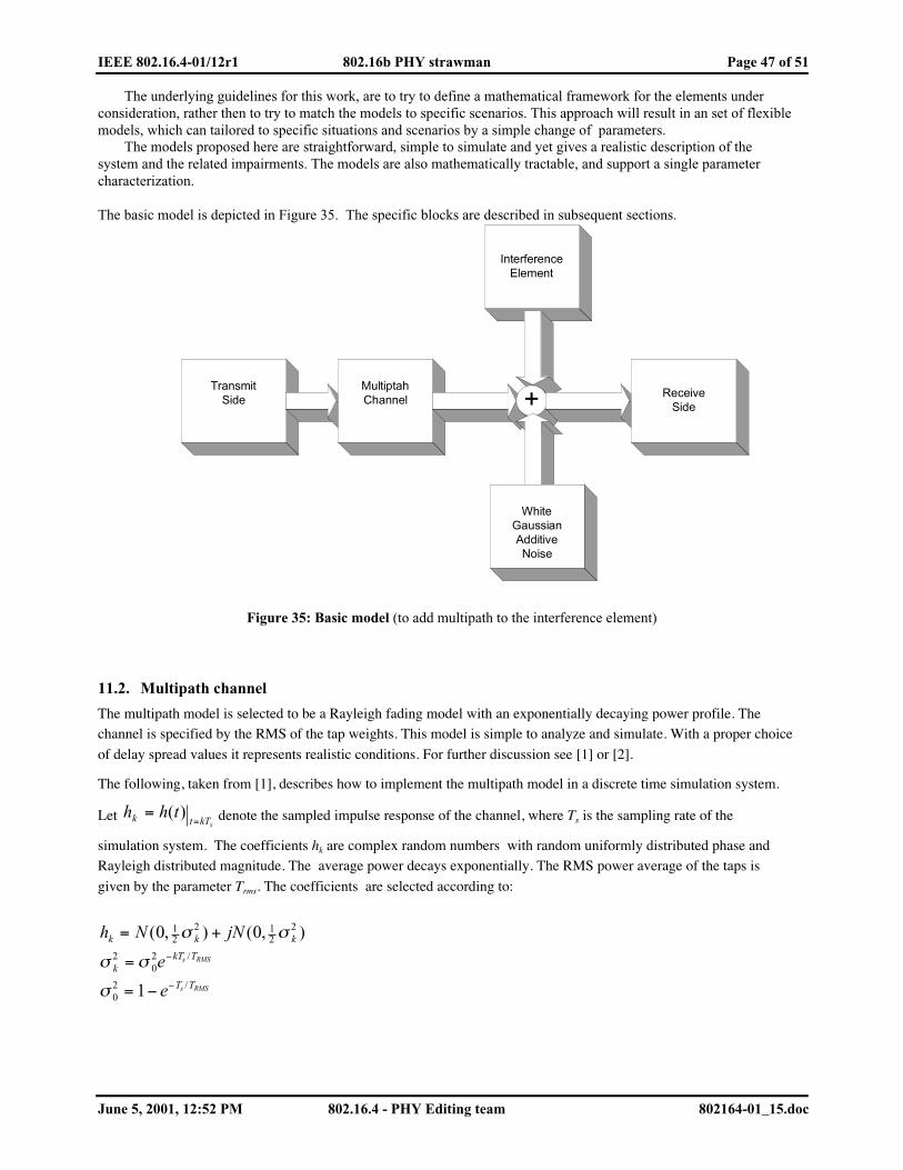
IEEE 802.16.4-01/12r1 802.16b PHY strawman Page 47 of 51
June 5, 2001, 12:52 PM 802.16.4 - PHY Editing team 802164-01_15.doc
The underlying guidelines for this work, are to try to define a mathematical framework for the elements underconsideration, rather then to try to match the models to specific scenarios. This approach will result in an set of flexiblemodels, which can tailored to specific situations and scenarios by a simple change of parameters.
The models proposed here are straightforward, simple to simulate and yet gives a realistic description of thesystem and the related impairments. The models are also mathematically tractable, and support a single parametercharacterization.
The basic model is depicted in Figure 35. The specific blocks are described in subsequent sections.
InterferenceElement
TransmitSide
MultiptahChannel +
WhiteGaussianAdditiveNoise
ReceiveSide
Figure 35: Basic model (to add multipath to the interference element)
11.2. Multipath channel
The multipath model is selected to be a Rayleigh fading model with an exponentially decaying power profile. Thechannel is specified by the RMS of the tap weights. This model is simple to analyze and simulate. With a proper choice
of delay spread values it represents realistic conditions. For further discussion see [1] or [2].
The following, taken from [1], describes how to implement the multipath model in a discrete time simulation system.
Let skTtk thh
== )( denote the sampled impulse response of the channel, where Ts is the sampling rate of the
simulation system. The coefficients hk are complex random numbers with random uniformly distributed phase andRayleigh distributed magnitude. The average power decays exponentially. The RMS power average of the taps is
given by the parameter Trms. The coefficients are selected according to:
h N jN
e
e
k k k
kkT T
T T
s RMS
s RMS
= +
=
= −
−
−
( , ) ( , )/
/
0 0
1
12
2 12
2
202
02
σ σ
σ σ
σ
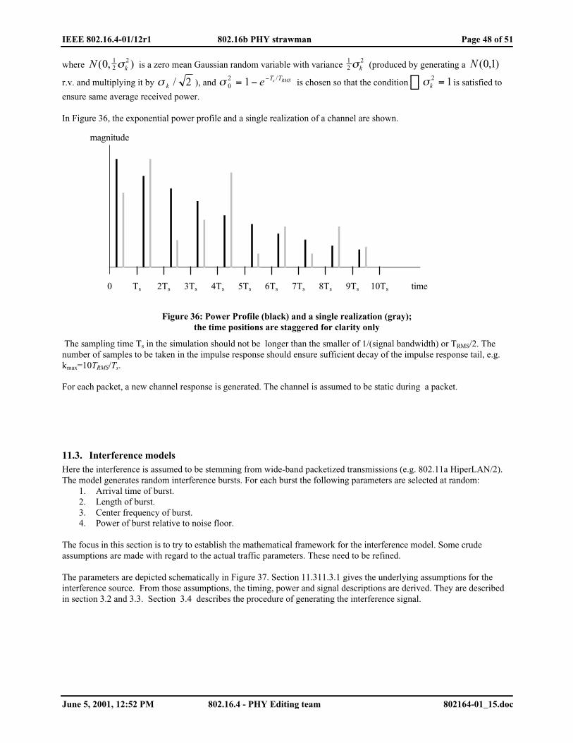
IEEE 802.16.4-01/12r1 802.16b PHY strawman Page 48 of 51
June 5, 2001, 12:52 PM 802.16.4 - PHY Editing team 802164-01_15.doc
where N k( , )0 12
2σ is a zero mean Gaussian random variable with variance 12
2σk (produced by generating a N ( , )0 1
r.v. and multiplying it by σ k / 2 ), and σ 02 1= − −e T Ts RMS/ is chosen so that the condition σk
2 1� = is satisfied to
ensure same average received power.
In Figure 36, the exponential power profile and a single realization of a channel are shown.
magnitude
time 10Ts 9Ts 8Ts 7Ts 6Ts 5Ts 4Ts 3Ts 2Ts Ts 0
Figure 36: Power Profile (black) and a single realization (gray);the time positions are staggered for clarity only
The sampling time Ts in the simulation should not be longer than the smaller of 1/(signal bandwidth) or TRMS/2. Thenumber of samples to be taken in the impulse response should ensure sufficient decay of the impulse response tail, e.g.kmax=10TRMS/Ts.
For each packet, a new channel response is generated. The channel is assumed to be static during a packet.
11.3. Interference modelsHere the interference is assumed to be stemming from wide-band packetized transmissions (e.g. 802.11a HiperLAN/2).The model generates random interference bursts. For each burst the following parameters are selected at random:
1. Arrival time of burst.2. Length of burst.3. Center frequency of burst.4. Power of burst relative to noise floor.
The focus in this section is to try to establish the mathematical framework for the interference model. Some crudeassumptions are made with regard to the actual traffic parameters. These need to be refined.
The parameters are depicted schematically in Figure 37. Section 11.311.3.1 gives the underlying assumptions for theinterference source. From those assumptions, the timing, power and signal descriptions are derived. They are describedin section 3.2 and 3.3. Section 3.4 describes the procedure of generating the interference signal.

IEEE 802.16.4-01/12r1 802.16b PHY strawman Page 49 of 51
June 5, 2001, 12:52 PM 802.16.4 - PHY Editing team 802164-01_15.doc
cene
ter
freq
uenc
y
starttime
802.16.b trasnmission
Interference
desired signal
tD duration
pow
er
Time
Frequency
Power
Figure 37: Interference parameters
11.3.1. Basic assumptions
Here we shall assume that the interferer is a 802.11a like signal (see [3]). The instantaneous transmission rate is24Mb/s. The occupied bandwidth is about 17MHz. The PHY layer overhead per packet is assumed to be 20uSec.
For the interferer traffic, we shall use the results published in [4], where histograms of Ethernet packet sizes areshown. It is demonstrated that almost 75% of the packets are shorter than 522 bytes and nearly half the packets are 40-44bytes. In order to simplify and to reach round numbers, we shall assume that the packet size is uniformly distributedin the range 48 480bytes. This is equivalent to a packet duration in the range of 36 180 uSec.
The time between consecutive interference bursts is can be computed as follows. From [4], we can assume that mosttraffic, in bytes, is concentrated in long packets, say in 500bytes packets. Let us assume a channel utilization of 25%.Thus the average idle channel time is (1-0.25)/0.25*500*8/24Mb/s= 500uSec.Here we shall assume that the average time from end of interference burst to beginning of next burst is Poissondistribution with a mean of 500uSec.
It is assumed that the power spectral density (PSD) of the interference is in the same order of magnitude as the thermalnoise floor. More specifically, the PSD is in the range of N0 to N0+20dB, where N0 is the thermal noise floor.(—174dBm/Hz).The frequency offset between the interferer and the desired signal is uniformly distributed in the range -10Mhz +10MHz.
11.3.2. Signal Wave shape
The interference signal is generated by passing a white complex Gaussian process, through a raised cosine filter andamplifying it to the desired level. Then it is shifted in frequency in to a randomly selected center frequency.The motivation for using this wave shape is as follows:
• The proposed signal is easy to generate• The spectral signature is similar to that of many communication systems.• It has roughly the same peak to average power ratio as that of an OFDM signal.• This signal, can be easily modified to represent other interfering signals.
The parameters of the raised cosine filter are rolloff factor of β=0.25 and 6dB corner of fc=10MHz. The filter is givenby:
( )
( ) ( )��
��
�
+<≤−���
�
���
�√√↵
����
−−
−<
=cc
c
c
ffff
f
ff
fHβββ
π
β
1112
sin12/1
11
)(

IEEE 802.16.4-01/12r1 802.16b PHY strawman Page 50 of 51
June 5, 2001, 12:52 PM 802.16.4 - PHY Editing team 802164-01_15.doc
11.3.3. Generating Procedure
The signal generation is depicted in Figure 38. The procedure for generating the interference is given below.
H(f) X
G=10α/20
N0 Take segmenttd
X
exp(2π fi t)
Figure 38: Generating the interference signal
1. Select the start time. Generate a poisson random variable t0 with a mean of 1/λ= 500uSec according to theprobability distribution function given by :
tt ettf λλ −=)( .
2. Add t0 to the end of the last interference Burst. If this is the first interference burst, t0 signifies start time frombeginning of transmission burst.
3. Select the duration. Generate a uniformly distributed random tD variable in the range 36uSec...180uSec.4. Generate a white gaussian noise process with double sided PSD of N0.5. Filter the noise process with H(f) given above.6. Select center frequency, fi in the range —10MHz 10MHz.7. Shift the signal in frequency by multiplying it by exp(j2π fi t).8. Select amplification. Generate a random variable α, uniformly distributed in the range 0 20. Set the
amplification to G=10α/20.
9. Take a segment of tD of the generated signal. Add it to the desired signal at the start time selected in steps 1and 2.
10. Repeat with step 1.
11.4. Radio ImpairmentsThe radio impairments models consist of phase noise models and power amplifier non-linearties.
11.4.1. Power amplifier non-linearity (to add AM-PM distortion)
The power amplifier model is based on the well-known Rapp’s model ([5]) with knee parameter P=2. Besides its
simplicity, the model well represents typical power amplifiers at the sub 10GHz range.
Consider using a complex baseband notation. Denote by vIN and vOUT the input and output complex signals,
respectively. Let P vSAT SAT=| |2 denote let the saturated power of the amplifier be P vSAT SAT=| |2 . Then the relation
between vIN and vOUT is given by:
( )( ) 2,/||1)2/(12 =+= Pvvvv
PPSATININOUT .

IEEE 802.16.4-01/12r1 802.16b PHY strawman Page 51 of 51
June 5, 2001, 12:52 PM 802.16.4 - PHY Editing team 802164-01_15.doc
11.4.2. Phase noise
For the phase noise simplified phase noise model is selected. While maintaining a simple description the modeladequately represent the behavior of typical microwave phase-locked loop oscillator.
The phase noise is presented as white gaussian noise process for which is driven through a single pole low pass filter.
The 3dB corner of the low-pass should be set at 10KHz, which is a typical value for large step oscillators. A typicalPSD is shown in Error! Reference source not found..
The model ignores the contribution of the oscillator phase noise, which can be easily tracked and the effects of phasenoise PSD flattening in high frequencies.
For simplicity it is recommended that the phase noise effects shall be simulated only on the transmitter side.
10KHz
PSD
Frequency
20dB/decade
Figure 39: Phase noise PSD
11.5. AcknowledgementsIt is a pleasure to acknowledge Dr. Vladimir Yanover for his assistance with the Caida database.
11.6. References[1] IEEE802.11a 802.11-98/156r2 Updated submission template for Tga —revision 2.
[2] C. Tellambura, Y.J. Guo and S.K, Barton: Equalizer Performance for HiperLAN Indoor channels , WirelessPersonal Comuunications vol. 3, pp. 397-410 Feb. 1996.
[3] IEEE 802.11 Wireless LAN standard: high speed Physical layer in the 5Ghz Band.
[4] http://www.caida.org/outreach/papers/Inet98/
[5] Rapp, C. Effects of HPA non-linearity on 4-DPSK/OFDM Signal for Digital Sound Broadcasting SystemProceedings of the Second European Conference on Satellite Communications, Liege Belgium pp.179-184, Oct 22-241991.
12. Annex B — MAC - PHY interface (Radu — Itzik, Jori, + Editing Team)