iec contactors and overload relays - amazon s3 · april 2005 tdo3400001u 2 a.c. operating coils -...
TRANSCRIPT

IEC Contactors and Overload Relays
Technical Solutions Mini Series Contactors and Overload Relays
Freedom Series Contactors and Overload Relays
Modular Series Contactors and Overload Relays
Mini Series Contactors and Overload Relays
Contactors 2
Contactors – reversing 2
Accessories 3
Technical data 4
Lighting circuit switching 6
Overload relay 7
Technical data 7
Dimensions 8
Freedom Series Contactors and Overload Relays
Contactors 10
Accessories 11
Thermal overload relays 14
Type 2 Co-ordination Selection procedure 16
Technical data 18
Dimensions 33
Modular Series Contactors and Overload Relays
Contactors 38
Accessories 40
Technical data 42
Dimensions 47
Thermal overload relays 49
Technical data 50
Dimensions 54

www.eatonelectrical.com
April 2005
TDO3400001U
2
A.C. operating coils - 3.5VA
Coil voltage Suffix40 to 450Hz
24 T48 W110 - 127 A220 - 240 B277 H380 - 415 L
Contactors
AC3 rating 3ph Number of contacts Catalogue400/440V Main Auxiliary numbers
4kW3 N.O. 1 N.O. CE12BNC310*3 N.O. 1 N.C. CE12BNC301*4 N.O. CE12BNC400*
5.5kW3 N.O. 1 N.O. CE12CNC310*3 N.O. 1 N.C. CE12CNC301*4 N.O. CE12CNC400*
D.C. operating coils - 3.5 watts
Coil voltage Suffix
12 R124 T148 W1110 - 125 A1220 - 240 B1
D.C. low power consumption operating coils for non-reversingcontactors
Coil voltage Suffix
24 (1.4 watts) T224 (1.7 watts with surge suppressor) T317 - 32 (2.4 watts) V217 - 32 (2.8 watts with surge suppressor) V3
Can not be used when auxiliary contacts are fitted.
Contactors – Reversing
AC3 rating 3ph Number of contacts Catalogue400/440V Main Auxiliary numbers
4kW3 N.O. 1 N.O. CE52BNC310*3 N.O. 1 N.C. CE52BNC301*
5.5kW3 N.O. 1 N.O. CE52CNC310*3 N.O. 1 N.C. CE52CNC301*
* Add suffix for coil voltage from the tables below
Mini Series Contactors and Overload Relays
Catalogue numbers
Mini Series – 4 and 5.5kW

www.eatonelectrical.com
April 2005
TDO3400001U
3
Auxiliary Contacts ➀
Description Contact Catalogueconfiguration numbers
Side mounting 1 N.O. 1 N.C. C320MCS11
Top mounting 1 N.O. 1 N.C. C320MCF112 N.O. C320MCF202 N.C. C320MCF02
➀Top and side mounted auxiliary contact blocks can not be used together.
Accessories
Description Voltage Cataloguenumbers
Supressors 24 - 60Vdc C320MSS150 - 250Vdc C320MSS2200 - 420Vdc C320MSS3
Identification markers C320MCM1
Mini Series Contactors and Overload Relays
Catalogue numbers - Accessories
Mini Series – 4 and 5.5kW

www.eatonelectrical.com
April 2005
TDO3400001U
4 Mini Series Contactors and Overload Relays
Technical data – ContactorsContactor CE12BN & CE52BN CE12CN & CE52CNSpecifications IEC 947-4-1, IEC947-5-1 IEC947-4-1
Rated insulation voltage Ui 690V 500V
Air temperature (close to contactor)Fitted with a thermal O/L relay 25 to +50¡C 25 to +50¡C
Without thermal O/L relay 25 to +55¡ 25 to +55¡C
For storage 40 to +80¡C 40 to +80¡C
Climatic withstandAcc. to DIN 50 017 Humidity in alternative climate Humidity in alternative climate KFWAcc. to UTE C 63-100 30 cycles, specification 1 30 cycles, specification 1
Mounting positions All positions All positions
Mechanical durabilityOperating cycles 10 million 10 million
Maximum switching frequencyAC-1 300 cycles/h 300 cycles/h
DC-1, DC-3, DC-5, AC-2, AC-3, AC-15, DC-13 600 cycles/h
Rated operational voltage Ue 12 - 500V ac 12 - 500V ac
Rated operational current Ie/AC-1, AC-3 AC-1/Ie (A) AC-2, AC-3 AC-1/Ie (A) AC-2, AC-3Rated operational power at: 55¡C 40¡C Ie (A) P (kW) 55¡C 40¡C Ie (A) P (kW)
220/240V 16 20 9 2.2 16 20 12/11 3380/440V 16 20 9/8 4.0 16 20 12/11 5.5500V 12 12 5.5 3.0 12 12 7.0 4
Shock withstand 1/2 sinusoidal shock for 10ms: 1/2 sinusoidal shock for 10ms:Standard mounting position: position 1 no change in contact position no change in contact position
Shock directions A B1 B2 C1 C2 A B1 B2 C1 C2Making position 20g 20g 20g 20g 20g 20g 20g 20g 20g 20gBreaking position 10g 20g 20g 20g 20g 10g 20g 20g 20g 20g
Operating time B6 BC6 K6 KC6 B7 BC7Between coil energisation and: (ms) (ms) (ms) (ms) (ms) (ms)
N.O. contact closing/N.C. contact opening 14 - 26 14 - 26 14 - 26 14 - 26 14 - 26 14 - 26
Between coil de-energisation and:N.O. contact opening/N.C. contact closing 16 - 40 4 - 10 16 - 40 4 - 10 16 - 40 4 - 10
Heat dissipation per pole 2W at 20A 2W at 20A
Short-circuit protection(for contactors without add-on thermal O/L relay)
Type fuses gG (gl) - co-ordination:Type 1 20A 25AType 2 20A 20A
Coil consumption (average value)ac pull-in/holding 3.5VA 3.5VAdc pull-in/holding 3.5W 3.5W
Technical data – Built-in or add-on auxiliary contact blocksRated operational voltage Ue 12 - 240V dc
12 - 500V ac
Conventional free air thermal current Ith 6A
Short-circuit protection, type fuses gG (gl) 10A
Rated operational current Ie / AC-15220/240V 4A380/440V 3A500V 2A
Rated operational current Ie / DC-1324V 1.5A60V 0.5A110V 0.4A220/240V 0.04
Min. switching capacity of auxiliarycontacts ⊕ 17V and ⊕ 5mA
Mini Series – 4 and 5.5kW

www.eatonelectrical.com
April 2005
TDO3400001U
5Mini Series Contactors and Overload Relays
Technical data
Electrical durability curves for DC-1, DC-3 & DC-5The curves below take into account the time constant L/R for each utilisationcategory and show the electrical drability of the contactors during DC-1, DC-3and DC-5 use for three poles connected in series.
If one single pole is used, the corresponding breaking capacity (W) is reducedto 1/3 and for two poles connected in series it is reduced to 2/3.
A = DC-1 3 poles in series C = DC- 5 3 poles in seriesB = DC-3 3 poles in series
AC Electrical endurance curves4kW contactors – AC1 & AC3 duty 4kW contactors – AC4 duty
5.5kW contactors – AC1 & AC3 duty 5.5kW contactors – AC4 duty
DC power circuit switchingUtilisation category DC-1 DC-3 DC-5
L/R ⊕ 1ms L/R ⊕ 2ms L/R ⊕ 7.5ms
24V 16A 16A 16A48V 16A 8.0A 2.0A60V 16A 4.0A 1.25A110V 7.0A 1.5A 0.4A220V 0.8A 0.25A 0.2A
24V 16A 16A 16A48V 16A 16A 16A60V 16A 15A 12A110V 16A 7.0A 2.0A220V 5.0A 1.5A 0.5A
24V 16A 16A 16A48V 16A 16A 16A60V 16A 16A 16A110V 16A 15A 8.0A220V 14A 4.0A 2.0A
+ –
+ –
+ –
Mini Series – 4 and 5.5kW

www.eatonelectrical.com
April 2005
TDO3400001U
6
Lighting circuit switchingThe table below shows the number of lamps per phase in 230V 50Hz for the main poles (terminals marked 1 to 8):Note that overshooting of the announced capacitive loads may generate on energisation unacceptable current peaks.
Other factors may influence peak amplitude on energisation.
● Lengths and cross sections of installation conductors● Electronic arcing devices● Lamp maufacture
For these reasons, the values in the following tables are given for information only.
Type of lamps Characteristics Number of lamps CapacitiveIn per phase load
(W) (A) (230V, 50Hz) in µF
Incandescent 60 0.26 20lamps 10 0.43 12
200 0.87 6300 1.30 4500 2.17 21000 4.35 1
Flourescent Without compensation and series compensationlamps 15 0.35 25
20 0.37 2340 0.43 2058 0.67 1665 0.67 12115 1.5 5140 1.5 5
Two lamp circuit2 x 20 1 x 0.13 2 x 262 x 40 1 x 0.22 2 x 202 x 58 1 x 0.32 2 x 162 x 65 1 x 0.34 2 x 122 x 115 1 x 0.65 2 x 52 x 140 1 x 0.75 2 x 5
Parallel compensation15 0.11 7 4.520 0.13 6 4.540 0.22 7 4.558 0.32 5 765 0.34 4 7115 1.65 1 18140 1.75 1 18
High pressure Without compensationmercury 50 0.61 10vapour 80 0.8 7lamps 125 1.15 5eg HQL, HPL 250 2.15 3
400 3.25 2700 5.40 1
Parallel compensation50 0.28 10 780 0.41 7 8125 0.65 5 10250 1.22 3 18400 1.95 2 25700 3.45 451000 4.8 60
Lamps with 1 x 18 17electronic 2 x 18 8ignition 1 x 36 11device 2 x 36 6
1 x 56 112 x 58 6
Dualmounting
Type of lamps Characteristics Number of lamps CapacitiveIn per phase load
(W) (A) (230V, 50Hz) in µF
Metal Without compensationIodide 35 0.53 10lamps 70 1.0 5eg HGI, HPI 150 1.8 3
250 3.0 2400 3.5 1
Parallel compensation35 0.25 6 670 0.45 3 12150 0.75 1 20250 1.5 1 33400 2.5 1 35
low pressure Without compensationsodium lamps 35 1.5 4
55 1.5 490 2.4 2135 3.5 2150 1.0 2180 3.3 2200 2.3 2
Parallel compensation35 0.31 2055 0.42 2090 0.63 30135 0.94 45150 1.0 40180 1.16 40200 1.32 25
High pressure Without compensationsodium lamps 150 1.8 3
250 3.0 2330 3.7 2400 4.7 1
Parallel compensation150 0.83 20250 1.5 33330 2.0 40400 2.4 481000 6.3 106
Transformers Transformer Number of transformersfor low voltage power per phasehalogen (W) (230V, 50Hz)lamps
20 4050 2075 13100 10150 7200 5300 3
Mini Series Contactors and Overload Relays
Mini Series – 4 and 5.5kW

www.eatonelectrical.com
April 2005
TDO3400001U
7Mini Series Contactors and Overload Relays
Catalogue numbers
Mini Series – Overload Relay
Technical data
Motor FLA in Amperes Catalogue Number .10 – .16 C312AN3A .16 – .24 C312AN3B .24 – .40 C312AN3C .40 – .60 C312AN3D .60 – 1.00 C312AN3E1.00 – 1.60 C312AN3F1.60 – 2.40 C312AN3G2.40 – 4.0 C312AN3H4.0 – 6.0 C312AN3J6.0 – 9.0 C312AN3K9.0 – 12.0 C312AN3L
Overload relays to be used with Pressure Plate Terminal type Mini Contactors only.
Thermal Overload Relay C312 —
Conformity to Standards¥ IEC 947-4-1, 947-5-1, CE¥ UL 508, CSA 22.2
Thermal (Bimetallic) Overload Relay, C312 OL Relay¥ Insulation Voltage (Ui): 690V AC¥ Rated Operational Voltage (Ue): 690V AC¥ Ambient Temperature: -13° to 122°F (-25° to +50°C) temperature
compensated¥ Storage: -40° to 158°F (-40° to +70°C)
¥ Impulse Withstand Voltage (Uimp): 6 kV¥ Climatic Resistance —
¥ Acc. to DIN 50 017¥ Acc. to UTE C 63 – 100: IEC 68-2-3, IEC 68-2-30
¥ Mounting Position: ± 30 from vertical position, not horizontal, notupside down, 5 mm side by side mounting distance
¥ Switching Frequency with Avoidance of Nuisance Trippings —max. ops./h: 15
¥ 40% ED — max. ops./h: 60 (if 6X in startup time 1 s)¥ Overvoltage Category/Pollution Degree: III/3¥ Safe Isolation to IEC 536: 300V AC¥ Conventional Free Air Thermal Current (Ith): 6.0A
Terminal Capacities
Description SpecificationSolid mm 2X (.75X – 2.5) mmFlexible with Ferrule mm 2X (.5X – 1.5) mmSolid or Stranded AWG 2X (18X –12)
Trip Contact Ratings AC-15
Operating Voltage (Ue) 120V 220/240V 380/415V 500VRated Operational Current (Ie) Contacts 95 – 96 — NC (Break) – 1.5A .7A .5A Contacts 97 – 98 — NO (Make) – 1.5A .5A .3A
Trip Contact Ratings DC-13
Operating Voltage (Ue) 24V DC 60V DC 110V DC 220V DCRated Operational Current (Ie) Contacts 95 – 96 — NC (Break) .9A .5A .3A .1A Contacts 97 – 98 — NO (Make) .9A .5A .3A .1A
Setting Variances

www.eatonelectrical.com
April 2005
TDO3400001U
8
Reversing contactorsContactor
Contactor with top mounted auxiliaryContactor with side mounted auxiliary
Mounting dimensions
Mini Series Contactors and Overload Relays
Mini Series – 4 and 5.5kW
Dimensions (mm)

www.eatonelectrical.com
April 2005
TDO3400001U
9
Dimensions (mm)
Top mounted auxiliary contactSide mounted auxiliary contact
Mini Series Contactors and Overload Relays
Mini Series – 4 and 5.5kW
Mini contactor and overload relay

www.eatonelectrical.com
April 2005
TDO3400001U
10
Mounting positions of auxiliary contactsContactors CE15LN to NN are supplied with R1 fitted.Contactors CE15PN to SN with ac coils are supplied withL1 fitted. With dc coils L1 and L2 are fitted.By attaching combinations of top and side mounted auxiliary contact blocksup to 8 additional circuits may be added.CE15AN to CE15KN up to 8 N.O. or 4 N.O. - 4 N.C.CE15LN to CE15SN maximum 6 N.O. or 6 N.C. in any one configuration
Catalogue numbers – ContactorsAC3 rating 3 ph Number of contacts Catalogue numbers380/440V (kW) Main Auxiliary AC operated DC operated
2.2 3 N.O. 1 N.O. CE15ANS3* –3 N.O. 1 N.C. CE15ANC3* –4 N.O. CE15AN4* –
4 3 N.O. 1 N.O. CE15BNS3* CE15BNS3*3 N.O. 1 N.C. CE15BNC3* –4 N.O. CE15BN4* –
5.5 3 N.O. 1 N.O. CE15CNS3* CE15CNS3*3 N.O. 1 N.C. CE15CNC3* –4 N.O. CE15CN4* –
7.5 3 N.O. CE15DN3* CE15DNS3*11 3 N.O. CE15EN3* CE15ENS3*15 3 N.O. CE15FN3* CE15FNS3*
18.5 3 N.O. CE15GN3* CE15GNS3*22 3 N.O. CE15HN3* CE15HNS3*30 3 N.O. CE15JN3* CE15JNS3*37 3 N.O. CE15KN3* CE15KNS3*
45 3 N.O. 1 N.O. CE15LN3* CE15LNS3*55 3 N.O. 1 N.O. CE15MN3* CE15MNS3*75 3 N.O. 1 N.O. CE15NN3* CE15NNS3*
90 3 N.O. 1 N.O. 1 N.C. MCE15PN3* MCE15PNS3*110 3 N.O. 1 N.O. 1 N.C. MCE15RN3* MCE15RNS3*160 3 N.O. 1 N.O. 1 N.C. MCE15SN3* MCE15SNS3*
* Add suffix from tables on page 11 to select coil voltage required. For voltages not shown contact Head Office.
Freedom Series Contactors and Overload Relays
Freedom Series – 2.2 to 160kW

www.eatonelectrical.com
April 2005
TDO3400001U
11
Catalogue numbers – AccessoriesAuxiliary contact blocks – top mounting (maximum 1 per contactor)
Contact Contactor type Catalogueconfiguration numbers
1 N.O. CE15A to CE15K C320KGT11 N.C. C320KGT2
1 N.O. 1 N.C. C320KGT32 N.O. C320KGT4
2 N.C. C320KGT52 N.O. 2 N.C. C320KGT153 N.O. 1 N.C. C320KGT144 N.O. C320KGT13
Auxiliary contact blocks – side mounting (maximum 2 per contactor)Contact Mounting Contactor Catalogueconfiguration position ✝ type numbers
1 N.O. L1, R1 CE15AN to KN C320KGS11 N.C. L1, R1 C320KGS2
1 N.O. 1 N.C. L1, R1 C320KGS32 N.O. L1, R1 C320KGS4
Auxiliary contact blocks – base mountingContact Mounting Contactor Catalogueconfiguration position ✝ type numbers
1 N.O. L1, R1 CE15LN to NN C320KGS311 N.O. 1 N.C. L1, R1 CE15LN to NN C320KGS321 N.O. L1, R1 CE15PN to SN C320KGS411 N.O. 1 N.C. L1, R1 CE15PN to SN C320KGS42
Auxiliary contact blocks – add-on
Contact Mounting Contactor Catalogueconfiguration position ✝ type numbers
1 N.O. L2, L3, R2, R3 CE15LN to SN C320KGS201 N.C. L2, L3, R2, R3 C320KGS21
1 N.O. 1 N.C. L2, L3, R2, R3 C320KGS22
✝ Mounting postions of auxiliary contacts (See page 33)
A.C. Operating coilsCoil 50Hz 24 48 110 220 240 380 415 440 550voltage 60Hz - - 120 240 - - - 480 600
CE15AN to FN T Y A B K L M C D
CE15GN to SN U Y A B K L M C D
D.C. operating coils for contactors 4 to 15 & 45kW to 75kW onlyCoil voltage 12 24 48 120
Suffix code R1B T1B W1B A1B
D.C. Operating coils for contactors 18.5 to 37kW onlyCoil voltage 12 24 48 120
Suffix code R4B T4B W4B A4B
D.C. Coil elementary diagram for contactors 4 to 15kW
D.C. Operating coils for contactors 90 to 160kW onlyCoil voltage 24 48 120 240
Suffix code T1B W1B A1B B1B
NoteDC operating coils come complete with encapsulated coil,1N.C. early opening side auxiliary and connection wiring.
Freedom Series Contactors and Overload Relays
Suffixcode
Freedom Series – 2.2 to 160kW

www.eatonelectrical.com
April 2005
TDO3400001U
12
Catalogue numbers – Accessories (continued)
Description For contactor Cataloguetype numbers
Pneumatic timer – top mountingAdjustable range CE15AN to KN(On or off delay)
0.3 to 30 secs. C320TP110 to 180 secs. C320TP2
Note: When timer is used, other top mounting auxiliaries cannot be added.
Mechanical interlockWhen fitted, auxiliary contacts CE15AN to KN C321KM60Bcan be added to one side ofthe contactor only. CE15LN to NN C321KM30
MCE15PN to SN C321KM40
Coil surge suppressorTo suppress operating coilswitch-off surge.Control supply 50-60Hz
24 48V CE15AN to KN MC320LRC5110 240V CE15AN to KN MC320LRC2110 240V CE15LN to NN MC320LRC3110 240V MCE15PN to SN MC320LRC3
35mm DIN mounting rail1 metre length CE15AN to GN MC382MA1
Identification markerPack of 100 CE15AN to KN C320DL2
Reversing connections kitComprises mechanical interlock and a CE15AN to CN C321KM60K14Bpre-cut trimmed and formed wire set. CE15DN to FN C321KM60K13B
CE15GN to KN C321KM60K16BCE15LN to NN C321KM60K21 ✝MCE15PN to SN C321KM60K19 ✝
Termination kits for main contactsFor crimp terminal lugs to allowconnection of up to 2 additionalcables for reversing or star/delta duty. CE15LN to NN C325MTK
Extension plates for reversing connections. MCE15PN to SN MC321TE3
Finger protection shieldsShields to prevent accidental contact withline/load terminals.
Standard mounting CE15LN to NN MC321FK1Side mounting MC321FK2Side mounting with overload relay fitted MC321FK3
Standard or side mounting with or without MCE15PN to SNoverload relay fitted MC321FK4
✝ Kit includes 2 off N.C. auxiliary contact blocks.
C321M60B C321KM30
Freedom Series Contactors and Overload Relays
Freedom Series – 2.2 to 160kW

www.eatonelectrical.com
April 2005
TDO3400001U
13
Catalogue numbers – Accessories (continued)
Description For contactor Cataloguetype numbers
Main contact renewal kitCE15GN3 6-65-4CE15HN3 6-65-6CE15JN3 6-65-8CE15KN3 6-65-17CE15LN3 6-43-4CE15MN3 6-43-2CE15NN3 6-43-6CE15NN 6-293MCE15PN 6-294MCE15RN 6-288MCE15SN 6-286
Freedom Series Contactors and Overload Relays
Freedom Series – 2.2 to 160kW
Replacement operating coils – AC (See note below)Coil voltage Catalogue numbers50Hz 60Hz CE15AN to CN CE15DN to FN CE15GN to KN CE15LN to NN MCE15PN to SN
24 MC15CWU MC15FWU MC15KWU MC15WU 9-2412-5A48 MC15CWY MC15FWY MC15KWY MC15WY 9-2412-8A110 120 MC15CWA MC15FWA MC15KWA MC15WA 9-2412-1A220 240 MC15CWB MC15FWB MC15KWB MC15WB 9-2412-2A240 MC15CWK MC15FWK MC15KWK MC15WK 9-2412-13A380 MC15CWL MC15FWL MC15KWL MC15WL 9-2412-14A415 MC15CWM MC15FWM MC15KWM MC15WM 9-2412-16A440 480 MC15CWC MC15FWC MC15KWC MC15WC 9-2412-3A550 600 MC15CWD MC15FWD MC15KWD MC15WD 9-2412-4ANote:Replacement operating coils are for use with current series 'B' contactors.For replacement coils for previous series 'A' contactors please contactEaton.

www.eatonelectrical.com
April 2005
TDO3400001U
14 Freedom Series Contactors and Overload Relays
For direct connection with CE15AN to FN contactors or independent mounting
Description Motor FLC range A Catalogue numbers
Relay with 1 N.O. 1 N.C. electrically separate contacts, 0.25 0.4 C316FNA3Cselectable hand or auto reset with reset or stop-reset option, 0.4 0.63 C316FNA3Dphase loss protection and trip indicator. 0.63 1.0 C316FNA3E
1.0 1.4 C316FNA3F1.3 1.8 C316FNA3G1.7 2.4 C316FNA3H2.2 3.1 C316FNA3J2.8 4.0 C316FNA3K3.5 5.0 C316FNA3L4.5 6.5 C316FNA3M6.0 8.5 C316FNA3N7.5 11.0 C316FNA3P10 14.0 C316FNA3Q13 19.0 C316FNA3R18 24.0 C316FNA3S24 32.0 C316FNA3T
Separate base for independent connectionand DIN rail or panel mounting C306TB1
For direct connection with CE15GN to KN contactors or independent mounting
Relay with 1 N.O. 1 N.C. electrically separate contacts, 18 25 C316KNA3Aselectable hand or auto reset with reset or stop-reset option, 22 32 C316KNA3Bphase loss protection and trip indicator. 29 42 C316KNA3C
36 52 C316KNA3D45 63 C316KNA3E60 80 C316KNA3F
Separate base for independent connectionand panel mounting C316TB1
Catalogue numbers – Thermal overload relays
Note: For star-delta applications multiply motor FLC by 0.58
Freedom Series – 2.2 to 160kW

www.eatonelectrical.com
April 2005
TDO3400001U
15Freedom Series Contactors and Overload Relays
Catalogue numbers – Thermal overload relays (continued)
For independent mounting and connection with CE15LN to PN contactors
Description Motor FLC range A Catalogue numbers
Relay with 1 N.O. 1 N.C. electrically separate contacts, 65 90 C316PNA3Aselectable hand or auto reset with reset or stop-reset option, 80 110 C316PNA3Bphase loss protection and trip indicator. 100 135 C316PNA3C
110 150 C316PNA3D130 175 C316PNA3E150 200 C316PNA3F
Set of connecting links To contactors CE15LN to NN3 C316MCL To contactors CE15PN C316PCL
Current transformer operated for independent connection with CE15RN to SN contactors
Relay with 1N.O. 1N.C. electrically separate contacts, 130 185 C316SNA3Aselectable hand or auto reset with reset or stop-reset 165 235 C316SNA3Boption, phase loss protection and trip indicator. 220 310 C316SNA3C
285 400 C316SNA3D
Identification marker (pack of 50) C316MT1
Remote reset moduleDescription Operating voltage Catalogue numbers
50/60HZ
For use with thermal overload relays C316FNA3, 220/440 C316RR1Nand C316SNA3
Note: For star-delta applications multiply motor FLC by 0.58
Freedom Series – 2.2 to 160kW
Operating timeMinimum: 0.2 secsMaximum: 0.3 secs
Inrush VAOperating voltage Inrush VA220/440 412

www.eatonelectrical.com
April 2005
TDO3400001U
16 Freedom Series Contactors and Overload Relays
Type 2 co-ordination selection procedure
Step 1.Determine the motor Full Load Current (FLC) from Table 1.
Step 4.Select overload relay and note it's fuse link rating from table 4.
Step 2.Decide method of starting and then note the fuse link rating whichcorresponds to the Motor FLC from table 2a (Direct on Line) or2b (Star Delta starting).
Step 5.Compare the fuse link rating noted in step 2 with the lowest of the ratingsnoted in steps 3 and 4.
ExampleStep 2 - Motor = 16AStep 3 - Contactor = 16AStep 4 - Overload relay = 20A
If this lowest value is less thanthe fuse link rating noted instep 2, then Type 2co-ordination is not achieved.
NOType 2 Co-ordinationis not achieved.
If this lowest value is equal toor greater than the fuse linkrating noted in step 2, thenType 2 co-ordination isachieved.
YESType 2 Co-ordinationis achieved.
Step 3.Select contactor and note it's fuse link rating from table 3.
Freedom Series – 2.2 to 160kW
Table 4. Eaton Freedom Seriesoverload relays
Table 4. Eaton Freedom Seriescontactors

www.eatonelectrical.com
April 2005
TDO3400001U
17Freedom Series Contactors and Overload Relays
Table 1. Motor full load currentkW HP 220V 380V 415V1.1 1.0 4.9 2.9 2.61.5 2.0 6.3 3.6 3.32.2 3.0 9.0 5.2 4.83.0 4.0 12 6.8 6.24.0 5.5 16 9.1 8.35.5 7.5 21 12 117.5 10 27 16 1410 13.5 36 21 1911 15 40 23 2115 20 52 30 2818.5 25 64 37 3422 30 77 44 4130 40 100 59 5437 50 125 73 6745 60 150 86 7955 75 180 106 9875 100 240 140 13090 125 300 170 160110 150 350 200 190132 175 410 240 220160 220 510 300 270
Table 2a. D.O.L. fuse link ratingMotor FLC (A) Fuse (A)0 - 0.7 20.8 - 1.4 41.5 - 2.0 62.1 - 3.0 103.1 - 6.1 166.2 - 9.0 209.1 - 11 2511.1 - 14.4 3214.5 - 15.4 3515.5 - 18 4018.1 - 22 5022.1 - 28 6328.1 - 45 8045.1 - 58 10058.1 - 80 12580.1 - 99 16099.1 - 128 200128 - 180 250180 - 216 315216 - 270 355
Table 2b. Star/delta fuse link ratingMotor FLC (A) Fuse (A)0 - 1.4 21.5 - 2.1 42.2 - 3.1 63.2 - 5.5 105.6 - 10 1610.1 - 14 2014.1 - 18 2518.1 - 22 3222.1 - 28 3528.1 - 32 4032.1 - 40 5040.1 - 51 6351.1 - 80 8080.1 - 100 100100 - 125 125125 - 160 160160 - 200 200200 - 250 250250 - 315 315315 - 355 355
Table 3. Freedom contactorskW le (AC3) Contactor Fuse (A)
380/415V cat. no.2.2 5.2 CE15A 164 9.1 CE15B 255.5 12 CE15C 327.5 16 CE15D 3511 23 CE15E 5015 30 CE15F 6318.5 37 CE15G 10022 44 CE15H 10030 59 CE15J 12537 73 CE15K 12545 86 CE15L 16055 106 CE15M 20075 140 CE15N 25090 170 MCE15P 250110 200 MCE15R 315160 300 MCE15S 355
Table 4. Freedom overload relaysFull load current Catalogue Fuserange (A) number (A)0.25 - 0.4 C316 FNA3C 20.4 - 0.63 FNA3D 20.43 - 1.1 FNA3E 41.0 - 1.4 FNA3F 41.3 - 1.8 FNA3G 61.7 - 2.4 FNA3H 102.2 - 3.1 FNA3J 102.8 - 3.1 FNA3K 163.5 - 5.0 FNA3L 204.5 - 6.5 FNA3M 206.0 - 8.5 FNA3N 257.5 - 11 FNA3P 3210 - 14 FNA3Q 3513 - 19 FNA3R 5018 - 24 FNA3S 5024 - 32 FNA3T 80
Full load current Catalogue Fuserange (A) number (A)18 - 25 C316 KNA3A 5022 - 32 KNA3B 6329 - 42 KNA3C 8036 - 52 KNA3D 12545 - 63 KNA3E 16060 - 80 KNA3F 20065 - 90 C316 PNA3A 20080 - 110 PNA3B 200100 - 135 PNA3C 200110 - 150 PNA3D 250130 - 175 PNA3E 315150 - 200 PNA3F 315130 - 185 C316 SNA3A165 - 235 SNA3B220 - 310 SNA3C285 - 400 SNA3D355 - 500 C316 UNA3A465 - 650 UNA3B610 - 850 UNA3C
C/ToverloadrelaysNo limit
3. Remember all testing has been conducted at 415 Volts. Co-ordinationdetails are therefore applicable at this voltage or lower.
4. Reference should be made to the Contactor Safety Perimeter Zonedimensions (page 38) to ensure that within the enclosure used, no part ofthe metal work infringes this zone.
Notes:
1. Account of the crossover current (Ic) of the fuse and the overload relaycharacteristic has already been made in the formation of table 4.
2. A thermal or electronic overload relay which uses current transformers tosense primary current, has no restriction on the size of fuse required toafford Type 2 co-ordination. Determination of the maximum fuse sizeshould be based on co-ordination of the contactor as shown in table 3.
Selection procedure (continued)
Freedom Series – 2.2 to 160kW

www.eatonelectrical.com
April 2005
TDO3400001U
18
Technical data
Contactor CE15AN CE15BN CE15CN CE15DN
GeneralkW AC3 rating 380/415V 2.2 4.0 5.5 7.5
Standards and approvals IEC947-4-1, UL508, CSA22.14
Width mm 45 45 45 45
Number of poles (maximum) 4 4 4 3
Protection against direct contact (with terminal cover fitted) IP20 to IEC529 (removable terminal cover)
Mechanical lifespan 20,000,000 20,000,000 20,000,000 20,000,000
Weight kg 0.41 0.41 0.41 0.44
EnvironmentPollution degree IEC947-1 3 3 3 3
Impulse withstand voltage IEC947-4-1 6kV 6kV 6kV 6kV
Operating temperature, open 20 to +65¡C 20 to +65¡C 20 to +65¡C 20 to +65¡C
Relative humidity at 40¡C 95% 95% 95% 95%
Operating altitude 2,000m 2,000m 2,000m 2,000m
Operating position (relative to normal mounting position) ±30¡ ±30¡ ±30¡ ±30¡
Main contact ratingsInsulating voltage Ui 690V 690V 690V 690V
Operating frequency limits 50 to 60Hz 50 to 60Hz 50 to 60Hz 50 to 60Hz
Rated thermal current Ith @ 600V 20 20 20 32
AC1 duty Rated operational current Ie (A) P Ie P Ie P Ie P Ie
220/240V 6.1 6.1 6.1 9.7380/415V 10.5 10.5 10.5 16.8
(p.f.) = 0.8 440/460V 12.1 12.1 12.1 19.5Non-inductive or slightly inductive loads 500/575V 13.8 13.8 13.8 22
660V 18.2 18.2 18.2 29
AC2 & AC3 Rated operational current Ie (A) P Ie P Ie P Ie P Ie
220/240V 1.1 5.2 1.5 6.8 2.2 9.6 4.0 16.0380/415V 2.2 5.2 4.0 9.1 5.5 12.0 7.5 16.0
Slipring motors: Starting, switching off 440/460V 2.2 4.8 4.0 7.8 5.5 11.0 7.5 14.0Squirrel cage motors: Starting, plugging 500/575V 4.0 6.9 5.5 9.4 7.5 12.0 11.0 17.0
& inching 660V 2.2 3.0 4.0 5.2 5.5 7.1 7.5 9.1
Maximum operations per hour 600 600 600 600
AC3 electrical life at 380/415V 2,800,000 2,300,000 2,100,000 1,500,000
AC2 electrical life at 380/415V 260,000 239,000 175,000 272,000
AC4 duty Rated operational current Ie (A) P Ie P Ie P Ie P Ie
220/240V 1.1 5.2 1.5 6.8 2.2 9.6 4.0 16.0380/415V 2.2 5.2 4.0 9.1 5.5 12.0 7.5 16.0
Squirrel cage motors: Starting, plugging 440/460V 2.2 4.8 4.0 7.8 5.5 11.0 7.5 14.0& inching 500/575V 4.0 6.9 5.5 9.4 5.5 9.4 7.5 12.0
660V 2.2 3.0 4.0 5.2 5.5 7.1 7.5 9.1
Maximum operations per hour 300 300 300 300
AC4 electrical life at 380/415V 64,000 59,000 43,000 67,000
Other ratings Rated operational current Ie (A) P IL P IL P IL P IL
220/240V 2.2 9.6 4.0 16.0 4.0 16.0 7.5 28.0380/415V 5.5 12.0 7.5 16.0 11.0 23.0 15.0 30.0
Ratings for contactors delta connected 440/460V 5.5 11.0 7.5 14.0 11.0 21.0 15.0 27.0500/575V 7.5 12.0 7.5 12.0 11.0 17.0 18.5 28.0660V 4.0 4.0 5.5 5.5 7.5 7.5 11.0 11.0
Rotor circuit Rated rotor insulation voltage Uir 690V 690V 690V 690V
Rated rotor operational voltage Uer 1320V 1320V 1320V 1320V
AC2 duty, slipring motors starting and switching off 100% DF 12A 16A 21A 29AElectrical life span > = 1,000,000 operations 60% DF 15A 21A 27A 38ARatings for contactors delta connected 40% DF 19A 26A 33A 47A
20% DF 27A 36A 46A 66A
Maximum power rating P (kW)
duty Maximum power rating P (kW)
Maximum power rating P (kW)
Star delta Maximum power rating P (kW)starter duty
contactors
Freedom Series Contactors and Overload Relays
Freedom Series – 2.2 to 160kW

www.eatonelectrical.com
April 2005
TDO3400001U
19
CE15EN CE15FN CE15GN CE15HN CE15JN CE15KN
11.0 15.0 18.5 22.0 30.0 37.0
IEC947-4-1, UL508, CSA22.14
45 45 65 65 65 65
3 3 3 3 3 3
. Finger and back of hand protection to VDE0106 part 100.
20,000,000 20,000,000 10,000,000 10,000,000 10,000,000 10,000,000
0.44 0.44 1.25 1.25 1.25 1.25
3 3 3 3 3 3
6kV 6kV 6kV 6kV 6kV 6kV
20 to +65¡C 20 to +65¡C 20 to +65¡C 20 to +65¡C 20 to +65¡C 20 to +65¡C
95% 95% 95% 95% 95% 95%
2,000m 2,000m 2,000m 2,000m 2,000m 2,000m
±30¡ ±30¡ ±30¡ ±30¡ ±30¡ ±30¡
690V 690V 690V 690V 690V 690V
50 to 60Hz 50 to 60Hz 50 to 60Hz 50 to 60Hz 50 to 60Hz 50 to 60Hz
32 32 50 60 75 80
P Ie P Ie P Ie P Ie P Ie P Ie
9.7 9.7 15.2 18.3 22.9 24.416.8 16.8 26.3 31.6 39.5 42.119.5 19.5 30.5 36.6 45.7 48.822.0 22.0 38.1 45.7 57.2 61.029.0 29.0 45.7 54.9 68.6 73.2
P le P le P le P le P le P le
5.5 22.0 7.5 28.0 10.0 36.0 11.0 42.0 15.0 54.0 18.5 68.011.0 23.0 15.0 30.0 18.5 37.0 22.0 44.0 30.0 59.0 37.0 73.011.0 21.0 15.0 27.0 18.5 34.0 22.0 40.0 30.0 52.0 37.0 65.015.0 23.0 18.5 28.0 22.0 34.0 30.0 45.0 30.0 45.0 37.0 55.011.0 13.0 15.0 17.0 11.0 13.0 15.0 17.0 18.5 21.0 22.0 26.0
600 600 600 600 600 600
1,500,000 1,700,000 1,100,000 1,300,000 1,500,000 1,300,000
211,000 199,000 235,000 252,000 138,000 98,000
P le P le P le P le P le P le
5.5 22.0 5.5 22.0 10.0 36.0 11.0 42.0 15.0 54.0 15.0 54.011.0 23.0 11.0 23.0 18.5 37.0 22.0 44.0 30.0 59.0 30.0 59.011.0 21.0 11.0 21.0 18.5 34.0 22.0 40.0 30.0 52.0 30.0 52.011.0 17.0 11.0 17.0 22.0 34.0 30.0 45.0 30.0 45.0 30.0 45.07.5 9.1 7.5 9.1 11.0 13.0 15.0 17.0 18.5 21.0 18.5 21.0
600 600 600 600 600 600
52,000 75,000 58,000 62,000 34,000 34,000
P IL P IL P IL P IL P IL P IL
7.5 28.0 11.0 42.0 15.0 54.0 18.5 68.0 22.0 80.0 30.0 104.018.5 37.0 22.0 44.0 30.0 59.0 37.0 73.0 45.0 86.0 55.0 106.018.5 34.0 22.0 40.0 30.0 52.0 37.0 65.0 45.0 77.0 55.0 96.022.0 34.0 30.0 45.0 37.0 55.0 45.0 66.0 45.0 66.0 55.0 81.018.5 13.5 22.0 22.0 18.5 18.5 22.0 22.0 30.0 30.0 37.0 37.0
690V 690V 690V 690V 690V 690V
1320V 1320V 1320V 1320V 1320V 1320V
40A 52A 64A 76A 104A 126A51A 67A 83A 98A 134A 163A63A 82A 101A 120A 164A 200A89A 116A 143A 170A 232A 283A
Freedom Series Contactors and Overload Relays
Freedom Series – 2.2 to 160kW

www.eatonelectrical.com
April 2005
TDO3400001U
20 Freedom Series Contactors and Overload Relays
Contactor CE15LN CE15MN CE15NN
GeneralkW AC3 rating 380/415V 45 55 75
Standards and approvals IEC947-4-1, UL508, CSA 22.14
Width mm 90 90 93
Number of poles 3 3 3
Mechanical lifespan 6,000,000 6,000,000 6,000,000
Weight kg 3.8 3.8 3.8
EnvironmentPollution degree IEC 947-1 3 3 3
Impulse withstand voltage IEC 947-4-1 6kV 6kV 6kV
Operating temperature, open 20 to +65¡C 20 to +65¡C 20 to +65¡C
Relative humidity 95% 95% 95%
Operating altitude 2,000m 2,000m 2,000m
Operating position (relative to normal mounting position) ±30¡ ±30¡ ±30¡
Main contact ratingsInsulation voltage Ui 690V 690V 690V
Operating frequency limits 50 to 60Hz 50 to 60Hz 50 to 60Hz
Rated thermal current lth @ 600V 100 135 175
AC1 duty Rated operational current le (A) P Ie P Ie P Ie
220/240V 30 41 45380/415V 52 71 79
(p.f.)=0.8 440/460V 60 82 91Non-inductive or slightly inductive loads 500/575V 69 93 104
660V 91 123 137
AC2 & AC3 Rated operational current le (A) P le P le P le
220/240V 22 86 30 106 37 140380/415V 45 86 55 106 75 140
Slipring motors: Starting, switching off 440/460V 45 86 55 106 75 140Squirrel cage motors: Starting, plugging 500/575V 55 81 75 106 75 105
& inching 660V 37 42 45 50 45 50
Maximum operations per hour 600 600 600
AC3 electrical life at 380/415V 500,000 576,000 620,000
AC2 electrical life at 380/415V 121,000 125,000 160,000
AC4 duty Rated operational current le (A) P le P le P le
220/240V 18.5 68 22 86 30 106380/415V 37 73 45 86 55 106
Squirrel cage motors:Starting, plugging 440/460V 37 65 45 86 55 106& inching 500/575V 37 55 45 66 55 81
660V 30 30 37 42 40 46
Maximum operations per hour 300 300 300
AC4 electrical life at 380/415V 39,000 43,000 61,000
Other ratings Rated operational current le (A) P IL P IL P IL
220/240V 45 150 55 180 75 240380/415V 75 140 90 170 132 240
Ratings for contactors delta connected 440/460V 75 130 90 160 132 220500/575V 90 130 132 180 132 180660V 55 55 75 75 75 75
Rated rotor insulation voltage Uir 690V 690V 690V
Rated rotor operational voltage Uer 1320V 1320V 1320V
Slipring motors starting and switching off 100% DF 165A 225A 330AElectrical life span >=500.000 operations at 100% DF 60% DF 213A 290A 426ARatings for contactors delta connected 40% DF 261A 356A 522A
20% DF 369A 503A 738A
Technical data (continued)
duty Maximum power rating P (kW)
Maximum power rating P (kW)
Maximum power rating P (kW)
Star delta Maximum power rating P (kW)starter duty
Rotor circuitcontactors
Freedom Series – 2.2 to 160kW

www.eatonelectrical.com
April 2005
TDO3400001U
21Freedom Series Contactors and Overload Relays
MCE15PN MCE15RN MCE15SN
90 110 160
IEC947-4-1, UL508, CSA22.14
178 178 178
3 3 3
5,000,000 5,000,000 5,000,000
8.25 8.3 8.3
3 3 3
6kV 6kV 6kV
–20 to +65°C –20 to +65°C –20 to +65°C
95% 95% 95%
2,000m 2,000m 2,000m
±30° ±30° ±30°
690V 690V 690V
50 to 60Hz 50 to 60Hz 50 to 60Hz
185 220 315
IP Ie P Ie P Ie
56 67 9697 115 165112 134 192128 152 218169 200 288
P le P le P le
45 170 55 200 90 30090 170 110 200 160 30090 170 110 200 160 30090 130 110 160 160 21045 50 55 61 75 80
600 600 300
582,000 520,000 351,000
173,000 166,000 100,000
P le P le P le
37 128 45 150 50 17065 128 75 140 90 17065 128 75 140 90 17065 98 75 105 90 16045 50 55 61 75 80
300 200 150
67,000 65,000 60,000
P IL P IL P IL
75 240 110 380 160 520132 240 200 380 250 520160 220 220 380 300 485132 180 160 225 220 32075 75 90 90 110 110
690V 690V 690V
1320V 1320V 1320V
357A 393A 465A461A 507A 600A564A 621A 735A798A 879A 1040A
Freedom Series – 2.2 to 160kW

www.eatonelectrical.com
April 2005
TDO3400001U
22 Freedom Series Contactors and Overload Relays
Contactor CE15AN CE15BN CE15CN CE15DNNon motor utilisation categories le le le le
AC-5a Switching of electrical discharge lamps.Ue<=440V, rated current le 18A 25A 25A 32A
AC-5b Switching of incandescent loads. Ue<=575V,rated current le 3A 4A 5.2A 7.3A
AC-6a Switching of transformers. Having inrushcurrent peaks not more than 30 times peak 3.1A 4.2A 5.4A 7.6Aof the rated current. Ue<=575V, ratedcurrent le
AC-6b Switching of single capacitor banks. Ue kVAr Ie kVAr Ie kVAr Ie kVAr Ie
220V 2.6 6.1 3.5 8.3 4.6 10.6 6.5 15.1380V 4.5 6.1 6.1 8.3 7.9 10.6 11.0 15.1415V 4.9 6.1 6.7 8.3 8.6 10.6 12.0 15.1440V 5.2 6.1 7.1 8.3 9.1 10.6 13.0 15.1500V 5.9 6.1 8.1 8.3 10.0 10.6 14.0 15.1550V 6.5 6.1 8.9 8.3 11.0 10.6 16.0 15.1575V 6.1 6.1 8.3 8.3 10.6 10.6 15.0 15.1
Average contact resistance per pole (milli-ohms) 2 2 2 1.3
Power dissipated per pole at lth, W 0.8 0.8 0.8 1.3
Power dissipated per pole at le max, W 0.1 0.18 0.29 0.38
Short circuit co-ordination; IEC947-4 Type 2 Type 2 Type 2 Type 2
Circuit breaker type A305 6.3 – 9 9 – 12.5 9 – 12.5 16 – 20
Fuse type: BS88 class gG & gM 16A 25A 32A 35A
Rated conditional short circuit current (Iq) 50kA 50kA 50kA 50kA
Magnet system – AC operatedPickup >=0.85 <=1.1Uc >=0.85 <=1.1Uc >=0.85 <=1.1Uc >=0.85 <=1.1Uc
Drop out >=0.2 <=0.75Uc >=0.2 <=0.75Uc >=0.2 <=0.75Uc >=0.2 <=0.75Uc
Pick up VA 70 70 70 92
Sealed VA 6.4 6.4 6.4 8
Sealed W 1.9 1.9 1.9 2.7
Duty (continuous rated) maximum rate of operation 12,000 12,000 12,000 12,000
Insulation class of coil to IEC85 (BS2757) B B B B
Pick up time 16 16 16 16
Drop out time 12 12 12 12
Magnet system – DC operatedPickup VA/W 12V – 6.4/76.8 6.4/76.8 6.4/76.8
24V – 3.2/76.8 3.2/76.8 3.2/76.848V – 1.6/76.8 1.6/76.8 1.6/76.8120V – 0.64/76.8 0.64/76.8 0.64/76.8
Sealed VA/W 12V – 0.28/3.36 0.28/3.36 0.28/3.3624V – 0.14/3.36 0.14/3.36 0.14/3.3648V – 0.07/3.36 0.07/3.36 0.07/3.36120V – 0.028/3.36 0.028/3.36 0.028/3.36
Cabling capacity in accordance with the requirements of EN 60 947Number of conductors 2 2 2 2
Solid or stranded – Max. wire size (mm2) 2.5 2.5 2.5 6– Min. wire size (mm2) 0.75 0.75 0.75 1
Flexible – Max. wire size (mm2) 2.5 2.5 2.5 4– Min. wire size (mm2) 0.75 0.75 0.75 1
Cabling maximum terminal capacityNumber of conductors 2 2 2 2
Solid, stranded or flexible. Max. size (mm2) 4 4 4 10
Having prospective short circuit current Ikat the location of the capacitor bank.Ue<=575V Ik<=15kAWhere Ik is between 15kA and 25kA, derateto 60% of the ratings.Where Ik is between 25kA and 50kA, derateto 30% of the ratings.
Coil voltage
Freedom Series – 2.2 to 160kW

www.eatonelectrical.com
April 2005
TDO3400001U
23Freedom Series Contactors and Overload Relays
CE15EN CE15FN CE15GN CE15HN CE15JN CE15KN
le le le le le le
32A 32A 50A 60A 75A 80A
10A 12A 14.6A 19A 19A 24A
10A 13A 15A 20A 20A 24A
kVAr I e kVAr I e kVAr I e kVAr I e kVAr I e kVAr I e
8.4 20.4 8.4 26.6 13.0 32.8 16.0 39.9 19.0 53.2 21.0 64.714.0 20.4 14.0 26.6 23.0 32.8 27.0 39.9 34.0 53.2 36.0 64.715.0 20.4 15.0 26.6 25.0 32.8 30.0 39.9 37.0 53.2 40.0 64.716.0 20.4 16.0 26.6 26.0 32.8 32.0 39.9 39.0 53.2 42.0 64.719.0 20.4 19.0 26.6 30.0 32.8 36.0 39.9 45.0 53.2 48.0 64.721.0 20.4 21.0 26.6 33.0 32.8 40.0 39.9 49.0 53.2 53.0 64.720.3 20.4 26.5 26.6 32.7 32.8 39.7 39.9 53.0 53.2 64.5 64.7
1.3 1.3 1.75 1.75 1.75 1.75
1.3 1.3 4.4 6.3 9.8 11.2
0.69 1.2 2.4 3.5 6.1 9.3
Type 2 Type 2 Type 2 Type 2 Type 2 Type 2
20 – 25 – – – – –
50A 63A 80A 100A 100A 125A
50kA 50kA 50kA 50kA 50kA 50kA
>=0.85 <=1.1Uc >=0.85 <=1.1Uc >=0.85 <=1.1Uc >=0.85 <=1.1Uc >=0.85 <=1.1Uc >=0.85 <=1.1Uc
>=0.2 <=0.75Uc >=0.2 <=0.75Uc >=0.2 <=0.75Uc >=0.2 <=0.75Uc >=0.2 <=0.75Uc >=0.2 <=0.75Uc
92 92 230 230 230 230
8 8 28 28 28 28
2.7 2.7 8.0 8.0 8.0 8.0
12,000 12,000 12,000 12,000 12,000 12,000
B B B B B B
16 16 24 24 24 24
12 12 19 19 19 19
6.4/76.8 6.4/76.8 15.4/126 15.4/126 15.4/126 15.4/1263.2/76.8 3.2/76.8 6.2/88.4 6.2/88. 6.2/88.44 6.2/88.41.6/76.8 1.6/76.8 2.9/76.2 2.9/76.2 2.9/76.2 2.9/76.20.64/76.8 0.64/76.8 1.1/67.3 1.1/67.3 1.1/67.3 1.1/67.3
0.28/3.36 0.28/3.36 0.42/4.98 0.42/4.98 0.42/4.98 0.42/4.980.14/3.36 0.14/3.36 0.21/4.96 0.21/4.96 0.21/4.96 0.21/4.960.07/3.36 0.07/3.36 0.11/5.04 0.11/5.04 0.11/5.04 0.11/5.040.028/3.36 0.028/3.36 0.041/4.87 0.041/4.87 0.041/4.87 0.041/4.87
2 2 2 * 2 * 2 * 2 *
6 6 25 (10) 25 (10) 25 (10) 25 (10)1 1 2.5 (2.5) 2.5 (2.5) 2.5 (2.5) 2.5 (2.5)
4 4 16 (6) 16 (6) 16 (6) 16 (6)1 1 2.5 (2.5) 2.5 (2.5) 2.5 (2.5) 2.5 (2.5)
2 2 2 * 2 * 2 * 2 *
10 10 35 (16) 35 (16) 35 (16) 35 (16)
* 2 Terminal compartments (upper and lower), the upper having the greater capacity. Lower capacities in brackets.
Freedom Series – 2.2 to 160kW

www.eatonelectrical.com
April 2005
TDO3400001U
24 Freedom Series Contactors and Overload Relays
Contactor CE15LN CE15MN CE15NNNon motor utilisation categories le le le
AC-5a Switching of electrical discharge lamps. Ue<=440V,rated current le 100A 135A 150A
AC-5b Switching of incandescent loads. Ue<=575V,rated current le 37A 46A 60A
AC-6a Switching of transformers. Having inrush currentpeaks not more than 30 times peak of the ratedcurrent. Ue<=575V, rated current le 39A 48A 63A
AC-6b Switching of single capacitor banks. Ue kVAr le kVAr le kVAr le
220V 26 23 35 28 40 37380V 46 23 61 28 69 37415V 50 23 67 28 75 37440V 53 23 71 28 80 37500V 60 23 81 28 90 37550V 66 23 89 28 100 37575V 23 23 28 28 37 37
Average contact resistance per pole (milli-ohms) 0.45 0.45 0.25
Power dissipated at Ith, W 4.5 8.2 5.6
Power dissipated at le max, W 3.3 5 5
Short circuit co-ordination, IEC947-4 Type 2 Type 2 Type 2
Fuse type, BS88 class gG & gM 160A 200A 250A
Rated conditional short circuit current (lq) 50kA 50kA 50kA
Magnet systemPick up >=0.85 <=1.1 Uc >=0.85 <=1.1 Uc >=0.85 <=1.1 Uc
Drop out >=0.2 <=0.75 Uc >=0.2 <=0.75 Uc >=0.2 <=0.75 Uc
Pick up VA 390 390 393
Sealed VA 50 50 57
Sealed W 14 14 14
Duty (continuous rated) maximum rate of operation per hour 7,200 7,200 7,200
Insulation class of coil to IEC85 (BS2757) B B B
Pick up time (milli-seconds) 20 20 20
Drop out time (milli-seconds) 11 11 11
Magnet system – DC operatedPickup VA/W 12V 24/293 24/293 24/293
24V 12/288 12/288 12/28848V 6.1/295 6.1/295 6.1/295120V 2.5/298 2.5/298 2.5/298240V – – –
Sealed VA/W 12V 0.4/4.84 0.4/4.84 0.4/4.8424V 0.2/4.75 0.2/4.75 0.2/4.7548V 0.097/4.67 0.097/4.67 0.097/4.67120V 0.038/4.57 0.038/4.57 0.038/4.57240V – – –
Cabling capacityNumber of conductors 2 2 2
Number of conductors when using terminal extension kit 3 3 3
Terminal capacity using compression lugs (mm2) 6 to 35 6 to 35 6 to 35
Terminal bolt/stud size 1/4 UNC 1/4 UNC 1/4 UNC
Cabling using box lug (supplied)Number of conductors 1 1 –
Solid or stranded – Max. size (mm2) 50 70 –
Flexible – Max. size (mm2) 35 50 –
Having prospective short circuit current Ikat the location of the capacitor bank.Ue<=575V Ik<=15kAWhere Ik is between 15kA and 25kA,derate to 60% of the ratings.Where Ik is between 25kA and 50kA,derate to 30% of the ratings.
Coil voltage
Freedom Series – 2.2 to 160kW

www.eatonelectrical.com
April 2005
TDO3400001U
25Freedom Series Contactors and Overload Relays
MCE15PN MCE15RN MCE15SNle le le
185A 220A 315A
73A 86A 129A
77A 90A 135A
kV Ar le kV Ar le kV Ar le
49 45 58 53 83 6184 45 101 53 144 6192 45 110 53 158 6198 45 117 53 167 61111 45 133 53 190 61122 45 146 53 209 6145 45 53 53 61 61
0.25 0.25 0.25
8.5 12 25
7.5 10 22
Type 2 Type 2 Type 2
250A 315A 355A
50kA 50kA 50kA
>=0.85 <=1.1 Uc >=0.85 <=1.1 Uc >=0.85 <=1.1 Uc
>=0.2 <=0.75 uc >=0.2 <=0.75 Uc >=0.2 <=0.75 Uc
1040 1040 1040
116 116 116
17 17 17
2,400 2,400 2,400
B B B
23 23 23
15 15 15
– – –18/400 18/400 18/4009/400 9/400 9/4003.3/450 3.3/450 3.3/4501.7/440 1.7/440 1.7/440
– – –0.22/5.3 0.22/5.3 0.22/5.30.11/5.2 0.11/5.2 0.11/5.20.05/5.4 0.05/5.4 0.05/5.40.02/4.9 0.02/4.9 0.02/4.9
2 2 2
4 4 4
16 to 95 25 to 120 25 to 120
M8 M10 M10
– – –
– – –
– – –
Freedom Series – 2.2 to 160kW

www.eatonelectrical.com
April 2005
TDO3400001U
26 Freedom Series Contactors and Overload Relays
Auxiliary contacts Integral contacts Add-on contact blocksTop mounted Side mounted
GeneralStandards and approvals IEC947-5-1, UL508, CSA22.14
Protection against direct contact IP20 to IEC529 IP20 to IEC529 IP20 to IEC529
Mechanical life span 20,000,000 10,000,000 10,000,000
Terminal marking EN50012 (BS5582) EN50012 (BS5582) EN50012 (BS5582)
EnvironmentPollution degree IEC947-1 3 3 3
Impulse withstand voltage IEC947-1 6kV 6kV 6kV
Operating temperature, open –20 to +65°C –20 to +65°C –20 to +65°C
Relative humidity
Operating altitude 2,000m 2,000m 2,000m
Weight – 58g 46g
Contact ratingsRated thermal current. Open Ith 10A 10A 10A
Rated insulation voltage Ui 690V 690V 690V
Operating frequency limits 50 to 60Hz 50 to 60Hz 50 to 60Hz
Adjacent contacts 'electrically separate' Yes Yes Yes
AC15 duty Ue VA Ie VA Ie VA Ie
Control of A.C. electromagnetic loads 48 480 10 480 10 480 10(Greater than 72VA) 120 720 6 720 6 720 6
240 960 4 960 4 960 4440 880 2 880 2 880 2660 990 1.5 990 1.5 990 1.5
DC13 duty Ue W Ie W Ie W Ie
Control of D.C. electromagnets 24 19.2 8 19.2 8 19.2 848 288 6 288 6 288 6120 120 1 120 1 120 1220 110 0.5 110 0.5 110 0.5440 110 0.25 110 0.25 110 0.25660 66 0.1 66 0.1 66 0.1
Short circuit co-ordinationConditional short circuit current Ik 1kA 1kA 1kA
Fuse type BS88 type gG 10A 10A 10A
Average contact resistance per pole (milli-ohms) N.O. N.C. N.O. N.C. N.O. N.C.3.5 4.5 3.5 5 3.5 5
Power dissipated at Ith (W) 0.35 0.45 0.35 0.5 0.35 0.5at Ie 6A (W) 0.13 0.16 0.13 0.18 0.126 0.18
Cabling capacity in accordance with the requirements of IEC947Number of conductors 2 2 2
Solid, stranded or flexible– Max. wire size (mm2) 2.5 2.5 2.5– Min. wire size (mm2) 0.75 0.75 0.75
Cabling maximum terminal capacityNumber of conductors 2 2 2
Solid, stranded or flexible – max. wire size (mm2) 4 4 4
Freedom Series – 2.2 to 160kW

www.eatonelectrical.com
April 2005
TDO3400001U
27Freedom Series Contactors and Overload Relays
Pneumatic timer Base auxiliary Add-on contact blockscontact block
IEC947-5-1, UL508, CSA22.14
IP20 to IEC529 IP20 to IEC529 IP20 to IEC529
20,000,000 5,000,000 5,000,000
EN50012 (BS5582) EN50012 (BS5582)
3 3 3
6kV 6kV 6kV
–20 to +65°C –20 to +65°C –20 to +65°C
2,000m 2,000m 2,000m
410g 120g 35g
10A 10A 10A
690V 690V 690V
50-60Hz 50-60Hz 50-60Hz
Yes No Yes
VA Ie VA le VA le
– – 480 10 480 10480 4 720 6 720 6600 2.5 960 4 960 4880 2 880 2 880 2660 1 990 1.5 990 1.5
W Ie W le W le
– – 192 8 192 8– – 288 6 288 672 0.6 120 1 120 166 0.3 110 0.5 110 0.566 0.15 110 0.25 110 0.2566 0.1 66 0.1 66 0.1
1kA 1kA 1kA
10A 10A 10A
12
1.20.19
2 2 2
2.5 2.5 2.50.75 0.75 0.75
2 2 2
4
Freedom Series – 2.2 to 160kW

www.eatonelectrical.com
April 2005
TDO3400001U
28
Technical dataContactors 2.2 to 37kWAC3 electrical durability
AC4 electrical durability
Freedom Series Contactors and Overload Relays
Freedom Series – 2.2 to 160kW

www.eatonelectrical.com
April 2005
TDO3400001U
29Freedom Series Contactors and Overload Relays
Contactors 45 to 160kWAC3 electrical durability
AC4 electrical durability
Freedom Series – 2.2 to 160kW
MCE15S
MCE15R
MCE15P

www.eatonelectrical.com
April 2005
TDO3400001U
30 Freedom Series Contactors and Overload Relays
Overload relays C316FNA3 C316KNA3 C316PNA3 C316SNA3 C316UNA3General
Thermal current Ith Up to 32A Up to 80A Up to 200A Up to 400A Up to 850ACT operated CT operated
Standards and approvals IEC 947-4-1, IEC 292-1, BS4941, VDE0660, UL 508, CSA C22-14, NFC 63-650
Trip class IEC947-4-1 10A 10A 10A 30 30
Terminal marking EN50005 (BS5472)
Width (mm) 45 55 80* 193 246* Width across terminals is greater, <100A = 85mm, >100A = 105mm
Protection against direct contact Protected against unintentional contact in accordance with VDE0106 pt 100
Weight (kg) 0.17 0.32 0.91 1.5 3
EnvironmentPollution degree IEC947-1 3 3 3 3 3
Impulse withstand voltage IEC947-4-1 6kV 6kV 6kV 6kV 6kV
Operating temperature, open –25 to +50°C –25 to +55°C –25 to +55°C –25 to +55°C –25 to +55°C
Temperature compensation range –25 to +50°C –25 to +50°C –25 to +50°C –25 to +50°C –25 to +50°C
Maximum altitude 2000m 2000m 2000m 2000m 2000m
Operating position (relative to normal position) ±30° ±30° ±30° ±30° ±30°
Climatic conditions Damp heat constant to IEC68-2-3. Damp heat, cyclic to IEC68-2-30
Mechanical shock resistance 12g for 15ms 12g for 15ms 12g for 15ms 12g for 15ms 12g for 15ms
Vibration @ 45Hz 8g (1mm displacement with N.C. contacts maintained)
Storage temperature –40 to +70°C –40 to +70°C –40 to +70°C –40 to +70°C –40 to +70°C
Main contactsInsulation voltage Ui 690V 690V 690V 690V 690V
Current range 0.25 – 32A 18 – 80A 100 – 200A 130 – 400A 265 – 850A
Power dissipated at minimum setting 2.2W 3.4W 5.8W 2.2W 2.2Wat maximum setting 3.3W 4.9W 7.3W 3.3W 3.3W
Max operating frequency of motor (starts per hour) 15 (dependent upon starting time and current)
Short circuit co-ordination Type 2 to IEC947-4-1
Rated conditional short circuit current 50kA 50kA 50kA 50kA 50kA
Fuse type See table on page 19
Cabling capacity in accordance with the requirements of IEC947-1Number of conductors 1 2 1 2 – – –
Solid or stranded - Max. wire size (mm˝) 10 6 35 15 – – –- Min. wire size (mm˝) 1.5 1.5 2.5 2.5 – – –
Flexible - Max. wire size (mm˝) 6 4 25 10 – – –- Min. wire size (mm˝) 1.5 1.5 2.5 2.5 – – –
Cabling capacity using compression lugs (mm˝) – – 25 to 120 – –
Terminal flag bolt size - <100A – – M6 – –- >100A – – M10 – –
CT aperture size (mm) – – – 22 x 28 45 x 22
Technical data
Freedom Series – 2.2 to 160kW

www.eatonelectrical.com
April 2005
TDO3400001U
31Freedom Series Contactors and Overload Relays
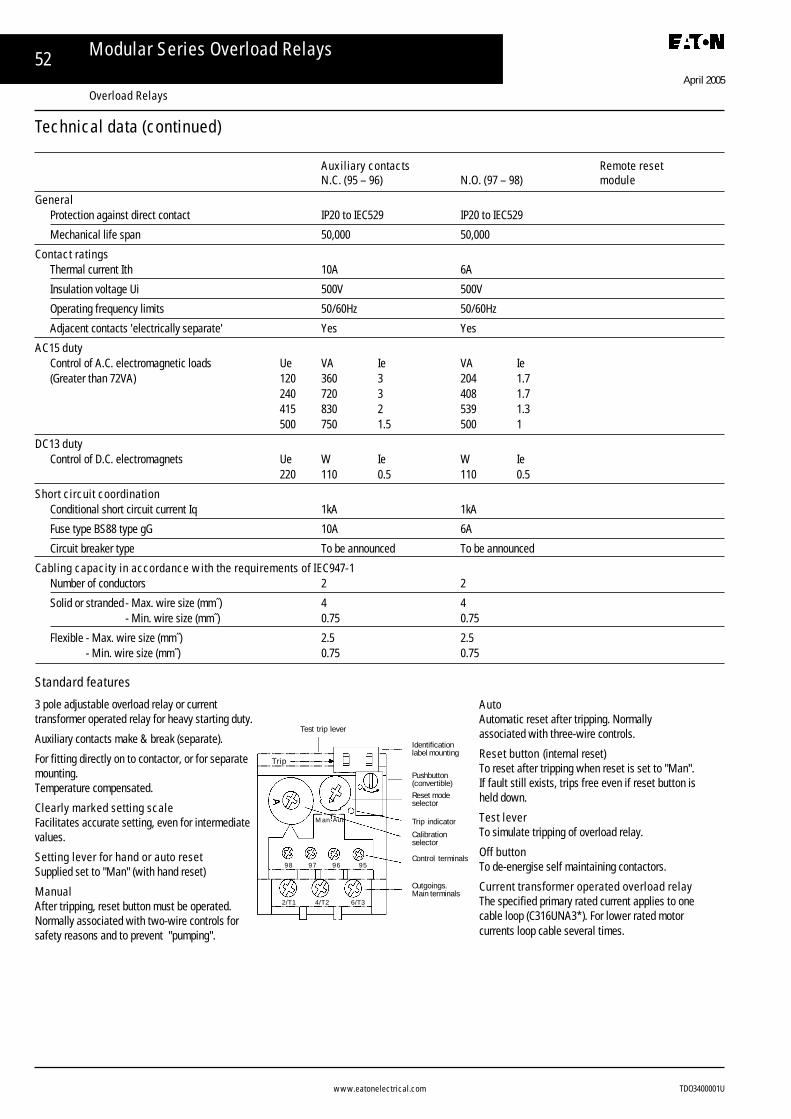
Auxiliary contactsN.C. (95 – 96) N.O. (97 – 98)
GeneralProtection against direct contact IP20 to IEC529 IP20 to IEC529
Mechanical life span 50,000 50,000
Contact ratingsThermal current Ith 10A 6A
Insulation voltage Ui 500V 500V
Operating frequency limits 50/60Hz 50/60Hz
Adjacent contacts 'electrically separate' Yes Yes
AC15 dutyControl of A.C. electromagnetic loads Ue VA Ie VA Ie(Greater than 72VA) 120 360 3 204 1.7
240 720 3 408 1.7415 830 2 539 1.3500 750 1.5 500 1
DC13 dutyControl of D.C. electromagnets Ue W Ie W Ie
220 110 0.5 110 0.5
Short circuit co-ordinationConditional short circuit current Iq 1kA 1kA
Fuse type BS88 type gG 10A 6A
Cabling capacity in accordance with the requirements of IEC947-1Number of conductors 2 2
Solid or stranded - Max. wire size (mm˝) 4 4- Min. wire size (mm˝) 0.75 0.75
Flexible - Max. wire size (mm˝) 2.5 2.5- Min. wire size (mm˝) 0.75 0.75
Standard features
Trip
Identificationlabel mounting
Pushbutton(convertible)Reset modeselector
Trip indicatorCalibrationselector
Outgoings.Main terminals
98 97 96 95
2/T1 4/T2 6/T3
Man Aut
Control terminals
Test trip lever
Remote reset moduleCircuit diagram
Cut-outcontact
Overloadrelay must beset in themanual resetmode
Commandcontact
Remotereset coil
Impulse duration0.2 to 0.3 secs.
L1 N L2
E1 E298O/L
97
Technical data
Freedom Series – 2.2 to 160kW
www.eatonelectrical.com
April 2005
TDO3400001U
32 Freedom Series Contactors and Overload Relays
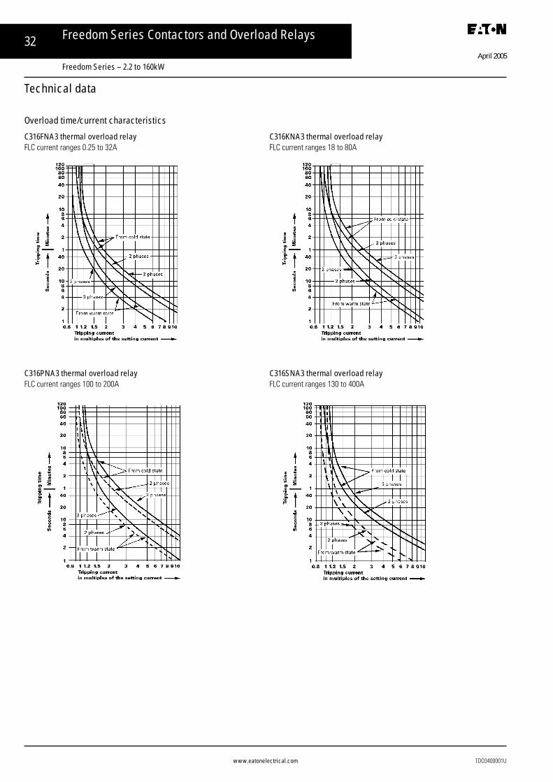
Overload time/current characteristics
C316FNA3 thermal overload relay C316KNA3 thermal overload relayFLC current ranges 0.25 to 32A FLC current ranges 18 to 80A
C316PNA3 thermal overload relay C316SNA3 thermal overload relayFLC current ranges 100 to 200A FLC current ranges 130 to 400A
Technical data
Freedom Series – 2.2 to 160kW

www.eatonelectrical.com
April 2005
TDO3400001U
33
ContactorsCE15AN to FN Mechanically interlocked contactors
CE15AN to FN contactor + C316FNA3 thermal C316FNA3 thermal overload relay and C306TB1 overload relaymounting adaptor
C316FNA3 thermal overload relay + C316RR1 remote reset module
Dimensions (mm)
Freedom Series Contactors and Overload Relays
Freedom Series – 2.2 to 160kW

www.eatonelectrical.com
April 2005
TDO3400001U
34
ContactorsCE15GN to KN Mechanically interlocked contactors
CE15GN to KN contactor + C316KNA3 thermal overload relay C316KNA3 thermal overload relay and C316TB1 overload relaymounting adaptor
Contactors Mechanically interlocked contactorsCE15LN to NN
Dimensions mm (continued)
Freedom Series Contactors and Overload Relays
Freedom Series – 2.2 to 160kW

www.eatonelectrical.com
April 2005
TDO3400001U
35Freedom Series Contactors and Overload Relays
ContactorsMCE15PN to SN Mechanically interlocked contactors
C316PNA3 thermal overload relay
CE15LN to NN contactor + CE16PNA3 thermal overload relay MCE15PN to SN contactor + C316PNA3 thermal overload relay(with links C316MCL) (with links C316PCL)
Freedom Series – 2.2 to 160kW
MCE15PN 236MCE15RN to SN 265

www.eatonelectrical.com
April 2005
TDO3400001U
36 Freedom Series Contactors and Overload Relays
C316SNA3 CT operated thermal overload relay
Contactors CE15AN to FN Contactors CE15LN to NN
Contactors CE15GN to KN Contactors MCE15PN to SN
XUe ≤460V 30
Ue >460V 55
X YUe ≤460V 1.5 14
Ue >460V 12 29
Dimensions mm (continued)
Contactor safety perimeter zones (mm)
Freedom Series – 2.2 to 160kW

www.eatonelectrical.com
April 2005
TDO3400001U
37Freedom Series Contactors and Overload Relays
This table is based on motors of approximately 1450 r.p.m. of averageefficiency and power factor. Motors of higher speed than 1450 r.p.m. usuallytake a lower current than that shown in the table; while motors of lowerspeed usually take higher current.
Wide variations from these figures can arise and engineers should, wheneverpossible, determine the actual FLC from the motor rating plate in each case.
Motor rating VoltagekW hp 220 380 415 500 550 660
0.37 0.5 2.1 1.2 1.1 0.9 0.8 0.70.55 0.75 2.8 1.6 1.5 1.2 1.1 0.90.75 1.0 3.5 2.0 1.9 1.5 1.4 1.2
1.1 1.5 4.9 2.9 2.6 2.2 2.0 1.61.5 2.0 6.3 3.6 3.3 2.8 2.5 2.12.2 3.0 9.0 5.2 4.8 4.0 3.6 3.0
3.0 4.0 12 6.8 6.2 5.1 4.7 3.94.0 5.5 16 9.1 8.3 6.9 6.3 5.25.5 7.5 21 12 11 9.4 8.5 7.1
7.5 10 27 16 14 12 11 9.110 13.5 36 21 19 16 14 1211 15 40 23 21 17 16 13
15 20 52 30 28 23 21 1718.5 25 64 37 34 28 26 2122 30 77 44 41 34 31 26
It is important to note that these figures are average values and thatactual values can vary by +20% –10% for motors up to 7.5kW and by±10% for motors above 7.5kW.
Motor rating VoltagekW hp 220 380 415 500 550 660
30 40 100 59 54 45 41 3437 50 125 73 67 55 50 4245 60 150 86 79 66 60 50
55 75 180 106 98 81 74 6175 100 240 140 130 105 96 8090 125 300 170 160 130 120 99
110 150 350 200 190 160 140 120132 175 410 240 220 180 160 140160 220 510 300 270 230 210 170
200 270 630 360 330 280 250 210220 300 730 420 380 320 290 240250 350 810 470 430 360 320 270
Starter Main/Delta Starter Ie Star contactor size(kW) contactor line current (A) Without mech interlock With mech interlock
5.5 CE15A 12 CE15A CE15A7.5 CE15B 16 CE15A CE15A11 CE15C 23 CE15B CE15B15 CE15D 30 CE15C CE15C18.5 CE15E 37 CE15D CE15D22 CE15F 44 CE15D CE15D
30 CE15G 59 CE15E CE15G37 CE15H 73 CE15F CE15G45 CE15J 86 CE15G CE15G55 CE15K 100 CE15G CE15G75 CE15L 140 CE15H CE15L90 CE15M 170 CE15K CE15L
110 CE15N 190 CE15L CE15N132 CE15N 240 CE15M CE15N160 MCE15R 300 CE15N CE15N200 MCE15R 360 CE15N CE15N250 MCE15S 470 MCE15P MCE15P
Ue = 380/415V Star delta starters
Notes:1. Main and delta contactors delta connected.2. Star contactor life 100,00 operations or greater at normal starting duty
(make 2 x Ie, break 1 x Ie).
3. Maximum starting time in the star connection 25 seconds.4. For heavy duty starting where the star contactor breaks >1 x Ie, or where
the starting time in the star connection is greater than 25 seconds, orwhere contactor life is insufficient, use the same size of contactor as formain and delta.
Three phase 50Hz motors approx. FLC at line voltage
Star-delta starters utilising smaller star contactor size
Freedom Series – 2.2 to 160kW

www.eatonelectrical.com
April 2005
TDO3400001U
38 Modular Series Contactors
ContactorsAC1 rating Number of poles Width Catalogue(A) N.O. N.C. (mm) number
30 4 – 45 GH15BN40*30 2 2 45 GH15BN22*30 – 4 45 GH15BN04*40 4 – 45 GH15DN40*
50 4 – 60 GH15FN40*63 4 – 60 GH15GN40*63 2 2 60 GH15GN22*63 – 4 60 GH15GN04*
80 4 – 70 GH15HN40*100 4 – 70 GH15JN40*
125 4 – 105 GH15LN40*125 2 2 105 GH15LN22*125 – 4 105 GH15LN04*
160 3 – 150 GH33B-3-22*
200 3 – 150 GH35B-3-22*
250 3 – 150 GH37B-3-22*
* Add suffix from the table to select coil operating voltage. For voltages not shown please contact Head Office.
Catalogue numbers

www.eatonelectrical.com
April 2005
TDO3400001U
39
ContactorsAC1 rating Number of poles* Width Catalogue(A) N.O. N.C. (mm) number
350 3 – 177 GH44-3-22*
450 3 – 214 GH52-3-22*
240 3 – 220 GH55-3-22*
280 3 – 220 GH57-3-22*
375 3 – 280 GH62-3-22*
475 3 – 280 GH64-3-22*
550 3 – 334 GH76-3-12*
650 3 – 334 GH78-3-12*
Modular Series Contactors
* Select add-on neutral switching pole, see page 41

www.eatonelectrical.com
April 2005
TDO3400001U
40
Operating coilsContactors GH76 to 78Dual frequency AC coils
Coil voltage Suffix50/60Hz code
110/120 A220/240 K380/415 M440/480 C
DC coils
48 W1120 A1220 B1
Contactors GH15 to GH55Combined dual frequency AC and DC coils
Coil voltage Suffix50/60Hz D.C. code
110/120 110 A220/240 200/220 K380/415 345/380 M440/480 400/440 C
Accessories
Contactor GH15BN GH15FN GH15LN GH33B GH44 GH52 GH55 GH62 GH76type GH15DN GH15HN GH35B GH57 GH64 GH78
GH15HN GH37B
Coil type B01– B02– B021– B31– B9– B7– B51– B61– B8–
Feeder / / / / / / FG51 FG61 FG78group type
Hz 50-60 50 60 50-60(1) 50-60 50 60 50 60 50 60 50-60 50-60 50-60
AC voltage V 24 24 24 24 24 24 24 24 24V 48 48 48 48 48 48 48 48 48V 110-120 110 110 110-120 110 110 110 110 110 110 110-120 110-120 110-115V 115 115 115 115V 220-240 22-230 220 220-240 220-230 220 220-230 220 220-230 220 220-240 220-240 220-230V 240 240 240 240 240 240 240 240 240V 380-415 380-400 380-415 380-400 380-400 380-400 380-415 380-415 380-400V 415 415 415 415V 440 440 440 440 440V 440-480 460 460 460 460 440-480 440-480V 480 480 480 480
DC voltage V 24 24 24 24 24 24 24 24V 48 48 48 48 48 48 48 48V 110 110 110 110 110 110 100-110 100-110 110V 220 220 220 220 220 220 200-220 200-220 220
EG B01–240 is a 240V coil for a GH15DN contactorWith these coils at 50Hz the comsumption is increaded by 25% and the mechanical durability is reduced by 50%
Standard available control voltages
Modular Series Contactors

www.eatonelectrical.com
April 2005
TDO3400001U
41
A.C. Operating coilCoil 50Hz 24 48 110 220 240 380 415 440 550voltage 60Hz – – 120 240 – – – 480 600
Suffix code U Y A B K L M C D
Auxiliary contact blocks - top mounting (max 1 per contactor)
Contact Catalogueconfiguration numbers
1 N.O. – C320KGT1– 1 N.C. C320KGT21 N.O. 1 N.C. C320KGT32 N.O. – C320KGT4– 2 N.C. C320KGT52 N.O. 2 N.C. C320KGT153 N.O. 1 N.C. C320KGT144 N.O. – C320KGT13
Pneumatic timer - top mounting
Description Cataloguenumbers
Adjustable range(On or off delay)
0.3 to 30 secs. C320TP110 to 180 secs. C320TP2
Note: When timer is used, other top mounting auxiliaries cannot be added.
Catalogue numbers – Accessories
Accessories Table
Description GH15BN, GH15DN, GH33B, GH35B, GH44 GH52 GH55 GH57 GH62 & 64 GH76 & 78GH15FN, GH15HN, GH37BGH15JN, GH15LN
Add on Aux control blocks1no GH15T01 - - - - - - -1nc GH15T10 - - - - - - -1no-1nc GH15T11 GH15T11-3 - - - - - EB111no-1nc Add on* - GH15T11-3A - - - - - -2no-2nc GH15T22 - EF22 EF22 EF22 EF22 EF22 -3no-1nc GH15T31 - - - - - - -4no GH15T40 - - - - - - -
Add on neautral Switching Pole125 (lth) - NP125-3 - - - - - -175 (lth) - - NP175-4 - - - - -250 (lth) - NP250-3 - - - - - -325 (lth) - - - NP325-5 NP325-5 NP325-5 - -350 (lth) - - NP350-3 - - - - -500 (lth) - - - NP500-3 NP500-5 NP500-5 NP500-6 -760 (lth) - - - - NP760-5 NP760-5 - -1000 (lth) - - - - - - NP1000-6 NP1000-7
Mechnical interlockHorizontal BMOH BM07 BM08 BM5H BM5H BM5H BM6H BM6HVertical - - BM09 BM5V BM5V BM5V BM6V BM7V
Mechanical Latch KitKit complete - - AM44 AM5-52 AM5 AM5 AM6 -
Three pole shroudsshrouds - PR37 PR44 PR55 PR55 PR57 PR62 PR64
Modular Series Contactors

www.eatonelectrical.com
April 2005
TDO3400001U
42
Technical data
Contactor GH15BN GH15DN GH15FN GH15HN GH15JN
GeneralkW AC3 rating 400V 4 7.5 15 22 30
Standards and approvals IEC 60947-4-1 IEC 60947-4-1 IEC 60947-4-1 IEC 60947-4-1 IEC 60947-4-1
Width mm 45 45 60 79
Number of poles (maximum) 4 4 4 4 4
Add on 4th pole N/A N/A N/A N/A N/A
Protection against direct contact IP20-IP10* IP20-IP10* IP20-IP10* IP20-IP10* IP20-IP10*
Mechanical lifespan 1,000,000 1,000,000 1,000,000 1,000,000 1,000,000
Weight kg 0.4 0.4 0.9 1.28 1.28
EnvironmentPollution degree 3 3 3 3 3
Operating temperature –25 to +55°C –25 to +55°C –25 to +55°C –25 to +55°C –25 to +55°C
Relative humidity at 40°C 92% 92% 92% 92% 92%
Operating altitude 2000m 2000m 2000m 2000m 2000m
Operating position (relative to normal mounting position) 90° 90° 90° 90° 90°
Main contact ratingsInsulating voltage 690V 690V 690V 690V 690V
Operating frequency limits Per Hour 3000 3000 3000 3000 3000
Rated thermal current Ith 30 40 50 80 100
AC1 Watts
230V 12 15 20 31 39
240V 12 16 20 33 41
400V 20 27 34 55 69
415V 21 28 235 57 71
440V 22 30 38 60 76
500V 25 34 43 69 86
690V 35 47 59 95 119
AC2/3 Watts
230V 2.2 4 7.5 12.5 18.5
240V 2.2 4 7.5 15 18.5
400V 4 7.5 15 22 30
415V 4.3 8 15 22 30
440V 4.7 9 16.5 25 33
500V 5.5 10 15 22 30
690V 5.5 7.5 15 22 30
AC2/3 IE
440V 9 16 32 50 63
500V 9 16 24 38 45
690V 7 9 18 26 34
AC4 Watts
230V 0.9 1.6 3 5.5 7.5
240V 1.5 3 5.5 11 15
400V 1.5 3 5.5 11 15
415V 1.5 3 5.5 11 15
440V 1.5 3 5.5 11 15
500V 1.5 3 5.5 11 15
AC4 IE
440V 4 7 12 23 30
Modular Series Contactors

www.eatonelectrical.com
April 2005
TDO3400001U
43
Technical data
Contactor GH15LN GH33B GH35B GH37B GH44 GH52
GeneralkW AC3 rating 400V 45 55 75 90 110 160
Standards and approvals IEC 60947-4-1 IEC 60947-4-1 IEC 60947-4-1 IEC 60947-4-1 IEC 60947-4-1 IEC 60947-4-1
Width mm 105 168 168 168 223 223
Number of poles (maximum) 4 3* 3* 3* 3* 3*
Add on 4th pole N/A NP125-3/NP250-3 NP125-3/NP250-3 NP125-3/NP250-3 NP175-4/NP350-4 NP325-5/NP500-5
Protection against direct contact IP20-IP10* IP00 IP00 IP00 IP00 IP00
Mechanical lifespan 1,000,000 1,000,000 1,000,000 1,000,000 800,000 500,000
Weight kg 2.2 5 5 5 7.3 12.8
EnvironmentPollution degree 3 3 3 3 3 3
Operating temperature –25 to +55°C –25 to +55°C –25 to +55°C –25 to +55°C –25 to +55°C –25 to +55°C
Relative humidity at 40°C 92% 92% 92% 92% 92% 92%
Operating altitude 2000m 2000m 2000m 2000m 2000m 2000m
Operating position (relative to normal mounting position) 90° 90° 90° 25° 25° 25°
Main contact ratingsInsulating voltage 690V 690V 690V 690V 690V 690V
Operating frequency limits Per Hour 3000 3000 3000 3000 3000 3000
Rated thermal current Ith 125 160 200 250 350 400
AC1 Watts
230V 49 63 79 99 139 179
240V 51 66 83 103 145 187
400V 86 110 138 173 242 311
415V 89 115 143 179 251 323
440V 95 121 152 190 266 342
500V 108 138 173 216 303 389
690V 149 191 239 298 418 537
AC2/3 Watts
230V 25 33 40 50 60 90
240V 25 33 45 55 65 100
400V 45 55 75 90 110 160
415V 47 59 80 95 115 180
440V 51 63 85 100 125 190
500V 51 55 75 100 132 210
690V 51 55 75 110 132 210
AC2/3 IE
440V 95 115 150 175 210 315
500V 80 85 110 145 210 315
690V 60 70 85 120 150 240
AC4 Watts
230V 11 12 15 18.5 25 37
240V 18.5 22 25 30 45 63
400V 18.5 22 25 33 45 65
415V 22 25 30 34 48 67
440V 22 22 25 30 55 75
500V 22 22 25 30 55 75
AC4 IE
440V 40 45 55 63 120
Modular Series Contactors

www.eatonelectrical.com
April 2005
TDO3400001U
44
Electrical and Mechanical Ratings for Contactors to IEC 60947-1Operating conditions:Cooling air temperature surrounding contactor = –20°C to +55°CMaximum altitude = 2000m.A.C. ratings are 3 phase 50–60Hz for main contacts.
Contactor GH55 GH57 GH62Insulation voltage Ui 1000 1000 1000Thermal current (Ith open) 600 760 1000
kW kW kW
AC1 Non-inductive or slightly inductive 220/240V 185 230 306(2) loads P.F. = 0.95 380V 315 400 527
Ratings are for open contactors at 415/440V 365 465 612ambient temperatures ≤ 55°C 500/550V 420 530 697
660V 550 730 9181000V 835 1060 1360
kW leA kW leA kW IeA
AC2 Slipring motors starting and plugging 220/240V 129 450 160 550 220 700380V 220 450 280 550 375 700
AC3 Squirrel cage motors starting and 415/440V 240 450 315 550 400 700F.L.C. breaking 500/550V 300 420 375 520 500 630
660V 335 350 450 450 600 6301000V 280 170 355 260 500 350
AC4 Squirrel cage motor starting, 220/240V 45 180 51 200 68 220inching, plugging. 380V 75 180 90 200 120 220Stopping during run up 415/440V 80 180 100 200 132 220
500/550V 100 140 110 145 150 150660V 100 140 110 145 150 150
Maximum number of operations per hour at above ratings AC2/AC3 – AC4 duty 300 – 100 300 – 100 300 – 100
Other kW IL kW IL kW IL
Star delta starter 220V 220 700 270 900 300 1100(Delta loop connected) 380V 335 700 450 900 600 1100
415/440V 400 700 500 900 650 1100500/550V 400 650 500 800 700 900660V 450 550 600 650 800 850
Rotor contactors Intermediate (1) A 1000 1300 1600(Delta connected) Final A 700 900 1100
Transformer primary switching 440V A 180 220 300
Tungsten or infra-red lamps 250V A 260 315 440
Mercury vapour lamps 440V A 400 500 650
Non-compensated fluorescent lamps 440V A 360 450 570Compensated fluorescent and sodium vapour lamps 440V A 300 360 460
Capacitor switching 380V 3ph kVAr 200 250 350(Single bank only)
General Average operating times Pick up ms 100 100 105data (AC coil) Drop out ms 170 170 200
AC coil consumption Pick up – Seal VA 950 – 11 950 - 11 1600 - 25Seal Watts 10 10 22
Mechanical endurance Millions of operations 5 5 5
(1) Ratings apply when intermediate contactors are shorted out by final contactor and have an on-load time ≤ 15 secs.(2) When contactors are operated continuously at maximum AC1 ratings excessive terminal temperature rises can occur due to oxidation of terminals and/or contaminationof contacts. It is recommended that plated or oxidation protected external connections are used.Note: leA figures given are contactor maximum amperes.
ratings
Technical data (continued)
Modular Series Contactors

www.eatonelectrical.com
April 2005
TDO3400001U
45
GH64 GH76 GH781000 660 6601100 1200 1350kW kW kW
335 365 415580 635 715670 735 830765 835 9451000 1100 12451525 – –
kW leA kW leA kW leA
270 860 320 1000 380 1200475 860 550 1000 650 1200500 860 600 1000 700 1200600 760 720 1000 840 1200650 680 930 1000 1120 1200550 380 – – – –
80 240 110 370 132 400150 240 185 370 220 400160 240 200 370 230 400180 160 240 300 250 350180 160 240 250 275 285
300 – 100 120 – 30 120 – 30
kW IL kW IL kW IL
400 1300 450 1500 – –700 1300 850 1500 950 –750 1300 900 1500 – –850 1000 1000 1100 1100 –900 1000 1200 1100 1400 –
2000 2500 30001300 1500 1700
350 400 500
500 560 630
800 950 1100
700 850 1000500 660 800
400 450 500
105 70 70200 50 50
1600 – 25 2450 – 75 2450 – 7522 60 60
5 1 1
Modular Series Contactors

www.eatonelectrical.com
April 2005
TDO3400001U
46
Technical data (continued)
Auxiliary C320TP2 GH15S11 GH15S11-3 GH15S11-3A* EF22 EB11TypeTop mount Aux Side mount Aux Side mount Aux Side mount Aux Side mount Aux Side mount AuxContacts 1 N/O – 1 N/C 1 N/O – 1 N/C 1 N/O – 1 N/C 1 N/O – 1 N/C 2 N/O – 2 N/C 1 N/O – 1 N/CTime delay 10-180 SEC - - - - -Weight kg 0.08 0.05 0.08 0.08 0.12 0.17Ui 690 690 690 690 690 690ith A 10 10 10 10 16 16Short time withstand 500ms 60A 500ms 60A 500ms 60A 500ms 60A 500ms 60A 500ms 60AProtection fuse 10 A gG 10 A gG 10 A gG 10 A gG 10 A gG 10 A gGAC15
120V 4 6 6 6 6 6240V 2.5 3 3 3 3 3400V 2 2 2 2 2 2500V 1.5 1.5 1.5 1.5 1.5 1.5690V 1 1 1 1 1 1
DC1324V - 4 4 4 6 648V 1 1.5 1.5 1.5 3 3110V 0.6 0.5 0.5 0.5 1 1220V 0.3 0.2 0.2 0.2 0.5 0.5
Auxiliary GH15T01 GH15T10 GH15T11 GH15T22 GH15T31 GH15T40 C320TP1TypeTop mount Aux Top mount Aux Top mount Aux Top mount Aux Top mount Aux Top mount Aux Top mount Aux Top mount AuxContacts 1 N/C 1 N/O 1 N/O – 1 N/C 2 N/O – 2 N/C 3 N/O – 1 N/C 4 N/O 1 N/O – 1 N/CTime delay - - - - - - 0.3 – 30SECWeight kg 0.011 0.011 0.05 0.05 0.05 0.05 0.08Ui 690 690 690 690 690 690 690ith A 10 10 10 10 10 10 10Short time withstand 500ms 60A 500ms 60A 500ms 60A 500ms 60A 500ms 60A 500ms 60A 500ms 60AProtection fuse 10 A gG 10 A gG 10 A gG 10 A gG 10 A gG 10 A gG 10 A gGAC15
120V 6 6 6 6 6 6 4240V 3 3 3 3 3 3 2.5400V 2 2 2 2 2 2 2500V 1.5 1.5 1.5 1.5 1.5 1.5 1.5690V 1 1 1 1 1 1 1
DC1324V 5 5 5 5 5 5 -48V 2 2 2 2 2 2 -110V 0.8 0.8 0.8 0.8 0.8 0.8 0.6220V 0.4 0.4 0.4 0.4 0.4 0.4 0.3
Modular Series Contactors

www.eatonelectrical.com
April 2005
TDO3400001U
47
Sizes GH15BN & DNDimensions (mm)
Sizes GH15GN, HN & JN
Modular Series Contactors
Four-pole contactors - AC coil
GH15FNGH15GN
GH15HNGH15JN
GH15LN

www.eatonelectrical.com
April 2005
TDO3400001U
48
Three/Four-pole Contactors - AC coil
Contactor Dimension Mechanical intlk. WeightA B C D E F G H J K L mounting matrix (kg)
Horiz Vert
GH55 220 233 225 110 220 160 72 8 30 10.5 80 262 314 13GH57 220 258 225 110 220 160 72 8 40 12.5 80 262 314 13.5GH62 280 307 291 175 280 200 90 10 50 13 100 312 380 26GH64 280 361 291 175 280 200 90 10 50 15 100 312 380 28GH76 334 490 345 120 380 220 111 12 50 17 x 2 100 380 580 49GH78 334 490 345 120 380 220 111 12 60 17 x 2 100 380 580 53
Three-pole contactors - AC coil
DC coil
Modular Series Contactors

www.eatonelectrical.com
April 2005
TDO3400001U
49Modular Series Overload Relays
Catalogue numbers
Overload Relays
➀ Relay with 1N.O. – 1N.C. electrically separate contacts, selectable hand or auto reset with reset or stop-reset option, phase loss protection and trip indicator.
For direct connection with CE15AN to FN contactors or independent mountingDescription Motor FLC range A Catalogue numbers
Relay with 1 N.O. – 1 N.C. electrically separate contacts, 0.25 – 0.4 C316FNA3Cselectable hand or auto reset with reset or stop-reset option, 0.4 – 0.63 C316FNA3Dphase loss protection and trip indicator. 0.63 – 1.0 C316FNA3E
1.0 – 1.4 C316FNA3F1.3 – 1.8 C316FNA3G1.7 – 2.4 C316FNA3H2.2 – 3.1 C316FNA3J2.8 – 4.0 C316FNA3K3.5 – 5.0 C316FNA3L4.5 – 6.5 C316FNA3M6.0 – 8.5 C316FNA3N7.5 – 11.0 C316FNA3P10 – 14.0 C316FNA3Q13 – 19.0 C316FNA3R18 – 24.0 C316FNA3S24 – 32.0 C316FNA3T
Separate base for independent connectionand DIN rail or panel mounting C306TB1
Thermal overload relays for independent mounting and connection with GH33 & GH37 contactors.➀
65 – 90 C316PNA3A80 – 110 C316PNA3B100 – 135 C316PNA3C110 – 150 C316PNA3D130 – 175 C316PNA3E150 – 200 C316PNA3F
Thermal overload relays, current transformer operated, for independent connection with GH44 contactors.➀
130 – 185 C316SNA3A165 – 235 C316SNA3B220 – 310 C316SNA3C285 – 400 C316SNA3D
Identification marker (pack of 50) C316MT1
Thermal overload relays, current transformer operated, for independent connection to GH55 to 78 contactors.➀
355 – 500 C316UNA3A465 – 650 C316UNA3B610 – 850 C316UNA3C
Remote reset module
Description Operating voltage 50/60HZ Catalogue number
For use with thermal 220/440 C316RR1Noverload relays C316SNA3and C316UNA3

www.eatonelectrical.com
April 2005
TDO3400001U
50 Modular Series Overload Relays
Electrical life
The two graphs below show average contact life for AC3 and AC4 dutiesrespectively.To obtain the contact life for duties which include a proportion of both AC3and AC4 operations the following may be used.
N = AC3 life Z = % AC4 operationsP = AC4 life S = % AC3 operations
N.PZ.N. + S.P
where
Auxiliary contactsSpecifications
IEC337-1, BS4774-1Maximum number
4 N.O. - 4 N.C.Thermal rating
25A
Contact ratings AC11
Rated operational Rated operationalvoltage UeV current IeA
120 14240 7440 4600 2
Contact rating DC11
Rated operational Rated operationalvoltage dc current IeA
24 1848 15110 7220 4
Terminal capacitySolid or stranded: 2 x 4mm˝
Contact life =
Technical data
Terminal markings
Select AC3 and AC4 life for operational current required from graphs below. Estimate number of AC4 operations in percent and calculate from above equation.
Overload Relays

www.eatonelectrical.com
April 2005
TDO3400001U
51Modular Series Overload Relays
Overload relays C316PNA3 C316SNA3 C316UNA3General
Thermal current Ith Up to 200A Up to 400A Up to 850ACT operated CT operated
Standards and approvals IEC 947-4-1, IEC 292-1, BS4941, VDE0660, UL 508, CSA C22-14, NFC 63-650Trip class IEC947-4-1 10A 30 30Terminal marking EN50005 (BS5472)Width (mm) 80* 193 246
* Width across terminals is greater, <100A = 85mm, >100A = 105mmProtection against direct contact Protected against unintentional contact in accordance with VDE0106 pt 100Weight (kg) 0.91 1.5 3
EnvironmentPollution degree IEC947-1 3 3 3Impulse withstand voltage IEC947-4-1 6kV 6kV 6kVOperating temperature, open –25 to +55°C –25 to +55°C –25 to +55°CTemperature compensation range –25 to +50°C –25 to +50°C –25 to +50°CMaximum altitude 2000m 2000m 2000mOperating position (relative to normal position) ±30° ±30° ±30°Climatic conditions Damp heat constant to IEC68-2-3. Damp heat, cyclic to IEC68-2-30Mechanical shock resistance 12g for 15ms 12g for 15ms 12g for 15msVibration @ 45Hz 8g (1mm displacement with N.C. contacts maintained)Storage temperature –40 to +70°C –40 to +70°C –40 to +70°C
Main contactsInsulation voltage Ui 690V 690V 690VCurrent range 100 – 200A 130 – 400A 265 – 850APower dissipatedat minimum setting 5.8W 2.2W 2.2Wat maximum setting 7.3W 3.3W 3.3WMax operating frequency of motor (starts per hour) 15 (dependent upon starting time and current)Short circuit co-ordination Type 2 to IEC947-4-1Rated conditional short circuit current 50kA 50kA 50kAFuse type See table on page 46
Cabling capacity in accordance with the requirements of IEC947-1Cabling capacity using compression lugs (mm˝) 25 to 120 – –Terminal flag bolt size - <100A M6 – –
- >100A M10 – –CT aperture size (mm) – 22 x 28 45 x 22
Technical data
Overload Relays
www.eatonelectrical.com
April 2005
TDO3400001U
52 Modular Series Overload Relays
Auxiliary contacts Remote resetN.C. (95 – 96) N.O. (97 – 98) module
GeneralProtection against direct contact IP20 to IEC529 IP20 to IEC529Mechanical life span 50,000 50,000
Contact ratingsThermal current Ith 10A 6AInsulation voltage Ui 500V 500VOperating frequency limits 50/60Hz 50/60HzAdjacent contacts 'electrically separate' Yes Yes
AC15 dutyControl of A.C. electromagnetic loads Ue VA Ie VA Ie(Greater than 72VA) 120 360 3 204 1.7
240 720 3 408 1.7415 830 2 539 1.3500 750 1.5 500 1
DC13 dutyControl of D.C. electromagnets Ue W Ie W Ie
220 110 0.5 110 0.5Short circuit coordination
Conditional short circuit current Iq 1kA 1kAFuse type BS88 type gG 10A 6ACircuit breaker type To be announced To be announced
Cabling capacity in accordance with the requirements of IEC947-1Number of conductors 2 2Solid or stranded - Max. wire size (mm˝) 4 4
- Min. wire size (mm˝) 0.75 0.75Flexible - Max. wire size (mm˝) 2.5 2.5
- Min. wire size (mm˝) 0.75 0.75
AutoAutomatic reset after tripping. Normallyassociated with three-wire controls.Reset button (internal reset)To reset after tripping when reset is set to "Man".If fault still exists, trips free even if reset button isheld down.Test leverTo simulate tripping of overload relay.Off buttonTo de-energise self maintaining contactors.Current transformer operated overload relayThe specified primary rated current applies to onecable loop (C316UNA3*). For lower rated motorcurrents loop cable several times.
Standard features3 pole adjustable overload relay or currenttransformer operated relay for heavy starting duty.Auxiliary contacts make & break (separate).For fitting directly on to contactor, or for separatemounting.Temperature compensated.Clearly marked setting scaleFacilitates accurate setting, even for intermediatevalues.Setting lever for hand or auto resetSupplied set to "Man" (with hand reset)ManualAfter tripping, reset button must be operated.Normally associated with two-wire controls forsafety reasons and to prevent "pumping".
Trip
Identificationlabel mounting
Pushbutton(convertible)Reset modeselector
Trip indicatorCalibrationselector
Outgoings.Main terminals
Control terminals98 97 96 95
2/T1 4/T2 6/T3
Test trip lever
AutMan
Technical data (continued)
Overload Relays

www.eatonelectrical.com
April 2005
TDO3400001U
53Modular Series Overload Relays
Recommended fuse sizes for type 2 co-ordinationCatalogue Motor full load current BS88 gG/gM DIN type gL/gi DIN type aM
number range (A) (A) (A) (A)C316PNA3A 65 – 90 200 200 160C316PNA3B 80 – 100 200 224 200C316PNA3C 100 – 135 200 224 200C316PNA3D 110 – 150 250 250 224C316PNA3E 130 – 175 315 315 250C316PNA3F 150 – 200 315 315 250
C316SNA3A 130 – 185 355 355 –C316SNA3B 165 – 235 450 400 –C316SNA3C 220 – 310 630 500 –C316SNA3D 285 – 400 750 630 –
C316UNA3A 265 – 375 500 800 –C316UNA3B 355 – 500 750 1000 –C316UNA3C 465 – 650 1000 1250 –C316UNA3D 610 – 850 1250 1250 –
C316UNA3 thermal overload relayFLC current ranges 265 to 850A
10000
5000
1.06 1.21.126
1000
500
120100
50
10
5
2
1
0.8Multiples of full load current
1.5 54 67.2
108 20
Cold Top line: 3 phaseBottom line: 2 phase
Hot Top line: 3 phaseBottom line: 2 phase
Trip time(secs)
0.7 1 2 3
Overload time/ Current characteristicsC316PNA3 thermal overload relay C316SNA3 thermal overload relayFLC current ranges 100 to 200A FLC current ranges 130 to 400A
10000
5000
1.06 1.21.126
1000
120100
50
10
1
0.8Multiples of full load current
1.5 20
Cold Top line: 3 phaseBottom line: 2 phase
Hot Top line: 3 phaseBottom line: 2 phase
Trip time(secs)
500
5
2
0.7 1 2 3 54 67.2
8 10
10000
5000
1.06 1.21.126
1000
120100
50
10
1
0.8Multiples of full load current
1.5 20
Cold Top line: 3 phaseBottom line: 2 phase
Hot Top line: 3 phaseBottom line: 2 phase
Trip time(secs)
500
5
2
0.7 1 2 3 54 67.2
8 10
Technical data (continued)
Overload Relays

www.eatonelectrical.com
April 2005
TDO3400001U
54 Modular Series Overload Relays
C316UNA3 thermal overload relaysApprovals and standards
IEC947-4 class 10A relay with single phase detectionIEC337, BS4941, VDE0660, CSA, UL
Electrical ratingsInsulation voltage Ui: 660 Volts AC
Climatic conditionsMaximum altitude: 2000 metresAmbient temperature compensation range: –25°C to +55°CStorage temperature range: –40°C to +70°CRelative humidity: 95% RH at 40°C DIN50017
Control contact ratings1N.O. – 1N.C. electrically separate
Typical trip characteristics
Co-ordination with short circuit protection devices
Catalogue Ratings of fuses for type 2 coordinationnumber BS88 class Q1 VDE0660 gl
C316UNA3A 450A 500AC316UNA3B 630A 800AC316UNA3C 710A 1000AC316UNA3A 1000A 1250A
Thermal overload relay
Reset functionSelectable: Automatic, manual or manual/stop
Reset time<5 minutes
Terminal capacitiesTerminals nos. 95 to 98: 2 x 2.5 or 2 x 4
Terminal markings
245
22
83 83
44
20345
4.5 Reset
Rating N.C. 95-96 N.O. 97-98
Thermal current Ith 10A 6ARated operational current Ie
at AC15 220V 3A 1.7A380V 2A 1.3A500V 1.5A 1A
Maximum fuse size 10A 6A
Technical data (continued)
Dimensions (mm)
Overload Relays

© 2005 Eaton Electric LimitedAll rights reserved
Printed in UKForm No TDO3400001UApril 2005
Eaton Electric LimitedReddings LaneBirmingham B11 3EZUnited Kingdom
Customer Support CentreTel: +44 (0)8700 545 333Fax: +44 (0)8700 540 333email: [email protected]
Eaton Electric NV PO Box 23 7550 AA Hengelo The Netherlands
Customer Support CentreTel: +31 (0)74 246 7066Fax: +31 (0)74 246 7070email: [email protected]
Eaton’s Electrical business is a global leader in electrical control, powerdistribution, and industrial automation products and services. Throughadvanced product development, world-class manufacturing methods, and global engineering services and support, Eaton’s Electrical businessprovides customer-driven solutions under brand names such as Cutler-Hammer® , Durant® , Heinemann® , Holec® and MEM® , whichglobally serve the changing needs of the industrial, utility, lightcommercial, residential, and OEM markets. For more information, visitwww.EatonElectrical.com.
Eaton Corporation is a diversified industrial manufacturer with 2004 salesof $9.8 billion. Eaton is a global leader in fluid power systems andservices for industrial, mobile and aircraft equipment; electrical systemsand components for power quality, distribution and control; automotiveengine air management systems and powertrain controls for fueleconomy; and intelligent drivetrain systems for fuel economy and safetyin trucks. Eaton has 55,000 employees and sells products to customers inmore than 125 countries. For more information, visit www.eaton.com.
www.eatonelectrical.com