iec 61076-4-101 definition of terms - farnell element14 · iec 61076-4-101 definition of terms ......
TRANSCRIPT

ept GmbH & Co. KG • Phone 0 88 61/25 01-0 • Fax 0 88 61/55 07 • E-Mail [email protected] • http://www.ept.de2.2
2.0 Connector System
IEC 61076-4-101
Definition of Terms
Connector according to IEC 61076-4-101
The hardmetric connector system ept-hm 2.0 was developed
according to the international standard IEC 61076-4-101. As a
result, a worldwide standard for the combination of PCBs is
safeguarded by multicontact plug-and-socket connectors for
customers.
PCBs can be exchanged without problems from system to system.
Important parameters like fixing, shielding and coding remain
compatible to all applications.
The spacing
The ept-hm 2.0 connectors have been developed with a spacing
of 2 mm between contacts. These connectors are modular and
therefore can be stacked together without interrupting the
continuity of the 2 mm design. No space is wasted within a row of
connectors.
Module stacking
To improve stacking and to avoid accidental reversal of
connectors the end of the housings engage the adjacent
connector to insure exact positioning onto the PCB board and
give the modules the necessary support.
Coding
In order to avoid accidental plug in among PC boards the IEC
61076-4-101 standard provides protection through coding. Coding
keys are easily hand inserted into the multifunction block of the
connector module A, L and M. The pins are color coded for fast
visual recognition.
Multifunction block
The modules A, L, M and compact PCI are equipped with a
multifunction block. The coding devices, according to the IEC
standard, can be added to the multifunction block. The guides
guaranty the correct mating and prohibit accidental reversal of
the male and fermale connectors.
That coding devices may be assembled by a single plug and
pulling tool and/or again removed.
Contact length of the rear and front mating area
ept offers 3 different lengths for the front mating area and 4 lengths
for the rear mating area for the hm 2.0 male connectors. Different
contact lengths are required for signal and ground contacts to
establish first make and last break features.
The long contacts with 11,25 mm are predominantly used for the
shielding rows z and f.
Thru hole specification of the PCB
Throughplated holes for signal contacts and shieldings in press-fit
techniques.
Derating Diagram
1
0,5
1,5
2
2,5
3
3,5
20 40 60 80 100 120 140 C
A
Ambient Temperature [ C]
Oper
atin
g Cu
rrent
[A]
loaded like a chess board
every 2nd row loaded
fully loaded
ØeloH mm6,0
elohllirD mm27,0-86,0
uC mµ52.nim
nS mµ51-5
hguorhtdetalPeloh
mm56,0-55,0

ept GmbH & Co. KG • Phone 0 88 61/25 01-0 • Fax 0 88 61/55 07 • E-Mail [email protected] • http://www.ept.de 2.3
2.0 Connector System
IEC 61076-4-101
Technical Notes
atadlacinahcemdnalacirtcelE
gnicapS mm2
egnarerutarepmeT C°521+sibC°55-
ytilibarudlacinahceM selcyCgnitaM052>
gnisuoH 0-V49LU.ccadellifssalGretseyloP
5-215CEIot.ccaecnatsisertcatnoC m02.xam Ω
lairetamtcatnoCtcatnocelaM eznorB
tcatnocelameF eznorB
ecafrustcatnocelamefdnaelaM iNrevoiNdPrevouA
ecnatsisernoitalusnI5-215CEI.cca
tcatnoC/tcatnoC 01.nim 4 MΩ
dleihS/tcatnoC 01.nim 4 MΩ
niprepecrofnoitresnItcatnoC N57,0.xam
dleihS N1.xam
niprepecrofnoitcartxEtcatnoC N51,0.nim
dleihS N51,0.nim
egatlovtseT
dedaolylluf noitisopdn2yreve draobssehC
e,c,awoRd,bwoR
wornihtiw V057 ffe V0051 ffe --
sworneewteb V0051 ffe V0051 ffe --
c,b,awoRd,c,b,awoR
e,d,c,b,awoR
wornihtiw V057 ffe V0051 ffe V0051 ffe
sworneewteb V057 ffe V057 ffe V0021 ffe
spagriadna-egapeerC
dedaolylluf notisopdn2yreve draobssehC
rotcennocelaMseludoM
rotcennocelameFelaMenalpkcaB
rotcennocelameFseludoM
rotcennocelaMenalpkcaB
rotcennocelameFseludoM
rotcennoc
e,c,awoRd,bwoR
wornihtiw mm8,0 mm6,0 mm5,2 mm5,2 -- --
sworneewteb mm5,2 mm5,2 mm5,2 mm5,2 -- --
c,b,awoRd,c,b,awoR
e,d,c,b,awoR
wornihtiw mm8,0 mm6,0 mm5,2 mm5,2 mm5,2 mm5,2
sworneewteb mm8,0 mm6,0 mm8,0 mm6,0 mm5,1 mm2,1

ept GmbH & Co. KG • Phone 0 88 61/25 01-0 • Fax 0 88 61/55 07 • E-Mail [email protected] • http://www.ept.de2.4
2.0 Connector System
IEC 61076-4-101
25 75 125 175 225 275 325 375 425 47536
44
52
60
68
76
84
92
100
108
116
Time [psec]
116 383
Change of impedance along the pin of row dof the ept connector hm2.0
Impedance after the elimination of multiplereflections, after impedance peeling.
male part Solder joint
Z [Ohm]
Connector
(Pin length of Row d = 22.5 mm)
Female part
Solder joint
14%
13%
9%
1%
0%0%
5%
10%
15%
0 200 400 600 800 1000trise [psec]
U[%
]re
flect
_max
U = f(trise)reflect_max
U is the maximum voltage reflected from theconnector in percent. U is plotted as a function of thesignal rise time. The connector is the only electricaldiscontinuity in a chosen 50Ohm System.
reflect_max
reflect_max
Electrical Characteristics
The connector system ept hm 2.0 was specially designed for
high data rates. Below are a few examples of the HF
characteristics.
A spice model is available for simulations during system design.
The simulation model was verified with TDR measurements.

ept GmbH & Co. KG • Phone 0 88 61/25 01-0 • Fax 0 88 61/55 07 • E-Mail [email protected] • http://www.ept.de 2.5
2.0 Connector System
IEC 61076-4-101
0 200 400 600 800 1000 1200 1400 1600 1800 2000
-0.012
-0.006
0
0.006
0.012
0.018
0.024
0.030Ucoupling [V]
Time [psec]
Crosstalk of a row d pin into an
adjacent row d pin (from C to G)
Measured Ucoupling, near end coupling
Measured Ucoupling, far end coupling
Basic signal noise
Simulated Ucoupling, near end coupling
Simulated Ucoupling, far end coupling
Near End Coupling
Far End Coupling
0 200 400 600 800 1000 1200 1400 1600 1800 20000.013
0.0110.0090.0070.0050.0030.001
0.0010.0030.0050.0070.0090.011
Time [psec]
Ucoupling [V]
Crosstalk of a pin in row d pin
to an adjacent row e pin.
(From C to A or E)
Measured Ucoupling, near end coupling
Measured Ucoupling, far end coupling
Simulated Ucoupling, near end coupling
Simulated Ucoupling, far end coupling
Basic signal noise
Near End Coupling
Far End Coupling
D0
edcb
B
C
A
D
E
G
Coupling (Cross talk)
The near end and far end coupling was measured and
simulated for different arrangements. A 200 mV signal with a rise
time of 25 psec was used.

ept GmbH & Co. KG • Phone 0 88 61/25 01-0 • Fax 0 88 61/55 07 • E-Mail [email protected] • http://www.ept.de2.6
2.0 Connector System
IEC 61076-4-101
A A A M A L A A
A A B A B B
AA A A
A
B
A
A
B
A
A
L
A
C
N
C
0
25
50
75
100
125
150
175
200
225
250
275
300
325
350
375
400
*
**
*
**
B B B
* total length for Europa cards** total length for ETSI PCB`s
System modularity
ept-hm 2.0 modules offer a great versatility to optimize large contact
densities. Especially the combination with coaxial or fiberoptic
connections.
Stacking can be arranged from 50 mm using type A module, increasing
in 25 mm steps to required lengths.
Connectors with multifunction block (type A, M, L) are preferably used
at the top of any column. Type B is only used between other modules.
The modules type C and N (25 mm) are polarized and are used at the
bottom end of the columns.
Correct mating is assured by use of coding keys within the multifunction
block and by use of type C and N modules.

ept GmbH & Co. KG • Phone 0 88 61/25 01-0 • Fax 0 88 61/55 07 • E-Mail [email protected] • http://www.ept.de 2.7
2.0 Connector System
IEC 61076-4-101
A
B
C
K
L
M
N
P
Q
R
S
T
Dimensions of Contacts Contact Options Front mating Used for
without mating area
signal contact
signal contact
8,25–0,1
9,75–0,1
11,25–0,1 shielding
with mating area13 mm
with mating area14,5 mm
with mating area16 mm
signal contact
signal contact
shielding
signal contact
signal contact
shielding
signal contact
signal contact
shielding
8,25–0,1
9,75–0,1
11,25–0,1
8,25–0,1
9,75–0,1
11,25–0,1
8,25–0,1
9,75–0,1
11,25–0,1
ept GmbH & Co. KG • Phone 0 88 61/25 01-0 • Fax 0 88 61/55 07 • E-Mail [email protected] • http://www.ept.de2.8
2.0 Connector System
IEC 61076-4-101
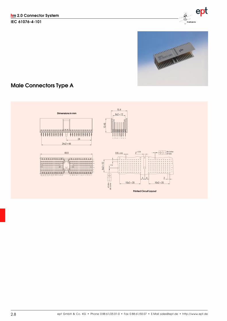
Male Connectors Type A
Printed Circuit Layout
Dimensions in mm
ept GmbH & Co. KG • Phone 0 88 61/25 01-0 • Fax 0 88 61/55 07 • E-Mail [email protected] • http://www.ept.de 2.9
2.0 Connector System
IEC 61076-4-101
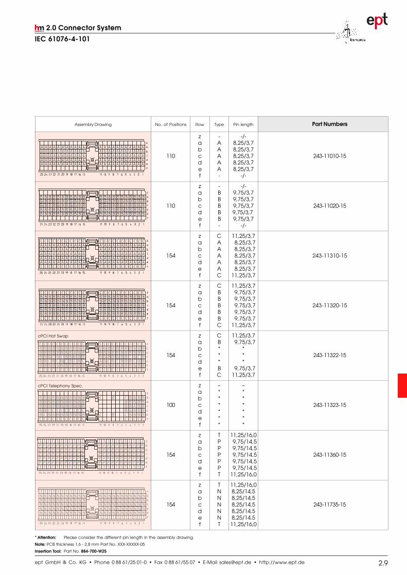
* Attention: Please consider the different pin length in the assembly drawing.
Note: PCB thickness 1,6 - 2,8 mm Part No. XXX-XXXXX-05
Insertion Tool: Part No. 884-700-W25
Assembly Drawing No. of Positions Row Type Pin length Part Numbers
z - -/-a A 8,25/3,7b A 8,25/3,7
110 c A 8,25/3,7 243-11010-15d A 8,25/3,7e A 8,25/3,7f - -/-
z - -/-a B 9,75/3,7b B 9,75/3,7
110 c B 9,75/3,7 243-11020-15d B 9,75/3,7e B 9,75/3,7f - -/-
z C 11,25/3,7a A 8,25/3,7b A 8,25/3,7
154 c A 8,25/3,7 243-11310-15d A 8,25/3,7e A 8,25/3,7f C 11,25/3,7
z C 11,25/3,7a B 9,75/3,7b B 9,75/3,7
154 c B 9,75/3,7 243-11320-15d B 9,75/3,7e B 9,75/3,7f C 11,25/3,7
cPCI Hot Swap z C 11,25/3,7a B 9,75/3,7b * *
154 c * * 243-11322-15d * *e B 9,75/3,7f C 11,25/3,7
cPCI Telephony Spec. z – –a * *b * *
100 c * * 243-11323-15d * *e * *f * *
z T 11,25/16,0a P 9,75/14,5b P 9,75/14,5
154 c P 9,75/14,5 243-11360-15d P 9,75/14,5e P 9,75/14,5f T 11,25/16,0
z T 11,25/16,0a N 8,25/14,5b N 8,25/14,5
154 c N 8,25/14,5 243-11735-15d N 8,25/14,5e N 8,25/14,5f T 11,25/16,0
26 ept Guglhör Peiting GmbH&Co. • Phone 0 88 61/25 01-0 • Fax 0 88 61/55 07 • E-Mail [email protected] • http://www.ept.de
2.0 Connector System
IEC 61076-4-101
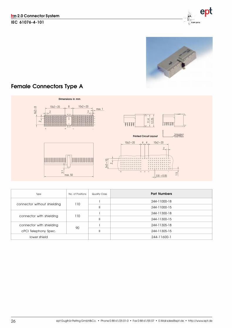
Female Connectors Type A
Dimensions in mm
Printed Circuit Layout
Type No. of Positions Quality Class Part Numbers
connector without shielding 110I 244-11000-18
II 244-11000-15
connector with shielding 110I 244-11300-18
II 244-11300-15
connector with shielding90
I 244-11305-18
cPCI Telephony Spec. II 244-11305-15
lower shield 244-11600-1
ept GmbH & Co. KG • Phone 0 88 61/25 01-0 • Fax 0 88 61/55 07 • E-Mail [email protected] • http://www.ept.de 2.11
Engineering Notes

ept GmbH & Co. KG • Phone 0 88 61/25 01-0 • Fax 0 88 61/55 07 • E-Mail [email protected] • http://www.ept.de2.12
2.0 Connector System
IEC 61076-4-101
Male Connectors Type B
Printed Circuit Layout
Dimensions in mm
Assembly Drawing No. of Positions Row Type Pin length Part Numbers
z – –/–a A 8,25/3,7b A 8,25/3,7
125 c A 8,25/3,7 243-21010-15d A 8,25/3,7e A 8,25/3,7f – –/–
z – –/–a B 9,75/3,7b B 9,75/3,7
125 c B 9,75/3,7 243-21020-15d B 9,75/3,7e B 9,75/3,7f – –/–
z C 11,25/3,7a A 8,25/3,7b A 8,25/3,7
175 c A 8,25/3,7 243-21310-15d A 8,25/3,7e A 8,25/3,7f C 11,25/3,7
z C 11,25/3,7a B 9,75/3,7b B 9,75/3,7
175 c B 9,75/3,7 243-21320-15d B 9,75/3,7e B 9,75/3,7f C 11,25/3,7
Note: PCB thickness 1,6 - 2,8 mm Part No. XXX-XXXXX-05Insertion Tool: Part No. 884-701-W25
ept GmbH & Co. KG • Phone 0 88 61/25 01-0 • Fax 0 88 61/55 07 • E-Mail [email protected] • http://www.ept.de 2.13
2.0 Connector System
IEC 61076-4-101
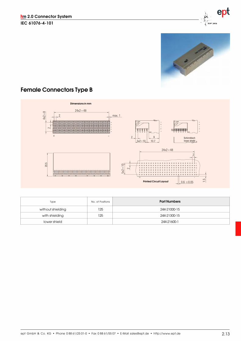
Female Connectors Type B
Dimensions in mm
Printed Circuit Layout
Type No. of Positions Part Numbers
without shielding 125 244-21000-15
with shielding 125 244-21300-15
lower shield 244-21600-1

ept GmbH & Co. KG • Phone 0 88 61/25 01-0 • Fax 0 88 61/55 07 • E-Mail [email protected] • http://www.ept.de2.14
2.0 Connector System
IEC 61076-4-101
Male Connectors Type B-22 (Compact PCI P2/P5)
Printd Circuit Layout
Dimensions in mm
Assembly Drawing No. of Positions Row Type Pin lenght Part Numbers
z C 11,25/3,7a A 8,25/3,7b A 8,25/3,7
154 c A 8,25/3,7 243-22310-15d A 8,25/3,7e A 8,25/3,7f C 11,25/3,7
cPCI Telephony Spec. z C 11,25/3,7a * *b * *
154 c * * 243-22311-15d * *e * *f C 11,25/3,7
z C 11,25/3,7a B 9,75/3,7b B 9,75/3,7
154 c B 9,75/3,7 243-22320-15d B 9,75/3,7e B 9,75/3,7f C 11,25/3,7
z T 11,25/16,0a P 9,75/14,5b P 9,75/14,5
154 c P 9,75/14,5 243-22360-15d P 9,75/14,5e P 9,75/14,5f T 11,25/16,0
Note: PCB thickness 1,6 - 2,8 mm Part No. XXX-XXXXX-05Insertion Tool: Part No. 884-701-W22

ept GmbH & Co. KG • Phone 0 88 61/25 01-0 • Fax 0 88 61/55 07 • E-Mail [email protected] • http://www.ept.de 2.15
2.0 Connector System
IEC 61076-4-101
Female Connectors Type B-22 (Compact PCI J2/J5)
Dimensions in mm
Printed Circuit Layout
Type No. of Positions Part Numbers
without shielding 110 244-22000-15
with shielding 110 244-22300-15
lower shield 244-22600-1

ept GmbH & Co. KG • Phone 0 88 61/25 01-0 • Fax 0 88 61/55 07 • E-Mail [email protected] • http://www.ept.de2.16
2.0 Connector System
IEC 61076-4-101
Male Connectors Type B-19 (VME J0 and C-PCI P3)
Assembly Drawing No. of Positions Row Type Pin length Part Numbers
z – –/–a A 8,25/3,7b A 8,25/3,7
95 c A 8,25/3,7 243-23010-15d A 8,25/3,7e A 8,25/3,7f – –/–
z C 11,25/3,7a A 8,25/3,7b A 8,25/3,7
133 c A 8,25/3,7 243-23310-15d A 8,25/3,7e A 8,25/3,7f C 11,25/3,7
z C 11,25/3,7a B 9,75/3,7b B 9,75/3,7
133 c B 9,75/3,7 243-23320-15d B 9,75/3,7e B 9,75/3,7f C 11,25/3,7
z T 11,25/16,0a P 9,75/14,5b P 9,75/14,5
133 c P 9,75/14,5 243-23360-15d P 9,75/14,5e P 9,75/14,5f T 11,25/16,0
Dimensions in mm
Printed Circuit Layout
Note: PCB thickness 1,6 - 2,8 mm Part No. XXX-XXXXX-05Insertion Tool: Part No. 884-701-W19

ept GmbH & Co. KG • Phone 0 88 61/25 01-0 • Fax 0 88 61/55 07 • E-Mail [email protected] • http://www.ept.de 2.17
2.0 Connector System
IEC 61076-4-101
Female Connectors Type B-19 (VME P0 and C-PCI J3)
Dimensions in mm
Printed Circuit Layout
Type No. of Positions Part Numbers
without shielding 95 244-23000-15
with shielding 95 244-23300-15
lower shield 244-23600-1

ept GmbH & Co. KG • Phone 0 88 61/25 01-0 • Fax 0 88 61/55 07 • E-Mail [email protected] • http://www.ept.de2.18
2.0 Connector System
IEC 61076-4-101
Male Connectors Type C
Printed CircuitLayout
Dimensions in mm
Assembly Drawing No. of Positions Row Type Pin length Part Numbers
z – –/–a A 8,25/3,7b A 8,25/3,7
55 c A 8,25/3,7 243-31010-15d A 8,25/3,7e A 8,25/3,7f – –/–
z – –/–a B 9,75/3,7b B 9,75/3,7
55 c B 9,75/3,7 243-31020-15d B 9,75/3,7e B 9,75/3,7f – –/–
z C 11,25/3,7a A 8,25/3,7b A 8,25/3,7
77 c A 8,25/3,7 243-31310-15d A 8,25/3,7e A 8,25/3,7f C 11,25/3,7
z C 11,25/3,7a B 9,75/3,7b B 9,75/3,7
77 c B 9,75/3,7 243-31320-15d B 9,75/3,7e B 9,75/3,7f C 11,25/3,7
Note: PCB thickness 1,6 - 2,8 mm Part No. XXX-XXXXX-05Insertion Tool: Part No. 884-702-W11

ept GmbH & Co. KG • Phone 0 88 61/25 01-0 • Fax 0 88 61/55 07 • E-Mail [email protected] • http://www.ept.de 2.19
2.0 Connector System
IEC 61076-4-101
Female Connectors Type C
Printed CircuitLayout
Dimensions in mm
Type No. of Positions Part Numbers
without shielding 55 244-31000-15
with shielding 55 244-31300-15
lower shield 244-31600-1

ept GmbH & Co. KG • Phone 0 88 61/25 01-0 • Fax 0 88 61/55 07 • E-Mail [email protected] • http://www.ept.de2.20
2.0 Connector System
IEC 61076-4-101
Male Connectors Type AB-25
Dimensions in mm
Printed Circuit Layout
Assembly Drawing No. of Positions Row Type Pin length Part Numbers
z – –/–a A 8,25/3,7b A 8,25/3,7
125 c A 8,25/3,7 243-61010-15d A 8,25/3,7e A 8,25/3,7f – –/–
z C 11,25/3,7a A 8,25/3,7b A 8,25/3,7
169 c A 8,25/3,7 243-61310-15d A 8,25/3,7e A 8,25/3,7f C 11,25/3,7
z C 11,25/3,7a B 9,75/3,7b B 9,75/3,7
169 c B 9,75/3,7 243-61320-15d B 9,75/3,7e B 9,75/3,7f C 11,25/3,7
z T 11,25/16,0a P 9,75/14,5b P 9,75/14,5
169 c P 9,75/14,5 243-61360-15d P 9,75/14,5e P 9,75/14,5f T 11,25/16,0
Note: PCB thickness 1,6 - 2,8 mm Part No. XXX-XXXXX-05Insertion Tool: Part No. 884-701-W25

ept GmbH & Co. KG • Phone 0 88 61/25 01-0 • Fax 0 88 61/55 07 • E-Mail [email protected] • http://www.ept.de 2.21
2.0 Connector System
IEC 61076-4-101
Female Connectors Type AB-25
Dimensions in mm
Printed Circuit Layout
Type No. of Positions Part Numbers
connectors without shielding 125 244-61000-15
connectors with shielding 125 244-61300-15
lower shield 244-11600-1

ept GmbH & Co. KG • Phone 0 88 61/25 01-0 • Fax 0 88 61/55 07 • E-Mail [email protected] • http://www.ept.de2.22
2.0 Connector System
IEC 61076-4-101
Male Connectors Type AB-22
Dimensions in mm
Printed Circuit Layout
Assembly Drawing No. of Positions Row Type Pin length Part Numbers
z – –/–a A 8,25/3,7b A 8,25/3,7
110 c A 8,25/3,7 243-62010-15d A 8,25/3,7e A 8,25/3,7f – –/–
z C 11,25/3,7a A 8,25/3,7b A 8,25/3,7
146 c A 8,25/3,7 243-62310-15d A 8,25/3,7e A 8,25/3,7f C 11,25/3,7
z C 11,25/3,7a B 9,75/3,7b B 9,75/3,7
146 c B 9,75/3,7 243-62320-15d B 9,75/3,7e B 9,75/3,7f C 11,25/3,7
z T 11,25/16,0a P 9,75/14,5b P 9,75/14,5
146 c P 9,75/14,5 243-62360-15d P 9,75/14,5e P 9,75/14,5f T 11,25/16,0
Note: PCB thickness 1,6 - 2,8 mm Part No. XXX-XXXXX-05Insertion Tool: Part No. 884-701-W22

ept GmbH & Co. KG • Phone 0 88 61/25 01-0 • Fax 0 88 61/55 07 • E-Mail [email protected] • http://www.ept.de 2.23
2.0 Connector System
IEC 61076-4-101
Female Connectors Type AB-22
Dimensions in mm
Printed Circuit Layout
Type No. of Positions Part Numbers
connectors without shielding 110 244-62000-15
connectors with shielding 110 244-62300-15

ept GmbH & Co. KG • Phone 0 88 61/25 01-0 • Fax 0 88 61/55 07 • E-Mail [email protected] • http://www.ept.de2.24
2.0 Connector System
IEC 61076-4-101
Dimensions in mm
Printed Circuit Layout
Male Connectors Type AB-19
Assembly Drawing No. of Positions Row Type Pin length Part Numbers
z – –/–a A 8,25/3,7b A 8,25/3,7
95 c A 8,25/3,7 243-63010-15d A 8,25/3,7e A 8,25/3,7f – –/–
z C 11,25/3,7a A 8,25/3,7b A 8,25/3,7
127 c A 8,25/3,7 243-63310-15d A 8,25/3,7e A 8,25/3,7f C 11,25/3,7
z C 11,25/3,7a B 9,75/3,7b B 9,75/3,7
127 c B 9,75/3,7 243-63320-15d B 9,75/3,7e B 9,75/3,7f C 11,25/3,7
z T 11,25/16,0a P 9,75/14,5b P 9,75/14,5
127 c P 9,75/14,5 243-63360-15d P 9,75/14,5e P 9,75/14,5f T 11,25/16,0
Note: PCB thickness 1,6 - 2,8 mm Part No. XXX-XXXXX-05Insertion Tool: Part No. 884-701-W19

ept GmbH & Co. KG • Phone 0 88 61/25 01-0 • Fax 0 88 61/55 07 • E-Mail [email protected] • http://www.ept.de 2.25
2.0 Connector System
IEC 61076-4-101
Female Connectors Type AB-19
Dimensions in mm
Printed Circuit Layout
Type No. of Positions Part Numbers
connectors without shielding 95 244-63000-15
connectors with shielding 95 244-63300-15

ept GmbH & Co. KG • Phone 0 88 61/25 01-0 • Fax 0 88 61/55 07 • E-Mail [email protected] • http://www.ept.de2.26
2.0 Connector System
IEC 61076-4-101
Male Connectors Type Compact PCI (P1+P2/P4+P5)
Printed Circuit Layout
Dimensions in mm
* Attention: Please consider the different pin length in the assembly drawing. Is used for Compact PCIInsertion Tool: Part No. 884-703-W47On Request: Telephony Spec./Hot SwapNote: PCB thickness 1,6 - 2,8 mm Part No. XXX-XXXXX-05
Assembly Drawing No. of Pos. Row Type Pin length Part Numbers
z C 11,25/3,7a B 9,75/3,7b * * /3,7
308 c * * /3,7 243-12322-15d * * /3,7e B 9,75/3,7f C 11,25/3,7
z C 11,25/3,7a A 8,25/3,7b A 8,25/3,7
308 c A 8,25/3,7 243-12310-15d A 8,25/3,7e A 8,25/3,7f C 11,25/3,7
z T 11,25/16,0a P 9,75/14,5b P 9,75/14,5
308 c P 9,75/14,5 243-12360-15d P 9,75/14,5e P 9,75/14,5f T 11,25/16,0

ept GmbH & Co. KG • Phone 0 88 61/25 01-0 • Fax 0 88 61/55 07 • E-Mail [email protected] • http://www.ept.de 2.27
Engineering Notes

ept GmbH & Co. KG • Phone 0 88 61/25 01-0 • Fax 0 88 61/55 07 • E-Mail [email protected] • http://www.ept.de2.28
2.0 Connector System
IEC 61076-4-101
Male Connectors Type D
Printed Circuit Layout
Dimensions in mm
Assembly Drawing No. of Positions Row Type Pin length Part Numbers
z – –/–a A 8,25/3,7b A 8,25/3,7c A 8,25/3,7d A 8,25/3,7
176 e A 8,25/3,7 245-11010-15
f A 8,25/3,7g A 8,25/3,7h A 8,25/3,7y – –/–
z C 11,25/3,7a A 8,75/3,7b A 8,75/3,7c A 8,75/3,7d A 8,75/3,7
220 e A 8,75/3,7 245-11310-15
f A 8,75/3,7g A 8,75/3,7h A 8,75/3,7y C 11,25/3,7
Note: PCB thickness 1,6 - 2,8 mm Part No. XXX-XXXXX-05
Insertion Tool: Part Number 884-710-W25

ept GmbH & Co. KG • Phone 0 88 61/25 01-0 • Fax 0 88 61/55 07 • E-Mail [email protected] • http://www.ept.de 2.29
2.0 Connector System
IEC 61076-4-101
Female Connectors Type D
Dimensions in mm
Type No. of Positions Part Numbers
connector without shielding 176 246-11000-15
connector with shielding 176 246-11300-15
lower shield 246-11600-1
Printed CircuitLayout
ept GmbH & Co. KG • Phone 0 88 61/25 01-0 • Fax 0 88 61/55 07 • E-Mail [email protected] • http://www.ept.de2.30
2.0 Connector System
IEC 61076-4-101
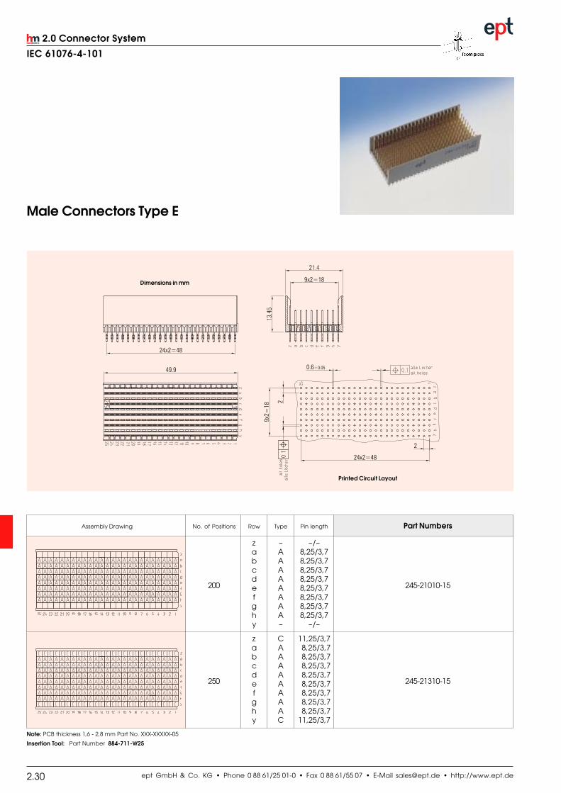
Assembly Drawing No. of Positions Row Type Pin length Part Numbers
z – –/–a A 8,25/3,7b A 8,25/3,7c A 8,25/3,7d A 8,25/3,7
200 e A 8,25/3,7 245-21010-15
f A 8,25/3,7g A 8,25/3,7h A 8,25/3,7y – –/–
z C 11,25/3,7a A 8,25/3,7b A 8,25/3,7c A 8,25/3,7d A 8,25/3,7
250 e A 8,25/3,7 245-21310-15
f A 8,25/3,7g A 8,25/3,7h A 8,25/3,7y C 11,25/3,7
Male Connectors Type E
Printed Circuit Layout
Dimensions in mm
Note: PCB thickness 1,6 - 2,8 mm Part No. XXX-XXXXX-05
Insertion Tool: Part Number 884-711-W25

ept GmbH & Co. KG • Phone 0 88 61/25 01-0 • Fax 0 88 61/55 07 • E-Mail [email protected] • http://www.ept.de 2.31
2.0 Connector System
IEC 61076-4-101
Female Connectors Type E
Dimensions in mm
Type No. of Positions Part Numbers
connector without shielding 200 246-21000-15
connector with shielding 200 246-21300-15
lower shield 246-21600-1
Printed CircuitLayout

ept GmbH & Co. KG • Phone 0 88 61/25 01-0 • Fax 0 88 61/55 07 • E-Mail [email protected] • http://www.ept.de2.32
2.0 Connector System
IEC 61076-4-101
Male Connectors Type F
Printed Circuit Layout
Dimensions in mm
Assembly Drawing No. of Positions Row Type Pin length Part Numbers
z – –/–a A 8,25/3,7b A 8,25/3,7c A 8,25/3,7d A 8,25/3,7
88 e A 8,25/3,7 245-31010-15
f A 8,25/3,7g A 8,25/3,7h A 8,25/3,7y – –/–
z C 11,25/3,7a A 8,75/3,7b A 8,75/3,7c A 8,75/3,7d A 8,75/3,7
110 e A 8,75/3,7 245-31310-15
f A 8,75/3,7g A 8,75/3,7h A 8,75/3,7y C 11,25/3,7
Note: PCB thickness 1,6 - 2,8 mm Part No. XXX-XXXXX-05
Insertion Tool: Part Number 884-713-W11

ept GmbH & Co. KG • Phone 0 88 61/25 01-0 • Fax 0 88 61/55 07 • E-Mail [email protected] • http://www.ept.de 2.33
2.0 Connector System
IEC 61076-4-101
Female Connectors Type F
Dimensions in mm
Printed CircuitLayout
Type No. of Positions Part Numbers
connector without shielding 88 246-31000-15
connector with shielding 88 246-31300-15
lower shield 246-31600-1
ept GmbH & Co. KG • Phone 0 88 61/25 01-0 • Fax 0 88 61/55 07 • E-Mail [email protected] • http://www.ept.de2.34
2.0 Connector System
IEC 61076-4-101
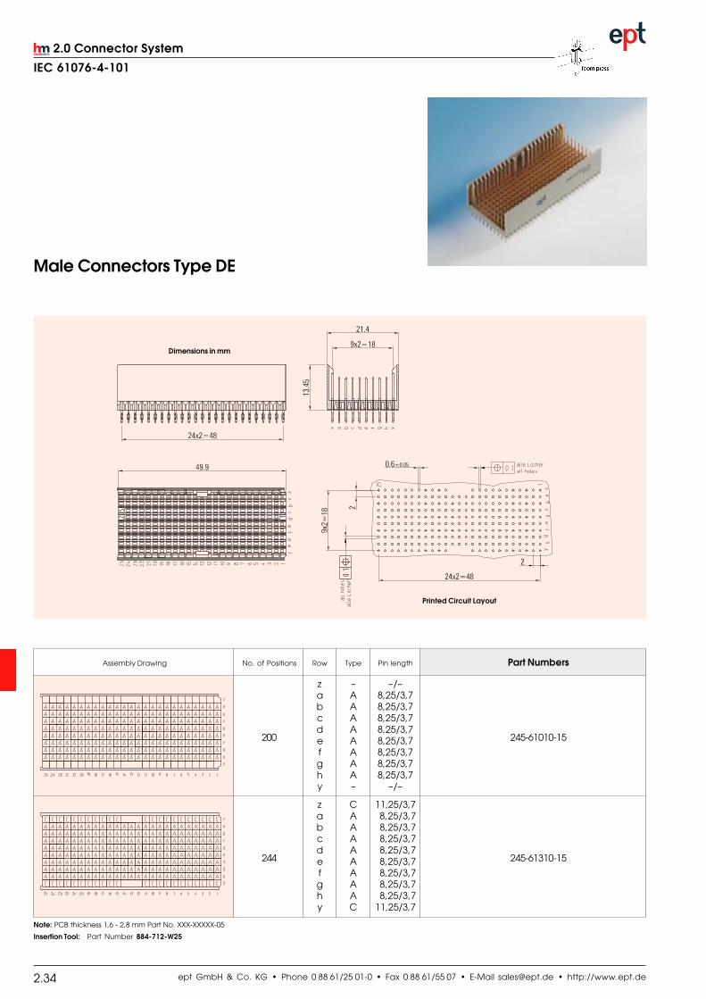
Assembly Drawing No. of Positions Row Type Pin length Part Numbers
z – –/–a A 8,25/3,7b A 8,25/3,7c A 8,25/3,7d A 8,25/3,7
200 e A 8,25/3,7 245-61010-15
f A 8,25/3,7g A 8,25/3,7h A 8,25/3,7y – –/–
z C 11,25/3,7a A 8,25/3,7b A 8,25/3,7c A 8,25/3,7d A 8,25/3,7
244 e A 8,25/3,7 245-61310-15
f A 8,25/3,7g A 8,25/3,7h A 8,25/3,7y C 11,25/3,7
Male Connectors Type DE
Printed Circuit Layout
Dimensions in mm
Note: PCB thickness 1,6 - 2,8 mm Part No. XXX-XXXXX-05
Insertion Tool: Part Number 884-712-W25
ept GmbH & Co. KG • Phone 0 88 61/25 01-0 • Fax 0 88 61/55 07 • E-Mail [email protected] • http://www.ept.de 2.35
2.0 Connector System
IEC 61076-4-101
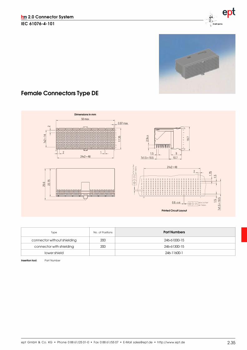
Female Connectors Type DE
Dimensions in mm
Type No. of Positions Part Numbers
connector without shielding 200 246-61000-15
connector with shielding 200 246-61300-15
lower shield 246-11600-1
Insertion tool: Part Number
Printed Circuit Layout

ept GmbH & Co. KG • Phone 0 88 61/25 01-0 • Fax 0 88 61/55 07 • E-Mail [email protected] • http://www.ept.de2.36
2.0 Connector System
IEC 61076-4-101
Male Connectors Type L
Dimensions in mm
Printed Circuit Layout
Assembly Drawing No. of Positions Row special contact Part Number
power / 243-51000cable contacts
6 –
pressfit coax 243-53000
Insertion Tool: Part Number 884-707-W1

ept GmbH & Co. KG • Phone 0 88 61/25 01-0 • Fax 0 88 61/55 07 • E-Mail [email protected] • http://www.ept.de 2.37
2.0 Connector System
IEC 61076-4-101
Female Connectors Type L
Dimensions in mm
Printed Circuit Layout
Type No. of Positions Part Number
connector without shielding 6 244-51000

ept GmbH & Co. KG • Phone 0 88 61/25 01-0 • Fax 0 88 61/55 07 • E-Mail [email protected] • http://www.ept.de2.38
2.0 Connector System
IEC 61076-4-101
Male Connectors Type M
Dimensions in mm
Printed Circuit Layout
Assembly Drawing No. of Positions Row Type Pin length special contacts Part Numbers
z – –/–a A 8,25/3,7 power / 243-41010-15b A 8,25/3,7 cable contacts
55+3 c A 8,25/3,7d A 8,25/3,7e A 8,25/3,7 pressfit coax 243-42010-15f – –/–
z C 11,25/3,7a A 8,25/3,7 power / 243-41310-15b A 8,25/3,7 cable contacts
77+3 c A 8,25/3,7d A 8,25/3,7e A 8,25/3,7 pressfit coax 243-42310-15f C 11,25/3,7
Insertion Tool: Part Number 884-707-W2

ept GmbH & Co. KG • Phone 0 88 61/25 01-0 • Fax 0 88 61/55 07 • E-Mail [email protected] • http://www.ept.de 2.39
2.0 Connector System
IEC 61076-4-101
Female Connectors Type M
Dimensions in mm
Printed Circuit Layout
Type No. of Positions Part Numbers
connector without shielding 55+3 244-41000-15
connector with shielding 55+3 244-41300-15
lower shield 244-31600-1

ept GmbH & Co. KG • Phone 0 88 61/25 01-0 • Fax 0 88 61/55 07 • E-Mail [email protected] • http://www.ept.de2.40
2.0 Connector System
IEC 61076-4-101
Male Connectors Type N
Dimensions in mm
Printed Circuit Layout
Assembly Drawing No. of Positions Row special contact Part Number
power / 243-52000cable contacts
3 –
pressfit coax 243-54000
Insertion Tool: Part Number 884-707-W3

ept GmbH & Co. KG • Phone 0 88 61/25 01-0 • Fax 0 88 61/55 07 • E-Mail [email protected] • http://www.ept.de 2.41
2.0 Connector System
IEC 61076-4-101
Type No. of Positions Part Number
connector without shielding 3 244-52000
Female Connectors Type N
Dimensions in mm
Printed Circuit Layout

ept GmbH & Co. KG • Phone 0 88 61/25 01-0 • Fax 0 88 61/55 07 • E-Mail [email protected] • http://www.ept.de2.42
2.0 Connector System
IEC 61076-4-101
High Current Contactsfor use with Type L, M and N
Termination Methods Operating Current Part Numbers
Solder Female Contact
30 A 916-42002
Press-fit Female Contact
40 A 916-62002
Press-fit Male Contact
40 A 915-61002
Press-fit Contact
Dimensions in mm25-80 m Cu
5-12 m Sn
min. 0.1
3.5–0.076
min
. 2.3
6
3.76
4.75
3.57
6.07
17.17
5.21
Mating Area
Au over NiPressfit AreaAu over Ni
Silicon Rubber
Solder Contact
Printed Circuit LayoutPrinted Circuit Layout
Press-fit Contact

ept GmbH & Co. KG • Phone 0 88 61/25 01-0 • Fax 0 88 61/55 07 • E-Mail [email protected] • http://www.ept.de 2.43
2.0 Connector System
IEC 61076-4-101
Coaxial Contacts for use with Type L, M and N
Termination Methods Impedance Part Numbers
for male connectors243-42... / 243-53... / 243-54...
50 W 916-63002
for female connectors
50 W 915-64002
for male connectors
Dimensions in mm
for female connectors
Printed Circuit Layout Printed Circuit Layout

ept GmbH & Co. KG • Phone 0 88 61/25 01-0 • Fax 0 88 61/55 07 • E-Mail [email protected] • http://www.ept.de2.44
2.0 Connector System
IEC 61076-4-101
Shrouds for Male Connectors Type A, B,B-22, B-19 and C
Dimensions in mm
On request: other hights and special shrouds
PCB thickness < <3,2 mm 3,2 - 4 mm 4,0 - 4,8 mm > 4,8 mm
X 6,3 mm 4,9 mm 4,5 mm 3,7 mm 2,9 mm
Shroud 16,75 mm 15,35 mm 14,95 mm 14,15 mm 13,35 mm
Connector Type Part Numbers
A 243-5525-5 243-5525-4 243-5525-1 243-5525-2 243-5525-3
B - - 243-5625-1 243-5625-2 243-5625-3
B-22 243-5622-5 243-5622-4 243-5622-1 243-5622-2 243-5622-3
B-19 243-5619-5 243-5619-4 243-5619-1 243-5619-2 243-5619-3
C - - 243-5511-1 243-5511-2 243-5511-3

ept GmbH & Co. KG • Phone 0 88 61/25 01-0 • Fax 0 88 61/55 07 • E-Mail [email protected] • http://www.ept.de 2.45
2.0 Connector System
IEC 61076-4-101
Shrouds for Male Connectors Type AB
Dimensions in mm
On request: other hights and special shrouds
PCB thickness < < 3,2 mm 3,2 - 4 mm 4,0 - 4,8 mm > 4,8 mm
X 6,3 mm 4,9 mm 4,5 mm 3,7 mm 2,9 mm
Shroud hight 16,75 mm 15,35 mm 14,95 mm 14,15 mm 13,35 mm
Connector Type Part Numbers
AB-25 - - 243-5725-1 243-5725-2 243-5725-3
AB-22 243-5722-5 243-5722-4 243-5722-1 243-5722-2 243-5722-3
AB-19 243-5719-5 243-5719-4 243-5719-1 243-5719-2 243-5719-3
ept GmbH & Co. KG • Phone 0 88 61/25 01-0 • Fax 0 88 61/55 07 • E-Mail [email protected] • http://www.ept.de2.46
2.0 Connector System
IEC 61076-4-101
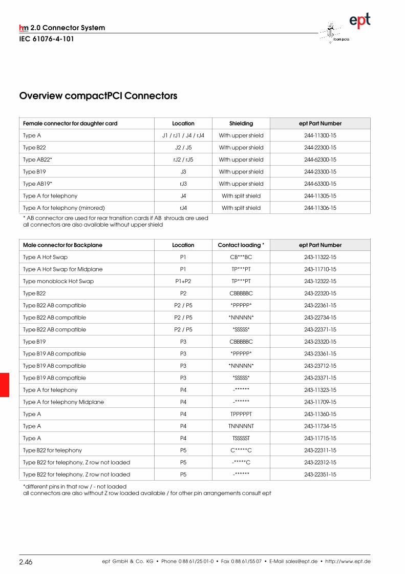
Male connector for Backplane Location Contact loading * ept Part Number
Type A Hot Swap P1 CB***BC 243-11322-15
Type A Hot Swap for Midplane P1 TP***PT 243-11710-15
Type monoblock Hot Swap P1+P2 TP***PT 243-12322-15
Type B22 P2 CBBBBBC 243-22320-15
Type B22 AB compatible P2 / P5 *PPPPP* 243-22361-15
Type B22 AB compatible P2 / P5 *NNNNN* 243-22734-15
Type B22 AB compatible P2 / P5 *SSSSS* 243-22371-15
Type B19 P3 CBBBBBC 243-23320-15
Type B19 AB compatible P3 *PPPPP* 243-23361-15
Type B19 AB compatible P3 *NNNNN* 243-23712-15
Type B19 AB compatible P3 *SSSSS* 243-23371-15
Type A for telephony P4 -****** 243-11323-15
Type A for telephony Midplane P4 -****** 243-11709-15
Type A P4 TPPPPPT 243-11360-15
Type A P4 TNNNNNT 243-11734-15
Type A P4 TSSSSST 243-11715-15
Type B22 for telephony P5 C*****C 243-22311-15
Type B22 for telephony, Z row not loaded P5 -*****C 243-22312-15
Type B22 for telephony, Z row not loaded P5 -****** 243-22351-15
*different pins in that row / - not loadedall connectors are also without Z row loaded available / for other pin arrangements consult ept
Female connector for daughter card Location Shielding ept Part Number
Type A J1 / rJ1 / J4 / rJ4 With upper shield 244-11300-15
Type B22 J2 / J5 With upper shield 244-22300-15
Type AB22* rJ2 / rJ5 With upper shield 244-62300-15
Type B19 J3 With upper shield 244-23300-15
Type AB19* rJ3 With upper shield 244-63300-15
Type A for telephony J4 With split shield 244-11305-15
Type A for telephony (mirrored) rJ4 With split shield 244-11306-15
* AB connector are used for rear transition cards if AB shrouds are usedall connectors are also available without upper shield
Overview compactPCI Connectors

ept GmbH & Co. KG • Phone 0 88 61/25 01-0 • Fax 0 88 61/55 07 • E-Mail [email protected] • http://www.ept.de 2.47
2.0 Connector System
IEC 61076-4-101
Shrouds Location height Base thickness ept Part Number
Type A P1 / P4 16,75 mm 6,3 mm 243-5525-5
Type A P1 / P4 15,35 mm 4,9 mm 243-5525-4
Type A P1 / P4 14,95 mm 4,5 mm 243-5525-1
Type A P1 / P4 14,15 mm 3,7 mm 243-5525-2
Type A P1 / P4 13,35 mm 2,9 mm 243-5525-3
Type AB22 P2 / P5 16,75 mm 6,3 mm 243-5722-5
Type AB22 P2 / P5 15,35 mm 4,9 mm 243-5722-4
Type AB22 P2 / P5 14,95 mm 4,5 mm 243-5722-1
Type AB22 P2 / P5 14,15 mm 3,7 mm 243-5722-2
Type AB22 P2 / P5 13,35 mm 2,9 mm 243-5722-3
Type AB19 P3 16,75 mm 6,3 mm 243-5719-5
Type AB19 P3 15,35 mm 4,9 mm 243-5719-4
Type AB19 P3 14,95 mm 4,5 mm 243-5719-1
Type AB19 P3 14,15 mm 3,7 mm 243-5719-2
Type AB19 P3 13,35 mm 2,9 mm 243-5719-3
The height / base thickness of the shrouds depend on the thickness of the Backplane
Coding keys Color application ept Part Number
Male Backplane Brilliant Blue 5V – P1 243-8014
Male Backplane Cadmium Yellow 3,3V – P1 243-8031
Male Backplane Strawberry red Telephony – P4 243-8012
Female Daughtercard Brilliant Blue 5V – J1 244-8014
Female Daughtercard Cadmium Yellow 3,3V – J1 244-8031
Female Daughtercard Strawberry red Telephony – J4 244-8012

ept GmbH & Co. KG • Phone 0 88 61/25 01-0 • Fax 0 88 61/55 07 • E-Mail [email protected] • http://www.ept.de2.48
2.0 Connector System
IEC 61076-4-101
srotcennocelaM
yekgnidoC .oNedoC ruoloC srebmuNtraP
6321nworbtuN1108LAR
1108-342
8421deryrrebwartS
8103LAR.cepSynohpeleT
2108-342
6531calileulB5004LAR
3108-342
7651eulbtnallirB
7005LARICP-CV0,5
4108-342
8752neergadeseR
1106LAR1208-342
6543wolleymuimdaC
1201LARICP-CV3,3
1308-342
7643yergetalS5107LAR
2308-342
8743eulbleetS1105LAR
3308-342
8653egnaroletsaP
3002LAR4308-342
8764wolleyrehcO
4201LAR1408-342
Coding Devices
srotcennocelameF
yekgnidoC .oNedoC ruoloC srebmuNtraP
8754nworbtuN1108LAR
1108-442
7653deryrrebwartS
8103LAR.cepSynohpeleT
2108-442
8742calileulB5004LAR
3108-442
8432eulbtnaillirB
7005LARICP-CV0,5
4108-442
6431neergadeseR
1106LAR1208-442
8721wolleymuimdaC
1201LARICP-CV3,3
1308-442
8521yergetalS5107LAR
2308-442
6521eulbleetS1105LAR
3308-442
7421egnaroletsaP
3002LAR4308-442
5321wolleyrehcO
4201LAR1408-442

ept GmbH & Co. KG • Phone 0 88 61/25 01-0 • Fax 0 88 61/55 07 • E-Mail [email protected] • http://www.ept.de 2.49
2.0 Connector System
IEC 61076-4-101
Fax request (5+2)
Assembly reference:
In order to be able to load the connectors
economically we recommend a serial
determination of the contact length. If only
position 1 of a line is indicated, the entire line is
loaded with this contact length. Exceptions can
be registered at the respective position.
Surface:Quality level 2 acc. to IEC 61076-4-101.
Au over PdNi over Ni.
Ma
le-Typ
eB
AC
KM
LP
NQ
SR
T
Please quote me for _________________ pieces.
Please send me ________________ sample pieces.
Company Phone Number
First Name Last Name Fax Number
Adress E-Mail
Adress Signature

ept GmbH & Co. KG • Phone 0 88 61/25 01-0 • Fax 0 88 61/55 07 • E-Mail [email protected] • http://www.ept.de2.50
2.0 Connector System
IEC 61076-4-101
Fax request (8+2)
Assembly reference:
In order to be able to load the connectors economically we recommend a serial determination of the contact length. If only position
1 of a line is indicated, the entire line is loaded with this contact length. Exceptions can be registered at the respective position.
Surface:Quality level 2 acc. to IEC 61076-4-101.
Au over PdNi over Ni.
Ma
le-Typ
eB
AC
KM
LP
NQ
SR
T
Please quote me for _________________ pieces.
Please send me ________________ sample pieces.
Company Phone Number
First Name Last Name Fax Number
Adress E-Mail
Adress Signature

ept GmbH & Co. KG • Phone 0 88 61/25 01-0 • Fax 0 88 61/55 07 • E-Mail [email protected] • http://www.ept.de 2.51
2.0 Connector System
IEC 61076-4-101
Fax request AB
Assembly reference:
In order to be able to load the connectors economically we recommend a serial determination of the contact length. If only position
1 of a line is indicated, the entire line is loaded with this contact length. Exceptions can be registered at the respective position.
Surface:Quality level 2 acc. to IEC 61076-4-101.
Au over PdNi over Ni.
Ma
le-Typ
eB
AC
KM
LP
NQ
SR
T
Please quote me for _________________ pieces.
Please send me ________________ sample pieces.
Company Phone Number
First Name Last Name Fax Number
Adress E-Mail
Adress Signature