identifying cutting processes and tools
TRANSCRIPT
ISSN 1068-798X, Russian Engineering Research, 2008, Vol. 28, No. 7, pp. 681–691. © Allerton Press, Inc., 2008.Original Russian Text © Yu.A. Novoselov, 2008, published in Vestnik Mashinostroeniya, 2008, No. 7, pp. 61–71.
681
Current requirements regarding the prompt andthorough computerization of manufacturing call for aradical revision of scientific, methodological, engineer-ing, organizational, and other principles of manufactur-ing. This should help to create the preconditions for theefficient and universal utilization of computers in tech-nological preparations for the production, design, andautomation of manufacturing systems. In our view,however, there has been very little progress in thatregard with respect to cutting processes and tools inmanufacturing. We consider this field in the presentwork.
More than 10
3
kinematic versions of the cutting pro-cess [3], 10
4
designs of cutting tools, 10
4
fundamentallydifferent models of metal-cutting machines [4], and10
3
types of machined materials [5] (to say nothing ofthe range of tool materials) are employed in manufac-turing, according to the analysis of [1, 2]. The numberof fundamental designs of machine-tool attachments ispractically incalculable. The following factors furthercomplicate the situation:
the cutting processes employed are very different; inmost cases, they have little in common (for example,turning, milling, hobbing, and broaching);
each type of cutting process is described by a differ-ent set of parameters, with practically no overlap;
different cutting processes were investigated in dif-ferent historical periods, in different cities, by differentresearchers, using different methods, and on differentapparatus; therefore, comparison of the results is notfeasible.
In such conditions, the creation of any general the-ory or, at least, consistent system of analogies is simplyimpossible.
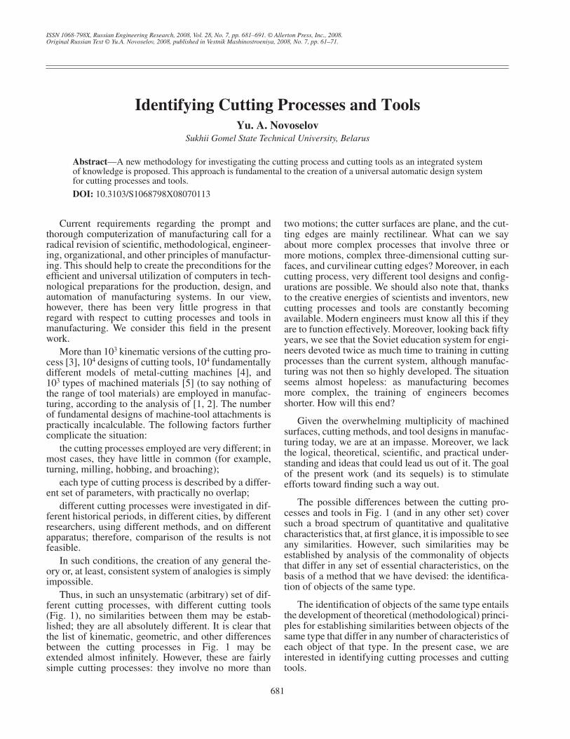
Thus, in such an unsystematic (arbitrary) set of dif-ferent cutting processes, with different cutting tools(Fig. 1), no similarities between them may be estab-lished; they are all absolutely different. It is clear thatthe list of kinematic, geometric, and other differencesbetween the cutting processes in Fig. 1 may beextended almost infinitely. However, these are fairlysimple cutting processes: they involve no more than
two motions; the cutter surfaces are plane, and the cut-ting edges are mainly rectilinear. What can we sayabout more complex processes that involve three ormore motions, complex three-dimensional cutting sur-faces, and curvilinear cutting edges? Moreover, in eachcutting process, very different tool designs and config-urations are possible. We should also note that, thanksto the creative energies of scientists and inventors, newcutting processes and tools are constantly becomingavailable. Modern engineers must know all this if theyare to function effectively. Moreover, looking back fiftyyears, we see that the Soviet education system for engi-neers devoted twice as much time to training in cuttingprocesses than the current system, although manufac-turing was not then so highly developed. The situationseems almost hopeless: as manufacturing becomesmore complex, the training of engineers becomesshorter. How will this end?
Given the overwhelming multiplicity of machinedsurfaces, cutting methods, and tool designs in manufac-turing today, we are at an impasse. Moreover, we lackthe logical, theoretical, scientific, and practical under-standing and ideas that could lead us out of it. The goalof the present work (and its sequels) is to stimulateefforts toward finding such a way out.
The possible differences between the cutting pro-cesses and tools in Fig. 1 (and in any other set) coversuch a broad spectrum of quantitative and qualitativecharacteristics that, at first glance, it is impossible to seeany similarities. However, such similarities may beestablished by analysis of the commonality of objectsthat differ in any set of essential characteristics, on thebasis of a method that we have devised: the identifica-tion of objects of the same type.
The identification of objects of the same type entailsthe development of theoretical (methodological) princi-ples for establishing similarities between objects of thesame type that differ in any number of characteristics ofeach object of that type. In the present case, we areinterested in identifying cutting processes and cuttingtools.
Identifying Cutting Processes and Tools
Yu. A. Novoselov
Sukhii Gomel State Technical University, Belarus
Abstract
—A new methodology for investigating the cutting process and cutting tools as an integrated systemof knowledge is proposed. This approach is fundamental to the creation of a universal automatic design systemfor cutting processes and tools.
DOI:
10.3103/S1068798X08070113
682
RUSSIAN ENGINEERING RESEARCH
Vol. 28
No. 7
2008
NOVOSELOV
The history of the science of cutting processes indi-cates that only two coordinate systems have been usedin the study of cutting processes: a kinematic systemthat is associated with motion in the cutting process andorients that process in space; and the tool coordinatesystem, associated with the tool and intended to specifythe shape and geometry of the tool as a geometric body.When it was necessary to represent the tool geometry insome intermediate situation, unhelpful expressionssuch as the following might be used: “We consider theangles of the tool in the kinematic coordinate system,neglecting the supply motion because it has little influ-ence on the cutting process.” To avoid such vague andrhetorical language when developing state standardsregarding terms and definitions for cutting processesand tools [6–8], we introduced a third (intermediate)coordinate system in the standard [6]; this may also beknown as the static coordinate system. In this system,the basic plane is perpendicular to the velocity vector ofthe primary cutting motion; the cutting plane is tangen-tial to the cutting edge and passes through the velocityvector of the primary motion; and the primary secantplane passes through the velocity vector of primarymotion and perpendicular to the projection of the cut-ting edge on the basic plane at the given point of theedge.
Thus, the concept of three coordinate systems (thekinematic, static, and tool systems), was introduced in
[6]. Each system has three mutually perpendicularcoordinate planes: the basic plane
P
v
, the cutting plane
P
n
, and the primary secant plane
P
τ
. These three planesof each system, intersecting at the given point
M
of thecutting edge, regulate the spatial coordination of thecutting process at this point of the tool (more precisely,an infinitesimal section of the cutting edge in the vicin-ity of the point). The most important orienting elementof each system is the basic plane
P
v
, which is perpen-dicular to the velocity vector
v
e
of the resultant (total)motion in the kinematic system; is perpendicular to thevelocity vector
v
of primary motion in the static sys-tem; and is parallel to the basic element of the toolattachment experiencing the greatest cutting load (forexample, the bottom of the cutter, the supporting planeof the hob, etc.) or passes directly through the basic ele-ment itself (for example, through the mill axis, thebroach axis, etc.).
The static coordinate system does not confuse thesystem of cutting concepts, as some have suggested, butrather clarifies it. In fact, as we know, the kinematic sys-tem is required for precise analysis of the cutting pro-cess as an engineering phenomenon, and the tool sys-tem is required to formulate the drawing of the tool.Since these systems are fundamentally different andhave different functions, but are somehow related, theremust also be a system capable of combining them intoa consistent conceptual whole. This is the role of the
M
M MMM
MMM
+
MMMM
M
M
MMM
M
MMM
MMMM
(a) (b) (c) (d) (e)
(f) (g) (h) (i) (j)
(k) (l) (m) (n) (o)
D
pb
D
S
t
D
pb
D
S
b
D
pt
D
S
t
D
pt
D
pb
D
S
b
D
S
t
D
pt
D
pt
D
S
b
D
S
t
D
pb
D
pt
D
S
t
D
S
t
D
pb
D
pt
D
S
t
D
pb
D
S
t
D
pt
D
S
t
D
pb
ψ
ψ
D
S
t
D
pt
Fig. 1.
Unsystematic set of types of cutting processes with different cutting tools.
RUSSIAN ENGINEERING RESEARCH
Vol. 28
No. 7
2008
IDENTIFYING CUTTING PROCESSES AND TOOLS 683
static coordinate system, which is hence of great impor-tance in addressing the problems here considered.
Moreover, as will be shown in subsequent examples,the static system is able to uniquely represent any com-bination of characteristics of any cutting process and itsassociated tools. Finally, only the static coordinate sys-tem clearly and simply corresponds to the technologi-cal coordinate system
XYZ
introduced in [1]. Regretta-bly, as is evident from an analysis of the literature, theutility of the static coordinate system has yet to be fullyacknowledged. In the present work, this concept isexplicated and employed together with the technologi-cal coordinate system. Since the latter is not in commonuse, we recall here its fundamental features:
the coordinate origin
O
is at the given point
M
of thecutting edge;
the
Z
axis is in the direction of the velocity of pri-mary motion at point
M
;the
Y
axis runs along the radius of primary rotarycutting motion;
the
X
axis is parallel to the axis of primary rotarymotion;
the positive direction of the coordinate axes extendstoward the tool’s cutting edge.
When axes
X
and
Y
of this system do not intersectthe cutting edge, i.e., when they are tangential to theprojection of the cutting edge onto the
XY
plane, thepositive direction runs toward the tool or its attachment;in the event of difficulty, it may be chosen arbitrarily.However, it is important to select a right coordinate sys-tem, in which the rotation from the
X
axis to the
Y
axisis counterclockwise when viewed from the end of the
Z
axis. In addition, translational (rectilinear) primary cut-ting motion, where it appears, is taken into account asthe limiting state of rotary motion as the radius tends toinfinity (for example, in broaching key slots).
The foregoing information and the results of thesubsequent discussions are summarized in Fig. 2. Wenow consider this material in more detail.
The relation between the static coordinate systemand the technological coordinate system is that thebasic plane of the static system (
P
v
s
) is aligned with the
XY
plane of the technological coordinate system, withpossible subsequent rotation (where necessary) of twoaxes of one system relative to those of the other systemaround the common third axis (around the
Z
axis of thetechnological system), by an angle equivalent in signif-icance and equal in value to the well-known plane angle
ϕ
. Note that a precise objective definition of
ϕ
has notpreviously been stated, even in the standard [6]. (A def-inition will be proposed in the present work.) In Fig. 2,
ϕ
= 0 is assumed; this ensures complete agreement ofthe static coordinate system and the technological coor-dinate system.
Having related the static coordinate system (
P
v
s
,
P
n
s
,and
P
τ
s
) and the technological coordinate system (
X
,
Y
,and
Z
), we obtain the fundamental principles of the cut-
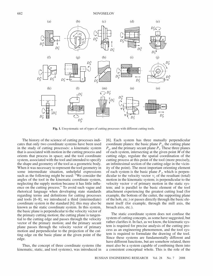
ting process as an engineering phenomenon (Fig. 2).These principles may be used as a key to the identifica-tion of cutting processes and tools. Note the followingaspects of Fig. 2:
two circles, with arrows indicating the possible
rotary motions of the tool ( , ) and blank
( , ), with axes parallel to the
X
axis (notshown in Fig. 2); in principle, these may be primarymotions;
arrows taking account of the two possible transla-
tional (rectilinear) motions of the blank ( , )
and/or tool ( , ) along the coordinate axes
Y
and
Z
; the second of these may be a primary motion;
the cross section of the cutter at the given point
M
ofthe hypothetical cutting edge in the form of a shadedwedge, which may belong (as shown in Fig. 2) to anytool—for example, a cutter
1
, a mill
2
, a broach
3
, or aninverse cutter
4
—provided that tool performs primarymotion (zero values of
ϕ
and the inclination
λ
of thecutting edges are also assumed);
the technological coordinate system
XYZ
with itsorigin
O
at the given point
M
of the cutting edge (axes
Y
and
Z
are shown; the
X
axis is perpendicular to theplane of the figure);
the static coordinate system, with the positions ofthe basic plane
P
v
s
and cutting plane
P
n
s
(the primarysecant plane
P
τs is the plane of the figure).
Of the four elementary motions in the plane of Fig. 2,only three may be primary motions.
1. Rotary primary motion performed by the blank:
either around axis O1 (motion ), which is typi-cal of turning on lathes with tool supply along the X and
DOXt DOX
t '
DOXb DOX
b'
DYb DZ
b
DYt DZ
t
DOXb
12
3
4Y
Z
OM
O1O2
Blank Tool
Pτs
DZb DOX
b'
DOXtDZ
tDOXt'
DOXb
DYt DY
b
Pns
Pns
Pvs Pvs
Fig. 2. Fundamental principles of the cutting process as anengineering phenomenon.
684
RUSSIAN ENGINEERING RESEARCH Vol. 28 No. 7 2008
NOVOSELOV
Y axes and, less often, the Z axis (motions: , not seen
in Fig. 2; , );
or around the O2 axis (motion ), which corre-sponds to boring on the same machine tools, with thesame motions.
2. Rotary primary motion performed by the tool:
either around axis O2 (motion ), which is typi-cal of axial machining (boring, reaming, broaching,countersinking, etc.) on boring machines with supply
along the axis of this motion (motion , not shown in
Fig. 2), milling with supply of the blank (motions
and ) or tool (motions and ) along the Y andZ axes, boring on a boring machine with supply of thetool or blank along the axis of the primary motion
(motion or , not shown in Fig. 2) or radially
(motion or );
or around the axis O1 (motion ), which is typi-cal of turning by an inverse cutting head, thread cuttingby an external hob, and other processes with supply of
the blank or tool along the X axis (motion or ,not shown in Fig. 2), with possible rotation of the blank
around its axis parallel to the X axis (motion ).
3. Translational primary motion performed by:
the tool (motion ), which is typical of planingand chiseling on the corresponding machines with sup-
ply of the blank along the X and Y axes (motions ,
which is not shown in Fig. 2, and ), gear planing andslotting on the corresponding machines with circularopposing supply of the blank and tool around axes par-allel to the Z axis (motions not shown in Fig. 2) and
with radial supply of the blank (motion ), andbroaching and piercing without supply;
or by the blank (motion ) in exceptionally rarecases in the same processes.
Thus, in any cutting process, with any number ofelementary motions (up to and including five), in anycombination or configuration, the primary motion mustbe one of the three motions associated with the cuttingedge at point M in the direction of the vertical Z axis:
(or ), (or ), or (or ). All theother possible elementary motions (of which there maybe as many as four) must have velocities several ordersof magnitude less than that of the primary motion andmay have any spatial position in the adopted coordinatesystem, in contrast to the primary motion. To forestallreaders' objections, we should note that our statement
DXt
DYt DZ
t
DOXb'
DOXt
DXt
DYb
DZb DY
t DZt
DXt DX
b
DYt DY
b
DOXt'
DXb DX
t
DOXb
DZt
DXb
DYb
DYb
DZb
DZb DZ
t DOXb DOX
t DOXb' DOX
t'
regarding the disparate velocities of the primary motionand supply motions does not apply in only one case:when cutting screw channels inclined to the axis at 45°,on a lathe. Such isolated cases are usually set aside forphilosophical consideration and do not figure in appliedtreatments. Hence, the primary cutting motion is themost important technological attribute of the cuttingprocess, and the associated static coordinate system andtechnological coordinate system provide the method-ological basis for the identification of cutting processesand tools.
The plane representation of the cutting process inFig. 2 is unique in that it incorporates, in concise form,the greatest number of generalities and specifics of cut-ting processes. The only processes that it fails toinclude are those with axial (along the X axis) and cir-cular (around the Z axis) supplies, since such motions,on the one hand, are not described in the convenientplane form adopted and, on the other, are less commonthan the others.
The basic representation of the cutting process inFig. 2 permits the following conclusions.
1. This diagram unifies practically all possible cut-ting processes and tools.
2. Depending on which of the three possible primarycutting motions appears in the specific cutting process,the other two automatically become supply motions,together with the motions along the X and Y axes.
3. In rotary primary motion of the blank, its position
(i.e., the position of the motion ) in the diagram isconstant; the position of the tool (i.e., the position of the
arrow ) in the coordinate system XYZ is arbitrary(not shown in Fig. 2).
4. With rotary primary motion of the tool, its posi-
tion (i.e., the position of arrow ) in the diagram isconstant; the position of the blank (i.e., the position of
the arrow ) in the coordinate system XYZ is arbi-trary (not shown in Fig. 2).
5. With translational primary motion of the blank or
tool (i.e., in motion or ), the position of thearrows of the other motions in the diagram may be arbi-trary (not shown in Fig. 2).
6. With extreme variability of the radii of rotarymotion of the blank and tool (from miniature instru-ments to superheavy machinery), whether primary orsupply motion, we may conclude that the diagram inFig. 2 incorporates an infinite number of curvilinearcutting trajectories associated with point O (or M) anddiverging in all directions from the Z axis (a bundle oftrajectories).
7. As is evident from the superscript of the motionsin Fig. 2, the static primary plane Pvs divides the kineticspace of the cutting process (the bundle of trajectoriesnoted in point 6) into two halves: an upper half with
DOXb
DOXt
DOXt
DOXb
DZb DZ
t
RUSSIAN ENGINEERING RESEARCH Vol. 28 No. 7 2008
IDENTIFYING CUTTING PROCESSES AND TOOLS 685
superscript t, corresponding to the action of the tool onthe blank; and a lower half, with superscript b, corre-sponding to the reaction of the blank on the tool.
Forming an integrated (generalized) model of allcutting processes in this way, we may proceed to well-founded differentiation of the model in terms of themost general and most important parameters (i.e.,parameterization of the model), so as to be able toderive (construct) from it any specific known or previ-ously unknown cutting process. Smooth parameteriza-tion of the model is possible by continuous variation ofthe numerical values (including zero) of the followingimportant parameters, over a broad range:
the magnitude and sign of the curvature K = 1/R ofthe trajectory of the primary cutting motion [1]; here Ris the radius of the trajectory of point M of the cuttingedge in primary motion of the tool (in the most generalcase, –∞ < K < +∞);
the magnitude and sign of the angles of rotation ofsecondary (supply) rotational and/or translationalmotions of the blank and/or tool relative to the axes ofthe XYZ system;
the magnitude and sign of the curvature of trajecto-ries of secondary (supply) rotational motions of theblank and/or tool relative to the axes of the XYZ systemor other axes.
Finally, applying the proposed set of parametricmanipulations to the generalized model in Fig. 2 per-mits the reconstitution of any cutting process. However,on account of the differences in generality and compat-ibility of the model parameters, the results of suchmanipulation may not be equivalent. Therefore, forgreater clarity, we introduce two concepts: the cuttingmethod and the cutting procedure.
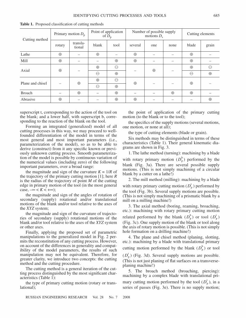
The cutting method is a general iteration of the cut-ting process distinguished by the most significant char-acteristics (Table 1):
the type of primary cutting motion (rotary or trans-lational);
the point of application of the primary cuttingmotion (to the blank or to the tool);
the specifics of the supply motions (several motions,one motion, or none at all);
the type of cutting elements (blade or grain).Six methods may be distinguished in terms of these
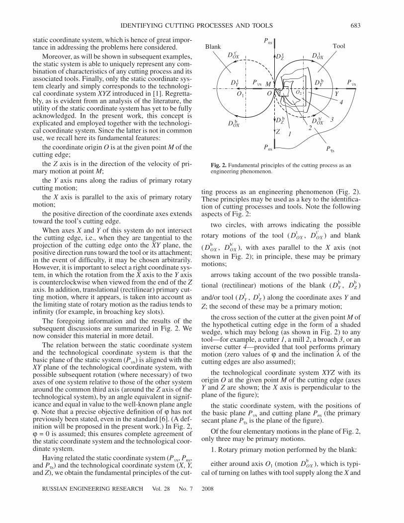
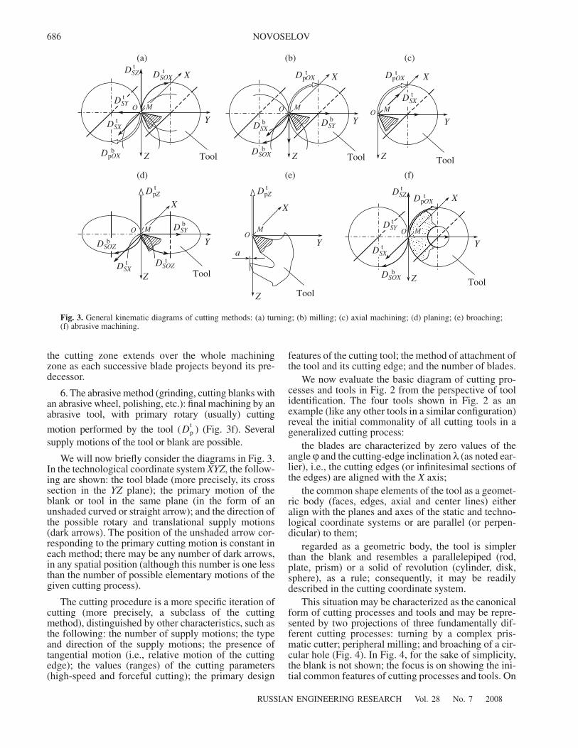
characteristics (Table 1). Their general kinematic dia-grams are shown in Fig. 3.
1. The lathe method (turning): machining by a blade
with rotary primary motion ( ) performed by theblank (Fig. 3a). There are several possible supplymotions. (This is not simply machining of a circularblank by a cutter on a lathe!)
2. The mill method (milling): machining by a blade
with rotary primary cutting motion ( ) performed bythe tool (Fig. 3b). Several supply motions are possible.(This is not simply machining of a prismatic blank by amill on a milling machine!)
3. The axial method (boring, reaming, broaching,etc.): machining with rotary primary cutting motion
related performed by the blank ( ) or tool ( )(Fig. 3c). One supply motion of the blank or tool alongthe axis of rotary motion is possible. (This is not simplyhole formation on a drilling machine!)
4. The plane and chisel method (planing, slotting,etc.): machining by a blade with translational primary
cutting motion performed by the blank ( ) or tool
( ) (Fig. 3d). Several supply motions are possible.(This is not just planing of flat surfaces on a transverse-planing machine!)
5. The broach method (broaching, piercing):machining by a complex blade with translational pri-
mary cutting motion performed by the tool ( ), in aseries of passes (Fig. 3e). There is no supply motion;
Dpb
Dpt
Dpb Dp
t
Dpb
Dpt
Dpt
Table 1. Proposed classification of cutting methods
Cutting method
Primary motion DpPoint of application
of Dp
Number of possible supply motions Ds
Cutting elements
rotary transla-tional blank tool several one none blade grain
Lathe ⊕ – ⊕ – ⊕ – – ⊕ –
Mill ⊕ – – ⊕ ⊕ – – ⊕ –
Axial ⊕ –⊕ �
– ⊕ –⊕ �
� ⊕ � ⊕
Plane and chisel – ⊕⊕ �
⊕ – – ⊕ –� ⊕
Broach – ⊕ – ⊕ – – ⊕ ⊕ –
Abrasive ⊕ – – ⊕ ⊕ – – – ⊕
686
RUSSIAN ENGINEERING RESEARCH Vol. 28 No. 7 2008
NOVOSELOV
the cutting zone extends over the whole machiningzone as each successive blade projects beyond its pre-decessor.
6. The abrasive method (grinding, cutting blanks withan abrasive wheel, polishing, etc.): final machining by anabrasive tool, with primary rotary (usually) cutting
motion performed by the tool ( ) (Fig. 3f). Severalsupply motions of the tool or blank are possible.
We will now briefly consider the diagrams in Fig. 3.In the technological coordinate system XYZ, the follow-ing are shown: the tool blade (more precisely, its crosssection in the YZ plane); the primary motion of theblank or tool in the same plane (in the form of anunshaded curved or straight arrow); and the direction ofthe possible rotary and translational supply motions(dark arrows). The position of the unshaded arrow cor-responding to the primary cutting motion is constant ineach method; there may be any number of dark arrows,in any spatial position (although this number is one lessthan the number of possible elementary motions of thegiven cutting process).
The cutting procedure is a more specific iteration ofcutting (more precisely, a subclass of the cuttingmethod), distinguished by other characteristics, such asthe following: the number of supply motions; the typeand direction of the supply motions; the presence oftangential motion (i.e., relative motion of the cuttingedge); the values (ranges) of the cutting parameters(high-speed and forceful cutting); the primary design
Dpt
features of the cutting tool; the method of attachment ofthe tool and its cutting edge; and the number of blades.
We now evaluate the basic diagram of cutting pro-cesses and tools in Fig. 2 from the perspective of toolidentification. The four tools shown in Fig. 2 as anexample (like any other tools in a similar configuration)reveal the initial commonality of all cutting tools in ageneralized cutting process:
the blades are characterized by zero values of theangle ϕ and the cutting-edge inclination λ (as noted ear-lier), i.e., the cutting edges (or infinitesimal sections ofthe edges) are aligned with the X axis;
the common shape elements of the tool as a geomet-ric body (faces, edges, axial and center lines) eitheralign with the planes and axes of the static and techno-logical coordinate systems or are parallel (or perpen-dicular) to them;
regarded as a geometric body, the tool is simplerthan the blank and resembles a parallelepiped (rod,plate, prism) or a solid of revolution (cylinder, disk,sphere), as a rule; consequently, it may be readilydescribed in the cutting coordinate system.
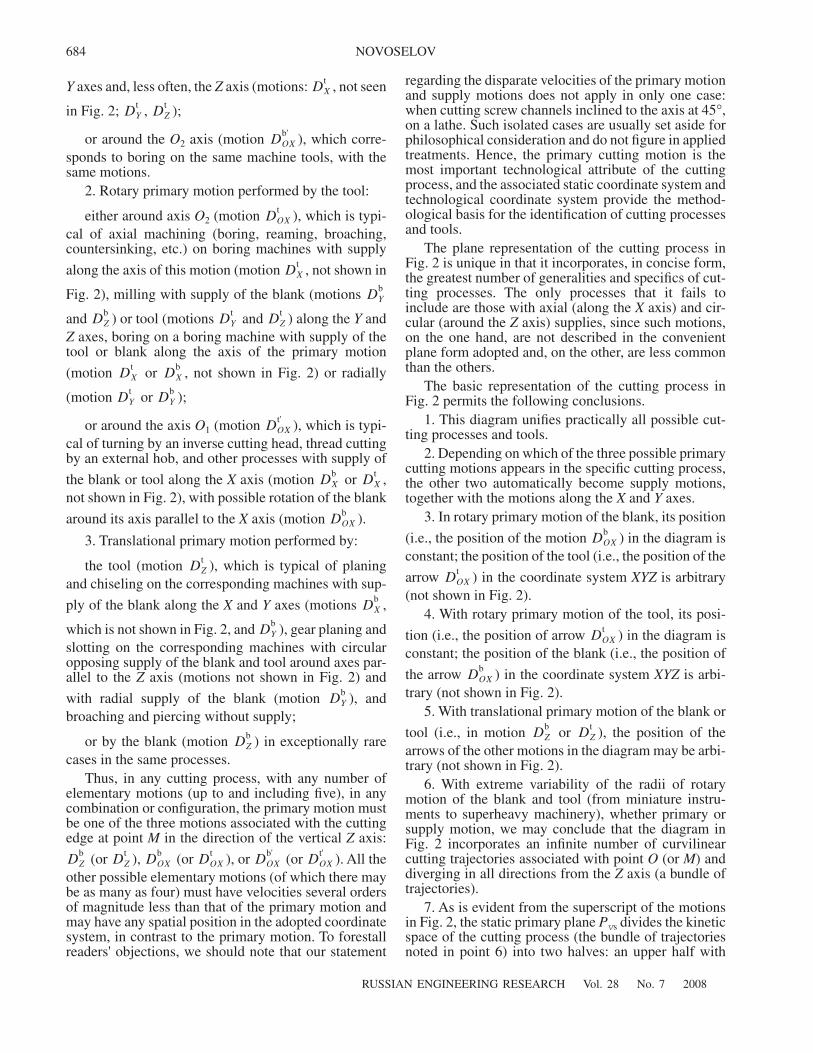
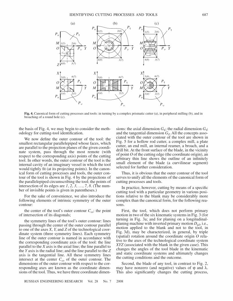
This situation may be characterized as the canonicalform of cutting processes and tools and may be repre-sented by two projections of three fundamentally dif-ferent cutting processes: turning by a complex pris-matic cutter; peripheral milling; and broaching of a cir-cular hole (Fig. 4). In Fig. 4, for the sake of simplicity,the blank is not shown; the focus is on showing the ini-tial common features of cutting processes and tools. On
(a) (b) (c)
(d) (e) (f)
Tool Tool Tool
ToolTool
Tool
Y
Z
Y
Z
O MMO
X X
X
Y Y
X
Z
Y
X
X
Y
Z
Z
Z
O M
MOOMMO
DpOXb DSOX
b
DpOXtDpOX
tDSZt
DSXt
DSYt
DSXb DSY
b
DSXt
DSZt
DpOXt
DSYt
DSXt
DSOXb
DpZt
a
DSYb
DpZt
DSOZt
DSXt
DSOZb
Fig. 3. General kinematic diagrams of cutting methods: (a) turning; (b) milling; (c) axial machining; (d) planing; (e) broaching;(f) abrasive machining.
DSOXt
RUSSIAN ENGINEERING RESEARCH Vol. 28 No. 7 2008
IDENTIFYING CUTTING PROCESSES AND TOOLS 687
the basis of Fig. 4, we may begin to consider the meth-odology for cutting-tool identification.
We now define the outer contour of the tool: thesmallest rectangular parallelepiped whose faces, whichare parallel to the projection planes of the given coordi-nate system, pass through the most remote (withrespect to the corresponding axis) points of the cuttingtool. In other words, the outer contour of the tool is theinternal cavity of an imaginary vessel in which the toolwould tightly fit (at its projecting points). In the canon-ical form of cutting processes and tools, the outer con-tour of the tool is shown in Fig. 4 by the projections ofthe parallelepiped circumscribing the tool; the points ofintersection of its edges are 1, 2, 3, …, 7, 8. (The num-ber of invisible points is given in parentheses.)
For the sake of convenience, we also introduce thefollowing elements of intrinsic symmetry of the outercontour:
the center of the tool’s outer contour Cco: the pointof intersection of its diagonals;
the symmetry lines of the tool’s outer contour: linespassing through the center of the outer contour parallelto one of the axes X, Y, and Z of the technological coor-dinate system (three symmetry lines). Each symmetryline of the outer contour is named in accordance withthe corresponding coordinate axis of the tool: the lineparallel to the X axis is the axial line; the line parallel tothe Y axis is the radial line; and the line parallel to the Zaxis is the tangential line. All these symmetry linesintersect at the center Cco of the outer contour. Thedimensions of the outer contour with respect to the cor-responding axes are known as the coordinate dimen-sions of the tool. Thus, we have three coordinate dimen-
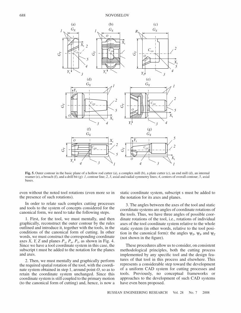
sions: the axial dimension GX; the radial dimension GY;and the tangential dimension GZ. All the concepts asso-ciated with the outer contour of the tool are shown inFig. 5 for a hollow rod cutter, a complex mill, a platecutter, an end mill, an internal reamer, a broach, and adrill bit. At the front surface of the blade, in the vicinityof point O of the cutting edge (the coordinate origin), anarbitrary thin line shows the outline of an infinitelysmall element of the blade (a curvilinear segment)selected for further consideration.
Thus, it is obvious that the outer contour of the toolserves to unify all the elements of the canonical form ofcutting processes and tools.
In practice, however, cutting by means of a specificcutting tool with a particular geometry in various posi-tions relative to the blank may be considerably morecomplex than the canonical form, for the following rea-sons.
First, the tool, which does not perform primarymotion in two of the six kinematic systems in Fig. 3 (forturning in Fig. 3a; and for planing on a longitudinal-planing machine with inverted primary motion DpZ, i.e.,motion applied to the blank and not to the tool, inFig. 3d), may be characterized, in general, by triple(spatial) rotation around the coordinate origin O rela-tive to the axes of the technological coordinate systemXYZ (associated with the blank in the given case). Thischanges the angles of the tool blade in the kinematicand static coordinate systems and ultimately changesthe cutting conditions and the outcome.
Second, the blade of any tool, in contrast to Fig. 2,may have nonzero (and negative) values of ϕ and λ.This also significantly changes the cutting process,
OM
Z
Y
Pn
PτPn
Pτ
Pv
Pv
Pn Pn
Pv
Pτ
Pv
Pτ
X
Y Y
Y
OM
Pn Pτ
Pτ
Y
Pv
Pn
MO
MO
O OM M
X X
1(5) 2(6)
4(8) 3(7)
5(8) 6(7)
2(3)1(4)
CCO
CCO CCO
CCOCCOCCO
4(8) 3(7)
2(6)1(5) 1(5) 2(6)
Pv
3(7)4(8)
(a) (b) (c)
5(8) 5(8) 6(7)6(7)
1(4) 2(3) 2(3)1(4)
Y
Fig. 4. Canonical form of cutting processes and tools: in turning by a complex prismatic cutter (a), in peripheral milling (b), and inbroaching of a round hole (c).
688
RUSSIAN ENGINEERING RESEARCH Vol. 28 No. 7 2008
NOVOSELOV
even without the noted tool rotations (even more so inthe presence of such rotations).
In order to relate such complex cutting processesand tools to the system of concepts considered for thecanonical form, we need to take the following steps.
1. First, for the tool, we must mentally, and thengraphically, reconstruct the outer contour by the rulesoutlined and introduce it, together with the tools, in theconditions of the canonical form of cutting. In otherwords, we must construct the corresponding coordinateaxes X, Y, Z and planes Pv, Pn, Pτ, as shown in Fig. 4.Since we have a tool coordinate system in this case, thesubscript t must be added to the notation for the planesand axes.
2. Then, we must mentally and graphically performthe required spatial rotation of the tool, with the coordi-nate system obtained in step 1, around point O, so as toretain the coordinate system unchanged. Since thiscoordinate system is still coupled to the primary motion(to the canonical form of cutting) and, hence, is now a
static coordinate system, subscript s must be added tothe notation for its axes and planes.
3. The angles between the axes of the tool and staticcoordinate systems are angles of coordinate rotations ofthe tools. Thus, we have three angles of possible coor-dinate rotations of the tool, i.e., rotations of individualaxes of the tool coordinate system relative to the wholestatic system (in other words, relative to the tool posi-tion in the canonical form): the angles ψX, ψY, and ψZ(not shown in the figure).
These procedures allow us to consider, on consistentmethodological principles, both the cutting processimplemented by any specific tool and the design fea-tures of that tool in this process and elsewhere. Thisrepresents a considerable step toward the developmentof a uniform CAD system for cutting processes andtools. Previously, no conceptual frameworks orapproaches to the development of such CAD systemshave even been proposed.
(a) (b) (c)
(d) (e)
GX GX GX
GY
GY
GY
OO
O
CcoCcoCco
Xt
Yt Yt
Xt
Xt
Yt
1
2
3
4
5
1 R
1 1
2 2
5 5
GX
XtXtYt
Yt
GY Cco Cco
CcoCco
3 4 43G
Y
GX
GX GX
(f) (g)
1 1
22
5
5
44 3 3
Yt
Xt
Xt
Yt
O
O
O
O
GY
GY
Fig. 5. Outer contour in the basic plane of a hollow rod cutter (a), a complex mill (b), a plate cutter (c), an end mill (d), an internalreamer (e), a broach (f), and a drill bit (g): 1, contour line; 2, 3, axial and radial symmetry lines; 4, centers of overall contour; 5, axialbases.
45
3
2
RUSSIAN ENGINEERING RESEARCH Vol. 28 No. 7 2008
IDENTIFYING CUTTING PROCESSES AND TOOLS 689
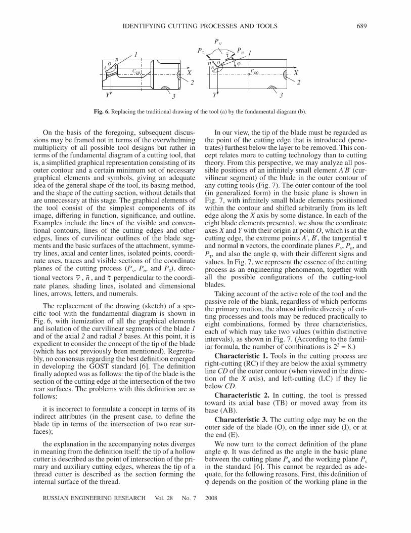
On the basis of the foregoing, subsequent discus-sions may be framed not in terms of the overwhelmingmultiplicity of all possible tool designs but rather interms of the fundamental diagram of a cutting tool, thatis, a simplified graphical representation consisting of itsouter contour and a certain minimum set of necessarygraphical elements and symbols, giving an adequateidea of the general shape of the tool, its basing method,and the shape of the cutting section, without details thatare unnecessary at this stage. The graphical elements ofthe tool consist of the simplest components of itsimage, differing in function, significance, and outline.Examples include the lines of the visible and conven-tional contours, lines of the cutting edges and otheredges, lines of curvilinear outlines of the blade seg-ments and the basic surfaces of the attachment, symme-try lines, axial and center lines, isolated points, coordi-nate axes, traces and visible sections of the coordinateplanes of the cutting process (Pv, Pn, and Pτ), direc-tional vectors , , and perpendicular to the coordi-nate planes, shading lines, isolated and dimensionallines, arrows, letters, and numerals.
The replacement of the drawing (sketch) of a spe-cific tool with the fundamental diagram is shown inFig. 6, with itemization of all the graphical elementsand isolation of the curvilinear segments of the blade 1and of the axial 2 and radial 3 bases. At this point, it isexpedient to consider the concept of the tip of the blade(which has not previously been mentioned). Regretta-bly, no consensus regarding the best definition emergedin developing the GOST standard [6]. The definitionfinally adopted was as follows: the tip of the blade is thesection of the cutting edge at the intersection of the tworear surfaces. The problems with this definition are asfollows:
it is incorrect to formulate a concept in terms of itsindirect attributes (in the present case, to define theblade tip in terms of the intersection of two rear sur-faces);
the explanation in the accompanying notes divergesin meaning from the definition itself: the tip of a hollowcutter is described as the point of intersection of the pri-mary and auxiliary cutting edges, whereas the tip of athread cutter is described as the section forming theinternal surface of the thread.
v n τ
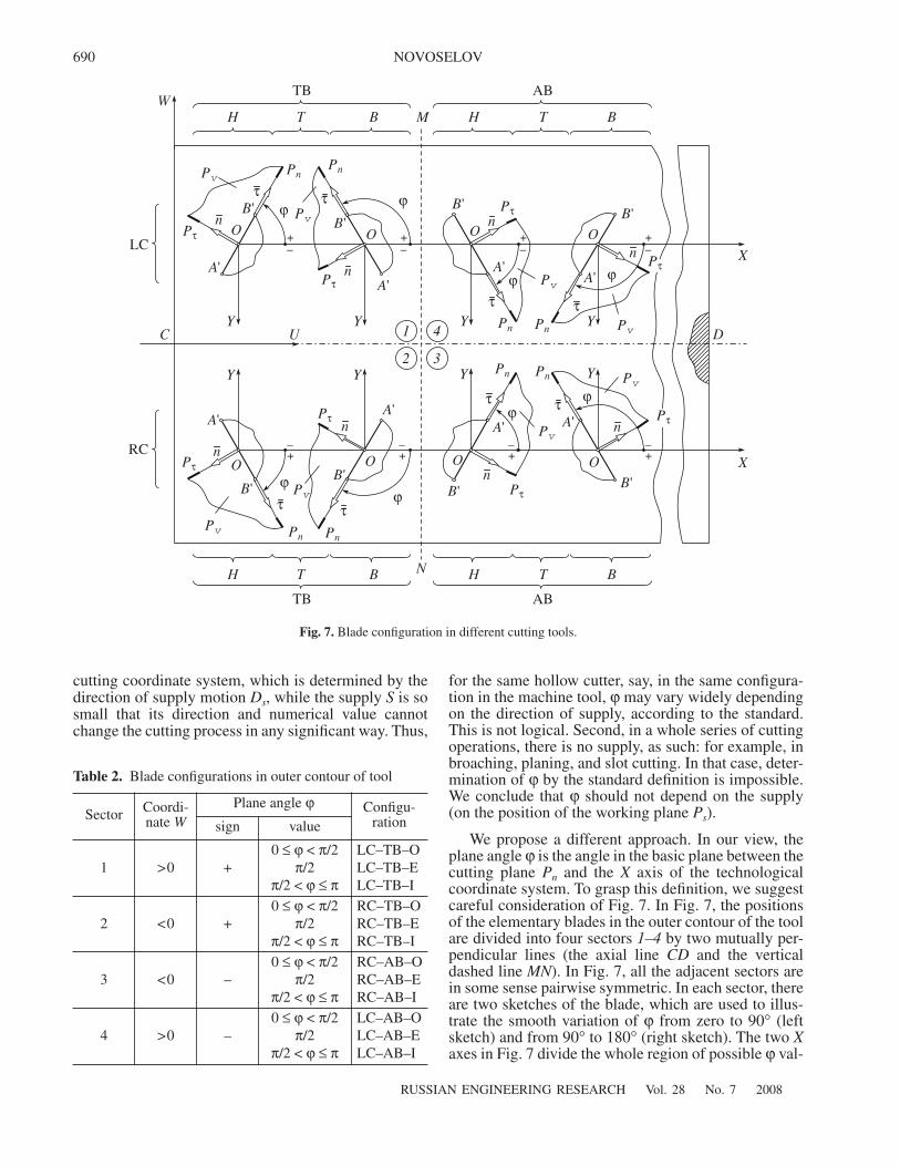
In our view, the tip of the blade must be regarded asthe point of the cutting edge that is introduced (pene-trates) furthest below the layer to be removed. This con-cept relates more to cutting technology than to cuttingtheory. From this perspective, we may analyze all pos-sible positions of an infinitely small element A'B' (cur-vilinear segment) of the blade in the outer contour ofany cutting tools (Fig. 7). The outer contour of the tool(in generalized form) in the basic plane is shown inFig. 7, with infinitely small blade elements positionedwithin the contour and shifted arbitrarily from its leftedge along the X axis by some distance. In each of theeight blade elements presented, we show the coordinateaxes X and Y with their origin at point O, which is at thecutting edge, the extreme points A', B', the tangential tand normal n vectors, the coordinate planes Pv, Pn, andPτ, and also the angle ϕ, with their different signs andvalues. In Fig. 7, we represent the essence of the cuttingprocess as an engineering phenomenon, together withall the possible configurations of the cutting-toolblades.
Taking account of the active role of the tool and thepassive role of the blank, regardless of which performsthe primary motion, the almost infinite diversity of cut-ting processes and tools may be reduced practically toeight combinations, formed by three characteristics,each of which may take two values (within distinctiveintervals), as shown in Fig. 7. (According to the famil-iar formula, the number of combinations is 23 = 8.)
Characteristic 1. Tools in the cutting process areright-cutting (RC) if they are below the axial symmetryline CD of the outer contour (when viewed in the direc-tion of the X axis), and left-cutting (LC) if they liebelow CD.
Characteristic 2. In cutting, the tool is pressedtoward its axial base (TB) or moved away from itsbase (AB).
Characteristic 3. The cutting edge may be on theouter side of the blade (O), on the inner side (I), or atthe end (E).
We now turn to the correct definition of the planeangle ϕ. It was defined as the angle in the basic planebetween the cutting plane Pn and the working plane Psin the standard [6]. This cannot be regarded as ade-quate, for the following reasons. First, this definition ofϕ depends on the position of the working plane in the
AO
B
AO
Pv
Pτ Pnτn ϕ
1
2
X
Y 3 3Y
X
2
1
Cco Cco
Fig. 6. Replacing the traditional drawing of the tool (a) by the fundamental diagram (b).
690
RUSSIAN ENGINEERING RESEARCH Vol. 28 No. 7 2008
NOVOSELOV
cutting coordinate system, which is determined by thedirection of supply motion Ds, while the supply S is sosmall that its direction and numerical value cannotchange the cutting process in any significant way. Thus,
for the same hollow cutter, say, in the same configura-tion in the machine tool, ϕ may vary widely dependingon the direction of supply, according to the standard.This is not logical. Second, in a whole series of cuttingoperations, there is no supply, as such: for example, inbroaching, planing, and slot cutting. In that case, deter-mination of ϕ by the standard definition is impossible.We conclude that ϕ should not depend on the supply(on the position of the working plane Ps).
We propose a different approach. In our view, theplane angle ϕ is the angle in the basic plane between thecutting plane Pn and the X axis of the technologicalcoordinate system. To grasp this definition, we suggestcareful consideration of Fig. 7. In Fig. 7, the positionsof the elementary blades in the outer contour of the toolare divided into four sectors 1–4 by two mutually per-pendicular lines (the axial line CD and the verticaldashed line MN). In Fig. 7, all the adjacent sectors arein some sense pairwise symmetric. In each sector, thereare two sketches of the blade, which are used to illus-trate the smooth variation of ϕ from zero to 90° (leftsketch) and from 90° to 180° (right sketch). The two Xaxes in Fig. 7 divide the whole region of possible ϕ val-
Fig. 7. Blade configuration in different cutting tools.
Table 2. Blade configurations in outer contour of tool
Sector Coordi-nate W
Plane angle ϕ Configu-rationsign value
1 >0 +0 ≤ ϕ < π/2 LC–TB–O
π/2 LC–TB–Eπ/2 < ϕ ≤ π LC–TB–I
2 <0 +0 ≤ ϕ < π/2 RC–TB–O
π/2 RC–TB–Eπ/2 < ϕ ≤ π RC–TB–I
3 <0 –0 ≤ ϕ < π/2 RC–AB–O
π/2 RC–AB–Eπ/2 < ϕ ≤ π RC–AB–I
4 >0 –0 ≤ ϕ < π/2 LC–AB–O
π/2 LC–AB–Eπ/2 < ϕ ≤ π LC–AB–I
+–
+–
+–
+–
1
2
4
3
–+
–+
–+
–+
WH T B
TB AB
H T B
LC
RC
C U D
AB
H T BH T B
TB
PvPn
Pn
Pτn
τ
A'
O
B' ϕ ϕ
Pτ
Pv B'O
A'
B'
O
A'
Pτ
Y Y Y YPn
Pv
O
Pτ
τ
τ
n
nn
τPvPn
A'
B'
X
X
PvYPn
Pτn
O
A'
B'
ϕ ϕ
ϕτϕPv
A'
O
B'n
Pτ
τ
PnYY
A'
OB'
ϕ
nPτ
Pv
Pn
τ
O
B'
A'
ϕ
Pv Pn
τ
Pτn
Y
M
N
RUSSIAN ENGINEERING RESEARCH Vol. 28 No. 7 2008
IDENTIFYING CUTTING PROCESSES AND TOOLS 691
ues into two external regions with positive ϕ (denotedby a plus sign at the X axes) and two internal regionsclose to the line CD, with negative ϕ (denoted by aminus sign at the X axes). Hence, in this diagram, ϕmay vary widely: from 0° to +180°; and from 0° to−180°. If we now introduce the coordinate systemUCW corresponding to the tool’s outer contour (Fig. 7),the composite structure of any tool may be expressed interms of W and ϕ in the form in Table 2 (and ultimatelyin binary code, which falls outside our present scope).
Thus, in the present work, on the basis of consistentconcepts, we have formulated a model expressing thequintessential commonalities of all possible blade-based cutting processes and tools. By adopting differ-ent values and signs (plus or minus) of the key charac-teristics in this model, we may construct any known oras yet unknown cutting processes or tools and investi-gate them by uniform methodological procedures. Thisis the only appropriate means of investigating cuttingprocesses and tools and eventually formulating the cor-responding unified CAD system.
REFERENCES1. Novoselov, Yu.A., Standardization of Cutting Concepts,
Stanki Instrum., 2006, no. 6, pp. 22–26.2. Novoselov, Yu.A., Methodology for the Investigation,
Comprehension, and Teaching of Cutting Theory, Vestn.Mashinostr., 2006, no. 10, pp. 53–57.
3. Granovskii, G.I., Kinematika rezaniya (Kinematics ofCutting), Moscow: Mashgiz, 1976.
4. Tipazh metallorezhushchikh stankov (Classification ofMetal-Cutting Machines), Moscow: NIImash, 1976.
5. Zhuravlev, V.N. and Nikolaeva, O.N., Mashinostroi-tel’nye stali. Spravochnik dlya konstruktorov (Manufac-turing Steels: A Design Handbook), Moscow–Sverd-lovsk: Mashgiz, 196[].
6. GOST (State Standard) 25762-83: Cutting Processes:Terms, Definitions, and Notation for General Concepts,1983.
7. GOST (State Standard) 25761-83: Types of Cutting Pro-cesses: Terms and Definitions for General Concepts,1983.
8. GOST (State Standard) 25751-83: Cutting Tools: Termsand Definitions for General Concepts, 1983.