identification of geometric errors of a mikron 5-axis
TRANSCRIPT

Laboratoire commun de métrologie LNE-Cnam
Fabien VIPREY – LNE – LURPA [email protected]
Personal professional page on LURPA website
Christophe TOURNIER – LURPA
Sylvain LAVERNHE – LURPA
Hichem NOUIRA – LNE
Identification of geometric errors of a MIKRON 5-axis machine-tool using the 3D
hole-bar standard and laser tracer interferometer system
Laboratoire Universitaire en Production Automatisée ENS Cachan
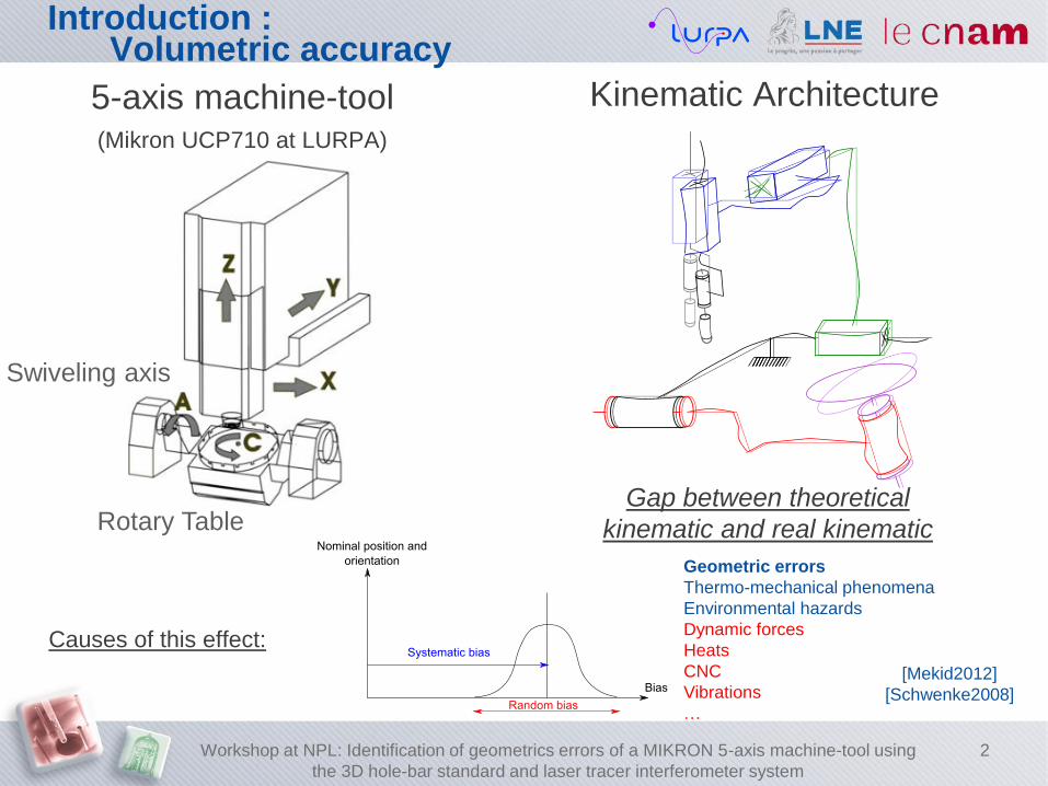
Causes of this effect:
Introduction : Volumetric accuracy
5-axis machine-tool (Mikron UCP710 at LURPA)
Kinematic Architecture
Rotary Table
Swiveling axis
Gap between theoretical
kinematic and real kinematic
Geometric errors
Thermo-mechanical phenomena
Environmental hazards
Dynamic forces
Heats
CNC
Vibrations
…
[Mekid2012]
[Schwenke2008]
Workshop at NPL: Identification of geometrics errors of a MIKRON 5-axis machine-tool using
the 3D hole-bar standard and laser tracer interferometer system
2

Introduction : Volumetric accuracy
International standard [ISO230-1,2012]:
The aim of this study is to develop a material standard to 21 errors evaluation [Bourdet87]:
- Usable on CMM, 3 or 5 machine-tool, by on-line measurement with accuracy
of the results
- With large field of its application: Metrology room or Manufacturing shop
- With constraint of time: Adjustment + Measurement < 10 + 15 min
Workshop at NPL: Identification of geometrics errors of a MIKRON 5-axis machine-tool using
the 3D hole-bar standard and laser tracer interferometer system
3
Outline
Literature review
Stage of development
Design of pattern: Hole Bar
Technical attributes
Mesurement process
Calibration and strategy of error measurement with hole bar
Evaluation of 21 geometric errors: Hole bar
Evaluation of 21 geometric errors: Laser Tracer
Results
Geometric errors: Laser Tracer
Geometric errors: Hole bar
Conclusion and further works
Workshop at NPL: Identification of geometrics errors of a MIKRON 5-axis machine-tool using
the 3D hole-bar standard and laser tracer interferometer system
4

Conscious decision: Development of bar with pattern which allow to maximize ,
minimizing maintenance downtime
Reference
Metrology
room and
Shop
= Evaluated errors/Number
of standard position
Time of adjustment
and measurement
Accuracy and size
of error mapping
1 [Trapet1991]
[Bringmann2009] /
/
21/4 = 5,25
21/5 = 4,2 /
/
/
/
2 [Zhang1991]
[Lim2005] /
/
21/?
21/17 = 1,23 ?
/
/?
/
3 [ISO 230-1] / ≤ 1 / /
4 [Schwenke2005]
[Chen1999] /
/
21/6 = 3,5
21/3 = 7 /
?/
/
/?
Introduction : Literature review
Hole plate
Conventional method
2 4
3 Ball plate Ball Bar
1 Hole Bar
Laser Interferometry (On-line measurement)
Workshop at NPL: Identification of geometrics errors of a MIKRON 5-axis machine-tool using
the 3D hole-bar standard and laser tracer interferometer system
5

Outline
Literature review
Stage of development
Design of pattern: Hole Bar
Technical attributes
Mesurement process
Calibration and strategy of error measurement with hole bar
Evaluation of 21 geometric errors: Hole bar
Evaluation of 21 geometric errors: Laser Tracer
Results
Geometric errors: Laser Tracer
Geometric errors: Hole bar
Conclusion and further works
Workshop at NPL: Identification of geometrics errors of a
MIKRON 5-axis machine-tool using the 3D hole-bar standard
and laser tracer interferometer system
6
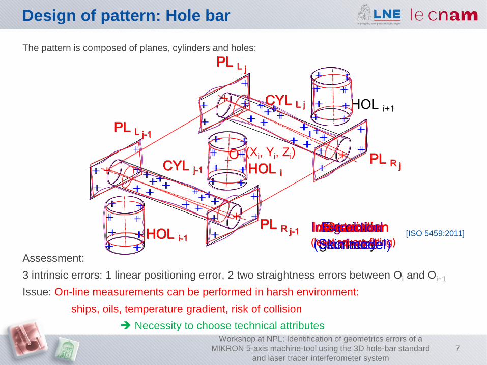
Design of pattern: Hole bar
The pattern is composed of planes, cylinders and holes:
Assessment:
3 intrinsic errors: 1 linear positioning error, 2 two straightness errors between Oi and Oi+1
Issue: On-line measurements can be performed in harsh environment:
ships, oils, temperature gradient, risk of collision
Necessity to choose technical attributes
[ISO 5459:2011]
Workshop at NPL: Identification of geometrics errors of a
MIKRON 5-axis machine-tool using the 3D hole-bar standard
and laser tracer interferometer system
7
(Xi, Yi, Zi)

Solution:
- All geometry entity and
number of pattern
can be parameterized
Technical attributes
Material Proposed
geometry
Assembly on
CMM or MT
Constraints:
- Harsh environment
- Gradient of temperature
- Risk of collision
Solution: INVAR
- CTE < 1,5 µm.K-1.m-1
- Ni-Fe alloy has a better
toughness and a less
brittleness than ceramic
engineering or Zerodur
Constraints:
- Harsh environment
- Risk of collision
- Accessibility
- Mistake-proofing
Constraints:
- Consider all admissible
positionning
- Minimize distortion of hole bar
Solution:
- Assembly with modular
inspection equipment system
L
Metrology
room/Shop
= Evaluated error/Number
of standard position
Time of adjustment
and measurement
Accuracy/size of
error mapping
Hole bar / ? / ?
Workshop at NPL: Identification of geometrics errors of a MIKRON 5-axis machine-tool using
the 3D hole-bar standard and laser tracer interferometer system
8
Outline
Literature review
Stage of development
Design of pattern: Hole Bar
Technical attributes
Mesurement process
Calibration and strategy of error measurement with hole bar
Evaluation of 21 geometric errors: Hole bar
Evaluation of 21 geometric errors: Laser Tracer
Results
Geometric errors: Laser Tracer
Geometric errors: Hole bar
Conclusion and further works
Workshop at NPL: Identification of geometrics errors of a MIKRON 5-axis machine-tool using
the 3D hole-bar standard and laser tracer interferometer system
9

Calibration of hole bar
10
Calibration was performed on CMM by reversal method [Evans1996]
Hole bar (no reversal)
Hole bar (after reversal)
Workshop at NPL: Identification of geometrics errors of a MIKRON 5-axis machine-tool using
the 3D hole-bar standard and laser tracer interferometer system
Linear positioning error motion of holes
Straightness error motion of holes
in Y-direction
Straightness error motion of holes
in Z-direction

Strategy of error measurement with hole bar
Real time
probing
Developed end user interface
F=33,33 kHz
T=30 µs
Resolution = 10 nm
U(k=2) RMP600 = 0,25 µm
Udelay max at 240mm/min = 0,47µm
Probing
trajectory
Vf rapid = 1000 mm/min
Vf probing = 240 mm/min
Mikron UCP710
Workshop at NPL: Identification of geometrics errors of a MIKRON 5-axis machine-tool using
the 3D hole-bar standard and laser tracer interferometer system
11

Evaluation of 21 geometric errors: Hole bar
Assessment:
11 positions of hole bar 21 errors in 3-axis machine-tool;
7 positions of hole bar 21 errors in 3-axis machine-tool + A,C axis (5-axis positional machine).
+ -
+ -
+ -
Eax(X), Ebx(X)
Exx(X), Eyx(X), Ezx(X)
Ecx(X) (Eax(X))
differential
straightness
measurement
[ISO 230-1]
differential
straightness
measurement
[ISO 230-1]
Calibration
Metrology
room/Shop
= Evaluated error/Number
of standard position
Time of adjustment
and measurement
Accuracy/size of
error mapping
Hole bar, 3-axis MT
Hole bar , 3-axis + (A,C) / 21/11 = 1,91
21/7 = 3 / ?
Calibration
Workshop at NPL: Identification of geometrics errors of a MIKRON 5-axis machine-tool using
the 3D hole-bar standard and laser tracer interferometer system
12
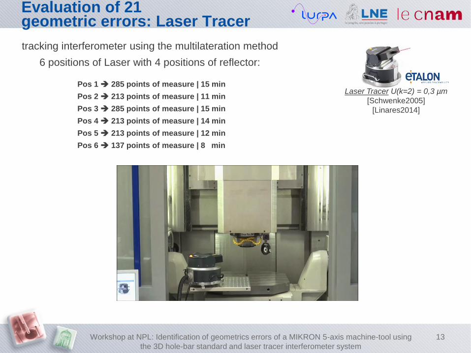
Evaluation of 21 geometric errors: Laser Tracer
tracking interferometer using the multilateration method
6 positions of Laser with 4 positions of reflector:
Pos 1 285 points of measure | 15 min
Pos 2 213 points of measure | 11 min
Pos 3 285 points of measure | 15 min
Pos 4 213 points of measure | 14 min
Pos 5 213 points of measure | 12 min
Pos 6 137 points of measure | 8 min
Laser Tracer U(k=2) = 0,3 µm
[Schwenke2005]
[Linares2014]
Workshop at NPL: Identification of geometrics errors of a MIKRON 5-axis machine-tool using
the 3D hole-bar standard and laser tracer interferometer system
13
Outline
Literature review
Stage of development
Design of pattern: Hole Bar
Technical attributes
Mesurement process
Calibration and strategy of error measurement with hole bar
Evaluation of 21 geometric errors: Hole bar
Evaluation of 21 geometric errors: Laser Tracer
Results
Geometric errors: Laser Tracer
Geometric errors: Hole bar
Conclusion and further works
Workshop at NPL: Identification of geometrics errors of a MIKRON 5-axis machine-tool using
the 3D hole-bar standard and laser tracer interferometer system
14
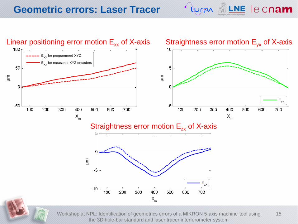
Geometric errors: Laser Tracer
Xm
µm
Linear positioning error motion of X-axis
EXX
for programmed XYZ
EXX
for measured XYZ encoders
Xm
µm
Straightness errors motion of X-axis
EYX
Xm
µm
Straightness errors motion of X-axis
EZX
Xm
µm
Linear positioning error motion of X-axis
EXX
for programmed XYZ
EXX
for measured XYZ encoders
Xm
µm
Straightness errors motion of X-axis
EYX
Xm
µm
Straightness errors motion of X-axis
EZX
Workshop at NPL: Identification of geometrics errors of a MIKRON 5-axis machine-tool using
the 3D hole-bar standard and laser tracer interferometer system
15
Linear positioning error motion Exx of X-axis Straightness error motion Eyx of X-axis
Straightness error motion Ezx of X-axis

Xm
µm
Linear positioning error motion of X-axis
Exx for X-programmed
Exx for X-encoders
Exx enc - Exx prog
Siemens MSECX
Xm
µm
Residu between Exx enc - Exx prog
and Siemens MSECX
Ymµm
Linear positioning error motion of Y-axis
Eyy for Y-programmed
Eyy for Y-encoders
Eyy enc - Eyy prog
Siemens MSECY
Ym
µm
Residu between Eyy enc - Eyy prog
and Siemens MSECY
Zm
µm
Linear positioning error motion of Z-axis
Ezz for Z-programmed
Ezz for Z-encoders
Ezz enc - Ezz prog
Siemens MSECX
Zm
µm
Residu between Ezz enc - Ezz prog
and Siemens MSECZ
Geometric errors: Laser Tracer
Workshop at NPL: Identification of geometrics errors of a MIKRON 5-axis machine-tool using
the 3D hole-bar standard and laser tracer interferometer system
16
Linear positioning error motion EXX of X-axis Linear positioning error motion EYY of Y-axis Linear positioning error motion EZZ of Z-axis
Residu between EXX enc – EXX prog
and Siemens MSECX
Residu between EYY enc – EYY prog
and Siemens MSECY
Residu between EZZ enc – EZZ prog
and Siemens MSECZ
Xm
µm
Linear positioning error motion Exx of X-axis
1
2
3
4
5
Xm
µm
Straightness error motion Eyx of X-axis
1
2
3
4
5
Xm
µm
Straightness error motion Ezx of X-axis
1
2
3
4
5
Xm
µm
Linear positioning error motion Exx of X-axis
1
2
3
4
5
Xm
µm
Straightness error motion Eyx of X-axis
1
2
3
4
5
Xm
µm
Straightness error motion Ezx of X-axis
1
2
3
4
5
17 Workshop at NPL: Identification of geometrics errors of a MIKRON 5-axis machine-tool using
the 3D hole-bar standard and laser tracer interferometer system
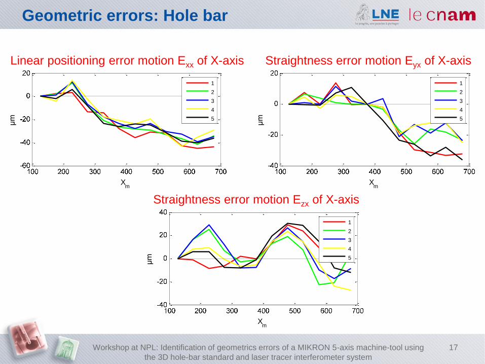
Geometric errors: Hole bar
Linear positioning error motion Exx of X-axis Straightness error motion Eyx of X-axis
Straightness error motion Ezx of X-axis

Outline
Literature review
Stage of development
Design of pattern: Hole Bar
Technical attributes
Mesurement process
Calibration and strategy of error measurement with hole bar
Evaluation of 21 geometric errors: Hole bar
Evaluation of 21 geometric errors: Laser Tracer
Results
Geometric errors: Laser Tracer
Geometric errors: Hole bar
Conclusion and further works
Workshop at NPL: Identification of geometrics errors of a MIKRON 5-axis machine-tool using
the 3D hole-bar standard and laser tracer interferometer system
18
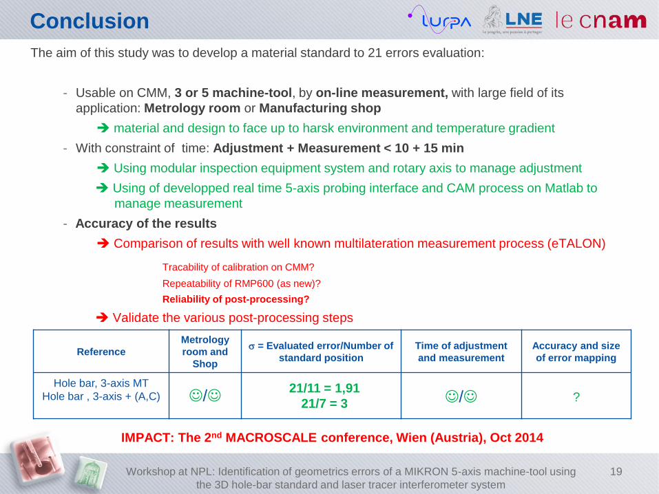
Conclusion
The aim of this study was to develop a material standard to 21 errors evaluation:
- Usable on CMM, 3 or 5 machine-tool, by on-line measurement, with large field of its
application: Metrology room or Manufacturing shop
material and design to face up to harsk environment and temperature gradient
- With constraint of time: Adjustment + Measurement < 10 + 15 min
Using modular inspection equipment system and rotary axis to manage adjustment
Using of developped real time 5-axis probing interface and CAM process on Matlab to
manage measurement
- Accuracy of the results
Comparison of results with well known multilateration measurement process (eTALON)
Tracability of calibration on CMM?
Repeatability of RMP600 (as new)?
Reliability of post-processing?
Validate the various post-processing steps
IMPACT: The 2nd MACROSCALE conference, Wien (Austria), Oct 2014
Reference
Metrology
room and
Shop
= Evaluated error/Number of
standard position
Time of adjustment
and measurement
Accuracy and size
of error mapping
Hole bar, 3-axis MT
Hole bar , 3-axis + (A,C)
/
21/11 = 1,91
21/7 = 3 / ?
Workshop at NPL: Identification of geometrics errors of a MIKRON 5-axis machine-tool using
the 3D hole-bar standard and laser tracer interferometer system
19
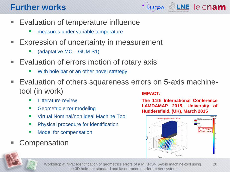
Further works
Evaluation of temperature influence measures under variable temperature
Expression of uncertainty in measurement (adaptative MC – GUM S1)
Evaluation of errors motion of rotary axis With hole bar or an other novel strategy
Evaluation of others squareness errors on 5-axis machine-
tool (in work) Litterature review
Geometric error modeling
Virtual Nominal/non ideal Machine Tool
Physical procedure for identification
Model for compensation
Compensation
Workshop at NPL: Identification of geometrics errors of a MIKRON 5-axis machine-tool using
the 3D hole-bar standard and laser tracer interferometer system
20
IMPACT:
The 11th International Conference
LAMDAMAP 2015, University of
Huddersfield, (UK), March 2015

Laboratoire commun de métrologie LNE-Cnam
Thank you for your attention!
The authors sincerely thank the EMRP organization. The EMRP is jointly funded
by the EMRP participating countries within EURAMET and the European Union
(IND62: JRP-TIM)
Laboratoire Universitaire en Production Automatisée ENS Cachan
Fabien VIPREY – LNE – LURPA [email protected]
Personal professional page on LURPA website
Christophe TOURNIER – LURPA
Sylvain LAVERNHE – LURPA
Hichem NOUIRA – LNE

References
[Bourdet, 1987] Bourdet (1987). Contribution a la Mesure Tridimensionnelle : Modèle d’identification geométrique des surfaces,
Métrologie fonctionnelle des pièces mécaniques, Correction geométrique des machines a mesurer tridimensionnelles. Doctorat
d’etat et sciences physiques, Univ. NANCY 1.
[Bringmann2009] B. Bringmann, W. Knapp, Machine tool calibration: Geometric test uncertainty depends on machine tool
performance, Precision Engineering, Vol. 33, Issue 4, 2009, pp. 524-529
[Chen1999] Jenq Shyong Chen et al., Geometric error calibration of multi-axis machines using an auto-alignment laser
interferometer, Precision Engineering, Vol. 23, Issue 4, 1999, pp. 243-252
[Evans1996] Chris J. Evans et al., Self-Calibration: Reversal, Redundancy, Error Separation, and ‘Absolute Testing’, CIRP
Annals - Manufacturing Technology, Vol. 45, Issue 2, 1996, pp. 617-634
[ISO 230-1] ISO 230-1:2012, Test code for machine tools -- Part 1: Geometric accuracy of machines operating under no-load or
quasi-static conditions
[ISO 5459:2011] ISO 5459:2011, Geometrical product specifications (GPS) -- Geometrical tolerancing -- Datums and datum
systems
[Lim2005] C.K Lim, M. Burdekin, Rapid volumetric calibration of coordinate measuring machines using a hole bar artefact,
Proceedings of the Institution of Mechanical Engineers. Part B. Journal of engineering manufacture, 2002, Vol. 216, Issue 8,
2002, pp. 1083-1093
[Linares2014] Jean-Marc Linares et al., Impact of measurement procedure when error mapping and compensating a small CNC
machine using a multilateration laser interferometer, Precision Engineering, Vol. 38, Issue 3, 2014, pp 578-588
[Mekid2012] S. Mekid, T. Ogedengbe, A review of machine tool accuracy enhancement through error compensation in serial and
parallel kinematic machines, International Journal of Precision Technology, Vol. 1, Issue 3, 2010, pp. 251-286
[Schwenke2005] H. Schwenke et al., Error mapping of CMMs and machine tools by a single tracking interferometer, CIRP Annals
- Manufacturing Technology, Vol. 54, Issue 1, 2005, pp. 475-478
[Schwenke2008] H. Schwenke et al., Geometric error measurement and compensation of machines—An update, CIRP Annals -
Manufacturing Technology, Vol. 57, Issue 2, 2008, pp. 660-675
[Trapet1991] E Trapet, F Wäldele, A reference object based method to determine the parametric error components of coordinate
measuring machines and machine tools, Measurement, Vol. 9, Issue 1, 1991, pp. 17-22
[Zhang1991] G.X. Zhang, Y.F. Zang, A Method for Machine Geometry Calibration Using 1-D Ball Array, CIRP Annals -
Manufacturing Technology, Vol. 40, Issue 1, 1991, pp. 519-522
Workshop at NPL: Identification of geometrics errors of a MIKRON 5-axis machine-tool using
the 3D hole-bar standard and laser tracer interferometer system
22