iconnect control system installation manual line... · tamper switch: n.c. operating temperature:...
TRANSCRIPT


ii
iConnect Control System Installation Manual Catalog Number: ZI0547G (06/10) All data is subject to change without prior notice. Hereby, Electronics Line 3000 Ltd. declares that this control system is in compliance with the essential requirements and other relevant provisions of Directive 1999/5/EC. Copyright © 2010 Electronics Line 3000 Ltd. All rights reserved

iii
Table of Contents
1. Introduction ..................................................................................................................................1 1.1. Documentation Conventions ............................................................................................................1 1.2. Specifications ................................................................................................................................2 1.3. System Overview ...........................................................................................................................2 1.4. Hardware Layout............................................................................................................................4
2. System Installation .......................................................................................................................9 2.1. Pre-Installation Planning .................................................................................................................9 2.2. Installation Procedure ................................................................................................................... 10 2.3. Back Tamper ............................................................................................................................... 13 2.4. Installing Hardwire LCD Keypads .................................................................................................... 13 2.5. Internet Communication Setup (Not Relevant to PSTN-only Configuration) ........................................... 14
3. Basic System Operation...............................................................................................................16 3.1. Front Panel Layout (LCD Top Cover) ............................................................................................... 16 3.2. Front Panel System Status LEDs (LCD Top Cover) ............................................................................. 16 3.3. Front Panel Keypad and Hardwire LCD Keypad ................................................................................. 17 3.4. LCD Display................................................................................................................................. 18 3.5. Front Panel Layout (LED Top Cover)................................................................................................ 19 3.6. System Status LEDs (LED Top Cover).............................................................................................. 20 3.7. Arming Status LEDs (LED Top Cover) .............................................................................................. 20 3.8. Front Panel Keypad (LED Top Cover)............................................................................................... 20 3.9. Audible Notification ...................................................................................................................... 21 3.10. Arming and Disarming – Unpartitioned Systems ............................................................................... 22 3.11. Arming/Disarming – Partitioned Systems......................................................................................... 24 3.12. Additional Arming Options ............................................................................................................. 26
4. Advanced System Operation........................................................................................................28 4.1. Menu Navigation .......................................................................................................................... 28 4.2. Cancel Report .............................................................................................................................. 28 4.3. Zone Bypassing/Unbypassing......................................................................................................... 29 4.4. User Codes.................................................................................................................................. 29 4.5. Follow-Me ................................................................................................................................... 31 4.6. Speed Dial Numbers ..................................................................................................................... 31 4.7. Event Log ................................................................................................................................... 31 4.8. Service Menu............................................................................................................................... 32
5. Telecontrol and Two-Way Audio ..................................................................................................37 5.1. Incoming Calls............................................................................................................................. 37 5.2. Outgoing Calls ............................................................................................................................. 39
6. Home Automation and PGM Control.............................................................................................41 6.1. Keypad Control ............................................................................................................................ 41 6.2. Keyfob Control............................................................................................................................. 41 6.3. Telephone Control ........................................................................................................................ 41 6.4. Scheduling (not relevant to PGM) ................................................................................................... 42
7. Devices........................................................................................................................................43 7.1. Device Descriptors ....................................................................................................................... 43 7.2. Wireless Devices .......................................................................................................................... 43 7.3. Zones......................................................................................................................................... 44 7.4. Keyfobs ...................................................................................................................................... 48 7.5. Keypads ..................................................................................................................................... 49

iv
7.6. Repeaters....................................................................................................................................50 7.7. Wireless Siren..............................................................................................................................50 7.8. Smartkeys...................................................................................................................................51
8. Entry/Exit Timers and System Tones .......................................................................................... 53 8.1. Entry/Exit Delay ...........................................................................................................................53 8.2. Arm on Exit .................................................................................................................................53 8.3. Supplementary Entry Delay............................................................................................................53 8.4. Entry Deviation ............................................................................................................................53 8.5. Arming Tones...............................................................................................................................53 8.6. Home Automation Tones................................................................................................................54 8.7. System Trouble Tones...................................................................................................................54 8.8. Tones Options ..............................................................................................................................55
9. System Options........................................................................................................................... 56 9.1. Swinger Setting............................................................................................................................56 9.2. Code Lockout ...............................................................................................................................56 9.3. Arm/Disarm Options .....................................................................................................................56 9.4. Panic Alarm .................................................................................................................................57 9.5. AC Loss Delay ..............................................................................................................................57 9.6. Display Options ............................................................................................................................58 9.7. PGM Output Options......................................................................................................................59 9.8. Guard Code .................................................................................................................................60 9.9. "No Arm" Indication ......................................................................................................................61 9.10. Jamming Detection .......................................................................................................................61 9.11. "No Motion" Time .........................................................................................................................61 9.12. Microphone/Speaker Options..........................................................................................................61 9.13. Vocal Messages ............................................................................................................................61 9.14. Installer Access ............................................................................................................................62 9.15. Auto Log View (for future use)........................................................................................................62 9.16. Daylight Savings ..........................................................................................................................62 9.17. Standard Type .............................................................................................................................62 9.18. Entry/Exit Trouble ........................................................................................................................63 9.19. Report Fail Trouble .......................................................................................................................63 9.20. Immediate Arming from WUApp .....................................................................................................63 9.21. Battery Type................................................................................................................................64 9.22. Partition ......................................................................................................................................64 9.23. T014A Standard ...........................................................................................................................64
10. Communications ......................................................................................................................... 65 10.1. System Reporting .........................................................................................................................65 10.2. Report Cycles...............................................................................................................................66 10.3. Vocal Message Dialer ....................................................................................................................67 10.4. Remote Programming....................................................................................................................68 10.5. Service Call .................................................................................................................................70 10.6. Communications Options ...............................................................................................................70 10.7. GSM Options (Not relevant to PSTN only or Ethernet configuration) .....................................................72 10.8. TWA Event Report Options .............................................................................................................74 10.9. Event Options for Central Station Reporting......................................................................................75 10.10. Vocal Message Dialer Event Options.............................................................................................75
11. Internet Options (Relevant to Ethernet/GPRS & ELAS Configuration) .............................................. 77 11.1. ELAS Connection Parameters..........................................................................................................77 11.2. Control System Parameters............................................................................................................77 11.3. GPRS Network Parameters .............................................................................................................77
v
11.4. LAN Network Parameters............................................................................................................... 78
12. Home Automation Programming .................................................................................................80 12.1. X10 Overview .............................................................................................................................. 80 12.2. HA Units ..................................................................................................................................... 80 12.3. House Code................................................................................................................................. 82 12.4. HA Control .................................................................................................................................. 82
13. System Initialization ...................................................................................................................83 13.1. Initialization ................................................................................................................................ 83 13.2. Default Program Restore ............................................................................................................... 83 13.3. Clear User Codes ......................................................................................................................... 83 13.4. Clear Wireless Transmitters ........................................................................................................... 83 13.5. Find Modules ............................................................................................................................... 83
Appendix A: Menu Structure...................................................................................................................84
Appendix B: Transmitter Installation......................................................................................................91 iConnect PIR Sensors (EL-2745/2745PI)..................................................................................................... 91 PIR Sensors (EL-2600/EL-2600PI/EL-2645/EL-2645PI)................................................................................. 94 Magnetic Contact (EL-2601) ..................................................................................................................... 97 Universal Transmitter (EL-2602) ............................................................................................................... 98 Glassbreak Sensor (EL-2606).................................................................................................................. 100 Smoke Detector (EL-2603) ..................................................................................................................... 103 Smoke Detector (EL-2630EN) ................................................................................................................. 103 Keyfobs (EL-2611/EL-2714).................................................................................................................... 109 Wireless Terminal (EL-2724)................................................................................................................... 109 Wireless Keypad (EL-2640)..................................................................................................................... 111 Flood Sensor (EL-2661) ......................................................................................................................... 112 Repeater (EL-2635)............................................................................................................................... 113 Transmitter Specifications ...................................................................................................................... 117
Appendix C: Web User Application........................................................................................................119 Options Available from Main Page............................................................................................................ 121
Appendix D: Installing IP Cameras (Relevant to GPRS/Ethernet & ELAS Configuration) ......................127
Appendix E: Event Table .......................................................................................................................130
Appendix F: Zone Types........................................................................................................................133


1 Introduction
iConnect Installation Manual
1
1. Introduction This manual is designed to help you install the iConnect Control System1. We strongly urge you to read through this manual, in its entirety, before beginning the installation process so that you can best understand all that this security system has to offer. This manual is not intended for end user use. End users are encouraged to read the user manual provided with the system. If you have any questions concerning any of the procedures described in this manual please contact Electronics Line 3000 Ltd. at (+972-3) 918-1333.
1.1. Documentation Conventions Throughout the manual, we have tried to include all of the operating and programming functions using a similar structure and order as they appear in the menu. A detailed explanation of how to navigate the Control System’s menu is included in Menu Navigation. In order to simplify the procedures that appear in the rest of this manual, the following conventions are used:
Item… Description…
Select… Use the arrow keys to scroll through the options and press .
From the Event Log Menu, select Clear Log.
Enter the main menu by pressing and entering your user code. Using the arrow keys, navigate until you reach Event Log and press . Using the arrow keys, navigate until you reach Clear Log and press .
From the Service menu, select Set Time/Date, Set Date.
The same as above only this time you are navigating through three menu levels.
[7012] The shortcut to a specific menu item from the main menu. In this case, this is the shortcut for Set Date. These appear in the procedures as an additional aid to menu navigation.
[#5] A shortcut to a specific item in a sub-menu. For example, [#5] is the shortcut to Bell enable disable in the sub-menu that is opened once you have selected the sensor you want to program.
The symbol on a key that appears on the keypad
5. Interface Test The text that actually appears on the LCD display (bold).
Note: Due to the occurrence
Important note, please pay attention.
Caution: The iConnect Control System is …
Caution: description of a potentially hazardous situation.
Warning Do not test with flame!
Warning: description of a potentially hazardous situation that is a threat to human life.
EN Note – restrictions and settings demanded by the standard EN 50131-1
Table 1-1: Documentation Conventions
1 The terms Control System, Control Panel, and CP refer to the same notion.

1 Introduction
iConnect Installation Manual 2
1.2. Specifications General Zones: 32 wireless zones (1 transmitter per zone), 1 hardwire zone (Zone 33), or zones 1 – 8 as wired zones, zones 9 – 32 as wireless and 1 hardwire zone (Zone 33). Wireless Keyfobs: 19 (Controlled or Non-controlled) Wireless Keypads: up to 4, including one way/EL-2640/EL-2724 Hardwire LCD Keypads: 3 Repeaters: 4 Smartkeys: 16 (Controlled or Non-controlled) Wireless Siren: 1 (1-way or 2-way) User Codes: 32 Arming Methods: Full, Part or Perimeter; for partitioned systems: Full, Partition 1, Partition 2 Event Log: 1022 event capacity, time and date stamped Weight: 1.350g Dimensions: 270 x 222 x 50mm Communications Event Reporting Accounts: up to 6, including Central Station, Follow-Me, and Voice . Telephone Numbers: 6 event reporting accounts, RP Callback, Service Call, 5 speed dial numbers. Communication Interface Options: GPRS, GSM, PSTN, Ethernet. Home Automation Control Medium: Power-line carrier Protocol: X10 HA Units: 16 individually addressed
Receiver Type: Super-heterodyne, fixed frequency Frequency: 418MHz, 868.35, 433.92 (optional). Data Encryption: SecuriCode™ Electrical* Power Input: 230VAC, 50Hz AC Current Consumption (GPRS Configuration): 30mA (alarm), 17mA (standby) AC Current Consumption (Ethernet Configuration): 35mA (alarm), 17mA (standby) DC Current Consumption (GPRS Configuration): 280mA (alarm), 130mA (standby) DC Current Consumption (Ethernet Configuration): 330mA (alarm), 135mA (standby) Maximum Auxiliary Output Current Rating : 50mA Battery low: below 7.15V Backup Battery Pack: 1 x 7.2V/1.8Ah Part No. BT5780 (6 x 1.2V Ni-MH rechargeable cells, size AA) The maximum charging current for the BT-5780 is 5.4A
For EN-50131 standard, 1.8Ah battery is mandatory.
Fuse Ratings: 63mA/250V for 230VAC – Part No. EF1063, PGM Relay Output Contact Rating: 100mA (max. load) Built-in Siren: 93dB @ 10ft Tamper Switch: N.C. Operating Temperature: 0-60°C /32-140°F
Complies with EN-50131-3 Grade 2 Class II Power Supply Type A
1.3. System Overview The iConnect Control System is a full-featured wireless control system that is expected to provide a solution to the needs of most residential installations. This system has been developed based upon a design concept geared towards easy installation and use. With this in mind, the user interface is based on a simple, menu-driven model that suits the essential requirements of both the user and installer alike. You can program the iConnect Control System on-site using the on-board LCD keypad or PC, or off-site via a PC using local programming option of the Remote Programmer. The system offers GPRS and Ethernet network connectivity, providing high-speed central station reporting via a GPRS or Ethernet interface. The Electronics Line Application Server (ELAS) handles all communication between the system, service providers and web users enabling monitoring and control to be performed via the Web. Backup communication is carried out by Communication module via PSTN or GSM. Central station communication and remote parameters programming and maintenance employ Ethernet, GPRS, GSM or standard PSTN communication. SMS messaging provides an innovative method used for both central station and Follow-Me user monitoring. Additionally, SMS messages can be sent to the Control System enabling the user to send commands to the system from anywhere on the planet. The Control System’s home automation capabilities provide a wealth of features. The Home Automation module interfaces with X10 units over the powerline network and grants the user appliance control via a number of different media.
* * The measurements are with fully charged battery. AC current was measured on fuse F1 and DC current was measured on fuse F2.
Power connection to the unit should be according to the national electrical code for permanent installation.
The power supply should be fed from a readily accessible disconnect device. If the unit is permanently wired to the mains power, use a 2-pole disconnect device (15A max.) and the wires should be min. 0.75mm2 in a conduit of at least 16mm. If the mains power is connected with a plug, the plug should be indicated as the disconnecting device and the socket shall be max. 2m from the Control System. Batteries shall be provided by a distributor and replaced by authorized service personnel. The backup battery pack should be replaced every five years. Batteries should be stored in a cool, dry place.
!

1 Introduction
iConnect Installation Manual
3
Figure 1-1 shows the components that make up the system and the system’s interaction with external communication networks for all the configurations (GPRS, GSM Ethernet, and PSTN).
Figure 1-1: System Architecture

1 Introduction
iConnect Installation Manual 4
1.4. Hardware Layout The aim of this section is to acquaint you with the various circuit boards that make up the system. Apart from the Main Board, each peripheral module is available as an optional extra designed for installation inside the plastic housing.
Figure 1-2: System Layout
1. Main Board 2. Communication module (GPRS + GSM + PSTN, or Ethernet + PSTN, or PSTN-only). 3. Home Automation module (optional) 4. Backup battery pack.
1.4.1. The Main Board
The Main Board is the brain of the system and connects to various peripheral modules using a number of interface connectors. Additionally, the Main Board includes a programmable output, and a hardwire zone input.
Figure 1-3: Main Board
1. USB port (not used) 2. DIP-switch for flash programming 3. Connector for on-board transmitter 4. Flat-cable interface connector to
communication module 5. Auxiliary power output (for Control Systems
operated by AC: 10-15Vdc, for Control
11. System bus terminal block (hardwire LCD keypad, Wired Zone Module)
12. Flat-cable interface connector to hardwire LCD keypad, built-in speaker, microphone and siren
13. Front tamper switch 14. Not in use 15. Interface connector to Home Automation module

1 Introduction
iConnect Installation Manual
5
Systems operated by Battery: 6-8V, 100mA maximum)
6. Programmable relay output (100mA max. load) 7. hardwire zone (Zone 33) 8. Status LED 9. Interphone module connector 10. Flash programming connector for main board
16. AC power terminal block 17. Home Automation module terminal block 18. AC power protection fuse 19. Backup battery protection fuse 20. Not Used 21. Backup battery connector 22. Additional backup battery connector
1.4.2. Wired Zone Module
The Wired Zone Module is a peripheral add-on module that provides eight hardwire zones to the Control System. iConnect Control System supports one Wired Zone Module providing 8 hardwire zones (the zone range is 1 – 8). Wired Zone Module is powered by its own separate power supply. Wired Zone Module is located in its own metal housing equipped with a tamper.
Figure 1-4: Wired Zone Module Layout
1. Wired Zone Module 2. AC Transformer 3. Backup battery 4. Metal cabinet tamper switch
Figure 1-5: Wired Zone Module
1. Backup battery leads 2. 15VAC power input (by the AC transformer) 3. Auxiliary outputs for powering detection devices (AC operated: 14VDC; battery operated: 10.5-13VDC; 400mA
max.)

1 Introduction
iConnect Installation Manual 6
4. BUS to main board 5. Programmable outputs (PGM): Solid State Relay/Open Collector (14VDC, 500mA max.) 6. Zone inputs (loop type configurable in programming) 7. Tamper input terminals 8. Flash programming connector 9. A and B zone range jumpers 10. JP1 open collector jumper 11. JP2 open collector jumper 12. VP IN Jumper 13. Earth connection to the Wired Zone Module's AC transformer.
Loop Types
The control system supports the following Loop Types: Normally Closed (N.C.) – restore on short, alarm on open. Normally Open (N.O.) – alarm on short, restore on open. End of Line Resistor (E.O.L.R.) – alarm on short, restore on normal, alarm on open.
The zone Loop Types must be defined accordingly at each zone’s programming parameters – see p 47, 7.3.10 Loop Type (hardwire zones 1 to 8).
Figure 1-6: Loop Types
1.4.3. Home Automation Module
The Home Automation module provides the system with an interface to the power-line network, enabling control over 16 home automation units employing the X10 protocol via an external or internal Power-line Interface (PLI), depending on your system configuration. Figure 1-7 shows the HA module used in the systems with internal PLI (for use in 220V, 50Hz A.C. power systems), and Figure 1-8, with external PLI (for use in 110V, 60Hz A.C. power systems).
Figure 1-7: Home Automation Module (Internal PLI Module) Figure 1-8: Home Automation Module (External PLI Module)
1. Power-line terminal connections to Main Board (1 - Neutral; 2 - Live)
2. Fuse 3. LED Indicator 4. Flash programming connector 5. Interface connector to Main Board
1. External PLI connector 2. LED indicator 3. Flash programming connector 4. Interface connector to Main Board

1 Introduction
iConnect Installation Manual
7
Note: For external X10 PLI, we recommend to use the two-way TTL/CMOS interface such as XM10E module connected to the HA module with an RJ11 cable wired as shown on Figure 1-9.
Figure 1-9: RJ11 wiring diagram
1.4.4. GPRS Communication Module
The GPRS Communication module enables the Control System to communicate to the WEB via cellular networks, perform remote firmware update, send or receive SMS messages, and implement cellular 2-way audio communication. This module also allows PSTN backup communication with event reporting, and Two-Way Audio (TWA) control. GPRS Communication Module is also available without PSTN (see Figure 1-11).
Figure 1-10: GPRS Communication module Figure 1-11: GPRS-Only Communication module
1. External antenna connector 2. Internal antenna 3. Flat cable interface connector to Main
Board 4. Metal cover 5. External and internal antenna RF
connectors to GPRS engine 6. GPRS engine 7. USB connector to PC firmware
management 8. SIM card holder 9. SIM card release 10. Telephone Line terminal block: incoming
line from telephone company 11. Telephone Line terminal block: outgoing
line to telephone 12. Metal Cover 13. Status LED
1. External antenna connector 2. Internal antenna 3. Flat cable interface connector to Main Board 4. Metal cover 5. External and internal antenna RF connectors to
GPRS engine 6. GPRS engine 7. USB connector to PC firmware management 8. SIM card holder 9. SIM card release 10. Status LED
1.4.5. Ethernet module
The Ethernet module enables the Control System to communicate to the WEB via Ethernet, perform remote firmware update, and implement PSTN backup communication with event reporting and Two-Way Audio (TWA) control. Ethernet Communication Module is also available without PSTN (see Figure 1-13).

1 Introduction
iConnect Installation Manual 8
Figure 1-12: Ethernet Communication module Figure 1-13: Ethernet only Communication Module
1. Telephone Line terminal block: incoming line from telephone company
2. Telephone Line terminal block: outgoing line to telephone
3. Flat-cable interface connector to Main Board 4. RJ45 Ethernet Port 5. USB connector to PC firmware management
Note: two optional metal covers can be installed into the slots shown in this figure.
1. Flat-cable interface connector to Main Board 2. RJ45 Ethernet Port 3. USB connector to PC firmware management
Note: one optional metal cover can be installed into the slot shown in this figure.
Cautions: Do not use VoIP phone lines for communication to the central monitoring station. In certain cases the system may not transmit alarm signals successfully over the VoIP network.
To reduce the risk of fire, use only No. 26AWG or larger telecommunication wire.
1.4.6. PSTN Communication Module
The PSTN module provides the system with a standard dialer for communication via the Public Switched Telephone Network (PSTN).
Figure 1-14: PSTN Communication Module
1. Flat cable interface connector to Main Board 2. Metal cover 3. USB connector to PC firmware management 4. Telephone Line terminal block: incoming
line from telephone company 5. Telephone Line terminal block: outgoing
line to telephone 6. Metal Cover 7. Status LED

2 System Installation
iConnect Installation Manual
9
2. System Installation The following chapter explains how to install the system and provides guidelines and tips on how to optimize the installation. It is recommended that you familiarize yourself with the various circuit boards that make up the system – see p. 4, 1.4 Hardware Layout.
2.1. Pre-Installation Planning Before starting the installation procedure, it is worthwhile to draw a rough sketch of the building and determine the required position for the Control System and each wireless device. When deciding on the placement for installation, consider the following:
Mount the Control System in a location with easy access to telephone and power connections. Mount the Control System in a location that provides easy connection to the router. For best performance of the GPRS Communication module, the Control System should be mounted in
a position where the GSM signal is strong. Refer to the following section in order to choose the optimal location for wireless devices in relation to
the Control System.
2.1.1. Wireless Installation Guidelines
In order to optimize wireless communication, consider the following guidelines: Whenever possible, mount the Control System centrally in relation to wireless sensors. Avoid installation in close proximity to sources of high noise or radio frequency interference. For
example, metal air conditioner/heater ducts and circuit breaker boxes. Minimize the distance between the Control System and transmitters. Minimize the number of obstacles between the Control System and transmitters.
Figure 2-1: Minimizing Obstacles
Metal based construction materials, such as steel reinforced concrete walls, reduce the range of radio transmissions.
Figure 2-2: Considering Construction Materials
The reduction of the RF signals’ strength is directly proportional to the thickness of the obstacle, assuming that the obstacles are of identical material.

2 System Installation
iConnect Installation Manual 10
Figure 2-3: Considering Thickness of Obstacles
2.2. Installation Procedure After unpacking the kit and making certain that you have all the necessary equipment, it is recommended that you install the system as follows: STEP 1: Open the housing. STEP 2: Temporarily power up the system. STEP 3: Register the transmitters. STEP 4: Test the chosen mounting location. STEP 5: Program the relevant Internet options. STEP 6: Permanently install the Control System and transmitters.
2.2.1. Step 1 – Opening the Housing
To open the housing: 1. Remove the housing screw located at the bottom of the front cover as shown in Figure 2-4. 2. Insert a screwdriver between the front and back panels of the housing, carefully twist it to release the
tabs. 3. Lift the front cover away from the back of the housing. You will notice that the front cover is attached
to the back with two fastening bands and the hardwire LCD keypad’s flat cable.
Figure 2-4: Opening the Housing
2.2.2. Step 2 – Powering Up the System
In order to register and test transmitters, it is necessary to temporarily power up the system before installing the Control System. At this stage, do not connect the backup battery. Thread the power cable through the wiring hole on the back cover and connect the cable to the AC power input on the Main board. For the exact location of the AC power input, see p. 4, 1.4.1 The Main Board. Close the front cover and apply AC power. At this stage, ignore any trouble conditions that may appear on the LCD display (e.g. Low Battery).
2.2.3. Step 3 – Registering Transmitters
For the Control System to recognize a device, its transmitter must be registered. In general terms, transmitter registration means sending two transmissions from a device when the Control System is in Registration mode.

2 System Installation
iConnect Installation Manual
11
To register a device: 1. Press . 2. Enter your Installer code (the default Installer code is 1111). 3. Enter [91] (Programming, Devices) to enter the Devices menu. 4. Press the menu navigation keys ( / ), until the type of device you want to register appears on the
LCD display (e.g. Zones or Keypads). 5. Press . 6. Press the menu navigation keys ( / ), until the exact device you want to register appears on the LCD
display (e.g. Zone 3 or Keypad 2). 7. Press . If a device has not been registered at the chosen location, the Control System initiates
Registration mode. During Registration mode, the system waits for two transmissions from the device. Note: If a device has already been registered at the selected location, or in another location, the
system will not initiate Registration mode. 8. Send two transmissions from the device – refer to each device’s installation instructions in Appendix B
for further details. 9. When Save? is displayed on the Control System’s LCD, press .
The display automatically switches to the next option for that device. For example, pressing to confirm Zone registration automatically moves you to the Zone Type option.
10. Continue entering other parameters for the chosen device.
2.2.4. Step 4 – Testing the Chosen Mounting Location
Once all of the transmitters are registered, it is recommended that you test the chosen mounting locations before permanently mounting the Control System and wireless devices. You can test the transmitter signal strength using the TX Test feature. To test transmitter signal strength: 11. Press . 12. Enter your Installer code. 13. Enter [7072] (Service, Transmitters, TX Test) to initiate TX Test mode. 14. Activate the transmitter you wish to test; the transmitter’s details appear on the Control System’s LCD.
Additionally, between one and four tones are sounded to indicate the transmitter’s signal strength. If four tones are sounded, the transmitter is in the best possible location – see p. 34, 4.8.7 Transmitters for further information.
15. After you have tested each transmitter, press to exit TX Test mode. When using the GPRS Module, test the GSM signal strength. To test the GSM signal strength: 1. Press . 2. Enter your Installer code. 3. Enter [7091] (Service, RF & GSM level, GSM Signal); the signal strength of the cellular network is
displayed – see p. 35, 4.8.9 GSM Signal Strength for further information. Check the RF RSSI (Received Signal Strength Indication) level using the system’s RSSI meter. To view the RF RSSI level reading:
Enter [7092] (Service, RF & GSM level, RF RSSI Level); the RF RSSI level of the cellular network is displayed – see p. 35, 4.8.10 RF RSSI level for further information.
2.2.5. Step 5 – Programming Internet Options (Not Relevant to PSTN-only Configuration)
Internet settings are mostly pre-programmed in the Control System’s default settings. The only settings you need to program are the Control System’s ID & Password (provided by the ELAS administrator). The following procedures explain how to program the Control System’s ID (CPID) and Password. For further information regarding other Internet options and settings, see p. 77, 11 Internet Options.

2 System Installation
iConnect Installation Manual 12
To program the CPID: 1. Press . 2. Enter your Installer code. 3. Enter [9573] (Programming, Communications, Internet, CPID). 4. Enter an ID using the alphanumeric keypad. The ID length must be six up to sixteen characters. The ID must
begin with a letter. 5. Press . To program the Control System’s password: 1. Press . 2. Enter your Installer code. 3. Enter [9574] (Programming, Communications, Internet, CP Password). 4. Enter a password using the alphanumeric keypad.
The password length must be six up to sixteen characters. The password must begin with a letter. 5. Press .
2.2.6. Step 6 – Installing the Control System and Transmitters
Having chosen and tested the mounting location of the Control System and each transmitter, you are now ready to permanently install the system. To permanently install the transmitters, refer to each device’s installation instructions (in Appendix B of this manual or supplied individually with each product). To install the Control System: 1. Disconnect AC power from the Control System. 2. Open the housing as explained in Step 1 – Opening the Housing. 3. Remove the backup battery pack. If you want to install the Control System with back tamper, it is also
necessary to disconnect the flat cable connecting the Main board to the front panel keypad and remove the Main board. Figure 2-5 shows the Control System with the Main board and the battery pack removed.
Figure 2-5: Back Cover (Main Board and Battery Pack removed)
4. Place the Control System in position against the wall and mark the upper and lower mounting holes. If using the back tamper, also mark the hole for the back tamper screw.
5. Install wall anchors in the appropriate positions. 6. Thread any required cables through the wiring hole on the back cover (e.g. AC power, HA interface,
Ethernet cable, and telephone line) and make any necessary wiring connections: a. Connect the power cable to the AC power input on the Main board – see p. 4, 1.4.1 The Main
Board. Caution: High voltage! Be careful not to touch the power cable since connected!
Lower Mounting Hole
Lower Mounting
Hole
Upper Mounting Hole
Upper Mounting
Hole

2 System Installation
iConnect Installation Manual
13
b. Connect the telephone line to the Telephone Line terminal block on the GPRS module (PSTN connector) – see p. 7, 1.4.4 GPRS Communication Module.
c. Connect any additional hardwire LCD keypads if required – see p. 13, 2.4 Installing Hardwire LCD Keypads.
7. Mount the Control System to the wall using four screws and insert the back tamper screw if required – see p.13, 2.3 Back Tamper.
Note: The Control System must be mounted so that it shall withstand a force of at least three times its own weight.
8. Replace the Main Board and reconnect its peripheral modules. 9. Connect the flat cable connecting the Main board to the front panel keypad and replace the front cover’s
fastening bands. 10. Apply AC power.
Caution: Always connect AC power before connecting the battery pack. Batteries are supplied uncharged. When you first connect the battery, it is probable that the system will display a Low Battery condition. Allow the battery to charge for at least 18 hours before use.
11. Connect the battery pack to the connector on the Main Board. 12. Position the front cover’s top holding hooks onto the back cover and snap the front cover closed. 13. After installing the Control System, perform the Find Modules function – see p. 83, 13.5 Find Modules.
2.3. Back Tamper The back tamper switch is an optional feature that provides an extra safeguard in the event that the Control System is removed from the wall. The back tamper switch is located on the rear side of the Control System’s Main Board and is constantly depressed by the section of the back cover shown in Figure 2-6.
Figure 2-6: Perforated Back Tamper Release
For this feature to operate, you must insert a screw into the back tamper mounting hole – see p. 12, Step 6 – Installing the Control System and Transmitters. When the Control System is removed from the wall, the screw causes the perforated section of the plastic to break and remain attached to the wall. As a result, the back tamper switch is released and an alarm is generated.
To meet the requirements of EN-50131 standard, the back tamper is mandatory.
2.4. Installing Hardwire LCD Keypads The system supports hardwire LCD keypads that may be installed up to 300m (1,000 ft) from the Control System.

2 System Installation
iConnect Installation Manual 14
Figure 2-7: Hardwire LCD Keypad (Back Cover Off)
To install hardwire LCD keypads: 1. Disconnect all power, both AC and battery, from the Control System. 2. Remove the back cover of the keypad. To do so, press the snap (located at the bottom of the keypad)
using a small flat-head screwdriver and carefully pull the back cover away from the front of the housing.
3. Place the back cover of the keypad in position against the wall and mark the upper and lower mounting holes.
4. Install wall anchors in the appropriate positions. 5. Thread the cable from the Control System through the wiring hole on the back cover and attach the
back cover to the wall using four screws. 6. Connect the terminal block on the keypad to the appropriate terminal block on the Control System’s
main board as shown in Figure 2-8.
Figure 2-8: Connections for Hardwire LCD Keypad
7. Reapply power to the Control System. 8. Set the keypad address as follows:
a. Make certain the keypad’s tamper switch is open. b. On the keypad, press keys 1, 3 and 5 simultaneously. c. Use the arrow keys ( / ) to select the keypad address. d. Press .
9. Position the front cover’s top holding hooks onto the back cover and snap the front cover closed. 10. After installing hardwire keypads, perform the Find Modules function – see p. 83, 13.5 Find Modules.
2.5. Internet Communication Setup (Not Relevant to PSTN-only Configuration)
After you have powered up the system, the GPRS or LAN startup sequence (depending on your Control System configuration) is initiated. During this sequence, the GPRS or Ethernet module receives the parameters programmed in the Control System's Internet Options – p. 77, 11 Internet Options. After the startup sequence is complete, the GPRS or LAN attempts to connect to the ELAS GPRS/LAN Proxy.
LCD Contrast Potentiometer
Flash Programming
Connector
Terminal Block
Tamper Switch

2 System Installation
iConnect Installation Manual
15
If the Control System is having difficulty connecting to ELAS, a trouble message is displayed. The following table summarizes the trouble messages for this case.
LCD display Trouble condition
Restored by
MEDIA LOSS LAN MODULE
LAN down LAN restore
DEVICE TROUBLE LAN MODULE
Faulty Ethernet module
Replacement of faulty module
DHCP ERROR IP parameters can not be set because of missing DHCP services
Change IP LAN settings or restored DHCP service
XML FAIL
Control panel fails to communicate with the XML Proxy
Successful communication with XML Proxy
Table 2-1: ELAS Connection Trouble Message
In this case, check that the Control System’s Internet Options are correctly programmed. If you still experience problems, the IP Protocol and GPRS settings must be checked. To check the IP Protocol and GPRS/LAN settings: 1. For GPRS settings, open the system housing and make sure a SIM Card with GPRS support is on the
GPRS module. 2. Close the Housing and enter your Installer code. 3. Enter [95112] (Programming, Communications, Accounts, Account 1, Protocol). If the setting is
correct, you will see IP Protocol. 4. Exit this menu and Enter [95113] (Programming, Communications, Accounts, Account 1, Interface). If
the setting is correct, you will see GPRS or LAN, respectively. Caution: When using a SIM card with a PIN code, the installer has to make sure that the PIN code
programmed in the Control System is the same as the SIM card's PIN code – see p. 72, 10.7.2 PIN Code.

3 Basic System Operation
iConnect Installation Manual 16
3. Basic System Operation iConnect Control System is available in two front panel configurations: LED and LCD. Below you will find description of the LCD front panel layout. For LED Top Cover layout see p. 19, 3.5 Front Panel Layout (LED Top Cover).
3.1. Front Panel Layout (LCD Top Cover) The LCD front panel provides a detailed interface for operating and programming the system. The following diagram will familiarize you with the various elements on the front panel.
Figure 3-1: Front Panel
3.2. Front Panel System Status LEDs (LCD Top Cover) The two LEDs, OK and Arm Status, provide essential information on the status of the system.
OK LED Status Meaning
Off Both AC and Battery power are disconnected.
Green On System Power Status is OK and there is System Trouble.
Green Flashing Open Zone. Check that the windows and doors are closed and no movement is detected by the sensors within the protected area.
Yellow On System Trouble.
Yellow Flashing (slow) Backup battery low or low battery from transmitters.
Yellow Flashing (fast) AC loss.
Yellow Intermittent On/Off
System Trouble in addition to AC loss/Low Battery.
Table 3-1: OK LED Indication
LED Status Meaning
Off The system is disarmed.
Green On The system is armed.
Red Flashing An alarm has occurred. Alarm indication is cleared the next time you arm the system or view the relevant event in the event log..
Table 3-2: Arm Status LED Indication
Note: Alarm indication is not displayed after a silent panic alarm.
System Status LEDs
LCD Display
Arming Keys
Alpha-numeric Keypad
Menu Navigation Keys

3 Basic System Operation
iConnect Installation Manual
17
3.3. Front Panel Keypad and Hardwire LCD Keypad The alphanumeric keypad on the front panel enables you to perform various operation and programming tasks. Apart from the regular functions of a standard alphanumeric keypad, Full, Part, and Perimeter arming, Home Automation and PGM control, the keypad offers a number of special functions. In addition to the front panel keypad, you can install up to three, individually addressed, hardwire LCD keypads. The layout of the hardwire LCD keypad is similar to the front panel keypad and most of the functionality is identical – see p. 17, Table 3-3. Note: See p. 23, 3.10.2 Arming Keys for Front Panel arming keys functionality.
Key Special function
1 Used to enter symbols in descriptor editing.
0 Used to enter symbols in descriptor editing.
Used to cancel the current selection.
Used to return to the previous menu level.
Used to enter Menu mode.
Used to select the current menu item.
Used to signify the end of an entered value.
Toggles status in Zone Bypass/Unbypass function.
/ FULL
Used to switch Home Automation units or PGM on / Full arming.
In descriptor editing, used to insert a space before the current character
In phone number editing, used to enter "T", ",", "P", "+", "*", "#".
In account number editing, used to enter Hexadecimal digits (A-F).
Toggles item descriptors and default names.
In the event log, toggles the time/date stamp.
Toggles AM and PM when setting the time in 12hr format.
/ PART
Used to switch Home Automation units or PGM off / Part or Perimeter arming (partition 1 or partition 2 arming).
In descriptor and phone number editing, used to delete the current character.
Used to Part arm or Perimeter arm the system. In partitioned systems, used to arm partition 1 and partition 2 separately.
Used to scroll backwards in the current menu level.
For Global Chime and Message Center features, used to access shortcuts.
+ (Global Chime shortcut)
+ (Record Message shortcut, front panel keypad only)
+ (Play Message shortcut, front panel keypad only)
Used to scroll forwards in the current menu level.
During standby, used to scroll through the list of system trouble conditions.
Table 3-3: Front Panel Keypad and Hardwire LCD Keypad Functions
Hardwire Keypad LEDs functionality is identical to those of the Front Panel keypad – see p. 16, 3.2 Front Panel System Status LEDs (LCD Top Cover).

3 Basic System Operation
iConnect Installation Manual 18
Figure 3-2 shows the layout of the hardwire LCD keypad:
Figure 3-2: Hardwire LCD keypad
3.4. LCD Display The LCD display provides you with a detailed interface for operation and programming.
Figure 3-3: Typical Standby Display
3.4.1. Standby Mode
Standby mode can be defined as the state the system is in when it is disarmed and not in Menu mode. In Standby mode, the armed status, system status or banner are displayed. If system status is normal, the current time is displayed.
Unpartitioned systems Item… Description…
DISARMED The system is disarmed.
FULL ARMED
PART ARMED
PERIMETER ARMED
The system has been armed using the displayed arming method.
PART ARMED INST
PERIM ARMED INST
The system has been armed using the displayed arming method with the Instant arm feature activated.
FULL ARMING
PART ARMING
PERIMETER ARMING
The system is in the process of arming (displayed during exit delay).
PART ARMING INST
PERIM ARMING INST
The system is in the process of arming with the Instant arm feature activated.
Table 3-4: Armed Status – Unpartitioned Systems
DISARMED 11:22:08
Menu Navigation Keys
LCD Display
Menu Navigation
Keys
System Status LEDs
Alphanumeric Keypad
Arming Keys

3 Basic System Operation
iConnect Installation Manual
19
Partitioned systems Item… Description…
DISARMED The system is disarmed.
SYSTEM ARMED
PART 1 ARMED
PART 2 ARMED
The system has been armed using the displayed arming method.
SYSTEM ARMING
PART 1 ARMING
PART 2 ARMING
The system is in the process of arming (displayed during exit delay).
Table 3-5: Armed Status – Partitioned Systems
Item Description
ZONES IN ALARM Zones have been violated.
TAMPER ALARM The system has been tampered with.
56 TO EXIT The exit delay is counting down (56 seconds remaining).
11 TO DISARM The entry delay is counting down (11 seconds remaining).
SYSTEM NOT READY
The system is not ready to arm, check that all doors and windows are closed.
KEYPAD LOCKED Five unsuccessful attempts were made to enter a user code, the keypad is locked for 30 minutes.
SYSTEM TROUBLE A trouble condition has been detected, press for further details.
Table 3-6: System Status
3.5. Front Panel Layout (LED Top Cover) As the name suggests, the LED Top Cover uses only LEDs to inform you of the Control System status. In addition to System Status LEDs (OK and "!"), there are three Arming Status LEDS: full, part/partition 1, and perimeter/partition 2. The three-button keypad allows you to make a service call, record and play an audio message, and to activate an SOS panic alarm.
Figure 3-4: LED Top Cover
System Status LEDs
Arming Status LEDs
Service Call Button
Message Play Button
Message Record Button
3 Basic System Operation
iConnect Installation Manual 20
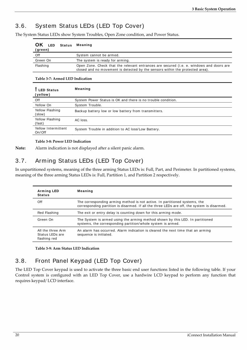
3.6. System Status LEDs (LED Top Cover) The System Status LEDs show System Troubles, Open Zone condition, and Power Status.
OK LED Status (green)
Meaning
Off System cannot be armed.
Green On The system is ready for arming.
Flashing Open Zone. Check that the relevant entrances are secured (i.e. e. windows and doors are closed and no movement is detected by the sensors within the protected area).
Table 3-7: Armed LED Indication
! LED Status (yellow)
Meaning
Off System Power Status is OK and there is no trouble condition.
Yellow On System Trouble.
Yellow Flashing (slow)
Backup battery low or low battery from transmitters.
Yellow Flashing (fast)
AC loss.
Yellow Intermittent On/Off
System Trouble in addition to AC loss/Low Battery.
Table 3-8: Power LED Indication
Note: Alarm indication is not displayed after a silent panic alarm.
3.7. Arming Status LEDs (LED Top Cover) In unpartitioned systems, meaning of the three arming Status LEDs is: Full, Part, and Perimeter. In partitioned systems, meaning of the three arming Status LEDs is: Full, Partition 1, and Partition 2 respectively.
Arming LED Status
Meaning
Off The corresponding arming method is not active. In partitioned systems, the corresponding partition is disarmed. If all the three LEDs are off, the system is disarmed.
Red Flashing The exit or entry delay is counting down for this arming mode.
Green On The System is armed using the arming method shown by this LED. In partitioned systems, the corresponding partition/whole system is armed.
All the three Arm Status LEDs are flashing red
An alarm has occurred. Alarm indication is cleared the next time that an arming sequence is initiated.
Table 3-9: Arm Status LED Indication
3.8. Front Panel Keypad (LED Top Cover) The LED Top Cover keypad is used to activate the three basic end user functions listed in the following table. If your Control system is configured with an LED Top Cover, use a hardwire LCD keypad to perform any function that requires keypad/ LCD interface.

3 Basic System Operation
iConnect Installation Manual
21
Key Function
Service call, see p.39, 5.2.1 Service Call.
Audio message playback/recording. See p. 33, 4.8.2 Message Center.
+ SOS Panic Alarm. See p. 27, 3.12.7, Alarm Activation.
Table 3-10: Front Panel Keypad Functions
3.9. Audible Notification The following table is a summary of tones that audibly notify system status.
Status Tones Description
Positive Acknowledge
1 long tone. The preceding action was accepted.
Negative Acknowledge
5 low tones. The preceding action was not accepted (e.g. an incorrect user code entry).
Exit Delay/ Entry Delay
External Siren: 4 tones.
Internal Siren: 4 tones or Continuous tones.
Continuous tones quicken when there are 15 seconds remaining and quicken again when there are 5 seconds remaining.
The exit/entry delay is counting down.
The number of tones sounded during each delay is determined in programming – see p. 53 8.5 Arming Tones.
Chime 2-tone modulated sequence (similar to a doorbell).
A zone with the Chime option enabled has been opened – see p. 46 7.3.5 Chime .
Arm 3-tone modulated sequence (low to high) sounded twice
The system has been armed using any of the arming methods.
Disarm 3-tone modulated sequence (high to low).
The system has been disarmed.
Home Automation Rapid 2-tone modulated sequence.
An HA unit has been turned On or Off using a wireless keypad or keyfob – see p. 54 8.6 Home Automation Tones .
System Trouble 4 rapid tones sounded once per minute.
A trouble condition has been detected, press for further details. For Fire Trouble Tones, there is a programmable option to repeat fire-related trouble tones until the problem has been taken care of – see p. 55, 8.7.3 Fire Trouble Tones.
Table 3-11: Audible Notification
3.9.1. System Trouble Tones
In the event of system trouble, the iConnect Control System sounds a series of tones to alert the user. To silence these tones, press and scroll through the system trouble list displayed on the LCD. When the trouble condition is restored, it is removed from the system trouble list. Note: For this feature to function, Trouble Tones must be enabled in programming – see p. 54, 8.7.1 System
Trouble Tones. System trouble tones are not sounded from 10:00pm to 7:00am so as not to disturb household members who may be asleep. However, you can program the system to immediately annunciate telephone trouble at all times – see p. 55, 8.7.2 Telephone Trouble Tones.

3 Basic System Operation
iConnect Installation Manual 22
3.9.2. Vocal Message Annunciation
Certain versions of the iConnect Control System hardware support vocal annunciation of system status. If this feature is enabled in programming (see p. 61, 9.13 Vocal Messages), the system plays short messages to indicate arming, disarming, bypassed zones, system trouble, message waiting, and water alarm. Note: The availability of the Vocal Message annunciation feature is hardware dependent
3.9.3. Alarm Sounding Patterns
The following table summarizes the system’s various alarm patterns. Alarm Alarm Pattern Description Sounds
Burglary ON (continuously) Siren
Fire ON - ON - ON, 1.5-second pause, ON - ON – ON... Siren
Gas ON - ON - ON - ON (short bursts), 5 second pause, ON - ON - ON - ON... Siren
Medical ON (continuously) – only applicable for MedicalEmergency alarm from zone Siren
Flood/Environmental 4 rapid tones sounded once per minute (same as Trouble tones) Buzzer
Table 3-12: Alarm Patterns
3.10. Arming and Disarming – Unpartitioned Systems The following section explains how to arm and disarm the Control System using the front panel keypad, hardwire LCD keypad, and EL-2724 Wireless Terminal. iConnect Control System allows partitioning of your home. For Partitioned system arming and disarming, see p. 24, 3.11 Arming/Disarming – Partitioned Systems.
3.10.1. Arming
If partitioning is disabled, you have three arming modes available: full, part, and perimeter. Figure 3-5 illustrates the three arming modes. In each diagram, the protected area is shaded.
Full Armed Part Armed Perimeter Armed Figure 3-5: Arming Modes
The arming options are entirely flexible. You can program each sensor to be included in any combination of the three arming modes – see p. 45, 7.3.2 Arm Set. Additionally, each arming mode has a separate exit and entry delay. Below you can see another, more complicated example of how can the premises be divided. In this example, the garage is included in full + part + perimeter arming, the house perimeter zones are included in full + perimeter arming, and the house interior zones, in full arming only. So, part arming allows the user to arm the garage, perimeter arming is used to secure the house perimeter at nights, and the full arming is used when leaving the house. Figure 3-6 illustrates this example. In each diagram, the protected area is shaded.
Full armed Part armed Perimeter armed Figure 3-6: Partition Arming Modes: Garage Example.

3 Basic System Operation
iConnect Installation Manual
23
3.10.2. Arming Keys
The Arming keys enable you to arm the system using any of the three arming methods: -- Full, Part and Perimeter.
Full / Part / Perimeter Figure 3-7: Arming Keys
3.10.3. Full Arming
Full arming is designed for when the occupant vacates the premises. To fully arm the system using the front panel keypad, LCD keypad, or EL-2724 Wireless Terminal: 1. Check if the system is ready to arm. 2. Press the Full arming key on the keypad. 3. If One-Key Arming is disabled, enter your user code.
3.10.4. Part Arming
Part arming is designed for when the occupant intends to remain inside one part of the premises and secure another part. To partially arm the system using the front panel keypad or EL-2724 Wireless Terminal: 1. Check if the system is ready to arm. 2. Press the Part arming key on the keypad. 3. If One-Key Arming is disabled, enter your user code. To partially arm the system using the hardwire LCD keypad: 1. Check if the system is ready to arm. 2. Press PART on the keypad. 3. Select Part arming. 4. If One-Key Arming is disabled, enter your user code.
3.10.5. Perimeter Arming
Perimeter arming is designed for when the occupant intends to remain inside the premises and secure the perimeter. To arm the system’s perimeter using the front panel keypad or EL-2724 Wireless Terminal: 1. Check if the system is ready to arm. 2. Press the Perimeter arming key on the keypad. 3. If One-Key Arming is disabled, enter your user code. To arm the system’s perimeter using the hardwire LCD keypad: 1. Check if the system is ready to arm. 2. Press PART on the keypad 3. Select Perimeter arming. 4. If One-Key Arming is disabled, enter your user code.
3.10.6. Combination Arming
The system allows you to activate a combination of two arming methods. If you Perimeter arm the system, you may also activate Full or Part arming. Likewise, you can Perimeter arm the system after activating Full or Part arming. It is not important which arming mode you choose first. Note: You can activate the second arming mode only during the exit delay of the first arming mode. When
the first exit delay expires, you cannot activate a second arming mode.

3 Basic System Operation
iConnect Installation Manual 24
For combination arming, perform the following procedure: 1. Check if the system is ready to arm. 2. Activate the first arming mode. 3. If One-Key Arming is disabled, enter your user code. 4. While the exit delay of the first arming mode is counting down, activate the second arming mode. 5. If One-Key Arming is disabled, enter your user code. Note: It is not possible to activate Full and Part arming modes simultaneously. It is necessary to disarm first
when changing from one arming mode to another arming mode. The exit delays of the two arming modes are entirely independent. The moment an arming mode is activated, its exit delay begins to count down. The entry delay depends on which sensor was tripped first. For example, if the sensor is included in Full arming, the entry delay for Full arming counts down – see p. 45, 7.3.2 Arm Set. If the sensor is included in both activated arming modes, the entry delay for Perimeter arming counts down. Note: If, due to open zones, the system is not ready to activate the second arming mode then both arming
methods are canceled. In this case, check that the relevant entrances are secured and start the entire arming sequence again.
Disarming cancels both active arming modes.
3.10.7. Disarming
When an entry/exit sensor is tripped, the entry delay counts down; each arming method has its own entry delay. To disarm the system:
Enter a valid user code, the system is disarmed. Note: In unpartitioned systems, you can only disarm all the active arming modes.
3.11. Arming/Disarming – Partitioned Systems
3.11.1. Arming
If the system partitioning is enabled, you have, in addition to full arming, two partitions that you can customize according to the client's needs. The arming options are entirely flexible. You can program each sensor to be included in any combination of the three arming modes – see p. 45, 7.3.2 Arm Set. Additionally, each arming mode has a separate exit and entry delay. Each partition can be armed and disarmed individually and independently of full arming (there may be zones assigned to full arm only). But when you full arm the system, the two partitions are also automatically armed. For information on partitioning option programming, see p. 64, 9.22 Partition . For information on assigning peripherals to specific partitions: see:
Zones – p. 45, 7.3.2 Arm Set; Keyfobs – p. 49, 7.4.3 Partition Set. Smartkeys – p. 52, 7.8.2 Partition Set.
Common zones
Our example illustrates a special advantage partitioned systems have, namely the common zones. A common zone is a zone that belongs to both partitions. An alarm is generated from common zones only if the system has been Fully Armed or both partitions 1 and 2 have been armed. In the following example one part of the house is assigned to Partition 1, another part to partition 2. The common zone is in the corridor that belongs to both partitions. In each diagram, the protected area is shaded. Notes: If the only zones open are common zones, the system is still ready to arm. The common zones are relevant only for the Normal, Entry/Exit and Follower zone types. For this
reason, when defining a zone as a Common zone (arm set = 123 or 23) choose zone type Normal, Entry/Exit, or Follower.
In our example a common zone is placed in the corridor that belongs to both partitions. Only when both users leave and arm their partitions, the common zone is activated and the corridor is protected. When any of the users returns and

3 Basic System Operation
iConnect Installation Manual
25
disarms his partition, the corridor is also disarmed in order to give the user access to his room. This is because the common zone is active only when both partitions are armed.
Partition 1 armed Partition 2 armed Both partitions armed Figure 3-8: Partition Arming Modes: Corridor Example.
Each arming mode has a separate exit and entry delay. Note: The entry delay timeout started by an Entry/Exit common zone is such as defined for Full Arming.
3.11.2. Arming Keys
The Arming keys enable you to arm the system using any of the three arming methods: Full, Partition 1, and Partition 2.
Full / Partition 1 / Partition 2 Figure 3-9: Arming Keys
3.11.3. Partition Arming
To arm a partition using the LCD Front Panel keypad: 1. Check if the system is ready to arm. 2. Press the Partition 1 arming key on the keypad to arm Partition 1.
- or - Press the Partition 2 arming key on the keypad to arm Partition 2.
3. If One-Key Arming is disabled, enter your user code. To arm a partition using the hardwire LCD keypad: 1. Check if the system is ready to arm. 2. Press the Part arming key on the keypad. 3. If One-Key Arming is disabled, enter your user code. 4. Use the menu navigation buttons ( / ) to choose the required arming method. 5. Press ; the exit delay begins to count down. At the end of the exit delay, the system/partition is
armed.
3.11.4. Combination Arming
The system allows you to activate a combination of two arming modes. When one user leaves, he arms his partition (1 or 2). When the second user leaves, he arms the second partition; the commons zones are activated. Note: If the only zones open are common zones, the system is still ready to arm.
3.11.5. Disarming
When an entry/exit sensor is tripped, the entry delay counts down; each partition has its own entry delay. To disarm the system:
Enter a valid user code. If both partitions are armed, and your user code is assigned to both partitions, the system
prompts Select Partition. In this case, press one of the arming keys on the front panel keypad

3 Basic System Operation
iConnect Installation Manual 26
(Full for the whole system, Part for partition 1, or Perimeter for partition 2) within 6 seconds. The system/partition is disarmed.
If the user code is assigned to one partition only, or only one partition is armed, this partition is disarmed immediately.
3.12. Additional Arming Options
3.12.1. Forced Arming
Forced arming enables you to arm the system when the system is not ready. For example, if a door protected by a magnetic contact is open, you may arm the system on condition that the door will be closed by the end of the Exit delay. If the door is still open after the exit delay expires, an alarm is generated. Two conditions enable you to perform Forced arming:
Forced arming is enabled – see p. 56, 9.3.1 Forced Arm. The sensor that is causing the System Not Ready condition is Force Arm enabled – see p. 47, 7.3.6 Force
Arm.
3.12.2. Instant Arming
Instant arming is a feature that allows you to cancel the entry delay after Part or Perimeter, or Partition arming the system. For this feature to function, it must be enabled in programming – see p. 57, 9.3.4 Instant Arming. To instantly arm the system. 1. Check if the system is ready to arm. 2. Press the Part or Perimeter arming key on the keypad and enter your user code if One-Key Arming is disabled. 3. Press and hold down on your keypad until the message Instant Arming, OK? is displayed 4. Press ; the entry delay for the current arming period is canceled.
3.12.3. Remote Arming/Disarming via SMS
You can arm and disarm the system remotely by sending the SMS commands from a cellular phone to the Cellular Communication Module (GPRS or Ethernet). Additionally, you can check the arm status of the system by sending an Arm Status request message. Each SMS command contains the following elements:
SMS Command Descriptor (up to 43 characters of free text) # (delimiter – separates the descriptor from the actual command) User Code (4 digits) Command (120=Disarm all Partitions, 121=Full Arm, 122=Part Arm/Partition 1 Arm, 123=Perimeter
Arm/Partition 2 Arm, 124=Full + Perimeter Arm, 125=Part + Perimeter Arm/Partitions 1 and 2 Arm, 128=Partition 1 Disarm, 129=Partition 2 Disarm, 200=Arm Status)
The following example shows the format of an SMS command for arming the system:
F U L L A R M # 1 2 3 4 1 2 1
Caution: While the SMS Command Descriptor is optional, you must start the SMS command with the #
symbol for the system to accept the command. After an SMS command is executed by the system, you can program the system to return a confirmation message to the sender – see p. 73, 10.7.5 SMS Confirmation.
3.12.4. Arm Status Reply
On receiving an Arm Status request message, the system returns a status message to the sender. This message includes the system status and the descriptor of the user or the device used to arm/disarm the system. The following example shows an Arm Status Reply message reporting that the system was fully armed by Master User.
F U L L A R M E D - M A S T E R U S E R

3 Basic System Operation
iConnect Installation Manual
27
3.12.5. Remote Arming/Disarming via DTMF
Using the Telecontrol feature, you can arm and disarm the system via the telephone with DTMF commands. For further information on the Telecontrol features, see p. 38, 5.1.5 Arm/Disarm DTMF Commands.
3.12.6. Remote Arming/Disarming via WUAPP
You can arm and disarm the system remotely using the WUAPP (Web User Application) – see p. 121, Arm/Disarm.
3.12.7. Alarm Activation
In the event of an emergency, the user can generate three kinds of alarms from the front panel keypad, hardwire LCD keypads, keyfobs, and the EL-2724 Wireless Terminal. To activate an SOS Panic alarm from the front panel keypad and Wireless Terminal:
Press and hold down the Home Automation On and Off buttons simultaneously.
Figure 3-10: SOS Alarm Activation (Front Panel Keypad/Wireless Terminal)
To activate an SOS Panic alarm from the LCD keypad:
Press and hold down the and buttons simultaneously.
Figure 3-11: SOS Alarm Activation (Hardwire LCD Keypad)
To activate a SOS Panic alarm from the LED Top cover:
Press the Service Call and Message Play buttons simultaneously.
Figure 3-12: SOS Panic Alarm Activation (LED Top Cover)
To activate a SOS Panic alarm from the Keyfob EL-2714:
Press B1 and B2 buttons simultaneously.
Figure 3-13: SOS Panic Alarm Activation (EL-2714)
To activate a Fire alarm from the front panel keypad or hardwire LCD keypad:
Press and hold down buttons 1 and 3 simultaneously.
Figure 3-14: Fire Alarm Activation
To activate a Medical alarm from the front panel keypad or hardwire LCD keypad:
Press and hold down buttons 4 and 6 simultaneously.
Figure 3-15: Medical Alarm Activation

4 Advanced System Operation
iConnect Installation Manual 28
4. Advanced System Operation Besides the basic arming functions described in the previous chapter, you can access additional functions via the menu. This chapter describes these functions and the menu navigation procedure.
4.1. Menu Navigation
Figure 4-1: On-board Keypad Layout
The Front Panel/LCD keypads' friendly, menu-driven interface is designed to facilitate operation and provide a gentler learning curve for first-time users. You can navigate through the menus using the arrow navigation keys ( / ) and make simple yes/no decisions using the and keys. For example, perform the following procedure to navigate to Service, Interface Test. 1. Press to enter Menu mode. 2. Enter an authorized user code; the first menu item, 1. Cancel Report, is displayed. 3. Press until 7. Service is displayed. 4. Press to enter the Service menu. 5. Press until 5. Interface Test is displayed. 6. Press to choose the displayed function. Note: Press the key to return to the previous menu level. Press this key when you are in the main menu to
exit Menu mode. As an alternative to scrolling through menu options, you may enter a function’s shortcut once you have entered Menu mode. Shortcut numbers appear in square brackets in the procedures throughout this manual.
4.1.1. Menu Mode Timeout
Menu mode automatically terminates a certain amount of time after the last keystroke. The duration of this timeout depends upon which code is used to enter the menu. Usually the Menu Mode Timeout is two minutes but if you enter menu mode using the Installer code, the timeout is extended to fifteen minutes.
4.2. Cancel Report This feature allows the user to cancel false alarms. Cancel Report behavior depends on time when it is performed. If the user selects Cancel Report:
…before the alarm/restore message is sent, all the pending alarm or restore messages in the queue are aborted and marked "Cancelled" in the event log.
…within 5 minutes since an alarm, a Cancel Report event and the user number are sent to the Central Station;
…at the moment when the event is being reported (communication in progress), the event reporting is not cancelled;
Note: Non-alarm events (system trouble, arm/disarm etc.) are not aborted by Cancel Report.
Menu Navigation Keys
HA Off
Service Call Key
HA On
Alphanumeric Keypad

4 Advanced System Operation
iConnect Installation Manual
29
To activate cancel report: From the main menu, select Cancel Report. [1].
4.3. Zone Bypassing/Unbypassing When a sensor is bypassed, it is ignored by the system and does not generate an alarm when triggered. To bypass or unbypass a sensor: 1. From the Bypass Zones menu, select Bypass/Unbyp. [21]. 2. Using the arrow keys, scroll to the sensor you want to bypass or unbypass. 3. Press to change the bypass status. 4. Press ; Save Changes? is displayed. 5. Press to confirm the changed bypass status. To unbypass all sensors (In partitioned systems, Master Code is required): 1. From the Bypass Zones menu, select Unbypass All [22]. 2. Press ; all sensors are unbypassed. Note: All bypassed zones are automatically unbypassed when the system is disarmed.
A Fire zone cannot be bypassed. In partitioned systems, to bypass/unbypass a zone, you must have a user code assigned to the same
partition as the zone is.
4.4. User Codes The Control System supports up to 32 individual user codes. Each of these codes is four digits long. Most system operations require you to enter a valid user code. The ability to perform an operation is defined by your user code’s authorization level. These authorization levels are pre-defined for each code as explained below. Notes: Codes 1-29 can be edited only by the Master code. The Installer code, Guard Code and the Central Station TWA Code can be edited only by the installer.
Code 1: Master Code
The Master code is the highest user authorization level. With the Master code, you can edit all other user codes except the Installer code, the Guard code and the Central Station TWA Code. Additionally, the Master code grants access to the Event Log, the Service menu and Home Automation Schedule programming. The Master code is a "controlled" code. Arming and disarming using this code causes the Control System to notify the central station with an Arm/Disarm event message*. In partitioned systems, Master Code is always assigned to both partitions. Caution: The default Master code is 1234. Change this code immediately after installing the system!
Codes 2-19: Controlled Codes*
When you use a controlled user code for arming and disarming, the Control System notifies the central station with an Arm/Disarm event message.
Codes 20-25: Non-controlled Codes
Non-controlled codes do not cause the Control System to send Arm/Disarm event messages to the central station. The Control System sends a Disarm message only if you use this code to disarm the system after an alarm occurrence.
Codes 26-27: Limited Codes
A Limited code enables the user to issue a code that is valid for one day only. This code automatically expires 24 hours after it has been programmed. These codes are "controlled" in that their use for Arm/Disarm is notified to the central station.
* Only if arm/disarm reporting is enabled during System Programming
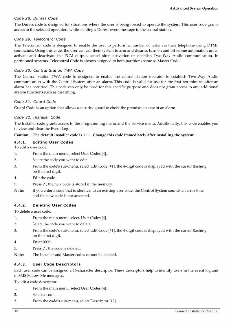
4 Advanced System Operation
iConnect Installation Manual 30
Code 28: Duress Code
The Duress code is designed for situations where the user is being forced to operate the system. This user code grants access to the selected operation, while sending a Duress event message to the central station.
Code 29: Telecontrol Code
The Telecontrol code is designed to enable the user to perform a number of tasks via their telephone using DTMF commands. Using this code, the user can call their system to arm and disarm, turn on and off Home automation units, activate and deactivate the PGM output, cancel siren activation or establish Two-Way Audio communication. In partitioned systems, Telecontrol Code is always assigned to both partitions same as Master Code.
Code 30: Central Station TWA Code
The Central Station TWA code is designed to enable the central station operator to establish Two-Way Audio communication with the Control System after an alarm. This code is valid for use for the first ten minutes after an alarm has occurred. This code can only be used for this specific purpose and does not grant access to any additional system functions such as disarming.
Code 31: Guard Code
Guard Code is an option that allows a security guard to check the premises in case of an alarm.
Code 32: Installer Code
The Installer code grants access to the Programming menu and the Service menu. Additionally, this code enables you to view and clear the Event Log. Caution: The default Installer code is 1111. Change this code immediately after installing the system!
4.4.1. Editing User Codes To edit a user code: 1. From the main menu, select User Codes [4]. 2. Select the code you want to edit. 3. From the code’s sub-menu, select Edit Code [#1]; the 4-digit code is displayed with the cursor flashing
on the first digit. 4. Edit the code. 5. Press ; the new code is stored in the memory. Note: If you enter a code that is identical to an existing user code, the Control System sounds an error tone
and the new code is not accepted.
4.4.2. Deleting User Codes
To delete a user code: 1. From the main menu select, User Codes [4]. 2. Select the code you want to delete. 3. From the code’s sub-menu, select Edit Code [#1]; the 4-digit code is displayed with the cursor flashing
on the first digit. 4. Enter 0000. 5. Press ; the code is deleted. Note: The Installer and Master codes cannot be deleted.
4.4.3. User Code Descriptors
Each user code can be assigned a 16-character descriptor. These descriptors help to identify users in the event log and in SMS Follow-Me messages. To edit a code descriptor: 1. From the main menu, select User Codes [4]. 2. Select a code. 3. From the code’s sub-menu, select Descriptor [#2].
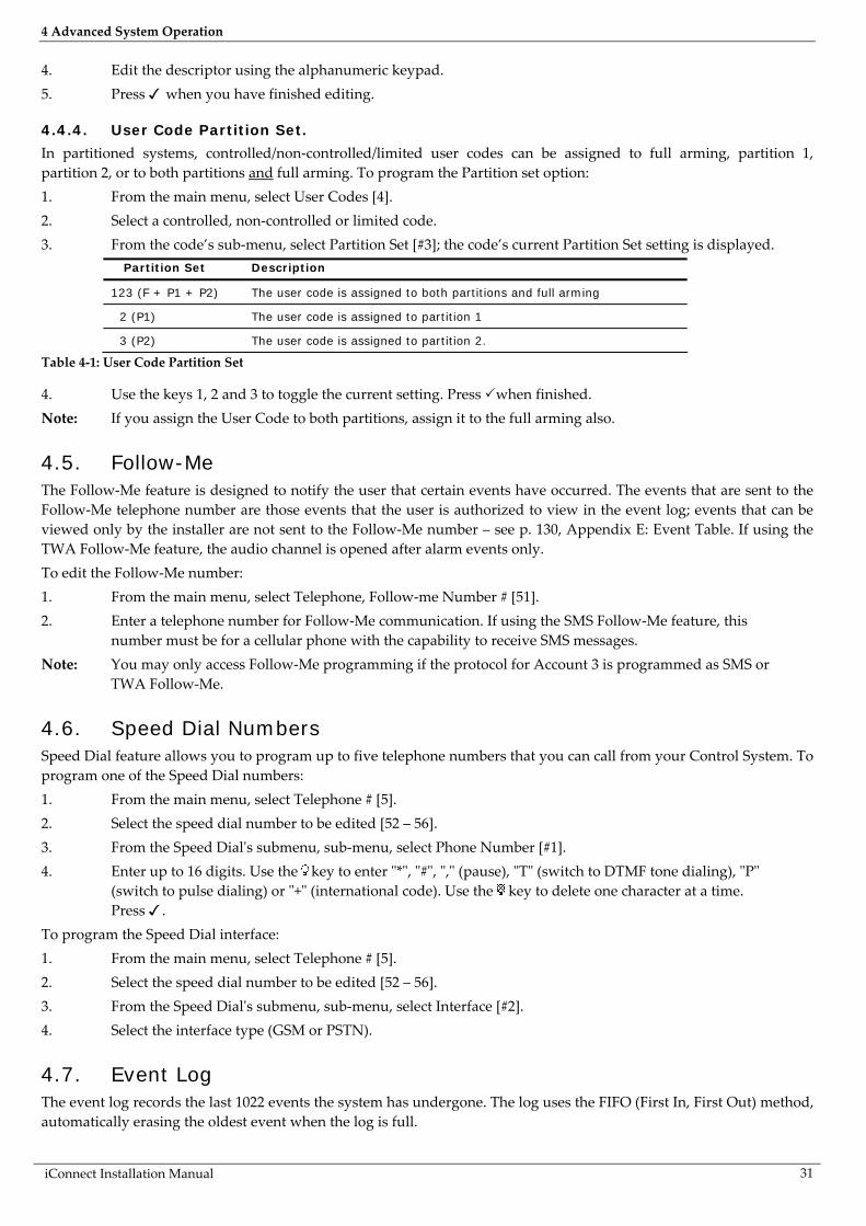
4 Advanced System Operation
iConnect Installation Manual
31
4. Edit the descriptor using the alphanumeric keypad. 5. Press when you have finished editing.
4.4.4. User Code Partition Set.
In partitioned systems, controlled/non-controlled/limited user codes can be assigned to full arming, partition 1, partition 2, or to both partitions and full arming. To program the Partition set option: 1. From the main menu, select User Codes [4]. 2. Select a controlled, non-controlled or limited code. 3. From the code’s sub-menu, select Partition Set [#3]; the code’s current Partition Set setting is displayed.
Partition Set Description
123 (F + P1 + P2) The user code is assigned to both partitions and full arming
2 (P1) The user code is assigned to partition 1
3 (P2) The user code is assigned to partition 2.
Table 4-1: User Code Partition Set
4. Use the keys 1, 2 and 3 to toggle the current setting. Press when finished. Note: If you assign the User Code to both partitions, assign it to the full arming also.
4.5. Follow-Me The Follow-Me feature is designed to notify the user that certain events have occurred. The events that are sent to the Follow-Me telephone number are those events that the user is authorized to view in the event log; events that can be viewed only by the installer are not sent to the Follow-Me number – see p. 130, Appendix E: Event Table. If using the TWA Follow-Me feature, the audio channel is opened after alarm events only. To edit the Follow-Me number: 1. From the main menu, select Telephone, Follow-me Number # [51]. 2. Enter a telephone number for Follow-Me communication. If using the SMS Follow-Me feature, this
number must be for a cellular phone with the capability to receive SMS messages. Note: You may only access Follow-Me programming if the protocol for Account 3 is programmed as SMS or
TWA Follow-Me.
4.6. Speed Dial Numbers Speed Dial feature allows you to program up to five telephone numbers that you can call from your Control System. To program one of the Speed Dial numbers: 1. From the main menu, select Telephone # [5]. 2. Select the speed dial number to be edited [52 – 56]. 3. From the Speed Dial's submenu, sub-menu, select Phone Number [#1]. 4. Enter up to 16 digits. Use the key to enter "*", "#", "," (pause), "T" (switch to DTMF tone dialing), "P"
(switch to pulse dialing) or "+" (international code). Use the key to delete one character at a time. Press .
To program the Speed Dial interface: 1. From the main menu, select Telephone # [5]. 2. Select the speed dial number to be edited [52 – 56]. 3. From the Speed Dial's submenu, sub-menu, select Interface [#2]. 4. Select the interface type (GSM or PSTN).
4.7. Event Log The event log records the last 1022 events the system has undergone. The log uses the FIFO (First In, First Out) method, automatically erasing the oldest event when the log is full.

4 Advanced System Operation
iConnect Installation Manual 32
To view the event log: 1. From the Event Log menu, select View Log [61]; a summarized version of the most recent event is
displayed. Press the key to view the time/date stamp or the device/user number on the second row of the display.
2. Use the arrow keys to scroll through the events. 3. When you have finished viewing, press to exit the log. The event log displays the following information for each event:
The event descriptor – a brief description of the event that occurred. The zone where the event occurred. Time/date stamp – the exact time the event occurred. Report details – a single character indicating whether the event was reported to the central station. The
options available are R: Report Sent, F: Report Failed, C: Report Canceled or N: No Report. Figure 4-2 shows the detailed event log entry for a Fire alarm on November 14th 2008. The event was successfully reported to the central station.
Figure 4-2: Detailed Event Log Display
4.7.1. Event Log Authorization Levels
Every event that occurs is recorded in the event log. However, certain events are intended for the installer only. Those events include various service messages that are of little interest to the regular user. The View Log function requires you to enter either the Master or Installer code. The events that are displayed depend on which code you use to enter the log – see p.130, Appendix E: Event Table.
4.7.2. Clearing the Event Log
The Clear Log function erases all events from the log. After performing this function, a Clear Log event is recorded in the log. The Clear Log function is accessible using the Installer code only. To clear the event log: 1. From the Event Log menu, select Clear Log [62]; the OK? confirmation message is displayed. 2. Press ; the log is cleared -- See p.130, Appendix E: Event Table. Note: For certain versions of the iConnect Control System software, the Clear Log function may be disabled.
4.8. Service Menu The Service menu is accessible using either the Installer or Master code. This menu includes various functions that enable you to test the system effectively.
4.8.1. Set Time & Date
The time and date are used to time stamp events in the event log. Additionally the time is also displayed on the LCD display. To set the time: 1. From the Service menu, select Set Time/Date, Set Time [7011]. 2. Enter the current time. 3. Press ; the time is modified.

4 Advanced System Operation
iConnect Installation Manual
33
To set the date: 1. From the Service menu, select Set Time/Date, Set Date [7012]. 2. Enter the current date. 3. Press ; the date is modified. Note: The format of the time and date is defined in the System Options – see p.58, 9.6.3 Time/Date Format. If
you are setting the time in 12hr format, use the key to toggle between AM and PM.
4.8.2. Message Center
The iConnect Control System Message Center is designed to allow the user to record a short message that may be played back later by another user. After a message is recorded, Message Waiting is displayed on the LCD until the message is played back. If the Vocal Message option is enabled, the Message Waiting vocal message is sounded. Note: Recording a new message automatically overwrites all the previous messages in the Message Center. To play back a recorded message:
From the Service menu, select Messages, Play Message [7021]. To record a message: 1. From the Service menu, select Messages, Record Message [7072]. 2. Press to start recording the message. 3. Record your message. The message may be up to twenty seconds long.
Time left out of the 20 seconds' timeout is displayed on the LCD. 4. Press to stop recording; the message is automatically played back and OK? Is displayed. 5. Press to save your recording. The Record and Play options can also be accessed via a convenient shortcut without needing to enter a valid user code. To play back a recorded message via a keypad shortcut or using the EL-2724 Wireless Terminal:
From Standby mode, press then . To record a message via a keypad shortcut or using the EL-2724 Wireless Terminal:
From Standby mode, press then . On the EL-2724 Wireless Terminal, both LEDs flash in tandem during recording.
The LED Top Cover keypad has two buttons for Message Play back and Recording – see p. 19, 3.5 Front Panel Layout (LED Top Cover). When there is a new message waiting, the Message Play button is flashing fast. To play back a recorded message using LED Top Cover keypad:
Press the Message Play button . During the play back, the Play button is lit.
To record a message using LED Top Cover keypad:
1. Press the Message Record button . 2. Record your message, the Message Record button is lit during recording. 3. Press the Record button again to stop recording. The message is then recorded, played back, and
saved. Note: when you have 5 seconds left, the Record and Service Call buttons start flashing. To delete a message: 1. From the Service menu, select Messages, Delete Message [7023]; OK? Is displayed. 2. Press , the message is deleted. To delete a message using LED Top Cover keypad:
Press and hold down the Message Record button for 3 seconds. The Record button backlight flashes quickly. The Control System sounds a tone.

4 Advanced System Operation
iConnect Installation Manual 34
4.8.3. Wireless Siren Test
To test the wireless siren: From the Service menu, select WL Siren Test [703]; the external siren is sounded briefly.
4.8.4. Siren Test
To test the Control System’s built-in siren: From the Service menu, select Siren Test [704]; the Control System’s built-in siren is sounded briefly.
4.8.5. Interface Test
The Interface test enables you to check if the speaker, LEDs and LCD are functioning correctly. To test the system interface:
From the Service menu, select Interface Test [705]; a short sequence of chimes are sounded from the speaker, all LEDs flash and the LCD is tested on all connected LCD keypads.
4.8.6. Walk Test To initiate Walk Test mode: 1. From the Service menu, select Walk Test [706]; a list of registered sensors appears. 2. Trigger each sensor; when the system receives a successful transmission from a sensor, the sensor is
removed from the list. 3. When all the sensors are removed from the list, End Walk Test is displayed. 4. Press to exit Walk Test mode.
4.8.7. Transmitters
The Transmitters menu offers two utilities that serve as a valuable aid during installation. The first utility, TX List, is a scrollable inventory of all registered transmitters and their last reported status. To view the TX list: 1. From the Service menu, select Transmitters, TX List [7071]; the first transmitter on the list is displayed. 2. Using the arrow buttons, scroll through the transmitter list. 3. When you have finished viewing, press to exit the list. The TX list displays the following information for each transmitter:
The zone/device number or descriptor. Press the key to toggle the display. The signal strength of the last received transmission. An abbreviation indicating the last received status of the transmitter – see Table 4-2.
Item… Description…
OK The transmitter is functioning correctly
TA Tamper condition
BT Battery low
OS The transmitter is out of synchronization
NA The transmitter is inactive – see p. 44, 7.2.3 Supervision Time
Table 4-2: Transmitter Status Abbreviations
Figure 4-3: TX List Display

4 Advanced System Operation
iConnect Installation Manual
35
Note: In most cases, an "out of synchronization" condition indicates that an unauthorized attempt at grabbing the transmission has occurred – i.e. a previous transmission has been recorded and sent by somebody trying to violate the system.
The second utility, TX Test, enables you to identify transmitters and test their signal strength. In TX Test mode, each time a transmission is received, the activated transmitter is displayed. If you enter this function using the Master code, a chime is sounded every time a transmission is received. If you enter this function using the Installer code, a sequence of tones are sounded indicating the transmitter’s signal strength – see Table 4-3. This feature helps you to determine the best location to install a transmitter. Note: The lowest recommended signal strength for any installed transmitter is 5. If the received signal
strength is lower than 5, relocate the transmitter. Signal Strength
Tones
0-2 1 Tone
3-5 2 Tones
6-8 3 Tones
8-9 4 Tones
Table 4-3: Signal Strength Tones
To initiate TX Test mode: 1. From the Service menu, select Transmitters, TX Test [7072]. 2. Activate a transmitter; the transmitter’s details are displayed. 3. When you have finished, press to exit TX Test mode.
4.8.8. Audio Volume
To adjust the sensitivity of the microphone and the volume of the speaker: 1. Establish a two-way audio connection – see 5.1.4 Telecontrol Call Procedure. 2. From the Service menu, select Audio Volume [708]. 3. Using the arrow keys on the Front Panel keypad, adjust the setting according to the following table.
Key… Function
1 Increases microphone sensitivity
4 Reduces microphone sensitivity
3 Increases speaker volume
6 Reduces speaker volume
Table 4-4: Voice Level Adjustment
4. Press ; the new settings are stored in the memory.
4.8.9. GSM Signal Strength
You can measure the GSM signal strength. This function and the RF RSSI level (see below) enable you to calculate the optimal location to install the Control System with the Cellular Communication Module. To view the GSM signal strength reading:
From the Service menu, select RF & GSM Level, GSM Signal [7091]; the signal strength of the cellular network is displayed.
Note: In severe cases of low GSM signal consider using external GSM antenna.
4.8.10. RF RSSI level
You can measure the RF RSSI level (RF noise measured by the systems' receiver) using the system’s RSSI (Received Signal Strength Indication) meter. The Control System will start measuring the RSSI level of the receiver every second, and it will display the result in levels from 1 to 9 – similar to the level of detector transmitter's signal strength. It is recommended that the gap between the RF noise level and the TX signal strength be at least 2. For example, if the RF

4 Advanced System Operation
iConnect Installation Manual 36
RSSI level is 5 and the TX signal strength is 6, consider relocation of the Control System or its peripherals – see p. 9 2.1.1 Wireless Installation Guidelines. The menu will have timeout of 5 minutes. If the installer doesn't exit the menu within 5 minutes of its entry, the Control System will exit all menus. To view the RF RSSI level reading:
From the Service menu, select RF & GSM level, RF RSSI Level [7092]; the RF RSSI level of the Control System's receiver is displayed.
4.8.11. Display Version
To display the system’s software and hardware versions: From the Service menu, select Version [710]; the hardware (HW) and software (SW) versions are
displayed. 4.8.12. Enable Programming
The Enable Programming command enables a user with Master code authorization to grant access to system programming. This feature is relevant only if the Installer Access and/or the RP Access options are programmed as "User Initiated" – see p. 62, 9.14 Installer Access and p. 69, RP Access Options. To grant access to the installer or Remote Programmer:
From the Service menu, select Enable Prog. [711]; a 30-minute time window is opened during which the Installer Code is valid or RP communication may be established.
4.8.13. Global Chime
The Chime feature causes the Control System’s built-in siren to ring when specific zones are triggered. Using the Global Chime option, you can enable or disable this feature for all zones that are defined as Chime enabled – see p.46, 7.3.5 Chime. To enable or disable Global Chime: 1. From the Service menu, select Global Chime [712]. 2. Select either Enabled or Disabled. Note: Though the Service menu is accessible to the Master and Installer only, Global Chime can also be
accessed via a convenient shortcut without needing to enter a valid user code. To access the Global Chime option from Standby mode, press then .
4.8.14. Remote Firmware Update
The Remote Firmware Update command enables a user with Master code authorization to initiate the update. This feature is relevant only if the Remote Firmware Update mode is programmed as "User Initiated" – see p. 74, 10.8.4 Remote Firmware Update To grant access to Remote Firmware Update:
From the Service menu, select, SW Update [713]; a 24-hours time window is opened during which the Remote Firmware Update may be performed.
4.8.15. IP Display
When using Ethernet connection, you can view the LAN IP address of the Control System. To display the IP Address:
From the Service menu, select IP Display [714]; the LAN IP address of the Control System is displayed.

5 Telecontrol and Two-Way Audio
iConnect Installation Manual
37
5. Telecontrol and Two-Way Audio The iConnect Control System offers a range of Telecontrol features that provide remote access via the telephone. These features include Two-Way Audio, remote arming/disarming and cancel siren activation. This chapter explains these features and their operating procedures. Telecontrol features can be separated into two fundamental groups; incoming and outgoing calls. These groups differ in their associated features.
5.1. Incoming Calls The Control System can receive incoming calls from either the user or central station operator. Users may use this feature as a convenient way of contacting their family, operating their system or to check their home when they are away. Additionally, the monitoring service can contact the user in the event of an emergency or use this feature for listen-in alarm verification. For any of the incoming Telecontrol features to function, Telecontrol must be enabled in the Communication Options section of the Programming menu – see p. 72, 10.6.10 Incoming Calls.
5.1.1. User Code Verification
To prevent unauthorized attempts to connect with the Control System, there are two user codes designed for use with the Telecontrol features. The Telecontrol code enables the user to establish communication with the Control System at any time. Additionally, the Central Station TWA Code is used exclusively for Two-Way Audio alarm verification and is only valid for a ten-minute period following an alarm.
5.1.2. Incoming Calls via PSTN
In the case of PSTN communication, the Control System often shares a line with regular telephone handsets, an answering machine or a fax machine. It is therefore important that the Control System distinguish between calls so that it knows when to pick up the relevant call. For this purpose the iConnect Control System employs a double call method. To connect to the Control System using the double call method: 1. Dial the telephone number of the line connected to the Control System. 2. Wait for two or three rings and hang-up. 3. Wait at least five seconds and dial the number again; on the second ring, the Control System picks up
and sounds two DTMF tones.
5.1.3. Incoming Calls via a Cellular Network
The Cellular Communication module has its own individual telephone number and therefore, the double call method is not needed. In this case, the user or central station operator may call the Control System directly.
5.1.4. Telecontrol Call Procedure The following procedure explains how to make a Telecontrol call. The conditions and procedure differ when using PSTN or Cellular Communication. For further information, see the entire section 5.1 Incoming Calls. To make a Telecontrol call: 1. Call the Control System either using the double call method (PSTN) or directly (Cellular); when the
Control System picks up, two DTMF tones are sounded. 2. Enter the Telecontrol code (Code 29) on your telephone within 15 seconds.
Note: Do not enter your user code until you hear the two DTMF tones. Any digits entered before the tones are sounded are disregarded by the system.
3. A DTMF tone is sounded to indicate that the system is ready to receive commands. The following DTMF commands are available:
Press "2" for Two-Way Audio. If the TWA mode is defined as "Simplex" (see p. 72, 10.6.13, TWA Mode.), the audio channel opens in Listen mode (microphone active/speaker mute). To switch to Speak mode, press "1" on your telephone. To switch back to Listen mode, press "0" on your telephone. Note: During the TWA session, you can adjust the speaker volume using the arrow buttons.

5 Telecontrol and Two-Way Audio
iConnect Installation Manual 38
Press "3" to fully arm the system. Press "4XX" to turn HA unit #XX ON. Press "430" to activate PGM output (Unit 30) Press "5XX" to turn HA unit #XX OFF. Press "530" to deactivate PGM output (Unit 30) Press "6" to disarm the system. Press "9" to cancel the siren.
For partitioned systems, arming and disarming commands are different: Press "31" to fully arm the system. Press "32" to arm partition 1. Press "33" to arm partition 2. Press "61" to disarm the entire system. Press "62" to disarm partition 1. Press "63" to disarm partition 2.
Notes: The Arm/Disarm, Home Automation, PGM on/off, and Siren canceling can also be executed at any time during a Two-Way Audio session. Error beeps (three tones) sound in case of a wrong command. To clear the last command, press " " or "#".
The duration of the call is determined by the TC/VM Timeout -- see p. 72, 10.6.11 Telecontrol/Vocal Message Timeout. Ten seconds before the timeout expires, two short DTMF tones are sounded. To extend the call, press "7" on your telephone. This command restarts the timeout.
4. To disconnect before the end of the timeout, press " " then "#" on your telephone.
5.1.5. Arm/Disarm DTMF Commands
During a Telecontrol call, you can arm and disarm the system remotely using the DTMF commands (see above). When arming the system in this way, the system is armed immediately without an exit delay.
5.1.6. HA and PGM DTMF commands
During a Telecontrol call, you can turn On and Off the Home Automation units using the DTMF commands "4XX" (HA unit #XX On) and "5XX" (HA unit #XX Off). PGM unit is defined as HA Unit 30. You can activate and deactivate PGM using the DTMF commands "430" (PGM On) and "530" (PGM Off).
5.1.7. Siren Cancel ("Bell Cancel")
The siren is muted during Two-Way Audio communication. At the end of the call, the siren is re-activated (if the Siren Cut-Off has not yet expired). During the call, pressing "9" on your telephone cancels the re-activation of the siren.
5.1.8. Central Station Two-Way Audio
Central Station Two-Way Audio is an alarm verification feature that enables the central station operator to establish Two-Way Audio communication with the Control System within ten minutes of an alarm. To make a Central Station TWA call: 1. Call the Control System either using the double call method (PSTN) or directly (Cellular); when the
Control System picks up, two DTMF tones are sounded. 2. Enter the Central Station TWA code (Code 30) on your telephone within 15 seconds. Note: Do not enter your user code until you hear the two DTMF tones. Any digits entered before the tones
are sounded are disregarded by the system. 3. If the TWA mode is defined as "Simplex" (see p. 72, 10.6.13 TWA Mode), the audio channel opens in
Listen mode (microphone active/speaker mute). To switch to Speak mode, press "1" on your telephone. To switch back to Listen mode, press "0" on your telephone.

5 Telecontrol and Two-Way Audio
iConnect Installation Manual
39
4. The duration of the call is determined by the TC/VM Timeout -- see p. 72, 10.6.11 Telecontrol/Vocal Message Timeout. Ten seconds before the timeout expires, two short DTMF tones are sounded. To extend the call, press "7" on your telephone. This command restarts the timeout.
5. To disconnect before the end of the timeout, press " " then "#" on your telephone.
5.2. Outgoing Calls The iConnect Control System can make Two-Way Audio calls to the user or central station in the event of an alarm. This feature is designed for medical, panic alarms, and for alarm verification.
5.2.1. Service Call
The Service Call feature enables the user to establish a two-way audio connection with the central station operator. For further information on how to program this feature, see p. 70, 10.5 Service Call. To initiate a Service Call:
Press the up arrow key press and hold Service Call key for a few seconds.
The Control System starts to dial. To initiate a Service Call using LED Top Cover:
Press and hold the Service Call button for a few seconds.
The Control System starts to dial and the backlight of the Service Call button is lit. If the TWA mode is defined as "Simplex" (see p. 71, 10.6.13 TWA Mode), the audio channel opens in Listen mode (microphone active/speaker mute). The operator may switch to Speak mode, by pressing "1" on their telephone. Pressing "0" switches back to Listen mode. On the LED Top cover, the Service Call button backlight flashes to indicate Listen mode.
5.2.2. TWA Alarm Reporting In the event of Burglary, Fire and Medical alarms, the Control System is able to report the events and then stay on the line after acknowledgment is received (ACK 2). This allows the operator to verify the alarm or provide assistance in the event of an emergency. For this feature to function, you must enable Two-Way Audio for both the account and the event group. The sequence for Two-Way Audio during alarm reporting is as follows: 1. An alarm event is sent to the central station and acknowledgment is received (ACK 2). 2. If Two-Way Audio is enabled for the account and event group, the Control System stays on the line
and opens the audio channel. 3. If the TWA mode is defined as "Simplex" (see p. 72, 10.6.13 TWA Mode), the audio channel opens in
Listen mode (microphone active/speaker mute). The operator may switch to Speak mode, by pressing "1" on their telephone. Pressing "0" switches back to Listen mode.
4. The duration of the call is determined by the TC/VM Timeout. Ten seconds before the timeout expires, two short DTMF tones are sounded. To extend the call, the operator presses "7" on their telephone. This command restarts the timeout.
5. To disconnect before the end of the timeout, the operator presses " " then "#" on their telephone. If multiple events are sent, the Control System sends all the events before opening the audio channel. Note: When using the SIA protocol for event reporting, this feature functions in "listen-in" mode only.
5.2.3. Two-Way Audio after Vocal Messages
If Two-Way Audio is enabled for a Vocal Message account, the user can open the audio channel by pressing "2" on their telephone after the system has played all of the event messages. The sequence for Two-Way Audio after a vocal message is as follows: 1. An event occurs and the Control System calls the telephone number of the first Voice Report Account
chosen. 2. When the user answers the call, the Home ID message and the relevant event message are played.

5 Telecontrol and Two-Way Audio
iConnect Installation Manual 40
3. If Two-Way Audio is enabled for the Voice Report account, the user presses "2" on their telephone to open the audio channel.
4. The duration of the call is determined by the TC/VM Timeout. Ten seconds before the timeout expires, two short DTMF tones are sounded. To extend the call, the user presses "7" on their telephone. This command restarts the timeout.
5. To disconnect before the end of the timeout, the user presses " " then "#" on their telephone.
5.2.4. TWA Follow-Me The TWA Follow-Me feature is designed to establish a Two-Way Audio connection with the user in the event of an alarm. For this feature to function, the account’s protocol must be defined as TWA Follow-Me. The sequence for a Two-Way Audio Follow-Me call is as follows: 1. An alarm occurs. 2. The Control System dials the programmed telephone number and sounds two DTMF tones when you pick up
the call. 3. Press "2" on your telephone; the Control System opens the audio channel. Note: If you press "9" to answer the call, the Control System simultaneously cancels the siren when opening
the audio channel. 4. If the TWA mode is defined as "Simplex", (see p. 71, 10.6.13 TWA Mode), the audio channel opens in
Listen mode (microphone active/speaker mute). To switch to Speak mode, press "1" on your telephone. To switch back to Listen mode, press "0" on your telephone.
5. The duration of the call is determined by the TC/VM Timeout. Ten seconds before the timeout expires, two short DTMF tones are sounded. To extend the call, press "7" on your telephone. This command restarts the timeout.
6. To disconnect before the end of the timeout, press " " then "#" on your telephone.
5.2.5. Speed Dialing
To dial one of the programmed speed dial numbers: 1. Press the up arrow key , press and hold the relevant speed dial number key (1-5) until Call Spd #
Dialing is displayed; the number is dialed. 2. When finished speaking, press the key to disconnect. If the TWA mode is defined as "Simplex" (see p. 71, 10.6.13 TWA Mode), the audio channel opens in Listen mode (microphone active/speaker mute). The operator may switch to Speak mode, by pressing "1" on their telephone. Pressing "0" switches back to Listen mode. For further information on how to program this feature, see p. 31, 4.6 Speed Dial Numbers.

6 Home Automation and PGM Control
iConnect Installation Manual
41
6. Home Automation and PGM Control The purpose of this chapter is to explain the various methods used to control X10 Home Automation (HA) units installed around the home and PGM output. The PGM is a programmable output that is triggered according to specific system status conditions, or by remote command sent via PSTN, GSM, Ethernet, keyfob, keypad, or RP as explained below. For further information on the X10 protocol and the choice of options that are available in programming, see p. 80, 12 Home Automation Programming.
6.1. Keypad Control Using the front panel keypad, the wireless keypad, or EL-2724 Wireless Terminal, you can control HA units and PGM output with the dedicated Home Automation keys – see Figure 6-1.
On Off
Figure 6-1: Home Automation Keys (Front Panel keypad or Wireless terminal)
To control HA units or PGM output via the front panel keypad or the wireless keypad or EL-2724 Wireless Terminal: 1. Press one of the two Home Automation keys on the keypad (On or Off). 2. Enter the number of the required HA unit in two-digits (01-16, or 30 for PGM output); the command is
sent to the HA unit or PGM. To control HA units or PGM output via the menu on the keypad (not relevant to PGM): 1. From the main menu, select Home Automat. [3]; HA Unit #1 is displayed. 2. Use the arrow keys to scroll to the unit you want to control. 3. Press to select the HA unit. 4. Use the arrow keys to toggle the ON/OFF command. 5. Press to select the command. 6. Scroll to the next unit you want to control or press to exit this feature.
6.2. Keyfob Control You can control up to two different HA units or PGM using any of the four button keyfobs registered to the system. For further information on how to assign keyfob buttons to HA units or PGM, see p. 48, 7.4.2 Button Assignment.
6.3. Telephone Control You can send On and Off commands to HA units or PGM output using SMS messages sent from a cellular phone to the Cellular Communication module. Alternatively, the HA unit or PGM can be controlled by using DTMF commands during Telecontrol call (either to the cellular or PSTN communication modules). For this feature to function correctly, Telephone control must be enabled for the specific HA units you want to control (see p. 81, 12.2.6 Telephone Control), and/or for PGM respectively – see p. 59, 9.7.1 Output Trigger.
6.3.1. DTMF command
Using the Telecontrol feature, you can turn on and off the HA units and PGM output via the telephone with DTMF commands. For further information on the Telecontrol features, see p. 37, 5 Telecontrol and Two-Way Audio and p. 38, 5.1.6 HA and PGM DTMF commands.
6.3.2. SMS Command Format
Each SMS command contains the following elements: SMS Command Descriptor (up to 43 characters of
free text) Command (0=Off, 1=On)
# (delimiter – separates the descriptor from the actual command)
Device Number (HA Units: 01-16, or 30 for PGM output)
User Code (4 digits)

6 Home Automation and PGM Control
iConnect Installation Manual 42
The following example shows the format of an SMS command to switch on a water boiler controlled by HA unit 8.
B O I L E R O N # 1 2 3 4 1 0 8
Caution: While the SMS Command Descriptor is optional, you must start the SMS command with the #
symbol for the system to accept the command.
6.3.3. SMS Confirmation Message Format
After an SMS command is executed, the system can return a confirmation SMS message to the sender. This message includes the descriptor of the HA unit or PGM descriptor and the command that was sent. For further information on how to enable this feature, see p. 73, 10.7.5 SMS Confirmation. The following example shows the confirmation message the sender receives for the sample command from the previous section.
B O I L E R - O N
6.4. Scheduling (not relevant to PGM) Scheduling allows you to program the Control System to send On/Off commands to HA units at specific times. You can also program the days of the week that the schedule is active. Scheduling is also available in the WUAPP (Web User Application) – see p. 125, Automation
6.4.1. On Time
To edit an HA unit’s "On" Time: 1. From the main menu, select HA Schedules [8]. 2. Select an HA unit. 3. From the HA unit’s sub-menu, select On Time [#1]. 4. Enter a time (HH:MM).
6.4.2. Off Time
To edit an HA unit’s "Off" Time: 1. From the main menu, select HA Schedules [8]. 2. Select an HA unit. 3. From the HA unit’s sub-menu, select Off Time [#2]. 4. Enter a time (HH:MM).
6.4.3. Weekly Schedule To program the days of the week that the schedule is active: 1. From the main menu, select HA Schedules [8]. 2. Select an HA unit. 3. From the HA unit’s sub-menu, select Schedule [#3]. 4. Use keys 1 to 7 to toggle the days on and off.
Key Value Key Value
1 Sunday 5 Thursday
2 Monday 6 Friday
3 Tuesday 7 Saturday
4 Wednesday
Table 6-1: Weekly Schedule

7 Devices
iConnect Installation Manual
43
7. Devices This chapter explains how to register devices to the system and the programming options for each device. For further information, please refer to the installation instructions included with each device.
7.1. Device Descriptors You can assign a 16-character descriptor to each device except the wireless siren. These descriptors help identify the devices when you operate and program the system. To edit a device descriptor: 1. From the Programming menu, select Devices [91]. 2. Select a device type. 3. From the device’s sub-menu, select Descriptor. 4. Edit the descriptor using the alphanumeric keypad. 5. Press when you have finished editing.
7.2. Wireless Devices
7.2.1. Registering Wireless Devices
For the system to recognize individual devices, each device must be registered to the system. For example, if the device is a wireless transmitter, registration enables the system to identify the source of a received transmission. Each device has an individual encrypted ID code. Registering the device to the system familiarizes the system with this code. Note: It is not necessary to register hardwire sensors connected to Zone 33 or wired zones 1 – 8 connected to
Wired Zone Module. To register a device to the system: 1. From the Programming menu, select Devices [91]. 2. Select the type of transmitter you want to register. For example, if you want to register a wireless
sensor to a zone, select Zones. 3. Select the specific device you want to register (for example, Zone 4); the system initiates Registration
mode. During Registration mode, the system waits for two transmissions from the device. Note: If a device has already been registered at the selected location, the system will not initiate Registration
mode. If the device has already been registered at another location, attempts to register it are ignored by the system. Zones 1-32 are intended for wireless detectors by default, unless the zones 1 to 8 are programmed as wired zones connected to the Wired Zone Module.
4. Register the device – refer to each device’s installation instructions in Appendix B for further details. 5. When two transmissions have been received, Save? is displayed. 6. Press to confirm registration, or to cancel.
7.2.2. Deleting Wireless Devices
When you want to remove a device from the system, you have to delete the device. It is important to delete unused devices for two reasons. Firstly, you have to delete a device before you can register a new transmitter in its place. Secondly, if the device is a wireless sensor, it is important to delete the device so that the system will not react to the transmitter’s failure to send supervision signals. To delete a device: 1. From the Programming menu, select Devices, [91]. 2. Select the type of wireless device you want to delete. 3. Select the specific device you want to delete. 4. From the device’s sub-menu, select Delete. 5. Press to confirm; the device is deleted.

7 Devices
iConnect Installation Manual 44
7.2.3. Supervision Time
The sensors in Electronics Line 3000’s supervised wireless range send a supervision signal approximately 20 minutes after its last transmission. If the system does not receive supervision signals from a specific transmitter, the transmitter is regarded as inactive. The amount of time after which a transmitter is considered inactive is called the Supervision Time. There is a separate supervision time for general transmitters and devices that are registered to Fire zones. To program the Supervision Time for general transmitters: 1. From the Programming menu, select Devices, Superv. Time, General [9161]. 2. Enter a supervision time between 02:00 and 23:59 hours. To program the Supervision Time for transmitters registered to Fire zones: 1. From the Programming menu, select Devices, Superv. Time, Fire [9162]. 2. Enter a supervision time between 02:00 and 23:59 hours.
To meet the requirements of the EN50131 standard, the programmed supervision time must be set to 2 hours.
7.2.4. Re-Synchronization
Transmissions that are out of synchronization are rejected by the system. For example, it is not possible to arm or disarm the system using a keyfob that is out of synchronization. In the event that a transmitter is out of synchronization, it is possible to re-synchronize the transmitter and restore normal operation. To re-synchronize transmitters:
From the Programming menu, select Devices, TX Re-synch [917]; a 10-minute time window is opened. During the 10-minute time window, if a transmission is received that is out of synchronization, the transmitter is re-synchronized.
7.3. Zones The iConnect Control System supports Electronics Line 3000’s supervised wireless range of transmitters that includes various PIR detectors, magnetic contacts and smoke detectors. All these transmitters send supervision signals to the Control System's receiver in order to indicate that the transmitter is functional. Control System includes 33 security zones. Zones 1-32 are intended for wireless detectors by default, unless the zones 1 to 8 are programmed as wired zones connected to the Wired Zone Module -- see p. 5, 1.4.2 Wired Zone Module. Only one sensor can be registered to each zone. Zone 33 is an on-board hardwire zone. This zone is programmed in the same way as the wireless zones with the exception of registration and deletion. This section explains the programming exclusive to detectors. For information on registration, descriptor editing, and deletion, see p. 43, 7.1, 7.2.1, 7.2.2. The zone menu is displayed according to the zone type (see below). Most of the programming options are identical for hardwire and wireless zones with the following exceptions:
Wireless Zones
Register (see: p. 43, 7.2.1 Registering Wireless Devices) Delete (see: p. 43, 7.2.2 Deleting Wireless Devices) Repeater (see: p. 47, 7.3.8 Repeater)

7 Devices
iConnect Installation Manual
45
Figure 7-1: Wireless Zone Menu
Wired Zones
Loop Type (see p. 47, 7.3.10, Loop Type (hardwire zones 1 to 8)) Loop Response (see p. 48, 7.3.11, Loop Response (hardwire zones 1 to 8 only))
Figure 7-2: Wired Zone Menu
7.3.1. Zone Type
The zone type defines the type of alarm the system generates when the sensor is tripped. To program a zone type: 1. From the Programming menu, select Devices, Zones [911]. 2. Select the sensor you want to program. 3. From the sensor’s sub-menu, select Zone Type [#02]. 4. Select one of the following zone types:
• Normal • Entry/Exit • Follower • Panic • Medical • Fire • 24H
• 24Hr-X (future option) • Gas • Flood • Environmental • No Motion • Not Used
For a detailed explanation on the function of each zone type, see p. 133, Appendix F: Zone Types.
7.3.2. Arm Set
The Arm Set option allows you to define the arming methods in which the zone is included. In unpartitioned systems, each zone can be assigned to Full Arming and/or to Part and/or Perimeter Arming in any combination. In partitioned systems, there are two types of zone arm set:
Regular zones: zones assigned to full arming and/or to only one of the two partitions (Full Only or Full + P1 or Full +P2).

7 Devices
iConnect Installation Manual 46
Common Zones: zones assigned to both partitions P1 and P2 (Arm Set 123 or 23). An alarm should be generated from common zones only if the system has been full armed or both partitions 1 and 2 have been armed.
Note: When defining a zone as a common zone, the zone type definition must be Normal, Entry/Exit, or Follower.
Note: The system can be armed in a specific arm mode or partition, only if there is at least one zone assigned to it.
A zone assigned to both partitions (Arm Set 123 or 23) is a common zone – see p. 24, Common zones. To program the Arm Set option: 1. From the Programming menu, select Devices, Zones [911]. 2. Select the zone you want to program. 3. From the zone’s sub-menu, select Arm Set [#03]; the zone’s current Arm Set setting is displayed.
Unpartitioned systems Partitioned systems
Arm Set Description Arm Set Description
1 (F) The zone is included in Full arming. 1 (F) The zone is included in Full arming.
2 (P) The zone is included in Part arming. 2 (P1) The zone is included in Partition 1.
3 (PE) The zone is included in Perimeter arming.
3 (P2) The zone is included in Partition 2.
Table 7-1: Arm Set Options
4. Use the keys 1, 2 and 3 to toggle the current setting. Note: It is not necessary to program this option for Panic, Medical, Emergency, Fire, 24Hr, Gas, Flood and
Environmental zones.
7.3.3. Descriptor
For information on device descriptor editing, see p. 43, 7.1 Device Descriptors
7.3.4. Bell (Siren)
Each zone can be programmed to activate the siren when triggered or to generate a silent alarm where only a message is sent to the central station. To program the Bell option: 1. From the Programming menu, select Devices, Zones [911]. 2. Select the zone you want to program. 3. From the zone’s sub-menu, select Bell [#05]; the zone’s current Bell setting is displayed. 4. Select either Enabled or Disabled. Note: Fire zones always activate the siren regardless of what is programmed for this option. If the bell is disabled for Panic zones, this also disables all forms of alarm indication from the on-board
keypad in the event of a Panic alarm. If the Bell option is enabled for Environmental or Flood zones, the system sounds trouble tones from
the keypad.
7.3.5. Chime
When Chime is enabled, triggering the zone when the system is disarmed causes the internal siren to chime. To program the Chime option: 1. From the Programming menu, select Devices, Zones [911]. 2. Select the zone you want to program. 3. From the zone’s sub-menu, select Chime [#06]; the zone’s current Chime setting is displayed. 4. Select either Enabled or Disabled.

7 Devices
iConnect Installation Manual
47
7.3.6. Force Arm
Force arming enables you to arm the system when the system is not ready. For example, a door that is protected by a magnetic contact is open. You may arm the system on condition that the zone is defined as Force Arm enabled. This door must be closed by the end of the Exit delay otherwise an alarm is generated. If the magnetic contact’s zone is defined as Force Arm disabled, the system will not be ready to arm until you close the door. To program the Force Arm option: 1. From the Programming menu, select Devices, Zones [911]. 2. Select the zone you want to program. 3. From the zone’s sub-menu, select Force Arm [#07]; the zone’s current Force Arm setting is displayed. 4. Select either Enabled or Disabled. Note: For the Force Arm feature to function, you must also enable Force Arming in System Options -- see p.
56, 9.3.1 Forced Arm.
7.3.7. Swinger
A zone defined as Swinger enabled can generate only a limited number of alarms during a specific time period. The Swinger setting is defined in System Options – see p.56, 9.1 Swinger Setting. To program the Swinger option: 1. From the Programming menu, select Devices, Zones [911]. 2. Select the zone you want to program. 3. From the zone’s sub-menu, select Swinger [#08]; the zone’s current Swinger setting is displayed. 4. Select either Enabled or Disabled. Note: Do not enable the Swinger option for zones that are always active (Panic, Medical Emergency, Fire,
24-hr, Gas, Flood and Environmental zones).
7.3.8. Repeater (Wireless Zones Only)
The EL-2635 repeater is an additional module that extends the range of the wireless transmitters. For a sensor to use the repeater to relay transmissions to the system, you must define the Repeater option for its zone as "Use Repeater". To program the Repeater option: 1. From the Programming menu, select Devices, Zones [911]. 2. Select the zone you want to program. 3. From the zone’s sub-menu, select Repeater [#09]; the zone’s current Repeater setting is displayed. 4. Select either No Repeater or Use Repeater. Note: Do not register the same transmitter to more than one repeater or mis-operation will occur.
7.3.9. CMS (Central Monitoring Station) Reporting
There is an option to enable or disable central monitoring station reporting for each burglary zone specifically. If enabled, the alarms are reported in the ordinary way, i.e. after the wireless siren delay; if disabled, alarms from this zone are not reported to the Central Station. Note: This parameter is relevant only to Burglary zones used as Normal, Entry/Exit, Follower, or 24 hours type. To program the CMS Reporting option: 1. From the Programming menu, select Devices, Zones [911]. 2. Select the zone you want to program. 3. From the zone’s sub-menu, select CMS Rep. [#10]; the zone’s current CMS Rep. setting is displayed. 4. Select either Enabled or Disabled.
7.3.10. Loop Type (hardwire zones 1 to 8)
This option enables you to determine the zone’s loop type – see p. 6, Loop Types. Note: The only Loop Type available for Zone 33 is NC. To program the Loop Type option: 1. From the Programming menu, select Devices, Zones [911].

7 Devices
iConnect Installation Manual 48
2. Select the zone you want to program. 3. From the zone’s sub-menu, select Loop [#01]; the zone’s current Loop type setting is displayed. 4. Select either N.O., N.C. or E.O.L.R.
7.3.11. Loop Response (hardwire zones 1 to 8 only)
The loop response determines how long a zone needs to be opened for the control system to generate an alarm. The following loop response options are available:
Slow Loop (150ms) – used typically for PIR detectors, magnetic contacts, etc. Fast Loop (50ms) – designed for use with shock sensors
To set loop response: 1. From the Programming menu, select Devices, Zones [911]. 2. Select the zone you want to program. 3. From the zone’s sub-menu, select Loop Resp. [#09]; the zone’s current Loop response is displayed. 4. Select Slow Loop or Fast Loop.
7.4. Keyfobs The iConnect Control System supports two types of keyfob transmitter, EL-2611 and EL-2714. You can register up to 19 keyfobs to the system. Figure 7-3 illustrates these transmitters and the functions assigned to their buttons. For information on registration and deletion, see p. 43, 7.2. Wireless Devices. For descriptor editing, see p. 43, 7.1 Device Descriptors.
EL-2714 EL-2611 Figure 7-3: Keyfob Button Assignments
The following sections explain the programming options exclusive to the EL-2714 keyfob transmitter. These programming options are not relevant to the EL-2611. Note: For panic Alarm activation with the keyfob, see p. 27, 3.12.7, Alarm Activation.
7.4.1. Keyfob Type
You can define each registered keyfob as Controlled or Non-controlled. A Controlled keyfob causes the system to send arm/disarm event messages to the central station. Non-controlled keyfobs never send arm messages and send a disarm message only if the system is disarmed after an alarm occurrence. To program a keyfob type: 1. From the Programming menu, select Devices, Keyfobs [912]. 2. Select the keyfob you want to program. 3. From the keyfob’s sub-menu, select Type [#2]; the current setting is displayed. 4. Select Controlled or Non-controlled.
7.4.2. Button Assignment
The EL-2714 includes two buttons (B1 and B2) that you can program individually.
Unpartitioned systems
In unpartitioned systems, the default functions for B1 is part arming and for B2 , perimeter arming.
Medical Emergency B2: Perimeter
Arm, HA/PGM, Arm/Disarm Partition 2
B1: Part Arm, HA/PGM, Arm/Disarm Partition 1
Full Arm
Disarm

7 Devices
iConnect Installation Manual
49
Partitioned systems
If your system is partitioned, each keyfob is assigned to arm and disarm one partition or the whole system. Therefore, keyfob functionality in partitioned systems is defined by its partition set – see p. 49, 7.4.3 Partition Set. Alternatively, you can program these buttons to control a specific HA unit or PGM output. To program buttons B1 and B2: 1. From the Programming menu, select Devices, Keyfobs [912]. 2. Select the keyfob you want to program. 3. From the keyfob’s sub-menu, select either B1 Assign [#4] or B2 Assign [#5]. 4. Select the HA unit you want the button to control (01-16, or 30 for PGM output) or enter 00 to program
the button’s default function; then press .
7.4.3. Partition Set
In partitioned systems, each keyfob shall be assigned to one partition or to full arming. To program the Partition Set option: 1. From the main menu, select Devices, Keyfobs [912] 2. Select the Keyfob you want to program. 3. From the Keyfob sub-menu, select Partition Set [#6]; the current Partition Set setting is displayed.
Partition Set Description
123 (F + P1 + P2) The Keyfob is assigned to both partitions and full arming.
2 (P1) The Keyfob is assigned to partition 1.
3 (P2) The Keyfob is assigned to partition 2.
Table 7-2: Keyfob Partition Set
4. Use the keys 1, 2, and 3 to toggle the current setting. Note: If you assign the Keyfob to both partitions, assign it to the full arming also. Button functionality is then as follows:
Function
Partition set
Full Arm
Disarm the Whole System
Arm P1 Arm P2 Disarm P1 Disarm P2
P1 only
P2 only
Whole system (P1 and P2) → → →
Table 7-3: Keyfob Arming and Disarming in Partitioned systems
Example 1: The keyfob is assigned to Partition 1. To Arm Partition 1, press B1 button. To disarm Partition 1, press the Disarm button. Example 2: The keyfob is assigned to both partitions. To Arm Partition 1, press B1 button. To disarm Partition 1, press the Disarm button, and then press B1.
7.5. Keypads The system supports up to four wireless keypads, including Wireless Terminals EL-2724 and EL-2640 keypads. For information on descriptor editing and deletion, see p. 43, 7.1 Device Descriptors, and p. 43, 7.2.2 Deleting Wireless Devices. See p. 109, Wireless Terminal (EL-2724), and p. 111, Wireless Keypad (EL-2640) for registration and battery replacement procedure. The EL-2724 LEDs functionality is described in Table 7-4. Note: Wireless Terminal EL-2724 does not support partitioning.

7 Devices
iConnect Installation Manual 50
Figure 7-4: EL-2724 Wireless Terminal
OK LED Status LED Status Meaning
Off The system is disconnected from all power sources.
On - Green The keypad is powered by AC and the battery is not low.
Flashing Yellow (slowly)
Local backup battery low.
Flashing Yellow (fast)
Wireless Terminal AC loss.
Off The system is disarmed.
On - Green The system is armed.
Flashing Red An alarm has occurred. This alarm indication is reset when the system is armed using any of the three arming methods.
Note: Alarm indication is not displayed after a silent panic alarm.
Flashing Green Flashing Red You are recording a message.
Table 7-4: EL-2724 System Status LEDs
Note: For Panic Alarm activation using the Wireless Terminal, see p. 27, 3.12.7 Alarm Activation.
7.6. Repeaters Repeaters are designed to extend the wireless range of the Control System. Up to four repeaters may be registered to the system with a maximum of 32 transmitters associated with each receiver. For information on registration, deletion, and descriptor editing, see p. 113, Repeater (EL-2635)
7.7. Wireless Siren For the wireless siren to function, the Control System must have the on-board transmitter installed on the Main board – see p.4, 1.4.1 The Main Board for the location of the on-board transmitter connector. Using this transmitter, the system sends alarm and arm status information to the wireless siren’s receiver. This requires that you register the transmitter to the wireless siren’s receiver. To register the on-board transmitter to the wireless siren’s receiver: 1. Set the wireless siren’s receiver to Registration mode – refer to the siren’s installation instructions for
further information. 2. Activate the siren using the WL Siren Test feature – see p.34, 4.8.3 Wireless Siren Test. 3. Activate the siren again; the on-board transmitter is registered to the siren’s receiver.

7 Devices
iConnect Installation Manual
51
When installing 2-way sirens, the wireless siren also includes a transmitter that must be registered to the Control System. For information on registration and deletion, see p. 43, 7.2.1 Registering Wireless Devices, and p. 43, 7.2.2 Deleting Wireless Devices.
7.7.1. Wireless Siren Type The Control System supports both 1-way and 2-way wireless sirens. For this feature to function correctly, you must define the wireless siren type in programming. The following options are available:
1-Way Siren – if using the WSM or EL-2623 wireless siren. 2-Way Siren – if using the EL-2626AC wireless siren. 2-Way Siren/Kpd – if using the EL-2626AC wireless siren and the 2-way EL-2724 Wireless Terminal
To program the wireless siren type: 1. From the Programming menu, select Devices, Siren, WL Siren Type [9152]. 2. Select a siren type or No WL Siren if no siren is installed.
7.7.2. Wireless Siren Delay The Wireless Siren Delay is the period of time during which the wireless siren is not sounded after an alarm is triggered by Normal, Follower or 24Hr zones. This feature is implemented only when the system is not fully armed. During the Wireless Siren Delay, the Control System’s built-in siren is sounded but the alarm report is not sent until the delay has expired. This gives the user enough time to disarm in the event that the alarm was accidentally triggered during Part or Perimeter arming. If the user disarms the system during the Siren Delay, an alarm event is not reported to the central station. To program the Wireless Siren Delay time: 1. From the Programming menu, select Devices, Siren, WL Siren Delay [9153]. 2. Enter a Siren Delay time (00-63 seconds), then press .
7.7.3. Siren Cut-Off The Siren Cut-Off is the period of time the sirens are activated after an alarm has occurred. You may program a Siren Cut-Off time in the interval between ten seconds to twenty minutes. To program the Siren Cut-Off time: 1. From the Programming menu, select Devices, Siren, Cut-Off [9154]. 2. Enter a Siren Cut-Off time MM:SS (00:10 - 20:00), then press .
7.7.4. Wired Siren When the system generates an audible alarm, both the wired built-in siren and the wireless siren are sounded. This option allows you to disable the alarm from the Control System’s built-in siren. If disabled, the Control System’s built-in siren may still be used to sound arm/disarm and entry/exit tones. To program the Wired Siren option: 1. From the Programming menu, select Devices, Wired Siren [9155]. 2. Select Enabled or Disabled.
7.7.5. Camera Trigger Always enable this option when working using the ELAS-V cameras. Each time a detector detects intrusion, the ELAS-V camera will be triggered to generate a video clip. To program the Camera Trigger Option: 1. From the Programming menu, select Devices, Siren, Camera Trigger [9156]. 2. Select Enabled or Disabled.
7.8. Smartkeys Smartkeys enable the user to arm and disarm the system without needing to enter a code. You can register up to 16 smartkeys to the system. For information on registration and deletion, see p. 43, 7.2. Wireless Devices. For descriptor editing, see p. 43, 7.1 Device Descriptors. Note: Smartkey function existence is model dependant.

7 Devices
iConnect Installation Manual 52
7.8.1. Smartkey Type You can define each registered smartkey as Controlled or Non-controlled. A Controlled smartkey causes the system to send arm/disarm event messages to the central station. Non-controlled smartkeys never send arm messages and send a disarm message only if the system is disarmed after an alarm occurrence. To program the smartkey type: 1. From the Programming menu, select Devices, Smartkeys [918]. 2. Select the smartkey you want to program. 3. From the smartkey’s sub-menu, select Type [#2]; the current setting is displayed. 4. Select Controlled or Non-controlled.
7.8.2. Partition Set
In partitioned systems, there is an option to assign each Smartkey specifically to partition one, partition two, or to full arming. To program the Partition Set option: 1. From the main menu, select Devices, Smartkeys [918]. 2. Select the Smartkey you want to program. 3. From the Smartkey sub-menu, select Partition Set [#4]; the current Partition Set is displayed.
Partition Set Description
123 (F + P1 + P2) The Smartkey is assigned to both partitions and full arming.
2 (P1) The Smartkey is assigned to partition 1.
3 (P2) The Smartkey is assigned to partition 2.
Table 7-5: Smartkey Partition Set
4. Use the keys 1, 2 and 3 to toggle the current setting. Note: If you assign the Smartkey to both partitions, assign it to the full arming also.

8 Entry/Exit Timers and System Tones
iConnect Installation Manual
53
8. Entry/Exit Timers and System Tones This chapter explains how to program the time of the Entry/Exit delays and the tones sounded by the built-in siren and wireless siren during Exit/Entry Delays, arming, disarming, home automation operation and when a trouble condition is present.
8.1. Entry/Exit Delay The Entry/Exit delay timers determine the amount of time the user has to arm or disarm the system before an alarm is activated. You can program separate Entry and Exit delays for each arming method. To program Exit delay timers: 1. From the Programming menu, select Entry/Exit, Exit Delays [921]. 2. Select the Exit delay you want to program: Full [#1], Part [#2] or Perimeter [#3] (in partitioned systems,
Partition 1 [#2] or Partition 2 [#3]). 3. Enter a delay time (000-255 seconds), then press . To program Entry Delay timers: 1. From the Programming menu, select Entry/Exit, Entry Delays [922]. 2. Select the Entry Delay you want to program: Full [#1], Part [#2] or Perimeter [#3] (in partitioned systems,
Partition 1 [#2] or Partition 2 [#3]). 3. Enter a delay time (000-255 seconds), then press .
8.2. Arm on Exit The Arm on Exit feature cancels the unnecessary remainder of the Exit delay that continues to count down after the user has vacated the premises. This feature automatically arms the system when an Entry/Exit zone is closed during the Exit delay. To program the Arm on Exit option: 1. From the Programming menu, select Entry/Exit, Arm On Exit [923]. 2. Select Enabled or Disabled.
8.3. Supplementary Entry Delay The Supplementary Entry Delay is a pre-alarm feature that is employed in the event that the system is not disarmed during the entry delay. When the entry delay expires, the Control System’s built-in siren is sounded during an additional entry delay period. At the end of the supplementary entry delay, the system generates a full alarm condition; the wireless siren is sounded and an alarm event is reported to the central station. To program the Supplementary Entry Delay setting: 1. From the Programming menu, select Entry/Exit, Supp. Ent. Delay [924]. 2. Select Enabled or Disabled.
8.4. Entry Deviation Entry Deviation is a pre-alarm feature employed in the event that a sensor defined with the Normal zone type is opened during the entry delay. In this case, the Control System’s built-in siren is sounded until the end of the entry delay period. Failure to disarm by the end of the entry delay causes the system to generate an alarm. To program the Entry Deviation setting: 1. From the Programming menu, select Entry/Exit, Ent. Deviation [925]. 2. Select Enabled or Disabled.
8.5. Arming Tones Arming tones are the tones sounded by the Control System’s built-in siren and/or the wireless siren when arming and disarming the system. Each set of tones can be enabled or disabled according to the requirements of the installation.

8 Entry/Exit Timers and System Tones
iConnect Installation Manual 54
8.5.1. Exit Delay Tones
To program tones sounded by the wireless siren during the Exit delay: 1. From the Programming menu, select Tones, Exit Tones, WL Siren [9311]. 2. Select Enabled or Disabled. To program tones sounded by the built-in siren during the Exit delay: 1. From the Programming menu, select Tones, Exit Tones, Siren [9312]. 2. Select No Tones, Four Tones or Continuous Tones.
8.5.2. Entry Delay Tones
To program tones sounded by the wireless siren during the Entry Delay: 1. From the Programming menu, select Tones, Entry Tones, WL Siren [9321]. 2. Select Enabled or Disabled. To program tones sounded by the built-in siren the Entry Delay: 1. From the Programming menu, select Tones, Entry Tones, Siren [9322]. 2. Select No Tones, Four Tones or Continuous Tones.
8.5.3. Arming Tones
To program tones sounded by the wireless siren on arming: 1. From the Programming menu, select Tones, Arm Tones, WL Siren [9331]. 2. Select Enabled or Disabled. To program tones sounded by the built-in siren on arming: 1. From the Programming menu, select Tones, Arm Tones, Siren [9332]. 2. Select Enabled or Disabled.
8.5.4. Disarming Tones
To program tones sounded by the wireless siren on disarming: 1. From the Programming menu, select Tones, Disarm Tones, WL Siren [9341]. 2. Select Enabled or Disabled. To program tones sounded by the built-in siren on disarming: 1. From the Programming menu, select Tones, Disarm Tones, Siren [9342]. 2. Select Enabled or Disabled.
8.6. Home Automation Tones Home Automation tones are sounded when you control HA units using keypads or keyfob transmitters. To program built-in siren Home Automation tones: 1. From the Programming menu, select Tones, HA Tones [935]. 2. Select Enabled or Disabled.
8.7. System Trouble Tones System trouble tones are sounded to provide an audible indication that a system trouble condition exists. On hearing these tones the user is then able to determine which trouble condition is present from the front panel keypad. For additional information, see p. 21, 3.9.1 System Trouble Tones.
8.7.1. Trouble Tones
The Trouble Tones option allows you to enable or disable audible trouble annunciation. To program the Trouble Tones option: 1. From the Programming menu, select Tones, Trouble Tones [936]. 2. Select Enabled or Disabled.

8 Entry/Exit Timers and System Tones
iConnect Installation Manual
55
8.7.2. Telephone Trouble Tones
Most trouble tones are not sounded between 10:00pm and 7:00am so as not to disturb the user late at night. Telephone trouble, however, may be an attempt to sabotage the system by cutting the telephone wires. For this reason, you can program telephone trouble tones to sound at all times. To program the Telephone Trouble Tones option: 1. From the Programming menu, select Tones, Tel. Trb. Tones [937]. 2. Select Immediate or Delayed.
8.7.3. Fire Trouble Tones
The Fire Trouble Tones option is a feature designed to repeat fire-related trouble tones until the problem has been taken care of. If this feature is enabled, fire trouble tones will be repeated 3½ hours after the user has manually silenced the tones if the trouble condition has not been restored. To program the Fire Trouble Tones option: 1. From the Programming menu, select Tones, Fire Trb. Tones [938]. 2. Select Enabled or Disabled. Note: It is not necessary to program the Telephone Trouble Tones and Fire Trouble Tones options if the
Trouble Tones option is programmed as disabled.
8.8. Tones Options 8.8.1. Tones Output
The Tones Output option enables you to determine whether the tones sounded when arming and disarming are sounded by the Control System’s built-in siren or its built-in speaker. To program the Tones Output option: 1. From the Programming menu, select Tones, Tones Options, Tones Output [9391]. 2. Select Siren or Speaker.
8.8.2. Speaker Volume
The Speaker Volume option determines the volume level of the tones sounded by the speaker. To program the Speaker Volume option: 1. From the Programming menu, select Tones, Tones Options, Speaker Vol. [9392]. 2. Select High or Low. Note: It is not necessary to program the Speaker Volume option if "Siren" is selected for the Tones Output
option.

9 System Options
iConnect Installation Manual 56
9. System Options As the name suggests, System Options are settings that affect the entire system. This chapter offers explanations and programming instructions for each of these options.
9.1. Swinger Setting A sensor defined as Swinger enabled can generate only a limited number of alarms during a specific time period or during an arming period. The following options are available:
One alarm per arming period One alarm per hour One alarm per day One alarm per week No swinger
To program the Swinger setting: 1. From the Programming menu, select System Options, Swinger [9401]. 2. Select a Swinger setting from the above list.
9.2. Code Lockout The Code Lockout option locks the keypad for 30 minutes if five unsuccessful attempts are made to enter the user code. To program the Code Lockout setting: 1. From the Programming menu, select System Options, Code Lockout [9402]. 2. Select Enabled or Disabled. Note: During the 30-minute lockout period, you can still arm and disarm the system using keyfobs and
smartkeys. If one key arming is enabled, you may still arm the system using the keypads.
9.3. Arm/Disarm Options The options offered in this section relate to arming and disarming the system.
9.3.1. Forced Arm
Forced arming enables you to arm the system when the system is not ready. This option allows you to enable or disable Forced arming for the entire system. Additionally, you can enable or disable Forced arming for each individual zone. For further information, see p. 47, 7.3.6 Force Arm. To program the Forced Arm setting: 1. From the Programming menu, select System Options, Arm/Disarm, Forced Arm [94031]. 2. Select Enabled or Disabled.
9.3.2. One-Key Arming
You can arm the system by pressing any of the three arming keys on the keypad. If One-Key Arming is enabled, the system does not prompt you for a user code. To program the One-Key Arming setting: 1. From the Programming menu, select System Options, Arm/Disarm, One-Key Arming [94032]. 2. Select Enabled or Disabled.
9.3.3. Supervised Arm
The Supervised Arm option is a feature designed to supervise a wireless device activity before you arm the system. If the system has not received a transmission from a sensor during the interval defined for this option, all arming methods that include that sensor will not be available. Medical, Panic, Fire, Gas, Flood, and Environmental zones are not included in this supervision and do not affect the system’s ability to arm.

9 System Options
iConnect Installation Manual
57
If EN-50131 standard is chosen for the system, this feature is applicable to all detectors (including 24H zones), WL sirens, and repeaters.
Press to check which sensor is causing the "System Not Ready" condition. To make the required arming method available, activate the sensor. PIR sensors have a three-minute delay between transmissions. If activating the sensor does not help, there may be a problem with the sensor. You can bypass the faulty sensor’s zone to allow system arming until the problem is remedied – see p. 29, 4.3 Zone Bypassing/Unbypassing. Note: Zone bypassing is valid for one arming period only. All bypassed zones are automatically unbypassed
when the system is disarmed. To program the Supervised Arm interval: 1. From the Programming menu, select System Options, Arm/Disarm, Superv. Arm [94033]. 2. Enter a Supervised Arm interval (001-255 minutes or 000 to disable the Supervised Arm option). Note: Do not program a Supervised Arm interval that is less than the sensor’s supervision time.
To meet the requirements of the EN50131 standard, the Supervised Arm interval must be set to 20 minutes.
9.3.4. Instant Arming
Instant arming is a feature that allows you to cancel the entry delay after arming the system – see p. 26, 3.12.2 Instant Arming. The feature is designed for use in situations where the system’s perimeter is armed and nobody is expected to enter the premises from outside during the armed period. To enable/disable the Instant Arm option: 1. From the Programming menu, select System Options, Arm/Disarm, Instant Arming [94034]. 2. Select Enabled or Disabled.
9.3.5. Keyfob Disarm
The Keyfob Disarm option enables you to determine whether it is possible for the user to disarm the system using their keyfob at all times or during the entry delay only. Notes: This feature can be applied only after the system has been fully armed. With Partitioned systems, this feature is relevant only for keyfobs assigned to full arming. 1. From the Programming menu, select System Options, Arm/Disarm, KF Disarm [94035]. 2. Select Always or On Entry.
9.3.6. Supervised Arm Mode
For the Supervised Arm option, you can choose whether the Control System waits for a transmission of all the devices included in this supervision, or from at least one of them – see p. 56, 9.3.3 Supervised Arm. To program the Supervised Arm mode: 1. From the Programming menu, select System Options, Arm/Disarm, Super Arm Mode [94036]. 2. Select All Reg. Devices or Any Reg. Devices.
9.4. Panic Alarm SOS Panic alarms generated from the front panel, keypads or keyfobs can be defined as either audible or silent. To program the Panic Alarm setting: 1. From the Programming menu, select System Options, Panic Alarm [9404]. 2. Select Audible or Silent.
9.5. AC Loss Delay The AC Loss Delay is the amount of time that has to elapse before an AC Loss report is sent to the central station. If AC power is restored before the event message is sent, the event message is canceled and will not be sent. You can program

9 System Options
iConnect Installation Manual 58
an AC Loss Delay to be between 1 and 255 minutes after the system first senses the AC loss condition. Alternatively you can program a random AC Loss Delay. The AC Restore message is also sent using the same method described above. AC Restore is reported only if the AC Loss report was sent. To program the AC Loss Delay: 1. From the Programming menu, select System Options, AC Loss Delay [9405]. 2. Enter a delay time (001-255 minutes) or enter 000 if you require the system to choose a random AC
Loss Delay, then press .
9.5.1. Random AC Loss Delay
In the event of AC loss, an event message is sent to the central station between 15 and 30 minutes after the AC loss condition is sensed. The system chooses this delay at random in order to prevent the central station being inundated by simultaneous AC Loss reports in the event of a regional power cut.
9.6. Display Options The following options relate to the information the system displays on the front panel keypad and the LCD keypad.
9.6.1. Arm Status Display
The Arm Status Display includes the current arm status and any trouble conditions that may exist within the system. You can program the system to display this information at all times, only for two minutes, or only for 30 seconds after arming or disarming the system. To program the Arm Status Display options: 1. From the Programming menu, select System Options, Display, Arm Status [94061]. 2. Select Display Always, Display 2 Min, or Display 30 sec.
To meet the requirements of the EN50131 standard, the Arm Status Display must be set to 30 seconds.
9.6.2. Banner
The Banner is the 16-character text that you can program to appear on the top row of the LCD display. This text replaces the arm status if it is programmed to display for two minutes or 30 seconds only – see p.58, 9.6.1 Arm Status Display. To edit the Banner text: 1. From the Programming menu, select System Options, Display, Banner [94062]. 2. Edit the Banner text using the alphanumeric keypad, then press . Note: The system never displays the Banner text if the Arm Status Display option is programmed as Always.
9.6.3. Time/Date Format
This option determines the format in which the time and date are displayed. The following options are available:
DD/MM/YY, 24Hr
DD/MM/YY, 12Hr
MM/DD/YY, 24Hr
MM/DD/YY, 12Hr
To program the Time/Date format: 1. From the Programming menu, select System Options, Display, Time Format [94063]. 2. Select the required format from the options available.
9.6.4. Supervision Loss Indication
This option enables you to select whether the system trouble display will indicate transmitter supervision loss to the user. To program the Supervision Loss Indication setting: 1. From the Programming menu, select System Options, Display, SV Loss Ind. [94064]. 2. Select Enabled or Disabled.

9 System Options
iConnect Installation Manual
59
9.7. PGM Output Options The PGM is a programmable output that is triggered according to specific system status conditions, or by remote command sent via PSTN, GSM, keyfob, keypad, or RP.
9.7.1. Output Trigger
The Output Trigger option determines the conditions that activate and deactivate the PGM output. To program the Output Trigger: 1. From the Programming menu, select System Options, PGM Options, Output Trigger [94071]. 2. Select an Output Trigger option from the following table.
Trigger Option
Activated by… Deactivated by…
PGM Not Used
The PGM output is disabled
Full Arm System "Full" armed
Perimeter Arm
System "Perimeter" armed
Part Arm System "Part" armed
Arm Status Any arming method
System disarmed or PGM Cut-off
Power Trouble
AC Loss or Low Battery conditions AC restore or Battery restore
Tel. Line Trouble
Telephone line supervision trouble Telephone line restore
System Trouble
System trouble condition System trouble restore
Medical Medical alarm
Burglary Burglary alarm
Fire Alarm Fire alarm
Any arming method, system disarmed or PGM Cut-off
Zone Status*
Open zones (steady)
Bypassed zones (pulsing) All zones closed and no zones bypassed
Entry/Exit Entry/Exit delay follower
Siren Built-in siren follower
WL Siren Wireless siren follower
WL T Siren Wireless siren SR200R follower
Telecontrol Remote PGM activation (PSTN/GSM/keyfob/keypad/RP)
Table 9-1: PGM Output Trigger Options
Note: For certain trigger options, deactivation may be determined by the PGM Cut-off -- see p. 60, 9.7.4 PGM Cut-off. If the PGM Cut-off is programmed as 000 (continuous activation), the PGM output shall remain activated until it is toggled by the relevant change in system status.
9.7.2. Output Type
The Output Type option determines whether the PGM output produces a steady or pulsed output. To program the Output Type: 1. From the Programming menu, select System Options, PGM Options, Output Type [94072]. 2. Select Steady or Pulsed. Note: The Zone Status, Siren and WL Siren trigger options have a fixed Output Type; there is no need to
program an Output Type for these options.
* Zone Status functions only when the system is disarmed.

9 System Options
iConnect Installation Manual 60
9.7.3. Polarity
You can determine the polarity of the PGM output from the following two options: Active High: The output is normally off and is switched on when activated. Active Low: The output is normally on and is switched off when activated.
To program the Polarity: 1. From the Programming menu, select System Options, PGM Options, Polarity [94073]. 2. Select Active High or Active Low.
9.7.4. PGM Cut-off
The PGM Cut-off is the duration for which the PGM is activated. Certain Output Trigger types are deactivated after the PGM Cut-off time has expired– see p. 59, Table 9-1. For those Output Trigger types that are not affected by the PGM Cut-off, there is no need to program this option. If, for example, Output Trigger option is set to Full Arm, and PGM Cut-off time is 060 seconds; then PGM is activated by Full Arming and deactivated by disarming or by PGM Cut-off Time, whichever comes first. If this option is set to "000" (Continuous activation), PGM is activated by Full Arming, and deactivated by disarming. To program the PGM Cut-off time: 1. From the Programming menu, select System Options, PGM Options, PGM Cut-off [94074]. 2. Enter a PGM Cut-off time (001-255 seconds or 000 for continuous activation), then press .
9.8. Guard Code Guard Code is an option that allows a security guard to check the premises in case of an alarm and to perform basic functions such as view log etc. After two minutes since an alarm occurs, the Guard Code becomes active and the security guard can enter the premises and disarm the system using this code. Installer codes authorization also extends to allow arming and disarming. Guard Code is active within five minutes since the system is armed. After five minutes, the Guard code is revoked, and the installer code regular authorization is restored. Guard code is also active when the system is disarmed. Note: When the Guard Code option is enabled, the Guard Code Control [94221] and Guard code report
[94222] options must be disabled. To program the Guard Code: 1. From the Programming menu, select System Options, Guard Code. [9408]. 2. Select Enabled or Disabled. 3. Edit the User Code 31 (see p. 30, 4.4.1 Editing User Codes). Note: When the Guard Code is disabled, it is not valid even if programmed with a value other than 0000.
9.8.1. Guard Code Control
Guard Code Control option sets the Guard control value based on account #1, but in reversed order (e.g., the account #1 is set to 88881234, then the Guard Code is set to 4321). Notes: When the Guard Code Control option is enabled, the Guard Code option [9408] must be disabled. The installer may use hex digits in the account number, the Guard Code will then be set to 0000. If the automatically calculated Guard Code is the same number as an existing user code, it will be set to
0000. To program the Guard Code Control option: 1. From the Programming menu, select System Options, Guard Code CT, Guard Code Ctr. [94221]. 2. Select Enabled or Disabled. Note: The Clear Users function also clears the Guard Code even if the Guard Code Control is set as Enabled.
9.8.2. Guard Code Report
Guard Code Report option allows reporting of the Arm/Disarm events (including Disarm after an Alarm) to the Central Station even if the Arm/Disarm event group reporting is disabled – see p. 75, 10.9.1 Event Reporting.

9 System Options
iConnect Installation Manual
61
Note: When the Guard Code Report option is enabled, the Guard Code option [9408] must be disabled. To Activate the Guard Code Control option: 1. From the Programming menu, select System Options, Guard Code, Guard Code CT, Guard Code Rep
[94222]. 2. Select Enabled or Disabled.
9.9. "No Arm" Indication The "No Arm" indication is a feature designed to inform the central station that the system has not been armed for a specified period of time. To define the "No Arm" indication interval: 1. From the Programming menu, select System Options, No Arm Ind. [9409]. 2. Select 1 Week, 2 Weeks, 3 Weeks, 4 Weeks or Disabled. Note: The No Arm event message is an unclassified event. This means that it does not belong to any event
group. If the No Arm option is programmed with any option other than "Disabled", the event message will be sent.
9.10. Jamming Detection The system is able to detect RF Jamming that is usually caused by an intruder attempting to compromise the security system. To program the Jamming Detection setting: 1. From the Programming menu, select System Options, Jamming Det. [9410]. 2. Select Enabled or Disabled.
9.11. "No Motion" Time The No Motion feature is designed to monitor the activity of disabled or elderly people. If a sensor defined as "No Motion" (see p. 45, 7.3.1 Zone Type) has not detected within a pre-defined period of time, a No Motion event message is sent to the central station. To program the No Motion time: 1. From the Programming menu, select System Options, No Motion [9411]. 2. Enter the No Motion time value between 00:00 and 72:00. To disable the No Motion feature, enter 00:00.
Press .
9.12. Microphone/Speaker Options In addition to the built-in microphone and speaker, the iConnect Control System Control System supports an external microphone/speaker unit called Interphone. The Microphone/Speaker option allows you to choose which microphone and speaker are in use. You can choose one mic./speaker (internal or external) to function exclusively or both may function simultaneously. To program the Microphone/Speaker option: 1. From the Programming menu, select System Options, Mic./Speaker [9412]. 2. Select Internal, External or Internal & External.
9.13. Vocal Messages The Vocal Messages option allows you to enable/disable vocal annunciation of system status. When this feature is enabled, the system plays a short message to announce events such as arming and disarming. To program the Vocal Messages option: 1. From the Programming menu, select System Options, Vocal Message [9413]. 2. Select Enabled or Disabled. Note: The availability of the Vocal Message annunciation feature is hardware dependent.

9 System Options
iConnect Installation Manual 62
9.14. Installer Access The Installer Access option determines if the Installer code can access the system at all times or only after the Master code provides authorization with the Enable Programming command – see p.36, 4.8.12 Enable Programming. To program the Installer Access option: 1. From the Programming menu, select System Options, Instal. Access [9414]. 2. Select Always or User Initiated.
9.15. Auto Log View (for future use) Auto Log View is a future option that is not available in the current firmware. The default setting for this option is disabled. Electronics Line 3000 recommend that you do not change this setting.
9.16. Daylight Savings Using the Daylight Savings option, the system is able to automatically adjust its clock twice a year according to the national adjustment to Daylight Saving Time. Two options are available:
Europe – the clock is adjusted forward 1hr on the last Sunday in March at 1am, the clock is adjusted back 1hr on the last Sunday in October at 1am.
USA– the clock is adjusted forward 1hr on the second Sunday in March at 2am, the clock is adjusted back 1hr on the first Sunday of November at 2am.
To program the Daylight Savings option: 1. From the Programming menu, select System Options, Daylight Savings [9416]. 2. Select Europe, USA or Disabled.
9.17. Standard Type By choosing one of the existing security standards you can change the Control System behavior accordingly. To set the standard type: 1. From the Programming menu, select System Options, Standard Type [9417]. 2. Select Regular, Skafor, or EN-50131. Settings the Standard type to EN-50131 changes some of the Control System settings as described below.
9.17.1. Arm Prevention
The system can not be armed in the following cases: Media Loss, Supervision Loss, or Device Trouble condition in all Active Communication1 modules --
GPRS and/or GSM, and/or PSTN2; Trouble condition (Transmitter Out of Synch, Supervision Loss, or Zone Trouble) from any Zone,
including Fire, Gas, Flood, and Environmental; Entry/Exit Trouble – see p. 63, 9.18 Entry/Exit Trouble.
System not ready is displayed on the Control System’s LCD. In an attempt to remotely arm the system the remote arming device is notified as follows:
When arming by SMS – an SMS message "Command refused" is sent to the cellular phone; When arming by DTMF – a negative error tone is sounded; When arming from WUApp – System not Ready message is displayed.
1 Active communication module is a module used for events reporting. 2 If there is only one communication module (GPRS, PSTN, or GSM), any communication trouble prevents the Control System from arming.

9 System Options
iConnect Installation Manual
63
9.17.2. Tamper Behavior
Opening of any tamper switch while the Control System is disarmed causes the Control System to send an alert. If the EN-50131 standard is chosen, the siren is not activated in this case. For other standards (Skafor, Regular), the siren is activated.
9.17.3. Number of Events From Single Source
The EN-50131 standard requires that the system avoid multiple events being generated from a single source. The number of repeated events from the same source during any Arm or Disarm period is limited to three. Two kinds of event types are defined for each device: Alarm/Tamper event and fault/trouble event. Every device can have maximum of three events from each type registered in the log. After the third event from the same source, no more events are sent to CS. Counters are reset each time the system is armed or disarmed.
9.17.4. EN-50131 Required Settings
To meet the requirements of the EN-50131 standard: Set Supervision Time to 2 hours – see p.44, 7.2.3 Supervision Time; Set Supervised Arm to 20 minutes – see p. 56, 9.3.3 Supervised Arm; Set Entry Delay to 45 sec. maximum – see p. 53, 8.1 Entry/Exit Delay; Set Arm Status Display to 30 sec. -- see p. 58, 9.6.1 Arm Status Display; Set Entry/Exit Trouble to "Enabled" – see p. 63, 9.18 Entry/Exit Trouble.
9.18. Entry/Exit Trouble If this function is enabled, the system can't be armed when the Exit Delay expires, if one of the following conditions is present:
An entry/exit zone is open; Tamper Alarm from a zone during exit (if not restored before the exit delay expires); Zone Active when Exit Delay expires.
The event is then sent to the central station account. To program the Entry/exit Trouble option: 1. From the Programming menu, select System Options, Entry Exit TR [9418]. 2. Select Enabled or Disabled.
9.19. Report Fail Trouble If the Report Fail Trouble option is enabled, failure to report an event displays System Trouble on the LCD display. Report Fail Trouble is displayed after the control system has exhausted all message attempts and report cycles when trying to report the event. To restore a System Trouble condition caused by failure to report, press until you have scrolled through the entire system trouble list. If the Report Fail Trouble is disabled, failure to report an event does not cause a system trouble condition. To program the Report Fail Trouble option: 1. From the Programming menu, select System Options, Rep. Fail Trb. [9419]. 2. Select Enabled or Disabled.
9.20. Immediate Arming from WUApp If immediate arming from WUApp is enabled, all WEB Arm commands received are executed immediately regardless of the programmed Exit Delay – see p. 53, 8.1 Entry/Exit Delay. If disabled, the ARM commands will be executed with the programmed Exit Delay. 1. From the Programming menu, select System Options, WEB Immed. Arm [9420]. 2. Select Enabled or Disabled.

9 System Options
iConnect Installation Manual 64
9.21. Battery Type The battery type must be defined according to the battery supplied with the system (for example, if the battery sticker reads 1500 mAh, choose 1.5 Ah, if 3000 mAh, choose 3.0 Ah). To program the battery type: 1. From the Programming menu, select System Options, Battery Type [9421]. 2. Select the battery type.
9.22. Partition
9.22.1. Partition Setting
To program the Partition option (see p. 24, Arming/Disarming – Partitioned Systems ): 1. From the Programming menu, select System Options, Partition, Setting [94231]. 2. Select Enabled or Disabled.
9.22.2. Partition Descriptor
Each partition can be assigned a 16-character descriptor. These descriptors help to identify which partition the triggered zone belongs to in the event log and in SMS Follow-Me messages. To edit a partition descriptor: 1. From the Programming menu, select System Options, Partition [9423]. 2. Select Partition 1 [#2] or Partition 2 [#3]. 3. Edit the descriptor using the alphanumeric keypad, then press .
9.23. T014A Standard To turn on the T014A functionality, perform the following procedure: Note: For this functionality to function, the EN-50131 standard must be chosen. 1. From the Programming menu, select System Options, T014A, Enable T014A [94241]. 2. Select Enable or Disable. To reset messages: 1. From the Programming menu, select System Options, T014A, Message Reset [94242].
The system Prompts: "Messages Reset OK?" 2. Press " " to reset the messages.

10 Communications
iConnect Installation Manual
65
10. Communications This section explains how to determine the way the Control System communicates via the GPRS, GSM, Ethernet and PSTN modules to the Central Station and to the user.
10.1. System Reporting The Control System supports six report accounts for central station and user reporting. Each account has its own telephone number and communications options. The first account is always primary, every other account (that is not a voice report) may be chosen as primary or backup. Each primary account may have one, several, or no backup accounts at all. The order of calling is the following: 1. First, the Control System calls all the primary accounts, in ascending order. In case a primary account
report fails, the Control System calls the backup accounts. 2. After that, the system calls the Voice Report accounts – see p. 67, 10.3 Vocal Message Dialer. Note: If account is set as Backup after Voice Report account, reports to this account will be discarded. It is
Installer responsibility to program primary and backup accounts in proper order. To ensure proper functionality, Installer will not be able to set Account 1 as Voice Report or Backup.
10.1.1. Telephone Number
To edit an account’s telephone number: 1. From the Programming menu, select Communications, Accounts [951]. 2. Select the account you want to program (1-6). 3. From the account’s sub-menu, select Phone Number [#1]. 4. Enter up to 16 digits. Use the key to enter "*", "#", "," (pause), "T" (switch to DTMF tone dialing), "P"
(switch to pulse dialing) or "+" (international code). Use the key to delete one character at a time. Press .
10.1.2. Protocol
To program an account’s communication protocol: 1. From the Programming menu, select Communications, Accounts [951]. 2. Select the account you want to program (1-6). 3. From the account’s sub-menu, select Protocol [#2]. 4. Select a protocol from the options available. Notes: Set account 1 to IP protocol if you use GPRS communication.
Account number 3 is designed for use with the Follow me feature. It is the only telephone number that can be programmed by the user.
10.1.3. Communication Interface
For each account, you can choose whether the system employs PSTN, GSM, Ethernet (LAN), or GPRS communication. To program an account’s communication interface: 1. From the Programming menu, select Communications, Accounts [951]. 2. Select the account you want to program account (1-6). 3. From the account’s sub-menu, select Interface [#3]. 4. Select PSTN, GSM, LAN, or GPRS (GPRS or LAN is used only for the first account).
10.1.4. Two-Way Audio
The Two-Way audio option determines whether Two-Way Audio is enabled for the account. For further information, see p. 39, 5.2.2 TWA Alarm Reporting. To program the Two-Way Audio option for an account: 1. From the Programming menu, select Communications, Accounts [951].

10 Communications
iConnect Installation Manual 66
2. Select the account you want to program (1-6). 3. From the account’s sub-menu, select Two-Way Audio [#4]. 4. Select Enabled or Disabled.
10.1.5. Account Number (not available for voice report)
To edit an account number: 1. From the Programming menu, select Communications, Accounts [951]. 2. Select the account you want to program (1-6). 3. From the account’s sub-menu, select Account Number [#5]. 4. Enter up to eight digits. Enter leading zeros for account numbers of less than eight digits. Use the key
to enter hexadecimal digits. Press . Note: If the programmed protocol is Contact ID, "A" is not a valid entry in the account number.
10.1.6. Call Attempts (not available for voice report)
The Call Attempts option determines the number of times the system tries to call a telephone number before moving on to the next number in sequence. To program the number of call attempts for an account: 1. From the Programming menu, select Communications, Accounts [951]. 2. Select the account you want to program (1-6). 3. From the account’s sub-menu, select Call Attempts [#6]. 4. Enter a value between 01 and 15. Press .
10.1.7. Account Type (not available for voice report)
To program the number of call attempts for an account: 1. From the Programming menu, select Communications, Accounts [951]. 2. Select the account you want to program (2-6). 3. From the account’s sub-menu, select Account Type [#7]. 4. Select Primary or Backup. Note: Account 1 is a primary account.
10.2. Report Cycles The system’s attempts to report events are organized in cycles. A report cycle is a set of call attempts – see p. 66, 10.1.6 Call Attempts (not available for voice report). If the system does not succeed in sending a report to any of the telephone numbers, it tries to dial the entire report cycle again until it sends a successful report. You can determine the number of times the system attempts to dial this sequence by programming the Report Cycle option. To program the number of Report Cycles: 1. From the Programming menu, select Communications, Accounts, Report Cycles [9517]. 2. Enter a value between 01 and 15. Press . In the example illustrated in Figure 10-1, Account 1 is programmed with 2 call attempts, Account 2 is programmed with 3 call attempts and the number of report cycles programmed is 3.

10 Communications
iConnect Installation Manual
67
Figure 10-1: Typical Report Cycle Sequence
10.3. Vocal Message Dialer The Vocal Message Dialer is a feature that calls the user’s telephone number when specific events occur and plays pre-recorded messages. These calls are made after the system has reported the events to the central station. Additionally, in the event of an alarm, the user is able to establish a Two-Way Audio connection on receiving the vocal message in order to check the premises. The system supports up to five Voice Report accounts. Each account has its own telephone number, communication interface and Two-Way Audio options. The types of event that are reported using the Vocal Message Dialer feature are determined in VM Event Options – see p. 75, 10.10 Vocal Message Dialer Event Options. If one of these events occurs, the Control System dials the phone numbers of the Voice Report Account. The sequence for a vocal message call is as follows: 1. An event occurs and the Control System calls the telephone number of the first Voice Report Account
chosen. 2. When the user answers the call, the Home ID message and the relevant event message are played. 3. The user presses 1 on their telephone; if there are additional events to report the next message is
played. Otherwise, "No Further Messages" is announced. -or- If Two-Way Audio is enabled for the Voice Report account, the user may open the audio channel by pressing 2 on their telephone. If the user does not want to open the audio channel they may press " " then "#" on their telephone to hang up.
If the call is not answered or the TC/VM Timeout (see p. 72, 10.6.11 Telecontrol/Vocal Message Timeout) expires before the message is acknowledged by the user pressing 1, the Control System calls the next Voice Report Account telephone number. Note: The availability of the Vocal Message Dialer feature is hardware dependent.
10.3.1. Telephone Number
To edit a Voice Report Account account’s telephone number: 1. From the Programming menu, select Communications, Accounts [951]. 2. Select the account you want to program (2-6). 3. From the account’s sub-menu, select Phone Number [#1]. 4. Enter up to 16 digits. Use the key to enter "*", "#", "," (pause), "T" (switch to DTMF tone dialing), "P"
(switch to pulse dialing) or "+" (international code). Use the key to delete one character at a time. Press when you have finished editing.

10 Communications
iConnect Installation Manual 68
10.3.2. Protocol
To program voice report protocol: 1. From the Programming menu, select Communications, Accounts [951]. 2. Select the account you want to program (2-6). 3. From the account’s sub-menu, select Protocol [#2]. 4. Select Voice Report.
10.3.3. Communication Interface
For each Vocal Message account, you can choose whether the system employs cellular or PSTN communication. To program a Voice Report Account’s communication interface: 1. From the Programming menu, select Communications, Accounts [951]. 2. Select the account you want to program (2-6). 3. From the account’s sub-menu, select Interface [#3]. 4. Select GSM or PSTN.
10.3.4. Two-Way Audio
The Two-Way audio option determines whether Two-Way Audio is enabled for the Voice Report Account. For further information, see p. 39, 5.2.3 Two-Way Audio after Vocal Messages. To program the Two-Way Audio option for a Voice Report Account: 1. From the Programming menu, select Communications, Accounts [951]. 2. Select the account you want to program (2-6). 3. From the account’s sub-menu, select Two-Way Audio [#4]. 4. Select Enabled or Disabled.
10.3.5. Home ID
The Home ID is a short message that is played at the beginning of a vocal message call in order to identify the system to the user. For example, at the beginning of the vocal message call, the message "Michael’s House" will be played before the event messages. To play back the Home ID message:
From the Programming menu, select Communications, Accounts, Home ID, Play Message [95181]. To record a Home ID message: 1. From the Programming menu, select Communications, Accounts, Home ID, Record Message [95182]. 2. Press to start recording the message. 3. Record your message. The message may be up to ten seconds long. 4. Press to stop recording; the message is automatically played back and OK? is displayed. Press to
save your recording.
10.4. Remote Programming Electronics Line 3000’s Remote Programmer (RP) and WEB Remote Programmer software enable you to operate and program the system from a PC either on-site or from a remote location. The software provides a comprehensive interface to the iConnect Control System designed to facilitate programming. There are 3 access levels available: Supervisor (full access), Technician (limited access to the program, a technician is not able to view or change user codes or the RP access code), and Operator (access to user operations, such as arming and disarming the system).
10.4.1. Remote Programmer
PC to Control System Connection Methods
You can connect to the Control System from a PC using one of three methods: Direct Call: The RP calls the site, the system picks up and RP communication is established.

10 Communications
iConnect Installation Manual
69
Callback: The RP calls the site, the system picks up then hangs up. The system then calls the Callback telephone number to establish a connection.
Serial Connection: The RP connects directly via the USB port on the communication module (this method requires installation of the Control System USB Driver).
The following programming options relate to the method in which the Remote Programmer software connects with the system.
Callback Telephone Number
RP Callback is a security feature that helps ensure that remote programming is only performed by authorized personnel. When the Remote Programmer contacts the Control System, the Control System hangs up and calls the Callback telephone number. To edit the Callback telephone number: 1. From the Programming menu, select Communications, Remote Prog., Call-Back # [9521]. 2. Enter up to 16 digits. Use the key to enter "*", "#", "," (pause), "T" (switch to DTMF tone dialing), "P"
(switch to pulse dialing) or "+" (international code). Use the key to delete one character at a time. Press when you have finished editing.
Note: If there is no Callback telephone number programmed, RP Callback is disabled and the system connects to the Remote Programmer software using the "direct call" method.
RP Passcode
The RP passcode is a six-digit code that grants access to remote programming. When establishing an RP connection, the passcode programmed in the RP customer file on the PC must be identical to the system’s RP passcode. To edit the RP passcode: 1. From the Programming menu, select Communications, Remote Prog., RP Passcode [9522]. 2. Enter six digits, then press .
RP Communication Interface
For remote programming, the iConnect Control System can employ GPRS, GSM, Ethernet, or PSTN communication. To program the RP communication interface: 1. From the Programming menu, select Communications, Remote Prog., RP Interface [9523]. 2. Select PSTN or GSM (GPRS and LAN are relevant for the WEB RP only).
RP Access Options
Options are available to enable, disable or limit access to remote programming. To program RP Access Options: 1. From the Programming menu, select Communications, Remote Prog., RP Access [9524]. 2. Select an RP access option from the following table.
Access option
Description
Always Enable
Up/downloading is always possible.
During Disarm
The system must be disarmed in order to establish a connection.
Disable Up/downloading is disabled.
User Initiated
The user must perform Enable Programming from the Service menu in order to establish a connection – see p.36, 4.8.12 Enable Programming.
Table 10-1: RP Access Options

10 Communications
iConnect Installation Manual 70
10.4.2. WEB Remote Programmer (Relevant only when using ELAS connection)
Electronics Line 3000's WEB-based Remote Programmer (WEB RP) allows the installer or service provider to operate and program the system via the WEB using ELAS database to get the list of supported Control Systems. To access WEB RP, the installer must enter user name and password.
10.5. Service Call The Service Call feature is designed to enable the user to call the monitoring service at the push of a button. When the
user presses the up arrow key button and then presses and holds down the Service Call button for a few seconds, a two-way audio connection with the central station is established.
10.5.1. Service Call Telephone Number
To edit the Service Call telephone number: 1. From the Programming menu, select Communications, Service Call, Phone Number [9531]. 2. Enter up to 16 digits*. Use the key to enter "*", "#", "," (pause), "T" (switch to DTMF tone dialing), "P"
(switch to pulse dialing) or "+" (international code). Use the key to delete one character at a time. Press when you have finished editing.
10.5.2. Service Call Interface
For the Service Call feature, you can choose whether the system employs cellular or PSTN communication. To program the Service Call interface: 1. From the Programming menu, select Communications, Service Call, Interface [9532]. 2. Select either GSM or PSTN.
10.6. Communications Options 10.6.1. Line Monitor
The Line Monitor feature monitors the PSTN telephone line. If a problem is detected with the line, a Media Loss event is registered in the log. To program the Line Monitor setting: 1. From the Programming menu, select Communications, Comm. Options, Line Monitor [95401]. 2. Select Enabled or Disabled. 10.6.2. Periodic Test Interval
The Periodic Test is a test transmission the system sends to notify the central station that its reporting capability is fully functional. Two options are available for the Periodic Test:
You can program the system to send a Periodic Test message according to a chosen time interval. This time interval can be between 1 and 254 hours (approximately 10 days).
The system calculates automatically the time the Periodic Test is sent according to the last four digits of the account number. Automatically calculated tests can be sent daily, weekly or monthly according to the Auto Interval option – see p. 71, 10.6.4 Auto Interval. This feature is designed to avoid overflow of test reports to the central station at any given time.
Note: The Periodic Test event message is an unclassified event. This means that it does not belong to any event group. If the Periodic Test Interval is programmed with any value other than 000, the event message will be sent.
To program the Periodic Test Interval: 1. From the Programming menu, select Communications, Comm. Options, Test Interval [95402]. 2. Enter the test interval (001-254 hours) or 255 for an automatically calculated test interval, then press . To disable the Periodic Test:
Program the Periodic Test Interval as 000.

10 Communications
iConnect Installation Manual
71
10.6.3. First Test
If the Periodic Test Interval is programmed as 001-254 hours, you must also program the time that the first Periodic Test is sent. To program the First Test Time: 1. From the Programming menu, select Communications, Comm. Options, First Test [95403]. 2. Enter a time (HH:MM), then press .
10.6.4. Auto Interval
The Auto Interval option determines the frequency of automatically calculated periodic test messages. To program the Auto Interval: 1. From the Programming menu, select Communications, Comm. Options, Auto Interval [95404]. 2. Select Daily, Weekly or Monthly.
10.6.5. Call Timeout
The Call Timeout is the amount of time the system waits for the first acknowledgement (ACK1) from the central station when reporting using the PSTN. If ACK1 is not received during this time, the system regards the call as a failed dialing attempt. To program the Call Timeout: 1. From the Programming menu, select Communications, Comm. Options, Call Timeout [95405]. 2. Enter a time (001-255 seconds), then press .
10.6.6. ACK. Timeout
The ACK Timeout is the amount of time the system waits for the second acknowledgement (ACK2) from the central station when reporting using the PSTN. If ACK2 is not received during this time, the system regards the call as a failed dialing attempt. To program the ACK Timeout: 1. From the Programming menu, select Communications, Comm. Options, ACK Timeout [95406]. 2. Enter a time (001-255 seconds), then press .
10.6.7. PSTN Country
In order to meet the requirements of local telecommunications authorities, default telephone line parameters have been chosen for a number of different countries. To program the PSTN Country: 1. From the Programming menu, select Communications, Comm. Options, PSTN Country [95407]. 2. Select your country from the options available. Note: Electronics Line 3000 offers custom telephone line parameter settings for countries that do not appear
in the list of pre-defined options. If your country does not appear among the available options, select the option Custom Settings.
10.6.8. Dial Tone Wait
This option determines whether the system dials only when the dial tone is present or if the dialing is initiated regardless of the dial tone. To program the Dial Tone Wait option: 1. From the Programming menu, select Communications, Comm. Options, Dial Tone Wait [95408]. 2. Select Enabled or Disabled.
10.6.9. RDM Period
Remote Diagnostics and Maintenance (RDM) session is a feature that is designed to enable automated maintenance of installed Control Systems. During a maintenance session, the Control System automatically dials the RP Callback number and connects to the RDM server. The time interval between maintenance sessions is called the RDM period. To program the RDM period: 1. From the Programming menu, select Communications, Comm. Options, RDM Period [95409]. 2. Enter the required RDM period (001-255 days or 000 to disable RDM communication).

10 Communications
iConnect Installation Manual 72
10.6.10. Incoming Calls
This option determines whether the Control System is able to receive incoming Telecontrol/Two-Way Audio calls. To program the Incoming Calls option: 1. From the Programming menu, select Communications, Comm. Options, Incoming Call [95410]. 2. Select Enabled or Disabled.
10.6.11. Telecontrol/Vocal Message Timeout
The Telecontrol/Vocal Message Timeout (TC/VM Timeout) determines the duration of a Telecontrol, Two-Way Audio or Vocal Message call. In the case of a Telecontrol or Two-Way Audio call, when the time out expires, the system automatically disconnects unless the call is manually extended by the operator. For Vocal Message calls, if the time out expires and the user has not acknowledged the message, the system attempts to call the next Voice Report account’s telephone number. During a Vocal Message call, the timeout is reset each time a message is acknowledged. To program the Telecontrol/Vocal Message Timeout: 1. From the Programming menu, select Communications, Comm. Options, TC/VM Timeout [95411]. 2. Enter a time (001-255 seconds), then press .
10.6.12. Speed Dial Timeout
The Speed Dial timeout (SPD DIAL TMO) determines the duration of a Speed Dial call. When the timeout expires, the system automatically disconnects unless the call is manually extended by the operator. To program the Speed Dial Timeout: 1. From the Programming menu, select Communications, Comm. Options, Spd Dial TMO [95412]. 2. Enter a time: (00:00 — 99:59), then press .
10.6.13. TWA Mode
The Two-Way audio features offer a choice of two operation modes: Duplex – both parties may speak at once just like a regular telephone. Simplex – one party may speak while the other party listens.
To program the TWA mode option: 1. From the Programming menu, select Communications, Comm. Options, TWA Mode [95413]. 2. Select Duplex or Simplex.
10.7. GSM Options (Not relevant to PSTN only or Ethernet configuration) 10.7.1. GSM RX Report
The GSM RX Report is a feature that periodically reads the GSM signal strength of the Cellular Communication module – see p. 35, 4.8.9 GSM Signal Strength. This reading occurs at the times programmed for the Periodic Test – see p. 70, 10.6.2 Periodic Test Interval, and p. 71, 10.6.3 First Test. This means that each time the periodic test is sent, the system also sends a GSM signal strength report to the central station. The system also enters the GSM signal strength in the event log. Note: If the Periodic Test is disabled, the GSM RX Report feature will not function. The GSM RX report
belongs to the Peripherals event group – see p. 75, 10.9 Event Options for Central Station Reporting. If this event group is disabled, the GSM signal strength is still recorded in the event log.
To program the GSM RX Report option: 1. From the Programming menu, select Communications, Comm. Options, GSM Options, GSM RX
Report [954141]. 2. Select Enabled or Disabled.
10.7.2. PIN Code
The PIN (Personal Identity Number) is a four-digit code that protects the SIM card from unauthorized use if lost or stolen. When using a SIM card with an activated PIN code, the installer has to make sure that the PIN code programmed in the Control System is the same as the SIM card's PIN code. The PIN code should be programmed in the system before inserting the SIM card in the GSM module.

10 Communications
iConnect Installation Manual
73
To program the PIN code: 1. From the Programming menu, select Communications, Comm. Options, GSM Options, PIN Code
[954142]. 2. Edit the four-digit PIN code, then press . 3. Power up the Control System to apply the new PIN Code definition. Note: The new PIN code takes effect only after the System is powered up. If a wrong PIN code was programmed in the system, a System Trouble is generated, PIN Code Error message is displayed, and GSM communication of any kind is not available. In this case, the SIM card must be reactivated. To reactivate a SIM card: 1. Program the correct PIN code in the Control System (see above), then disconnect the Control System
from all the power sources. 2. Remove the SIM card from the GSM module and insert it into a cellular phone. 3. Turn on the cellular phone and enter the correct PIN code. 4. Re-install the SIM card into the Control System and apply power.
10.7.3. SMS Center
To edit the SMS Center telephone number: 1. From the Programming menu, select Communications, Comm. Options, GSM Options, SMS Center
[954143]. 2. Enter up to 16 digits. Use the key to enter "*", "#", "," (pause), "T" (switch to DTMF tone dialing), "P"
(switch to pulse dialing) or "+" (international code). Use the key to delete one character at a time. Press when finished.
10.7.4. SMS Command
The SMS Command option enables you to enable or disable the ability to send commands to the system via SMS. For further information on SMS commands, see p. 26, 3.12.3 Remote Arming/Disarming via SMS and p. 41, 6.3 Telephone Control. To enable/disable SMS commands: 1. From the Programming menu, select Communications, Comm. Options, GSM Options, SMS Command
[954144]. 2. Select Enabled or Disabled.
10.7.5. SMS Confirmation
After an SMS command is executed by the system, a confirmation message is returned to the sender’s mobile phone. You can enable or disable this feature using this option. To enable/disable SMS confirmation: 1. From the Programming menu, select Communications, Comm. Options, GSM Options, SMS Confirm
[954145]. 2. Select Enabled or Disabled.
10.7.6. GSM Media Loss Time
The GSM Media Loss Time is a feature that is designed to control the amount of GSM media loss events registered in the log and sent to the central station. If, for a period defined in GSM ML Time parameter, the GSM signal has always been below the lower threshold, a Media Loss event is registered in the log and sent to the central station. The GSM Media Loss event is sent to the central station via PSTN only. If, for a period defined in GSM ML Time parameter, since GSM media restore is detected, the GSM signal has always been above the upper threshold, GSM Media Restore is registered in the log and sent to central station. To disable the GSM Media Loss feature (cancel the GSM Media Loss events) enter 000. To program the GSM Media Loss Time: 1. From the Programming menu, select Communications, Comm. Options, GSM Options, GSM ML Time.
[954146].

10 Communications
iConnect Installation Manual 74
2. Enter time (003-255 minutes or 000 to disable), then press .
10.8. TWA Event Report Options 10.8.1. TWA Event Report
The TWA Event Report is an event report that is sent to the central station to indicate that Two-Way Audio communication is about to commence. If enabled, the system sends the Contact ID event code 606000 before establishing Two-Way Audio communication. Note: This option affects Contact ID only. If using SIA, a TWA event report is always sent together with the
TC/VM timeout, regardless of the configuration for this option. To program the TWA Event option: 1. From the Programming menu, select Communications, Comm. Options, TWA Event Rept. [95415]. 2. Select Enabled or Disabled.
10.8.2. TWA Time Report
If the TWA Time Report option is enabled, the last three digits of the TWA Event Report are replaced with the amount of seconds programmed for the TC/VM Timeout – p. 72, 10.6.11 Telecontrol/Vocal Message Timeout. For example, if the TC/VM Timeout is programmed as 120 seconds, the Contact ID event code to be sent for the TWA Event Report will be 606120. To program the TWA Time Report option: 1. From the Programming menu, select Communications, Comm. Options, TWA Time Rept. [95416]. 2. Select Enabled or Disabled.
10.8.3. Caller ID Mode and Incoming Number
Incoming number feature allows the installer to program up to three high-priority telephone numbers so that the user would be able to use Telecontrol/2-way audio over GSM during a GPRS session. If the Control System recognizes the incoming call as a high-priority call, the GPRS session will be suspended. Caller ID Mode option allows selection of the ID Mode applicable to your specific network. Notes: Caller ID Mode option affects PSTN too. There is no Caller ID Fail trouble for the incoming calls over GSM. To choose the applicable Caller ID Mode option: 1. From the Programming menu, select Communications, Comm. Options, CallerID MODE. [95417]. 2. Choose the mode applicable to your PSTN network (Bellcore, British Telecom, Japan). You can also
disable Caller ID by choosing Caller ID Disable. To program/edit the Incoming Number: 1. From the Programming menu, select Communications, Comm. Options, Incoming #. [95418]. 2. Select the telephone number you want to edit (1-3). 3. Enter up to 16 digits. Use the key to enter "*", "#", "," (pause), "T" (switch to DTMF tone dialing), "P"
(switch to pulse dialing) or "+" (international code). Use the key to delete one character at a time. Press when you have finished editing.
10.8.4. Remote Firmware Update
Electronics Line 3000’s Remote Firmware Update feature allows the Installer or service provider to perform firmware update from a remote PC using WEB communication. Note: Before performing the firmware update, locally disarm the system and make sure that there are no AC
LOSS or BATTERY LOW conditions. To setup the firmware update mode: 1. From the Programming menu, select Communications, Comm. Options, Rem. SW Update [95419]. 2. Select the Remote Firmware Update mode from the following table:
Access option Description
Always Enable Update is always possible.

10 Communications
iConnect Installation Manual
75
Disable Firmware update is not allowed.
User Initiated The user must perform SW Update from the Service menu in order to establish a connection – see p. 36, 4.8.14 Remote Firmware Update.
Table 10-2: Remote FW Update
10.9. Event Options for Central Station Reporting System events are divided into a number of different event groups. This division allows you to enable or disable reporting or Two-Way Audio for a specific group of events. The different event groups are as follows:
Burglary [#1] Fire [#2] Open/Close (arm/disarm) [#3] Service [#4] Power [#5] Peripherals [#6] RF Jamming [#7] Medical
10.9.1. Event Reporting
You can enable or disable event reporting per Event Group. This allows you to filter the type of events that are reported to the central station. To enable/disable reporting for an event group: 1. From the Programming menu, select Communications, Event Options [955]. 2. Select an Event Group. 3. From the event group’s sub-menu, select Report [#1]. 4. Select Enabled or Disabled.
10.9.2. Restore Reporting
For each event group, you can determine whether restore messages will be sent. To enable/disable restore reporting for an event group. 1. From the Programming menu, select Communications, Event Options [955]. 2. Select an event group. 3. From the event group’s sub-menu, select Report Restore [#2]. 4. Select Enabled or Disabled.
10.9.3. Two-Way Audio
For Burglary, Fire and Medical event groups, there is an additional option that enables Two-Way Audio for that event group – see p. 39, 5.2.2 TWA Alarm Reporting. To enable/disable Two-Way Audio for an event group: 1. From the Programming menu, select Communications, Event Options [955]. 2. Select an Event Group (Burglary, Fire or Medical). 3. Select TWA [#3]. 4. Select Enabled or Disabled.
10.10. Vocal Message Dialer Event Options Events reported using the Vocal Message Dialer are divided into event groups that correspond with the pre-recorded event messages. This allows you to enable or disable the Vocal Message feature for a specific group of events. For further information on this feature, see p. 67, 10.3 Vocal Message Dialer.

10 Communications
iConnect Installation Manual 76
The vocal message event groups and their associated system events are as follows: Burglary [#1]
Alarm from Zone (excluding Gas and Environmental zones) Zone Tamper Tamper Duress
Fire [#2] Zone Fire Alarm User Activated Fire Alarm
Panic [#3] Zone Panic Alarm User Activated Panic Alarm
Medical [#4] Zone Medical Alarm Zone Medical Alarm User Activated Alarm No Motion
System Trouble [#5] Battery Low Transmitter Low Battery AC Loss Media Loss Device Trouble Communication Trouble Transmitter Out of Synch. Control System Transmitter Out of Synch. Supervision Loss Zone Trouble FM Jamming
Arm [#6] Full Arm Part Arm/Partition 1 Arm Perimeter Arm/Partition 2 Arm
Disarm [#7] Disarm/Partition 1 Disarm/Partition 2 Disarm Disarm after Alarm
Water [#8] Zone Water Alarm (Flood)
To enable/disable the vocal message for an event group: 1. From the Programming menu, select Communications, VM Event Opt. [956]. 2. Select an event group. 3. Select Enabled or Disabled.
11 Internet Options (Relevant to Ethernet/GPRS & ELAS Configuration)
iConnect Installation Manual
77
11. Internet Options (Relevant to Ethernet/GPRS & ELAS Configuration)
The following options concern the configuration of the GPRS and Ethernet Communication Modules. In most cases, the Internet options will be pre-programmed as defaults and you will not be required to change any of the settings apart from the CPID and password for each customer.
11.1. ELAS Connection Parameters The following parameters, required to connect Control System to ELAS, are set by ELAS administrator.
11.1.1. XML Proxy IP To edit the XML Proxy IP: 1. From the Programming menu, select Communications, Internet, XML Proxy IP [9571]. 2. Enter the XML Proxy IP provided by your ELAS administrator. Use the "1" key to enter ".", key to
insert and the key to delete one character at a time. Press when finished.
11.1.2. XML Proxy Port To edit the XML Proxy Port: 1. From the Programming menu, select Communications, Internet, XML Proxy Port [9572]. 2. Enter the XML Proxy Port provided by your ELAS administrator. Use the "1" key to enter ".", key to
insert and the key to delete one character at a time. Press when finished.
11.2. Control System Parameters The following parameters, required to connect Control System to ELAS, should be provided by your ELAS administrator.
11.2.1. CP ID To edit the Control System ID: 1. From the Programming menu, select Communications, Internet, CP ID [9573]. 2. Enter the unique Control System ID provided by your ELAS administrator to connect the Control
System to ELAS. Use the "1" key to enter ".", key to insert and the key to delete one character at a time. The ID length must be six up to sixteen characters. Press when finished.
11.2.2. CP Password To edit the Control System Password: 1. From the Programming menu, select Communications, Internet, CP Password [9574]. 2. Enter the Control System Password provided by your ELAS administrator to connect the Control
System to ELAS. Use the "1" key to enter ".", key to insert and the key to delete one character at a time. The password length must be six up to sixteen characters. Press when finished.
11.2.3. ELAS Connection on/off To enable/disable ELAS connection option: 1. From the Programming menu, select Communications, Internet, ELAS Connect [9575]. 2. Select Enabled or Disabled.
11.3. GPRS Network Parameters The following parameters, required to program your GPRS connection, should be provided by the cellular provider.
11.3.1. APN To edit the APN name of your GPRS connection: 1. From the Programming menu, select Communications, Internet, GPRS Options, APN [95761]. 2. Enter the APN name provided by the cellular provider. Use the "1" key to enter ".", key to insert and
the key to delete one character at a time.

11 Internet Options (Relevant to Ethernet/GPRS & ELAS Configuration)
iConnect Installation Manual 78
11.3.2. User Name To edit the User name of your GPRS connection (optional setting provided by the cellular provider): 1. From the Programming menu, select Communications, Internet, GPRS Options, User Name [95762]. 2. Enter the User Name provided by the cellular provider. Use the "1" key to enter ".", key to insert and
the key to delete one character at a time. 3. Press when you have finished editing.
11.3.3. Password To edit the Password of your GPRS connection (optional setting provided by the cellular provider): 1. From the Programming menu, select Communications, Internet, GPRS Options, Password [95763]. 2. Enter the Password provided by the cellular provider. Use the "1" key to enter ".", key to insert and
the key to delete one character at a time.
11.3.4. GPRS Write TMO To edit the GPRS Write TMO of your GPRS connection: 1. From the Programming menu, select Communications, Internet, GPRS Options, GPRS Write TMO
[95764]. 2. Enter the GPRS Write TMO (015 -255 seconds). Press when finished.
11.4. LAN Network Parameters The following options concern the configuration of the Ethernet. All of the information required for programming these options should be provided by the network administrator. There are two methods of programming the IP settings:
Automatic IP settings (DHCP) – when using a DHCP server, the server provides all of the configuration settings automatically.
Manual IP settings – you must enter the IP address, Gateway, and Netmask, taking into consideration your router settings.
11.4.1. LAN IP Address
To edit the LAN IP address: 1. From the Programming menu, select Communications, Internet, LAN Options, LAN IP Address
[95771]. 2. Enter an IP address. Press the key as many times as necessary to select "." and the key to delete one
character at a time. Note: When you choose to use DHCP, set the IP address and Gateway values to "0", and the subnet mask to
255.255.255.000 (or another value according to your router's settings); if not, insert the IP Address, Subnet Mask, and Gateway. Press when you have finished editing.
11.4.2. Subnet mask
To edit the subnet mask: 1. From the Programming menu, select Communications, Internet, LAN Options, Subnet Mask [95772]. 2. Enter the Subnet Mask. Press the key as many times as necessary to select "." and the key to delete
one character at a time.
11.4.3. Gateway
To edit the Gateway address: 1. From the Programming menu, select Communications, Internet, LAN Options, Gateway [95773]. 2. Enter the Gateway’s IP address. Press the key as many times as necessary to select "." and the key to
delete one character at a time.

11 Internet Options (Relevant to Ethernet/GPRS & ELAS Configuration)
iConnect Installation Manual
79
11.4.4. LAN Write TMO
To edit the LAN Write TMO: 1. From the Programming menu, select Communications, Internet, LAN Options, LAN Write TMO
[95774]. 2. Enter the LAN Write TMO. Press the key as many times as necessary to select "." and the key to
delete one character at a time.
11.4.5. Trouble Conditions
The testing and status options of the Internet connection status should provide the installer with the exact source of the problem when the Control System is not capable of reporting via LAN. See p. 130, Appendix E: Event Table.

12 Home Automation Programming
iConnect Installation Manual 80
12. Home Automation Programming This chapter explains the programmable options for the system’s home automation features. The Home Automation module is an add-on optional extra that you can install inside the Control System’s plastic housing. Note: The iConnect System's home automation features require the use of an external power-line interface
when used in an 110V/60HZ power system.
12.1. X10 Overview The Control System’s home automation feature employs the X10 protocol and this enables compatibility with a wide variety of readily available home automation products. Before you can start programming the system’s Home Automation features, you should be familiar with the basic concept behind X10 automation. X10 is a protocol that enables you to send commands and other data over regular existing power lines. This means that, using an X10 transmitter (the Control System’s Home Automation module), you can send On/Off commands to X10 receivers (lamp and appliance modules) that are plugged into electricity outlets around the home. From here on, we will refer to these X10 receivers as "HA units". Each HA unit has two codes that are used for identification. These codes are known as the House code and the Unit code and are usually defined by adjusting the dials that appear on the X10 unit. In Figure 12-1, the HA unit is set to House A, Unit 3.
Figure 12-1: HA Unit Dials
The Control System supports sixteen HA units on one House code. To ensure that the Home Automation features function correctly, you must abide by the following guidelines.
The House code must be the same on each HA unit. The House code on the HA units must be identical to the House code programmed in the Control
System’s memory – see p.82, 12.3 House Code.
12.2. HA Units The following sections explain the programming options available for HA units. 12.2.1. Scheduling (not relevant to PGM)
Scheduling allows you to program the Control System to send On/Off commands to an HA unit at specific times. For information on programming the On Time, Off Time and Schedule for each HA unit, see p. 42, 6.4 Scheduling.
12.2.2. On by Zone
The On by Zone feature allows you to choose two zones that activate the HA unit when triggered. When either one of these zones is triggered, the system sends an On command to the HA unit according to the unit’s programmed Pulse Time – see p. 82, 12.2.8 Pulse Time. For example, you have a magnetic contact installed above the front door. When the door is opened, the hall light is lit. To select the sensors that activate an HA unit: 1. From the Programming menu, select HA Programming, HA Units [961]. 2. Select an HA unit (01-16). 3. From the HA unit’s sub-menu, select On by Zone [#04]. 4. Enter up to two zone numbers.
12 Home Automation Programming
iConnect Installation Manual
81
12.2.3. On by Arm
The On by Arm feature activates the HA unit when the system is armed using any of the arming methods. The amount of time the HA unit is activated is determined by the Pulse Time – see p. 82, 12.2.8 Pulse Time. If the Pulse Time is programmed as "Toggle", disarming the system switches the HA unit off. To program the On by Arm feature: 1. From the Programming menu, select HA Programming, HA Units [961]. 2. Select an HA unit (01-16). 3. From the HA unit’s sub-menu, select On by Arm [#05]. 4. Select Enabled or Disabled.
12.2.4. On by Alarm
On by Alarm is a feature designed for use with X10 sirens. When an alarm occurs, the HA unit (i.e. siren) is activated for the duration of the siren cutoff – see p. 51, 7.7.3 Siren Cut-Off. The X10 siren sounds a continuous pattern for intrusion/panic alarms and a pulsed pattern for fire alarms. To program the On by Alarm feature: 1. From the Programming menu, select HA Programming, HA Units [961]. 2. Select an HA unit (01-16). 3. From the HA unit’s sub-menu, select On by Alarm [#06]. 4. Select Enabled or Disabled. Note: If an HA unit is programmed to be activated by the On by Alarm feature, program all other operation
modes (On by Arm, Randomize, etc.) as disabled. Do not program more than one HA unit to be activated by the On by Alarm feature. If more than one
siren is required, set all sirens with the same House and Unit code.
12.2.5. Keyfob Control
Each EL-2714 keyfob, offers control of up to two individual HA units. This programming option allows you to enable or disable this feature per HA unit. To program the keyfob control option for an HA unit: 1. From the Programming menu, select HA Programming, HA Units [961]. 2. Select an HA unit (01-16). 3. From the HA unit’s sub-menu, select KF Ctrl [#07]. 4. Select Enabled or Disabled.
12.2.6. Telephone Control
Via SMS or DTMF, you can send commands to the system in order to control various HA units. This option allows you to enable or disable this feature for each HA unit. To program the telephone control option for an HA unit: 1. From the Programming menu, select HA Programming, HA Units [961]. 2. Select an HA unit (01-16). 3. From the HA unit’s sub-menu, select TEL Ctrl [#08]. 4. Select Enabled or Disabled.
12.2.7. Randomize
When the system is fully armed between the hours 9:00pm and 6:00am, the Randomize feature turns HA units on and off at random. This gives the impression that the house is occupied and acts as a deterrent against potential intruders. To program an HA unit to be included in the Randomize feature: 1. From the Programming menu, select HA Programming, HA Units [961]. 2. Select an HA unit (01-16). 3. From the HA unit’s sub-menu, select Randomize [#09]. 4. Select Enabled or Disabled.

12 Home Automation Programming
iConnect Installation Manual 82
12.2.8. Pulse Time
The Pulse Time determines the manner in which an HA unit responds to the On command. You can program each HA unit switch on momentarily. This means that, on receiving the On command, the unit will be switched on for a programmed amount of time. For example, you can program the hall light to switch on for 1 minute and automatically switch itself off. Alternatively, the HA unit can be programmed to toggle on and off. To program the Pulse Time for an HA unit: 1. From the Programming menu, select HA Programming, HA Units [961]. 2. Select an HA unit (01-16). 3. From the HA unit’s sub-menu, select Pulse Time [#10]. 4. Select 5 sec, 30 sec, 1 min, 2 min or Toggle.
12.2.9. Descriptor
You can assign a 16-character descriptor for each HA unit. These descriptors help the user to identify the various HA units installed around the home. To edit an HA unit descriptor: 1. From the Programming menu, select HA Programming, HA Units [961]. 2. Select an HA unit (01-16). 3. From the HA unit’s sub-menu, select Descriptor [#11]. 4. Edit the descriptor using the alphanumeric keypad.
12.3. House Code The House code is part of the identification code of each HA unit. For the Home Automation features to function correctly, the House code on each HA unit must be identical to the House code programmed in the system’s memory. To program the system House code: 1. From the Programming menu, select HA Programming, House Code [962]. 2. Using the arrow keys, select a House code from the options available (A-P).
12.4. HA Control The HA Control option allows you to enable or disable all Home Automation features for the entire system. To program the Home Automation setting: 1. From the Programming menu, select System Options, HA Control [963]. 2. Select Enabled or Disabled. Note: PGM output is not affected by HA Control parameter. Remote activation of PGM is possible, even
when HA control is disabled, as long as the PGM output trigger is defined as Telecontrol – see p. 59 9.7.1 Output Trigger.

13 System Initialization
iConnect Installation Manual
83
13. System Initialization The Initialization menu offers a number of options that enable you to reset the system. This menu is particularly useful when re-installing a Control System at a new site. The Initialization function clears the entire system. This restores programming defaults, clears the log, user codes and the transmitter register. Options are also available that enable you to clear a specific section of the system’s memory separately.
13.1. Initialization The Initialization function clears the entire system and resets factory defaults. If your system does not include multi-default and multi-language support, skip steps 2 and 3 of the following procedure. To initialize the Control System: 1. From the Programming menu, select Initialize, Init All [971]; the system prompts you for confirmation. 2. For firmware versions that include multi-default and multi-language support, select the set of
programming defaults that you want to load. 3. For firmware versions that include multi-default and multi-language support, select the required
interface language. Factory programming defaults are restored, the event log is cleared, ser codes and wireless transmitters are deleted.
Note: During system initialization, recorded vocal messages (Message Center and Home ID) are not deleted.
13.2. Default Program Restore Loading the system’s default program enables you to restore the factory-set programming defaults. To load the default program:
From the Programming menu, select Initialize, Load Defaults [972]; the system prompts you for confirmation.
13.3. Clear User Codes Clear User Codes deletes all programmed user codes and restores the default Master and Installer codes. To clear user codes:
From the Programming menu, select Initialize, Clear Users [973]; the system prompts you for confirmation.
13.4. Clear Wireless Transmitters The Clear Wireless Transmitters function enables you to delete all registered transmitters at once. To clear the transmitter register:
From the Programming menu, select Initialize, Clear Wireless [974]; the system prompts you for confirmation.
13.5. Find Modules The Find Modules function runs a diagnostic test that identifies the modules and keypads that are connected to the system bus. With this information, the system knows which add-on modules should be present, enabling supervision for those modules. To run the Find Modules test: 1. From the Programming menu, select Initialize, find Modules [975]; the system prompts you for
confirmation. 2. Press to confirm; the system begins to search for the connected modules. At the end of the search,
the modules that are present are displayed and the system asks if you want to save the displayed list. Note: If a connected module is not included in the list, check the wiring connections and run this test again.

Appendix A: Menu Structure
iConnect Installation Manual 84
Appendix A: Menu Structure
Legend:
Installer code required
Master code required

Appendix A: Menu Structure
iConnect Installation Manual
85

Appendix A: Menu Structure
iConnect Installation Manual 86

Appendix A: Menu Structure
iConnect Installation Manual
87

Appendix A: Menu Structure
iConnect Installation Manual 88

Appendix A: Menu Structure
iConnect Installation Manual
89

Appendix A: Menu Structure
iConnect Installation Manual 90

Appendix B: Transmitter Installation
iConnect Installation Manual
91
Appendix B: Transmitter Installation
iConnect PIR Sensors (EL-2745/2745PI) The EL-2745/EL-2745PI are wireless PIR sensors designed for use with Electronics Line 3000’s supervised wireless range of receivers. The EL-2745PI sensor is designed for pet installations and provides good immunity to nuisance alarms caused by pets weighing up to 45kg (100lbs). The EL-2745/EL-2745PI implement a feature to combat the problem of multiple transmissions that drastically reduce the life of the batteries. After each detection, the sensor initiates a three-minute delay during which transmissions will not be sent.
Detectors that meet the EN-50131 standard, have a three-minute delay between transmissions.
1. Antenna 2. LED Indicator 3. Battery Compartment 4. Front Tamper 5. Pyro Sensor 6. Dip-Switch 7. Mode Jumper
8. PCB Release Tab
1. Release Slot 2. Battery Compartment 3. Rear Tamper Mounting Hole 4. Mounting Pins 5. Mounting Slots 6. Mounting Bracket Screw
Figure B- 1: iConnect PIR Sensor EL-2745/EL-2745PI with Cover Removed.
Figure B- 2: EL-2745/EL-2745PI Assembly
Location of Detector
Consider the following before mounting the detector: Select a location from which the pattern of the detector is most likely to be crossed by a burglar, should
there be a break in. Do not place bulky objects in front of the detector. Avoid a location that comes in direct contact with radiators, heating/cooling ducts or air conditioners. Do not place the detector in front of windows subject to direct sunlight or drafts.

Appendix B: Transmitter Installation
iConnect Installation Manual 92
Pet Immunity Guidelines (EL-2745PI)
It is expected that the detector will eliminate false alarms caused by animals up to 45kg/100lbs, several small rodents and random flying birds. Note: The weight of the animal should only be used as a guide, other factors such as the length and color of
fur also affect the level of immunity For maximum pet immunity the following guidelines are recommended:
Mount the center of the detector at a height of 2.2m Set the pulse counter to Adaptive. If the weight of the animal is over 25kg, set the pulse counter to 3. Do not aim the detector at stairways that can be climbed by an animal. Avoid a location where an animal can come within 1.8m of the detector by climbing on furniture, boxes
or other objects.
Installation Instructions
1. Open the housing. To do so, slide the detector up while gently pressing it and detach it from the mounting bracket (see Figure B- 2). Insert a screwdriver in the release slot (see Figure B- 2, position 1) , turn the screwdriver 90º to release the cover.
Note: Do not touch the face of the PYRO sensor. 2. Apply battery power. To do so, open the battery compartment door on the back cover (see Figure B- 2,
position 2), then remove the isolator that separates the battery from the contacts on the battery holder. Close the battery compartment door.
3. Place the Mode jumper over pins 2 & 3 (Radio Mode); the LED flashes. Note: Install the Mode jumper only after applying battery power. 4. Set the receiver to Registration mode and wait for the receiver to indicate that the transmitter has been
registered successfully. Write the number of the zone and the transmitter number (if applicable) on the sticker provided. Affix the sticker inside the front cover for future reference.
Note: Alternatively, the EL-2745/EL-2745PI can be registered to the receiver by manually entering the transmitter's serial number.
5. Remove the jumper and place it over one pin for storage – see Mode Jumper Safeguard. 6. Place the detector at the appropriate mounting height (2.2 m/6.6 ft is recommended for maximum pet
immunity) and test the transmitter from the exact mounting position before permanently mounting the unit.
Note: If you choose mounting height other that recommended 2.2m (which is not advised), please perform a walk test to check the lens coverage. The recommended mounting height is the best in terms of detection area
7. Knock out the mounting holes and attach the mounting bracket to the wall. 8. If using the rear tamper switch, insert a screw into the rear tamper mounting hole located in the center
of the bracket (See Figure B- 2, position 3). When the bracket is removed from the wall, the screw causes the tamper release to break away from the bracket and the rear tamper switch is released.
9. Replace the front cover. Align the pins on the mounting bracket with the slots on the detector's base (see Figure B- 2, positions 4 & 5), attach the EL-2745/EL-2745PI to the bracket and slide it down while gently pressing it to fit to its place, then attach the screw provided in the detector kit to the bottom of the mounting bracket (see Figure B- 2, position 6).
Operation and Adjustment
Warm-up Time
The detector will need to warm up for the first 90 seconds after applying power.
Pulse Counter
The pulse counter determines the amount of beams that need to be crossed before the sensor will produce an alarm. The available options are 1, 2, 3 or Adaptive pulse count. Using the Adaptive pulse count feature, the detector chooses

Appendix B: Transmitter Installation
iConnect Installation Manual
93
between 1 or 2 pulses based on its analysis of the received signal. To set the pulse counter, refer to Table B- 1 for the appropriate DIP-switch setting (the default setting is shaded).
Switch 2 Switch 3 Pulse Count
OFF OFF 1
ON OFF 2
ON ON 3
OFF ON Adaptive
Switch 2 LED Indication
OFF Disabled
ON Enabled
Table B- 1: EL-2745/EL2745 Lens Coverage Pattern DIP-Switch Settings
Table B- 2: EL-2745/EL2745 LED Indicator DIP-Switch Settings
Walk Test Mode
A walk test is performed in order to determine the lens coverage pattern of the detector (See Figure B- 3). Walk Test mode cancels the delay time between detections, enabling you to perform an efficient walk test. To walk test the detector: 1. Place the Mode jumper over pins 1 & 2. 2. Walk across the scope of the detector according to the detection pattern selected. 3. Confirm that the LED activates and deactivates accordingly. Wait for ten seconds after each detection
before continuing the test. 4. After completing the walk test, remove the jumper and place it over one pin for storage - see Mode
Jumper Safeguard.
LED Indication
The LED indicator is lit every time a transmission is made. To enable/disable LED indication, refer to Table B- 1 for the appropriate DIP-switch setting (the default setting is shaded). Note: The LED should only be disabled after successfully walk testing the detector.
Mode Jumper Safeguard
During normal operation, the Mode jumper should be placed over one pin for storage. When the mode jumper is placed over two pins, the detector is either in Radio or Walk Test Mode. As a precaution, these modes are limited to four minutes. After the four minutes have expired, the detector switches back to normal operation. If this happens, you can reset a mode by removing and replacing the mode jumper.
Battery Replacement
Open the battery compartment door on the back cover (See Figure B- 2, position 2), replace the battery, and close the compartment door. Attach the EL-2745/EL-2745PI to the bracket and slide it down while gently pressing it to fit to its place. Note: Attach the EL-2745/EL-2745PI to the bracket immediately after each battery replacement.
Signals and Messages
In case of a low battery (2.5 V and below), the sensor low battery condition is reported to the Control System and low battery message is displayed. When the rear tamper switch is released, the sensor sends a tamper condition to the Control System that generates tamper alarm.

Appendix B: Transmitter Installation
iConnect Installation Manual 94
Figure B- 3: Lens Coverage Diagrams EL-2745 (left) and EL-2745PI (right)
EL-2745 complies with EN-50131 2-2 Grade 2 Class II Power Supply Type C
PIR Sensors (EL-2600/EL-2600PI/EL-2645/EL-2645PI) The EL-2600, EL-2600PI, EL-2645 and EL-2645PI are intelligent wireless PIR sensors for use with the iConnect Control System. All of these sensors implement a feature to combat the problem of multiple transmissions, which drastically reduce the life of the batteries. After each transmission, there is a four-minute delay during which further transmissions will not be sent. When batteries need replacing, the detector sends a low battery indication to the Control System.
Detectors that meet the EN-50131 standard, have a three-minute delay between transmissions.
The EL-2600PI and EL-2645PI are designed for installations prone to nuisance alarms caused by pets or small animals.
Figure B- 4: PIR Sensors with Cover Removed – EL-2600/EL-2600PI
Figure B- 5: PIR Sensors with Cover Removed – EL-2645/EL-2645PI
Considerations Before Installation
Select a location from which the pattern of the detector is most likely to be crossed by a burglar, should there be a break in.
Do not place bulky objects in front of the detector. Avoid a location which comes in direct contact with radiators, heating/cooling ducts, mirrors and air
conditioners.
Tamper Switch
LED Jumper
LED Indicator
Easy Lock
Pulse CountJumper
Pyro Sensor
Antenna
Battery Holder
Mounting Hole
Mode Jumper
Vertical Adjustment
Scale
LED Indicator
Easy Lock
Mode Jumper
Pyro Sensor
Antenna
Battery Holder
MountingHole
DIP-Switch
Vertical Adjustment
Sc
TamperSwitch
Plan View
Side View

Appendix B: Transmitter Installation
iConnect Installation Manual
95
Select an appropriate installation height from Table B1.
Pet Immunity Guidelines (EL-2600PI/EL-2645PI)
It is expected that the EL-2600PI and EL-2645PI will eliminate false alarms caused by: Animals up to 22kg/48lb (EL-2600PI) Animals up to 45kg/100lb (EL-2645PI) Several small rodents Random flying birds
Note: The weight of the animal should only be used as a guide, other factors such as the length and color of fur also affect the level of immunity.
For maximum pet immunity the following guidelines are recommended: Mount the center of the unit at a height of 2m (6.5') with the PCB vertical setting at -4. Set the pulse counter to 2. Do not aim the detector at stairways that can be climbed by an animal. Avoid a location where an animal can come within 1.8m (6') of the detector by climbing on furniture, boxes or
other objects. Lens Mounting Height
Standard 2.2m (6.6’)
Long Range 2m (6.5’)
Curtain 1m (3.25’)
EL-2600PI 2m (6.5’)
EL-2645PI 2m (6.5’)
Table B- 3: Recommended Mounting Height
Installation Procedure
To install PIR sensors: 1. Open the housing by removing the front cover. To do so, insert a screwdriver in the release slot
(located at the bottom of the detector between the front and back cover). Turn the screwdriver 90º to release the cover.
2. Remove the PCB by turning counter-clockwise and removing the Easy Lock – do not touch the face of the pyro sensor!
3. Apply battery power by removing the isolator that separates the battery from the contacts on the battery holder.
4. Place the Mode jumper over pins 2 & 3 (Radio Mode); the LED flashes. Note: Install the Mode jumper only after applying battery power. Due to the occurrence of voltage delay in
lithium batteries that have been in storage, the batteries may initially appear to be dead. In this case, leave the unit in Test mode for a few minutes until the battery voltage level is stabilized.
5. From the Programming menu, select Devices, Zones [911]. 6. Select the zone to which you want to register the transmitter; the system initiates Registration mode.
When Save? appears on the Control System’s LCD display, press . 7. Remove the Mode jumper and place it over one pin for storage. 8. Choose an appropriate mounting height from Table B.1 and test the transmitter from the exact
mounting position before permanently mounting the unit. 9. Knock out the mounting holes and attach the base to the wall. 10. Mount the PCB at the required vertical adjustment and replace the PCB screw. 11. Write the number of the zone on the sticker provided. Affix the sticker inside the front cover for future
reference and replace the front cover.

Appendix B: Transmitter Installation
iConnect Installation Manual 96
Warm-Up Time
The detector will need to warm up for the first 90 seconds after applying power.
Pulse Counter
The pulse counter determines the amount of beams that need to be crossed before the detector will generate an alarm. To set the pulse counter, refer to tables B.2 and B.3.
Adaptive Pulse Count (EL-2645/EL-2645PI)
Using the Adaptive pulse count feature, the detector chooses between 1 or 2 pulses based on its analysis of the received signal.
Jumper Position
Pulse Count
Pins 1&2 1
Pins 2&3 2
Jumper Removed
3
Switch 2 Switch 3 Pulse Count
OFF OFF 1
ON OFF 2
ON ON 3
OFF ON Adaptive
Table B- 4: Pulse Count Jumper (EL-2600/EL-2600PI) Table B- 5: Pulse Count Setting (EL-2645/EL-2645PI)
Vertical Adjustment
To position the PCB, turn the Easy Lock counter-clockwise and slide the PCB up or down to the required setting using the vertical adjustment scale. The detector’s coverage area is 14m x 14m/46' x 46' (EL-2600/EL-2645) or 12m x 12m/40' x40' (EL-2600PI/EL-2645PI) when the PCB is positioned at 0. Slide the PCB up towards the -8 position to decrease the coverage area bringing the beams closer to the mounting wall.
Walk Test Mode
A walk test is performed in order to determine the lens coverage pattern of the detector – see p. 97, Figure B- 6. Walk Test mode cancels the delay time between detections, enabling you to perform an efficient walk test. To perform a Walk Test: 1. Place the Mode jumper over pins 1 & 2. 2. Walk across the scope of the detector according to the detection pattern selected. 3. Confirm that the LED activates and deactivates accordingly. Wait for five seconds after each detection
before continuing the test. 4. After completing the walk test, remove the jumper and place it over one pin for storage – see p. 96,
Mode Jumper Safeguard.
LED Indication
The LED indicator is lit twice every time a transmission is made. To enable or disable LED indication, refer to Table B.4 below.
LED Indication EL-2600/EL-2600PI EL-2645/EL-2645PI
Disabed Remove LED Jumper DIP-Switch 1 OFF
Enabled Install LED Jumper DIP-Switch 1 ON
Table B- 6: LED Indication Settings
Note: LED should only be disabled after successfully walk testing the detector.
Mode Jumper Safeguard
During normal operation, the Mode jumper should be placed over one pin for storage. When the mode jumper is placed over two pins, the detector is either in Radio or Walk Test Mode. As a precaution, these modes are limited to three minutes. After three minutes have expired, the detector switches back to normal operation. If this happens, you can reset a mode by removing and replacing the mode jumper.

Appendix B: Transmitter Installation
iConnect Installation Manual
97
Figure B- 6: Lens Coverage Diagrams EL-2600/EL-2645 (left) and EL-2600PI/EL-2645PI (right)
EL-2645 complies with EN-50131 2-2 Grade 2 Class II Power Supply Type C
Magnetic Contact (EL-2601) The EL-2601 is a magnetic contact designed for installation on doors and windows. The EL-2601 implements a feature to combat the problem of multiple transmissions that drastically reduce the life of the batteries. After each detection, the sensor initiates a three-minute delay during which transmissions will not be sent. When batteries need replacing, the EL-2601 sends a low battery indication to the Control System.
Figure B- 7: EL-2601 (Cover Off)
Figure B- 8: Mounting Screw Position Figure B- 9: Rear Tamper Release
Rear tamper mounting hole
Battery Holder
Antenna
LED Indicator
Location of wiring
knockout
Tamper Switch
PCB Release Tab
Loop Terminals1cm max.
Operation Mode Jumper
Plan View/ Vue du dessus
Side View/ Vue du côté
95º
PCB

Appendix B: Transmitter Installation
iConnect Installation Manual 98
Installation Procedure
To install magnetic contacts. 1. To open the housing, insert a small screwdriver at the bottom of the unit between the front and back
cover and twist the screwdriver to release the cover. 2. Remove the divider separating the battery from the contacts on the battery holder. When you apply
power and the Tamper switch is open, the EL-2601 enters Test mode during which a transmission is sent every few seconds. You can terminate the Test mode by closing the Tamper switch. Test mode is automatically terminated after approximately five minutes.
Note: Due to the occurrence of voltage delay in lithium batteries that have been in storage, the batteries may initially appear to be dead. In this case, leave the unit in Test mode for a few minutes until the battery voltage level is stabilized.
3. From the Programming menu, select Devices, Zones [911]. 4. Select the zone to which you want to register the transmitter; the system initiates Registration mode. When
Save? appears on the Control System’s LCD display, press . 5. After registration, press the EL-2601’s tamper switch to terminate Test mode. 6. Before permanently mounting the unit, test the transmitter from the exact mounting position Note: The alarm is generated by magnet removal at 24 (+/- 0.5) mm and is cleared by magnet approach at 22
(+/- 0.5) mm. 7. To remove the PCB, press the PCB release tab and carefully lift the board and slide the board away
from the back cover. Caution: When handling the PCB, do not apply pressure on the antenna. 8. The EL-2601 is able to operate in three modes: Magnetic Switch, Universal Transmitter or a
combination of the two. If connecting a wired contact loop (N.C.), connect the terminal block as follows: 1 - Alarm; 2 - GND. For this purpose, a wiring knockout is provided in the back cover.
9. If using the rear tamper switch, insert a screw into the rear tamper mounting hole located in the center of the back cover – see p. 97, Figure B- 9. When the detector is removed from the wall, the screw causes the tamper release to break away from the back cover and the rear tamper switch is released.
10. Mount the back cover using two screws and replace the PCB. Use ISO 7050 (ST3.5 x 22), #6 X ¾ or similar countersunk screws so that the screw head will not touch the PCB – see p.97, Figure B- 8.
11. To open the magnet’s housing, insert a small screwdriver into one of the pry-off slots located at either end of the magnet’s back cover and lift to separate from the front cover.
12. Mount the back cover of the magnet using two screws. Make sure that the guideline on the magnet is correctly aligned with the guideline on the transmitter.
Note: Do not install the magnet further than 1cm (0.4") from the transmitter. 13. Test the transmitter, making certain that the LED is lit when opening the door/window and again
when closing. 14. Close the front covers of the transmitter and the magnet.
EL-2601 complies with EN-50131 2-6 Grade 2 Class II Power Supply Type C
Universal Transmitter (EL-2602) The EL-2602 is a universal transmitter that includes a single output for use in a wide range of wireless applications. When batteries need replacing, the EL-2602 sends a low battery indication to the Control System.

Appendix B: Transmitter Installation
iConnect Installation Manual
99
Figure B- 10: EL-2602 (Cover Off)
Installation Procedure
To install universal transmitters: 1. To open the housing, insert a small screwdriver at the bottom of the unit between the front and back
cover and twist the screwdriver to release the cover. 2. Remove the divider separating the battery from the contacts on the battery holder. When you apply power
and the Tamper switch is open, the EL-2602 enters Test mode during which a transmission is sent every few seconds. You can terminate Test mode by closing the Tamper switch. Test mode is automatically terminated after approximately five minutes.
Note: Due to the occurrence of voltage delay in lithium batteries that have been in storage, the batteries may initially appear to be dead. In this case, leave the unit in Test mode for a few minutes until the battery voltage level is stabilized.
3. From the Programming menu, select Devices, Zones [911]. 4. Select the zone to which you want to register the transmitter; the system initiates Registration
mode. When Save? appears on the Control System’s LCD display, press . 5. After registration, press the EL-2602’s tamper switch to terminate Test mode. 6. Before permanently mounting the unit, test the transmitter from the exact mounting position. 7. To remove the PCB, press the PCB release tab, carefully lift the board and slide the board away from
the back cover. Caution: When handling the PCB, do not apply pressure on the antenna. 8. Knockout the wiring hole in the back cover. 9. Thread the wires through the wiring hole. 10. If using the rear tamper switch, insert a screw into the rear tamper mounting hole located in the center of
the back cover – see p.97 , Figure B- 9. When the detector is removed from the wall, the screw causes the tamper release to break away from the back cover and the rear tamper switch is released.
11. Mount the back cover to the wall using two screws and replace the PCB. Use ISO 7050 (ST3.5 x 22), #6 X ¾ or similar countersunk screws so that the screw head will not touch the PCB – see p. 94, Figure B- 4.
12. Connect the terminal block as follows: 1 - Alarm; 2 - GND. 13. Test the transmitter, making certain that the LED is lit during transmissions. 14. Close the front cover of the EL-2602.
EL-2602 complies with EN-50131 2-6 Grade 2 Class II Power Supply Type C.
Battery Holder
Antenna
LED Indicator
Location of wiring
knockout
Tamper Switch
PCB Release Tab
Loop Terminals

Appendix B: Transmitter Installation
iConnect Installation Manual 100
Glassbreak Sensor (EL-2606) The EL-2606 is an intelligent acoustic glassbreak sensor with an incorporated wireless transmitter.
Mounting Considerations
The EL-2606 acoustic sensor is omni-directional, providing 360º coverage. The coverage is measured from the sensor to the point on the glass farthest from the sensor. The sensor can be mounted as close as 1m from the glass.
Figure B- 11: Acoustic Sensor Range Measurement (Plate, Tempered, Laminated And Wired Glass)
Sensor range:
If mounting on the ceiling, the opposite wall or adjoining walls, the maximum range is 6m (20') for plate, tempered, laminated and wired glass.
For armor-coated glass, the maximum range is 3.65m (12').
Minimum recommended glass size:
0.3m x 0.6m (1' X 2')
Glass thickness:
Plate: 2.4mm to 6.4mm (3/32" to 1/4") Tempered: 3.2mm to 6.4mm (1/8" to 1/4") Wired: 6.4mm ( 1/4")) Laminated: 3.2mm to 6.4mm (1/8" to 1/4")
For best detection:
The sensor must always be in direct line of sight of all windows to be protected. If mounting on the wall, try to install the sensor directly opposite the protected window. If this is not
possible, adjoining side walls are also a good location. If mounting on the ceiling, install the sensor 2-3m (6'-10') into the room. Avoid installing in rooms with lined, insulating or sound deadening drapes. Avoid installing in rooms with closed wooden window shutters inside. Avoid installing in the corners of a room.
The EL-2606 is best suited to rooms with moderate noise. Caution: The sensor may not consistently detect cracks in the glass, bullets which break through the glass or
glass breaking around corners and in other rooms. Glassbreak sensors should always be backed up by interior protection.
For best false alarm immunity:
Locate the sensor at least 1.2m (4') away from noise sources (televisions, speakers, sinks, doors, etc.). Avoid rooms smaller than 3m x 3m (10' X 10') and rooms with multiple noise sources. Do not use where white noise, such as air compressor noise, is present (a blast of compressed air may
cause a false alarm). Do not define the zone as 24Hr. It is recommended to register the EL-2606 to a perimeter arming group that
arms the perimeter doors and windows of the premises. Avoid humid rooms – the EL-2606 is not hermetically sealed. Excess moisture can eventually cause a
short circuit and a false alarm.

Appendix B: Transmitter Installation
iConnect Installation Manual
101
Areas to avoid:
• Glass airlocks and glass vestibule areas • Noisy kitchens • Residential car garages • Small utility rooms • Stairwells
• Small bathrooms • Other small acoustically live rooms
For glass break protection in such applications, use shock sensors on the windows or window frames connected to an EL-2602 universal transmitter.
Installation Procedure
Figure B- 12: EL-2606 (Cover Off)
1. Open the housing using a small flat-head screwdriver to separate the base from the cover. 2. Remove the insulator separating the battery from the contacts on the battery holder. When you apply
power and the Tamper switch is open, the EL-2606 enters Test mode during which a transmission is sent every few seconds. You can terminate Test mode by closing the Tamper switch. Test mode is automatically terminated after approximately five minutes.
Note: Note: Due to the occurrence of voltage delay in lithium batteries that have been in storage, the batteries may initially appear to be dead. In this case, leave the unit in Test mode for a few minutes until the battery voltage level is stabilized.
3. From the Programming menu, select Devices, Zones [911]. 4. Select the zone to which you want to register the transmitter; the system initiates Registration mode. When
Save? appears on the Control System’s LCD display, press . 5. After registration, press the EL-2606’s tamper switch to terminate Test mode. 6. Choose a suitable mounting location according to the guidelines in the previous section. 7. Before permanently mounting the unit, test the acoustic sensor and the transmitter from the exact
mounting position. For further information on testing the acoustic sensor, refer to the following section, Testing Procedures.
8. Knock out the required mounting holes on the back cover. 9. Mount the unit to the wall using the mounting screws provided. 10. Write the number of the zone on the sticker provided and affix the sticker inside the front cover for
future reference. 11. Close the front cover making sure that it snaps shut.
Testing Procedure
The Pattern Recognition Technology™ of the EL-2606 ignores most of the sounds that could cause a false alarm (including glass-break testers). In order to test the EL-2606, you must set the unit to Test mode. In Test mode, processing of the upper and lower frequencies is disabled. This means that the EL-2606 is only listening for mid-range frequencies reproduced by the glassbreak tester. It’s these mid-range frequencies that determine the sensor’s range. Note: In Normal mode, the tester will not activate the sensor unless held directly over the sensor.
Tamper Switch Battery
Holder
Antenna
Terminal Block
LED Indicator
Mounting Knockout
Mounting Knockout
Acoustic Sensor

Appendix B: Transmitter Installation
iConnect Installation Manual 102
Figure B- 13: Testing the EL-2606
Test the sensor using the Electronics Line GBS7 or Sentrol 5709C hand-held tester. 1. If using the 5709C tester, set the tester to tempered glass. The 5709C tester has a different setting
for each type of glass. The tester should always be set for tempered or laminated glass (either is correct and both have the same range) unless the installer is certain that all the glass to be protected is plate glass.
2. Hold the tester speaker directly on top of the sensor and activate the tester; the sensor generates an alarm and then enters test mode for one minute. When in test mode, the LED on the sensor flashes continuously. You can extend the test mode time by firing the tester at the sensor at least once a minute.
Note: Each time the sensor generates an alarm, it also goes into Test mode for one minute. 3. Hold the tester near the surface of the glass and aim the tester at the EL-2606. If drapes or blinds are
present, test with the hand-held tester behind the closed drapes or blinds. 4. Hold down the test button. When the LED on the sensor goes solid momentarily, the glass is within
detection range. 5. If the LED does not go solid, but simply continues flashing, re-position the sensor closer to the protected
windows and retest. This may require adding additional sensors in order to achieve adequate coverage. It is very rare that the sensor will not activate within its stated range of coverage. In this case check the battery in the hand-held tester. A new tester battery is likely to restore the range.
6. Test mode automatically terminates approximately one minute after the last activation of the hand-held tester.
Caution: Room acoustics can artificially extend the range of a glassbreak sensor. The specified range of the EL-2606 has been established for worst-case conditions. While the sensor is likely to function at the extended range, it may miss a minimum output break or room acoustics may be changed at some future time bringing sensor range back into normal 6m (20') conditions. Do not exceed the rated range of the sensor regardless of what the tester shows!
Hand Clap Test
The Hand Clap test enables you to test the EL-2606 while in Normal mode. This test checks the sensors power supply, microphone and circuit board. To perform a Hand Clap test:
Clap your hands loudly under the sensor; the LED flashes twice but an alarm is not generated.

Appendix B: Transmitter Installation
iConnect Installation Manual
103
Smoke Detector (EL-2603) The EL-2603 is a brand-name smoke detector with an integrated Electronics Line 3000 transmitter.
Figure B- 14: EL-2603 (Cover Open)
Installation Procedure
The following procedure explains the installation of the EL-2603 wireless smoke detector and its registration to the receiver. For further information regarding the smoke detector’s location, test procedures, maintenance and specifications, refer to the manufacturer’s installation instructions provided with this product. To install smoke detectors: 1. Open the cover by lifting the opening tab while firmly holding the base with your other hand. 2. Push the cover backwards to separate the cover from the base. 3. Install a 9V battery into the detector’s battery snap. 4. Insert the Test jumper; the EL-2603 enters Test mode and the LED flashes every few seconds. 5. From the Programming menu, select Devices, Zones [911]. 6. Select the zone to which you want to register the transmitter; the system initiates Registration mode.
When Save? appears on the Control System’s LCD display, press . 7. After registration, remove the Test jumper and place it over one pin for storage. 8. Before permanently mounting the unit, test the transmitter from the exact mounting position. 9. Attach the mounting base to the ceiling using the screws provided. 10. Replace the cover onto its hinges and close the cover until it snaps together with the base.
Smoke Detector (EL-2630EN) The EL-2603EN is a brand-name smoke alarm and transmitter designed for use with Electronics Line 3000’s supervised wireless range of receivers.
Read This First
A smoke alarm is an early warning device. Used correctly it can give the occupants of the house valuable extra time to escape. When the alarm sounds, immediately evacuate the premises before beginning any investigation.
A smoke alarm does not prevent fires. Proper protection usually requires more than one smoke alarm. Test weekly.
Considerations for Locating the Smoke Alarm
Sufficient smoke must enter the smoke alarm before it will respond. The smoke alarm needs to be within 10 paces (7.5m) of the fire to respond quickly. The smoke alarms need to be in positions where they can be heard throughout the
Opening Tab
LED Indicator
Test Jumper
9V Battery

Appendix B: Transmitter Installation
iConnect Installation Manual 104
home, so they can wake the occupants in time for them to escape. A single smoke alarm will provide some protection if it is properly installed, but most homes will require two or more to ensure that a reliable early warning is given. For recommended protection, you should put individual smoke alarms in all the rooms (apart from the kitchen, where heat alarms should be used) where fire is most likely to break out. The smoke alarm should be located between the sleeping area and the most likely sources of fire (living room or kitchen for example). But it should not be more than 10 paces (7.5m) from the door to any room where a fire might start and block the occupants escape from the house.
Single-Story Dwellings
If the home is on one level (a bungalow or mobile home for example) you should put the smoke alarm in a corridor or hallway between the sleeping and living areas – see Figure B- 15. Place it as near to the living area as possible, but make sure you can hear it loudly enough to wake those in the bedroom. If the premises are very large and the corridor or hallway is more than say 20 paces (15m) long, one smoke alarm will not be sufficient. This is because no matter where it is located it will be more than 7.5m from potential fires. The recommended locations for installation are shown in Figure B- 15 and Figure B- 16.
Figure B- 15: Single Story Dwelling (above) & Single Story Dwelling with Separate Sleeping Areas (below)
Figure B- 16: Multi-Story Dwelling
For minimum protection:
On each story In each sleeping area Every 7.5 meters of hallways & rooms Within 3 meters of all bedroom doors All units interconnected
For recommended protection (additional detectors):
In every room (except bathrooms and kitchens) In houses with more than one sleeping area, Smoke Alarms should be placed between each sleeping area and the living area – see Figure B- 15.
Multi-Story Dwellings
If the home has more than one floor, at least one alarm should be fitted on each level – see Figure B- 16.
Recommended Protection
Fire authorities recommend you put individual smoke alarms in or near all the rooms where fire is most likely to break out (apart from the locations to avoid, mentioned below). The living room is the most likely place for a fire to start at night, followed by the kitchen and then the dining room. You should also consider putting smoke alarms in any

Appendix B: Transmitter Installation
iConnect Installation Manual
105
bedrooms where fires might occur, for instance, where there is an electrical appliance such as an electric blanket or heater, or where the occupant is a smoker. You could also consider putting smoke alarms in any rooms where the occupant is unable to respond very well to a fire starting in the room, such as an elderly or sick person or a very young child.
Checking that Smoke Alarms Can Be Heard
With the smoke alarms sounding in their intended locations, check you are able to hear it in each bedroom with the door closed, above the sound of audio/TV systems. The audio/TV systems should be set to a reasonably loud conversation level. If you can’t hear it over the sound of the radio, the chances are that it wouldn’t wake the occupants.
Positioning the Smoke Alarm
Mounting on a Ceiling
Hot smoke rises and spreads out, so a central ceiling position is the recommended location. The air is “dead” and does not move in corners, therefore Smoke Alarms must be mounted away from corners. Place the unit at least 0.30m from any light fitting or decorative object which might obstruct smoke entering the Smoke Alarm. Keep at least 0.30m away from walls and corners – see Figure B- 17.
Mounting on a Wall
When a ceiling position is not possible (for example on a ceiling having exposed beams or joists, or built-in radiant heating) put the top edge of the smoke alarm between 0.15m and 0.30m below the ceiling. Keep at least 0.30m from corners – see Figure B- 17.
Mounting on a Sloping Ceiling
In areas with sloping or peaked ceilings install the Smoke Alarm 0.90m from the highest point measured horizontally, because “dead air” at the apex may prevent smoke from reaching the unit – see Figure B- 17.
Figure B- 17: Smoke Alarm Positioning on Ceilings or Walls (left) & on Sloping Ceilings (right)
Locations to Avoid
Do not place the smoke alarm in any of the following areas: Bathrooms, kitchen, shower rooms, garages or other rooms where the smoke alarm may be triggered
by steam, condensation, normal smoke or fumes. Attics or other places where extremes of temperature may occur (below 4°C or above 40°C). Near a decorative object, door, light fitting, window molding etc., that may prevent smoke from
entering the smoke alarm. Surfaces that are normally warmer or colder than the rest of the room (for example attic hatches, non-
insulated exterior walls etc). Temperature differences might stop smoke from reaching the unit. Next to or directly above heaters or air-conditioning vents, windows, wall vents etc. that can change
the direction of airflow. In very high or awkward areas where it may be difficult to reach the alarm for testing or battery
replacement.

Appendix B: Transmitter Installation
iConnect Installation Manual 106
Locate unit at least 1.5m away from fluorescent light fittings as electrical “noise” and/or flickering may affect the unit.
Locate away from very dusty or dirty areas as dust build-up in the chamber can make unit too sensitive and prone to alarm. It can also block the insect screen mesh and prevent smoke from entering the chamber.
Do not locate in insect infested areas. Small insects getting in to the chamber can cause intermittent alarms.
Figure B- 18: Removing the Smoke Alarm from the Mounting Plate
Figure B- 19: Attaching a 9V Battery to the Battery Snap
Installation
1. Remove the mounting plate from the Smoke Alarm. If it has been latched release the tamperproof catch with a small screwdriver, as shown in Figure B- 18, and slide the alarm from the mounting plate.
2. Connect a 9V battery to the battery snaps as shown in Figure B- 19. When the battery is first connected the Alarm may sound for 2-3 seconds and/or the red light may flash quickly for 10 seconds – this is normal.
3. Set the receiver to Registration mode. 4. Press the Test button on the smoke alarm as shown in Figure B- 20; make certain that the blue
transmission LED is lit momentarily. 5. Wait for five seconds, then press the Test button again. Note: Alternatively, the EL-2603EN can be registered to the receiver by manually entering the transmitter's
serial number. 6. Before permanently mounting the unit, test the transmitter from the exact mounting position. To do so,
press and hold down the Test button until the alarm sounds and make certain that the alarm is received. If necessary, relocate the smoke alarm to a better position.
7. Place the base on the ceiling/wall exactly where you want to mount the unit. With a pencil, mark the location of the two screw holes.
8. Attach the mounting base to the ceiling using the screws and wall anchors provided. 9. Carefully line up the unit on the base and slide on until it clicks into place.
Testing and Maintaining Smoke Alarms
The smoke alarm is a life saving device and should be regularly checked. Regularly check that the red LED flashes once a minute to show the smoke alarm is powered. Replace the smoke alarm if the flashing stops.
Mounting on a Wall
It is recommended that the smoke alarm be tested at least weekly to be sure the unit is working. When you press the test button it simulates the effect of smoke during a real fire so there is no need to test the alarm with smoke. Press and hold the Test button until the alarm sounds – see Figure B- 20. The alarm will stop sounding shortly after the button is released.
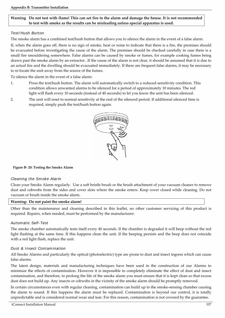
Appendix B: Transmitter Installation
iConnect Installation Manual
107
Warning Do not test with flame! This can set fire to the alarm and damage the house. It is not recommended to test with smoke as the results can be misleading unless special apparatus is used.
Test/Hush Button
The smoke alarm has a combined test/hush button that allows you to silence the alarm in the event of a false alarm. If, when the alarm goes off, there is no sign of smoke, heat or noise to indicate that there is a fire, the premises should be evacuated before investigating the cause of the alarm. The premises should be checked carefully in case there is a small fire smouldering somewhere. False alarms can be caused by smoke or fumes, for example cooking fumes being drawn past the smoke alarm by an extractor. . If the cause of the alarm is not clear, it should be assumed that it is due to an actual fire and the dwelling should be evacuated immediately. If there are frequent false alarms, it may be necessary to re-locate the unit away from the source of the fumes. To silence the alarm in the event of a false alarm: 1. Press the test/hush button. The alarm will automatically switch to a reduced sensitivity condition. This
condition allows unwanted alarms to be silenced for a period of approximately 10 minutes. The red light will flash every 10 seconds (instead of 40 seconds) to let you know the unit has been silenced.
2. The unit will reset to normal sensitivity at the end of the silenced period. If additional silenced time is required, simply push the test/hush button again.
Figure B- 20: Testing the Smoke Alarm
Cleaning the Smoke Alarm
Clean your Smoke Alarm regularly. Use a soft bristle brush or the brush attachment of your vacuum cleaner to remove dust and cobwebs from the sides and cover slots where the smoke enters. Keep cover closed while cleaning. Do not vacuum or brush inside the smoke alarm.
Warning: Do not paint the smoke alarm!
Other than the maintenance and cleaning described in this leaflet, no other customer servicing of this product is required. Repairs, when needed, must be performed by the manufacturer.
Automatic Self-Test
The smoke chamber automatically tests itself every 40 seconds. If the chamber is degraded it will beep without the red light flashing at the same time. If this happens clean the unit. If the beeping persists and the beep does not coincide with a red light flash, replace the unit.
Dust & Insect Contamination
All Smoke Alarms and particularly the optical (photoelectric) type are prone to dust and insect ingress which can cause false alarms. The latest design, materials and manufacturing techniques have been used in the construction of our Alarms to minimize the effects of contamination. However it is impossible to completely eliminate the effect of dust and insect contamination, and therefore, to prolong the life of the smoke alarm you must ensure that it is kept clean so that excess dust does not build up. Any insects or cobwebs in the vicinity of the smoke alarm should be promptly removed. In certain circumstances even with regular cleaning, contamination can build up in the smoke-sensing chamber causing the alarm to sound. If this happens the alarm must be replaced. Contamination is beyond our control, it is totally unpredictable and is considered normal wear and tear. For this reason, contamination is not covered by the guarantee.
Appendix B: Transmitter Installation
iConnect Installation Manual 108
Battery Replacement
When the battery power is low and replacement is necessary, the Alarm will “beep” and the red light will flash at the same time about once per minute. The battery must then be replaced. Replace the battery if the alarm does not sound when the Test Button is pressed. For maximum reliability, replace the battery at least once a year. After replacing the battery, press the test button to check that the alarm is functioning correctly.
End of Life
The entire Smoke Alarm must be replaced if: (i) The unit is installed for over 10 years (check the replacement year marked on the side of the unit). (ii) The unit fails to sound the horn loudly when the test button is pressed. (iii) The unit is giving a short beep every 40 seconds and the red light flashes at the same time for longer than 1 hour. If the unit beeps without the red light flashing at the same time, see Automatic Self-Test above.
Troubleshooting
Alarm Sounds For No Apparent Reason
Check for fumes, steam, etc. from kitchen or bathroom. Paint and other fumes can cause nuisance alarms. Check for any sign of contamination such as cobwebs or dust and clean the alarm as described on the previous page if necessary. Press the test/hush button on the unit causing the alarm – this will silence the smoke alarm for 10 minutes.
The Alarm Fails to Sound when the Test Button is Pressed
Check the age of the unit - see the “replace by” label on base of unit. Check the battery snaps are firmly connected – see Figure B- 20.
Limitations of Smoke Alarms
Smoke alarms have significantly helped to reduce the number of fire fatalities in countries where they are widely installed. However independent authorities have stated that they may be ineffective in some circumstances. There are a number of reasons for this:
Smoke alarms will not work if the batteries are depleted or if they are not connected. Test regularly and replace the entire unit when it fails to operate.
Smoke alarms will not detect fire if sufficient smoke does not reach the alarm. Smoke may be prevented from reaching the Alarm if the fire is too far away, for example, if the fire is on another floor, behind a closed door, in a chimney, in a wall cavity, or if the prevailing air draughts carry the smoke away. Installing smoke alarms on both sides of closed doors and installing more than one smoke alarm as recommended in this leaflet very significantly improve the probability of early detection.
The smoke alarm may not be heard. A smoke alarm may not wake a person who has taken drugs or alcohol. Smoke Alarms may not detect every type of fire to give sufficient early warning. They are particularly
ineffective with: fires caused by smoking in bed, escaping gas, violent explosions. poor storage of flammable rags and/or liquids, (for example petrol, paint, spirits etc), overloaded electrical circuits, arson, children playing with matches.
Smoke Alarms do not last indefinitely. The manufacturer recommends replacement after 10 years as a precaution.

Appendix B: Transmitter Installation
iConnect Installation Manual
109
Keyfobs (EL-2611/EL-2714) The EL-2611 and EL-2714 are keyfob transmitters that are supported by the system.
Figure B- 21: Figure B.14: EL-2611 Figure B- 22: Figure B.15: EL-2714 Figure B- 23: Opening the EL-2714’s Casing
Registration Procedure
To register keyfobs: 1. From the Programming menu, select Devices, Keyfobs [912]. 2. Select the keyfob you want to register; the system initiates Registration mode. 3. Press a button, making sure that the keyfob’s LED lights up when the button is pressed. 4. Press the same button again. When Save? appears on the Control System’s LCD display, press .
EL-2611
The EL-2611 is a one-button transmitter that generates a Medical alarm when pressed. The transmitter is water resistant and can be worn around the neck. Its large button makes it ideal for elderly or sight-impaired users. When the battery is low, the EL-2611’s LED flashes during transmission and a Low Battery signal is sent to the receiver. When either of these two indications is observed, replace the unit.
EL-2714
The EL-2714 is a four-button keyfob transmitter that offers a number of functions including arm, disarm and SOS Panic. When the battery is low, the EL-2714’s LED flashes during transmission and a Low Battery signal is sent to the receiver. When either of these two indications is observed, replace the batteries. Note: Batteries must be replaced within seven days of receiving a low battery indication. The estimated
battery life is 2 years (avg. 4 activations per day).
EL-2714 complies with EN-50131 Grade 2 Class II Power Supply Type C.
To replace the battery: 1. Insert a small screwdriver into the pry-off slot – see p. 109, Figure B- 23. Carefully twist the screwdriver
to separate the front and back of the casing. 2. Observing correct polarity, replace the battery (3V lithium, size: CR2032). 3. Close the casing making sure that the front and back click shut.
Wireless Terminal (EL-2724) The EL-2724 Wireless Terminal has a large LCD display showing arming status, alerts and system trouble, battery status, and time. The terminal also provides memo recording options, control over up to 16 home automation devices, and panic alarm function. You can arm and disarm the system using the Smartkey. The following procedure explains the installation of the EL-2724 and its two-way registration to the receiver. For further information regarding the EL-2424 maintenance and specifications, refer to the installation instructions provided with this product.

Appendix B: Transmitter Installation
iConnect Installation Manual 110
Figure B- 24: Plugging in the On-Board Transmitter
Figure B- 25: Figure B.18: AC Connection
Figure B- 26: Rear View
Connecting the AC and Battery power:
1. Open the Battery Compartment to gain access to the batteries and AC power connector – see p. 110, Figure B- 26. Below the batteries you will see the J1 9VDC connector – see p. 110, Figure B- 26.
2. Connect the Adaptor 230/9Vto the J1 9VDC connector of the EL-2724 observing the correct polarity – see p. 110, Figure B- 25.
3. Install the batteries (Model No. BT1218) observing correct polarity. Note: If the AC power has been applied for 48 hours but the Battery Status icon is still showing "low battery"
, replace the batteries as explained above.
RF Transmitter
To support the EL-2724, the Control System’s main board must have the plug-in RF transmitter (ELPN 5200736) installed. Plug the on-board transmitter into the Control System’s main board as shown in p. 110, Figure B- 24.
Setting the Control System Parameters to Support the EL-2724
On the Control System, enter the installer code and make the following settings: 1. Set the Wireless siren type [9152] to 2-way siren/KPD. 2. Set the Wireless siren Exit tones to Wireless siren [9311], select Enabled. 3. Set the Wireless siren Entry tones to Wireless siren [9321], select Enabled. 4. Set the Wireless siren Arm tones to Wireless siren [9331], select Enabled. 5. Set the Wireless siren Disarm tones to Wireless siren [9341], select Enabled. EL-2724 is a two-way device that requires two registration procedures. First, register the Control System to the EL-2724, then register the EL-2724 to the Control System.
Control system registration to the EL-2724
Registration of the Control System to the EL-2724 allows the EL-2724 to recognize transmissions from the Control System. There is a five-minute time limit for the Control System registration to the EL-2724. The time starts to count down when you power up the system.
PLU
G-I
N T
X

Appendix B: Transmitter Installation
iConnect Installation Manual
111
To register the Control System to the EL-2724: 1. Set the EL-2724 to registration mode. To do so, press the "1", "3", and "5" keys on the EL-2724
simultaneously; the buzzer sounds three short tones and both LEDs flash to indicate that it is in Registration mode.
Note: If the EL-2724 does not enter Registration mode, reset the EL-2724 and try again. To reset the EL-2724, disconnect the power, wait for ten seconds and re-apply power.
2. On the Control System, perform the Wireless siren test [703] twice (press twice). Each time a transmission is received, the EL-2724 sounds one long tone. After the second transmission is received by the EL-2724, both LEDs stop flashing to indicate that the Control System was registered successfully and Registration mode has been terminated.
EL-2724 Registration to the Control System
EL-2724 Registration to the Control System allows the system to recognize transmissions from the EL-2724. To register the EL-2742 to the Control System: 1. Set the Control System to Registration mode. [913KP# (1-4)]. 2. Send two transmissions by pressing the cancel button on the EL-2724 twice. 3. Confirm registration by pressing on the Control System. Note: After registration, the Control System transmits user code data to the EL-2724. This data transmission
also occurs after each user code's editing and after each EL-2724 reset or Control System reset. While the EL-2724 is receiving user code list updates, both LEDs and the backlight flash, the LCD’s clock display flashes 18:88, and the EL-2724 is temporarily locked. This process may take up to two minutes.
Smartkey Registration (optional)
For information on registration and deletion, see p. 43, 7.2. Wireless Devices. For descriptor editing, see p. 43 7.1 Device Descriptors.
Wireless Keypad (EL-2640) The EL-2640 is a one-way wireless keypad primarily designed as an additional arming station, including three arming keys that enable Full, Part/Partition 1 or Perimeter/Partition 2 arming modes. Pressing the Full and Perimeter buttons simultaneously generates an SOS panic alarm. Additionally, the keypad may be used to control Home Automation modules and PGM output. A slide-out reference card on the rear of the EL-2640 can be used for writing essential information such as Home Automation module allocation.
Figure B- 27: EL-2640 Figure B- 28: EL-2640 (Battery Cover Off)
Note: Do not write user codes on the reference card.
Registration Procedure
To register wireless keypads: 1. From the Programming menu, select Devices, Keypads [914]. 2. Select the keypad you want to register; the system initiates Registration mode.
9V Alkaline Battery

Appendix B: Transmitter Installation
iConnect Installation Manual 112
3. Press a button on the keypad making sure that a LED lights up when the button is pressed. 4. Press the same button again. When Save? appears on the Control System’s LCD display, press .
Battery Replacement (EL-2640)
When the battery is low, the EL-2640’s LED flashes during transmission. Every time a key is pressed, one of the battery status LEDs is lit. When the battery needs replacement, the red Low Battery LED is lit. To replace the battery: 1. Insert a small screwdriver into the pry-off slots at the bottom of the unit and twist to remove the back
cover. 2. Observing correct polarity, replace the battery (9V, alkaline – Eveready 522). 3. Replace the battery cover making sure that the two covers clicks shut.
Flood Sensor (EL-2661) The EL-2661 is an indoor flood sensor and transmitter intended for installation adjacent to hot water heaters, washing machines, central air conditioner condenser pans and anywhere prone to damage caused by an undetected water leak. In the event of flooding or leakage, the EL-2661 notifies the control System after detecting the presence of water for a period of at least 30 seconds.
Figure B- 29: EL-2661 Transmitter (Cover Off)
Caution: Batteries must be replaced within seven days of receiving a low battery indication. The estimated battery life is 4 years (avg. 25 activations per day).
Installation Procedure
1. To open the transmitter’s housing, insert a small screwdriver at the bottom of the unit between the front and back cover and twist the screwdriver to release the cover.
2. Remove the divider separating the battery from the contacts on the battery holder. When you apply power and the Tamper switch is open, the EL-2661 enters Test mode during which a transmission is sent every few seconds. You can terminate Test mode by closing the Tamper switch. Test mode is automatically terminated after approximately five minutes.
Note: Due to the occurrence of voltage delay in lithium batteries that have been in storage, the batteries may initially appear to be dead. In this case, leave the unit in Test mode for a few minutes until the battery voltage level is stabilized.
3. From the Programming menu, select Devices, Zones [911]. 4. Select the zone to which you want to register the transmitter; the system initiates Registration mode. 5. When Save? appears on iConnect LCD display, press . 6. After registration, press the EL-2661’s tamper switch to terminate Test mode.
Battery Holder
Antenna
LED Indicator
Location of wiring
knockout
Tamper Switch
PCB Release Tab
TerminalBlock

Appendix B: Transmitter Installation
iConnect Installation Manual
113
7. Choose a mounting location. The transmitter should be positioned in a vertical position high on the wall in order to optimize reception. The sensor should be placed in a position where water will accumulate rapidly in the event of a flood.
8. Before permanently mounting the unit, test the transmitter from the exact mounting position. 9. To remove the PCB, press the PCB release tab, carefully lift the board and slide the board away from
the back cover. Caution: When handling the PCB, do not apply pressure on the antenna. 10. Knockout the wiring hole in the back cover. 11. Mount the back cover to the wall using two screws and replace the PCB. Use #6 x 3/4" countersunk
wood screws (ISO 7050 - ST3.5 x 22) or similar countersunk screws so that the screw head will not touch the PCB – see p. 97, Figure B- 8.
12. Thread the sensor’s cable through the wiring hole. 13. Connect the sensor’s cable to the terminal block as shown in Figure B- 29 (p. 112). 14. Replace the PCB inside the back cover making sure that it clicks into place. 15. Before permanently mounting the sensor, place a wet rag over the terminals (located on the
bottom of the sensor). The EL-2661 transmits an alarm 30 seconds after detecting the presence of water. This 30-second delay verifies that the alarm is caused by a significant amount of water and is designed to prevent false alarms caused by humidity or condensation. Similarly, the EL-2661 sends a restore signal 30 seconds after the sensor’s terminals are dry. When the Tamper switch is open, the 30-second delay is canceled in order to speed up the test procedure. Make certain that the LED is lit during transmissions.
Note: The LED indicator does not function when the Tamper switch is closed. 16. Fix the sensor to the floor using the two screws, spacers and wall anchors provided. Alternatively, you
can fix the sensor to the floor using the double-sided adhesive tape provided – see the following section.
17. Close the front cover of the transmitter.
Sensor Installation with Double-sided Adhesive Tape
If using double-sided adhesive tape to install the sensor, perform the following procedure for best results: 1. Clean all surfaces using a low strength solvent such as isopropyl alcohol to ensure that the surfaces are
clean, dry and grease-free. 2. Peel away the backing from the pieces of adhesive tape and attach them to the underside of the sensor. Note: Do not touch the adhesive with your fingers. 3. Peel away the backing from the other side of the adhesive tape. 4. Fix the sensor to the floor by firmly applying pressure for a few seconds.
Repeater (EL-2635) The EL-2635 is a wireless repeater designed to extend the range of wireless devices registered to the Control System. Up to four repeaters can be registered to the Control System with 32 transmitters registered to each repeater. The repeater is powered by either 9VACwith a 6V rechargeable backup battery pack or 12VDC. Registration and maintenance tests are performed using a plug-in LCD programming keypad that provides a comprehensive interface to the repeater.

Appendix B: Transmitter Installation
iConnect Installation Manual 114
Figure B–30: Typical Single Repeater Application
Installation Procedure
1. Register all wireless devices to the iConnect Control System – see p. 43, 7.2.1 Registering Wireless Devices.
2. Define the Repeater option for each zone that is intended to transmit via the repeater as "Use Repeater" – see p.47, 7.3.8 Repeater.
3. Open the EL-2635’s plastic housing. To do so, remove the two cover screws and lift the front cover away from the base.
Figure B- 31: EL-2635 (cover removed)
4. Connect the antenna provided to the antenna connector. 5. Connect the backup battery pack to the Battery connector. 6. Connect a to the Power Input terminal block (polarity is not important when connecting AC to the
terminal block). 7. All registration and test functions, described in the following sections, are performed from the LCD
programming keypad model no. 5200250 shown in Figure B- 32 (p. 115). Connect the programming keypad to the Programming Keypad connector.
Note: The repeater’s programming keypad is not able to operate on battery power only. 8. Register the repeater to the Control System using the following procedure:
a. Set the Control System to Registration mode as follows:
a. From the Programming menu, select Devices, Repeaters [914].
b. Select the repeater you want to register (1-4).
c. From the repeater’s sub-menu, select Register [#1]. b. Send two Status transmissions from the repeater as follows:
Antenna Connector
Programming Keypad Connector
Lower Mounting
Hole
Upper Mounting Hole
Lower Mounting Hole
LED Indicator
Receiver
Tamper Switch
AC PowerProtection
Fuse
Upper Mounting
Hole
TransmitterFlash Programming Connector
Power Input Terminals
Wiring Hole

Appendix B: Transmitter Installation
iConnect Installation Manual
115
a. On the LCD programming keypad, press until 5. STS Transmit appears on the display.
Figure B- 32: LCD Programming Keypad
b. Press .
c. Press again. c. Confirm registration to the Control System as follows: d. When Save? appears on the Control System’s LCD display, press .
9. Test the repeater from the required mounting location before permanently mounting the unit. 10. Mount the base to the wall using four screws and replace the front cover.
Registering Transmitters to the Repeater
You can register up to eight transmitters to the EL-2635 repeater.
Figure B- 33: Transmitter Registration Procedure Figure B- 34: Transmitter Deletion Procedure
Figure B- 35: TX List Procedure Figure B- 36: TX Test Procedure
Caution: Do not register the same transmitter to more than one repeater. To register transmitters to the repeater:
1. On the LCD programming keypad, press until 4. TX Register appears on the display. 2. Press ; New Device appears on the display. 3. Press again; Transmit 1 appears on the display. 4. Send two transmissions from the device you want to register. 5. When the transmitter number and Save? appear on the display, press to confirm registration. Note: The EL-2635 repeater automatically allocates a transmitter number to each newly registered device.
Write this number and the zone number on the sticker provided with the sensor and stick it inside the transmitter's cover for future reference.

Appendix B: Transmitter Installation
iConnect Installation Manual 116
6. After you have confirmed registration, the display returns to New Device. Press to register another device or to exit Registration mode.
Deleting Registered Transmitters
To delete transmitters from the repeater’s register: 1. On the LCD programming keypad, press until 3. TX Delete appears on the display. 2. Press ; the first transmitter in the list appears on the display. 3. Use the arrow navigation keys (5/6) to scroll to the transmitter you want to delete. 4. Press to select the transmitter. 5. Press again for confirmation; the transmitter is deleted. 6. Select another transmitter to delete or press to exit.
Installer Utilities
The EL-2635 repeater offers two installer utilities that serve as a valuable aid during installation and maintenance.
TX List
The TX List is a scrollable inventory of all transmitters that are registered to the repeater and their last reported signal strength. To view the TX list: 1. Press until 1. TX List appears on the display. 2. Press ; the first transmitter in the list is displayed. 3. Use the arrow navigation keys ( / ) to scroll through the list. 4. Press to exit the list.
TX Test:
TX Test is a utility that enables you to identify transmitters that are registered to the repeater and to test their signal strength. To perform the TX test: 1. Press until 2. TX Test appears on the display. 2. Press . 3. Activate a transmitter; the transmitter number, type and signal strength are displayed. 4. Press to exit TX Test mode.

Appendix B: Transmitter Installation
iConnect Installation Manual
117
Transmitter Specifications The technical specifications for the transmitters that appear in this appendix are listed below. All transmitters are available in 868.35, or 433.92MHz (optional) FM frequencies.
EL-2600 PIR Antenna: Built-in Whip Power: 3.6V ½ AA Lithium Battery Current Consumption: 30mA (transmission) 6µA (standby) Pyroelectric Sensor: Dual Element Maximum Coverage: 46 x 46ft (14 x 14m) Pulse Count: 1, 2 or 3 Jumper Selectable LED Indicator: Jumper Selectable Adaptive Temperature Compensation RFI Immunity: 30V/m Operating Temperature: 14 to 140°F (-10 to 60°C) Fire Protection: ABS Plastic Housing Dimensions: 4.33"H x 2.36"W x 1.77"D (110 x 60 x 45mm) EL-2600PI PIR Antenna: Built-in Whip Power: 3.6V ½ AA Lithium Battery Current Consumption: 30mA (transmission), 6µA (standby) Pyroelectric Sensor: Dual Element Maximum Coverage: 39.3 x 39.9ft (12 x 12m) Pulse Count: 1, 2 or 3 Jumper Selectable LED Indicator: Jumper Selectable Adaptive Temperature Compensation RFI Immunity: 30V/m Operating Temperature: 14 to 140°F (-10 to 60°C) Fire Protection: ABS Plastic Housing Dimensions: 4.33"H x 2.36"W x 1.77"D (110 x 60 x 45mm) EL-2645 PIR Antenna: Built-in Whip Power: 3.6V ½ AA Lithium Battery Current Consumption: 30mA (transmission) 12µA (standby) Pyroelectric Sensor: Dual Element Maximum Coverage: 46 x 46ft (14 x 14m) Pulse Count: 1, 2, 3 or Adaptive LED Indicator: Selectable Adaptive Temperature Compensation RFI Immunity: 30V/m Operating Temperature: 14 to 140°F (-10 to 60°C) Fire Protection: ABS Plastic Housing Dimensions: 4.33"H x 2.36"W x 1.77"D (110 x 60 x 45mm) EL-2645PI PIR Antenna: Built-in Whip Power: 3.6V ½ AA Lithium Battery Current Consumption: 30mA (transmission), 12µA (standby) Pyroelectric Sensor: Dual Element Maximum Coverage: 39.3 x 39.9ft (12 x 12m) Pulse Count: 1, 2, 3 or Adaptive LED Indicator: Selectable Adaptive Temperature Compensation RFI Immunity: 30V/m Operating Temperature: 14 to 140°F (-10 to 60°C) Fire Protection: ABS Plastic Housing Dimensions: 4.33"H x 2.36"W x 1.77"D (110 x 60 x 45mm) EL-2745 PIR Antenna: Built-in Internal Whip Frequency: 868.35MHz*, 433.92MHz, or 418 MHz Power: 3.6V ½ AA Lithium Battery Caution: Fire, explosion and severe burn hazard! Do not recharge, disassemble or heat above 100°C (212F). Current Consumption: 30mA (transmission) 12µA (standby) Pyroelectric Sensor: Dual Element Maximum Coverage: 14 x 14m Pulse Count: 1, 2, 3 or Adaptive (selectable) LED Indicator: Selectable Digital Adaptive Temperature Compensation RFI Immunity: 30V/m Operating Temperature: -10 to 60°C Fire Protection: ABS Plastic Housing Dimensions: 110 x 62 x 50mm
Screw recommended: ST 2.9x22 DIN 7981 (ISO 7049) * Complies with EN-50131 2-2 Grade 2 Class II, Power Supply Type C EL-2745PI PIR Antenna: Built-in Internal Whip Frequency: 868.35MHz*, 433.92MHz, or 418 MHz Power: 3.6V ½ AA Lithium Battery Caution: Fire, explosion and severe burn hazard! Do not recharge, disassemble or heat above 100°C (212F). Current Consumption: 30mA (transmission)/12µA (standby) Pyroelectric Sensor: Dual Element Maximum Coverage: 12 x 12m Pulse Count: 1, 2, 3 or Adaptive (selectable) LED Indicator: Selectable Digital Adaptive Temperature Compensation RFI Immunity: 30V/m Operating Temperature: -10 to 60°C Fire Protection: ABS Plastic Housing Dimensions: 110 x 62 x 50mm Screw recommended: ST 2.9x22 DIN 7981 (ISO 7049) * Complies with EN-50131 2-2 Grade 2 Class II, Power Supply Type C EL-2601 Magnetic Contact/EL-2602 Universal Transmitter Antenna: Built-in Whip Power: 3.6V ½ AA Lithium Battery Current Consumption: 25mA (transmission) 10µA (standby) Loop Input Voltage Range for EL-2602: 0-15VDC/AC (peak to peak) RFI Immunity: 40V/m Operating Temperature: 32 to 140°F (0 to 60°C) Dimensions: 2.5"H x 1.18"W x 0.9"D (65 x 30 x 25mm) EL-2603 Smoke Detector Antenna: Built-in Internal Whip Current Consumption: 30mA (transmission), 20µA (standby) Power: 9V Alkaline Battery RFI Immunity: 40V/m Operating Temperature: 32 to 140°F (0 to 60°C) Dimensions: 5.43"H x 4.65"W x 1.73"D (138 x 118 x 44mm) EL-2603EN Smoke Detector Antenna: Built-in Internal Whip Frequency: 868.35MHz FM Power: 9V Alkaline Battery Current Consumption: 27mA (transmission) 10μA (standby) Humidity Range: 15%-95% RH (non-condensing) LED Indication: Power, Trouble and Alarm (Red) RF transmission (Blue) Alarm: 85dB @ 3m RFI Immunity: 10V/m Operating Temperature: 0-55°C EL-2606 Glassbreak Sensor Antenna: Built-in Whip Power: 3.6V ½ AA Lithium Battery Current Consumption: 25mA (transmission) 30µA (standby) Warning: Fire, explosion and severe burn hazard! Do not recharge, disassemble or heat above 100°C (212 °F). Microphone: Omni-directional electret Maximum Range: 6m (plate, tempered, laminated and wired glass) 3.65m (armor-coated glass) RFI Immunity: 20V/m Operating Temperature: 32 to 122°F (0 to 50°C) Dimensions: 3.14"H x 4.25"W x 1.69"D (80 x 108 x 43mm) EL- 2661 Flood Sensor Antenna: Built-in Internal Whip Frequency: 868.35, 433.92 or 418MHz FM Power: 3.6V ½ AA Lithium Battery BT5055

Appendix B: Transmitter Installation
iConnect Installation Manual 118
Warning: Fire, explosion and severe burn hazard! Do not recharge, disassemble or heat above 212°F (100°C) Current Consumption: 25mA (transmission) 10µA (standby) RFI Immunity: 40V/m Cable Length: 2.4m Operating Temperature: 32 to 140°F (0 to 60°C) Dimensions: 2.5"H x 1.18"W x 0.9"D (65 x 30 x 25mm) EL-2611 Keyfob Antenna: Built-in Whip Current Consumption: 16mA (transmission), 0µA (standby) Power: Non-replaceable battery RFI Immunity: 40V/m Operating Temperature: 32 to 140°F (0 to 60°C) Dimensions: 2.36"H x 1.57"W x 0.59"D (60 x 40 x 15mm) EL-2714 keyfob Antenna: Printed on PCB Power: 3V Lithium Battery Operating Temperature: 32 to 140°F (0 to 60°C) Dimensions: ø1.77" X 0.51"H (45ø x 13mm) EL-2724 Wireless Terminal Antenna: Printed on PCB Frequency: 868.35MHz, 433.92MHz or 418MHz FM Current Consumption: 55mA (transmission) 25mA (standby)
Power: 9VDC (supplied 230V/9V Adaptor) Battery backup by 4x1.2V 1600mAh NiMH batteries RFI Immunity: 40uV/m Operating Temperature: 32 to 140°F (0 to 60°C) Dimensions: 5.1"H x 4.3"W x 1.1"D (130 x 110 x 28mm) EL-2640 Wireless Keypad Antenna: Printed on PCB Current Consumption: 25mA (transmission)3µA (standby) Power: 9V Alkaline Battery RFI Immunity: 40V/m Operating Temperature: 32 to 140°F (0 to 60°C) Dimensions: 5.0"H x 1.9"W x 1.1"D (128 x 49 x 27mm) EL-2635 Repeater Frequency: 868.35MHz, 433.92MHz or 418MHz FM Antenna: External Whip Operating Voltage: 9VAC (No. 1332) or 12VDC Backup Battery: 6V/850mAh (ELPN BT5757) (5 x 1.2V Ni-MH rechargeable cells, size AAAL, BT2635) Current Consumption: 100mA max. (during transmission) Number of Transmitters: 32 max. Tamper Protection: Front Cover (N.C.) Operating Temperature: 32 to 140°F (0 to 60°C) Dimensions: 4.29"H X 4.84"W X 1.1"D (123 x 109 x 27mm)
Lithium Batteries
Fire, explosion and severe burn hazard!
When handling lithium batteries follow the listed precautions: • Do not recharge. • Do not deform or disassemble. • Do not heat above 100°C or incinerate.
Due to the occurrence of voltage delay in lithium batteries that have been in storage, the batteries may initially appear to be dead. In this case, leave the unit in Test mode or Radio mode for a few minutes until the battery voltage level is stabilized.
!

Appendix C: Web User Application
iConnect Installation Manual
119
Appendix C: Web User Application The Web Application provides a full interface to all of the system’s user functions. Via the Web, the end user can perform a wide range of tasks such as arm/disarm, zone bypass, user code management and home automation control. You can also access the Web User Application from your cellular phone or PDA using the WAP protocol.
Log In Page This application is usually part of the service provider’s Web site and requires the end user to log in to gain access to the page. To enter the Web Application, on your browser enter the Web page address supplied by your WEB service provider and press Go. You will see the Login Page.
Figure C- 1: Login Page
To login to the Web Application, enter your user name and password supplied by your WEB service provider, and the passcode which is your User Code, then click the Enter button. Caution: For your system security reasons, you must change the password immediately at first login. You
can change your password on the Change Password page that is accessible from the Settings menu. Your new password should be no less than six characters and must start with a letter – see p. 122, Change Password.
The Main Page After logging in, your system’s home page (Main Page) is displayed.
Figure C- 2: The Main Page
Menu Bar
Status Bar
Workspace

Appendix C: Web User Application
iConnect Installation Manual 120
When using WAP service of your cellular phone, the main page looks the following way:
Figure C- 3: The Main Page (WAP)
Menu Bar
The Menu Bar includes the Main Menu, arm/disarm options list and the Log Off button. The Main Menu offers links to various pages in the Web Application. Use the Logoff button on the right side menu to properly close the session. The following options are available from the Main Menu:
Home – pressing the Home button allows the user to return to the Main page at any time Automation – allows control or scheduling of automated lights and appliances. Video – provides access to view streaming video from IP cameras. My Account – offers various options including user code and contact management, event log viewing
and zone bypass. Help – offers online explanations on how to use the Web Application plus FAQ and customer support
options.
Status Bar
The Status bar displays information on your system’s status and the name of the user currently logged in. Above the status bar, the time when the system status display was last updated is shown. This information is displayed according to the local time at the control system. When logging into the WUApp with a GPRS Control System, the system status refreshes automatically, and can be refreshed manually as well. To refresh the current system status, click the Refresh Status button on the right-hand side of the Status bar.
Workspace
The workspace offers additional links to the following pages of the application: Users and Codes, History, Automation, Alerts, Change Password, Video. When you choose a page, either from the Main Menu, or from the workspace, the page is displayed in the workspace. For example, if you choose Automation from the Main Menu, a list of automated appliances is displayed in the workspace. Note: SMS alerts relate only to SMS sent from ELAS (WEB User Application).

Appendix C: Web User Application
iConnect Installation Manual
121
Options Available from Main Page
Arm/Disarm
Figure C- 4: Arm/Disarm Page
You can arm and disarm the system using the Arm/Disarm drop-down box (upper-right part of the page) or using the buttons in the System Operation Area. The Web Application allows you to arm and disarm your system via the Web Application using any of the available arming methods. It is important to note that when you arm using the Web application, the system is armed with the programmed delay. 1. On the Status Bar below on the page you can see the current status of the system (in our example it is
Disarmed and System Ready, which means that the system and all the detectors are working properly and there are no events to report).
2. It is possible to check if there were alarms in the system – see p. 125, History.
System Users and Codes
In this area you can add, delete, or change users and the User Codes for your system (for example, add codes for family members). 1. On The Main Page menu, click Settings.
Figure C- 5: Settings Button
2. Click System Users and Codes, the following page appears:
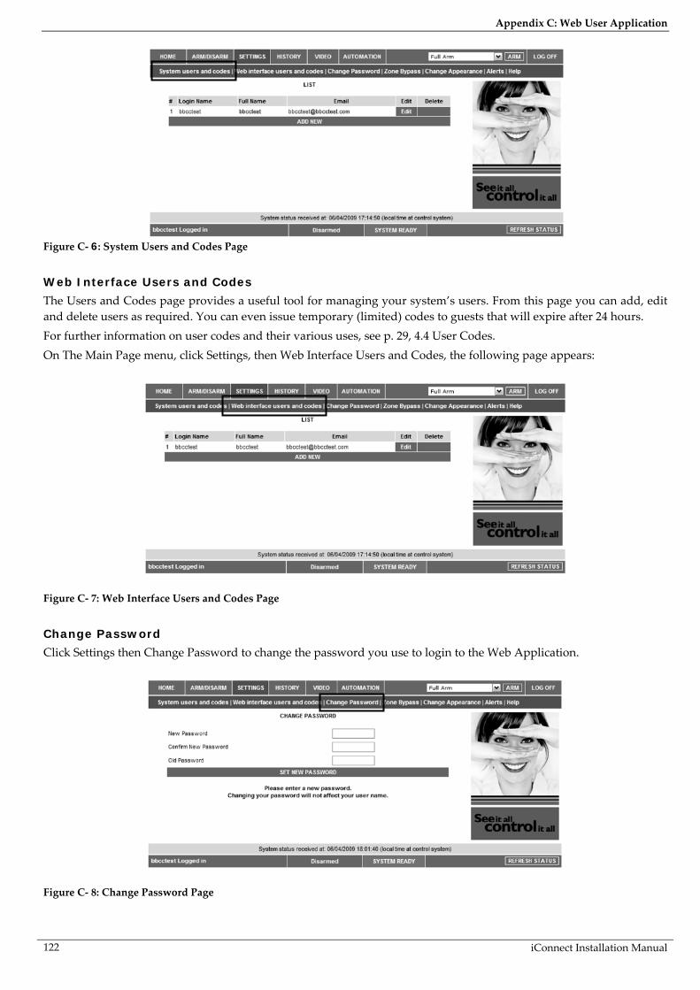
Appendix C: Web User Application
iConnect Installation Manual 122
Figure C- 6: System Users and Codes Page
Web Interface Users and Codes
The Users and Codes page provides a useful tool for managing your system’s users. From this page you can add, edit and delete users as required. You can even issue temporary (limited) codes to guests that will expire after 24 hours. For further information on user codes and their various uses, see p. 29, 4.4 User Codes. On The Main Page menu, click Settings, then Web Interface Users and Codes, the following page appears:
Figure C- 7: Web Interface Users and Codes Page
Change Password
Click Settings then Change Password to change the password you use to login to the Web Application.
Figure C- 8: Change Password Page

Appendix C: Web User Application
iConnect Installation Manual
123
Zone Bypass
On The Main Page menu, click Settings then Zone Bypass to bypass certain zones in your home that you don't want to receive event messages from – see p. 29, Zone Bypassing/Unbypassing. Select the checkboxes for the zones you want to bypass.
Figure C- 9: Zone Bypass Page
Change Appearance
On The Main Page menu, click Settings then Change Appearance to change the color scheme of your account.
Figure C- 10: Change Appearance Page
Alerts
The Alerts page allows you to enter the details of contacts you wish to be informed when events occur in your system. For example, you can enter your own email address and/or cellular phone number so that you will receive email or SMS notification in the event of an alarm. This area allows you to program where to send the alerts on home events (arming, disarming, alarm etc.) The events can be reported via email or your cellular phone. 1. On The Main Page menu, click the Alerts area.

Appendix C: Web User Application
iConnect Installation Manual 124
Figure C- 11: Alerts Area
The following page appears:
Figure C- 12: Alerts Page
2. Press Add new to add email addresses or cellular telephone numbers for the alert messages.
Figure C- 13: Add New Contact Page
3. In the Contact Name field, enter the name of the contact to receive alerts. 4. In the Email Address field, enter the email address for email alerts. 5. In the Cellular Phone # field, enter the cellular phone number for SMS alerts. 6. To start receiving the events messages, in the area below, select the checkboxes according to the event
type and message type you prefer (email or SMS).

Appendix C: Web User Application
iConnect Installation Manual
125
7. Test the alerts you have programmed by clicking the Test button on the Alerts page near the newly added alert.
History
The History page enables you to view the system’s event log. The events are arranged in a table that offers the advantage of allowing you to view a large number of events at once. In addition to viewing the event log, you may also save the log to a file (HTML, PDF or RTF) or print the log. For further details on how to use the Web Application, refer to the Help menu included in the application.
On The Main Page menu, click History, the following page appears:
Figure C- 14: History Page
You can save or print the LOG from this page.
Automation
The Web Application allows you to control and schedule automated lights and appliances in your home. The application offers a comprehensive interface that enables you to view the settings for all of your automated devices at once. Additionally, you can add, edit or delete devices from the comfort of your PC. Discuss this capability with your security service provider to determine if it is applicable to your system – see p. 41 Home Automation and PGM Control.
On The Main Page menu, click Automation, the following page appears:
Figure C- 15: Automation Page
You can program turning the HA units on/off at specific hour/day of the week.

Appendix C: Web User Application
iConnect Installation Manual 126
Video Using IP video cameras installed in your home, the Web Application enables you to view streaming video over the Web in order to check your home and family while you are away. Discuss this capability with your security service provider to determine if it is applicable to your system.

Appendix D: Installing IP Cameras (Relevant to GPRS/Ethernet & ELAS Configuration)
iConnect Installation Manual
127
Appendix D: Installing IP Cameras (Relevant to GPRS/Ethernet & ELAS Configuration) IP cameras installed on the protected site may be accessed by the user via the Web Application – see p. 119, Appendix C: Web User Application. For a list of supported IP cameras, please contact your distributor.
Figure D- 1: Typical IP Camera Installation
The following section gives an example installation procedure for one of our supported IP cameras. The exact procedure may vary depending on your router and camera model. For relevant and detailed installation procedure, please refer to the installation manual supplied with the camera and the router. To enable video monitoring using IP cameras, the following steps are required:
Port forwarding must be configured on the router to allow the user outside access to the IP camera. An administrator must enter the camera’s IP address and port in the Control System’s record in the
ELAS database.
Port Forwarding
The Broadband Router has an IP address that allows data to be sent and received over the Internet. The IP address is divided into ports. These ports are effectively the path through which the data is sent or received allowing multiple tasks to be performed simultaneously via the router. When a few IP network devices are connected to the router, to ensure a connection to the correct device you must configure the router’s Port Forwarding options. This allows data that has reached the router (with an external IP address) to reach its required destination on the internal network (i.e. behind the router).
IP Camera Installation
Figure D- 2: Connecting the IP Camera
To install an IP camera: 1. Connect the camera’s Ethernet port to the router. 2. Connect the camera to the power supply via the camera’s power jack; the camera waits to automatically
receive an internal IP address. When the camera receives an IP address, the camera indicates that it has connected (for example, a green flashing LED – refer to the camera manufacturer’s installation instructions for further details).
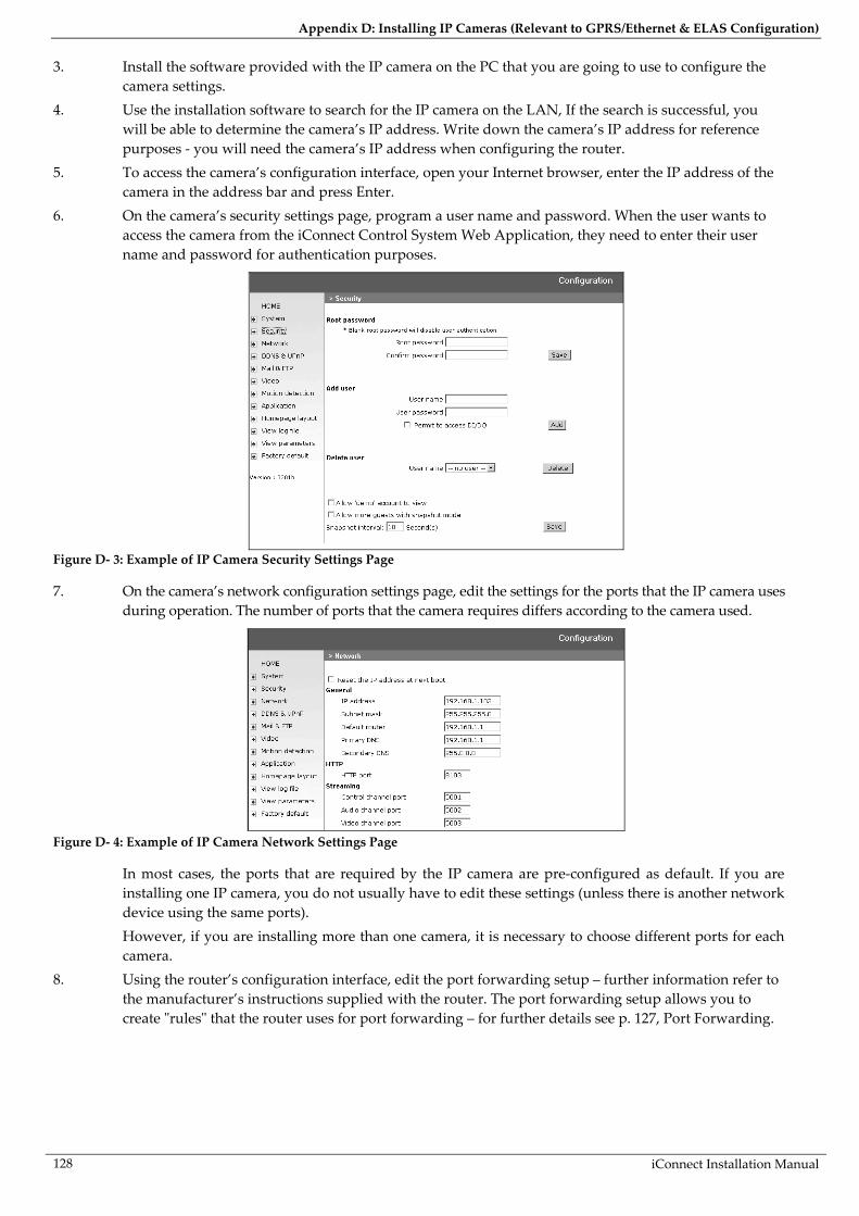
Appendix D: Installing IP Cameras (Relevant to GPRS/Ethernet & ELAS Configuration)
iConnect Installation Manual 128
3. Install the software provided with the IP camera on the PC that you are going to use to configure the camera settings.
4. Use the installation software to search for the IP camera on the LAN, If the search is successful, you will be able to determine the camera’s IP address. Write down the camera’s IP address for reference purposes - you will need the camera’s IP address when configuring the router.
5. To access the camera’s configuration interface, open your Internet browser, enter the IP address of the camera in the address bar and press Enter.
6. On the camera’s security settings page, program a user name and password. When the user wants to access the camera from the iConnect Control System Web Application, they need to enter their user name and password for authentication purposes.
Figure D- 3: Example of IP Camera Security Settings Page
7. On the camera’s network configuration settings page, edit the settings for the ports that the IP camera uses during operation. The number of ports that the camera requires differs according to the camera used.
Figure D- 4: Example of IP Camera Network Settings Page
In most cases, the ports that are required by the IP camera are pre-configured as default. If you are installing one IP camera, you do not usually have to edit these settings (unless there is another network device using the same ports). However, if you are installing more than one camera, it is necessary to choose different ports for each camera.
8. Using the router’s configuration interface, edit the port forwarding setup – further information refer to the manufacturer’s instructions supplied with the router. The port forwarding setup allows you to create "rules" that the router uses for port forwarding – for further details see p. 127, Port Forwarding.

Appendix D: Installing IP Cameras (Relevant to GPRS/Ethernet & ELAS Configuration)
iConnect Installation Manual
129
Figure D- 5: Example of Router Port Forwarding Configuration Page
9. Configure port forwarding rules using the following guidelines: Create a separate rule for each port that is used by each camera. In the "Start" and "End" fields (sometimes labeled "Private" and "Public"), enter the same port
number in both fields. For example, if the HTTP Port is 8103, enter "8103" in both fields. Select the Protocol as "Both" (i.e. use both UDP and TCP protocols). Enter the IP address that was automatically allocated to the IP camera – see step 4 of this
procedure. For further information on how to install an IP camera and configure the router, refer to the manufacturer’s instructions that are supplied with both products.

Appendix E: Event Table*
iConnect Installation Manual 130
Appendix E: Event Table*
Burglary Description Restore SIA Contact ID Address Field
Alarm from Zone NBA 1130 Device Number
Zone Alarm Restore NBR 3130 Device Number
Zone Bypassed NUB 1570 Device Number
Zone Unbypassed NUU 3570 Device Number
Zone Tamper NTA 1137 Device Number
Zone Tamper Restore NTR 3137 Device Number
Zone Panic Alarm NPA 1120 Device Number
Zone Panic Restore NPR 3120 Device Number
Panic Alarm NPA 1120 Device Number
Tamper NTA 1137 Device Number
Tamper Restore NTR 3137 Device Number
Duress NHA 1121 —
Bell Cancel NBC 1521 User Number
Disarm after Alarm NOR 1458 User Number
Water Alarm NWA 1154 Device Number
Water Alarm Restore NWH 3154 Device Number
Environmental Alarm NUA 1150 Device Number
Environmental Alarm Restore NUH 3150 Device Number
Exit Error NEE 1457 User Number
Fire
Fire Alarm NFA 1110 Device Number
Fire Alarm Restore NFR 3110 Device Number
Gas Alarm NGA 1151 Device Number
Gas Alarm Restore NGH 3151 Device Number
Open/Close
Full Arm NCL 3401 User Number
Part Arm NCG 3456 User Number
Perimeter Arm NCG 3441 User Number
Disarm (entire system) NOP 1401 User Number
Partitioned Arm NCG 3400 User Number, Area** Number
Partitioned Disarm NOG 1400 User Number, Area Number
* = Events that are displayed in the event log only when viewed by the installer. ** Area number is 03 for Full, 01 For Part/ Partition 1, and 02 for Perimeter/ Partition 2.

Appendix E: Event Table*
iConnect Installation Manual
131
Service Description Restore SIA Contact ID Address Field
Edit User Code NJV 1462 User Number
Delete User Code NJX 3462 User Number
System Programming NLB 1627 —
End System Programming NLX 1628 —
Remote Programming NRB 1412 —
End Remote Programming NRS 3412 —
Walk Test NTS 1607 User Number
End Walk Test NTE 3607 —
Set Time NJT 1625 User Number
Set Date NJD 1625 User Number
Clear Log NLB 1621 User Number
Power Battery Low NYT 1302 Device Number
Battery Restore NYR 3302 Device Number
Transmitter Low Battery NXT 1384 Device Number
Transmitter Battery Restore NXR 3384 Device Number
AC Loss NAT 1301 Device Number
AC Restore NAR 3301 Device Number
Power up (user-log) NRR 3301 Device Number
Peripherals Media Loss NLT 1351 Device Number
Media Loss Restore NLR 3351 Device Number
Device Trouble NET 1330 Device Number
Device Trouble Restore NER 3330 Device Number
Transmitter Out of Synch. NUT 1341 Device Number
Transmitter Re-synch. NUR 3341 Device Number
CP Transmitter Out of Synch. NUT 1341 Device Number
CP Transmitter Re-synch. NUR 3341 Device Number
Supervision Loss NUS 1381 Device Number
Supervision Restore NUR 3381 Device Number
GSM Signal Level NYY 1605 Signal Level (0-9)
Zone Trouble NBT 1380 Device Number
Zone Trouble Restore NBJ 3380 Device Number
RF Jamming FM Jamming NXQ 1344 Device Number
FM Jamming Restore NXH 3344 Device Number
Medical Medical Alarm NMA 1100 Device Number
Medical Alarm Restore NMR 3100 Device Number
No Motion NNA 1102 Device Number

Appendix E: Event Table*
iConnect Installation Manual 132
Unclassified Events Description Restore SIA Contact ID Address Field
Periodic Test NRP 1602 —
No Arm NCD 1654 —
Cancel Report NOC 1406 —
Address Field
The address field provides additional information regarding the event. This information is forwarded as numeric data according to the following tables.
DEVICE NUMBER
Value Description
00 Control System
01-33 Zones
41-59 Keyfobs
65 Home Automation Module
77-80 Repeaters
81-84 Wireless Keypads
91 Front Panel Keypad
92-98 Hardwire Keypads
110 Wireless Siren
242 Communication Module
243 PSTN Communication Interface
244 Cellular Communication Interface
245 Ethernet Communication Interface
249 GPRS Communication Interface
USER NUMBER
Value Description
00 Control System
01-32 Users
34 Remote Access
41-59 Keyfobs
61-76 Smartkeys
81-84 Wireless Keypads
91 Front Panel Keypad
92-98 Hardwire Keypads

Appendix F: Zone Types
iConnect Installation Manual
133
Appendix F: Zone Types
Normal
A Normal zone is active when the system is armed. This zone generates a Burglary alarm instantly when triggered. Normal zones are designed for detectors installed inside the protected site or doors/windows that are never used to enter the premises.
Event Group: Burglary
Entry/Exit
When the system is armed, Entry/Exit zones initiate the entry delay when triggered. If the system is not disarmed by the time the entry delay expires, a Burglary alarm is generated. These zones are designed for detectors protecting the entrance to the protected site
Event Group: Burglary
Follower
If an Entry/Exit zone is triggered first, Follower zones do not generate an alarm when triggered during the entry delay. If the system is not disarmed by the end of the entry delay, the Follower zone generates an alarm. A Follower zone instantly generates an alarm if triggered when the entry delay is not active. These zones are designed for detectors protecting the area in which a keypad has been installed or the area crossed in order to reach the keypad.
Event Group: Burglary
Panic
Panic zones are always active. When a Panic zone is triggered, a Panic alarm is generated. This zone type is designed for panic buttons that may be pressed in a robbery situation. If the Bell option is disabled for Panic zones, in addition to the siren not sounding, all forms of alarm indication from the keypad are also disabled.
Event Group: Burglary
Medical
Medical zones are always active. When triggered, Medical zones generate a Medical alarm. These zones are used typically with panic buttons that may be pressed in the event of a Medical.
Event Group: Medical
Fire
Fire zones are always active. When triggered, Fire zones generate a Fire alarm. These zones are designed for use with smoke detectors and panic buttons that may be pressed in the event of a fire. A Fire zone always activates the siren even if the Bell option is programmed as disabled. Fire alarms sound a pulsating siren to distinguish them from other alarms.
Event Group: Fire
24Hr
24Hr zones are always active. When triggered, 24Hr zones generate a Burglary alarm. These zones are used for applications that require constant protection.
Event Group: Burglary
24Hr-X
The 24Hr-X zone is a future option that is not available in the current firmware. Event Group: Not applicable

Appendix F: Zone Types
iConnect Installation Manual 134
Gas
Gas zones are always active. In the event of a gas leak, these zones generate a Gas alarm. Gas zones are typically used with methane/propane/butane or carbon monoxide gas detectors. Gas alarms sound a distinctive siren pattern to easily distinguish them from other alarms. A gas alarm causes the siren to sound until the alarm is restored; the siren cut-off does not apply to gas alarms.
Event Group: Fire
Flood
Flood zones are always active. When triggered, Flood zones generate a Water alarm. These zones are designed for use with EL-2661 flood sensors.
Event Group: Burglary
Environmental
Environmental zones are always active. When triggered, these zones generate an Environmental alarm. These zones are designed for applications that monitor environmental conditions such as temperature or humidity. If the Bell option is enabled for Environmental zones, the system sounds trouble tones from the keypad. These tones are sounded until the user presses on their keypad. Environmental alarms are not affected by the expiry of the siren cut-off.
Event Group: Burglary
No Motion
No Motion zones are used to monitor the activity of disabled or elderly people. If a No Motion zone has not been triggered within a pre-defined period of time (0 to 72 hours), a No Motion event message is sent to the central station.
Event Group: Medical
Not Used
This zone type disables the sensor output. All alarm transmissions from the sensor are ignored though the sensor may still be used to activate HA units in Home Automation applications.
Event Group: Not applicable

iConnect Installation Manual
135
ELECTRONICS LINE 3000 Ltd. - LIMITED WARRANTY ELECTRONICS LINE 3000 Ltd. (hereafter "EL3K") warrants its products to be free from manufacturing defects in materials and workmanship for (Wireless – 12 months excluding batteries, Control Systems – 2 years, Dual Technology Detectors – 2 Years, PIR Detectors - 5 years) following the date of sale. EL3K will, within said period, at its option and in accordance with the terms of this Limited Warranty, repair or replace any product failing to operate correctly without charge to the original purchaser or user. In case of defect, contact the security professional who installed and maintains your security system. In order to exercise the warranty, the product must be returned by the user or purchaser, shipping costs prepaid and insured to EL3K. EL3K will not be responsible for any dismantling or reinstallation changes.
This warranty shall not apply to any equipment, or any part thereof, which has been repaired by others, improperly installed,
improperly used, abused, altered, damaged, subjected to acts of God, or on which any serial numbers have been altered, defaced or removed, or on a product in which the fault does not prevent the use of the product at the installation site, or in the system to which the product is connected.
There is no express or implied warranty of merchantability or warranty of fitness for a particular purpose. Any action for
breach of warranty, including but not limited to any implied warranty of merchantability, must be brought within the six months following the end of the warranty period. In no case shall EL3K be liable to anyone for any consequential or incidental damages for breach of this or any other warranty, express or implied, even if the loss or damage is caused by the EL3K's own negligence or fault.
In no event shall EL3K be liable for an amount in excess of EL3K's original selling price of the product, for any loss or damage,
whether direct, indirect, incidental, consequential, or otherwise arising out of any failure of the product. CONSEQUENTLY, EL3K SHALL HAVE NO LIABILITY FOR ANY PERSONAL INJURY, PROPERTY DAMAGE, OR OTHER LOSS BASED ON A CLAIM THE PRODUCT FAILED TO GIVE WARNING. EL3K's warranty, as herein above set forth, shall not be enlarged, diminished or affected by and no obligation or liability shall arise or grow out of EL3K's rendering of technical advice or service in connection with Buyers order of the goods furnished hereunder.
This warranty contains the entire warranty. Additionally, this warranty is in lieu of all other obligations or liabilities on the part
of EL3K It is the sole warranty and any prior agreements or representations, whether oral or written, are either merged herein or are expressly canceled. EL3K neither assumes, nor authorizes any other person purporting to act on its behalf to modify, to change, or to assume for it, any other warranty or liability concerning its products.
EL3K RECOMMENDS THAT THE ENTIRE SYSTEM BE COMPLETELY TESTED WEEKLY.
Warning: Despite frequent testing, and due to, but not limited to, any or all of the following: criminal tampering, electrical or
communications disruption, it is possible for the system to fail to perform as expected. EL3K does not represent that the product/system may not be compromised or circumvented; or that the product or system will prevent any personal injury or property loss by burglary, robbery, fire or otherwise; nor that the product or system will in all cases provide adequate warning or protection. A properly installed and maintained alarm may only reduce risk of burglary, robbery, fire or otherwise but it is not insurance or a guarantee that these events will not occur. Therefore, the installer should in turn advise the consumer to take any and all precautions for his or her safety including, but not limited to, fleeing the premises and calling police or fire department, in order to mitigate the possibilities of harm and/or damage.
EL3K is not an insurer of either the property or safety of the user's family or employees, and limits its liability for any loss or damage including incidental or consequential damages to EL3K’s original selling price of the product regardless of the cause of such loss or damage. If the user wishes to protect itself to a greater extent, EL3K will, at user's sole cost and expense, obtain an insurance policy to protect the user, supplemental to user's own policy, at a premium to be determined by EL3K's insurer upon written notice from user by Certified Mail, Return Receipt Requested, to EL3K's home office address, and upon payment of the annual premium cost by user.
Some states do not allow limitations on how long an implied warranty lasts or do not allow the exclusion or limitation of
incidental or consequential damages, or differentiate in their treatment of limitations of liability for ordinary or gross negligence, so the above limitations or exclusions may not apply to you. This Warranty gives you specific legal rights and you may also have other rights that vary from state to state


ZI0547G (04/10)