icht & setd 2008 - materials and technologymit.imt.si/revija/izvodi/mit086/ssht_bled2008.pdf ·...
TRANSCRIPT

2nd INTERNATIONAL CONFERENCE ON THE HEATTREATMENT AND SURFACE ENGINEERING OF
TOOLS AND DIESEXTENDED ABSTRACTS
ICHT & SETD 200825–28 May 2008
Hotel KOMPAS – Bled, Slovenia
SSHT
Slovenian Society for HeatTreatment
CSHTSE
Croatian Society for Heat Treat-ment and Surface Engineering
ASMET
The Austrian Society forMetallurgy and Materials
Institute of Metals and Technology,Ljubljana, Slovenia
IFHTSE
International Federation forHeat Treatment and Surface
Engineering

��� �������� ���� � ��� �� ������� � ������ �� ��� ��������� ����� � ���� ��
���������
�������� �� ����� ��� �� ������� ��������� ��� �!��!���" ��������
�����
�#$���� %�!��� ��&��'�&$���� (�)� �*��!��+�� ,��*� -.���$���� ����&� -��&�
����� �����
$���� /���!� 0�!���$���� 0������� ��������$���� ����&� -��&�$���� (�)� �*��!��$���� �������� � �������$���� ������ ������'�&$���� -�)� %�)������#$���� (�����! 1�'���'�2�#$���� (�!�� $�������&+�� $���� $��!��$���� �������� ����
��������� ����
-��� -�*��
0�������� 3 �������� �� ����� ��� �� ������� �!��!���" ��������� �� ���� ��� ,��� �����*���
��� ����� ��� �������� ��� ������� �� ����� �������� ���*�
+������ �4 ���� 5����$�����4 ���� $�2��$������ �4 ������� $� �� �!��!���" ��������
���4 677
2
��� � ������� �� �� � ����������
������ � ����������� ������� ��������
����� !"�#$!" �$
��%��&!"�#$!" �$
��'()�*'�+�*� ��,����� � �-� .��� '����/�� �� 0��,���
(1�����1 �, '���� �� 2��� !� 3 �"" 3 4���$
(5����� ��������� 6 �� ���������� ��,����� � �-� .���
'����/�� �� 0��,��� (1�����1 �, '���� �� 2���� �&�� 7�8
�"" � 4���� 0������ 3 9������� :����- ������;�� ��� �� ���<� �
�������� = �������� �, 7����� �� '��-���18� �""
�04� %� �%���%�>> �%�#
�� ������;��� :����-
�# ��"�%�

ChairVojteh Leskovšek, SSHT, Slovenia
Co-ChairBo�o Smoljan, CSHTSE, Croatia
Co-ChairHeimo Jäger, ASMET, Austria
International AdvisoryCommittee
Yoshinao Mishima, JapanTom Bell, United KingdomDerry Doyle, AustraliaLeszek A. Dobrzanski, PolandReinhold Ebner, AustriaBernhard Edenhofer, GermanyJanez Grum, SloveniaBruno Hribernik, AustriaSture Hogmark, SwedenZoltán Kolozsváry, RomaniaDragomir Krumes, CroatiaBo�idar Lišèiæ, CroatiaAleksander Nakonieczny, PolandDavid Nolan, AustraliaPeter Panjan, SoveniaMassimo Pellizzari, ItalyMario Rosso, ItalyGünter Rübig, AustriaJános Takács, HungaryGeorge Totten, United StatesFranc Vodopivec, SloveniaRobert Wood, United KingdomHans Zoch, Germany
International ProgrammeCommittee
Monika Jenko, Slovenia, ChairFranjo Cajner, CroatiaTomislav Filetin, CroatiaChristian Mitterer, AustriaReinhold Schneider, AustriaMladen Stupnišek, CroatiaT.S.Sudarshan, United StatesJo�e Vi�intin, Slovenia
International OrganisingCommittee
Borivoj Šuštaršiè, Slovenia, ChairDarko Landek, CroatiaHubert Lenger, AustriaBo�idar Matijeviæ, CroatiaDarko Mikec, SloveniaBojan Podgornik, SloveniaSanja Šoliæ, CroatiaVasilij Prešern, Slovenia
Local Organising Committee
Vesna NahtigalSonja JalševacAnton JaklièPaul McGuinessMiro PeèarZdenka RajhIrena Škulj
3
SLOVENIAN RESEARCH AGENCY
Faculty of MechanicalEngineering and NavalArchitecture, Zagreb, Croatia
Rübig GmbH
Sponsors
Special Exhibitors
INSTITUTE OF METALS ANDTECHNOLOGY


ContentsCONTENTS
HEAT TREATMENTPOSSIBILITIES OF HEAT TRANSFER CONTROL DURING QUENCHINGB. Lišèiæ . . . . . . . . . . . . . . . . . . . . . . . . . . . . . . . . . . . . . . . . . . . . . . . . . . . . . . . . . . . . . . . . . . . . . . . . . . . . . . . . . . . . . . . . . . . . . . . . 11
THE INFLUENCE OF COOLING RATE AND AUSTENITIZATION TEMPERATURE ON THE MICROSTRUCTURE ANDPROPERTIES OF A MEDIUM CARBON MICROALLOY FORGING STEELM. Abed, A. Zabett . . . . . . . . . . . . . . . . . . . . . . . . . . . . . . . . . . . . . . . . . . . . . . . . . . . . . . . . . . . . . . . . . . . . . . . . . . . . . . . . . . . . . . . . 13
THE USE OF NEW TYPES OF LARGE AND MIDDLE SIZE VACUUM BATCH FURNACE FOR THE HEATTREATMENT OF MOULDS AND DIESJ. Ben-Hamida, M. Rink . . . . . . . . . . . . . . . . . . . . . . . . . . . . . . . . . . . . . . . . . . . . . . . . . . . . . . . . . . . . . . . . . . . . . . . . . . . . . . . . . . . . 14
TWO-COMPONENT DIFFUSIVE STEEL SATURATIONR. Ivanov . . . . . . . . . . . . . . . . . . . . . . . . . . . . . . . . . . . . . . . . . . . . . . . . . . . . . . . . . . . . . . . . . . . . . . . . . . . . . . . . . . . . . . . . . . . . . . . 16
HEAT TREATMENT AND WELDING EFFECTS ON MECHANICAL PROPERTIES AND MICROSTRUCTUREEVOLUTION OF 2024 AND 7075 ALUMINIUM ALLOYSH. Maamar, K. Mohamed, R. Otmani Rafik, F. Toufik, D. Nabil, A. Djilali . . . . . . . . . . . . . . . . . . . . . . . . . . . . . . . . . . . . . . . . . . . . . . 18
AFFECT OF VIBRATORY WELD CONDITIONING ON IMPACT TOUGHNESS OF WELDB. Puèko. . . . . . . . . . . . . . . . . . . . . . . . . . . . . . . . . . . . . . . . . . . . . . . . . . . . . . . . . . . . . . . . . . . . . . . . . . . . . . . . . . . . . . . . . . . . . . . . 19
THE EFFECT OF AGING PARAMETERS ON PROPERTIES OF MARAGING STEELI. Kladariæ, D. Kozak, D. Krumes . . . . . . . . . . . . . . . . . . . . . . . . . . . . . . . . . . . . . . . . . . . . . . . . . . . . . . . . . . . . . . . . . . . . . . . . . . . . . 21
AUSTEMPERING HEAT TREATMENT EFFECT ON MECHANICAL PROPERTIES OF AISI O1 STEELJ. Vatavuk, L.C.F. Canale, George E. Totten . . . . . . . . . . . . . . . . . . . . . . . . . . . . . . . . . . . . . . . . . . . . . . . . . . . . . . . . . . . . . . . . . . . . . 23
COOLING ASPECTS OF VACUUM FURNACESR. Stein, B. Zieger . . . . . . . . . . . . . . . . . . . . . . . . . . . . . . . . . . . . . . . . . . . . . . . . . . . . . . . . . . . . . . . . . . . . . . . . . . . . . . . . . . . . . . . . 24
IN-SITU MONITORING OF VACUUM CARBURIZINGM. Bruncko, A. C. Kneissl, Ivan Anzel . . . . . . . . . . . . . . . . . . . . . . . . . . . . . . . . . . . . . . . . . . . . . . . . . . . . . . . . . . . . . . . . . . . . . . . . . 26
HEAT TREATMENT OF CORROSION RESISTANT TOOL STEELS FOR PLASTIC MOULDINGR. Schneider, J. Perko, G. Reithofer . . . . . . . . . . . . . . . . . . . . . . . . . . . . . . . . . . . . . . . . . . . . . . . . . . . . . . . . . . . . . . . . . . . . . . . . . . . 29
HEAT TREATMENT OF HOT WORK TOOL STEELS – SIZE MATTERS!G. Reithofer, T. Collins, R. Schneider . . . . . . . . . . . . . . . . . . . . . . . . . . . . . . . . . . . . . . . . . . . . . . . . . . . . . . . . . . . . . . . . . . . . . . . . . . 32
DIRECT METHOD OF TRACING OF OXIDATION IN METALS AND ALLOYSI. An�el . . . . . . . . . . . . . . . . . . . . . . . . . . . . . . . . . . . . . . . . . . . . . . . . . . . . . . . . . . . . . . . . . . . . . . . . . . . . . . . . . . . . . . . . . . . . . . . . 34
HEAT TREATMENT OF TOOL STEELSA. Molinari, M. Pellizzari . . . . . . . . . . . . . . . . . . . . . . . . . . . . . . . . . . . . . . . . . . . . . . . . . . . . . . . . . . . . . . . . . . . . . . . . . . . . . . . . . . . 36
CRYOGENIC TECHNOLOGYTHE EFFECT OF SOME HEAT TREATMENT PARAMETERS ON THE PROPERTIES OF AISI D2C. Henrik Surberg, P. Stratton, K. Lingenhöle . . . . . . . . . . . . . . . . . . . . . . . . . . . . . . . . . . . . . . . . . . . . . . . . . . . . . . . . . . . . . . . . . . . . 39
EFFECT OF DEEP-CRYOGENIC TREATMENT ON HIGH SPEED STEEL PROPERTIESF. Cajner, V. Leskovšek, D. Landek, H. Cajner . . . . . . . . . . . . . . . . . . . . . . . . . . . . . . . . . . . . . . . . . . . . . . . . . . . . . . . . . . . . . . . . . . . 41
DEEP SUB ZERO PROCESSING OF METALS AND ALLOYS – PART IK. M. Iyer. . . . . . . . . . . . . . . . . . . . . . . . . . . . . . . . . . . . . . . . . . . . . . . . . . . . . . . . . . . . . . . . . . . . . . . . . . . . . . . . . . . . . . . . . . . . . . . 43
DEEP SUB ZERO PROCESSING OF METALS AND ALLOYS – PART IIC. L. Gogte, Kumar M. Iyer . . . . . . . . . . . . . . . . . . . . . . . . . . . . . . . . . . . . . . . . . . . . . . . . . . . . . . . . . . . . . . . . . . . . . . . . . . . . . . . . . 45
SURFACE ENGINEERINGCORRELATION BETWEEN SPUTTERING CONDITIONS AND GROWING PROPERTIES OF (TiAl)N/AlNMULTILAYER COATINGSE. Altuncu, F. Üstel. . . . . . . . . . . . . . . . . . . . . . . . . . . . . . . . . . . . . . . . . . . . . . . . . . . . . . . . . . . . . . . . . . . . . . . . . . . . . . . . . . . . . . . . 49
EXAMINATION ON SURFACE PROPERTIES OF MODIFIED AISI 1090 STEEL BY PULSE PLASMA TECHNIQUEA. Ayday, A. Özel, C. Kurnaz, M. Durman . . . . . . . . . . . . . . . . . . . . . . . . . . . . . . . . . . . . . . . . . . . . . . . . . . . . . . . . . . . . . . . . . . . . . . 51
IMPACT WEAR RESISTANCE OF LASER-CLAD VALVE SEATS WITH STELLITE 6 ALLOYS. S. Chang, H. C. Wu, Chun Chen . . . . . . . . . . . . . . . . . . . . . . . . . . . . . . . . . . . . . . . . . . . . . . . . . . . . . . . . . . . . . . . . . . . . . . . . . . . . 52
OBSERVATION MULLITE STRUCTURE DEPENDING ON SPRAYING PARAMETERSG. Erdogan, F. Ustel . . . . . . . . . . . . . . . . . . . . . . . . . . . . . . . . . . . . . . . . . . . . . . . . . . . . . . . . . . . . . . . . . . . . . . . . . . . . . . . . . . . . . . . 54
CHARACTERISTICS OF ELECTROCODEPOSITED Ni–Al�O� NANO PARTICLE REINFORCED METAL MATRIXCOMPOSITE (MMC) COATINGSH. Gül, F. Kiliç, S. Aslan, A. Alp, H. Akbulut . . . . . . . . . . . . . . . . . . . . . . . . . . . . . . . . . . . . . . . . . . . . . . . . . . . . . . . . . . . . . . . . . . . . 55
ICHT & SETD 2008 CONTENTS
5

FABRICATION AND CHARACTERIZATION OF Ni–SiC METAL MATRIX COMPOSITE (MMC) NANO-COATINGS BYELECTRODEPOSITIONF. Kiliç, H. Gül, S. Aslan, A. Alp, H. Akbulut . . . . . . . . . . . . . . . . . . . . . . . . . . . . . . . . . . . . . . . . . . . . . . . . . . . . . . . . . . . . . . . . . . . . 56
SURFACE MODIFICATION OF LOW AND MEDIUM CARBON STEEL BY USING ELECTROLYTIC PLASMATHERMOCYCLIC TREATMENTL. C. Kumruo
�
glu, A. Ayday, A. Özel, A. Mýmaro�
glu . . . . . . . . . . . . . . . . . . . . . . . . . . . . . . . . . . . . . . . . . . . . . . . . . . . . . . . . . . . . . . 57
MAGNETIC-ASSISTANCE IN CYLINDER-SURFACES FINISHP.S. Pa . . . . . . . . . . . . . . . . . . . . . . . . . . . . . . . . . . . . . . . . . . . . . . . . . . . . . . . . . . . . . . . . . . . . . . . . . . . . . . . . . . . . . . . . . . . . . . . . . 58
STRUCTURAL CHARACTERISTICS OF PLASMA NITRIDED 32CrMoV33 HOT WORKING DIE STEELA. Turk, C. Býndal . . . . . . . . . . . . . . . . . . . . . . . . . . . . . . . . . . . . . . . . . . . . . . . . . . . . . . . . . . . . . . . . . . . . . . . . . . . . . . . . . . . . . . . . 60
THE EFFECT OF BIAS VOLTAGE ON OXIDATION BEHAVIOR OF MONOLAYER TiAlN AND MULTILAYERTiAlN/AlN COATINGSF. Üstel* . . . . . . . . . . . . . . . . . . . . . . . . . . . . . . . . . . . . . . . . . . . . . . . . . . . . . . . . . . . . . . . . . . . . . . . . . . . . . . . . . . . . . . . . . . . . . . . . 61
PROPERTIES OF HARD Ni-P-Al�O� AND Ni-P-SiC COATINGS ON Al-BASED CASTING ALLOYSD. Vojtìch. . . . . . . . . . . . . . . . . . . . . . . . . . . . . . . . . . . . . . . . . . . . . . . . . . . . . . . . . . . . . . . . . . . . . . . . . . . . . . . . . . . . . . . . . . . . . . . 63
INVESTIGATION OF SPUTTER CRATERS AFTER GDOES ANALYSIS OF TiCN COATINGSP. Panjan, Ð. Goršæak, M. Èekada, L. Æurkoviæ* . . . . . . . . . . . . . . . . . . . . . . . . . . . . . . . . . . . . . . . . . . . . . . . . . . . . . . . . . . . . . . . . . . 65
PREVIOUS OR SUBSEQUENT ELECTRON BEAM HARDENING OF THERMOCHEMICAL TREATED AND PVD HARDCOATED STEELS FOR TOOLS AND COMPONENTSG. Sacher, R. Zenker, H.-J. Spies. . . . . . . . . . . . . . . . . . . . . . . . . . . . . . . . . . . . . . . . . . . . . . . . . . . . . . . . . . . . . . . . . . . . . . . . . . . . . . 67
MICROSTRUCTURAL AND TRIBOLOGICAL INVESTIGATION OF AlTiN-COATED CONVENTIONAL AND POWDERMETALLURGY COLD WORK TOOL STEEL SUBSTRATESP. Panjan, Ð. Goršæak, L. Æurkoviæ, M. Èekada . . . . . . . . . . . . . . . . . . . . . . . . . . . . . . . . . . . . . . . . . . . . . . . . . . . . . . . . . . . . . . . . . . . 69
PLASMA NITROCARBURIZING OF AISI H-13 STEEL FOR IMPROVED ABRASION RESISTANCEG. E. Totten, L.C. Cassteletti, R.M. Muñoz Riofano, A. Lombardi Neto. . . . . . . . . . . . . . . . . . . . . . . . . . . . . . . . . . . . . . . . . . . . . . . . . 71
CONTEMPORARY INDUSTRIAL APPLICATION OF NITRIDING AND ITS MODIFICATIONSJ. Michalski, P. Wach, J. Tacikowski, M. Betiuk, K. Burdyñski, S. Kowalski, A. Nakonieczny . . . . . . . . . . . . . . . . . . . . . . . . . . . . . . . . 72
INFLUENCE OF ION ETCHING IN LOW PRESSURE ARC DISCHARGEIN PLASMA ON DUPLEX COAT ADHESION PRODUCED BY GAS NITRIDING AND PA PVD-ARC PROCESSESM. Betiuk, J. Michalski, K. Burdynski, P. Wach, A. Nakonieczny . . . . . . . . . . . . . . . . . . . . . . . . . . . . . . . . . . . . . . . . . . . . . . . . . . . . . 74
STATE OF THE ART DEPOSITION TECHNOLOGIES AND COATINGS FOR TOOL AND DIE APPLICATIONSF. Papa, T. Krug, R. Tietema . . . . . . . . . . . . . . . . . . . . . . . . . . . . . . . . . . . . . . . . . . . . . . . . . . . . . . . . . . . . . . . . . . . . . . . . . . . . . . . . . 76
DEVELOPMENT OF OPTIMAL PVD NANO-COMPOSITE COATINGS FOR ALUMINIUM ALLOY DIE CASTINGAPPLICATIONSD. Ugues, E. Torres, M. Perucca . . . . . . . . . . . . . . . . . . . . . . . . . . . . . . . . . . . . . . . . . . . . . . . . . . . . . . . . . . . . . . . . . . . . . . . . . . . . . . 78
ENHANCEMENTS OF THERMAL FATIGUE RESISTANCE OF HOT WORKING TOOLING: THE ROLE OFMATERIALS, HEAT TREATMENTS AND COATINGSM. Rosso . . . . . . . . . . . . . . . . . . . . . . . . . . . . . . . . . . . . . . . . . . . . . . . . . . . . . . . . . . . . . . . . . . . . . . . . . . . . . . . . . . . . . . . . . . . . . . . 80
NOVELITY IN DIFFUSION COATING TECHNOLOGYB. Matijeviæ, M. Stupnišek . . . . . . . . . . . . . . . . . . . . . . . . . . . . . . . . . . . . . . . . . . . . . . . . . . . . . . . . . . . . . . . . . . . . . . . . . . . . . . . . . . 81
THERMAL STABILITY AND AGE HARDENING OF METASTABLE HARD COATINGSP. H. Mayrhofer . . . . . . . . . . . . . . . . . . . . . . . . . . . . . . . . . . . . . . . . . . . . . . . . . . . . . . . . . . . . . . . . . . . . . . . . . . . . . . . . . . . . . . . . . . 84
HARD COATINGS FOR DIES AND MOULDSJ. Kiefer . . . . . . . . . . . . . . . . . . . . . . . . . . . . . . . . . . . . . . . . . . . . . . . . . . . . . . . . . . . . . . . . . . . . . . . . . . . . . . . . . . . . . . . . . . . . . . . . 86
POSSIBILITIES OF STRENGTHENING OF DIFFUSION NITRIDED LAYERS BY SHOT-PEENINGA. Nakonieczny, I. Pokorska . . . . . . . . . . . . . . . . . . . . . . . . . . . . . . . . . . . . . . . . . . . . . . . . . . . . . . . . . . . . . . . . . . . . . . . . . . . . . . . . . 87
NITROOXIDATION OF TOOLS MANUFACTURED FROM HIGH-SPEED STEELT. Babul, Z. Obuchowicz, W. Grzelecki . . . . . . . . . . . . . . . . . . . . . . . . . . . . . . . . . . . . . . . . . . . . . . . . . . . . . . . . . . . . . . . . . . . . . . . . . 89
MECHANICAL AND PHYSICAL PROPERTIES OF TOOL AND DIE MATERIALSTOOLS MATERIAL BEHAVIOR AT ELEVATED TEMPERATURESJ. Brniæ, M. Èanaðija, G. Turkalj, D. Lanc, T. Pepelnjak, B. Barišiæ, G. Vukeliæ, M. Brèiæ . . . . . . . . . . . . . . . . . . . . . . . . . . . . . . . . . . . 93
BEHAVIOUR AT ELEVATED TEMPERATURE OF 55NiCrMoV7 TOOL STEELM. G. De Flora, M. Pellizzari . . . . . . . . . . . . . . . . . . . . . . . . . . . . . . . . . . . . . . . . . . . . . . . . . . . . . . . . . . . . . . . . . . . . . . . . . . . . . . . . 95
MODERN PRE-HARDENED TOOL STEELS IN DIE-CASTING APPLICATIONSP. Hansson . . . . . . . . . . . . . . . . . . . . . . . . . . . . . . . . . . . . . . . . . . . . . . . . . . . . . . . . . . . . . . . . . . . . . . . . . . . . . . . . . . . . . . . . . . . . . . 97
INNOVATIVE TESTING METHOD FOR THE EVALUATION OF THERMAL SHOCK AND MECHANICAL WEARS. Harksen, W. Bleck . . . . . . . . . . . . . . . . . . . . . . . . . . . . . . . . . . . . . . . . . . . . . . . . . . . . . . . . . . . . . . . . . . . . . . . . . . . . . . . . . . . . . . 99
HEAT-RESISTANT CASTINGS IN CARBURISING FURNACEB. Piekarski . . . . . . . . . . . . . . . . . . . . . . . . . . . . . . . . . . . . . . . . . . . . . . . . . . . . . . . . . . . . . . . . . . . . . . . . . . . . . . . . . . . . . . . . . . . . . 101
CONTENTS ICHT & SETD 2008
6

FRACTOGRAPHIC EVALUATION OF GIGACYCLE FATIGUE FAILURE OF A HIGH Cr ALLOYED COLD WORKTOOL STEELC. R. Sohar, A. Betzwar-Kotas, C. Gierl, B. Weiss, H. Danninger . . . . . . . . . . . . . . . . . . . . . . . . . . . . . . . . . . . . . . . . . . . . . . . . . . . . . 104
ANISOTROPY EFFECTS ON GIGACYCLE FATIGUE BEHAVIOR OF 12%CHROMIUM ALLOYED COLD WORK TOOLSTEELC. R. Sohar, A. Betzwar-Kotas, C. Gierl, B. Weiss, H. Danninger . . . . . . . . . . . . . . . . . . . . . . . . . . . . . . . . . . . . . . . . . . . . . . . . . . . . . 106
LOAD ON PUNCH DURING FINEBLANKING INCONEL 718D. Èesnik, M. Bizjak, J. Rozman. . . . . . . . . . . . . . . . . . . . . . . . . . . . . . . . . . . . . . . . . . . . . . . . . . . . . . . . . . . . . . . . . . . . . . . . . . . . . . 108
THE EFFECT OF SERVICE CONDITIONS ON CRACK INITIATION AND PROPAGATION IN WELDED JOINT OFHIGH-ALLOY STEEL X20M. Burziæ, D. Gaèo, D. Burziæ . . . . . . . . . . . . . . . . . . . . . . . . . . . . . . . . . . . . . . . . . . . . . . . . . . . . . . . . . . . . . . . . . . . . . . . . . . . . . . . 110
MECHANICAL PROPERTIES OF BORONIZING STEELS AS REPERCUSSION OF BORON PHASESD. Krumes, I. Kladariæ, I. Vitez . . . . . . . . . . . . . . . . . . . . . . . . . . . . . . . . . . . . . . . . . . . . . . . . . . . . . . . . . . . . . . . . . . . . . . . . . . . . . . . 112
EFFECT OF HEAT TREATMENT ON THE MECHANICAL PROPERTIES OF TOOL STEELSR. Ebner, S. Marsoner, W. Ecker, M. Leindl . . . . . . . . . . . . . . . . . . . . . . . . . . . . . . . . . . . . . . . . . . . . . . . . . . . . . . . . . . . . . . . . . . . . . 114
DETERMINATION OF LOWER BOUND OF FRACTURE TOUGHNESS OF SUSPENSION SPRING MATERIALN. Gubeljak, J. Predan, B. Senèiè, J. Vojvodiè Tuma, M. Jenko . . . . . . . . . . . . . . . . . . . . . . . . . . . . . . . . . . . . . . . . . . . . . . . . . . . . . . . 116
ADVANCED TOOL MATERIALSFATIGUE RESISTANT PM TOOL STEELSZ. Devrim Caliskanoglu, J. Perko, H. Lenger. . . . . . . . . . . . . . . . . . . . . . . . . . . . . . . . . . . . . . . . . . . . . . . . . . . . . . . . . . . . . . . . . . . . . 119
DEVELOPMENT OF A HYBRID TOOL STEEL PRODUCED BY SPARK PLASMA SINTERINGM. Pellizzari, M. Zadra, A. Fedrizzi . . . . . . . . . . . . . . . . . . . . . . . . . . . . . . . . . . . . . . . . . . . . . . . . . . . . . . . . . . . . . . . . . . . . . . . . . . . 121
STRESS STATE OF 12% Ni MARAGING STEEL AFTER A MODIFIED PROCEDURE OF PRECIPITATIONHARDENINGJ. Grum, M. Zupanèiè . . . . . . . . . . . . . . . . . . . . . . . . . . . . . . . . . . . . . . . . . . . . . . . . . . . . . . . . . . . . . . . . . . . . . . . . . . . . . . . . . . . . . . 123
TRIBOLOGYWEAR BEHAVIOUR OF PLASMA – SPRAYED Al-12Si/SiC COMPOSITE COATINGS UNDER DRY AND WATER –LUBRICATED SLIDINGS. Akgün, S. ªahin, F. Üstel . . . . . . . . . . . . . . . . . . . . . . . . . . . . . . . . . . . . . . . . . . . . . . . . . . . . . . . . . . . . . . . . . . . . . . . . . . . . . . . . . 129
ANALYSIS OF ABRASIVE WEAR RESISTANCE OF THE D2 TOOL STEEL IN RELATION TO HEAT TREATMENTD. Gorscak, T. Filetin, K. Grilec, M. Godec, D. Kapudija . . . . . . . . . . . . . . . . . . . . . . . . . . . . . . . . . . . . . . . . . . . . . . . . . . . . . . . . . . . 131
INFLUENCE OF DEEP-CRYOGENIC TREATMENT ON TRIBOLOGICAL PROPERTIES OF P/M HIGH-SPEED STEELB. Podgornik, V. Leskovšek, J. Vi�intin . . . . . . . . . . . . . . . . . . . . . . . . . . . . . . . . . . . . . . . . . . . . . . . . . . . . . . . . . . . . . . . . . . . . . . . . . 133
WEAR RESISTANCE OF THIN PROTECTIVE LAYERS IN ABRASION CONDITIONS UNDER HIGH-PRESSURESV. Marušiæ, G. Mariæ. . . . . . . . . . . . . . . . . . . . . . . . . . . . . . . . . . . . . . . . . . . . . . . . . . . . . . . . . . . . . . . . . . . . . . . . . . . . . . . . . . . . . . . 135
EVALUATION METHODS AND SURFACE ENGINEERING TECHNIQUES FOR IMPROVED GALLING PROPERTIESOF FORMING TOOLSJ. Vi�intin, B. Podgornik . . . . . . . . . . . . . . . . . . . . . . . . . . . . . . . . . . . . . . . . . . . . . . . . . . . . . . . . . . . . . . . . . . . . . . . . . . . . . . . . . . . . 136
INFLUENCE FROM TOOL ROUGHNESS ON THE RISK OF WORK MATERIAL ADHESION AND TRANSFERM. Hanson, S. Hogmark, S. Jacobson . . . . . . . . . . . . . . . . . . . . . . . . . . . . . . . . . . . . . . . . . . . . . . . . . . . . . . . . . . . . . . . . . . . . . . . . . . 138
APPLICATIONS OF NANOTECHNOLOGYCHARACTERIZATION OF MULTILAYER PACVD COATINGS FOR HOT-WORKED TOOL STEELS USING ELECTRONSPECTROSCOPY TECHNIQUESM. Jenko, V. Leskovšek, J. T. Grant . . . . . . . . . . . . . . . . . . . . . . . . . . . . . . . . . . . . . . . . . . . . . . . . . . . . . . . . . . . . . . . . . . . . . . . . . . . 143
DESIGN OF RECYCLE PROCESS OF COLOR FILTER USING ARC-FORM TOOLP.S. Pa . . . . . . . . . . . . . . . . . . . . . . . . . . . . . . . . . . . . . . . . . . . . . . . . . . . . . . . . . . . . . . . . . . . . . . . . . . . . . . . . . . . . . . . . . . . . . . . . . 145
MATHEMATICAL MODELLING AND PROCESS SIMULATIONGENETIC PROGRAMMING AND JOMINY TEST MODELLINGM. Kovaèiè . . . . . . . . . . . . . . . . . . . . . . . . . . . . . . . . . . . . . . . . . . . . . . . . . . . . . . . . . . . . . . . . . . . . . . . . . . . . . . . . . . . . . . . . . . . . . . 149
PREDICTION OF HARDNESS DISTRIBUTION WITHIN AXIALLY SYMMETRICAL WORKPIECES THEREUPONHIGH PRESSURE GAS QUENCHINGB. Lišèiæ, T. Filetin, T. Lübben, D. Landek, D. Lisjak . . . . . . . . . . . . . . . . . . . . . . . . . . . . . . . . . . . . . . . . . . . . . . . . . . . . . . . . . . . . . . 151
UTILIZATION OF THE KUYUCAK METHOD TO SIMULATE LABORATORY AND COMMERCIAL QUENCHINGPROCESSESG. E. Totten, G. Sánchez Sarmiento, R. M. Muñoz Riofano, L. C.F. Canale . . . . . . . . . . . . . . . . . . . . . . . . . . . . . . . . . . . . . . . . . . . . . . 153
COMPUTER SIMULATION OF MECHANICAL PROPERTIES OF STEEL DIESB. Smoljan, S. Smokvina Hanza, D. Iljkiæ, G.E. Totten, I. Felde . . . . . . . . . . . . . . . . . . . . . . . . . . . . . . . . . . . . . . . . . . . . . . . . . . . . . . 154
ICHT & SETD 2008 CONTENTS
7

RAPID PROTOTYPING OF TOOLS AND DIESPOTENTIALS OF LENS TECHNOLOGYI. Palèiè, M. Bala�ic, M. Milfelner, B. Semoliè, B. Buchmeister . . . . . . . . . . . . . . . . . . . . . . . . . . . . . . . . . . . . . . . . . . . . . . . . . . . . . . 159
MICROSTRUCTURE AND MECHANICAL CHARACTERISTICS OF DMLS TOOL-INSERTSB. Sustarsic, S. Dolinsek, M. Godec, M. Jenko, V. Leskovšek . . . . . . . . . . . . . . . . . . . . . . . . . . . . . . . . . . . . . . . . . . . . . . . . . . . . . . . . 161
APPLICATIONS AND MATERIAL SELECTION FOR TOOLS AND DIESIMPORTANCE OF SELECTION OF THE TOOL STEEL GRADES AND PVD COATINGS IN COLD WORK TOOLSD. Gorscak, T. Filetin, D. Cackovic . . . . . . . . . . . . . . . . . . . . . . . . . . . . . . . . . . . . . . . . . . . . . . . . . . . . . . . . . . . . . . . . . . . . . . . . . . . . 167
EXPERIMENTAL ANALYSES OF THE INFLUENCE ON CORROSIVE ENVIRONMENT IN SEAWATER OF VLORE BAYTO THE CENTRE ON FATIGUE OF STEEL A -3V. Kasemi, A. Haxhiraj . . . . . . . . . . . . . . . . . . . . . . . . . . . . . . . . . . . . . . . . . . . . . . . . . . . . . . . . . . . . . . . . . . . . . . . . . . . . . . . . . . . . . 169
SELECTION OF TOOL MATERIALS FOR COLD FORMING OPERATIONS USING A COMPUTERIZED DECISIONSUPPORT SYSTEMI. Czinege, T. Réti, I. Felde . . . . . . . . . . . . . . . . . . . . . . . . . . . . . . . . . . . . . . . . . . . . . . . . . . . . . . . . . . . . . . . . . . . . . . . . . . . . . . . . . . 171
AN ANALYSIS OF RELATIONSHIPS BETWEEN BEHAVIOUR AND MICROSTRUCTURE CONSTITUTION OFHOT-WORK TOOL STEELB. Smoljan . . . . . . . . . . . . . . . . . . . . . . . . . . . . . . . . . . . . . . . . . . . . . . . . . . . . . . . . . . . . . . . . . . . . . . . . . . . . . . . . . . . . . . . . . . . . . . 172
HEAT TREATING OF H13 DIES ACCORDING TO THE NADCA AND GM POWERTRAIN SPECIFICATIONT. Wingens . . . . . . . . . . . . . . . . . . . . . . . . . . . . . . . . . . . . . . . . . . . . . . . . . . . . . . . . . . . . . . . . . . . . . . . . . . . . . . . . . . . . . . . . . . . . . 174
BODYCOTE, GLOBAL LEADER IN THERMAL PROCESSINGT. Wingens . . . . . . . . . . . . . . . . . . . . . . . . . . . . . . . . . . . . . . . . . . . . . . . . . . . . . . . . . . . . . . . . . . . . . . . . . . . . . . . . . . . . . . . . . . . . . 174
CONTENTS ICHT & SETD 2008
8

HEATTREATMENT


HEAT TREATMENT
POSSIBILITIES OF HEAT TRANSFER CONTROLDURING QUENCHING
Bo�idar LišèiæFaculty of Mechanical Engineering and Naval Architecture, University of Zagreb, Croatia
EXTENDED ABSTRACT
Quenching is a nonstationary thermodynamic process theaim of which is to attain the required level of superficialhardness,as well as adequate hardness distribution on thecross-section of a hardened workpiece, with minimumdeformation and size change. These two requirementsare opposite to each other. A higher quenching intensityto achieve greater depth of hardening increases deforma-tion and size change.Therefore it is necessary to controlthe dynamics of heat extraction from the workpiece i.e.to optimize the quenching parameters and control thequenching intensity during the whole quenching process.From the first moment when a workpiece is immersed ina quenchant, three different processes start and developsimultaneously:the thermodynamical one (heat extrac-tion), the metallurgical one (microstructure transforma-tion) and the mechanical one (stress and strain develop-ment).The transformation of the microstructure does notstart on the whole cross-section simultaneously,but grad-ually from the surface to the core only then when a par-ticular point attains the temperature A�. This fact makesit possible (at least for bigger cross-sections) to inten-
tionally change the heat extraction dynamics i.e. to con-trol the quenching process.For numerical simulation of every quenching process itis necessary to know the temperature dependent heattransfer coefficient (HTC), which depends on many in-fluential factors: geometrical, fluid-dynamical, material’sdependent and surface condition’s dependent. There is afundamental difference between the HTC for quenchingin liquid quenchants and for gas quenching.The usual
way to calculate the HTC is to measure the temperatureat a point below surface of a specimen or probe and byapplying the inverse heat conduction method to calcu-late the heat flux on the surface and the surface tempera-ture. For estimation of the HTC one needs to know: thecooling curve at the location where the temperature ismeasured, thermophysical properties of the workpiece’smaterial and the temperature of the quenchant.It is im-portant to distinguish between the HTC calculated forthe small laboratory test specimen and for realworkpieces. The HTC calculated for small laboratorytest specimen cannot be used for quenching simulationof real workpieces in practice because of the followingreasons: real workpieces have bigger mass ( in case ofcylindrical parts have bigger diameters); their coolingtimes are much longer, and some parameters which oc-cur in practice (bath temperature,agitation rate and direc-tion, position and loading arrangement in a batch) cannotbe taken into account at laboratory tests. Therefore forcalculation of HTC in case of real cylindrical workpiecesthe Liscic/ Nanmac quench probe was used. It is a cylin-der of 50 mm diameter and 200 mm length instrumentedwith three thermocouples (TC) the outher of which ofspecial design (U.S.Patent No.2,829.185) measures thetemperature at the very surface.By applying the Temper-
ature Gradient Method the heat flux density and theHTC can easily be calculated. To calculate realistic val-ues of HTC for workpieces in practice the quenchingprobe should be of the same shape as the workpiece (cyl-inder; plate; ring) and of similar dimensions (volume tosurface ratio). The TC should have the smalles possiblediameter and its position should be as close to the sur-face as possible, in order to minimize the damping effect,the time lag and the TC response time.Changing intentionally the heat extraction dynamics dur-
ing quenching in liquid quenchants, especially whenworkpieces of thin cross-sections are involved, is practi-cally impossible or limited to special quenching tech-niques. Two of such examples are: Intensive Quenching
and Delayed Quenching.At Intensive Quenching usu-ally plain water is used but its flow velocity is extremelyhigh, so that(at the IQ-3 variant) from the beginning ofquenching eliminates the film as well as the boilingphases.As a consequence suddenly a hardened crustaround the workpiece is formed in which high compres-sive stresses exist. The most important feature of this
2�� INTERNATIONAL CONFERENCE ON HEAT TREATMENT AND SURFACEENGINEERING OF TOOLS AND DIES
Bled, 25–28 May 2008
11
* Name: Bo�idarLast Name: LišèiæTitle: Prof.Dr.Position: Croatian Academy of Sciences and ArtsInstitution: Faculty of Mechanical Engineering and NavalArchitecture, University of ZagrebAddress: Zrinjski trg 11Address ZIP: 10000City: ZagrebCountry: CroatiaPhone: ++385 1 485 6 571Fax:Email: [email protected]: POSSIBILITIES OF HEAT TRANSFER CONTROLDURING QUENCHINGAuthor: Bo�idar LišèiæTopic: A – Heat treatmentPresentation type: Plenary lecture

technology is the interruption of cooling at the momentwhen the compressive stresses attain its maximum. Asthe results from practice prove, the distortion of parts isless and the fatigue-strength is increased so that theworking life of workpieces is substantially increased,even if lower alloyed steels are used. At DelayedQuenching the first part is slow cooling (usually in air)followed by immersing the workpiece in a liquidquenchant. The cooling rate within the surface region islow, but after immersion in a liquid quenchant it be-comes high during the period when the structure trans-formation in the core takes place.The characteristic fea-ture of this technology is the discontinuous change of
cooling rate. From the earlier works of Shimizu andTamura it is known that the pearlite transformation incase of discontinuous change of cooling rate differs fromwhat it should be according to the CCT diagram, and de-pends on the consumed incubation before the discontinu-ous change of cooling rate occured. They have alsogiven explanation why at delayed quenching an inverse
hardness distribution on the workpiece’s cross-section(i.e.higher hardness in the core than at the surface) canoccur. Recent investigation by Liscic and Totten hasshown that Polyalkilen-Glykol (PAG) solution of highconcentration can be used for a preprogrammed and re-producible delayed quenching. The results of this inves-tigation enable two important conclusions.The first is:the dynamic of heat extraction at quenching is responsi-ble for the hardness distribution achieved. The secondone is: a controlled delay quenching has a much greaterpotential to achieve through-hardening, compared toconventional quenching process.Gas Quenching. High Pressure Gas Quenching (HPGQ)in vacuum furnaces is a modern and promising technol-
ogy with many advantages compared to liquidquenchants. Cooling takes longer time, hence somequenching parameters can be intentionally changed dur-
ing quenching. Because cooling follows the Newton’slaw there is no uncontrollable changes in heat transfer.The main shortcoming of HPGQ, especially at work-pieces of big cross-section made of steel having lowhardenability, is the inability to attain the required hard-ness in the core, due to insufficient quenching intensity.According to the Newton’s law there are two possibili-ties to remedy this situation. The first one is to increasethe heat transfer by increasing the gas pressure and itsvelocity, which is usually applied but is limited becauseof economical reasons (furnace design and blower’spower required). The other one is to increase the temper-ature difference between the workpieces’ surface and thecirculating gas by transient spraying with liquid nitrogen
which suddenly increases the heat flux, because of thevery low temperature of evaporated nitrogen. By usingboth possibilities simultaneously i.e.a combination ofmain gas stream (of adequate pressure and velocity) andtransient spraying of liquid nitrogen, new Controllable
Heat Extraction Technology (CHE) can be developed. Itwould enable a broad spectrum of quenching intensitiesand eliminate the above described shortcoming of theHPGQ. While the change of gas pressure or of its veloc-ity requires a certain period of time, spraying of liquidnitrogen can start and be interrupted momentarily, whichenables a very flexible control of the quenching inten-sity. Moreover providing that the furnace is equippedwith necessary control system and software programme,fully automatic control of the heat extraction duringquenching is possible.
HEAT TREATMENT ICHT & SETD 2008
12

HEAT TREATMENT
THE INFLUENCE OF COOLING RATE ANDAUSTENITIZATION TEMPERATURE ON THE
MICROSTRUCTURE AND PROPERTIES OF A MEDIUMCARBON MICROALLOY FORGING STEEL
Morteza Abed*, Ahad Zabett
ABSTRACT
A practice was carried out to evaluate the influence of austenitization temperature and cooling rate on themicrostructure and mechanical properties of medium carbon microalloyed steel. After austenitization at two tempera-ture of 1100 °C and 1300 °C the microalloyed steel specimens were cooled to various schedules in order to study theinfluence of cooling rate and austenitization temperature on the characteristic of microstructure and some mechanicalproperties. The yield and tensile strength and hardness values were determined. The volume fraction of ferrite andpearlite as the function of cooling rate and austenitization temperature was followed by optical microscopy using MIPtechnique. The results signify that by increasing the cooling rate both strength and hardness increase. Also the volumefraction of ferrite is increased by increasing the cooling rate. Increasing the austenitization temperature seems to raisethe both strength and hardness and also volume fraction of ferrite.
13
2�� INTERNATIONAL CONFERENCE ON HEAT TREATMENT AND SURFACEENGINEERING OF TOOLS AND DIES
Bled, 25–28 May 2008
* Name: mortezaLast Name: abedTitle: M.Sc.Position:Institution: ferdowsi unuversity of mashhadAddress: kavir co, asadabsdi 3, asadabadi st.Address ZIP: 96196City: sabzevarCountry: iranPhone: 09151710797Fax: 05172297289Email: [email protected]: The influence of cooling rate and austenitization temperatureon the microstructure and properties of a medium carbonmicroalloy forging steelAuthors: morteza abedTopic: A – Heat TreatmentPresentation type: Poster

HEAT TREATMENT
THE USE OF NEW TYPES OF LARGE AND MIDDLESIZE VACUUM BATCH FURNACE FOR THE HEAT
TREATMENT OF MOULDS AND DIES
Jamel Ben-Hamida*, Matthias RinkIpsen International GmbH, Flutstrasse 78, 47533 Kleve / Germany
ABSTRACT
Vacuum heat treating of tools and dies under demands of optimized parts properties and less distortion is one of themost important goals in vacuum furnace technology actually. Due to optimized cooling conditions grain boundaryprecipitation leading to shorter die life can be avoided.
This presentation describes the vacuum heat treating of moulds and dies in the Ipsen newly developed Turbo²TreaterM and SuperTurbo™ vacuum furnace under different nitrogen gas quenching conditions.
Keywords: vacuum heat treatment, high pressure gas quenching, less distortion, GMPT 16" H13-standards
1 INTRODUCTION
With the increased use of high-pressure gas quenchingand faster quench rates for moulds and dies, the qualityof heat treatment has improved significantly over the lastdecade.The demands are focused on distortion control, espe-cially on large die inserts, as minimizing distortion savesmoney on post machining. The disadvantage is that lowdistortion is mostly realized through a very slow gasquench, which consequently results in precipitation ofgrain boundary carbides and a shorter die life due to re-duced impact toughness (Figure 1).For many applications GM POWERTRAIN StandardSpecification DC-9999-1 is the key criterion for the per-formance of vacuum furnaces. Its definition is as fol-lows:“DC-9999-1 is the standard procedure and specificationthat ensures the quality of all H-13 and other hot worktool materials and their heat treatment as required for theGM tooling projects.”
Beside the requirements relative to the material in termsof chemical analysis and quality, the test piece and theheat treating cycle parameters and the testing procedureare specified very clearly there. In That way approvedmaterial suppliers, heat treating companies and testinglaboratories are acceptable to GM only.
2 EXPERIMENTS
The test piece consists in a cube of premium grade H-13steel (Mat. No. 1.2344 = X 40 Cr Mo V 51), size16"x16"x16" (approx. 400mm edge length) and weigh-ing 1173 lbs (approx. 532 kg).The Heat treatment of that bloc is described very pre-cisely and is shown in (Figure 2).As to GMPT DC 9999-1 the heat treatment process hasto comply with various requirements, like location of theload thermocouples, preheating procedure, Austenitizing
14
2�� INTERNATIONAL CONFERENCE ON HEAT TREATMENT AND SURFACEENGINEERING OF TOOLS AND DIES
Bled, 25–28 May 2008
* Name: JamelLast Name: Ben-HamidaTitle: Mr.Position: Regional Sales ManagerInstitution: Ipsen International GmbHAddress: Flutstrasse 78Address ZIP: 47533City: KleveCountry: GermanyPhone: +49 (0) 2821 804313Fax: +49 (0) 2821 804313Email: [email protected]: The use of new types of large and middle size vacuum batchfurnaces for the heat treatment of moulds and diesAuthors: Jamel Ben-Hamida, Matthias RinkTopic: A – Heat TreatmentPresentation type: Oral Figure 1: Inacceptable dies microstructure

temperature, quenching parameters with isothermal hold,if necessary, tempering parameters (number of temperingcycles depending on the achieved hardness, temperaturesand holding times).Additionally to the trials with the GM block trials withother parts are described in the presentation:One large 5,6 t diecasting die (1.2343) and two 230 kgforging dies (1.2343).The equipment specified by GMPT DC 9999-1 has to
meet various requirements:
Vacuum furnace with min. 10 bar nitrogen pressurebackfill, minimum quench rate 39°C/min, programmableprocess control with load thermocouples, digital data re-cording of the whole cycle, furnace certification accord-ing to MIL-H-6875.Based on those requirements two Ipsen Vacuum furnacesof different sizes have been used for the trials:
• SuperTurbo™ 77100 (useful dimensions WxLxH =1700x3000x1400 mm, max. gross weight of load =5000kg)
• Turbo�Treater M (600x900x600 mm, 800 kg).
3 RESULTS
The requirement stated in the GMPT Standard Specifica-tion DC 9999-1 in terms of furnace performances and interms of metallurgical could be achieved in both fur-naces IPSEN SuperTurbo™ 77100 and in Turbo�TreaterM.The diecasting die and the 230 kg forging dies showedexcellent results in hardness and microstructure.
ICHT & SETD 2008 HEAT TREATMENT
15
Figure 2: Test piece and Heat treating cycle as per GM POWER-TRAIN Standard Specification DC 9999-1
IPSEN SuperTurbo™ 77100 Turbo�Treater MDiecasting die GM 16" bloc Forging die GM 16" bloc
Material 1.2343 H13 (1.2344) 1.2343 H13 (1.2344)Weight 5600 kg 532 kg 460 kg 532 kg
Austenized at ~1020 °C 1043 °C 1.000 °C 1043 °CGas quenching at >9 bar >9 bar 7 bar 12 bar
Tempering ~595 °C – 585°C –Hardness 47 HRC – 49 HRC –
Figure 4: IPSEN Turbo�Treater M
Figure 3: IPSEN SuperTurbo™ 77100

HEAT TREATMENT
TWO-COMPONENT DIFFUSIVE STEEL SATURATION
Radoslav Ivanov*Department of Natural Science, Shoumen University "K. Preslavsky", Shoumen, Bulgaria
ABSTRACT
The present work is devoted to the research on diffusive saturation of steel with boron and copper, boron and nickel,and boron and cobalt. A subject of analysis have been the thickness of the obtained boride layers, their structure andcomposition, the level of cohesion of the layers, as well as the quantity of the alloying elements in them.
Keywords: steel, boriding, saturation, boride layer, thickness
1 INTRODUCTION
Boriding is a method for diffusive saturation of the sur-face of steel products with boron. As a result, one-phase(Fe�B) or two-phase (FeB+Fe�B) boride layer is formed.This layer is distinguished for the high level of solidity,stability to corrosion and high temperature, but also forthe great fragility. When alloying elements (Cu, Ni, Co,etc.) are put into the boride layer, the pace of its formingchanges significantly. Its composition, structure, cohe-sion to the metal base, and other properties change, too[1, 2].The aim of the present work aims the systemization ofour research on diffusive saturation of steel with boronand copper [3], boron and nickel [4], and boron and co-balt [5].
2 EXPERIMENTAL SETUP
Medium-carbon steel and alloyed instrumental steel havebeen borided in a powder boriding mixture with majorcomposition [97%(12% amorphous B+88% Al�O�)+3%Na�O.4BF�] [6], alloyed separately with Cu�O, Niand Co�O�. The quantity of the alloying supplement is inthe range of 0,0 to 5,0 weight %. The boriding is carried
in stainless steel container [7] out at 1080 K (810 °C)and lasts 5 hours.The borided samples are subjected to microstructuralanalysis, roentgenostructural analysis (RSA), and roent-genofluorescent analysis (RFA). The microstructuralanalysis and the measurement of the boride layers thick-ness (�) are carried out with a Neophot 2 microscope af-ter the black and white development (5% solution ofHNO� in C�H�OH) of metalographic grinds. The cohe-sion rate (s) of the layer to the steel base is determined asa positive square root of the deviations of the measuredvalues of layer thickness from its average values [8]. TheRSA is carried out on DRON-2 with a cobalt x-ray pipewith K�-rays, 30kV operating pressure, 20 µA current,and 1/2°/min ray speed. The contents of Cu, Ni, and Coon the surface of the boride layers is determined throughRFA. For this purpose samples are prepared by pressingpowder mixtures of Fe and Cu; Fe and Ni; Fe and Co. Asexcitement source is used 241 Am, radiating ã-rays on asilver padding. Carbon steel borided samples are submit-ted to a layer RFA, after layers as thick as 10-30 µm aretaken mechanically.
3 RESULTS AND DISCUSSIONS
The amount of Cu�O in the starting mixture is increased,the boride layer becomes smoothly thinner. There is anexception when samples are borided in a mixture with 2weight % Cu�O. The introduction of the same amountsof Ni or Co�O� in the starting mixture leads to reducingthe thickness of the boride layer to a greater extent.The thickness of the boride layers in carbon steel sam-ples in any case remains superior to the thickness of thesamples of alloyed steel. This is probably due to the tor-menting effect of the redistribution of chrome, carbon,molybdenum, etc., contained in the steel, on the borondiffusion.Cu alloying improves the cohesion rate which reaches itshighest level at 2 weight % Cu�O. Ni alloying leads to a
16
2�� INTERNATIONAL CONFERENCE ON HEAT TREATMENT AND SURFACEENGINEERING OF TOOLS AND DIES
Bled, 25–28 May 2008
* Name: RadoslavLast Name: IvanovTitle: Prof.Dr.Position: lecturerInstitution: Shoumen University"K. Preslavski"Address: 115 Universitetska Str.Address ZIP: 9712City: ShoumenCountry: BulgariaPhone: +359 054 830 495Fax: +359 054 830 371Email: [email protected]: TWO-COMPONENT DIFFUSIVE STEEL SATURATIONAuthors: Radoslav Iliev IvanovTopic: A – Heat TreatmentPresentation type: Poster

significant cohesion rate (18.8 µm) at 1% Ni in the start-ing mixture, then the cohesion rate varies from 9 to 13µm. Alloying the boride layer with Co does not improvethe cohesion rate.Figure 1 shows microstructures of boride layers formedon samples of carbon steel in powder mixtures with noalloying supplement (a), with supplement of 2.0%Cu�O(b), 3.0%Ni (c), and 2.0%Co�O� (d). It’s obvious that theprickly structure of the layer does not change, and thelayer becomes thick. For samples of alloyed steel thelayer is much thinner, the prickly structure is broken, andthe front of growth of the layer is smoothed.The results from RSA indicate that the obtained boridelayers are two-phase (FeB+Fe�B) with prevailinglow-boron (FeB) phase. No borides of Ni and Co havebeen found (Cu does not form borides). The alloying ele-ments are dissolved in the ferrous borides.The results from the RFA analysis shows that the amountof the introduced elements Cu, Ni, and Co is higher inthe boride layers formed on samples of the alloyed steel.
4 CONCLUSIONS
The boride layer obtained on the two types of steel istwo-phase (FeB+Fe�B), alloyed with Cu, Ni, or Co. Thelayer obtained on carbon steel keeps its prickly structureand becomes thicker. In the layer obtained on alloyedsteel, the prickly structure is broken and the front ofgrowth is smoothed.In conclusion, in order to raise the saturating ability ofthe starting boriding mixture and to improve the cohe-sion rate of the obtained boride layer to the steel base, itshould be recommended to be introduced in the mixtureup to 2.0% Cu�O as an alloying supplement. Supple-ments containy Ni and Co for such purposed is not ad-visable.
5 REFERENCES
[1] Lyahovitch L., Multicomponent diffusion backing, Minsk,Nauka i Tehnika, 1974
[2] Belskiy, E. etc., Chemical Heat Treatment of InstrumentMaterial, Minsk, Nauka i Tehnika, 1986
[3] Ivanov R., Scientific works, A. Kunchev Technical Uni-versity, Rousse, Vol. 35 (1994) 118-122
[4] Ivanov R. etc. Collection of reports Amtech’95, A.Kunchev Technical University, Rousse, 1995, 151-156
[5] Ivanov, R., M.Boneva, Scientific works, V. Levski MilitarySchool, V. Tirnovo, Vol. 39(1995) 89-94
[6] Ivanov, R., Composition for boriding of steel products, Au-thor’s certificate, R. Bulgaria, No 51, 823
[7] Ivanov, R., Mechanism for boriding of steel products, Au-thor’s certificate, R. Bulgaria, No 51, 308
[8] Matuschka, A. G., Kuenzel, Metall, 1985, 30, No 4,336-338
ICHT & SETD 2008 HEAT TREATMENT
17
Figure 1: Microstructures (x100) of boride layers formed on carbonsteel in powder mixtures: a) with no alloying supplement; b) with sup-plement of 2.0%Cu�O; c) 3.0%Ni; d) 2.0%Co�O�.

HEAT TREATMENT
HEAT TREATMENT AND WELDING EFFECTS ONMECHANICAL PROPERTIES AND MICROSTRUCTUREEVOLUTION OF 2024 AND 7075 ALUMINIUM ALLOYS
Hakem Maamar*, Khatir Mohamed, Rabah Otmani Rafik,Fahssi Toufik, Debbache Nabil, Allou Djilali
Division de Mécanique et Métallurgie, Centre de Recherche Scientifique et Technique en Soudage et Contrôle.BP 64, Route de Dely Ibrahim, Chéraga, Algiers, ALGERIA
ABSTRACT
Aluminium alloys are sensitive to hot cracking during the welding operation both liquidation cracking in the heataffected zone (HAZ) and solidification cracking in the weld can occur.
The GTAWelding results of aluminium alloys 2024 T3 and 7075 T6 for 2 mm plate thickness with differentparameters of welding are presented in this paper.
Before welding, different alloys was heat treated at different temperature to follow the evolution of microstructureand mechanicals properties.
After welding, the strength of the materials in heat affected zone (HAZ) is reduced. This reduction on properties isdue to the different phenomenon that occurs during welding.
Keywords: heat treatment, aluminium alloys welding, hardness, precipitation, tensile strength, yield strength,microstructures
18
2�� INTERNATIONAL CONFERENCE ON HEAT TREATMENT AND SURFACEENGINEERING OF TOOLS AND DIES
Bled, 25–28 May 2008
* Name: HAKEMLast Name: MaamarTitle: Mr.Position: Mechanical & Metallurgical DivisionInstitution: Resaech Center of Welding & Control. CSCAddress: Route de dely Ibrahim. BP 64 Cheraga.Address ZIP: 16000City: AlgiersCountry: ALGERIAPhone: +213 21 36 18 54Fax: +213 21 36 18 54Email: [email protected]: Heat Treatment and Welding Effects on MechanicalProperties and Microstructure Evolution of 2024 and 7075Aluminium AlloysAuthors: HAKEM. Maamar, KHATIR. Mohamed, RABAHOTMANI Rafik, FAHSSI. Toufik, DEBBACHE. Nabil, ALLOU.Djilali.Topic: A – Heat Treatment

HEAT TREATMENT
AFFECT OF VIBRATORY WELD CONDITIONING ONIMPACT TOUGHNESS OF WELD
Bogdan Puèko*Faculty of Mechanical Engineering, Maribor, Slovenia
ABSTRACT
Vibratory weld conditioning is a proceeding to achieve enhancement of weld metal microstructure. It could alsoaffect mechanical properties, level of residual stresses and deformation. In presented research work affect on impacttoughness of weld metal was performed. Four different types of single welds were made. Vibrated, tempered andcombination of both conditions were compared to as-welded condition. Results were compared and confirmed withmultipass weld impact toughness measurements. Vibration during welding benefits energy absorbed in impacttoughness test of weld metal and improves type of fracture.
1 SCOPE AND RESULTS
Purpose of research work in this article has been com-parison of impact toughness of different conditions ofwelds. As welded condition was primary compared toweld subjected to vibration during welding (vibratoryweld conditioning – VWC). To notice an influence ofheat of next pass when multipass welding is performed,we made two more samples. One of them was temperedto 500 °C for 20 min after welding; the other was sub-jected to VWC and tempered at 500 °C with vibration af-ter welding (vibratory stress relieving – VSR).Material researched was steel Niomol 490, welding pro-cess was SAW with flux cored wire. Single pass V weldswere made to machined slots. Nugget of weld was exam-ined to impact toughness with non-standard Charpy sam-ples. Some welds of different conditions were metallo-graphic and fractographic examined.Results express differences in impact toughness. Best re-sults were achieved with VWC samples. Influence ofheat impairs results, which could deter values achievedwith VWC in multipass welds. (Figure 1)
19
2�� INTERNATIONAL CONFERENCE ON HEAT TREATMENT AND SURFACEENGINEERING OF TOOLS AND DIES
Bled, 25–28 May 2008
Figure 1: Impact toughness of welds
* Name: BogdanLast Name: PuèkoTitle: Dr.Position:Institution: Faculty of Mechanical EngineeringAddress: Smetanova 17Address ZIP: 2000City: MariborCountry: SloveniaPhone: (02) 220 76 75Fax:Email: [email protected]: AFFECT OF VIBRATORY WELD CONDITIONING ONIMPACT TOUGHNESS OF WELDAuthors: Puèko B.Topic: A – Heat TreatmentPresentation type: Poster Figure 2: Fracture surface of unvibrated and vibrated specimen

According to values and shape of instrumented Charpydiagrams, vibration during welding benefits impacttoughness. Fractographic examination of fractures, visu-
ally and with scanning electron microscope (SEM), re-veals differences in microstructure and therefore differ-ences in type of fracure (Figure 2).To clear up exclusive results of influence of vibrationand heat, we made two multipass welds with same baseand filler material. As-welded condition was comparedto VWC condition (Figure 3). Vibrated welds expresshigher impact toughness values.
2 CONCLUSIONS
According to results of impact testing, metallographicand fractographic research, there is positive influence ofvibration on welds. Vibration affects microstructure for-mation, type and energy of fracture. Although temperedsingle pass samples express lower toughness, multipasswelds also have higher impact energies when usingVWC.
HEAT TREATMENT ICHT & SETD 2008
20
Figure 3: Impact toughness of multipass welds

HEAT TREATMENT
THE EFFECT OF AGING PARAMETERS ONPROPERTIES OF MARAGING STEEL
Ivica Kladariæ, Dra�an Kozak, Dragomir KrumesUniversity of Osijek, Mechanical Engineering Faculty in Slavonski Brod, Croatia
ABSTRACT
In the paper the investigation of the aging parameters (temperature and time) effects on mechanical properties anddimensional changes of Maraging 15 10 5 steel is presented. Aging testings were carried out in dilatometeraccompanied by simultaneous registration of forthcoming alternations of size. The obtained results indicate tosignificant influence of aging temperature and aging time duration on achieved hardness values, as well as ondimensional changes, which is caused to diffusive character (diffusion of alloyed elements atoms fromNi-martensite matrix) of aging process.On the basis of carried out testing optimal aging temperature and aging time duration of Maraging 15 10 5 steel aredetermined.
Keywords: maraging steel, aging, mechanical properties, dimensional changes
1 INTRODUCTION
Maraging steels are delivered in solution annealed condi-tion and have relatively soft and ductile qualities whatmakes them suitable for exposure to work treatment. Therequired operational properties of these steels are ob-tained by precipitation hardening (aging), with result ofalmost doubling their hardness and tensile strength val-ues (compared to solution annealed condition).[1, 2]Besides high tensile and yield strength other advantagesand benefits of this sort of steel are to be emphasized:good plastic properties, good weld ability, resistance tobrittle fractures and stability at low and increased tem-peratures. The advantages are also displayed in theirconvenient heat treatment qualities. Due to the abovespecified advantages and their wide application thesesteels were submitted to further improvements and de-velopment. [2, 3]
2 EXPERIMENTAL WORK
The study included carrying out of experiments with thepurpose to investigate optimal parameters (temperatureand time) for aging of maraging steel with the following
composition: 0,010% C, 0,19% Cr, 14,33% Ni, 10,347%Co, 4,83% Mo, 0,006% V, 0,080% Al, 0,141% Cu,0,224% Ti, 0,004% Si and 0,008% Mn, which corre-sponds to designation of Maraging 15 10 5. The entiresamples were solution annealed and aged in Netszschelectronic dilatometer 402 EP. The use of dilatometerenables observation of ongoing dilatometric changes.The experiment was organised according to factorial ex-periment 3� as a variation of two factors (factor A – ag-ing temperature, factor B – aging time) on three levels(��=400 °C, ��=500 °C, ��=600 °C, t�=1h, t�=4h,t�=10h). With factorial experiment 3�, the influence ofindividual factors and their interactions on mechanicalproperties and dimensional changes of Maraging 15 10 5steel was determined statistically. Besides variations ofall factor levels the three repetitions for the same combi-nation of factor level were conducted.After the completion of the heat treatment, each samplewas tested for hardness value by Vickers method withthe load of 9,81N (HV1), five measurements each, andafter that the average value was calculated.
2.1 Determination of the aging parameters effects onMaraging 15 10 5 steel
The results of variance analysis of measured hardnessvalues HV1 are presented in table 1. In table 2 the re-sults of variance analysis of measured dimensionalchanges (contraction) are presented. Analysis of variancewas carried out by the computer programme Statistica.The analysis of variance (table 1 and table 2) indicatesthe significant influence of factor A (aging temperature)on hardness values HV1 and dimensional changes afteraging. Factor B (aging time) and interaction betweenfactor A and factor B have lower influence on hardnessvalues and dimensional changes.
21
2�� INTERNATIONAL CONFERENCE ON HEAT TREATMENT AND SURFACEENGINEERING OF TOOLS AND DIES
Bled, 25–28 May 2008
* Name: IvicaLast Name: KladariæTitle: DrPosition:Institution: Mechanical Engineering Faculty in Slavonski BrodAddress: Trg Ivane Brluæ-Ma�uraniæ 2Address ZIP: 35000City: Slavonski BrodCountry: CroatiaPhone: 00 38535493453Fax: 00 38535446446Email: [email protected]: The effect of aging parameters on properties of maragingsteelAuthors: Ivica Kladariæ; Dra�an Kozak; Dragomir KrumesTopic: A - Heat Treatment

Figure 1 presents distribution of hardness values HV1and figure 2 presents distribution of dimensionalchanges (contraction) of maraging 15 10 5 steel depend-ing on factors levels.The analysis of figure 1 and figure 2 indicates the next:
– Hardness values HV1 and dimensional changes ofMaraging 15 10 5 steel are changed by variation ofaging temperature and aging time.
– The highest hardness values are achieved by agingtemperature of 500 °C.
– The increase of aging temperature above 500 °C andaging time above 4 hours significantly contributesthe contraction of maraging 15 10 5 steel.
3 CONCLUSION
On the basis of performed testing of optimal aging tem-perature and aging time duration for Maraging 15 10 5steel the following conclusions can be made:
– The obtained results indicate to essentially signifi-cant influence of aging temperature when comparedwith aging time duration on achieved hardness val-ues, as well as on shortening of steel samples, which
may be contributed to diffusive character of processof aging.
– The aging of Maraging 15 10 5 steel at 500 °C dur-ing 4 hours has a result optimal hardness value anddimensional change (contraction).
– During aging by above mentioned parameters hard-ness value of 510 HV1 and contraction of only 0,05% have been achieved.
– The obtained, relatively high hardness value with ac-companying dimensional changes (contraction) giveargument to conclude that this steel can be success-fully used up to maximal temperature of 500 °C.
4 REFERENCES
[1] G. Roberts, G. Krauss, and R. Kennedy, Tool Steels, ASMInternational, Materials Park, USA, 1998
[2] M. Novosel and D. Krumes, Posebni èelici, Strojarskifakultet u Slavonskom Brodu, 1998
[3] I. Kladariæ, F. Cajner and D. Krumes, Optimization of pa-rameters for aging of maraging steel, Proceedings –IFHTSE 2001, Dubrovnik, Croatia, 2001, 111-117
HEAT TREATMENT ICHT & SETD 2008
22
Figure 2: Distribution of dimensional changes of Maraging 15 10 5steel depending on factors levels
Figure 1: Distribution of hardness values HV1 of Maraging 15 10 5steel depending on factors levels
Table 1: Analysis of variance of HV1 values
Source of variation Degr. of freedom Sum of squares Mean of square Variance ratio v�Fisher criterion for
P=95%A 2 48185 24093 8340 3,554B 2 2763 1381 478 3,554
AB 4 19908 4977 1723 2,928Error 18 52 3
Table 2: Analysis of variance of dimensional changes
Source of variation Degr. of freedom Sum of squares Mean of square Variance ratio v�Fisher criterion for
P=95%A 2 15801,56 7900,78 599,22 3,554B 2 2214,89 1107,44 84 3,554
AB 4 2228,22 557,06 42,25 2,928Error 18 237,33 13,19

HEAT TREATMENT
AUSTEMPERING HEAT TREATMENT EFFECT ONMECHANICAL PROPERTIES OF AISI O1 STEEL
J. Vatavuk1, L.C.F. Canale2, George E. Totten3*1. Universidade Presbiteriana Mackenzie – Materials Engineering Department, Brazil
2. Depto. Eng. Materiais, Aeronáutica e Automobilística. EESC-USP, São Carlos, SP, Brasil3. Portland State Universty,Department of Mechanical and Materials Engineering, Portland, OR, USA
ABSTRACT
The paper describes results obtained with respect to mechanical properties, impact resistance of an AISI O1 steelalloy, after heat treatment by istothermal austempering, as well as comparison with the conventional quenching andtempering process. This study was conducted to understand the microstructural transformation kinetics with respectto time in the bainitic transformation region to verify the gradual increase of the bainite fraction until the totaltransformation. Microhardness and impact characterization was performed on the austempered and the quenchedand tempered samples to evaluate the interaction between microstructure and impact toughness at the same hardnessrange for both processes. The results of this work will be discussed in this paper.
23
2�� INTERNATIONAL CONFERENCE ON HEAT TREATMENT AND SURFACEENGINEERING OF TOOLS AND DIES
Bled, 25–28 May 2008
* George E. Totten, PhD, FASMPortland State UniversityDepartment of Mechanical and Materials Engineering514 N. 86th StreetSeattle, WA 98103Tel: 206-788-0188FAX: 815-461-7344E-Mail: [email protected]@getottenassociates.com

COOLING ASPECTS OF VACUUM FURNACES
R. Stein*, B. ZiegerSCHMETZ GmbH, Holzener Str. 39, 58708 Menden, Germany
ABSTRACT
The vacuum heat treatment with overpressure gas quenching is a fully accepted kind of heat treatment and firmlyestablished due to its versatile use. Due to the very different furnace versions the corresponding tools and workpieces can be heat treated according to the customers’ requirements. Even large forming tools can be successfullyquenched and tempered in vacuum furnaces according to the internationally well-known standards like NADCA.The accomplishing and measuring or the cooling process are shown in details.
Keywords: vacuum furnace, hot work steel, die casting dies, gas quenching, NADCA specification, martempering
1 TEMPERATURE DIFFERENCE IN THECOMPONENT – REASON OF DISTORTION
On principle the cycle of each heat treatment consists ofthe sections heating up, holding and cooling. When heat-ing up as well as during cooling temperature differencesoccur in the edges and in the core of the component.These temperature differences can not be avoided andare a reason for component stress which results into dis-tortion. In principle this component distortion can be re-duced considerably by slowly heating up and cooling.However, the microstructure, grain growth, hardenabilityof steel (quenching speed) and the economy demand afast run of the processes.
1.1 Heating up
Heating up in the vacuum chamber furnace is effected byconvection and radiation. In the lower temperature rangethe fast convective heating is made for a high tempera-ture uniformity in the load. In the upper temperatureranges the heat transfer is dominated by radiation. Onerequirement for the heating is the lowest temperature dif-ference possible within each component as well aswithin the whole load.
1.2 Cooling down
The cooling process of the heat treatment must fulfil therequirements like hardenability of steel, “quenching asfast as necessary and as slowly as possible”, uniformcooling of the load and keeping the temperature differ-ence in the component as low as possible.The realisation of these requirements leads to the maintarget: fully martensitic hardness structure with lowestdistortion. The quenching speed influences the measure-ment strength considerably. An ideal situation would bea cooling medium with exactly that speed which reachesthe sufficient hardness value. Because that would meanthe lowest risk for distortion and cracks. Quenchingpressure, quenching gas, cooling gas circulation speed,a.s.o. are parameters which make it possible to select thecooling speed in steps and to achieve absolutelyreproducable cycles and results. The constructive designof the furnace influences an uniform cooling decisively.The gas guidance and gas stream are important factorsregarding low distortion values. From all furnace con-cepts the principle of through streaming with directionreversal has succeeded at the market. The programmablecooling enables a defined, either-way vertical or horizon-tal cooling of the load.
1.3 Martempering
In order to minimise the thermal tension between com-ponent surface and -core a "marquenching simulation"("isothermal quenching") at a temperature higher thanmartensitic-start can be effected. The "marquenchingsimulation" lowers the distortion especially for big, geo-metrically complicated formed parts. For this"marquenching simulation" two thermocouples are fixedat one part of the load, one surface thermocouple andone core thermocouple.The load is cooled down from austenisation temperatureto "marquenching temperature", for example 400 °C.
24
2�� INTERNATIONAL CONFERENCE ON HEAT TREATMENT AND SURFACEENGINEERING OF TOOLS AND DIES
Bled, 25–28 May 2008
* Name: RonaldLast Name: SteinTitle: Mr.Position: Project EngineerInstitution: SCHMETZ GmbHAddress: Holzener Straße 39Address ZIP: 58708City: MendenCountry: GermanyPhone: +49 2373 686 189Fax: +49 2373 686 200Email: [email protected]: Cooling Aspects of Vacuum FurnacesAuthors: Ronald SteinTopic: A – Heat TreatmentPresentation type: Oral

The surface temperature goes down to this"marquenching temperature", but the core temperature isconsiderably higher at this moment, for example at 650°C. To achieve that the surface temperature is not goingdown on a deeper temperature, the cooling is interruptedand the heating is switched on. The core temperature isadapted slowly to the "marquenching / surface tempera-ture". As soon as the surface- / core adaptation has takenplace cooling down to unloading temperature can becontinued.
2 VACUUM-HEAT-TREATMENT OF HOT-WORKSTEEL ACCORDING TO THE STANDARD OFTHE AMERICAN AUTOMOTIVE INDUSTRY
For the heat treatment of die casting dies of hot-worksteel material 1.2343 – X38CrMoV51 – H11the Ameri-can automotive industry defines in their standards(NADCA-specification) the heat treatment process.Among other requirements the minimum quenchingspeed is measured from austenisation temperature to538°C in a depth of the workpiece (Ts) of 16 mm whichmust be of 30 °C/min. After that a martempering processof 425°C is demanded where the surface (Ts) must bekept between the close temperature range of 440°C and415°C until the difference between surface (Ts) and core(Tc) is smaller than 90°C. The proof must be deliveredwith a test component of 400 x 400 x 400 mm. At differ-ent companies the complete heat-treatment processes ina vacuum furnace with the useful space of 1000 x 1500 x1000 mm, payload 2500 kg, maximum quenching pres-sure 13 bar was realised.
2.1 quenching speed and marquenching at the speci-men 400 x 400 x 400 mm
At the specimen with the dimension 400 x 400 x 400mm, single weight 566 kgs the cooling rate fromaustenisation temperature 1000°C to 538°C at the depthof component of 16 mm measured in the middle of theside surface (Ts) with an overpressure gas quenching of13 bar nitrogen was more than 30°C/min. The demanded
temperature between surface (Ts) and core (Tc) duringthe martempering phase could be realised.
3 VACUUM FURNACE WITH SEPARATEQUENCHING CHAMBER
The conventional vacuum furnace with 10 baroverpressure has limits regarding the cooling intensity.Traditionally the demanded cooling speed of low alloyedmaterials is reached with oil- or salt bath processes. Oneof the many disadvantages of these techniques are thebad distortion results.The vacuum furnace with separate quenching chambersystem *2 PLUS* offers an increase of quenching speedscompared to the conventional vacuum furnace. The prin-ciple of this system is the spatial separation of the heat-ing- and cooling process. The processes run in singlechambers which are separated by a closing mechanismserving as thermal barrier. A fully automatic loading cartransports the load from one chamber to the other. Byseparating the heating- and cooling mechanism the cool-ing performance could be doubled compared to the con-ventional vacuum furnace.The specimen 400 x 400 x 400 mm was tested (accord-ing to NADCA-specification) regarding the maximumachievable quenching speed in the vacuum furnace withthe system *2 PLUS* with the useful space of 600 x 900x 600 mm. At this process with 10 bar nitrogenoverpressure quenching a maximum cooling speed fromaustenisation temperature to 538°C of more than60°C/min in the surface (at a depth of 16 mm) wasachieved.
4 SUMMARY
The modern furnace technology enables to do a low dis-
tortion vacuum heat treatment of several components
and steels.
Bigger components can be hardened with low distortionand a high profitability. The advantages of new develop-ments in vacuum heat-treatment with overpressure gasquenching can also be transferred to lower alloyed steels.
ICHT & SETD 2008 HEAT TREATMENT
25

IN-SITU MONITORING OF VACUUM CARBURIZING1,2Mihael Bruncko*, 2A. C. Kneissl, 1Ivan Anzel
�University of Maribor, Slovenia�University of Leoben, Austria
ABSTRACT
The present paper describes development and testing of a new measurement method that enables non-destructiveand in-situ monitoring of vacuum carburizing process. The principle of the method is based on monitoring thecarbon diffusion during vacuum carburizing by the in-situ measurements of electrical resistance changes in thecarburizing sample. The results of experiments that were performed in a laboratory vacuum furnace under a lowpressure acetylene atmosphere (5 mbar) and at a temperature of 950°C are also depicted.
Keywords: vacuum carburizing, electrical resistance measurements, pure iron, acetylene
1. INTRODUCTION
Vacuum carburizing is a modern, very efficient and envi-ronmentally friendly process for case hardening of steels.The advantages of this technology compared to conven-tional gas carburizing process are a high reproducibilityand uniformity of heat treated samples, clean sample sur-face after treatment, the absence of internal and grainboundary oxidation, smaller shape change of treatedparts after quenching, easy carburizing of complexshapes such as thin or blind holes, low gas consumptionand gentle working environment for people and earth [1,2]. The carburizing is performed in vacuum furnaces un-der low pressure hydrocarbon gas atmosphere – usuallypure acetylene or mixtures with other gases [1-3]. Thedesired case depth and corresponding concentration pro-file of carbon are obtained by diffusion of carbon atomsfrom the furnace atmosphere into the steel matrix actu-ated by cyclical changing the saturated (active) and thediffusion (passive) stage of the process [1-3]. At the con-stant carburizing temperature the diffusion of carbon canbe supervised by controlling the duration of these twostages, where the optimal process parameters are usuallypre-determined with vacuum carburizing simulation pro-
grams [2, 3]. However, this approach has many short-comings needed to be overcome. For instance, the diffu-sion process during vacuum carburizing is very complexand therefore the desired depth and morphology of thecarburized zone throughout the steel matrix is not easy tocontrol. To avoid these problems and to take all advan-tages of this technology it is necessary to monitor bothstages of the process in-situ and continuously. The pres-ent paper describes one of the possible ways to over-come the above problems and to fulfill the requirementsof in-situ monitoring.
2 EXPERIMENTAL SETUP
We developed a nondestructive measurement methodthat enables identification and characterization of phe-nomena during vacuum carburizing of steels. The princi-ple of the method is based on monitoring the carbon dif-fusion during vacuum carburizing by in-situmeasurements of electrical resistance changes in the car-burizing sample. For this purpose the unique laboratorydevice was set up (Figure 1a). It is based on a specialmeasurement cell that enables in-situ electrical resistancemeasurements by four probe technique at high tempera-tures (up to 1100 °C) and in reactive atmosphere (Figure1b). Moreover, it is also feasible to transform electricalresistance changes into an instantaneous microstructureof carburized zone by a mathematical-physical algorithmwhich will be presented. This algorithm was based onthe assumption that the process of vacuum carburizingcan be treated as a sequence of the partial reactions pre-sented in the algorithm as parallel and/or serial time-de-pendent resistors in the electrical circuit.
3 RESULTS AND DISCUSSION
The vacuum carburizing experiments were performed ina laboratory vacuum furnace under a low pressure acety-
26
2�� INTERNATIONAL CONFERENCE ON HEAT TREATMENT AND SURFACEENGINEERING OF TOOLS AND DIES
Bled, 25–28 May 2008
* Name: MihaelLast Name: BrunckoTitle: Dr.Position: research assistantInstitution: University of Maribor, Facultiy of Mech. Eng.Address: Smetanova ulica 17Address ZIP: 2000City: MariborCountry: SloveniaPhone: 00386 2 220 7868Fax: 00386 2 220 7990Email: [email protected]: In-situ Monitoring of Vacuum CarburizingAuthors: M. Bruncko, A. C. Kneissl, I. AnzelTopic: A – Heat TreatmentPresentation type: Oral

lene atmosphere (5 mbar) at a temperature of 950 °C.With use of this measurement method the electrical resis-tance changes during vacuum carburizing of pure ironwere acquired and analyzed (Figure 2). The results ofmonitoring the kinetics of carburized zones obtained bythe novel measurement method were compared with ki-netics obtained by metallographic analysis of carburizedsamples (Figure 3). The comparison shows that ourmeasurement method gives enough qualitative and quan-titative information about the proceeding of the reactionsthat take place during vacuum carburizing in the mate-rial, to monitor and to control the process online andnon-destructive. Additionally, it is possible to: (i) distin-guish between saturated and diffusion stage of the pro-cess, (ii) optimize the duration of each stage and thethereby time-ratio between this two stages and (iii) pre-dict the progress of case depth into the matrix.
4 CONCLUSIONS
In this research a measurement method enabling in-situmonitoring of electrical resistance on the basis of thefour probe technique during vacuum carburizing under alow pressure acetylene atmosphere was designed andconstructed. The design of the measurement methodforms the foundation for the effective "in-situ" monitor-
ICHT & SETD 2008 HEAT TREATMENT
27
Figure 1: Laboratory device (a) and measurement cell (b) for"in-situ" electrical resistance measurements
Figure 3: The progress and the morphology of carburized zone afteractive (a) and passive stage (b) of the process
Figure 2: In-situ measurement of electrical resistance changes duringvacuum carburizing of the pure iron at T=950°C

ing and characterization of the phenomena during vac-uum carburizing of steels.
5 REFERENCES
[1] I. Hitoshi, Advanced Acetylene Vacuum Carburizing,IHI Engineering Review, vol. 38 No. 2 (2005) 83-88
[2] S. Bruce, V. Cheetham, Low-Pressure Carburising Sys-tems: A Review of Current Technology, Proceedings –15�� IFHTSE and SMT20, Vienna, Austria, 2006
[3] P. Kula, R. Pietrasik, K. Dybowski, Vacuum carburiz-ing-process optimization, Journal of Mat. Proc. Tech.,Vol. 164-165 (2005) 876-881
28
HEAT TREATMENT ICHT & SETD 2008

HEAT TREATMENT OF CORROSION RESISTANT TOOLSTEELS FOR PLASTIC MOULDING
Reinhold Schneider1*, J. Perko2, G. Reithofer3
� Upper Austrian Univ. of Applied Sciences – Wels� Böhler Edelstahl GmbH & Co KG
� Rübig Wärmebehandlung GmbH & Co KG
1 INTRODUCTION
Steels for the processing of synthetic materials are thefastest growing market within the tool steel sector. Ofthese, corrosion resistant tool steels are used for thoseapplications with the highest requirements not only oncorrosion resistance, but also on surface quality and inmany cases on toughness and wear resistance. Heat treat-ment parameters play a vital role in the adjustment ofthese properties in relation to each other and have to beselected carefully with regard to specific requirements.
2 MATERIALS OF INTEREST AND IMPORTANTHEAT TREATMENT PARAMETERS
Typical steels in use belong either to the group of13%-Cr or to the 17%-Cr steels and usually contain C orC+N contents sufficient to achieve hardness levels be-tween 50 and 60 HRC. Some examples are the standardgrades X42Cr13, X36CrMo17 and X90CrMoV18 or thenewer nitrogen alloyed grades M333 (~X30CrN14),M303 (~X30CrMoN14-1) and M340 (~X55CrMoN17-1)from Böhler Edelstahl.As these steels are usually heat treated in vacuum-fur-naces with gas quenching, there are three important pa-rameters to be considered:
– austenitising parameters (mainly temperature, butfor large workpieces also holding time)
– quenching rate (mainly based on quenching pressureand gas velocity)
– tempering temperatures (which have the largest im-pact on the steel’s properties)
3 REQUIRED AUSTENITIZING PARAMETERS
Austenitising is the necessary precondition for anyquenching process, but in the case of corrosion resistanttool steels, it requires special attention. Not only is thetransformation of the ferritic bcc lattice structure into fccaustenite of importance here, but also the formation of asolid solution containing C (and N), whereby a minimumcontent of 13% Cr also has to be dissolved and evenlydistributed within the austenite to achieve full corrosionresistance. This is especially important for the high car-bon grades which require a minimum austenitising tem-perature significantly above A��. Too high austenitisingtemperatures on the other side can cause different typesof heat treatment errors. Steels with lower carbon con-tents can suffer undesired grain growth, an effect that ismore strongly pronounced in the highest quality elec-tro-slag-remelted (ESR) or vacuum-arc-remelted (VAR)and nitrogen alloyed steel grades, which have the finestand most homogeneous carbide distribution in the softannealed state. This aspect has to be taken into specialaccount for large workpieces which require long holdingtimes at austenitising temperature for an even tempera-ture distribution in the whole workpiece.As for the high C and C+N alloyed grades, too highaustenitising temperatures lead to strongly increasedamounts of retained austenite and go hand in hand withhigher distortion and higher internal stresses. The usualprocess window for achieving optimum properties forthese types of steels is between 980 and 1030°C,whereas the ideal austenitising temperature is stronglydependent on the size of the tool. Especially for the C+Nalloyed grades the austenitising temperature should bedecreased with increasing wall thickness to avoid theformation of grain boundary precipitations caused by thelower cooling rates achieved during quenching.An additional aspect for this group of steels when usedin protective gas and vacuum furnaces is the nitrogenpressure applied during austenitisation. The main reasonfor this topic is the increased N solubility in the austenitedue to the high Cr content. While there exists the possi-
29
2�� INTERNATIONAL CONFERENCE ON HEAT TREATMENT AND SURFACEENGINEERING OF TOOLS AND DIES
Bled, 25–28 May 2008
* Name: ReinholdLast Name: SchneiderTitle: Prof.Dr.Position: Head of DepartmentInstitution: Upper Austrian Univ. of Applied Sciences – WelsAddress: Stelzhamerstrasse 23Address ZIP: 4600City: WelsCountry: AustriaPhone: 07242-72811-3910Fax: 07242-72811-93910Email: [email protected]: Heat Treatment of corrosion resistant tool steels for plasticmouldingAuthors: R. Schneider, J. Perko and G. ReithoferTopic: A – Heat TreatmentPresentation type: Oral

bility to enrich the surface with nitrogen for a nitrogencasehardening by operating the vacuum furnace under acontrolled (low) nitrogen pressure, no evidence ofde-nitrogenation for nitrogen alloyed steels with 0,1 –0,2 % N has been found.Finally, it should not be overlooked that heating toaustenitising temperature should be performed with oneor two pre-heating steps around the phase transformationtemperature to avoid internal stresses and correspondingdistortion.
4 OPTIMUM QUENCHING RATE
Traditional oil or salt-bath quenching usually provided avery rapid quenching rate, especially in the temperaturerange of 800 and 500 °C. With the introduction of gasquenching in vacuum furnaces, the main concern ini-tially was focused on the maximum workpiece dimen-sions that could be hardened to the core due to the lowerquenching rate. With the steady increase of maximumquenching pressures and optimised gas flow today nearlyall workpiece dimensions of these steels can be gasquenched, changing the focus towards internal stressesand distortion during quenching.However, it is widely regarded that those quenchingrates which produce the lowest internal stresses and dis-tortion just by achieving full hardness in the centre re-gions are indeed the optimum. In doing so, quenchingpressures (or velocities) are reduced to low levels (far)below the capabilities of the furnace. Unfortunately suchslow cooling rates do not correspond with the highesttoughness properties of the material, resulting in aworkpiece that is rather brittle. Therefore cooling rateshigher than the absolute minimum required to achievefull hardness are highly recommended in order toachieve the best material properties. Distortion can thanbe reduced by using helium as a quenching media, pro-viding a more uniform quenching.
5 SELECTION OF TEMPERING PARAMETERS
The largest effect on the material properties can beachieved by the selection of tempering parameters. Ma-terial properties such as hardness, toughness and corro-sion resistance, but also residual stresses depend widelyon the tempering temperature, and therefore applicationspecific combinations of these properties can be ad-justed.No tempering or very low (< 150 °C) tempering temper-atures are uncommon as they result in high internalstresses with high material brittleness. With increasedtemperatures toughness properties can be improved sig-nificantly with only limited loss in hardness (still above50 HRC) and almost no loss in corrosion resistance.When looking at toughness not as fracture toughness, butas impact toughness, which includes the energy neces-sary to create a crack, the degree of improvement, in-
cluding the toughness level in general, highly dependson the microstructure (fine and uniform or coarse) andsegregations, as well as on the cleanliness level. Thesefactors strongly depend on the steel’s composition (withadvantages for low C and N alloyed grades) and on theproduction method (standard ingot casting versus pre-mium quality electro-slag or vacuum-arc-remelted steelgrades). Depending on the grade, typical tempering tem-peratures for this combination of properties vary be-tween 200 and 400°C. Still it should be kept in mind,that this combination of properties does not only yieldgood toughness properties, but still bears high residualstresses and can therefore not be recommended for com-plicated workpieces, especially those with small radiusesand drastic changes of large and small dimensions. An-other option, often used for pre-hardened and temperedmaterial, is the use of tempering temperatures above550°C, leading to high toughness in combination withlow residual stresses. Unfortunately, hardness values areonly in the range of typically 30 – 40 HRC. Corrosionproperties strongly depend on the steel composition, withclear advantages shown for 17%-Cr, low C and for N al-loyed steels.In special cases the temperature gap between 400 and550°C but especially between 510 and 550°C, is used fortempering operations. Sometimes tempering in this re-gion is inevitable because of additional eroding or coat-ing processes applied to the workpiece afterwards, some-times this is performed to achieve a better compromisebetween deteriorating corrosion and toughness propertiesand reduced internal stresses for more complicatedworkpieces at high hardness levels. Thereby N alloyedlow-C grades exhibit a significantly better performance,as the loss in corrosion resistance is less pronounced andshifted towards higher temperatures.
6 CONCLUSIONS
To achieve the best properties for tools and dies madeout of martensitic corrosion resistant steels, several as-pects of heat treatment should be taken into careful con-sideration:
– Austenitising temperatures should be kept within avery small range (usually 980-1030 °C) for thewhole workpiece.
– The ideal austenitising temperature is strongly de-pending on the size of the tool. Especially for theC+N alloyed grades the austenitising temperatureshould be decreased with increasing wall thicknessto avoid the formation of grain boundary precipita-tions caused by the lower cooling rates achieved dur-ing quenching.
– Quenching in vacuum furnaces should be mostlyuniform and preferably at higher quenching rates toavoid the precipitation of grain-boundary carbides,especially for larger workpieces.
HEAT TREATMENT ICHT & SETD 2008
30

– The selection of the tempering temperature highlydepends on the desired properties, and thereby itshould be kept in mind that good toughness proper-ties at medium temperatures (200-400 °C) usuallycorrespond with still high residual stresses, espe-cially in complicated workpieces. High Cr-low Cand N alloyed steels offer the possibility of increas-ing tempering temperatures up to 510-550 °C while
still keeping acceptable levels of corrosion andtoughness properties.
– High quality electro-slag or vacuum-arc-remeltedand N alloyed steels offer the potential for betterproperties, but only if the heat treatment is per-formed with the optimum combination of parame-ters.
ICHT & SETD 2008 HEAT TREATMENT
31

HEAT TREATMENT OF HOT WORK TOOL STEELS –SIZE MATTERS!
Georg Reithofer1*, T. Collins1, R. Schneider2
� Rübig Wärmebehandlung GmbH & Co KG� Upper Austrian Univ. of Applied Sciences – Wels
ABSTRACT
This article is intended to draw attention to the problems as well as some solutions manufactures face when usinghot work tool steels. Remarkable advances have been made in the performance of these steels in the last decade.Material properties have been improved with increasing cleanliness and homogeneity and a fuller understanding ofheat treatment and service conditions. These advances have led to greater loading as well as larger and larger toolsand dies. This increase in size in particular brings with it significant challenges to steel making, heat treatment andtool making. The normal material properties of hot work tool steels are discussed along with a description of typicalheat treatment parameters. Attention is focused on the very narrow range of treatment parameters that givesdesirable material properties.
1 MATERIAL SELECTION AND IMPORTANTHEAT TREATMENT PARAMETERS
Typical hot work tool steels belong to the group of5%-Cr- steels and usually contain a C-content between0,3 to 0,5 %C. These steels are additionally alloyed withvarying contents of Mo, V and in some cases with Co orW to achieve a secondary hardening effect for the neces-sary hot hardness. Depending on the application, theworking hardness for these steels lies between 40 to 48HRC for aluminium die casting and 50 – 54 HRC forsome forging tools, squeeze casting and aluminium ex-trusion dies.The most common heat treatment for hot work toolsteels today is vacuum hardening with high pressure gasquenching. The parameters of the hardening process foran optimum of properties need to be kept in a very closerange.The main austenitising temperature range for this groupof steels lies generally between 1000 to 1050 °C, but de-pending on the exact alloying content and additionally
on the method of production – conventionally melted,ESR (electro-slag-remelting) or even VAR (vacuum arcremelting) – the optimal temperature range for the cho-sen steel grade may vary only within such a close rangeas 20 °C.The tempering cycle also influences all other mechanicalproperties, most importantly toughness, yield strengthand ductility. The tempering range lies well above 500°C, but the optimal combination of properties – again de-pending of the exact alloying content – are oftenachieved only in a small range of ±20 °C for certain ap-plications. The content of retained austenite of thesesteels requires a minimum of two separate temperingsteps, better is a 3- or more step tempering.
2 CHALLENGES AND SOLUTIONS
The first challenge that has to be dealt with is the steelquality being used. The excellent properties now avail-able from grades developed in the last decade can beachieved when heat treating pieces with a small crosssection. Large components require more thought, how-ever. Naturally large components need large ingots and itis elementary to steel making that large ingots containmore undesired segregations, resulting in microstructuraldifferences from core to surface. These segregations cannoticeably reduce mechanical properties such as tough-ness. High quality grades produced by ESR or VAR arerequired to achieve even the minimum of the specifiedproperties.Heating thick cross sections to austenitising temperatureis limited by the steel’s thermal conductivity; so the totalheat treatment cycle (austenitising, quenching and tem-pering) can take 50 hours or more of furnace time. Thiscan mean that the core requires hours to reach tempera-
32
2�� INTERNATIONAL CONFERENCE ON HEAT TREATMENT AND SURFACEENGINEERING OF TOOLS AND DIES
Bled, 25–28 May 2008
* Name: GeorgLast Name: ReithoferTitle: M.Sc.Position: Head of R&DInstitution: Rübig Wärmebehandlung GmbH & Co KGAddress: Griesmühlstraße 10Address ZIP: 4614City: MarchtrenkCountry: AustriaPhone: 07242-66060-113Fax:Email: [email protected]: Heat treatment of hot work tool steels - Size matters!Authors: G. Reithofer, T. Collins and R. SchneiderTopic: A – Heat TreatmentPresentation type: Oral

ture while the surface and thin sections suffer undesiredgrain growth in the mean time. Controlled heating stepsare necessary to ensure that core and surface are exposedto the right temperatures for the right length of time.The next issue to be dealt with is the problem posed byincreasing cross sections on the next step in heat treat-ment; quenching. Normal practice is to keep quenchingas gentle as possible to reduce the risk of cracking andkeep distortion to a minimum.When the part dimensions are 50mm or less, most hotwork tool steels have sufficient hardenability that com-plete transformation to martensite is possible with mildquenching rates. The toughness of hot work tool steels inparticular is markedly reduced if this transformationdoes not take place fully. As cross sections increase to200 mm and beyond even oil quenching is insufficientfor complete transformation in the core. To achieve hightoughness, quenching must then be done as quickly aspossible. The importance of this can be seen when com-paring the results of Charpy impact testing performed onsamples quenched at different rates and media. In-creasing the nitrogen pressure from 3 bar to 4.9 bar in-creased toughness by 13%. When the pressure was in-creased further and the nitrogen replaced with helium,the results were 30% higher than the 3 bar N� quench.Surprisingly in this case the increase in toughness wasalso coupled with an increase in hardness by up to 2HRC.The need for rapid quenching does come with a price.Distortion will, of course, be more severe as will the riskof quench cracks. Step quenching, controlled by thesame accurate thermal measurements needed for heating,can help control the temperature difference between sur-face and core thus reduce these risks. Tool design andpre-machining also needs to be considered in this regard.Redesign and careful pre-machining of stress raising ar-eas will further reduce the potential for cracking.Another consequence from the extra distortion is the factthat machining tolerances for hard machining must beraised for large tools and dies. Distortion is a volume ef-fect after all. Another unavoidable point is the need formore hard-machining. Investment in equipment andgreater understanding of hard-machining processes is
necessary unless new steels with better hardenability be-come available on the market in the future.The tempering of a hardened piece is of course a criticalstep in any heat treatment cycle. As with austenitising,the properties of the tool are sensitive to both time andtemperature. The same temperature control foraustenitising is also required for tempering. It must alsobe remembered that the maximum hardness available forthese steels corresponds to the lowest toughness. Thislack in toughness is further worsened when combinedwith the loss from incomplete hardening.Although care will ensure the best practical results, thereis no possibility to avoid differences in hardness com-pletely. The standard specifications for an acceptablehardness range must be increased accordingly or resultsshould only be taken from critical areas.
3 CONCLUSIONS
This paper concludes with suggestions and recommenda-tions on how to solve some of the problems faced. Theseinclude:
– Very homogeneous grades of steel are required forlarge tools and dies made from hot work tool steel.
– Heat treatment equipment, including tempering fur-naces, with high accuracy in the temperature distri-bution – while fully loaded – and the possibility oftemperature control by thermocouple should beused.
– Holding steps during the preheating and close to theaustenitisation temperature should be used and ad-justed to the actual tool or die.
– Quenching should be performed uniformly with thehighest possible quenching rate.
– Machining allowances need to be increased as a re-sult of increased distortion.
– Special care must be taken with pre-heat treatmentmachining to avoid stress raisers and thus reduce therisk of cracking.
– Tolerances for hardness values must be adjusted dueto the lower hardenability of larger sections com-pared to smaller sections.
ICHT & SETD 2008 HEAT TREATMENT
33

DIRECT METHOD OF TRACING OF OXIDATION INMETALS AND ALLOYS
Ivan An�el*University of Maribor, Faculty of mechanical engineering, Institute of Materials Technology, Slovenia
ABSTRACT
The controlled process of high temperature oxidation can be used for creation of protective coatings or fordispersion strengthening of metallic matrices. Because of complexity and aggressive environment in which the high– temperature oxidation occurs there are the problems of non-destructive and in-situ monitoring of the process inboth, the laboratory and in industrial practice. In this paper the device and the measurement technique that enablenon-destructive monitoring of high – temperature oxidation of metals and alloys on the basis of "in-situ"measurements of electrical resistance changes are presented.
Keywords: High-temperature oxidation, internal oxidation, non-destructive monitoring, electrical resistancemeasurement
1 INTRODUCTION
Practically all metals and alloys are thermodynamicallyunstable and oxidize at high temperatures in oxygen con-taining atmosphere. The products of this reaction cangrow as external oxide layers on surfaces, or as discreteoxide particles which precipitate in the interior of metalmatrices. In the first case, we talk about the well knownexternal oxidation and the other case presents theso-called internal oxidation. Both processes are very im-portant, because they determine properties and applica-bility of metallic materials. In general, external and inter-nal oxidations are undesired, because they causedeterioration of mechanical properties and decomposi-tion of metallic material. On the other side, the con-trolled process of external oxidation can result in cre-ation of protective coatings and internal oxidation can beused for dispersion strengthening of metallic materials.In order to monitor and control the course of high-tem-perature oxidation several destructive and non-destruc-tive methods can be applied [1]. In some cases, monitor-
ing of the process is discontinuous and is performed bymicrostructural examinations of oxidized samples whichinclude measuring of thicknesses of external scales andinternally oxidized zones. However, the high tempera-ture oxidation is more often monitored continuously bycontrolling the gas consumption in the annealing atmo-sphere or by monitoring the changes of some physicalproperties of the samples by different methods of ther-mal analysis.The microstructural changes during high-temperatureoxidation in the metallic materials have also significantinfluences on their electrical resistivity. Formation of ex-ternal oxide scale causes the increase of electrical resis-tivity due to thinning of the conducting part of the metal-lic sample. On the other hand, the internal oxidation ofalloys decreases resistivity due to removal of the soluteatoms from the matrix crystal lattice with precipitation ofoxides [2]. The "in-situ" monitoring of high-temperatureoxidation of metallic materials with electrical resistancemeasurements was also the main topic of this research.With the novel measurement method we monitored thehigh-temperature oxidation of Ag-Sn (2 at. % Sn), Cu-Al(1.25 at % Al), Ag (99.99%) and Cu (99.99%).
2 EXPERIMENTAL SETUP
The high-temperature oxidation experiment with"in-situ" electrical resistance measurement is based onthe four probe method. The measurements were per-formed in the laboratory device consisting of athree-zone tubular electro-resistance furnace, vacuumsystem and the measurement cell placed in the furnaceinside the retort. The cell consists of the ceramic cylinderwhere the four prismatic contacts made from pure plati-num are fixed. The outer contacts (current contacts) are
34
2�� INTERNATIONAL CONFERENCE ON HEAT TREATMENT AND SURFACEENGINEERING OF TOOLS AND DIES
Bled, 25–28 May 2008
* Name: IvanLast Name: An�elTitle: Prof.Dr.Position: Head of Institute of materials tehnology, professoInstitution: Faculty of mechanical engineering, University ofMaariborAddress: Smetanova 17, 2000 MariborAddress ZIP: 2000City: MariborCountry: SloveniaPhone: 02 220 78 61Fax: 02 220 79 90Email: [email protected]: Direct method of tracing of oxidation in metals and alloysAuthors: I. An�elTopic: A – Heat TreatmentPresentation type: Oral

designed for charging the sample with current and the in-ner contacts (voltage contacts) enable the measurementof the voltage change in the sample. In addition, the tem-perature changes were measured at the central part of thesample with a Ni-NiCr thermocouple with an outer di-ameter of 1 mm and accuracy ± 1.5 °C. The experimentsof high-temperature oxidation were performed at 800°Cand different oxidation times. The thickness of the exter-nal scale as well as of the subscale (internal oxidationzone) were examined on the transversal cross-section ofmetallographic samples with an optical microscope,Nikon Epiphot 300, equipped with a system for digitalquantitative image analysis (Olympus DB12 and soft-ware program Analysis).
3 RESULTS
The results of monitoring of high temperature oxidationof selected alloys and metals (Ag-Sn, Cu-Al, Ag and Cu)can be divided, as a consequence of proceeding of the re-actions during high temperature oxidation into the fol-lowing characteristic groups: (i) monitoring of dissolu-tion of oxygen in the pure Ag matrix (ii) monitoring ofthe internal oxidation in the Ag-Sn alloy, (iii) monitoringof the external oxidation of the pure Cu metal, and (iv)monitoring of the simultaneous external and internal oxi-dation of Cu-Al alloy. The results of "in-situ" electricalresistance measurements during high temperature oxida-tion of Cu and Cu-Al alloy in air atmosphere (10� Pa)and at 800°C are presented in Figure 1. The resistancecurves, R(t), show the electrical resistance changes of thesamples, and the temperature curves, T(t), indicate theactual temperature during experiments. The curves canbe divided into two regions. The first region (left fromthe point A) presents the stage of heating of the samplein the vacuum up to the desired isothermal annealingtemperature. The second region (right from the point A)comprises the proceeding of the reactions during processof high temperature oxidation of selected metals or al-loying systems.
4 CONCLUSIONS
In this paper the measurement method enabling "in-situ"measurements of electrical resistance on the basis of fourprobe method during annealing of metals and alloys inoxidizing atmosphere was described. The developedmeasurement method has the following advantages:1. It enables accurate, reliable and repeated measure-
ments up to 1100°C even after long duration of an-nealing experiments in vacuum, inert or reactive at-mosphere.
2. It monitors continuously and nondestructive changesof the electrical resistance in the whole volume of thesample with possibility to identify the start and theend of the process.
3. Its resolution and response give us also an opportu-nity to detect the distinctions between fundamentalreactions that proceed during high – temperature oxi-dation of metallic materials as for instance (i) growthof the external scale, (ii) growth of subscale – inter-nal oxidation and (iii) dissolution of oxygen in themetal matrix.
The use of developed measurement method for "in-situ"monitoring and characterization of high – temperatureoxidation presents one of possible tools that will contrib-ute to a better fundamental understanding of the phe-nomena that occur during high – temperature oxidationof metallic materials.
5 REFERENCES
1. P. Kofstad, High Temperature Corrosion, New York,Elsevier Applied Science, 1988
2. J. L. Meijering, Internal oxidation in alloys, AdvancesMaterials Research 1970
ICHT & SETD 2008 HEAT TREATMENT
35
Figure 1: Change of electrical resistance during annealing of Cu andCu-Al alloy at 800°C and Microstructure of partially high – tempera-ture oxidized cylindrical sample of Cu-Al (1.25 at.% Al) alloy atT=800°C and t=240 min.

HEAT TREATMENT OF TOOL STEELS
Alberto Molinari*, M. PellizzariDepartment of Materials Engineering and Industrial technologies, University of Trento
Via Mesiano 77, 38050 Trento – Italy
Heat treatment represents a fundamental step in the production process of tool steels. The possibility to obtain verydrastic changes in the final properties by modifying few parameters evidences the crucial role of hardening andtempering to which these specific class of steels are subjected. This role becomes even more important in as-castproducts (e.g. high speed steels and white cast irons for hot rolls) where no thermomechanical working (forgingand/or rolling) is provided. The panorama of heat treatment is considerably wider considering surface engineering asa natural extension of heat treatment. Nitriding, PVD coating and their combination in duplex systems are actuallyemployed in a wide range of applications including forming, cutting tools and dies. In the same way, cold and deepcryogenic treatments (DCT) can be considered as an implementation of conventional treatments. The production oftools with improved performance is strictly correlated to the knowledge of relationships between steelmetallurgy/microstructure and hardness, mechanical properties, toughness and wear resistance. From this viewpointthe intense research activity in Europe and in the world was decisive to promote the selection of the best heattreatment solution for the specific application considered. On the other side, the development of new technologiesallowed to produce components with higher reliability, often associated with a reduction in the environmentalimpact.
The aim of this paper is to review the principal results obtained in the last years in the laboratory of metallurgy ofthe University of Trento. Many efforts have been spent to evaluate the correlations between heat treatmentparameters, microstructure and properties of cold work, hot work and high speed steels in a wide range ofapplications. Studies have been devoted to the comprehension of the basic damage mechanisms of tools and dies.The thermal cracking (heat checking) occurring in hot work tool steels for casting/forging dies but even in highspeed steel work rolls has been studied by means of a customary thermal fatigue test developed in our laboratory.The corrosion by molten metal in die casting dies has been studied by immersion in liquid aluminium. Thetribological properties of dies during aluminium hot extrusion was considered by means of specific simulation test.The results will be presented paying specific attention to the influence of heat treatment and surface engineering tothe cited properties.
36
2�� INTERNATIONAL CONFERENCE ON HEAT TREATMENT AND SURFACEENGINEERING OF TOOLS AND DIES
Bled, 25–28 May 2008
* Prof. Alberto MolinariMetallurgyDepartment of Materials Engineering and Industrial TechnologiesUniversity of TrentoHead of Departmentvia Mesiano 7738050 Trento (I)tel: +39 0461 882441fax: +39 0461 [email protected]

CRYOGENICTECHNOLOGY


CRYOGENIC TECHNOLOGY
THE EFFECT OF SOME HEAT TREATMENTPARAMETERS ON THE PROPERTIES OF AISI D21Cord Henrik Surberg, 2Paul Stratton*, 3Klaus Lingenhöle
�V-Research Center of Competence for Tribology and Technical Logistics GmbH, Dornbirn, Austria�The Linde Group, Unterschleißheim, Germany
�Lingenhöle Technology GmbH, Feldkirch, Austria
ABSTRACT
AISI D2 is usually vacuum hardened then tempered several times. Deep cold treatment between the hardening andtempering processes could improve the final properties. Hardened blocks of AISI D2 were then subjected to variouscombinations of single and multiple tempering steps and deep cold treatments. The results showed that for allaustenitising temperatures a single deep cold treatment followed by a single tempering cycle was sufficient toreduce the retained austenite to below 1%. The colder the cold treatment temperature and the longer the treatmenttime, the higher the hardness values that could be achieved. The deep cold treatment did not affect the fracturetoughness or distortion.
Keywords: deep cold, AISI D2, vacuum hardening, properties
1 INTRODUCTION
It has long been recognised that deep cold treatment canreduce or eliminate retained austenite in many steels andthus minimise the need for tempering [1]. However,there is some uncertainty about its effects on the finalproperties. This paper reports on a project to optimise theheat treatment of AISI D2 and determine the effects ofdeep cold treatment on the final properties of the steel.
2 HARDENING
The first step in the heat treatment of AISI D2 is harden-ing. The samples were austenitised at 1020, 1050 or1070 °C. At the austenitising temperature the sampletemperature was largely homogeneous, but some smalldifferences in temperature between positions at the cen-ter and on the edge were detected during the cycle. Aswould be expected, the retained austenite increased with
increasing austenitising temperature, as shown in Table1. There was also a significant positional dependence ofthe retained austenite for a given austenitising tempera-ture. Dilatometery studies suggested that this was causedby position-dependent martensite start temperatures.
3 TEMPERING AND CRYOGENIC TREATMENT
Various combinations of cryogenic (-90, -120, 150 °C for25 minutes and -90, 150 °C for 24 hours), tempering(520 and 540 °C) and austenitising (1030 and 1070 °C)treatments were investigated. The effects of the variouscryogenic treatments are summarised in Figures 1 and2.All the cryogenic treatments reduced the retained austen-ite present in the sample. At the higher austenitising tem-perature (1070 °C) this advantage could be retained bysingle tempering, so that after any cryogenic treatmentfollowed by a single temper samples retained less than1% austenite. A triple treatment produced no further im-provement in retained austenite. Examination through alight microscope revealed no microstructural differencesbetween the cryogenically and non -cryogenically treatedsamples after tempering.Charpy impact testing at room temperature showed thatthere was no significant difference in fracture toughnessbetween the cryogenically and non-cryogenically treatedsamples. The possibility that cryogenic treatment mightcause distortion was also investigated. Careful measure-ment of the samples in all three planes showed that al-though there were some differences in the distortion pro-duced during the individual treatment steps, once theretained austenite levels were equalised the distortionwas also equalised. Tempering alone and -90 °C cryo-
2�� INTERNATIONAL CONFERENCE ON HEAT TREATMENT AND SURFACEENGINEERING OF TOOLS AND DIES
Bled, 25–28 May 2008
39
* Name: PaulLast Name: StrattonTitle: Mr.Position:Institution: The Linde GroupAddress: 42 Park LeaAddress ZIP: HD2 1QHCity: HuddersfieldCountry: UKPhone: +441484328736Fax:Email: [email protected]: THE EFFECT OF SOME HEAT TREATMENTPARAMETERS ON THE PROPERTIES OF AISI D2Authors: Cord Henrik Surberg, Paul Stratton and Klaus LingenhöleTopic: B – Cryogenic TechnologyPresentation type: Oral

genic treatment required a total of three steps to reachthis condition, but cryogenic treatment at -120 °C andbelow required only one additional step. This testing alsoshowed that a 24 hour treatment at -150 °C gave exactlythe same final result in terms of distortion as a 25 minutecryogenic treatment.
4 CONCLUSIONS
In AISI D2 the amount of retained austenite present canvary according to position. This may be due to localvariations in the martensite start temperature that may, inturn, be caused by variations in thermal history.Deep cold treatment at -120 °C and below allows theprocessor to reduce post hardening treatment to a shortcryogenic treatment followed by a single temper.The shortened cycle does not affect microstructure, frac-ture toughness or distortion and may slightly increase thefinal hardness for high austenitising temperatures.
Acknowledgements
This research project was funded by the AustrianKind-program and the results were obtained at theKplus-centre of materials, Leoben MCL and at theKind-centre of competence, V-Research. The authors arealso grateful to Lingenhöle Technologie GmbH inFeldkirch, Austria and Linde Gas Corp. in Munich, Ger-many for setting up and supporting the research project.
5 REFERENCE
[1] Moore, C, Heat Treatment ’73, The Metals Society,1975,Book No 163, 157-161
CRYOGENIC TECHNOLOGY ICHT & SETD 2008
40
Figure 2: The effect of deep cold treatment on hardness
Figure 1: The effect of deep cold treatment on retained austenite
Table 1: Retained austenite and martensite start temperature variation with position
Austenitising temperature 1020 ºC 1050 ºC 1070 °Position RA (%) M� (ºC) RA (%) M� (ºC) RA (%) M� (ºC)
Core 7 250 9 240 15 230Surface 16 220
Edge 17 216

EFFECT OF DEEP-CRYOGENIC TREATMENT ON HIGHSPEED STEEL PROPERTIES
Franjo Cajner1*, Vojteh Leskovšek2, Darko Landek1,Hrvoje Cajner1
�University of Zagreb, Faculty of Mechanical Engineering and Naval Architecture, Zagreb, Croatia�Institute of Metals and Technology, Ljubljana, Slovenia
ABSTRACT
Advantages of deep-cryogenic treatment over standard heat treatment of high speed steels for the purpose ofobtaining better exploitation properties are quoted in an increasing number of scientific papers to be found inliterature. This paper deals with the most important improvements of high speed steel properties achieved by usingdeep-cryogenic treatment. The effect of deep-cryogenic treatment on impact and fracture toughness, on erosion wearresistance and on the material microstructure has been tested on test pieces made of PM S390 MC high speed steel.A set of test pieces was heat treated by conventional methods (hardened and three times high temperature tempered),and the other set was deep-cryogenic treated. From obtained results it can be concluded that the application ofdeep-cryogenic treatment results in significantly higher wear resistance of high speed steels, but no significantimprovements in toughness have been noticed.
Keywords: high speed steel, deep-cryogenic treatment, toughness, fracture toughness, wear resistance
1 INTRODUCTION
Standard (conventional) heat treatment of high speedsteel tools consists of austenization in a protective me-dium, of quenching and of obligatory multiple high tem-perature tempering. During the tempering process, con-ditioning of highly alloyed retained austenite takes place,together with the precipitation of carbides and the cre-ation of secondary martensite. With deep-cryogenictreatment, immediately after the tool quenching has beencompleted, practically all highly alloyed retained austen-ite is eliminated, and potential spots for the nucleation offine ç-carbides (in dimensions less than 0.006 µm) arecreated in martensite. According to literature[1-3], thesecarbides contribute to the increase in toughness and wearresistance. These facts, together with some hypothesis
made in this paper, have been investigated by carryingout heat treatment by hardening and tempering with andwithout deep-cryogenic treatment on test samples madeof PM S390 MC high speed steel.
2 DESCRIPTION OF TESTS AND DISCUSSIONOF RESULTS
Test samples made of PM S390 MC high speed steel areheat treated with varying temperatures of austenization(1300, 1180 and 1230 °C). After quenching, a number oftest samples was tempered (twice at 540 °C/2 hours andonce at 510 °C/2 hours), while other samples were sub-mitted to deep-cryogenic treatment at a temperature of-196 °C/25 hours, and then tempered at 540 °C/2 hours),Figure 1.Micrographic testing of heat treated test samples wascarried out using a light microscope and a scanning elec-tron microscope together with hardness tests, dilato-metric tests, toughness test, X-ray tests and wear resis-tance tests. The share of present phases was determinedby a quantitative analysis, and fracture toughness wascalculated on the basis of the following expression [2]:
K�� = 1.363 ·HRC
HRC −⎛⎝⎜ ⎞
⎠⎟
53·
·[ ]Ed f f� ����
�
����( ) ( )� �− ⋅ +� � 1 [MPa m��]
Impact toughness was tested on a special instrument forbrittle materials. While impact toughness was tested atall three temperatures of austenization, fracture tough-ness was tested only at austenization temperature of
2�� INTERNATIONAL CONFERENCE ON HEAT TREATMENT AND SURFACEENGINEERING OF TOOLS AND DIES
Bled, 25–28 May 2008
41
* Name: FRANJOLast Name: CAJNERTitle: Prof.Dr.Position: Head of Chair for heat treatmentInstitution: FMENA University of ZagrebAddress: Ivana Lucica 5Address ZIP: 10000City: ZagrebCountry: CroatiaPhone: ++385 1 61 68 582Fax: ++ 385 1 61 56 940Email: [email protected]: EFFECT OF DEEP-CRYOGENIC TREATMENT ON HIGHSPEED STEEL PROPERTIESAuthors: Franjo Cajner, Vojteh Leskovšek, Darko Landek, HrvojeCajnerTopic: B – Cryogenic TechnologyPresentation type: Poster

1230 °C. Some test results of impact and fracture tough-ness are presented in Table 1. The application ofdeep-cryogenic treatment resulted in reduced impacttoughness values compared to the standard heat treat-ment (for austenization temperature of 1230 °C), andfracture toughness remained practically unchanged. Ob-tained results indicate that there is no possible correla-tion between impact and fracture toughness.
Table 1: Comparison between calculated fracture toughness andtested impact toughness for PM S390 MC high speed steel test sam-ples submitted to different heat treatments.
Austenized at temperature of1230°C/2min + ...
Impactenergy, J
K���
(MPa���)+quenched in N� + tempered 2x(540 °C/2h) + tempered 510°C/2h
0.2032 8.00
+ quenched in N� + deep-cryo-genic treated -196 °C/25 h +tempered 540 °C/2h
0.1434 8.05
Figure 2 presents test results of PM S390 MC highspeed steel erosion wear resistance. These results showundoubtedly that the application of deep-cryogenic treat-ment results in higher erosion wear resistance, which is
in accordance with literature [1,3]. This result is a conse-quence of significantly higher amount of carbides in thetested steel microstructure in the case when deep-cryo-genic treatment is applied, which was determined byX-ray diffraction.
3 CONCLUSION
This research has determined a positive effect ofdeep-cryogenic treatment on the increase in erosion wearresistance of PM S390 MC high speed steel. This is aconsequence of significantly higher amount of carbidesin the tested steel microstructure in the case whendeep-cryogenic treatment is applied than in the case ofstandard heat treatment without deep-cryogenic treat-ment. As for other properties, no significant improve-ments have been obtained. At the same austenizationtemperature, the application of deep-cryogenic treatmenthas resulted in the same value of fracture toughness, andimpact toughness has been reduced, which is probably aconsequence of higher amount of carbides in the steelmicrostructure.
4 LITERATURE
1. F. Cajner: Improvement of high speed steel properties bysubzero cooling, Proceedings- MATRIB 2000, Vela Luka21.-24.06. 2000. 49-59
2. V. Leskovšek: The optimisation of vacuum heat treat-ment of high speed steels, Ph thesis, FAMENA Univer-sity of Zagreb, 1999
3. A. Molinari et. all: Effect of deep cryogenic treatment onthe mechanical properties of tool steel, Journal of Mate-rials Processing Technology 118 (2001) 350-355
CRYOGENIC TECHNOLOGY ICHT & SETD 2008
42
Figure 2. Mass loss by erosion wear of PM S390 MC high speed steeltest samples after standard heat treatment and deep-cryogenic treat-ment
Figure 1. Graphical presentation of heat treatment of PM S390 MChigh speed steel test samples

DEEP SUB ZERO PROCESSING OF METALS ANDALLOYS – PART I
Kumar M. IyerAssab Sripad Steels [email protected]
ABSTRACT
Deep Sub Zero Processing of metals and alloys (DSZ) is a deep stress relieving technology. This paper in two partswill enlist the basic process of Deep Sub Zero processing as adapted by us in this research work and also discuss theresults of the process on various materials. Whenever any metal or alloy is subject to any manufacturing process, beit machining, forming, stamping, hardening, grinding, polishing, wire EDM, etc., they are subject stress. This stressmanifests itself in the nature of defects in the crystal structure of the materials. The most commonly observeddefects are in the form of vacancies, dislocations, stacking faults, etc. As the level of stress increases, the density ofthese defects increases, leading to an increase in the inter atomic spacing. When the distance between atoms exceedsa certain critical distance, cracks develop and failure takes place.
The third law of thermodynamics states that Entropy is zero at Absolute Zero temperature. DSZ processing uses thisprinciple to relieve stresses in the material. The materials are subject to extremely low temperatures for prolongedperiods of time leading to the development of equilibrium conditions. This leads to ironing out of defects in thematerial and also the attainment of a minimum entropy state. Grain shape and size gets refined and made uniform.Defect elimination takes place and inter atomic distances is reduced. When the material is brought back to roomtemperature, the defect level reflects an equilibrium concentration. Compaction of the crystal structure, leads tomuch superior resistance to abrasive, adhesive and erosive wear and enhances fatigue strength and resilience.
1 DSZ PROCESSING
DSZ Processing is carried out at temperatures of around–185 to –190 °C, which is close to the liquefaction tem-perature of nitrogen. Liquid nitrogen is used as a refrig-erant and cooling medium and the processing is carriedout in a controlled manner. In hardened steels, the DSZprocessing is carried out prior to the grinding and afterthe complete hardening and full tempering is completed,and there is no restriction on the time between finishtempering and DSZ Processing. For non-ferrous materi-als the DSZ Processing is carried out on the finishedproducts. In the case of Age hardening and PH hardening
materials the DSZ Processing is usually carried out afterthe solutionising is completed.Deep Sub Zero Processing entails subjecting the materi-als to the low temperatures in a controlled manner. Themetals and alloys are cooled from Room temperature tothe low processing temperature in a very slow controlledmanner at a cooling rate of between 15 to 45 °C/ hr.Once at that temperature, it is soaked for periods upto 24hrs. Once the soaking is complete, the material tempera-ture is slowly raised back to room temperature over a pe-riod of around 24 hrs. Once at the room temperature thematerials are subject to elevated temperatures of around150 °C in a controlled manner and for different soakingtimes.
2 RESULTS & DISCUSSIONS
Two main benefits accrue as fallout of DSZ Processingin Ferrous alloys. Firstly, retained austenite is convertedto martensite. DSZ Processing merely continues the con-version initiated by heat treatment, whereby almost allthe retained austenite is converted to martensite. Sec-ondly, fine eta (?) carbides are precipitated. These fineparticles act as fillers, and along with the larger second-ary carbides, they form a denser, more coherent andtougher matrix in the steel. This leads to a more wear re-
2�� INTERNATIONAL CONFERENCE ON HEAT TREATMENT AND SURFACEENGINEERING OF TOOLS AND DIES
Bled, 25–28 May 2008
43
* Name: Kumar M.Last Name: IyerTitle: Dr.Position:Institution: Assab Sripad Steels Ltd.Address:Address ZIP: City:Country: IndiaPhone:Fax:Email: [email protected]: DEEP SUB ZERO PROCESSING OF METALS ANDALLOYS – PART IAuthors: Dr. Kumar M. IyerTopic: B – Cryogenic TechnologyPresentation type: Oral

sistant material with a uniform hardness. A fallout of thisprocessing in a better surface finish devoid of grindingmarks and which is better resistant to premature failure.The surface energy of martensite is higher than that ofaustenite due to their different atomic structures. In po-tential adhesive wear situation, the martensite is lesslikely to tear out as compared to austenite. The probabil-ity of wear particles forming in steels in which austenitehas been transformed to martensite is less than for a steelcontaining excess retained austenite. The adhesive wearcoefficient is reduced and the wear rate is reduced. In thecase of DSZ treated steel, some of the cold weld junc-tions, which would break off and form a wear particle if
the steel were untreated, simply shear at the junction in-terface. There is a reduction in the stress concentrationlevels in the material and the relaxation of stresses re-sults in the enhancement of mechanical properties of thevarious metals and alloys.This paper discusses the X-ray diffraction results of theeffects of deep sub zero processing on the stress levels invarious metals and alloys, pin on disc wear results onvarious materials as well as microstructural changes ob-served in various metals and alloys. Part II of the paperdeals with specifics observed in the two different steelgrades when subject to this processing operation.
CRYOGENIC TECHNOLOGY ICHT & SETD 2008
44

DEEP SUB ZERO PROCESSING OF METALS ANDALLOYS – PART II
Chandrashekhar L. Gogte1*, Kumar M. Iyer2
�VNIT Nagpur�Assab Sripad Steels Ltd.
ABSTRACT
In this paper, the results of the tests carried out on two different grades of high speed steels which were subject tothe deep sub zero processing as described in the earlier part. The two steels were conventionally heat treated in a saltbath furnace to get the basic hardness as recommended for the two steel grades. The steel grades chosen were AISIM2 and T42 grades.
The M2 steel samples, 10mm dia and 25 mm long were Austenitised at 1210 °C and tempered thrice at 560 °C toachieve a hardness of 64 – 65 HRC. The T42 steel pieces, 12 mm x 12mm x 25 mm were Austenitised at 1240 °Cand tempered thrice at 560 °C to achieve a hardness of 66 – 68 HRC. The heat treated pieces were then subject toDSZ Processing using the procedure described in Part I of this paper. The soaking time for the DSZ process wasvaried between 8 and 24 hrs to observe the effect of the additional soaking time on the microstructure.
1 TESTING PROCEDURE
The samples were subject to optical, SEM, TEM andx-ray micrography to see the results and also to quantita-tively note the changes that are taking place in the steelsduring the DSZ processing. Analysis of the micrographsshows that there is a lot of relaxation of stresses takingplace in the microstructure due to the DSZ processing.The coarser carbides tend to get rounded and alsosmaller unstable carbide particles are absorbed and ag-glomerated in to form larger more stable carbides, whichcan resist the abrasive forces better.
2 RESULTS & DISCUSSIONS
There is quantitative evidence of the transformation ofRetained Austenite into Martensite and this is exhibitedin the displacement of the carbide particles relative toeach other. The particulate distances are increased andthis is evidence to the increase in volume that accompa-nies the phase transformation. In addition there is a dis-
tinct change in the dispersion of carbide and also in thedensity of carbide suggesting a dissolution of carbideinto the matrix during the DSZ Processing.In addition, there is a precipitation of tertiary carbidestaking place during the DSZ processing. These carbidesare spherical in nature and there is a pronounced highconcentration of Fe in these carbides and they have amixed chemistry indicating complex carbides, which arenot normally associated with High speed steels.The results are compared with and without post temper-ing on the DSZ processed samples and the results show adistinct difference in the microstructure with and withoutthe low temperature tempering. The results are also evi-denced in the wear results and the wear patterns show adistinct optimization, which takes place in themirostructure and this is borne out in the results based onthe soaking period with a minimum soaking period beingnecessary for the irreversible results to take place.The results in the M2 grades also show that there is afragmentation of the inclusion particles taking place dur-ing the deep sub zero processing and the formation ofsmaller particles also suggests a lowering in the relativestresses in the material as smaller inclusion sizes lead toa better wear resistance. This is also borne out in thewear studies on these particles and the results of all theexperiments are discussed herein.Microstructural evidence to describe the variouschanges, x-ray analysis of microconstituents in the ma-trix and also results of wear analysis and possible mech-anism to explain the observed changes will be discussedin the paper.
2�� INTERNATIONAL CONFERENCE ON HEAT TREATMENT AND SURFACEENGINEERING OF TOOLS AND DIES
Bled, 25–28 May 2008
45
* Name: ChandrashekharLast Name: GogteTitle: Dr.Position:Institution: Department of Metallurgical and MaterialsEngineeringAddress ZIP: City: VNIT, Nagpur, MaharashtraCountry: IndiaPhone: 09822757825Fax:Email: [email protected]: DEEP SUB ZERO PROCESSING OF METALS ANDALLOYS – PART IIAuthors: C. L. Gogte, Dr. Kumar M. IyerTopic: B - Cryogenic Technology


SURFACEENGINEERING


SURFACE ENGINEERING
CORRELATION BETWEEN SPUTTERING CONDITIONSAND GROWING PROPERTIES OF (TiAl)N/AlN
MULTILAYER COATINGS
Ekrem Altuncu1*, Fatih Üstel2
�Kocaeli University, Vocational School of Asim Kocabiyik, Kocaeli/ Turkey�Sakarya University, Department of Materials and Metallurgical Engineering, Sakarya/ Turkey
[email protected], [email protected]
ABSTRACT
Multi-layered coatings indicates better thermo/mechanical properties than mono layered coatings in cutting toolapplications. In this study, TiAlN/AlN multilayer coatings were produced by diffirent magnetron processparameters. Partilally, magnetron discharge power, bias voltages and N� flow rate changes growing morphology andsurface quality. The microstructure and growing morphologies correlated to sputtering conditions in a range ofTiAlN/AlN multi-layer coatings with nanoscale bi-layer period thickness investigated carefully in order to identifythe excellent properties of the coatings. The crystal structure of multilayer films was determined by XRD analysis.Surface and fracture surfaces were characterized by scanning electron microscopy (SEM).
Keywords: cutting tool caotings, magnetron sputtering PVD, multi layer thin films, SEM, XRD
1 INTRODUCTION
Hard coatings deposited by physical vapor deposition(PVD) techniques have been developed from monolayercoatings (e.g., TiN, TiAlN, etc.) to multi-layered coat-ings (e.g, TiAlN/ TiN, TiAlN/ CrN, TiN/CrN, CrN/NbN,TiN/ZrN, etc.) for improving performance in the field ofcutting tools and molds. Multi-layered coatings indicatesbetter mechanical and thermomechanical properties thanmono layered coatings. Magnetron sputtering methodshave been widely used for control of process parametersand growing morphologies of multilayer microstructures.Titanium aluminum nitride (TiAlN) which produced byPVD was developed in the late 1980s as alternative toTiN films for dry and high-speed operations [1,2]. TiAlNexhibits superior oxidation resistance and abrasion resis-tance as compared to TiN films [3,4]. It has been re-ported that the oxidation behavior of TiAlN is mainly
controlled by Al content [3]. The properties of the TiAlNcoating make it suitable for high temperature cutting op-erations with minimum use of lubricant or dry machin-ing. TiAlN is used successfully to machine titanium, alu-minium and nickel alloys, stainless steels, alloy steels,Co-Cr-Mo and cast irons. TiAlN is also used to protectdies and moulds that are required to operate at high tem-peratures such as those in medium and hot forging andextrusion industries. However, newly growth TiAlN/AlNmulti layered coatings are alternative to TiAlN mono-layered coatings.
2 EXPERIMENTAL DETAILS
In this study, TiAlN/AlN multilayer coatings were pro-duced by diffirent magnetron process parameters.Partilally, magnetron discharge power, bias voltages andN� flow rate changes growing morphology and surfacequality TiAlN and TiAlN/AlN multilayer coatings weredeposited by a pulse dc reactive magnetron sputteringion plating system (Tip L 560 Leybold). High speedsteels (AISI HSS) and hardmetal (K13) were used assubstrate materials. Two magnetron targets with TiAl(20% Al) and pure Al targets were used together for theproduction of multilayer coatings. When the substrateplaced on the rotating holder comes in front of the TiAltarget, a TiAlN layer deposits on the surface, and whenthe samples comes in front of the pure Al target, thenAlN deposits on TiAlN layer. The crystal structure ofmultilayer films was determined by grazing incidencex-ray diffraction (XRD) analysis. Surface and fracturesurfaces were characterized by scanning electron micros-copy (SEM).
2�� INTERNATIONAL CONFERENCE ON HEAT TREATMENT AND SURFACEENGINEERING OF TOOLS AND DIES
Bled, 25–28 May 2008
49
* Name: EkremLast Name: ALTUNCUTitle: M.Sc.Position: PHD. StudentInstitution: Kocaeli University/TurkeyAddress: Hereke Borusan Campus, Vocational School of AsimKocabiyikAddress ZIP: 41800City: KocaeliCountry: TurkeyPhone: +90262 511 37 15Fax: +9 0262 511 37 05Email: [email protected]: CORRELATION BETWEEN SPUTTERING CONDITIONSAND GROWING PROPERTIES OF (TiAl)N/AlN MULTILAYERCOATINGSAuthors: Ekrem ALTUNCU, Fatih USTELTopic: C – Surface EngineeringPresentation type: Oral

3 RESULTS AND CONCLUSIONS
Al content has significant effects on the mechanicalproperties, oxidation resistance and microstructure of thecoatings. If Al content excess %26, layer structure in-cludes TiAlN (AlN) hexagonal crystals. Hexagonalphases harmful effects on mechanical properties of coat-ing [5,6]. If Al content less than %26, cubic (like TiN)structure was formed. This result showed that Al atomsreplaced with Ti atoms in TiN lattice, for this reason lat-
tice parameter decreased and film hardness and adhesionresistance were increased. The microstructure and grow-ing morphologies correlated to sputtering conditions in arange of TiAlN/AlN multi-layer coatings with nanoscalebi-layer period thickness investigated carefully in orderto identify the excellent properties of the coatings.
4 REFERENCES
[1] Munz WD. J Vac Sci Technol 1986;A4:2717[2] Knotek O, Munz WD, Leyendecker T. J Vac Sci Technol
1987, A5:2173[3] McIntyre D, Greene JE, Hakansson G, Sundgren JE,
Munz WD. J Appl Phys 1990, 67:1542[4] Ichimura H, Kawana A. J Mater Res 1993;8:1093[5] U. Wahlstrom, L. Hultmann, J.-E. Sundgren, F. Adibi,
I.Petrov, J.E. Greene, Thin Solid Films 235, (1993),pp.62
[6] D. McIntrye, J.E. Grene, G. Hakansson, J.E. Sundgren,W.D.Münz, J.Appl. Phys. 67 (3), 1 Feb. 1990, pp.1542-1553
SURFACE ENGINEERING ICHT & SETD 2008
50
Figure 1: Schematic representation of magnetron sputtering system
Table 1: Process parameters and affects on deposition temperature,thickness
DC Bias N2 Power Depositiontemperature
SummeThickness
Thickness(TiAlN/AlN)
Self bias 25 500 350 2,5 1051000 350 4,0 168
50 500 312 1,9 801000 327 2,1 88
-30 V 25 500 500 3,3 138100 Not meas. 4,8 206
50 500 435 1,9 741000 620 2,3 94
-60 V 25 500 394 3,2 133100 352 4,4 188
50 500 308 1,1 381000 377 2,4 97
Figure 2. SEM micrographs of coatings, increasing of sputteringpower versus thickness a. 500W b. 1000W

EXAMINATION ON SURFACE PROPERTIES OFMODIFIED AISI 1090 STEEL BY PULSE PLASMA
TECHNIQUE
Aysun Ayday*, A. Özel, C. Kurnaz, M. Durman������� ��������� ������ �� ���������� �������� �� ��������� ��� ������� ����������
���� ����� ������ �������� ����
A new way of modification of steels by pulse plasma technology is characterized by low consumption of alloyingelements and electric power and high productivity. This paper presents the results of the modification of AISI1090steel by used pulse plasma technique. To modify the surface different battery capacities (500 and 600 µF) werechosen and different distances between nozzle and sample (20mm and 30mm) and different number of pulse (10, 30and 50) were determined. Detailed estimation of the quality of the modified metal surface was performed byadditional testing of chemical compositions by EDS and X-ray diffraction, scanning electron microscope (SEM),microstructure and micro-hardness. The micro-hardness of the samples surfaces increased with decreasing batterycapacities and with increasing distance between nozzle and sample and number of pulse. Possible mechanisms ofmodification are discussed.
Key Words: pulse plasma technique (PPT), modification, micro-hardness
2�� INTERNATIONAL CONFERENCE ON HEAT TREATMENT AND SURFACEENGINEERING OF TOOLS AND DIES
Bled, 25–28 May 2008
51
! "��# $%��"&�� "��# $%�$% ���# �'��'(������# )���$)�* $��+� $" +���������# �",+"��)+", $��& %$���# ���" �(� �$�(�� �$-$)%$ �"+.�)�+ %$��� /+(# ���������# �$-$)%$�������# �)-+%�(0��# 123 �45 �3342�2 �6#�����# ������7������'��'�� ���# �8$�+"$ +9" 9" ��) $�� ()9(�) +�� 9 �9�+ +�� $+�+ �323 � ��& :% (�&�� (&$��$ ��*"+;��$��0��# $'$%�$%� $</�&� �'-�)"$/� �'��)�$" ����# � = ������ ���������(�������� ���# (���

IMPACT WEAR RESISTANCE OF LASER-CLAD VALVESEATS WITH STELLITE 6 ALLOY�S. S. Chang, �H. C. Wu, �Chun Chen*
��������� �� ������� ����� ��� ���������� "������� ��>�� ��������� ����� ��>�� �3?� ��>�� (�>� ����0 +������� ��>�� (�>� �������� �0�@&��� ����� ��>�� 54�
ABSTRACT
A cobalt-based alloy, Stellite 6, was deposited on the valve seat of control valves by a coaxial laser cladding process.For comparison with conventional hardfacing techniques, the plasma transferred arc (PTA) welding process wasalso performed. The laser-clad layers, which consisted of refined solidification structures, were characterized byincreased hardness and impact toughness, as compared to the PTA overlays. The laser-clad valve seats exhibitedsuperior impact wear resistance, i.e., the resistance to impact cracking at high loads, relative to the PTA-clad valveseats.
Keywords: impact wear, stellite 6 alloy, laser cladding, PTA welding, microstructure
1 INTRODUCTION
Cobalt-based alloys are often used in wear-related appli-cations, in which Stellite 6 is the most versatile materialfor a wide range of hardfacing applications [1,2]. It hasbeen reported that an increased hardness and a refinedstructure of Stellite 6 coatings could be obtained by lasercladding [3]. The purpose of this investigation was fo-cused on the impact wear resistance of valve seat faces,which were deposited with Stellite 6 by laser and PTAcladding processes. Impact wear tests were conducted ona self-built apparatus at room temperature to evaluate theresistance to impact cracking under simulated condi-tions. In addition, similar tests were performed on a lim-ited number of clad specimens at 540 °C.
2 EXPERIMENTAL SETUP
The materials employed in this study were a mild steeland a Cr-Mo-V steel, with the chemical composition
(wt%) of Fe-0.5 Mn- 0.2 Si (for specimens tested at25°C) and Fe- 8.44 Cr- 0.966 Mo- 0.193 V- 0.102 Ni-0.416 Mn- 0.347 Si- 0.11C (for specimens tested at 540°C), respectively. These steels were utilized to manufac-ture a reduced size of control valves. The valve seat washardfaced with Stellite 6 powder (53 to 180 µm) by lasercladding at a preheat temperature of 250 °C. For compar-ison, parallel experiments were also conducted on simi-lar specimens using the PTA welding process.Laser cladding was performed using a Rofin-Sinar 850CO� laser equipped with a coaxial powder feed nozzle.Table 1 lists the laser processing parameters used forhardfacing the seat face of control valves, in which theoverlap between laser tracks was 33%. After cladding,Cr-Mo-V steel specimens were tempered at 650 °C for1 h for stress-relief.Figure 1 shows the schematic diagram of the impactwear test, in which a nitrided 422 SS valve disk was con-nected to a hydraulic piston rod and struck on the seatface of a cylindrical specimen (control valve body) re-peatedly. The detailed dimension of the valve seat is alsoshown to the right of the figure. The piston was drivenby a load-controlled hydraulic system that generated im-pact loads of 78 and 98 kN on the control valve in thesimulation experiment. Tests were conducted to identifythe number of impacts (in the unit of 1,000 impacts) nec-essary to observe marcocracks on the clad layer at agiven load. If no such cracks could be found, the speci-mens were subjected to another cycle of 1000 impacts.
3 RESULTS AND DISCUSSION
The as-deposited structures of laser- and PTA-clad layerscomprise of a hypoeutectic structure with eutectics atinterdendritic regions as depicted in Figure 2, with the
2�� INTERNATIONAL CONFERENCE ON HEAT TREATMENT AND SURFACEENGINEERING OF TOOLS AND DIES
Bled, 25–28 May 2008
52
! "��# �0��&�� "��# �0� ���# (���'��'(������# (�����+���������# ���' ������� ����� A ���������� "������� ��>�� ��������$���# � )����� )���� ��'�� ����� ��>��$��� /+(# �3?����# �����������# ��>��(0��# 1��?@5@44??�43� �6# 1��?@5@5425�443�����# ��0�7���'��'�> ���# +����� >�� ������ �� ���@���� ���� �� >��0 �����? �����$��0��# �' �' �0���� *' �' B�� ��� �' �0� ����# � = ������ ���������(�������� ���# (���

hardness values indicated. Owing to the low heat inputof the laser cladding process, the microstructure of thelaser-clad layer is much finer than the PTA-clad layer.The refined structure of Stellite 6 layers were harder andhad better impact toughness. The impact values ofun-notched specimens (sub-size 2.5 mm thick) were 7.7J and 4.7 J for laser- and PTA-clad specimens, respec-tively.Table 2 is the results of impact wear tests under variousloading conditions at room temperature. Apparently, thelaser-clad specimens were superior to the PTA-clad spec-imens. For instance, a laser-clad specimen could surviveafter 12,000 impacts without forming a macrocrack at 98kN, while the PTA-clad specimen exhibited a surfacecrack of about 1 mm after 5,000 impacts. The presenceof macrocracks on the seat face could be identified easilywith the aid of an 8X magnifier. However, SEM wasneeded to observe microcracks, which were formed
mainly along the interfaces between the eutectic and co-balt-rich �-phase on the impact wear surfaces. Note thatthe laser-clad specimen also developed fewer andsmaller microcracks than the PTA-clad specimen afterimpact wear tests. For such tests at 540 °C, no visiblecracks were observed on the seat face after 12,000 im-pacts at 98 kN for different processed specimens. Thisclearly indicated that the presence of oxides, possiblyCr�O� and CoO, was beneficial for the impact wear resis-tance of the valve seat.
����� �� 0 ���� �� ������ >�� �� �� ���� ��������
������ ���� �� ����������������
���������������
�� ������� �������� ������� ������ � ������� !�����
! "� ���C� ����� D����������E ���� � ������������� �� �8 �����5333 ������!! 0 �C������� �� �� ��� �� ���������� ���� �0 �������� ���@C� �� ������
4 CONCLUSIONS
In this study, the advantages of laser cladding of Stellite6 alloy on the seat face of control valves have been dem-onstrated. The laser-clad layers exhibited finermicrostructure, higher hardness and impact toughnessrelative to conventional PTA overlays. The impact weartests of simulated valve specimens at room temperatureconfirmed the superior resistance to impact cracking ofthe laser-clad specimens. No macrocracks were foundfor such specimens after 12,000 repetitive impacts athigh loads (78 and 98 kN), while macrocracks were ob-served for the PTA-clad specimens after 8,000 impactsor less. Nevertheless, microcracks along the interfaces ofeutectics were observed, but to a lesser extent for the la-ser-clad specimen. For impact wear tests at 540°C, nomacrocracks were observed on the seat faces of the laser-and PTA-clad specimens after 12,000 impacts at 98 kN.The presence of surface oxides on Stellite 6 deposits im-proved significantly the impact wear performance ofvalve seats at elevated temperatures.
5 REFERENCES
"�# �$ %$ &����' %�(���� �� )����' *��$ +�' ��$ + � �� �"�# ,�-����.�� /���' 0������� ��� 1��� 1���� ' � ��'
2����� 1�� ��3����45' ,�-�� ,����������' 6�����'���$' 7$2$�$
"+# 1$,$ ��� ��� ,$ ,3�' 2(���� 8 ,�����4� ��3����45'*��$ ��� ���� 9!!��9!�+
ICHT & SETD 2008 SURFACE ENGINEERING
53
����� �� &�� �������� ������� �� �� �0 �����������
���� ��:��1
���;� �����<���
��:�� ���:4<���
,���5 4���<���
,����� 4���<���
23��(� 4���<���
2������������$ ��
�(�-� ����5��
+$� ��� �+$� ��= �$! &= �� ��= �! �! +
���� �� ������������ �� �0 ������ ? ����
���� �� ��0����� ������� �� �0 ������ >�� ��

OBSERVATION MULLITE STRUCTURE DEPENDING ONSPRAYING PARAMETERS
Garip Erdogan*, Fatih Ustel������� ��������� ������������ ��� ������� ���������� �������� ����
ABSTRACT
In this study, mullite coating deposited on various substrates by APS using 3MB spray gun. We investigated effectsof coating parameters (gaseous pressure, spraying distance etc.) on mullite microstructure whether it is amorphousor crystalline. We observed all coatings’ rate of amorphous phase and crystalline phase. The crystallizationtemperature was determined by DTA. After all, we study to obtain an optimum coating parameter. The coatingswere characterized by XRD, SEM, DTA and DSC.
Keywords: EBC, TBC, mullite coating, plasma spray
1 INTRODUCTION
The higher efficiency requirement, in gas turbines aeroplanes, turned the attention toward the usage of Si basedceramics, which could obtain higher combustion temper-ature, as structure material. However Si based ceramicshave some limitations because of Si losses at high tem-perature. Therefore EBCs have been started to study toprevent silica losses from structure material and for us-age thermal isolator. Mullite has excellent corrosion,creep resistant and correlation thermal expansion coeffi-cient between SiC. These properties had mullite becomecandidate material for EBCs. In Gleen Labrotory mullitehad deposited by conventional thermal spray techniqueson Si based ceramics by NASA Glenn group. But it hadshowed amorphous structure that is not able to use forEBCs. Subsequently, a modified plasma spraying pro-cess was developed at NASA Glenn, which successfullyeliminated most of the amorphous mullite from the coat-ing [1]. In this case, we investigate how mullit’s struc-
ture is affected by the coating parameters. We obtainedcoated mullite crystallization temperature.
2 EXPERIMENTAL SETUP
The coatings were produced by atmospheric plasmaspray system that use 3MB spray gun on various cylin-drical substrate. The coating powder %2 SiO� impurity.The substrates were heated 500, 800 °C. The sample ste-reo microscope figures are shown at Figure 1. Substratetemperature recorded along the coating process. DTAwas used for all coating to obtain crystallization temper-ature and XRD was used to calculate rate of phases.
3 REFERENCES
"�# 6$�$ �' ,(���� ����(� �� �;��������� -����� �������4� ��� 2��.��� ,������' 2(���� ��� ,�����4� ��3�����45' �++ > �+9' ����$
2�� INTERNATIONAL CONFERENCE ON HEAT TREATMENT AND SURFACEENGINEERING OF TOOLS AND DIES
Bled, 25–28 May 2008
54
! "��# ,����&�� "��# �)�9,$" ���# ��'(������#+���������# ������� ��������� ������������ ��� ����������������$���# ���� ������ �������F$����G���$��� /+(# ���������# ��������������# �)-�%(0��# 33235?�52���?? �6# 33235?�52��?3������# �����������70������'��� ���# 9:��).$ +9" ��&&+ � � )�� �)� ��(�"�+",9" �()$%+", ($)$�� �)�$��0��# ,���� �)�9,$"� ���0 �� �& ����# � = ������ ���������(�������� ���# 9��� ���� �� 0 ������ ������� ��� �������� ����� �� �?6

CHARACTERISTICS OF ELECTROCODEPOSITEDNi–Al2O3 NANO PARTICLE REINFORCED METAL
MATRIX COMPOSITE (MMC) COATINGS
Harun Gül*, Fatih Kiliç, Serdar Aslan, Ahmet Alp, Hatem Akbulut������� ��������� ��������� ������� �������� �� ������������ A ������� ����������
���� ������ ������ �������F �)-�%
ABSTRACT
Electrocodeposited composite coatings consist of a metal or alloy matrix containing dispersion of second phaseparticles. These particles can be hard oxides or carbide particles such as Al2O3, TiO2, SiO2, SiC, WC or diamondor a solid lubricant such as PTFE, graphite or even liquid containing microcapsules that improve wear resistance andreduce wear friction. The well-dispersed nano-sized ceramic particles in a Ni matrix can not only enhance themechanical properties, but also would be a necessity for the use as the composite materials in microdevices. In thepresent work, Ni/Al�O� metal matrix composite (MMC) coatings were prepared from a modified Watt’s typeelectrolyte containing nano-Al�O� particles by direct current (DC) plating method. It was aimed to increase thesurface hardness and wear resistance of the electrodeposited Ni by introducing nano sized Al�O� particles. It wasalso aimed to obtain high volume of the ceramic nano particles on the deposited Ni layers without agglomeration ofnano Al�O� particles. For these purposes the bath composition, the effect of surfactant quantity and depositionparameters suc as, current density stirring speed and temperature were investigated to optimize to obtain highquality coatings. Since Ni coatings have low surface hardness, this application is thought to provide new materialsfor dies, tools and different parts for automobiles and microdevices. Al�O� nano powders with average particle sizeof 80 nm was co-deposited with nickel matrix on the steel substrates. The deposition of the nano Al2O3 particlereinforced Ni matrix composites were carried out with different conditions such as, different current densities,surfactants, bath pH etc. The depositions were controlled to obtain specific thickness (between 50 – 200 µm) andparticle volume fraction in the matrix (between 0.03 – 0.2). The characterization of the coatings was investigated byscanning electron microscopy (SEM) and X-ray diffraction (XRD) facilities. The hardness of the resultant coatingswas also measured and found to be 300 – 500 Hv depending on the particle volume in the Ni matrix. The effects ofthe surfactant on the zeta potential, co-deposition and distribution of Al�O� particles in nickel matrix, andtribological properties of composite coatings were investigated. The tribological behaviors of the electrodepositednanocomposite coatings sliding against M50 steel ball (� 10mm) were examined on a CSM Instruments Tribometerdesigned according to DIN 50 324 ve ASTM G 99-95a in a ball-on-disk configuration. The sliding was performed atnormal loads and sliding speeds. All the friction and wear tests were performed under unlubricated condition atroom temperature and in ambient air (relative humidity 55–65 %). The results showed that the wear resistance of thenano composites was approximately 2-3 times increased compared with unreinforced Ni deposited material.
Keywords: electrocodeposition, nano Al�O�, MMC, microstructure, friction, wear
2�� INTERNATIONAL CONFERENCE ON HEAT TREATMENT AND SURFACEENGINEERING OF TOOLS AND DIES
Bled, 25–28 May 2008
55
! "��# *$)�"&�� "��# ,H& ���# �'��'(������# ���� ������+���������# ������� ��������$���# ��������� ������� �������� �� ������������ A������� ���������� ���� �����$��� /+(# ���������# ��������������# �)-�%(0��# 1235?�52����� �6# 1235?�52��?3������# 0�������7�����'���� 0���������70������'��� ���# �0���������� �� �������������� "�=$��9� "���(������ )������� ���� �����6 ������� D���E �������$��0��# *���� ,H&� ���0 -+&+I� ����� $�&$"� $0�� $&(�*��� $-:�&� ����# � = ������ ���������(�������� ���# 9���

FABRICATION AND CHARACTERIZATION OF Ni–SiCMETAL MATRIX COMPOSITE (MMC) NANO-COATINGS
BY ELECTRODEPOSITION
Fatih Kiliç*, Harun Gül, Serdar Aslan, Ahmet Alp, Hatem Akbulut������� ��������� ��������� ������� �������� �� ������������ A ������� ����������
���� ������ ������ �������F �)-�%
ABSTRACT
Composite coating has been well developed for the last two decades. Its first application was the SiC/Ni coatingused as the wear-resistant improvement in the Wankel engine by Metzger et al. [2] in 1970, and the SiC/Nicomposite coating is still successfully used for the wear parts in the automotive industry. The advantages of thiscomposite coating are clear. The simultaneous deposition of the non-metal inclusions and metal phases to formcomposite layers brings a significant improvement on several physical and mechanical properties of the coating.Recently electrolytic metal matrix composites reinforced with nano-sized particles have scientific and technologicalinterest due to the enhanced properties. Ni–SiC composites have gained widespread application for the protection offriction parts in the automobile industry.
In this study, the plating electrolyte was a nickel sulphate bath contained size of 100–200 nanometers SiC particleswas used. The aim of this work to obtain hard and wear resistance nano particle reinforced Ni-SiC MMCs on steelsurfaces for anti wear applications such as dies, tools and working parts for automobiles and vehicles. In this respectoptimization of the deposition parameters for specific applications was also thought to investigate. The depositionwas performed on steel substrates. The influence of variables like SiC content, current density, stirring speed, pHand surfactant quantity on particle distribution, microhardness and wear resistance of nano-composite coatings hasbeen studied. The effect of the concentration of SiC particle on the co-deposition of SiC in the Ni layer was alsoinvestigated. The nickel films were characterized by scanning electron microscopy (SEM) and X-ray diffraction(XRD) analysis. The depositions were controlled to obtain specific thickness (between 50 – 200 µm) and particlevolume fraction in the matrix (between 0.03 – 0.15). The characterization of the coatings was investigated byscanning electron microscopy (SEM) and X-ray diffraction (XRD) facilities. The hardness of the resultant coatingswas also measured and found to be 350 – 650 Hv depending on the particle volume in the Ni matrix. The effects ofthe surfactant on the zeta potential, co-deposition and distribution of SiC particles in nickel matrix, and tribologicalproperties of composite coatings were investigated. The tribological behaviors of the electrodeposited SiCnanocomposite coatings sliding against M50 steel ball (� 10mm) were examined on a CSM Instruments Tribometerdesigned according to DIN 50 324 ve ASTM G 99-95a in a ball-on-disk configuration. The sliding was performed atnormal loads and sliding speeds. All the friction and wear tests were performed under unlubricated condition atroom temperature and in ambient air (relative humidity 55–65 %). The results showed that the wear resistance of thenano composites was approximately 2-4 times increased compared with unreinforced Ni deposited material.
Keywords: electrocodeposition, nano SiC, MMC, microstructure, friction, wear resistance
2�� INTERNATIONAL CONFERENCE ON HEAT TREATMENT AND SURFACEENGINEERING OF TOOLS AND DIES
Bled, 25–28 May 2008
56
! "��# $ +*&�� "��# -+&+I ���# �'��'(������# ���� ������+���������# ������� ��������$���# ��������� ������� �������� �� ������������ A������� ���������� ���� �����$��� /+(# ���������# ��������������# �)-�%(0��# 1235?�52����� �6# 1235?�52��?3������# >>����7��0��'��� ���# �C�������� ��� �0�������G����� �� "�=��� ���� �����6������� D���E ����@������� C� �������������$��0��# ���0 -+&+I� *���� ,H&� ����� $�&$"� $0�� $&(�*��� $-:�&� ����# � = ������ ���������(�������� ���# 9���

SURFACE MODIFICATION OF LOW AND MEDIUMCARBON STEEL BY USING ELECTROLYTIC PLASMA
THERMOCYCLIC TREATMENT
Levent C. Kumruo�
glu�*, A. Ayday�, A. Özel�, A. Mýmaro�
glu�
�������� ��������� ������ �� ���������� �������� �� ��������� ��� ������� ����������������� ��������� ������ �� ���������� �������� �� ��0������ ���������
���� ����� ������ �������� �)-�%
In this work, using the electrolytic plasma thermocyclic treatment (EPTT) techniques, surface modifications of lowand medium carbon steel were carried out. The EPTT system was set as industrial scale. Na�CO� (soda ash, sodiumcarbonate) was used as electrolyte in water. The approximately ratio of sodium carbonate and water was 15, 85respectively. Various voltage and ampere values were performed to obtain good surface properties. Moreoverdifferent impulse ratio and cooling rates were performed. Then modified surface of steel samples were cleaned bystirring with hot water after that the standard metallographic studies were carried out by using optic microscope.Also micro hardness and Rockwell hardness tests were performed. Furthermore, the SEM – EDS and XRD studieswere examined in order to good understanding of hardened and modified surfaces. The reliable microstructure andhardness values were obtained on surface of steel samples.
Keywords: electrolyte, electrolytic plasma thermocyclic treatment techniques (EPTT), low carbon steel, mediumcarbon steel
2�� INTERNATIONAL CONFERENCE ON HEAT TREATMENT AND SURFACEENGINEERING OF TOOLS AND DIES
Bled, 25–28 May 2008
57
! "��# ���� ���&�� "��# ������
�
�� ���# �'��'(������# ����0 ������+���������# ������ ��������$���# ���� ����� ������� �������� ������ �����������$��� /+(# ���������# ��������������# �����(0��# 123 �45 �3342�2 �6#�����# ������7������'��'��� ����������7������'��'�� ���# ��) $�� �9�+ +�$ +9" 9 &9B $"� ���+���$):9" � ��& :% ��+", �&�� )9&% +� (&$��$ *�)�9�%�&+� )�$ ��" $��0��# &'�' -��)�9
�
,&�� $'$ %�$%� $' </�&�$' �J�$)9
�
,&� ����# � = ������ ���������(�������� ���# (���

MAGNETIC-ASSISTANCE IN CYLINDER-SURFACESFINISH
Pai-Shan Pa*,������ ��0��� �� �� ��� ,�� ����� "������� ���� �������� �� ���������� ���� ���� �3??�� ��>��� D)'9'�'E
��0�>7�'��'�>
ABSTRACT
A new finish mode uses a magnetic-assistance with high efficiency to assist discharging dregs out of the electrodes’gap during the electrochemical finishing on the cylinder-surfaces is investigated in the current study. The factorsaffecting the effects of the magnetic-assistance in electrochemical finishing are primarily discussed. The mainlyexperimental parameters are magnetic strength, distance between the two magnets, current density, on/off period ofpulsed-current, and width of tool-electrode. Providing large magnetic field intensity or using a small distancebetween the two magnets produces a larger magnetic force and discharge ability, and a better finish. Small width oftool-electrode provides sufficient discharge space, which is advantageous for magnetic-assistance electrochemicalfinishing. A higher current density with magnetic-assistance reduces the finish time and avoids the difficulty of dregdischarge. Pulsed direct current can slightly promote the effect of electrochemical finishing, but the current densityneeds to be increased. The magnetic-assistance during the electrochemical finishing process makes a greatcontribution in a short time by making the surface of the workpiece smooth and bright.
Keywords: magnetic-assistance, magnetic force, cylinder surfaces, finish processes, electrochemical finishing
1 INTRODUCTION
Electromagnetic metal formation (EMF) is an exampleof a high-speed formation process that is determined bythe dynamics of a coupled electromagnetic-mechanicalsystem. The "magnetic" pressure provides the formationenergy. The energy is usually supplied to the workpiecein the form of kinetic energy. [1]. A magnetic deburringmethod for a drilled hole on the inside of the tubing isproposed. It was proved that this magnetic deburringmethod was effective for the internal deburring of longtubing [2]. Electropolishing is a very effective techniquefor approaching mirror-like surfaces on many metals.For many applications, a smooth and bright surface is es-sential and electropolishing is the best technique for this.
Additionally, it is recognized that highly polished sur-faces are easier to maintain in a high state of cleanliness[3]. The electropolishing process is still under-utilizedbecause of a lack of understanding of the metal removalmechanism and inefficient tool design methodology be-ing used. Even for simple cases, it is impossible to pre-dict work profiles accurately [4, 5]. The potential for thedesign of magnetic assistance during the surface finish isyet to be explored. The current study discusses the de-sign features of the performance assessment on discharg-ing dregs using magnetic force. The cylindrical surfaceuses a magnetic system and an effective partialmate-form electrode supplied with continuous andpulsed direct current during electrochemical finishing.An effective evaluation on the process both features andsets up the complete processing parameters data, whichis expected to apply propagation for freeform surfacefinishing in the future.
2 EXPERIMENTAL SETUP
The experimental set-up of a finish process using themagnetic-assistance in electrochemical finishing is illus-trated in Figure 1, and includes a magnetic system, DCpower supply, pulse generator, pump, flow meter, elec-trolytic tank, and filter. The schematics and configura-tion of the magnetic-assistance system, electrodes andworkpiece are shown in Figure 2. The workpiece mate-rial uses SKD1. The chemical compositions are shown inTable 1. The amount of reduction in the workpiece’s sur-face after electrochemical finishing is 20 µm. The mag-
2�� INTERNATIONAL CONFERENCE ON HEAT TREATMENT AND SURFACEENGINEERING OF TOOLS AND DIES
Bled, 25–28 May 2008
58
! "��# (��@�0��&�� "��# (� ���# (���'��'(������# $�� (���'+���������# "������� ���� �������� �� ���������$���# "�'�4�� ��' 5� *���� �' )�'� ���� ���� �3?� ��>���D)'9'�'E$��� /+(# �3?����# �����������# ��>��� D)'9'�'E(0��# 1��?@5@5�45��3� �6# 1��?@5@543��5�3�����# ��0�>7�'��'�> ���# �$,"� +�@$��+� $"�� +" �%&+"��)@��) $��� +"+�*$��0��# ('�' (� ����# � @ ������ ���������(�������� ���# 9���

netic strength (magnetic field intensity) of the magnet is1500, 2000, 2500, and 3000 Gauss. The distance be-tween the two magnets is 80, 90, 100, 110, and 120 mm.The electrolyte is NaNO� of 20 %wt. The temperature ofthe electrolyte is maintained at 35±5 °C. The flow rate ofthe electrolyte is 15 L/min. The current density is 10, 15,20, 25, 30, and 35 A/cm�. The gap width between theelectrode and workpiece is 0.3, 0.4, 0.5, and 0.6mm. The
width of tool-electrode is 20, 25, 30, 35, and 40 mm. Therotational speed of the cylindrical eorkpiece is 200 to1200 rpm. The pulsed period (on/off time) is 100ms/100ms, 100ms/200ms, 100ms/300ms, 100ms/400 msand 100ms/500ms. The different features for the finish-ing process include electrochemical finishing (EF),pulsed-electrochemical finishing (PEF), magnetic-assis-tance electrochemical finishing (MEF), and magnetic-as-sistance pulsed-electrochemical finishing (MPEF). Afterdifferent finishing processes, all workpieces are mea-sured by the surface roughness measurement (HommelT500, the accuracy is within ±5 % after standard correc-tion). The surface roughness is characterized by Ra,where the length of cut-off is 0.8 mm, and the measuringdirection is perpendicular to the tooth mark. The measur-ing data is chosen from at least two different locations.
3 REFERENCES
"�# )$ .����' ,$ .�:���' �$ .����(�' �$ ��� )$ 6����'������� ����5��� �� 0�������4���� 23� )���?�����4 -5 �� �������(���� ��� ����� ���� ����(������' �������4� �� �3 ��� ������������ 02�?@/),������ �� )������� ?�����4' 2�����' ����5' ���+ ��+����
"�# A$ B�( ��� �$ 23���(��' C;������ �� 0����; )�4����� C-(����4 )�3�� ��� � C����� &�� �� �3 ������� �(-��4 7���4 � )�4���� )��3����4 %�4' 65 0�4������4 )�������' *��$+� ���� �9+��9�
"+# �$ %���$' 0����������3��4 �� �����(� )����' )��� ?�����3��4' ��� ��� ���9 9!�9
"9# *$6$' %���' �$D$' A�4����� ��� 2$ )(�(4��' ��������� ������ ������ �� 0,.C ��� 0,C @��������' ���$ %$)��3$ ����� )��(����$' ��� � �� ��+!��+9
"!# &$ &��3�4 ��� �$2$ ��' 0����������3��4 �� ,5���������1������ �� ���� )������� 7���4 C����?��� 0��������' %�(���� )������� ��������4 ��3����45' �9� � ���+ ��+����
ICHT & SETD 2008 SURFACE ENGINEERING
59
���� �� ��0����� ��� ������������� �� �0 �������@���������� ���� ������ ��� >������
���� �� �6�������� �@��
����� � �0����� ���������� �� B������
1� E ? , 2� )� � 2 ,� 1 )� * ,� ��26C� /0)$ �$�� �$�! �$9! �$��+ �$�� �+$!� < < < < <

STRUCTURAL CHARACTERISTICS OF PLASMANITRIDED 32CrMoV33 HOT WORKING DIE STEEL
Ahmet Turk*, Cuma Býndal������� ��������� ��������� ������� �������� �� ������������ ��� ������� ���������� ���� �����@�������
ABSTRACT
In this study, nitriding behavior of 32CrMoV33 hot working die steel was investigated by plasma process. Nitridingprocess was carried out at temperature of 450 °C, 500 °C and 550 °C for treatment time in the range of 2-32 h. Thethickness of compound layer, measured by means of a digital thickness instrument attached to optical microscope,ranged from 2 µm to 14 µm depending on nitriding temperature and treatment time. The presence of �-Fe�N,�-Fe���N, Cr�N, �-Fe and Mo�N� phases formed in the compound layer was confirmed by XRD analysis. Using crosssectional samples and a micro hardness indenter, hardness depth profiles were also obtained. In kinetic studies,effective diffusion coefficient and activation energy was calculated from the time and temperature dependences ofthe hardness profiles, and increasing nitriding temperature increased effective diffusion coefficient.
Keywords: plasma nitriding, micro hardness, compound layer, die steel
2�� INTERNATIONAL CONFERENCE ON HEAT TREATMENT AND SURFACEENGINEERING OF TOOLS AND DIES
Bled, 25–28 May 2008
60
! "��# $0��&�� "��# ��� ���# ��'(������# &�����+���������# ������� ��������$���# ��������� ������$��� /+(# ���������# ��������������# ����(0��# 123 5?� 52� �� �4 �6# 123 5?� 52� �? 3������# �����7������'��'�� ���# ���������� �0���������� �� (���� "������ 45����.44*�� B������ �� ���$��0��# $0�� ��� ��� ���� :����� ����# � = ������ ���������(�������� ���# (���

THE EFFECT OF BIAS VOLTAGE ON OXIDATIONBEHAVIOR OF MONOLAYER TiAlN AND MULTILAYER
TiAlN/AlN COATINGS
Fatih Üstel*������� ��������� �������� �� ������� ��� ������������ ���������� �������F ����
���7������'��'��
ABSTRACT
TiAlN coatings have been known to be superior to other coatings such as TiN and TiCN in protecting tools whichmay be damaged by high thermal load. It is well known that multi-layered coatings indicates betterthermo/mechanical properties than mono layered coatings. Monolayer TiAlN coating have less oxidation resistancethan multilayer TiAlN/ AlN coatings. In this study, TiAlN/AlN multi layer coatings were deposited at different bias(self bias, –30V, –60V) voltages by the method of physical vapor deposition (d.c. magnetron sputtering) on steelsubstrates. Experimentally all coatings are oxidized as isothermals for 1 hour at 800 °C to inspect oxidation of thefilms. Then oxidised surfaces were characterized by optic microscopy, electron micsroscopy (SEM) and EPMA.Crystal structure were analyzed using XRD. It was found that bias voltage increase to the coating density andoxidation resistance.
Keywords: magnetron sputtering PVD, multi layer thin films, bias voltage, oxidation resistance, SEM, XRD
1 INTRODUCTION
During the cutting operation, degradation of the coatingsoccurs by a mixture of wear, oxidation and diffusion.TiAlN coatings have been developed as an alternativecoating to TiN coatings for cutting tools and moulds.Metastabil TiAlN has excellent oxidation resistance andit has good cutting performance at high speeds. Duringthe oxidation, Al�O� film formed on the TiAlN coatingand provide protection to furthermore diffusion. Effectof substrate bias voltage significantly important on oxi-dation behaviour of coatings.
2 EXPERIMENTAL DETAILS
TiAlN and TiAlN/AlN multilayer coatings were depos-ited by a pulse dc reactive magnetron sputtering ion plat-ing system (Tip L 560 Leybold). High speed steels (AISIHSS) and hardmetal (K13) were used as substrate mate-rial. Bias voltages are repectively: self bias, –30 and–60V. Prepared samples were inserted into the sputteringsystem by clamping them on to the substrate holders. Be-fore the sputtering, the chamber was evacuated to lessthan 2·10�� mbar. The chamber was then back –filledwith argon to 6·10�� mbar, and the substrates were sput-ter cleaned for 30 min using 200 W RF discharge (DC–120V). Two magnetron targets with TiAl (20% Al) andpure Al targets were used together for the production ofmultilayer coatings. When the substrate placed on the ro-tating holder comes in front of the TiAl target, a TiAlNlayer deposits on the surface, and when the samples co-mes in front of the pure Al target, then AlN deposits onTiAlN layer. SiC-tube furnace is used for oxidation.Coatings heated 1 hour at 800 °C. Surface oxidation
2�� INTERNATIONAL CONFERENCE ON HEAT TREATMENT AND SURFACEENGINEERING OF TOOLS AND DIES
Bled, 25–28 May 2008
61
! "��# ���0&�� "��# �� �& ���# (���'��'(������# $��' (���' ��'+���������# ������� ��������$���# ���� ������ �������� �� ���������� ���������� ������������ ���������$��� /+(# ���������# ��������������# ����(0��# 123 5?� 52� �� ?? �6# 123 5?� 52� �? 3������# ���7������'��'�� ���# *� � �� 9 :+$� .9& $,� 9" 98+�$ +9":�*$.+9) 9 �9"9&$%�) �$�" $"� ��& +&$%�) �$�"F$�" �9$ +",�$��0��# ���0 �� �& ����# � = ������ ���������
���� �� ��������� �$�" ������� 8)� ������ ��� ��������C�� ������# �������� D���E� �6���� D���0�E

occured at the coating surface. The oxidation behaviourof coatings in air was studied using X-ray diffraction(XRD), scanning electron microscopy and EPMA analy-sis.
3 RESULTS AND CONCLUSIONS
Result show that, multi layer coatings improve the resis-tance of the oxidation. Bias voltage effected film grow-ing morphology.
4 REFERENCES
"�# ���F�� �$' ��;���� .$' ,���� �$' *��((� !+' � "�# A$ ������' �$ )$ DG�' )$ 6��5' 2$.$ &�4�����' �$ ����'
6$ 1���3���' &$ 2���3' %$*��$ 2��$��3���$ � �� 9 ' ��$��9 ' � �
"+# @$ 6����' 1$C$ )G�H$' �$ �5�����' %$*��$ 2��$��3���$ � !' ��$ ���+' � ��
"9# 1$C$ )G�H' %$ *��$ 2��$ ��3����45 �' 9' ����' ��$����' � ��
"!# 7$ 1�3������' �$ &(������' %$�0$ 2(��4��' ?$ ���-�'�$����;' %$0$ D��' �3�� 2���� ?���� �+!' ��$ ��$ � +
"�# �$ )����' �$1$ 6��' 2$,$ ,3�4' �$ A��3��' *$�$ C��;��'2$ �$ .�����' �35�$/;�: �����' *��$ ��' ��$ ' ��$��9+���9�' � �
SURFACE ENGINEERING ICHT & SETD 2008
62
���� �� ��� ���� �� ������� C� ���� �������� C�� ������# ��@��� D���E ��� ����� D���0�E

PROPERTIES OF HARD Ni-P-Al2O3 AND Ni-P-SiCCOATINGS ON Al-BASED CASTING ALLOYS
Dalibor Vojtìch*�������� �� ���� ��� �������� ���������� +������ �� �0����� �0������� (����� �0����K �� �?? 5� (����� �G�0 )��C���
ABSTRACT
In the presented work, electroless Ni-P-Al�O� and Ni-P-SiC composite coatings on an aluminium-silicon castingalloy are studied. A suspension containing nickel lactate, nickel hypophosphite, lactic acid, water and dispersedceramic particles was used for the electroless deposition. The structural study, hardness and abrasion tests revealthat properties of the coatings strongly depend on the composition of deposition bath and on the heat-treatment. Thecomposite coatings heat treated at 400°C/1 h showing an outstanding abrasion resistance are promising candidatesfor the surface protection of light components.
Keywords: electroless coating, aluminium, ceramics, casting, abrasion resistance
1 INTRODUCTION
Al-based alloys show several attractive properties, suchas low weight, high specific strength, high thermal con-ductivity and relatively good corrosion resistance in air.For these reasons, they became popular construction ma-terials in automotive and aerospace industry. In some ap-plications, however, they suffer from insufficient wearresistance and several approaches have been adopted toprolong their life, including reinforcement with particlesor fibers, increase of Si content, hard PVD or electrode-posited Cr coatings [1,2]. Unfortunately, problems oftenarise when components of complex shapes are coated.These problems are in part avoided when usingelectroless Ni-P coatings. The electroless Ni-P coatingsare produced by a redox reaction in which Ni�� cationsare reduced by hypophosphite (H�PO�
�) anions on thesubstrate surface [3]:
2Ni�� + 8H�PO�� + 2H�O �
� 2Ni + 6H�PO�� + 2P + 3H� + 2H� (1)
It has been shown in a number of studies that hardness ofthe as-deposited coatings ranges from 500 to more than1000 HV, depending on phosphorus content and heattreatment procedure [4,5]. Additional improvement ofthe wear resistance can be achieved by the co-depositionof hard particles (silicon carbide, diamond, aluminiumoxide etc.) [6,7]. A lot of studies have been devoted tothe electroless composite coatings on steel substrates butlittle work has been reported on the surface protection ofAl-based alloys. The important difference between steelsand aluminium alloys is that aluminium easily forms thestable passive oxide layer, reducing the adhesion of thecoating. Hence, a chemical pre-treatment of aluminiumsubstrate, removing the oxide, is necessary. The pre-sented work aimes to describe properties of electrolessNi-P-Al�O� and Ni-P-SiC composite coatings on thecommercial aluminium-silicon casting alloy.
2 EXPERIMENTAL PROCEDURE
The commercial Al-12wt.%Si alloy provided by an in-dustrial supplier was used as substrate for the electrolessdeposition. Pre-treatment of the substrate surface in-cluded following steps: 1. grinding with SiC papers, 2.degreasing with acetone, 3. double deoxidizing and 4.rinsing. The electroless deposition was carried out in asuspension consisting of ceramic particles (Al�O� or SiC,irregular particles of 5 µm in size, amount in the bath be-tween 5-15 g/l) dispersed in a water solution of nickellactate, nickel hypophosphite and lactic acid. After depo-sition, some of the coated samples were heat treated at400 °C/1 h [5]. Structure of both as-deposited andas-heat treated coatings was examined by light micros-copy (LM), scanning electron microscopy (SEM), en-ergy dispersive x-ray spectrometry (EDS) and x-ray dif-fraction analysis (XRD). Vickers hardness of the Ni-P
2�� INTERNATIONAL CONFERENCE ON HEAT TREATMENT AND SURFACEENGINEERING OF TOOLS AND DIES
Bled, 25–28 May 2008
63
! "��# ����C��&�� "��# .�L��0 ���# ��'(������# $����� (�����+���������# �������� �� ���� ��� �������� ����������+������ �� �0����� �0������� (����$���# �0����� �$��� /+(# �??5�����# (�����������# �G�0 )��C���(0��# 1�53553���523 �6# 1�53553����3������# ����C��'.�L��07��0�'�G ���# ()9(�) +�� 9 *$)� "�@(@$�594 $"� "�@(@����9$ +",� 9" $�@:$��� �$� +", $&&9%�$��0��# ����C�� .�L��0 ����# � = ������ ���������(�������� ���# 9���

phase was mesured using a loading of 5 g. Wear resis-tance was determined by using the modified"pin-on-disc" method (P4000 SiC paper, sliding distanceof 330 m, normal force of 5.8 N).
3 RESULTS AND DISCUSSION
Structural investigation reveals that the ceramic particlesare uniformly distributed in the coatings. Their volumefraction increases with increasing amount in the bath to amaximum of about 30-40 %. The coating thickness var-ies between 15 and 25 µm, giving an average depositionrate of about 8-13 µm/h. The average surface roughnessalso depends on the particle content in the bath. Thesmoothest surface is characteristic for pure Ni layer,while the co-deposited particles increase roughness up toabout 5-7 µm. It is also observed that the coatings showa good adherence to the Al-Si substrate, suggesting apositive role of silicon in the alloy. Chemical composi-tion of the Ni-P phase in the coatings determined by EDSis Ni-10wt.%P. This value does not depend either on par-ticle type or on particle volume fraction. XRD patternsof the as-deposited composite coatings contain singlebroad amorphous peaks of Ni-P phase and sharp wellseparated peaks of ceramic phase, Al and Si. The broadpeak is commonly regarded as corresponding to ananocrystalline phase composed of extremely finenanometer scaled crystalline regions (in our case about2 nm) surrounded by amorphous grain boundaries.Hardness of the Ni-P phase in both types of compositecoatings lies around 550 HV0.005. In spite of some ran-dom variations, no dependence of hardness on ceramicscontent and type is seen. Hardness of the Ni-P phasemainly depends on the P content. The higher the P con-tent, the lower the hardness results. It is generally ex-plained in terms of the nanocrystalline grain refinementdue to phosphorus. The grain refinement leads to a soft-ening due to the inverse Hall-Petch behaviour commonlyobserved for phases having grains less than about 10 nmin size [8]. The heat treatment at 400 °C/1 h causes con-siderable hardness increase of the Ni-P phase from initial550 HV0.005 to about 900 HV0.005. XRD reveals thatthe nanocrystalline Ni-P phase decomposes to crystallineNi and Ni�P phases. Therefore, the observed hardeningcan be attributed to precipitation of very fine phosphideparticles acting as effective obstacles for dislocation slip.Results of abrasion tests show that the Ni-P coating freeof ceramic particles reduces abrasion rate by about 50
percent as compared to the Al-Si substrate. Incorporationof hard ceramic particles leads to further significant im-provement of the abrasion resistance. The highest abra-sion resistance is a charasteristic of the composite coat-ings which are heat treated at 400 °C/1 h. The thicknessloss of the heat treated Ni-P-SiC composite coating after330 m abrasion is about 20 times lower than that of theuncoated alloy.
4 CONCLUSIONS
It is shown in the presented paper that hard Ni-P-Al�O�
and Ni-P-SiC composite coatings can be succesfully pre-pared on the pre-treated Al-Si casting alloy by co-depo-sition of ceramic particles from a stirred bath containingnickel lactate, nickel hypophosphite and lactic acid. Dueto silicon particles in the structure of the Al-Si substrate,adhesion of the composite coatings is good. Compositecoatings can be used to significantly improve abrasionresistance of Al-Si castings, particularly, if they are sub-sequently heat treated at 400 °C/1 h.
Acknowledgements
The research on electroless composite coatings was fi-nancially supported by the research projects no.MSM6046137302 and EUREKA 1P05OE192 PRO-SURFMET.
5 REFERENCES
"�# 6$ 7$ 6����' )��� )����I ,��������' 1��0A�*,&'1��3��' ����
"�# %$ /$ C�;��' ��(����(� ��� ��(����(� ����5�' �2) �������������' )������� ���� @&' � +
"+# �$ ����3���' %$ C(�H�H5�' 2(��$ ,���$ ��3���$ *��$ �+����� � � �
"9# 6$ 6��4' 1$ 23�' 2$ )�����;' 2(��$ ,���$ ��3���$ *��$��� ���+ ��+���9
"!# �$ ����3���' %$ C(�H�H5�' �$ 6��4����' �$ %$ .$ @;������' 2������ )���$ *��$ +� � � �+9���+!+
"�# �$ D���F��' )$ /H��H�' %$ ������(�' �$ .����' 2(��$,���$ ��3���$ *��$ �+� ���� �� �
"�# %$ �$ .�����F(' 6$ 6���;���' 6$ 2$ /�F��' 2(��$ ,���$��3���$ *��$ ��� ���� + ++�+ 9�
"�# 6$ �������-3��' D$ �$ C����' &$ &�3�' &$ D����' )��$2��$ 0�4$ *��$ �9!��9!+ ���� 9���9��
SURFACE ENGINEERING ICHT & SETD 2008
64

INVESTIGATION OF SPUTTER CRATERS AFTERGDOES ANALYSIS OF TiCN COATINGS
�Peter Panjan, �Ðurðica Goršæak, �Miha Èekada, �Lidija Æurkoviæ*�M�N� ����� +������� &L�C�L���� �������
�-��O��@$���� �'�� /���C� ���������������� �� /���C� ������ �� ��0������ ��������� ��� "���� $��0������� /���C� �������
ABSTRACT
The investigated TiCN coatings were deposited on a chromium-mollybdenium-vanadium alloyed tool steel Sleipnerof Uddeholm Company by cathode arc evaporation technique (BAI 1200) in Balzers Hard Coating Center(Kapfenberg, Austria). In this work the depth profiling method glow discharge optical emission spectrometry(GDOES) is used for determining the thickness of TiCN coating after determining the sputtering rate. GDOES is arapid depth profiling technique, this analysis is destructive and there is a formation of sputter craters on the samplesurface. The obtained data were compared with the thickness values obtained from the SEM fracture cross-sections.Structure of sputter craters after GDOES experiment at different coating depths as well as the coating surface wereevaluated by the scanning electron microscopy (SEM), 3D profilometer and atomic force microscopy (AFM). Thechemical composition of the coating was determined by the EDS method.
Keywords: PVD, TiCN coatings, sputter craters
1 INTRODUCTION
Tool steels were developed to resist wear at temperaturesof forming and cutting applications. They are groupedinto six categories: cold work, shock resisting, hot work,high speed, mold and special-purpose tool steels. Coldwork tool steels are used for many types of tools anddies and other applications where high wear resistanceand low cost are demanded. Surface engineering pro-cesses such as surface heat treatment, coating and sur-face modification are employed to increase the surfacehardness and minimise adhesion (reduce friction) andimprove wear resistance of tool steel substrates. PVDhard coatings are well known for providing engineeringsurfaces with high hardness and high tribological proper-ties [1-4].
In this paper, the depth qualitative composition profiles,sputtering rate and thickness of TiCN coating were de-termined by the glow discharge optical emission spec-trometry (GDOES) method. Primarily, depth profilingmethods using ion sputtering deliver a sputter (measur-ing) time scale, and not a depth scale. Converting thetime scale into the true depth scale is not easy, becausemany different sputter effects may occur and, particu-larly at interfaces with changing concentration gradients,stable and well defined conditions are not reached [5].
2 EXPERIMENTAL SETUP
TiCN coatings were prepared in Balzers BAI 1200 depo-sition system by cathode arc evaporation technique(coating commercial name: Balinit B). The coatingswere deposited onto the Sleipner tool steel substrates.The steel sample was finely grinded, ultrasonicallycleaned and sputter cleaned prior to coating deposition inorder to obtain optimum adhesion between coating andsubstrate. The Rockwell C hardness of the Sleipner toolafter hardening and tempering was 61 HRC. The thick-ness of hard coatings was determined by the GDOESdepth profiles by means of spectrometer GDS 750(Leco) as well as from SEM fracture cross-sections. Thedepth of sputter craters obtained from GDOES analysisis evaluated after determining the sputtering rate. Sput-tering rate (SR) was determined by measuring depth ofcrater at different times (30, 50, 70, 90 and 150s) ofGDOES analysis. Structure of each sputter crater andthickness of TiCN coating were evaluated by scanning
2�� INTERNATIONAL CONFERENCE ON HEAT TREATMENT AND SURFACEENGINEERING OF TOOLS AND DIES
Bled, 25–28 May 2008
65
! "��# &���L�&�� "��# P������Q ���# ��'(������# $����� ������+���������# ������ �� ��0������ ��������� ��� "����$��0������$���# +���� &�O�Q� �$��� /+(# �3333����# /���C�������# �������(0��# 114�� � ?�?� 4�4 �6# 11 4�� � ?�?�� �5?�����# ����L�'��������7�C'0� ���# +".�� +,$ +9" 9 �(� �) �)$ �)� $ �),�9�� $"$&%�+� 9 ��" �9$ +",�$��0��# (�� (��L��� R��S��� ,��TQ��� ���� U����� &���L�P������Q ����# � = ������ ���������(�������� ���# (���

electron microscopy, 3D profilometer and atomic forcemicroscopy (AFM).The chemical composition of each sputter crater wasevaluated by means of SEM analysis with EDS detector.Sputtering rate of each sputter crater was determined ac-cording to the following equation:
SR = depth of crater / sputtering time.
After determination of average sputtering rate, the thick-ness of the investigated TiAlN coating was determinedby means of GDOES analysis.
3 REFERENCES
"�# �$ %3� &���� ��� .$ /��3�' 2(��$ ,���$ ��3$' *��$��� � ��+����
"�# J$ D��KL��' �$ ���F��' �$ M(���;�L ��� C$ 6��(�N�F�')�3������ �������� ��� ����������� �� *����(� �*C&��� ,�����4� �� ,��� 1��� ����' �������4� �� ��3 ������������� ������4 ,������' ������' ����5' ����'9�+�9��
"+# J$ D��KL��' �$ ���F��' )$ O���� ��� �$ M(���;�L',��������� �� )�3������ �������� �� *����(� �*C&��� ,�����4� ��� ?�����4 �����$' ��� ������������ ,������� �� &�� ������� ��� 2(���� 0�4�����4 ������� ��� C��' �(��' ,������' ���!' �������
"9# J$ D��KL��' �$ ���F��' )$ O���� ��� �$ M(���;�L' 2(����� 0�4�����4' *��$ �+ ���� �������
"!# 2$ @�:��� ��� 2$ .�(����' �3�� 2���� ?����' *��$ 9�!���+ ��
SURFACE ENGINEERING ICHT & SETD 2008
66

PREVIOUS OR SUBSEQUENT ELECTRON BEAMHARDENING OF THERMOCHEMICAL TREATED AND
PVD HARD COATED STEELS FOR TOOLS ANDCOMPONENTS
�Gundis Sacher*, ���R. Zenker, �H.-J. Spies� �0���0 �������V� :�������� ��C��� +������ �� ������� ���������� ,����@/���@���' �� 32�22 ��C��� ,�����
�/��� ������� M�0���@�C�����@:��0@���' �5� 32?�� ����>���� ,�����
ABSTRACT
The improvement of the tribological properties of tools and components by wear resistant coatings deposited bythermochemical processes (nitriding, nitrocarburizing) and physical vapour deposition (PVD) technologiesrespectively is state of the art. The distinct properties gradient between the very hard but brittle layer and the soft,ductile base material can be significantly improved by previous or subsequent electron beam hardening (EBH).Surface hardness is increased, which results in a better load support of the base materials. The dependence of thetempering stability of the steels and the chemical and structural stability of the coatings on the chosen sequence oftreatments is discussed.
Keywords: duplex technology, electron beam (EB), nitriding, nitrocarburizing, boronizing, PVD, hard coating
1 INTRODUCTION
With regard to complex load conditions for most toolsand components, especially close to the surface, theproperties attainable by single treatments (mechanical,thermal, thermochemical and coating methods), in par-ticular, often are insufficient. Therefore, combined pro-cesses (duplex or hybrid processes) came into the focusof investigations. It has been shown that in the case ofoptimized process parameters the advantages of com-bined treatment (for example hard coating and electronbeam hardening) complement each other and the disad-vantages of the single processes cancel each other out atleast partially. In certain cases novel effects arise whichare not attainable by any single process.
Hard coatings basing on titanium, aluminium or chro-mium carbides are successfully applied as hard wear re-sistant layers for tools and components. These hard butalso brittle coatings are often unable to bring their excel-lent properties fully to bear on relatively soft base mate-rials. Therefore the base materials are usually subjectedto additional heat treatment before or after hard coating.Surface treatment technology using a high energy beam,especially the electron beam (EB) acting under vacuum,is a forward-looking economical and ecologicallyfriendly alternative to the mostly used bulk heat treat-ments.Because of a precisely definable energy deposition anexact adaptation of the surface heat treatment to the lo-cally occurring load conditions is achieved. Furthermore,it is possible to limit the heat treatment to the highestloaded areas and up to the depth where a martensitictransformation is necessary. The thermal loading of theoverall component is minimized. With regard to a subse-quent heat treatment of hard coated steels it permits toprevent undesirable changes of composition, structureand properties of the hard coating because of a very shortinteraction time and the process-related treatment in vac-uum. Moreover, the electron beam hardening technologyis well known to cause small changes in size and shape,which means that distortion is reduced in that way also.
2 EXPERIMENTAL SETUP
Base materials used for these investigations were differ-ent steels (unalloyed steel C45, low alloyed nitridingsteel 31CrMoV9 low alloyed tool steels 50CrV4 and
2�� INTERNATIONAL CONFERENCE ON HEAT TREATMENT AND SURFACEENGINEERING OF TOOLS AND DIES
Bled, 25–28 May 2008
67
! "��# ,����&�� "��# ���0� ���# ��'(������#+���������# � :�������� ��C��� +������ �� ����������������$���# ,����@/���@���' �$��� /+(# 32�22����# ��C���������# ,�����(0��# 1�2 4�4�F42523? �6# 1�234�4�F42�523?�����# ��0�7>>'��@���C��'� ���# ()�.+9�� 9) ��:��;��" �&�� )9" :�$�*$)��"+", 9 *�)�9�*��+�$& )�$ �� $"� (.�*$)� �9$ �� � ��&� 9) 99&� $"� �9�(9"�" �$��0��# ,' ���0�� )' /���� *'@M' ��� ����# � = ������ ���������(�������� ���# 9���

100Cr6 and high alloyed tool steels X153CrMoV12,X220CrVMo13-4) in the normalised (N) or annealed (A)and hardened and tempered (H+T) pre-heat-treated state.EBH was carried out on an electron beam facility (typeS20) with an acceleration voltage (Ua) of 60 kV and anoutput power of 12 kW. For energy transfer, high speedbeam deflection was used. This results in a track-typehardening with a track width of 20 mm, whereas theneighbouring areas remain nearly unaffected. Transfor-mation depths of 0.2 – 1.0 mm have been achieved.The specimens were coated either before or after surfaceheat treatment. The hard coatings (TiN, TiCN, TiAlN,CrN, DLC) are commercially produced. Depending onthe processing conditions (time and temperature) theydiffer in composition, layer thickness (1 – 4 µm) andlayer configuration (monolayer, multilayer, gradientlayer). The nitriding (N), nitrocarburizing (NC) processwas carried out as gaseous nitriding. The compoundlayer varies between nitriding without a compound layerand a layer thickness of 20 µm, and diffusion layer thick-ness was smaller than 0.2 mm. Furthermore, pow-der-pack boronizing was used for boronizing (B).The results have been characterised with regard to ef-fects of EBH on the chemical and structural compositionof the hard coatings and improvements of the mechanicalproperties (hardness, critical loads in scratch test) of thelayer-matrix-compounds.
3 MAIN RESULTS
The sequence of combined surface treatment EBH + HCand the combination of EBH+N is only useful in caseswhere the layer deposition is carried out at “low” tem-peratures, e.g. when the hard coating is a PVD process.The level of the processing temperature in relation to thetempering stability of the bulk material determines thesuccess of this treatment combination. The better thetempering stability of the steel, the smaller the hardnessreduction in the previously produced EBH layer as a re-sult of the hard coating process.A subsequent EB heat treatment after HC and 400boronizing has no significant influences on the visual ap-pearance of the coatings on the combined treated speci-
mens. In case of nitriding/nitrocarburizing the compoundlayer is partially transformed. The achievable hardeningdepth profile (Figure 1, Figure 2) depends on the chemi-cal composition and the pre-heat-treated state of the basematerial and on the beam hardening conditions.A martensitic layer beneath the hard coating or the com-pound layer is produced, resulting in a significant im-provement of the base material’s load support for thehard coatings. Therefore high surface hardness and highcritical loads measured by scratch tests are obtained. Ad-ditionally, the properties gradient is improved distinctly.
4 CONCLUSIONS
The combination of the surface technologies of hardcoating with EBH prior or subsequent to layer depositionopens up new structure/property relations of thelayer/matrix compounds. The sequence of treatment hasa considerable influence on treatment results.Possible applications for a combination of hard coatingsor a thermochemical treatment with EBH are cold form-ing tools with locally high loaded areas (e.g. tools fordeep drawing, cold extrusion, hydroforming or solidforming) and components subjected to local high load inthe form of high pressure intensity combined with slid-ing wear such as automotive components.
SURFACE ENGINEERING ICHT & SETD 2008
68
���� � +�������� �� ����� 0���� *. � ��� �������� ����D��������G� ����E �� �$�" ������� �� ��� D*1 E C��� �������C� �CW��� �: 0����������� �� *���� ���0 ������ �� �0 ���C������� �� *� ��� �:*
���� �� *���� ���0 ������ �� �0 ���C������� �� " ��� �:*

MICROSTRUCTURAL AND TRIBOLOGICALINVESTIGATION OF AlTiN-COATED CONVENTIONAL
AND POWDER METALLURGY COLD WORK TOOLSTEEL SUBSTRATES
�Peter Panjan*, �Ðurðica Goršæak, �Lidija Æurkoviæ, �Miha Èekada�M�N� ����� +������� &L�C�L���� �������
�-��O��@$����� /���C� ���������������� �� /���C� ������ �� ��0������ ��������� ��� "���� $��0������� /���C� �������
ABSTRACT
In this work microstructural and tribological investigations of AlTiN-coated conventional and powder metallurgycold work tool steel substrates will be presented. For preparation of AlTiN we used deposition system CC800(CemeCon) equipped with four unballanced magnetron sputter sources. Special emphasis will be on characterizationof surface topography of uncoated and coated substrates.
Keywords: PVD, AlTiN hard coatings, surface topography, powder metallurgy cold work tool steel
1 INTRODUCTION
The demands of tool performance for sheet metal form-ing are constantly increasing especially for forming pro-cess of new high-strength sheet steels. The methods usedfor forming such steel sheet are basically the same asthose used for forming of conventional carbon steel.However, there are some important differences due totheir special deformation and surface properties. Theforming process typically requires greater forming forceswhich consecutively leads to greater tool stresses. Someof the new materials (e.g. stainless steel) also have agreater tendency to gall. To solve these problems,high-performance tool steel materials and lubricants aswell as different types of hard protective coatings arecommonly used. Beside the surface chemical composi-
tion of PVD hard coating its surface topography alsoplays an important role.It is well known that PVD coatings show surface irregu-larities such as microdroplets and dimples in the as-de-posited condition [1-4]. In order to keep the friction co-efficient at a low and stable value it is of outmostimportance that the forming tool has a smooth surfacebefore coating deposition and that the coating processdoes not significatly affect the surface topography. Insuch a way we can reduce the tendency of materialpick-up and subsequent problems with galling.The roughness of uncoated and coated substrate surfaceexists simultaneously on several size scales. While themacrofeatures (scratches, long macrowaves andpin-holes) are mostly an inheritance from earlier grind-ing and polishing procedures, the morphology on micro-and submicroscale is a consequence of ion etching anddeposition. Some of macrofeatures also originate fromdeposition process. In this work we will present the in-fluence of tool steel materials and its pretreatment ontopographical features of coated substrates, surfaceroughness and adhesion.
2 EXPERIMENTAL SETUP
Sputtering system CC800 (CemeCon) with four 8 kWunballanced magnetron sources was used for depositionof app. 3 µm thick AlTiN hard coating. The substratetemperature was about 450 °C. The substrates undergothree-axis planetary rotation during ion bombardment aswell as during deposition. Conventional and powdermetallurgy cold work tool steels were used as substrates.The steel samples were finally polished with diamondpaste to Ra=10-14 nm, ultrasonically cleaned and
2�� INTERNATIONAL CONFERENCE ON HEAT TREATMENT AND SURFACEENGINEERING OF TOOLS AND DIES
Bled, 25–28 May 2008
69
! "��# (��&�� "��# (��L�� ���# ��'(������# *�� �� �������� ��� 0�� ��� ��� ������+���������# M�G� ����� +������$���# M����� 42$��� /+(# �333����# &L�C�L����������# �������(0��# ��� 45�� �6# 5��24�������# ���'���L��7�L'� ���# �+�)9� )�� �)$& $"� )+:9&9,+�$&+".�� +,$ +9" 9 $� �"@�9$ �� �9".�" +9"$& $"�(9B��) �� $&&�),% �9&� B9)- 99& � ��&��:� )$ ��$��0��# (' (��L��� �' ,��TQ��� &' P������Q ��� �' U���� ����# � = ������ ���������(�������� ���# (���

degreased in bath of hot alkali solution, de-ionized waterand then dried in hot air before mounting on the sub-strate holders. They were in situ cleaned by ion etchingprior to coating deposition. During substrate cleaning anRF bias was applied (maximum RF power was 2 kW),while the etching time was 85 min.The field emission scanning electron microscope ZeissSupra 35 VP was used for study of substrate surfacemorphology. The topography of uncoated and coatedsubstrates as well as surface roughness was characterizedby atomic force microscopy (AFM) and 3D-stylusprofilometer (Taylor Hobson). Vickers microhardnessHV and indentation modulus were determined bymicroindentation (Fischerscope H100C). The coating ad-hesion was evaluated with a scratch tester (CSEMREVETEST).
3 RESULTS AND DISCUSSION
SEM and AFM micrographs of tool steel substrates showsmall hillocks with a typical height in the range of 4 to 8nm after standard polishing with diamond paste (with
grain size of 1/4 µm). The lateral dimensions of suchhillocks depend on type of tool steel and are in the rangeof 1–10 µm. This is comparable with lateral size of car-bides in selected tool steel. The hardness of carbides ismuch higher than hardness of the matrix (50–65 HRC).Therefore during polishing, the matrix was removed at amore rapid rate than the carbides. During etching, the to-pography changed preferentially on carbide grains,where pits or hillocks appeared as a consequence of dif-ferent sputtering rates. Namely, the sputtering rate of cer-tain of carbides (e.g. chromium carbides, vanadium car-bides) is lower than for the matrix, while it is higher forother (e.g. (Mo,W)C). Therefore the surface roughnessincreases. The roughness increase also arises from differ-ences in sputtering yield from grains of different orienta-tion. These are the reasons why the tool steel materialhas a large influence on topographical changes of thesubstrate. After deposition this topography was mostlyretained. We found that the carbides with structural prop-erties close to hard coating materials (e.g. VC) and withsuitable orientation can act as nuclei for epitaxialgrowth, which also influences coating morphology andadhesion. We also found that the micro- andsubmicroparticles which flake from vacuum chambercomponents during deposition were incorporated in hardcoating forming cone-like defects on the surface. A cor-relation between roughness and frequency of arcs wasobserved.
4 CONCLUSIONS
We found a correlation between microstructural featuresof the tool steel material and topography of polished sub-strates after deposition of PVD hard coatings. Thechanges are related to non-uniform hardness of sub-strates as well as to different sputtering rates of carbideinclusions in comparison to the matrix. The performancetest on the powder metallurgy cold tool steel, which con-sists of 1–2 µm primary carbides evenly dispersed in amatrix, was much better in comparison to the conven-tional cold work steel.
5 REFERENCES
"�# )$ O����' �$ ���F��' C$ 6��)��' )$ ���F��' D$6��(�' *��((� �� ����
"�# �$ ���F��' C$ 6��)��' ?$ B(����P' )$ O����' )$���F��' 2(��$ ,���$ ��3���$ �� ����
"+# %$ *���' )$ 2�(-�' 2$ 7����3' 2(��$ ,���$ ��3���$ ������+ �� ����
"9# C$ 6� )��' �$ ���F��' )$ ���F��' )$ ,����' ������������$ ���5�$ 9 ���� !��+
SURFACE ENGINEERING ICHT & SETD 2008
70
���� �� ������� ���@����� �� $� �" ������� �� ��>�� ����@����� ���� >��� ���� �� �C���� $�(43 D���E ��� ����� �������@�0� �� �5 ���� >��� ���� �� ���� �������� �� $� �" 0��� �������D���0�E'

PLASMA NITROCARBURIZING OF AISI H-13 STEELFOR IMPROVED ABRASION RESISTANCE
George E. Totten�*, L.C. Cassteletti�, R.M. Muñoz Riofano�,A. Lombardi Neto�
����������� � ����0���� � ������ $���K����� $�����C�������� ����� � ����0���� � �X� ��������������� � �X� (����� �X� ������ �(� :��G��
��������� �� ��0������ ��� ������� ���������� (������� ���� ��������� (�������� 9)� ��$
ABSTRACT
AISI H-13 tool steel was plasma nitrocarburized at different treatment temperatures and pulse frequencies to obtainthe optimal wear-resistant layer. The gas mixture use for all treatments was 2% CH� / 78% H� / 20% N�. Thenitrocarburized layers were characterized by microhardness tests, optical microscopy (OM), scanning electronmicroscopy (SEM), with energy-dispersive x-ray spectrometry (EDS) and x-ray diffraction (XRD) analyses. Wearresistance was evaluated using a pin-on-disk abrasive test. All of the test specimens exhibited a substantial increasein abrasive wear resistance relative to test specimens that were not nitrocarburized. The direct current treatmenttemperature of 550 °C exhibited the best abrasion resistance. The formation of compound layers and the presence ofthe diffusion layers with high hardness and thickness indicates the potential of the process for surface hardening ofthe H-13 steel and application for parts and dies fabricated with this steel.
2�� INTERNATIONAL CONFERENCE ON HEAT TREATMENT AND SURFACEENGINEERING OF TOOLS AND DIES
Bled, 25–28 May 2008
71
! ,��� �' ����� (0'�'� $��(������� ���� ���������������� �� ��0������ ��� ������� ������������ "' �?�� ���������� B$ 2��34 �# 53?@���@3��� �6# ���@�?�@�4���@����# ,� ����7���'���

CONTEMPORARY INDUSTRIAL APPLICATION OFNITRIDING AND ITS MODIFICATIONS
J. Michalski, Piotr Wach*, J. Tacikowski, M. Betiuk, K. Burdyñski,S. Kowalski, A. Nakonieczny
+������ �� (������ ��0����� B���>� (�����
ABSTRACT
Paper presents industrial application of gas nitriding and its modifications. Results of industrial nitridingtechnologies, developed in Institute of Precision Mechanics are presented. The following nitriding technologies aredescribed: anticorrosion, hot forging tools, heavy-loaded elements, steel with high chromium content and tools fromhigh-speed steels.
Keywords: industrial gas nitriding, anticorrosion nitriding, nitriding of heavy-loaded parts, nitriding of tools,nitriding of steel with high chromium content
1 ANTICORROSION NITRIDING
The paper presents examples of anticorrosion nitridingwith subsequent oxidation and inhibitor impregnation, asapplied to hydraulic actuator rods and some mass-pro-duced automotive parts. The risks are presented of theformation of an unfavorable structure of the nitride layer,characterized by local areas of insufficient thickness ofthe compact zone[4,5,7]. Anticorrosion nitriding was ap-plied to rods with the diameter of 45 to 130mm (mostly50 -60mm) and lengths from 450 to 1050 mm. The hy-draulic rods were nitrided in batches from 5 to 25 pieces,the corresponding surface area was from 0.8 to 3.8 m�
and the mass from 75 to 485 kg (Figure1). The treatmenttook place in a pit furnace with retort dimensions �600 x900 mm, provided with automatic nitriding potentialcontrol. The process parameters, temperature, time andatmosphere composition were adjusted so that in agree-ment with earlier investigations the total compound layerthickness would stay within the limits min. 15 do 20 µm,
with the compact zone not thinner than 7.5 µm (Figure1).
2 NITRIDING WITH CRYOGENIC TREATMENTOF DIESES
The nitriding of hot forging tools is presented by processfor a pair of forging dies made of tool steel – WNL (Fig-ure 2). After nitriding was carried out cryogenic treat-
2�� INTERNATIONAL CONFERENCE ON HEAT TREATMENT AND SURFACEENGINEERING OF TOOLS AND DIES
Bled, 25–28 May 2008
72
���� �� .�> �� 0�������� ��� �6������� ��� ����������� ������������� ��� ������������ �� ������� �3*� �� D$+�+���3E
! "��# (����&�� "��# B��0 ���# �'��'(������# $����� ���' ��C'+���������# +������ �� (������ ��0����$���# ���0����� 4$��� /+(# 3�@�2?����# B���>�������# (�����(0��# 1��55�?35��� �6# 1��55??4�445�����# >��07���'��'�� ���# �9" ��(9)$)% +"��� )+$& $((&+�$ +9" 9 "+ )+�+", $"� + � �9�+ +�$ +9"�$��0��# M' ���0����� (' B��0� M' �����>��� �' :����� -':�������� �' -�>����� $' "������G�� ����# � = ������ ��������� D$ = *�� ������E(�������� ���# (���

ment. The service lifetime increases to 20-30% after du-plex processes.
3 NITROOXIDATION AG PROCESS OF TOOLSFROM HIGH-SPEED STEELS
The nitriding of tools from high-speed steels is presentedby process with oxidation (nitrooxidation process). Afternitroxidation is obtained on surface of high-speed steeloxide layer and diffusion nitrided layer. After process theelements – screw-taps – have a better wear and corrosionresistance. The structure and screw-taps afternitrooxidation shown in Figure 3.
4 THE NITRIDING OF HEAVY-LOADEDELEMENTS
The nitriding of heavy-loaded elements is very specificsprocess. Nitrided layers for aviation and automotive
parts content on surface controlled white layers and thickdiffusion zone. This type layer has high hardness andgood tough. In this type layer is possibly behavior of di-mensional tolerance.In nitriding process is very important the heating-upstage. Usually is use intensive atmosphere – 100%NH�.At this time is nucleation of white layer and increase ofnitrided layer. If we use to intensive atmosphere (tostrong) the white layer is porous and thick. The nitridingatmosphere should be appropriately controlled during thenitriding process, including the stage when the treatedmaterial is heated to the process temperature [3,6].Usually the nitriding process has two stages [1,2]. Firststage is in intensive atmosphere and next stage in less in-tensive atmosphere. The paper presents industrialnitriding process for shafts with control white layer.
5 REFERENCES
"�# .$% ��43���� ��� C$& %���' 6������ �� ��������4 :��3 ���:��3�(� :3�� ��5� ���������' ����$ &�� ������� Q�+')�$ 2��$ ������ � �! ' ! ��!
"�# &$% 2���$��� 6$ &R��' *�-���(�4���3������� D����������' &S��������3����3 )����(�4�' ;��$ !�'� � 9' �++��+� �� D����
"+# %$ )��3�����' %$ ������:���' �$ 2(T��:���' �$ 1��3' 2$6��L' /4(��:�� �H���:��� 4�H�: ��� �U��H������:���� �� :5���� �-��UV��5�3 �HWX�� ������H5�3'��V5����� )�����T�:�' !�+� ' ���� ' ��+���� �� ������3
"9# %$ )��3�����' %$ �:���:' %$ ������:���' �$�$ �����' %$�5��:���' �$ 2(T��:���' �$ 1��3' ���������������������4 :��3 ������I������� ��� ��3�-���� ����4������'��� ��� ���(������ ������������' &�� ������� �� )����'���9' �' +��+!
"!# %$ 2��������' %$ ������:���' �������� �� ���-����������� �������� �� �3�� ������� ��5�� �����������5����4���� :��3 ���5 > �5� ����(�������' �������4�> ��� 0(���� ,������ �� ��;���� )������� ����������' /������' ����5' ����9$��$����' ������+
"�# %$ )��3�����' %$ ������:���' �$ �������H�5' �$ 1��3'��������4 :��3�(� �3 �����(�� ��5� ��� :��3 ������(��(� ��������� ;�������� �� ��������4 ��������' ���$ %�(����� �� )�������(��(� ��� )������� ��������' ;�$�'��$�' ����' 9!�!+
"�# %$ �:���:' %$ 2��������' %$ ������:���' �������� �����-���4������������������ �������� �� ������� ��� �����4���� ��5��' �������4� > .����/�.Q ' 6�(���'���:�' � ' +9��+9�
ICHT & SETD 2008 SURFACE ENGINEERING
73
���� �� $ ���� �� ������� �� ��� �� B"& �� ����� >��0��������� ��� �6� �������� �������
���� ������������� ��� ��> �� ��>@��� �� ������ W���������� ������6������� $, ��� �� �B�� ��

INFLUENCE OF ION ETCHING IN LOW PRESSURE ARC DISCHARGEIN PLASMA ON DUPLEX COAT ADHESION PRODUCED BY GAS
NITRIDING AND PA PVD-ARC PROCESSES
Marek Betiuk*, J. Michalski, K. Burdynski, P. Wach, A.Nakonieczny
+������ �� (������ ��0����� B���>� (�����
ABSTRACT
The aim of this study was duplex process parameters optimalization where the main attention connect ion etchingprocess of nitriding layer. The range of our works: technological experimenthals contain with ion etching generatedby using Cr, Ti, V and TiAl electodes, optymalization of gas nitriding and PA PVD-Arc processes, SEMinvestigation of nitrided surface after ion etching, hardness and tribological investigation and adhesion andcorrosion investigation. Duplex layer obtain by gas nitriding and PAPVD-Arc processes, may be used for improvemechanical, tribological and anticorrosion properties of tools, dies and machine parts. Destination of thattechnology is for large and middle enterprises which produce tools and special machine elements.
Keywords: gas nitriding, PA PVD-Arc, ion etching, duplex layer, CrN, TiN
1 INTRODUCTION
The one stage of PVD process is ion etching. The workspracticed in Institute of Precision Mechanics are concen-trated at TiN, TiC and CrN thin coats synthesis onto toolsteels surface after heat treatment and chemical heattreatment. The ion etching was extended in Ti and Cr ionstream. The effect of realized investigation shows thatthere is possibility to obtain coats with high adhesiononto nitriding surface of X37CrMoV5-1 steel during theion etching with Cr ions. A interested results, causedcontain a problem about coat synthesis in areologicalsystems such like nitriding layer – TiN coat. Theoptymalization of technological parameters of Duplexprocess with particular consideration an ion etching pro-
cess were the aim of this work. An areological systemwas composed of PAPVD-Arc coat and nitriding coatsand surface substrate. The X37CrMoV5-1 steel was usedlike basic surface substrate in a large majority of synthe-sis process. Process depositions were also made ontoconstructional steel and carbon steel.
2 EXPERIMENTAL
In our investigation we carry out a lot of gas nitridingprocess of alloy steel, X37CrMoV5-1 steel, construc-tional steel and carbon steel. A lot of processes PAPVD-Arc were made during our researches. In PAPVD-Arc process, it ion etching stage we deposited a Cr,Ti, V and TiAl thin coats. In other process ofPAPVD-Arc were obtaining a CrN, TiN, TiAlN and VNcoats onto nitrited steels.
3 RESULTS
The structure of nitriding layer has a huge influence onthe nitriding layer PAPVD-Arc coat composite proper-ties. In the subsurface area of nitridig layer has produceda thin mix layer of iron nitrides ¿elaza �-Fe���N and�'-Fe�N or there is no nitrides on the surface, than in thiscase there is only diffusion area. The ion etching processin a PAPVD-Arc synthesis process of thin coats isunfaboravle because of appearance of white layer insubsurface area. Ion etching could caused layer decom-position which is very unfavorable phenomenon, the is adenitriding surface which arrived to obtain a black areacomposed only pour iron. In many authors opinion [1]the necessary condition to receive a good adhesion of
2�� INTERNATIONAL CONFERENCE ON HEAT TREATMENT AND SURFACEENGINEERING OF TOOLS AND DIES
Bled, 25–28 May 2008
74
! "��# ����&�� "��# :���� ���# ��'(������# $�L����+���������# +������ �� (������ ��0����$���# ���0����� 4$��� /+(# 3�@�2?����# B���>�������# (�����(0��# 1��55�?352�? �6# 1��55??4�445�����# C����7���'��'�� ���# +" &��"�� 9 +9" � �*+", +" &9B ()����)�$)� �+��*$),� +" (&$��$ 9" ��(&�8 �9$ $�*��+9" ()9����� :% ,$� "+ )+�+", $"� ($(.�@$)� ()9������$��0��# �' :����� M' ���0����� -' :�������� (' B��0�$' "������G�� ����# � = ������ ���������(�������� ���# (���

PAPVD coats to nitriding surface is caused by appear-ance of surface only Fe(N) phase.The micromechanical properties and adhesion of depos-ited coats in our areological system were realized ontoWCL steel. Adhesion of these areological systems wasexecuted by root furrow observation. The CrN and TiNcoates obtained onto nitrided steel surface (polished be-fore PVD process) have the highest quality (Figure 2).
4 CONCLUSION
– The Cr ion etching of nitrited coats lead to produce asublayer. A sublayer caused a good connection be-tween deposited coat and surface.
– There is no influence of ion etching by Cr ions ofdenitrided layers.
– The hardnes of areological system X37CrMoV5-1steel /nitriding layer/pvd coat has a almost twicehigher hardness than X37CrMoV5-1 steel afterquenching and tempering.
– The CrN coat deposition caused increase of wear re-sistance steals compared with basic state and stateafter nitiding.
– The result of our investigation is that a CrN coat hasa higher plastic than TiN coat because CrN coat has-n’t have in structure no cohesion cracks.
5 REFERENCES
"�# %$1����:��H' %$2�����' ,$.������ ��� �$�����'@-�Y-�� ��������3���H��' � ��:�T��� ���������5F������5� �� �(��� �� 4�����' *� @4���������� 6�������F� ��(��:�' @-��-�� ��:��H�3���:�' ��H5�����)�����T�:� ! �9� ' ���!' �$ ������!
"�# �$.(����:���' /�H:�V��� � �5��4�H�� : ��H5�������:��H�3�� /���� ���9
"+# .$6(����:������:���' %$1����:��H' 1$B5������ ���%$2�����' ������ �������� �� ���(������ ;��((� ��� ���������� �5����' *��((� �� ���! !����
ICHT & SETD 2008 SURFACE ENGINEERING
75
���� �� 0 ������� �� ����0��� ��� ��������� 84�����.�@��� ���� ��� ��0���# �E �� ��� D����� = �3 Y�E� CE � ���D����� = �3 Y�E
���� �� ������0 �� �� �0 (.� ���� �C���� �� �0 ������� ��# �E��" ����� CE �" ����

STATE OF THE ART DEPOSITION TECHNOLOGIESAND COATINGS FOR TOOL AND DIE APPLICATIONS
Frank Papa*, T. Krug, R. Tietema*��G� �0�� �������� :.� .���� 0 "�0�����
ABSTRACT
In order to meeting the increasingly stringent demands of the tool and die market, new coating materials anddeposition techniques must be developed. Specifically, coatings which prevent adhesive and abrasive wear andwhich increase thermal fatigue resistance must be developed to increase die life time. PVD aluminum oxidecoatings, which can be deposited at temperatures between 350-600°C, are now available to fulfill these needs. Fortooling applications, such as punching and forming, coatings such as CrN and DLC can be applied to resist coldwelding and to improve part finish. A summary of available coatings and applications will be presented along withcutting and die cast test data. All coatings have been deposited with hybrid technology in Hauzer Flexicoat1000/1200 machines.
Keywords: PVD coatings, die casting, oxides
1 INTRODUCTION
Traditionally, cathodic arc based coatings, such as CrN,AlTiN and TiN have been used to prolong tool life and toincrease productivity in the tool and die industry. Thesecoatings are industrially viable and widely used. How-ever, in order to further increase productivity, combineddeposition technologies must be employed to developnew coatings for specific applications. The coating com-bination AlTiN + Al�O� has been shown to reduce wearand to improve thermal fatigue resistance in both cuttingtool and metal die casting applications. In this processAlTiN is deposited by cathodic arc deposition and theAl�O� coating is produced by reactive sputtering. DLC isanother combination coating, consisting of a metal basedadhesion layer and an intermediate transition layer,which is suitable for forming and punching applications.This materials system combines the toughness of CrNwith the low coefficient of friction/low chemical reactiv-ity of DLC. In this case, the CrN layer can be deposited
by either cathodic arc or sputtering, the WC:h layer isdeposited by sputtering, and the DLC layer can be de-posited by either PACVD or sputtering. An emergingtechnology, High Impulse Magnetron Sputtering, is nowunder investigation. With this technology, new coatings,such as amorphous TiN coatings will be explored on anindustrial production scale.The material properties for new coatings and several re-sults from application tests will be presented. The possi-ble deposition techniques and system configurations willalso be discussed.
2 EXPERIMENTAL DETAILS
All coatings have been produced on a Hauzer Flexicoat1000/1200 machines. The system configurations arelisted below:AlTiN+ Al�O�
– 3 x 4 CARC cathodes– 1 x UBM sputter cathode with t-mode control for
high deposition rate of oxides– Plasma etching source– Coating volume – 650mm diameter x 650mm
heightCrN+WC:h+DLC
– 4 x UBM sputter cathodes– Plasma etching source– Coating volume – 650mm diameter x 850mm
heightFor all processes, the parts are put under vacuum, heatedand plasma etched. For AlTiN+Al2O3 coatings, AlTiN isapplied via cathodic arc deposition and the Al�O� is de-posited via reactive magnetron sputtering deposition.
2�� INTERNATIONAL CONFERENCE ON HEAT TREATMENT AND SURFACEENGINEERING OF TOOLS AND DIES
Bled, 25–28 May 2008
76
! "��# ����&�� "��# (��� ���# ��'(������# ����� (��� ������+���������# *��G� �0�� ������� :.$���# .�� *�����>� 55$��� /+(# �25�&&����# .����������# 0 "�0�����(0��# 14� �� 4��2��� �6# 14� �� 4��2�2������# �����70��G�'�� ���# ���� �� �0 ��� �������� ��0������ ��� ������� ��� ������� �� �����������$��0��# ' (���� )' ����� ' -��� ����# � = ������ ���������(�������� ���# 9���

For CrN+WC:h+DLC coatings, CrN is deposited viacathodic arc or reactive magnetron sputtering, WC:h isdeposited via reactive magnetron sputtering and DLC isdeposited via PACVD.
3 RESULTS, APPLICATIONS AND DISCUSSION
A particular application of interest for Al�O� coatings isaluminum die casting. The major problems associatedwith this application are the adhesion of the cast alumi-num material to the die, changes in die dimensionalitydue to abrasion and thermal cracking in the die materialitself. It was found that the Al�O� coating could preventor reduce the occurrence of all three problems.CrN+WC:h+DLC coatings lend themselves well to ap-plications where operating temperatures are somewhatlower (under 300C) and where adhesion of the work-piece material is a problem. Tool life as well as part fin-ish can be significantly improved with such coatings.
4 CONCLUSION
The need for new coatings deposited via hybrid technol-ogies such as cathodic arc, sputtering and PACVD is evi-dent in the market. Two of these new coatings which areindustrially available, AlTiN+ Al�O� andCrN+WC:h+DLC, have shown much potential for thetool and die industries. In addition to these, other noveloxide, nitride and carbon based coatings are being devel-oped. New technologies which allow for the develop-ment of new crystal phase structures within the existingcoating base are also under investigation. These newcoatings will have increasingly better corrosion resis-tance as well as unique mechanical properties.
ICHT & SETD 2008 SURFACE ENGINEERING
77
���� � ������� �0�� ���� ��� $� ���0����� D� = ������� ����� C =��1B�#01�&� ����� ����E
���� �� $������� �� ������ ���� F��� +�L����� ���� 0��@���

DEVELOPMENT OF OPTIMAL PVD NANO-COMPOSITECOATINGS FOR ALUMINIUM ALLOY DIE CASTING
APPLICATIONS�Daniele Ugues*, �E. Torres, �M. Perucca
�(��������� �� ������ ����������� �� ����G� �� �������� +������� �0������ ������ +��������� " &�C� ���������� (���� ������ +����
ABSTRACT
In aluminium die casting, tools are exposed to erosion, corrosion and soldering due to the frequent contact of thetool surface to casting alloy, to heat checking and gross cracking due to thermal fatigue and to oxidation due to highpouring temperatures.
In the present paper a set of CrAlSiN coatings with increasing Al contents were deposited on a typical hot workingtool steel to evaluate the influence of the coating composition on the hardness and the specific resistance to cyclicimmersion in molten aluminium alloy. In such environment a three times lifetime was achieved if compared withuncoated steel.
Keywords: PVD nanocomposite, aluminum die casting, thermal fatigue resistance, aluminum soldering
1 INTRODUCTION
The durability of material, including both metals and ce-ramics, exposed to molten aluminium alloy is an impor-tant concern in many engineering applications since mol-ten aluminium is one of the most aggressive metals to anumber of materials. Important fields examples are diecasting, containment of liquid aluminium and semi solidprocessing. Molten aluminium can cause considerablecorrosion of handling, container materials and die cast-ings tools [1-2]. In particular, the gradual destruction ofdie surfaces during service decreases casting piece qual-ity and limits die lifetime [1-4].To prevent the failed causes of die casting tool there aremany protection proposals. The proposals going frombulk thermal treatments to surface treatments such as
nitriding, CVD and PVD coatings by sputtering orcathodic arc deposition [5-8]. As far as the corrosionprotection is concerned the major part of coating studiesfocus on CrN, TiAlN and TiN with a great increasing in-terest for coatings such as TiAlSiN and CrAlSiN. If ther-mal stability and tribological properties are to be maxi-mized different systems such as W�N/ Si�N�, nc-VN/a-Si�N�, ZrN/Ni, TiAlYN and TiAlN/VN have to be pref-erentially considered [5-7]. Further to the chemical com-position of coatings the multilayer arrangement permit tocreate a coatings with a mix of layers exhibiting differentproperties so as to prevent at the same time differentdamage sources [7-8].
2 EXPERIMENTAL SETUP
An AISI H11 (1.2343) tool steel was used as substratematerial. Specimens of different shapes and dimensionswere gross machined in the annealed state, vacuum heattreated (hardening at 1000 °C, 5 bar quenching in N�,double tempering at 550 and 595°C, 45-46 HRC) andmechanically finished. Then cathodic arc physicalvapour deposition (PVD) process was applied to depositmultilayer coatings. A two cathodes Platit PL-55 proto-type unit equipped with the innovative Lateral Arc Ro-tating Cathodes (LARC®). The multilayered structurewas selected due to the crack deflection inherent featuresof such structure. Actually in Al-alloy die casting toolservice thermal fatigue cracking (both heat checking andedge gross cracking) is highly likely to occur and as con-sequence severe surface damaging is also very frequent.The deposited coatings are nanocomposite belonging tothe (Cr, Al)�N/Si�N� system, which is an evolution of
2�� INTERNATIONAL CONFERENCE ON HEAT TREATMENT AND SURFACEENGINEERING OF TOOLS AND DIES
Bled, 25–28 May 2008
78
! "��# �����&�� "��# ��� ���# ��'(������# $����� (�����+���������# (��������� �� ������ �������� �� ������� �������� �0����� ���������$���# ���� ���� ���� $C��GG�� 5�$��� /+(# �3�52����# ������������# +����(0��# 142 3�� ��?��3� �6# 142 3�� ��?�?22�����# �����'���7������'�� ���# ��.�&9(��" 9 9( +�$& (.�"$"9@�9�(9�+ � �9$ +",� 9) $&��+"+�� $&&9%�+� �$� +", $((&+�$ +9"�$��0��# �' ���� �' ���� �'(����� ����# � = ������ ���������(�������� ���# 9���

the well known (Ti, Al)�N/Si�N� system. A multilayerstructure, common to all deposited coatings, was createdby alternating two layers enriched in Al or Cr respec-tively. On the top of such structure an external layer, dif-fering basically on Cr to Al ratio, was deposited for thedifferent coatings.X-ray diffraction patterns were recorded for the differentcoatings identifying constitutive phases and measuringboth the average crystallite dimension and the lattice pa-rameters. Coating hardness of the different coatings wererecorded performing microhardness indentation with in-creasing load (and penetration) and applying a work ofindentation model. Finally a test of cyclic immersion inmolten aluminium alloy was performed to evaluate theperformances of different coated systems in simulatedmelt repeated contact. Internally cooled specimens wereused for this test so as to enhance the thermal gradientsthrough the wall. SEM analysis of top coated surface af-ter increasing immersion cycles were recorded and com-pared with uncoated AISI H11 surfaces subjected to thesame test.
3 MAIN ACHIEVEMENTS
In the deposited top coatings the atomic fraction of Alranged from 0.15 to 0.45. The experimental plan ex-plained that: the highest was the aluminum content in thetop layer the highest was the lattice deformationachieved and the superficial hardness. Both these fea-tures continuously increases with the Al content.
The cyclic immersions in molten aluminium provided avery fast (just after 2.500-5.000 immersion cycles) andevident surface damaging of the uncoated steel. As far asthe coated systems are concerned the poorly Al richcoatings (0.15-0.2 Al fraction) didn’t give any particulargain in resistance to such environment. On the contrarythe most Al-enriched coatings presented a clearly in-creased lifetime if compared to the uncoated referencesteel (Figure 1). Actually the optimally coated speci-mens exhibited detachments-free surfaces for lifetimesranging from 1.3 to 3 times (15.000 immersion cycles)the average lifetime of uncoated steel specimens.
4 REFERENCES
"�# 2$ D(��H��' )$B$ %�3��' 0$C$ C�5�$ 2(���� ��� ,������4� ��3����45 �9� ���� ������!
"�# )$ A��' B$ ?��' %$ )���$ 2��$ +! ���� ����>����"+# B$1$ ,3�$ )������� 2���� ��� 0�4�����4 � + �
���! +!�>+� "9# )$ A��' B$ ?��$ %�(���� �� �������� ����� +� ����
��!�� !"!# �$ /���' *$ C�����4�' .$ 3��������' �$ .��3����' .$
2�����5$ 2(���� 8 ,�����4� ��3����45 ��� ���! ���9> ����
"�# �$ ������' 2$ &�4����' %$ .�4�����$ 2(���� 8 ,������4� ��3����45 � � ���! ���> ���
"�# Z$ 1��4' C$ )�' 6$ Z(�' 2$ *���$ 2(���� 8 ,�����4���3����45 � 9 ���! �9+> �9�
"�# 2$ *���$ �������(��(�� �3�� ����� ��� �����������������4�3�� ������4� �+��9 ��3������
ICHT & SETD 2008 SURFACE ENGINEERING
79
���� �� ��� �C������� �� ������� ��� ����� ����� �CL��� �� ������ ������� �� ����� ���������� �����'

ENHANCEMENTS OF THERMAL FATIGUE RESISTANCEOF HOT WORKING TOOLING: THE ROLE OF
MATERIALS, HEAT TREATMENTS AND COATINGS
Mario Rosso*(��������� �� ������ ����������� �� ����G� �� �������� +������� �0�����
Wear and failure of hot working tooling involve a complex interaction between various mechanisms. In particularwear and heat checking cause failure due to different phenomena, for example to the so-called washout damages onworking surfaces of high pressure casting dies, being attributed to erosion, corrosion and soldering caused by Albased alloys, or high stressing wear phenomena in forging processes; however thermal fatigue remains the mostimportant failure mode in hot working applications. The suitable protection of working surfaces against thermalalternance effects will results in longer tooling life with consequent materials and energy saving with importantenvironmental and economical benefits.
Different tooling materials and suitable heat treatments are available for the manufacturing of high performance diesand tools, both play an important role to contrast the thermal fatigue damages. The paper discuss the most importantfeatures related to the optimal choice among the available hot working alloys and the optimisation of their heattreatments. Moreover, further improvements of tooling performances can be attained thank to suitable coatings. Inparticular, the use of wear resistant thermal barriers applied by advanced thermal spray technologies can give astrong contribution to the increase of die life and performances. Different type of thermal sprayed coatings for theprotection of hot working tools are here presented.
Experimental samples have been obtained by plasma and HVOF processes to test hardness properties, wear and heatchecking resistances. The obtained results and the main microstructural features are here presented and discussed.
2�� INTERNATIONAL CONFERENCE ON HEAT TREATMENT AND SURFACEENGINEERING OF TOOLS AND DIES
Bled, 25–28 May 2008
80
! "��# )9��9&�� "��# ����� ���# (���'��'(������# ��� (�����+���������# (��������� �� �����$���# �'� ���� ���� $C��GG� 5�$��� /+(# �3�52����# ������������# +����(0��# 1423���?��??� �6# 1423���?��??������# �����'���7������'�� ���# ��0������ �� �0���� ������ ������ �� 0�� >�������������# �0 ��� �� �������� 0�� ������� ��� �������$��0��# �' )�� ����# � = ������ ���������(�������� ���# 9���

NOVELITY IN DIFFUSION COATING TECHNOLOGY
Bo�idar Matijeviæ*, Mladen Stupnišek ������ �� ��0������ ��������� ��� "���� $��0������� �������� �� /���C� �������
C�G����'����L���7�C'0�
ABSTRACT
Diffusion forming of hard carbide layer is applied for many years, mostly in Japan (TDR- Toyota Diffusion Process)and in USA (TRD- Thermo Reactive Deposition) but not so much in Europe. Carbide layers on constructive partsand tools formed in diffusion process, especial vanadium carbide layer, have excellent tribological properties andsome technical and economical advantages in comparison with carbide layers formed by CVD and PVD processes.Diffusion formed layers are thicker with very strong bond to steel substrate and are produced using significantlychipper equipment as for deposition coating. Origin process has one disadvantage: partial decarburization of steelsurface beneath the carbide layer reducing hardness and loading capacity of parts surface. These disadvantage areeliminate by developed and patented duplex process introducing previous carburising to prevent decarburization andto form case hardened under layer beneath the carbide layer.
Keywords: diffusion, carbide layer, vanadising, duplex process, tool steels, wear resistance
1 INTRODUCTION
The quality and life time of tools and dies is an impor-tant factor in production, particularly in large batch andsophisticated productions. For a large number of years,considerable efforts have been put into attempts to in-crease wear resistance and service life by using differenttechnological procedures. Attempts have been made inthe direction of the application of higher quality materi-als and adequate heat treatment, and in the direction ofthe application of different procedures of modificationand coating of surfaces in order to increase durability.Surface layers differ from the treated base material withrespect to the chemical composition, microstructure,crystal lattice and other physical and chemical propertieswhich result in different properties in exploitation.Among the surface modification and coating procedures,the treatment of chromium plating and the thermo-chem-ical treatment like nitriding are rare applied, and lately, it
has been the case with the physical vapour deposition–PVD (PACVD) procedures (TiN, TiCN, TiAIN, CrN). Inaddition to one-layer coating (e.g. TiN) and multi-layercoating (TiCN, Al�O�, TiN), duplex processes, such asion nitriding + PVD TiN, are also applied. Using PVDprocesses, thin and hard layers are formed on high preci-sion tools since the preceding heat treatment has beencarried out at the temperatures which are higher than thetemperatures at which the PVD processes are carried out.For some time now, concurrently with the PVD pro-cesses, diffusion coating processes have also been ap-plied. These processes have their origin in the ToyotaDiffusion Process [1] and in several patents [2,3] andthey have some technical and economic advantages overthe PVD processes, but also some limitations in applica-tion. The advantages of diffusion coating processes arethat they generate layers of greater thickness and greaterhardness, as well as of superior tribological properties,higher resistance to abrasion and tribo corrosion. Adrawback or a limiting factor of this process is the appli-cation on parts with close dimensional tolerances. As theprocess is performed at high temperatures causing achange in the microstructure of the substrate, the conse-quence is that dimensions are changed and a layer is gen-erated on the machine parts surface. Thus, dimensionalchanges are higher than with the application of PVD pro-cesses. Diffusion formation of carbide layers is typicallyused in the same applications as the PVD (PACVD)coatings, but there are some applications where diffusionformation of carbide layers has proven to be superior:aluminium and zinc die casting, components (moulds,cores, etc.), hot forging dies and tools for stamping andforming stainless steels. Generally, a layer with the
2�� INTERNATIONAL CONFERENCE ON HEAT TREATMENT AND SURFACEENGINEERING OF TOOLS AND DIES
Bled, 25–28 May 2008
81
! "��# :9Z+�$)&�� "��# �$ +M�.+P ���# (���'��'(������#+���������# $��& % 9 ���*' �",+"��)+", $"�"$.$& $)�*+ �� �)�$���# +.$"$ &�U+P$ �$��� /+(# �3333����# /$,)�:�������# �)9$ +$(0��# 14��@�@?�?�@4?� �6#�����# C�G����'����L���7�C'0� ���# "9.�&+ % +" �+ ��+9" �9$ +", ��*"9&9,%$��0��# :�N���� ����L��Q� ����� ������T� ����# � = ������ ���������(�������� ���# 9���

thickness in the range from 1 to 20 µm and the hardnessfrom 3200 to 3800 HV is produced.
2 DIFFUSION FORMATION AND PROPERTIESOF CARBIDE LAYERS
Diffusion formation of a carbide layer on the surface ofsteel has a growing application in industry. This is due tothe fact that relatively low investment costs for equip-ment are needed in order to enable the carrying out ofthe process and to obtain carbide layers of high hardness(from 3200 to 3800 HV) and of high abrasion and tribocorrosion resistance. Vanadium carbide layer has highthermal stability, more than 800 °C. The process is mostoften carried out in a salt bath of an appropriate compo-sition, with the addition of one of carbide-forming ele-ments (V, Cr, Nb, W, Ti). A carbide-forming element(e.g. vanadium, V) reacts on the surface of steel withcarbon (C), which is at high temperatures of the process(» 1000 °C) atomically dissolved in austenite, thus form-ing a very stable V�C� carbide or some other carbide(NbC, Cr�C�, WC, TiC) [4,5]. The carbide layer growson the surface in the diffusion process of carbon from thesurface layer of steel towards the carbide layer, andthrough it to a newly forming surface where it reactswith the carbide-forming element, a smaller amount ofthe carbide-forming element diffuses through the form-ing carbide layer into the surface layer of steel. In addi-tion to high temperature, the rate of carbide layer forma-tion is greatly affected by the chemical composition ofsteel. Experimental results obtained at the same timeconfirmed the developed mathematical models of thepattern, and a computer program, enabling the determi-nation of technological parameters of the vanadising pro-cess in order to achieve a required thickness of the layerfor a chosen steel type [6], was also developed.
3 APPLICATIONS OF VANADISING PROCESS
Vanadium carbide, V� C� has a cubic lattice of high hard-ness (from 3200 to 3800 HV) with very goodtribological properties. Abrasion resistance is very highbecause the vanadium carbide layer is harder that mosthard mineral materials. Tribocorrosive adhesion resis-tance is very high as the layer is very stable and chemi-cally resistant to aggressive agents (NaOH, HCl, etc.).High hardness of the carbide layer indicates that thelayer is brittle and therefore the resistance to the surfacefatigue is reduced. A strong metallurgical bound betweenthe carbide layer and the base material (steel substrate)gives a good adhesibility of the surface layer to the sub-strate. Even a considerably greater thickness of hard sur-face layers of 5-20 µm, in comparison with the thicknessof PVD layers of 1-3 µm, can be achieved. The industrialapplication of diffusion vanadising on a larger scalestarted in Japan (Toyota Diffusion Process) and then hasspread to other industrially developed countries due to
excellent tribological properties of vanadium carbidesurface layers. The application of vanadising on struc-tural elements and tools in different branches of engi-neering contributes to a significant increase in their dura-bility in exploitation. The application of vanadising onthe manufacture of tools has produced excellent resultswith numerous tool types which are subjected to the ad-hesive and tribochemical wear mechanism in their ex-ploitation. For the abrasive wear mechanism, vanadisingis the right choice for treating the parts of tools that areexposed to wear by hard abrasive particles. Surface lay-ers of vanadium carbide extend the tool life by severaltimes. Typical examples are tool parts for powder com-pacting and extruder worms. Regarding the adhesivewear mechanism, vanadising is applied to the tools formetal forming processes such as extrusion, forging anddrawing. As far as the tribocorrosive wear mechanism isconcerned, the vanadium carbide surface layer efficientlyprotects the tools used in very aggressive media, even inHCl and HNO�. The carbide layer is particularly usefulin reactive soldering for the tool parts for aluminium diecasting. The process has a broad range of applications,from feeding attachments to the forming of punches anddies, and provides a considerable performance improve-ment. The largest industrial application is punches forpiercing and extrusion. The application on various diesteels is also evident. However, vanadium carbide on ce-mented carbide dies is also utilized with a notable im-provement of die life. The ability to change from ce-mented carbide to cold work die steel or high speedsteel, and from high speed steel to cold work die steel,has been realized in various punches and dies. The pro-cess is also successfully utilized in the forging of stain-less steel, ball bearing steel and non-ferrous metals. Diesused in the warm forging of stainless steel are alsotreated by this process. The vanadium carbide coating iscontinuously applied even for hot forging dies. The lifetime increases of several times due to the elimination ofgalling problems. As a result, a great saving on die con-sumption has been achieved in industry. Additional ad-vantages, other than savings on die consumption, were insome cases far greater.
4 CONCLUSION
Diffusion formation of hard carbide layers offers a newpossibility in tool processing which increases wear resis-tance considerably, thus enabling a longer life in exploi-tation and consequently a more economic reason. Differ-ent thermo chemical processes produce different surfacelayers with adequate properties for specific applications.On the basis of the knowledge of the basic physical pro-cess pattern, an adequate thermo chemical treatment pro-cess has to be chosen for adequate exploitation condi-tions. With diffusion formation of hard carbide layers,the choice of substrate, i.e. steel, is of major importance.In addition, due to high temperatures of the process, di-
SURFACE ENGINEERING ICHT & SETD 2008
82

mensions are changed because of subsequent hardeningand additionally due to formation of a carbide layer. Inthe cases of close dimensional tolerances, a trial treat-ment needs to be performed in order to correct dimen-sions in the way as to compensate for the changes of di-mensions during the forming of hard carbide layers.Processes of diffusion formation of carbide layers cannotreplace the PVD process when it comes to cutting tools,milling cutters and reamers, which require close dimen-sional tolerances. The results obtained in the previous re-search and technological improvements of the duplexprocess, together with the developed computer programs,have contributed to the improvement of the original pro-cess of carbide layer formation.
5 REFERENCES
"�# ?(F��� &$' ���� �$' �������4� �� �3 9�� ���$ ,��4��� ���?&�' .���� � �!$' �$ ��� ����9
"�# �������3���� C0 ��� �!� ,�"+# �������3���� C0 +��!�++ ��"9# ?(F��� &$' ���� �$' �������4� �� �3 9�� ���$ ,��4��� ��
�?&�' .���� � �!$' �$ ��� ����9"!# ?�H�(���� 2$ .$' 6�(������ �$' /��4�� ,$' ,�:� 6$= ?���
������ �� *, ,�����4 �� 2�� 2(-������ �� )���� .����I' 2(���� )����������� ��3����4�� *�' )������)���� ��� )������� 2����5' � +$' 9!���
"�# )���F;�L .$= 6������ �� ����(���� ��������� �� ���-����5��' �3$C$�3���' 7��;����5 �� B�4�-' ?��(��5 ��)�3������ 0�4�����4 ��� ��;�� ���3����(�' B�4�-',������' � �
ICHT & SETD 2008 SURFACE ENGINEERING
83

THERMAL STABILITY AND AGE HARDENING OFMETASTABLE HARD COATINGS
Paul H. Mayrhofer*�������� �� (0����� ��������� ��� ������� ����� �������������V� &�C�� $@��33 &�C�� $�����
ABSTRACT
Metastable phases have attracted increasing interest inmodern development of hard coatings as they offer abroad range of unique properties or property-combina-tions which allow for increased life times and applicationfields of e.g., tools and components. Here, the modelsystems Ti–Al–N and Cr–Al–N are ideal candidates forsystematic investigation of their chemically determinedphase stability, structure, elastic constants, and thermalstability. Especially plasma-assisted vapor depositiontechniques with their extremely high cooling rates enablethe preparation of coatings containing phases beyondtheir thermodynamic stability range. During thermaltreatments above the deposition temperature (e.g., duringoperation) these supersaturated phases undergo decom-position processes to reach equilibrium. While for
Ti–Al–N the formation of the stable hexagonal (h) AlNoccurs via c-AlN this intermediate step can not be ob-served during decomposition of Cr–Al–N, see Figure 1.
Based on differential scanning calorimetrical studies anda combination of ab initio and continuum mechanicalbased calculations the differences for both coating sys-tems can be understood. The change of formation energy(�E ) for decomposition of supersaturated c-Ti�AlNinto c-TiN and c-AlN has a maximum of ~0.146 eV/at(28.18 kJ/mol) at x ~0.61 which is about four timeslarger than the maximum of the enthalpy change of~0.037 eV/at at x ~0.47 for the decomposition ofc-Cr�AlN into c-CrN and c-AlN, see Figure 2a.This huge difference in enthalpy change explains thatc-AlN forms as a metastable phase during decompositionof c-Ti�AlN before phase transforming into the stableconstituents c-TiN and h-AlN, whereas no metastable
2�� INTERNATIONAL CONFERENCE ON HEAT TREATMENT AND SURFACEENGINEERING OF TOOLS AND DIES
Bled, 25–28 May 2008
84
���� �� ��� ����� �� ��������� ������� D���E ��� �0 ���������� �@ ����$��" ���� �@ �" ��� �@$�" ��� �0 �������� �� �@�����$��"���� �@��" ��� �@$�" � � �������� �� $�" ��� ��������' ��� *���@� D*E �� ���$����"� �����$����" ��� ���$�� �" � � ���������� �������� �������� �'
���� �� 8@��� ����������� ������ �� �� �$�� �" ��� ���$�� �"���� �������� �� �������� �
! "��# (���&�� "��# ����0��� ���# ��'(������# $����� (�����+���������# �������� �� &�C�$���# ���G M�� ���� ��$��� /+(# ��33����# &�C��������# $�����(0��# 1�4@4��5@�35�5�� �6# 1�4@4��5@�35�535�����# ����'����0���7�����C�'��'�� ���# 0���� ��C����� ��� �� 0������� �� �����C� 0����������$��0��# (��� ����0��� ����# � = ������ ���������(�������� ���# 9���

c-AlN forms during decomposition of c-Cr�AlN. Asthe thereby formed domains and phases act as additionalobstacles for dislocation movement hardening processesare observed during thermal treatment. Based on the for-mation of coherent cubic nanometer-size domains priorto the precipitation of h-AlN these hardening processesare more pronounced for Ti–Al–N as compared toCr–Al–N, see Figure 2b.
REFERENCES
�$ �$&$ )�5�3���' ,$ )�����' �$ &(�����' &$ ,����'Prog. Mater. Sci. 51 ���� ��+�
�$ �$&$ )�5�3���' �$ &(�����' %$)$ 2�3����' �$ 2�����'&$ ,����' Int. J. Mater. Res. � ���� ��!9
+$ �$&$ )�5�3���' C$ )(���' %$)$ 2�3����' J. Appl. Phys.��� ���� � 9 ��
9$ �$&$ )�5�3���' C$ )(���' �3$ /�:����' &$�D$ ?(['%$)$ 2�3����' Acta Mat. ���� �� ����
!$ �$&$ )�5�3���' �$ &R����4' �$ 6�������' %$ 2FR�\�' ,$)�����' �$ &(�����' Appl. Phys. Lett.' �+ ���+ ��9
�$ &$ 1�������' �$&$ )�5�3���' �$ &(�����' ,$ )�����'J. Mat. Res. ���� �(-�����
ICHT & SETD 2008 SURFACE ENGINEERING
85

HARD COATINGS FOR DIES AND MOULDS
Johann Kiefer*+��:��� $����� ,�C*� -����C��� $�����
Hard Coatings are in place in present manufacturing technologies. Particularly for metal cutting applications theycaptured a wide market. But also in forming uses hard coatings provides considerable results. Anyhow, thespreading of HC in this field is still smaller, due to the increased complexity of the application area.
Alone the demands to the surface structure of plastic moulds covers the range from high polished surfaces up tostructures "destroyed" by EDM or chemical processing. To support the microstructure of these surfaces after coatingneeds a plenty of know how and technology.
The same applies accordingly for sheet metal forming such as stamping, folding or deep drawing. Like theprocessing of moulds a lot of different machining technologies where in use, in particular EDM.
Die casting Aluminum is also a really complex operation. Besides the accepted needs die casting Aluminum askesfor enhanced chemical stability and the increased resistance against dynamic fatique of the interface.
One of the most important factors for successful coating are surfaces adapted to the expected loads. EDM machinedsurfaces of plastic moulds for example can be coated with only minor modification to preserve the desiredmicrostructure. To prevent punctual overload in stamping and folding operations however it is necessary to flattensurface features, as deformations caused by peak overloads result in cracks in the coating and subsequently inchipping. The choice of the base material, the structure of the tool surface and mechanical and chemical propertiesof the layer have to be considered together to arrive at an optimal solution for a specific application. Disregardingthis mutual interdependence leads to less than satisfying results.
2�� INTERNATIONAL CONFERENCE ON HEAT TREATMENT AND SURFACEENGINEERING OF TOOLS AND DIES
Bled, 25–28 May 2008
86
! "��# M�0���&�� "��# -��� ���# ��'(������# , +���������# +��:��� $����� ,�C*$���# *��0 �0 (��� 5�$��� /+(# �?3�����# -����C���������# $�����(0��# 1�4 4�?5 44?4� �5 �6# 1�4 4�?5 44?4� �2�����# L�0���'����7���C���'��� ���# *$)� �9$ +",� 9) �+�� $"� �9�&��$��0��# M�0��� -��� ����# � = ������ ���������(�������� ���# 9���

POSSIBILITIES OF STRENGTHENING OF DIFFUSIONNITRIDED LAYERS BY SHOT-PEENING
Aleksander Nakonieczny*, I. Pokorska+������ �� (������ ��0����� B���>� (�����
ABSTRACT
The paper presents the results of examinations of microstructure and mechanical properties of the surface layersproduced by duplex technique combining controlled gas nitriding with shot-peening.
Keywords: shot-peening, nitrided layers, hardness, residual stresses
1 INTRODUCTION
Dynamic surface deformation by shot-peening is a tech-nology widely used in industrial practice in order to im-prove the mechanical properties of machine components[1,2]. In the case of materials with enhanced hardness,such as nitrided layers, the process of mechanicalstrengthening is not well known and complicated. How-ever, increasing demands related to mechanical proper-ties of machine parts make a modification of actuel tech-nologies, necessary.The aim of this project was to test out the possibility ofstrengthening of nitrided layers by dynamic surface de-formation, i.e. shot-peening, from the point of view ofenhancing their service properties.
2 EXPERIMENTAL
Investigations were carried out on specimens made from38HMJ (EN: 41CrAlMo7) grade steel. The specimenswere quenched and tempered to a hardness of 45 HRC.Controlled gas nitriding process was conducted at a tem-perature of 470°C in NH�/NH����� atmosphere for 16h.Diffusion layers were obtained without external layer of
iron nitrides. The surface hardness was approximately1150 HV0.5.Shot peening was carried out with the aid of a prototypestand, developed and built at the Institute of PrecisionMechanics, enabling this treatment with the applicationof low shot velocities.Shot-peening of hard nitrided layers without compoundlayer is a new trend and calls for the development of to-tally different parameters from those used for treatingtypical applications. The aim of the investigations wasthe optimum selection of type and size of shot, shotpeening velocity and time of application.
3 RESULTS
Observations of the topography of sample surface afternitriding and after the 2-stage treatment of combinednitriding and shot peening were carried out with the aidof a scanning electron microscope and presented inFigures 1-2.Results of HV0.5, HV1, HV5 and HV10 hardness mea-surements are presented graphically in Figure 3. It wasdetermined that for all the versions investigated there oc-curs an increase in hardness after shot peening, as mea-sured under all test loads used.As the result of the shot-peening carried out, a rise oc-curred in the residual compressive stresses in the superfi-cial layer – see Figure 4.
4 CONCLUSIONS
The examinations carried out indicated the possibilitiesof raising the mechanical properties of diffusion nitridedlayers by the implementation of dynamic surfacestrengthening treatment (shot-peening).By the implementation of low energy shot-peening (i.e.with low shot velocities) a rise in the hardness and anincrease in the state of compressive stresses in nitridedlayers were obtained.
2�� INTERNATIONAL CONFERENCE ON HEAT TREATMENT AND SURFACEENGINEERING OF TOOLS AND DIES
Bled, 25–28 May 2008
87
! "��# $������&�� "��# "������G�� ���# (���'��'(������# �������� 0��+���������# +������ �� (������ ��0����$���# ���0����� 4$��� /+(# 3�@�2?����# B���>�������# (�����(0��# D��E D55E ??4 �4 4� �6# D��E D55E ??4 �4 �������# �����7���'��'��[ ����7���'��'�� ���# (9��+:+&+ +�� 9 � )�", *�"+", 9 �+ ��+9""+ )+��� &$%�)� :% �*9 @(��"+",$��0��# $' "������G��� +' (������ ����# � = ������ ���������(�������� ���# 9���

It was also established that when small shot velocitiesare employed, no significant damage occurs to thesurface of nitrided layers.
Acknowledgements: Research work funded from bud-get of the Ministry of Science and Higher Education, andcarried out as Research Project no. 3T08C 037 29.
5 REFERENCES
"�# �$ &(�����' �3 ����������� �� ��3������ �(���� �������� �� �3 �����4� ��� ���(���5' ����$ �� �3 ��� ������������� ,������ �� 23�� ����4' D������3�����������3�' D����5' ����' +���
"�# �$ �������H�5' 23�� ����4' �)�' 1����: ����
SURFACE ENGINEERING ICHT & SETD 2008
88
���� �� )����� ������� �� ���� �� �0 ����� ����
���� �� ������ ����0����� �� ������� ���� ���� 0��@������������
���� �� ������ ����0����� �� ������� ���� ������� �� ��3\����� �?0
���� � ������ 0���� *.3'�� *.�� *.�� *.�3 ��� ������� ���@� ��� ����� ���� ���� ����6 ������� F���������10��@�����F

NITROOXIDATION OF TOOLS MANUFACTURED FROMHIGH-SPEED STEEL
Tomasz Babul*, Zdzis³aw Obuchowicz, Wiktor Grzelecki
ABSTRACT
This article presents the technology for nitrooxidation of tools manufactured from high-speed steels. There havebeen discussed the current ways of fabricating the nitrooxide layers, which have been developed in IMP. Theexamples of applications in the industry are shown. The morphology of the fabricated layers and operationalproperties of the nitrooxidated tools are demonstrated.
Keywords: nitrooxydation, technology, high-speed steels, tool steels, applications, characteristics
1 INTRODUCTION
In the Institute of Precision Mechanics (IMP) firstoriginal technology of nitrooxydation gas treatment forhigh-speed steels was developer, under the name ofoxynitriding. His treatment entered the industry at thebeginning of 1970. Since 1978, fluid modification of hisprocess, known as fluidal nitrooxydation, TERMO-FLUID, has been introduced for the industry and is stillin use. At the end of 1990, on the order from one of thetool manufacturers, the modified version of the gastreatment for high-speed steel tools was developed and isknown as nitrooxydation AG.
2 EQUIPMENT
Gas Nitooxydation (oxynitriding)
For oxynitriding the low temperature soaking pits wereused. These pits had leaktight retorts, which were in-serted into the pits only during treatment process. Foroxynitrinding the low temperature pits type PEH-2Band PEGat-700 manufactured by LZT Elterma wereused. Retorts for the PEH-2B furnaces with workspace
capacity about 120 dm³, stock instrumentation, WAPgenerators and PGO culverts were all constructed andproduced by IMP.
Fluidal Nitrooxydation TERMOFLUID
Fluidal nitrooxydation was developed as TERMOFLUIDsystem, which covers both technology and equipment.For fluidal nitrooxydation low temperature fluidal fur-naces were used, of the type UF2-1 and UF4-1, bothconstructed and produced by IMP. Also, there were usedfurnaces reconstructed to fluidal, from the base of cruci-ble furnaces PET-35 and PET-50 types, constructed byLZT Elterma. At the moment, for fluidal nitrooxydationfluidal furnaces FP-700 type and fluidal furnace-tubsFPW-700 type are used. They have workspace capacityfrom 35 to 100 dm³ and working temperatures about 700°C. To control of the furnaces and the process, the sets ofswithboxes FSE and FSG are used, they can be con-trolled manually or automatically. Automatic control isrealized with the microprocessor controller with the pos-sibility to visualize and registry of the process parame-ters.
Nitrooxydation AG
For AG nitrooxydation low temperature atmospheresoaking pits GOAT-700 type with retractable retort areused. These pits are manufactured by IMP. GOAT fur-naces have the up-to-date, light construction based on fi-brous heat insulation materials. Retorts are equippedwith the efficient fans to ensure the atmosphere’s circula-tion, which provides uniform distribution of temperaturein the workspace. The pits are built with retorts, that pro-vide workspace capacity from 10 to 350 dm�. To controlthe pits and the processes, there are used sets ofswithboxes SE +SG manufactured for both automaticand manual control. In the manual control version, onlytemperature of the nitrooxydation is controlled automati-
2�� INTERNATIONAL CONFERENCE ON HEAT TREATMENT AND SURFACEENGINEERING OF TOOLS AND DIES
Bled, 25–28 May 2008
89
! "��# ���G&�� "��# :�C�� ���# ��'(������# ������+���������# +������ �� (������ ��0����$���# ���0����� 4$��� /+(# 3�@�2?����# B���>�������# (�����(0��# ?3�3���24 �6#�����# ����G7���'��'�� ���# "�����6������� �� ���� ����������� ���� 0��0@�� ��$��0��# ���G :�C��� /�G���> 9C��0�>��G� B����� ,�G���� ����# � = ������ ���������(�������� ���# (���

cally and the rest of the parameters; time and intensity ofthe atmosphere factor’s flow are controlled manually.
3 TECHNOLOGY
Nitrooxydation can be performed on available tools aftera typical heat and mechanic treatment.In the gaseous form of nitrooxydation, the stock, afterprecise degreasing, is loaded to the retort outside of thefurnace, or inside of the cold furnace. Before heating thestock to the process temperature it is very important torinse out air from the working space. After sufficientrinsing out the retort and heating up to the process tem-perature, the atmosphere is supplied. After the processtime the supply of the atmosphere stops and after rinsingout the rest of the atmosphere and cooling down the re-tort with stock, the stock is taken out into air. Differentfrom the first developed nitrooxydation, in the AGnitrooxydation phase of nitriding and phase of oxidizingwere separated, to eliminate generation of ammonia wa-ter in the waste gases. In the process of nitrooxydationAG the waste gases emitted to atmosphere contain inac-tive components: nitrogen, water vapour and carbon di-oxide. Figure 5 shows the sight of a pallet withscrew-taps after taking out from a retort in thenitrooxydation AG process.Fluidal nitrooxydation TERMOFLUID is realized incompletely different way, using free access to the fur-nace’s workspace with atmosphere, similar to bath treat-ment.The process of fluidal nitrooxydation uses cheap atmo-sphere generated from the mixture of ammonia and air,which works the same as the more expensive atmospheregenerated from a mixture of ammonia, nitrogen and sep-arated oxidizer. It is possible because in the bed explo-sive combustion of the gases does not occur and it is
possible to safely combine ammonia and air in any tem-perature.So for fluidal nitrooxydation the stock with appropriateinstrumentation is put into the bed, which is fluidizedwith atmosphere and after all processing phases the stockis moved outside of the furnace to free air.The last element of all of the discussed types of treat-ment is the covering of the tool’s surfaces with the simi-lar to oil, anti-corrosion preparate, which increases thecorrosion resistance and intensity of the dark browncolor.
4 CHARACTERISTICS OF NITROOXIDIZEDTOOLS
As a result of nitrooxydation the diffusion layers formthemselves on the high-speed steel tool’s surface. Theyare composed of the outermost oxide zone and deeperpositioned zone enriched with nitrogen. The typicalmicrostructure of the diffusion layer fabricated on thehigh-speed steel SW7M as a result of nitrooxydation inthe temperature of 520 °C composes of oxides zone Aand zone enriched witch nitrogen B. The outermost ox-ide zone (A) is built from Fe�O� and it has two subzones. The outermost sub zone (A1) is porous and isgenerated on the tool’s surface. The innermost sub zone(A2) is compact and it appears directly under the tool’ssurface.Fabricated diffusion layers are characterized with im-proved surface hardness and increased temperatureemissivity and friction resistance. As an effect the tool’sdurability increases due to increased wear resistance andcorrosion resistance. Simultaneously the dark brown sur-face layer of the oxides gives the aesthetic looks to thetool’s surface.
SURFACE ENGINEERING ICHT & SETD 2008
90

MECHANICAL ANDPHYSICAL
PROPERTIES OF TOOLAND DIE MATERIALS


MECH. AND PHY. PROPERTIES
TOOLS MATERIAL BEHAVIOR AT ELEVATEDTEMPERATURES
�Josip Brniæ*, �M. Èanaðija, �G. Turkalj, �D. Lanc, �T. Pepelnjak,�B. Barišiæ, �G. Vukeliæ, �M. Brèiæ� ������ �� ���������� �������� �� )�L��� �������
� ������ �� ��0������ ���������� �������� �� &L�C�L���� ������� �� ���� ��� �0������� &L�C�L���� �������
ABSTRACT
In this paper experimental data related to material mechanical properties as well as material behavior at elevatedtemperatures are obtained. Tensile tests at different elevated temperatures are carried out and also for some of thesetemperatures one-dimensional short time creep tests for different constant loads are made. Experiments are madeusing modern computer controlled 400 kN materials testing machine equipped by high temperature furnace and thecorresponding high temperature extensometer. Some of material creep responses are also numerically modeled. Thecurves of mechanical properties and creep responses, engineering stress-strain diagrams, as well as curves ofspecimen’s elongation and reduction in area are also presented.
Keywords: tool steel, mechanical properties, short-time creep, elevated temperatures
1 INTRODUCTION
Knowledge of material mechanical properties and behav-ior at certain environmental conditions is of great interestfor both structure design and its manufacturing proce-dure. In present time exists a large number of materialtypes, design procedures, manufacturing processes, ser-vice life conditions, etc. Thus the role of material spe-cialists in all of mentioned activities is complex, variedand changing [1].Mechanical properties are function of temperature [2, 3].Therefore, it is very important to have data about theseproperties at tool working temperature. Also, creep resis-tance of these steels is of utmost concern.
2 EXPERIMENTAL SETUP
All the mentioned tests, uniaxial (���) tests and shortcreep tests are carried out using the mentioned material
testing machine (Zwick Roell Z400E, 400 kN), equippedby the high temperature furnace Maytec HTO-08 900 °Cand the high temperature extensometer Maytec LVTD.Heat was generated by the heating elements for each ofthe three heating zones. Three internal thermal couples,each in one zone, are located inside the furnace to mea-sure the air temperature. The temperature accuracy isvery high, so the temperature difference between thezones and the required test temperature did not exceed1 °C. The heating rate of the furnace is 15 °C/min. Thegauge length of the high temperature extensometer was25 mm.The specimens were prepared according to the ASTMstandard E8M-04, EN-10002-1:2001 [4]. Two types oftesting procedures are carried out. The first one is theuniaxial tensile test made at room temperature and theuniaxial tensile test performed at elevated temperatures.Using such tests, material mechanical properties are de-termined. The tests are made according to the EN10002-1 (ASTM E8) and EN 10002-5 (ASTM E21)standards. At elevated temperatures every specimen washeated up to a specified temperature. After the specifiedtemperature had been reached, the test was not starteduntil the temperature regarding the mentioned standardsbecame stable. After that the tensile load was applied tothe specimen. The obtained results are given as engineer-ing stress � (MPa) versus strain � (%). Second testingprocedure is the short time creep test. Several one-di-mensional creep tests are carried out regarding to ASTME139. Each of these creep tests is made under constantload at specified constant elevated temperature. The con-stant load level is selected as percentage of force F���
corresponding to ����. Force F��� is obtained as a productof yield strength ���� and initial area of specimencross-sectional area A�. The cross-sectional area A is
2�� INTERNATIONAL CONFERENCE ON HEAT TREATMENT AND SURFACEENGINEERING OF TOOLS AND DIES
Bled, 25–28 May 2008
93
! "��# M���&�� "��# :���Q ���# (���'��'(������# *�� �� ��������+���������# ������ �� ���������$���# .�������� ��$��� /+(# ��333����# )�L���������# �������(0��# 114�� �� ?�� �2� �6# 114�� �� ?�� �23�����# C����7���0'0� ���# 99&� �$ �)+$& :�*$.+9) $ �&�.$ �� ��(�)$ �)��$��0��# M' :���Q � ��' ����# � = ��0������ ��� (0����� (������ �� ��� ��� ���������(�������� ���# 9���

taken as the initial one because its changes till yieldpoint may be neglected.
3 CONCLUSIONS
Based on previously described experimental setup, eval-uation of mechanical properties of a tool steel at elevatedtemperatures was carried out. In addition, short-timecreep response is also given through the strain – timecurves. This creep behaviour of tool steels is also numer-ically modelled.
4 REFERENCES
"�# C$ �$ 1�������' C��4� ��� &�43�������(� �������������' �2) &���-���' *��$ ��' )������� 2������ ���C��4�' �2) ������������' 72�' � �' �$ D��4 C����' !�+�!��
"�# /$ 2�����' �$ /$ ,�����$ ��;���� )�3����� �� )��������' @I���� 7��;����5 ����' �: A���' ���+
"+# �������� ��� 2������= �����' 2��� ��� &�43����������� ����5�$ ;��$ �$ �2) ������������' )������� ����@& ' � �' �����!�
"9# ���(�� .��� �� �2�) 2��������' )��� ��� )�3������ ����5����� �����(��$ *��$ �+$��' �2�) �������������' .�������' ���!
MECH. AND PHY. PROPERTIES ICHT & SETD 2008
94

BEHAVIOUR AT ELEVATED TEMPERATURE OF55NiCrMoV7 TOOL STEEL
Maria G. De Flora*, M. Pellizzari�������� �� ������� ��������� ��� +�������� �0������� �������� �� ����� .�� ����� ��� 4�3�3 ���� = +����
ABSTRACT
Mandrels used in ring rolling usually work under static and dynamic forces, and they are constantly subjected toshokc and vibrations. To investigate failure causes of these mandrels lab tests able to reproduce working conditionshave been carried out as thermal fatigue and hot wear tests. As-delivered material is used to perform lab test buthardened and tempered samples are used too to compare different results.
Keywords: thermal fatigue, hot wear, tool steel, tribology
1 INTRODUCTION
Aim of present work is to investigate the behavior athigh temperature of 55NiCrMoV7 steel used in mandrelsfor ring rolling. This tool is exposed to static and dy-namic forces as shocks and vibrations. Hot wear, oxida-tion and thermal fatigue are also possible causes of fail-ure or damage during service.In this work samples required for lab tests were obtainedfrom a broken mandrel (200mm diameter). Mechanicalproperties as hardness and resilience have been investi-gated and related to microstructure. Technological teststailored to reproduce working conditions and damaging(as hot wear and thermal fatigue tests) have been carriedout too, to investigate reasons of damaging.The microstructure of the steel in the as-delivered stateconsisted of tempered martensite and bainite, the fractionof the last one increasing moving to the inner of themandrel. As original material had too low hardness (34HRC), because of the thermal softening occurred duringservice, a new set of samples has been obtained afterhardening and tempering steel specimens to a higher
hardness (41 HRC). Heat treatment comprised vacuumaustenitizing at 870 °C for 1 hour followed by cooling ina controlled N2 atmosphere at 7 Bar. Two temperingwere then carried out at 560 °C for 2 hours. After heattreatment the microstructure consisted entirely of tem-pered martensite. Tempering curves were also deter-mined using different tempering temperatures (200 °C,400 °C, 500 °C, 550 °C, 600 °C, 650 °C).All tests performed at the University of Trento have thepurpose to describe a sort of material history regardingmechanical properties, wear and thermal shock behaviorand correlations between them to understand failures oc-curred to mandrels and to improve this material too.Resilience and hardness of the material have been inves-tigated and then lab tests to verify behavior of samplesunder hot wear conditions and thermal shocks conditionshave been performed too.
2 EXPERIMENTAL SETUP
HOT WEAR TEST. Hot wear tests have been carriedout to reproduce, as likely as possible, the damage mech-anism occurring during actual ring rolling. Due to exper-imental limits however, the maximum temperature of therolled material is lower than the real one. The test facil-ity is an AMSLER tribometer with two shafts on whichdisc sample (40mm external diameter) is mounted withits counterpart (50mm external diameter). Wear test werecarried out using a disc on disc configuration under roll-ing-sliding contact. As counterpart material a C40 plaincarbon steel was selected, the temperature of which wasraised up to 700 °C by means of an induction system.The temperature was controlled by an infrared pyrometerpointing on it. The total length of the test was 3 hourswith stops at every hour to weight the sample. The wearcurve, i.e., the curve reporting the cumulative mass lossversus the rolling distance, gave a linear trend. The wearrate (Wr, g/m) was determined as the slope of the line in-
2�� INTERNATIONAL CONFERENCE ON HEAT TREATMENT AND SURFACEENGINEERING OF TOOLS AND DIES
Bled, 25–28 May 2008
95
! "��# ����� ,�������&�� "��# � ���� ���# ��'(������# (0'�' ������+���������# �������� �� ����$���# .�� ����� ��$��� /+(# 4��33����# �����������# +����(0��# 1423�?���5�35 �6# 1423�?����2�������# �������������'������7���'�����'�� ���# :�*$.+9�) $ �&�.$ �� ��(�)$ �)� 9 ��"�����.� 99& � ��&$��0��# �',' � ����� �' (���GG��� ����# � = ��0������ ��� (0����� (������ �� ��� ��� ���������(�������� ���# 9���

terpolating the experimental points of the cumulativemass loss. Data on friction coefficient were collected bya pc connected to the tribometer and the data acquisitionis 2 points per second. Samples in the as-delivered state,as those after hardening and tempering, have been testedat two different temperatures, i.e., 600°C and 700°C.Wear and friction data have been correlated to micro-structure, taking into account the wear mechanism actingduring the test. Microstructural analysis carried out onthe wear tracks revealed the occurrence of triboxidationaccompanied by adhesion and even by abrasion. Resultswere also discussed in relation with old data obtained atthe University of Trento on different materials.THERMAL FATIGUE TEST. Thermal fatigue test fa-cility consists in a rotating shaft where the sample, a disclike that used in the wear tests, is mounted on. The discis heated by an inductor up to 670°C (±10°C), controlled
by an infrared pyrometer; the shaft has a rotational ve-locity of 4 rounds per minute. The heated sample isquenched by a direct water jet at a flow rate of 2 litersper minute. Every hour (about 250 cycles) the samplewas dismounted, mirror polished on a lateral surface, al-lowing the thermal radial cracks to be measured bymeans of an optical microscope. Following a standardprocedure just adopted in the past at Trento Universitythe following parameters were used to describe the ther-mal fatigue resistance of the steel: crack density , meancrack length (lm), maximum crack length (lmax) and theso called pyrocracking factor (P = x lm x lmax). A ma-terial with many but small cracks is more desirable thana material with few but long cracks and so tempered andnot tempered material was investigated to show differentbehavior under thermal fatigue conditions.
MECH. AND PHY. PROPERTIES ICHT & SETD 2008
96

MODERN PRE-HARDENED TOOL STEELS INDIE-CASTING APPLICATIONS
Per Hansson*��$: 96�]��� $:� 96�]���� �>��
ABSTRACT
Die-casting is an attractive method to mould metallic components. In such moulds the most common failuremechanism is heat-checking. Care must be taken by the steel producer to minimize this failure risk, i.e to controlstrength at elevated temperatures, thermal fatigue properties, thermal softening and impact toughness at elevatedtemperatures etc. New pre-hardened tool steels have been introduced on the market where control of theabovementioned properties has been taken in combination with elimination of the need of heat treatment indie/mould manufacturing; i.e a much faster die/mould manufacturing is possible.
Keywords: die-casting, heat-checking, thermal fatigue, thermal softening, impact toughness
1 INTRODUCTION
Pressure die-casting moulds are normally manufacturedin W.Nr 1.2343/1.2344. A major drawback, however, intraditional mould manufacturing is heat treatment(quenching & tempering). Not only shape distortionsthen take place, but there is also a substantially crackingrisk. Furthermore, the impact toughness, important to re-duce the heat-checking risk, can vary due to differencesin the heat treatment parameters. The new pre-hardenedtool steel, TOOLOX 44, of the same hardness level as isused in die-casting, 45 HRC, is based on another alloy-ing philosophy/steel production route and also heattreated to its final hardness by the steel producer;thereby, in die-casting, important properties such as im-pact toughness, tensile properties, thermal fatigue prop-erties etc. can be carefully controlled. The new alloyingcomposition also results in an improved heat conductiv-ity, beneficial to reduce the heat-checking risk.With pre-hardened tool steels moulds can not only bemanufactured much faster, but also with more consistent
and improved properties thanks to the pre-hardening ofthe new steel grades carried out by the steel producer.
2 STEEL PROPERTIES AT ELEVATEDTEMPERATURES
By careful processing control the new tool steel has im-proved Charpy-V impact toughness, at room temperatureas well as at elevated temperatures. A comparison to tra-ditional grades generally used is given in Figure 1.Also compressive yield strength at elevated temperaturesis equal in the new pre-hardened tool steel and in the tra-ditional grades as is demonstrated in Figure 2.As is shown in the figures the properties of the newpre-hardened steel makes it very suitable in die-casting.Thermal softening shows the same softening characteris-tics as in W.Nr 1.2344 (45 HRC). Simulation of thermalfatigue has been carried out, T���� = 710°C / T��� =200°C, 10,000 cycles. No differences in heat-checkingcould be found between TOOLOX 44 and W.Nr1.2344-ESR (45 HRC).
2�� INTERNATIONAL CONFERENCE ON HEAT TREATMENT AND SURFACEENGINEERING OF TOOLS AND DIES
Bled, 25–28 May 2008
97
���� �� �0����@. ������ ����0� �� ������ ���� ��� �� 99&98 ��
! "��# (�&�� "��# *���� ���# ��'(������# ������� ��� ��� �0������ ,����+���������# ��$: 96�]��� $:$���#$��� /+(# ��@?�4 �3����# 96�]����������# �>��(0��# 1�? ��� 5� �? 45 �6# 1�? ��� 5� �� 4������# ��'0����7�C�6'��� ���# ����� (�@0����� ��� ��� �� ��@������$����������$��0��# (� *���� ����# � = ��0������ ��� (0����� (������ �� ��� ��� ���������

3 MOULD MANUFACTURING
As the heat treatment step in mould manufacturing canbe eliminated a mould/die can be manufactured in muchshorter time when using a pre-hardened tool steel. Thetotal manufacturing time when producing the mouldshown in Figure 3 was only 40%, 12 days instead of 30days, of the time consumed when using W.Nr 1.2344.
4 REFERENCES
"�# 6�C$ ?(�3�' &���:��� ���� ���� :��3 �����;� ��������� ��� ���������4 ������������' ��3 ������������������4 ,������' *��$ � ���� �!���' �2.� ��� 9������+
"�# %$ 2FR���R�' ,3����(� ���������� 3���:��� ���� ����'C���������� 6������� 7��;����5 ���9=!�' �2.� ���!++!����!
"+# �$ DG���' �$ .�4��H�5' �$ &(-�' .$ D�44�' ,���������� �� C������ ,3������������ �� )���� &���1������� 2���' ��� ������������ ������4 ,������' *��$ ����� +��9' �2.� ��� 9������+
"9# &�1$ .����3�(�' �$ D(��F�3�' � 2�3�(��' �����;��4 �3��������� �� ?��4��4 ����� > � ,�� 2�(�5' ��� ������������� ������4 ,������' *��$ � ���� !����'�2.� ��� 9������+
MECH. AND PHY. PROPERTIES ICHT & SETD 2008
98
���� � $�������� ���� ��@������ �����
���� �� ������� ���� �����0 �� ����� ��������

INNOVATIVE TESTING METHOD FOR THEEVALUATION OF THERMAL SHOCK AND
MECHANICAL WEAR�Silke Harksen*, �W. Bleck
��������� �� ���� ���������� )B * $��0� ��������� ,�����
ABSTRACT
Hot working tools are subjected to a complex load collective. During the usage, the material has to sustain thermalfatigue and thermal shock, as well as mechanical and tribological load, resulting in abrasive, adhesive and impactwear. These kinds of wear are the main cause for tool failure, necessitating the replacement of the tools. As aconsequence, an untimely failure of tools results in high costs, leading to a negative effect on product prices andquality. Therefore, the evaluation of fatigue occurring in hot working tools is inevitable for the prediction oflife-time and can also be very helpful in improvement and invention of new tool materials and coating technologies.
Keywords: thermal shock, thermal fatigue, mechanical fatigue, wear
1 INTRODUCTION
Up to now, there exist only few standardised test meth-ods for the investigation of wear of hot working toolsthat are able to simulate both mechanical and thermal fa-tigue. But with the presented testing apparatus it is possi-ble to simulate the thermal shock behaviour, as well asthe adhesive and abrasive load on the tested material si-multaneously. Therefore a test bench was designed, bywhich both kind of wear can be tested on hot workingtool material, which can be modified prior to testing e.g.by application of coatings or different heat treatments.
2 EXPERIMENTAL SETUP
The thermal load is applied on a disc-like rotating sam-ple by a sudden local heating of the circumferential sam-ple surface by means of an acetylene-oxygen burner. Af-terwards, the material is quenched rapidly by water
spraying. The mechanical load on the investigated mate-rial is granted by a disc roll that is pressed with constantpressure on the rotating sample. The disc roll is turningsynchronously or in counter direction with the rotatingsample, so that adhesive wear can be simulated. A prin-ciple of the apparatus for thermal and mechanical fatiguetesting is shown in Figure 1.
3 RESULTS
Finally, the described testing method can be used for theinvestigation and comparison of different tool materialsand coating technologies. An estimation of fatigue canbe achieved after a few hours to avoid expensive and ex-
2�� INTERNATIONAL CONFERENCE ON HEAT TREATMENT AND SURFACEENGINEERING OF TOOLS AND DIES
Bled, 25–28 May 2008
99
���� �� (������� �� �0 �������� ��� �0���� ��� ��0������ ��@���� �����
! "��# ����&�� "��# *���� ���# �'��'(������# (0� ����0�+���������# +������ �^� ���0^�������$���# +��G��' �$��� /+(# �53�5����# $��0��������# ,�����(0��# 1�2D3E5��@�3@2��5� �6# 1�2D3E5��@�3@255�4�����# ���'0����7�0�'�>�0@���0�'� ���# +�������� ����� ��0�� ��� �0 ��������� �� �0����0��� ��� ��0������ >��$��0��# �' *����� B' :��� ����# � = ��0������ ��� (0����� (������ �� ��� ��� ���������(�������� ���# (���

tended test runs of real tools. Furthermore, a quantitativeinvestigation of wear is possible, e.g. by means of count-ing the cracks and measuring their depth. Thus, the fore-cast of the tool’s life-time, especially for drop forging dieplants, can be improved. The possibilities of investiga-
tion methods and results available by this test methodwill be shown on hot working tool material with view todifferent nitriding treatments and surface engineeringmethods.
MECH. AND PHY. PROPERTIES ICHT & SETD 2008
100

HEAT-RESISTANT CASTINGS IN CARBURISINGFURNACE
Bogdan Piekarski*Szczecin University of Technology, Department of Materials Science, Szczecin, Poland
ABSTRACT
The present study discusses the problem of degradation of cast elements carrying charge in carburising furnaces.The wear and tear of castings, which finally results in decohesion of walls, is due to an effect of the carburisingatmosphere and thermal fatigue.
Keywords: austenitic cast steel, thermal fatigue, failure, carburising
1 INTRODUCTION
Various accessories used to carry and transport thebatches of charge in carburising furnaces (thecharge-carrying elements) are mainly produced fromaustenitic cast steel. The conditions of their performanceare directly defined by temperature variations during car-burising and quenching of steel parts.The performance life of the charge-carrying elements de-cides about the reliability, and hence, about the operatingcost of a carburising furnace [1÷3]. Basing on the resultsof an analysis of the operating conditions, three groupsof interrelated processes deciding about the wear andtear of these elements have been indicated [2,3]: hightemperature corrosion, mainly carburising, thermal fa-tigue due to rapid heating and cooling of the charge,creep due to static loads, i.e. the weight of the charge andown weight.This study gives the results of an analysis of the damagessuffered by charge-carrying elements operating in cham-ber and pusher-type carburising furnaces. The analysiswas made basing on visual assessment of the scrap.
2 EXPERIMENTAL
The main charge-carrying element is a thin-walledopenwork grate usually made from creep-resistant36%Ni-17%Cr cast steel [1÷3]. It plays the role of a ped-estal on which one can:1. Place a fixture holding inside the parts to be carbu-
rised (Figure 1a).2. Construct by means of auxiliary grates and support-
ing rods a structure which enables stable fixing ofparts to be carburised (Figure 2).
On performance, the charge-carrying elements are ex-posed to heavy thermal shocks which, during cyclic op-eration, lead to damages caused by thermal fatigue. Thefields of own stresses formed in castings are caused bytemperature gradient which occurs in external and inter-nal areas and on the cross-section of a single wall. Animmediate effect of the thermal fatigue is deformationand cracks formed in the walls (Figures 1b-1,2 and Fig-ures 2-1,2) and, at the final stage of degradation, local ortotal decohesion of casting (Figure 2-1). Due to this, thegrate has to be withdrawn from use before its structurebreaks down completely, otherwise a seizure may occur,followed by failure in furnace operation and rejection ofthe carburised parts [2].The shocks of purely thermal nature affecting the castingare further aggravated by the aggressive effect of carbu-rising atmosphere. The carburised layer formed in thesub-surface region of castings (Figure 1b-2) is charac-terised by the mechanical and physical properties defi-nitely inferior in respect of the non-carburised core [2,4].The process of degradation of the grate assemblies ismuch more complex than it is in the case of one singlegrate. The decohesion in the corners of a lower (base)grate (Figure 2-1) and in an upper – intermediate grate isthe result of external bounds, i.e. of the reaction of con-straints. Variations in mass and in the wall cross-sectionsare the reason why the time of their heating/cooling isdifferent. From the point of view of the resistance to
2�� INTERNATIONAL CONFERENCE ON HEAT TREATMENT AND SURFACEENGINEERING OF TOOLS AND DIES
Bled, 25–28 May 2008
101
* Name: BogdanLast Name: PiekarskiTitle: Mr.Position: prof.Institution: Szczecin University of TechnologyAddress: Al. Piastow 17Address ZIP: 70-310City: SzczecinCountry: PolandPhone: +48 91 449 42 63Fax: +48 91 449 44 01Email: [email protected]: Heat-resistant castings in carburising furnaceAuthors: B. PiekarskiTopic: D – Mechanical and Physical Properties of Tool and DieMaterialsPresentation type: Poster

thermal fatigue, very disadvantageous are the differencesin shape and mass between the base grate and the inter-mediate grate. This is not only because of the functionthey are expected to perform but also because of the eco-nomic reasons – the weight of the accessories should bereduced to minimum in respect of the weight of the car-burised charge. The intermediate grates with walls usu-ally thinner get heated/cooled in a time much shorterthan the base grate. During of the charge preheating pro-cess, the supporting rods joining them are bent to theoutside, and during cooling to the inside. Since these op-erations are repeated in regular cycles, the result is, onone hand, breaking out of the corners, and on the other –the deformation of rods (Figure 2). The next factorspeeding up the degradation of castings are external andinternal casting defects (Figure 1b-2).
3 CONCLUSION
From the above described process of degradation of thecharge-carrying elements three general conclusions fol-
low, and they define the procedure which should be fol-lowed in order to increase the life of the charge-carryingelements:1. Since it is impossible to totally eliminate the process
of casting carburising, of an utmost importance forthe life on performance of this casting will be im-proving the cast steel resistance to thermal fatigueunder the conditions of an effect of the carburisingatmosphere.
2. In the process of degradation of the charge-carryingelements very important role is played by the thermalfatigue behaviour under the conditions of both exter-nal as well as internal constraints, because the fieldsof own stresses forming in castings originate fromfactors present in these two groups. The presence ofcasting defects both on the surface and inside thecasting accelerates the thermal fatigue and carburis-ing processes.
3. No permanent deformations have been observed tooccur in castings due to the creep effect. The exam-ined examples of the grate degradation show that nei-
MECH. AND PHY. PROPERTIES ICHT & SETD 2008
102
Figure 2: An assembly of grates withdrawn from use in pusher-type furnace: 1) scrap base grate, 2) supporting rod with cracks and deformations
Figure 1: The grate from a carburising chamber furnace withdrawn from use: a) schematic diagram, b) surface cracks (1), macrostructure on thewall cross-section (2) with well visible carburised layer, cracks and axial porosity

ther the static (bending) loads caused by the charge,nor the creep effect can be regarded as an immediatereason of the grate deformation and failure.
4 REFERENCES
[1] [G. Y. Lai, Heat-Resistant Materials for Furnace Parts,Trays, and Fixtures, ASM Handbook – Heat Treating,1991, 510-518
[2] [B. Piekarski, Macrostructural aspects of wear of castgrates used in carburising furnaces, Arch. TMiA, Vol. 1(2000) 127-136 (in Polish)
[3] [B. Piekarski, Austenitic steel castings used in construc-tion of carburising furnaces – theoretical and practicalaspects of increasing operating life, Prac. Nauk. Polit.Szczeciñskiej nr 573, Szczecin 2003 (in Polish)
[4] [H. J. Grabke and L. Wolf, Carburization and Oxidation,Mater. Sc. Eng., 87 (1987) 23-33
ICHT & SETD 2008 MECH. AND PHY. PROPERTIES
103

FRACTOGRAPHIC EVALUATION OF GIGACYCLEFATIGUE FAILURE OF A HIGH Cr ALLOYED COLD
WORK TOOL STEEL1Christian R. Sohar*, 2A. Betzwar-Kotas, 1C. Gierl, 2B. Weiss,
1H. Danninger�Vienna University of Technology, Institute of Chemical Technologies and Analytics, Vienna, Austria
�University of Vienna, Faculty of Physics, Nanostructured Materials, Vienna, Austria
ABSTRACT
In order to shed more light on gigacycle fatigue crack nucleation and propagation, fracture surfaces of AISI D2 type(DIN NR. 1.2379) cold work tool steel were studied as obtained in fatigue testing using ultrasonic resonance testing.Macroscopically, flat surfaces were observed showing fish-eye type appearance around the crack origins. Primarycarbides and carbide clusters at/near the surface and in the interior of the specimens gave rise to fatigue cracks. Fivezones of the fatigue process could be distinguished exhibiting different surface morphologies. The size of thesezones was evaluated and probable relationships to the applied stress amplitude and cycle number to failure wereinvestigated.
Keywords: tool steels, gigacycle fatigue, fractography, carbide clusters, ultrasonic fatigue testing
1 INTRODUCTION
As can be concluded from a literature review (presentedin the introduction of ref. [1]) of fatigue studies on highstrength steels, material failure has been observed alsobelow the conventional fatigue limit e.g. in high strengthbearing steels in the very high cycle regime above 10�
cycles, where specimens failed due to fatigue cracksoriginating in the interior, forming so-called "fish-eye"features at the fracture surface. Internal crack originswere mostly nonmetallic inclusions. However, most ofthe research [1] was focused on high strength structuralsteels, strengthened only by martensitic matrix, but con-taining a low amount of other phases. That represents amajor difference to tool steels, which contain numerous
primary and secondary carbides responsible for highabrasion resistance and hot hardness. Summarizing thelimited studies on fatigue of tool steels [1], fatigue fail-ures occurred due to large primary carbides, and due tononmetallic inclusions or carbide clusters in case of veryclean powder metallurgically produced tool steels. How-ever, it is noted that none of the studies described testsfor more than 10� loading cycles. Thus, the present con-tribution aims to provide evaluation of fatigue fracturesurfaces of AISI D2 type cold work tool steel, up to N =10�� cycles.
2 EXPERIMENTAL
A wrought cold work tool steel (Böhler grade K110 incylindrical, annealed bars (� 15.5mm); DIN Nr. 1.2379;AISI D2 type; 1.55%C, 0.32%Si, 0.32%Mn, 12.7%Cr,0.85%Mo, 0.89%V, 0.12%W, 0.12Co) was fatigue testedemploying an ultrasonic resonance testing system [1] op-erating at 20 kHz in fully reversed tension-compressionmode. Hour glass shaped fatigue specimens were ma-chined to desired geometry (with axis in rolling direc-tion, gauge diameter 4 mm) and longitudinally ground inannealed condition, and then heat treated (austenitizingat 1040°C-25 min and tempering at 530°C-2 hrs) underhigh purity nitrogen atmosphere. Subsequently, the sam-ples were ground and polished to mirror-like finish in thelongitudinal direction using two procedures: For test se-ries K110L-I the specimens were ground (600 mesh SiCpaper) and polished (12 µm Chromium oxide paste).Specimens of series K110-II were ground (240 meshAl�O� paper) and subsequently material removal to depth
2�� INTERNATIONAL CONFERENCE ON HEAT TREATMENT AND SURFACEENGINEERING OF TOOLS AND DIES
Bled, 25–28 May 2008
104
* Name: ChristianLast Name: SoharTitle: M.Sc.Position: ProjectassistantInstitution: Vienna University of TechnologyAddress: Getreidemarkt 9/164-CTAddress ZIP: 1060City: WienCountry: AustriaPhone: +4315880116134Fax: +4315880116199Email: [email protected]: FRACTOGRAPHIC EVALUATION OF GIGACYCLEFATIGUE FAILURE OF A HIGH Cr ALLOYED COLD WORKTOOL STEELAuthors: C. R. Sohar, A. Betzwar-Kotas, C.Gierl, B. Weiss, H.DanningerTopic: D – Mechanical and Physical Properties of Tool and DieMaterialsPresentation type: Poster

of 30-50 µm was performed using 15 µm diamond sus-pension. Here, for finish polishing 6 µm diamond sus-pension was used. Axial residual stresses (RS) weremeasured by means of XRD and fracture surface investi-gated using SEM.
3 MATERIALS CHARACTERIZATION
After the heat treatment, uniform tempered martensiticmicrostructure was obtained. XRD proved that the RAcontent was very low, a few percent maximum. Prioraustenite grain size turned out to be 13±2 µm. Steelhardness, T.R.S. and Young’s modulus were 58±2 HRC,3600±350 MPa and 210±7 GPa, respectively. The nu-merous primary carbides of type (Fe,Cr)�C� (confirmedby XRD) were found to be distributed relatively uni-formly in the transverse section, whereas in the longitu-dinal section they were elongated due to the rolling oper-ation (carbide bands). Numerous very small secondarycarbides representing finely dispersed precipitates, gen-erated during the tempering process, were also observed.Furthermore, high compressive surface RS of -800±100MPa were measured for K110L-I specimens, whileK110L-II specimens showed only very low surface RS inthe range of -170 to +40 MPa. Detailed discussion of themicrostructure, mechanical properties, and residualstresses has been presented elsewhere [1].
4 RESULTS AND DISCUSSION
The S-N data showed that surface compressive RS in-creased significantly the fatigue strength of the material.Test series K110L-I exhibited internal crack origins,which were carbide clusters (Figures 1a,c), up to 6x10�
cycles,. Due to relaxation of RS a transition from inter-nal to near/at surface failure took place with increasinglife time. K110L-II specimens revealed predominantlynear/at surface crack origins. Here, carbides and carbideclusters located at or just beyond the surface gave rise tofatigue cracks. (Half) fish-eye appearance was observedaround the crack origin. Five different zones of crackpropagation – regardless of crack origin location – wereidentified according to Figures 1a,b. In the surroundingof primary carbides (clusters) of crack origin a granulararea (GA-Figures 1c,d) was observed which is assumedto be of importance for small crack formation, accordingto a model proposed by Shiozawa et al. [2]. Multiplemicrocracks seem to be formed – through decohesion ofmatrix from numerous finely dispersed secondary car-
bides – which then grow and coalesce until appropriatesize of GA is reached. Then, small fatigue cracks, whichcan be observed in area "2a", are initiated. Apart fromthese small cracks the area "2a" exhibited a rather flatsurface morphology. Stages "2b" and "2c" mark furtherfatigue crack propagation revealing roughened surfacewith multiple cracks. The border of the fish-eye marksthe occurrence of final fracture (area "3"). Detailed eval-uation of the sizes of the different stages of crack growthshowed strong relationships with applied stress ampli-tude and cycle number to failure [3]. Furthermore, it waspossible to calculate stress intensity factors using the ob-tained size data, which were then used for estimation ofprobable fatigue limit [3].
5 REFERENCES
[1] C.R. Sohar, A. Betzwar-Kotas, C. Gierl, B. Weiss, H.Danninger, Gigacycle fatigue behavior of a high chro-mium alloyed cold work tool steel, submitted to Int. J.Fat. (March 2007)
[2] K. Shiozawa, Y. Morii, S. Nishino, L. Lu, Subsurfacecrack initiation and propagation mechanism inhigh-strength steel in a very high cycle fatigue regime,Fract. Engng. Mater. Struct. 28 (2006) 1521-1532
[3] C.R. Sohar, A. Betzwar-Kotas, C. Gierl, B. Weiss, H.Danninger, Fractographic evaluation of gigacycle fatiguecrack nucleation and propagation of a high Cr alloyedcold work tool steel, submitted to Int. J. Fat. (Sept 2007)
ICHT & SETD 2008 MECH. AND PHY. PROPERTIES
105
Figure 1: Zones of fatigue crack nucleation and propagation in (a), (c)internal and (b), (d) near-surface failures

ANISOTROPY EFFECTS ON GIGACYCLE FATIGUEBEHAVIOR OF 12%CHROMIUM ALLOYED COLD
WORK TOOL STEEL1Christian R. Sohar*, 2A. Betzwar-Kotas, 1C. Gierl, 2B. Weiss,
1H. Danninger�Vienna University of Technology, Institute of Chemical Technologies and Analytics, Vienna, Austria
�University of Vienna, Faculty of Physics, Nanostructured Materials, Vienna, Austria
ABSTRACT
The gigacycle fatigue behavior of wrought cold work tool steel of AISI D2 type (DIN NR. 1.2379) was studiedemploying an ultrasonic fatigue testing system operating at 20 kHz in fully-reversed tension-compression mode.This contribution focuses on the effect of anisotropy and degree of deformation on the fatigue behavior. Primarycarbides and carbide clusters located near/at the surface acted as fatigue crack initiation sites. Macroscopically, thefracture surfaces revealed rather flat surface morphology, and around each crack origin a semicircular fish-eyefeature was obtained. Around the carbide particles a granular area (GA) was observed followed by a very flat zone.The obtained S-N data showed considerable anisotropy of the fatigue behavior. Specimens with their axisperpendicular to the rolling direction revealed about 150 MPa lower fatigue endurance strength at 10�� loadingcycles compared to samples with their axis in the rolling direction.
Keywords: tool steels, gigacycle fatigue, material anisotropy, carbide clusters, ultrasonic fatigue testing
1 INTRODUCTION
Cast, forged and rolled materials generally reveal direc-tional mechanical properties due to anisotropy of the ma-terial microstructure that can be e.g. crystallographic tex-tures, elongated grain structure, or additional phasessuch as alloy carbides or nonmetallic inclusions. Thecold work steel studied here is a conventionally cast andthen hot worked grade containing numerous primarychromium carbides, responsible for high abrasion resis-tance. However, these hard phases are elongated in roll-ing direction due to the hot working (rolling) process.Thus, anisotropy of the mechanical properties of this tool
steel can be expected, which affects also the fatigue be-havior of the tool steel. Summarizing the limited studieson fatigue of tool steels [1] (no tests longer than 10�
loading cycles have been described), fatigue failures oc-curred due to large primary carbides, and due to nonme-tallic inclusions or carbide clusters in case of very cleanpowder metallurgically produced tool steels. This contri-bution provides new information about anisotropy ofgigacycle fatigue behavior of AISI D2 type cold worktool steel.
2 EXPERIMENTAL
A wrought cold work tool steel (Böhler grade K110 incylindrical, annealed bars (� bar A 15.5 and bar B 106mm); DIN Nr. 1.2379; AISI D2 type; 1.55%C, 0.32%Si,0.32%Mn, 12.7%Cr, 0.85%Mo, 0.89%V, 0.12%W,0.12Co) was fatigue tested employing an ultrasonic reso-nance testing system [1] operating at 20 kHz in fully re-versed tension-compression mode. Hour glass shaped fa-tigue specimens with axis parallel to (K110L-barA,LL-barB) and perpendicular to (K110TT bar B) the roll-ing direction (RD) were machined to desired geometryand longitudinally ground in annealed condition and thenheat treated (austenitizing at 1040°C-25 min and temper-ing at 530°C-2 hrs) under high purity N� atmosphere.Subsequently, the samples were ground (240 mesh Al�O�
paper) and polished to mirror-like finish (15&6 µm dia-mond susp.) in the longitudinal direction. Surface axialresidual stresses (RS) were measured by XRD.
2�� INTERNATIONAL CONFERENCE ON HEAT TREATMENT AND SURFACEENGINEERING OF TOOLS AND DIES
Bled, 25–28 May 2008
106
* Name: ChristianLast Name: SoharTitle: M.Sc.Position: ProjectassistantInstitution: Vienna University of TechnologyAddress: Getreidemarkt 9/164-CTAddress ZIP: 1140City: WienCountry: AustriaPhone: +4315880116134Fax: +4315880116199Email: [email protected]: ANISOTROPY EFFECTS ON GIGACYCLE FATIGUEBEHAVIOR OF 12%CHROMIUM ALLOYED COLD WORKTOOL STEELAuthors: C. R. Sohar, A. Betzwar-Kotas, C.Gierl, B. Weiss, H.DanningerTopic: D – Mechanical and Physical Properties of Tool and DieMaterialsPresentation type: Oral

3 MATERIALS CHARACTERIZATION
After the heat treatment, uniform tempered martensiticmicrostructure was obtained. XRD proved that the RAcontent was very low, a few percent maximum. Prioraustenite grain size turned out to be 13±2 µm. Steelhardness, T.R.S. and Young’s modulus were 58±2 HRC,3700±400 MPa (parallel to RD) and 1950±150 MPa(perpendicular to RD), and 208±9 GPa, respectively. Thenumerous primary carbides of type (Fe,Cr)�C� (as provedby XRD) were found to be distributed relatively uni-formly in the transverse section, whereas in the longitu-dinal section they were elongated due to the rolling oper-ation (forming carbide bands). Numerous very smallsecondary carbides representing finely dispersed precipi-tates, generated during the tempering process, were alsoobserved. Surface RS turned out to be -195 to +35MPa(K110L,LL) and -340 to -195MPa (K110TT).
4 RESULTS AND DISCUSSION
S-N data showed that sample life of K110L and LL spec-imens was similar, which indicates that the degree of de-formation has no effect in the longitudinal direction. Incontrast, K110TT samples exhibited significantly lowerfatigue strength.
The fracture surface morphology was completely differ-ent in the longitudinal and transverse directions except ofthe fact that around the crack origin half fish-eye featurewas formed. In case of K110L,LL fractures numerouscracks point back to the crack origin (Figure 2a),whereas in K110TT fractographs numerous cracks ori-ented parallel to carbide bands (Figure 2b) were ob-served. Crack origins were primary carbides and carbideclusters located near/at the specimen surface for all threetest series (Figure 2b,d). However, in case of K110TTspecimens the clusters were significant larger, and oftenelongated species were found which seemed to be de-formed during machining/polishing. Detailed evaluationand discussion can be found elsewhere [2].
5 REFERENCES
[1] C.R. Sohar, A. Betzwar-Kotas, C. Gierl, B. Weiss, H.Danninger, Gigacycle fatigue behavior of a high chro-mium alloyed cold work tool steel, submitted to Int. J.Fat. (March 2007)
[2] C.R. Sohar, A. Betzwar-Kotas, C. Gierl, B. Weiss, H.Danninger, Gigacycle fatigue anisotropy in high Cr al-loyed cold work tool steel, submitted to Kovove Mater.(Oct 2007)
ICHT & SETD 2008 MECH. AND PHY. PROPERTIES
107
Figure 2: Fracture surface overviews of ASIS D2 type wrought coldwork tool steel: (a) K110LL, (b) K110TT; primary carbide clusters tobe crack origins of (c) K110LL and (d) K110TT specimens.
Figure 1: S-N data of AISI D2 type wrought cold work tool steel.
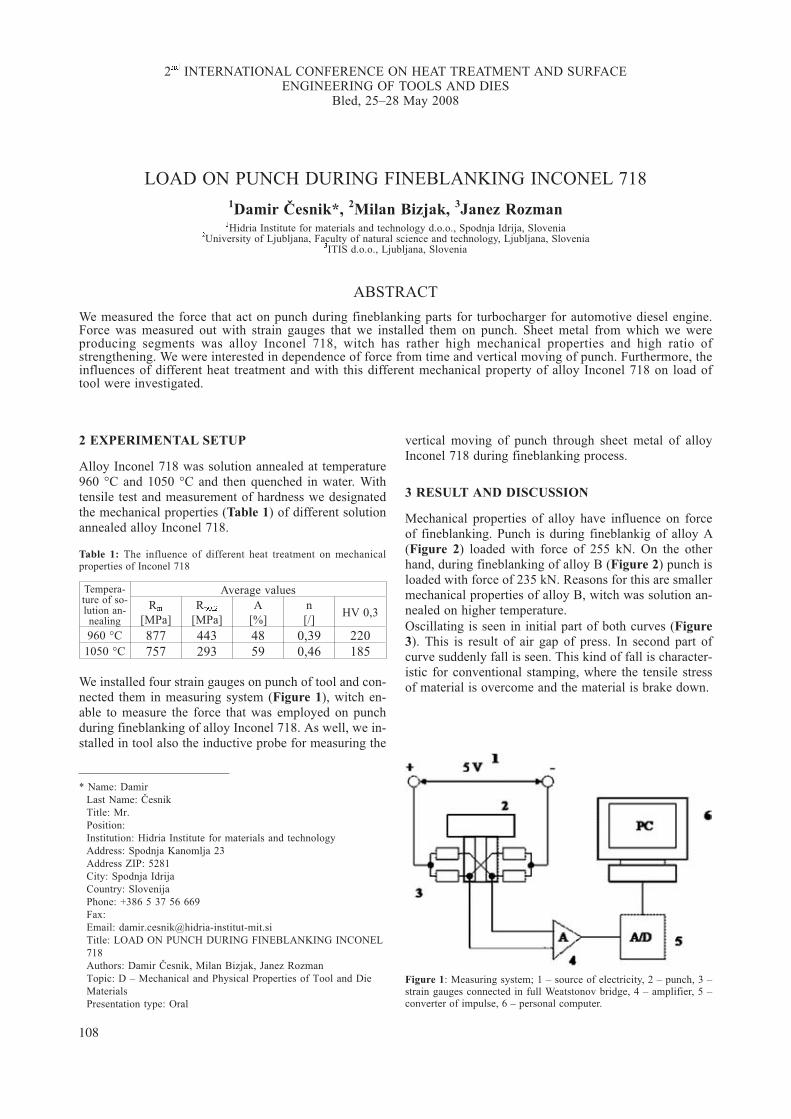
LOAD ON PUNCH DURING FINEBLANKING INCONEL 7181Damir Èesnik*, 2Milan Bizjak, 3Janez Rozman�Hidria Institute for materials and technology d.o.o., Spodnja Idrija, Slovenia
�University of Ljubljana, Faculty of natural science and technology, Ljubljana, Slovenia�ITIS d.o.o., Ljubljana, Slovenia
ABSTRACT
We measured the force that act on punch during fineblanking parts for turbocharger for automotive diesel engine.Force was measured out with strain gauges that we installed them on punch. Sheet metal from which we wereproducing segments was alloy Inconel 718, witch has rather high mechanical properties and high ratio ofstrengthening. We were interested in dependence of force from time and vertical moving of punch. Furthermore, theinfluences of different heat treatment and with this different mechanical property of alloy Inconel 718 on load oftool were investigated.
2 EXPERIMENTAL SETUP
Alloy Inconel 718 was solution annealed at temperature960 °C and 1050 °C and then quenched in water. Withtensile test and measurement of hardness we designatedthe mechanical properties (Table 1) of different solutionannealed alloy Inconel 718.
Table 1: The influence of different heat treatment on mechanicalproperties of Inconel 718
Tempera-ture of so-lution an-nealing
Average valuesR�
[MPa]R����
[MPa]A
[%]n[/]
HV 0,3
960 °C 877 443 48 0,39 2201050 °C 757 293 59 0,46 185
We installed four strain gauges on punch of tool and con-nected them in measuring system (Figure 1), witch en-able to measure the force that was employed on punchduring fineblanking of alloy Inconel 718. As well, we in-stalled in tool also the inductive probe for measuring the
vertical moving of punch through sheet metal of alloyInconel 718 during fineblanking process.
3 RESULT AND DISCUSSION
Mechanical properties of alloy have influence on forceof fineblanking. Punch is during fineblankig of alloy A(Figure 2) loaded with force of 255 kN. On the otherhand, during fineblanking of alloy B (Figure 2) punch isloaded with force of 235 kN. Reasons for this are smallermechanical properties of alloy B, witch was solution an-nealed on higher temperature.Oscillating is seen in initial part of both curves (Figure3). This is result of air gap of press. In second part ofcurve suddenly fall is seen. This kind of fall is character-istic for conventional stamping, where the tensile stressof material is overcome and the material is brake down.
108
2�� INTERNATIONAL CONFERENCE ON HEAT TREATMENT AND SURFACEENGINEERING OF TOOLS AND DIES
Bled, 25–28 May 2008
Figure 1: Measuring system; 1 – source of electricity, 2 – punch, 3 –strain gauges connected in full Weatstonov bridge, 4 – amplifier, 5 –converter of impulse, 6 – personal computer.
* Name: DamirLast Name: ÈesnikTitle: Mr.Position:Institution: Hidria Institute for materials and technologyAddress: Spodnja Kanomlja 23Address ZIP: 5281City: Spodnja IdrijaCountry: SlovenijaPhone: +386 5 37 56 669Fax:Email: [email protected]: LOAD ON PUNCH DURING FINEBLANKING INCONEL718Authors: Damir Èesnik, Milan Bizjak, Janez RozmanTopic: D – Mechanical and Physical Properties of Tool and DieMaterialsPresentation type: Oral

4 CONCLUSION
The load on tool depends upon mechanical properties ofraw material. From view of technology of fineblankingis the most appropriate solution annealed alloy on tem-perature 1050 °C because it has the lowest hardness,yield strength, tensile strength and highest elongation.Lower mechanical properties mean lower load on toolsand more quality cutting surface.During fineblanking process there is no brake down ofraw material. Maximal force and line of force withwhich is loaded punch between fineblankin is importantinformation for choice tool steel and construction of tool.
ICHT & SETD 2008 MECH. AND PHY. PROPERTIES
109
Figure 3: Force as function of vertical moving of punch through sheetmetal; A – solution annealed alloy Inconel 718 at temperature 960°C,B – solution annealed alloy Inconel 718 at temperature 1050°C
Figure 2: Curves for force versus time during process of fineblanking;A – solution annealed alloy Inconel 718 at temperature 960°C, B – so-lution annealed alloy Inconel 718 at temperature 1050°C

THE EFFECT OF SERVICE CONDITIONS ON CRACKINITIATION AND PROPAGATION IN WELDED JOINT OF
HIGH-ALLOY STEEL X201Meri Burziæ*, 2D�enana Gaèo, 3Denijel Burziæ
� Institute GOŠA d.o.o. Belgrade, Serbia� Technical Faculty, University of Bihaæ, Bihaæ, Bosnia and Herzegovina
�Institute for Materials Science, Welding and Forming, Graz University of Technology, Graz, Austria
ABSTRACT
The aim of these investigations was to establish the effect of service conditions (service life, temperature) onbehaviour of base metal and welded joint of high alloy X20, designed for operation at elevated temperatures andaffected by variable loading. The effect of service conditions was analysed by testing the new material and materialthat had been in service for 116,000 hours. Investigations of the new material and base metal that had been inservice as well as of the components of welded joint (weld metal and heat-affected zone) made of high alloy steelincluded determination of the parameters of fatigue-crack growth both at room and at elevated temperature.
The results of these investigations should provide practical contribution toassessment of quality of base metal of thecomponents of welded joint of steel X20, aimed at revitalisation i.e. assessment of strustural integrity and extensionof service life of vital components, high-alloy steel thermal power plants operating at elevated temperatures.
Keywords: high alloy steel X20 CrMoV 12-1, Paris law, crack-propagation rate, fatigue threshold
1 INTRODUCTION
For in-service safety of the components of processingequipment for operation in thermal power plants, themost important characteristics are those describing crackinitiation and growth. This particularly relates to thecracks initiated because of service conditions and effectsof variable loading. Initiation and growth of a crack in-duced by variable loading, i.e. Paris’ law of crack growthestablishing the dependence of crack growth per cycle onacting variable loading i.e. corresponding range of stressintensity factor, is nowadays widely accepted as, basi-cally, it describes the micromechanical behaviour of agrowing crack [1].
For better comprehension of the causes and mechanismsof crack initiation and growth in welded joints of steelsdesigned for operation at elevated temperatures and highpressures, it is obligatory to establish the effect of heter-ogeneity of structure and mechanical properties ofwelded joint on crack initiation and growth, as well as onthe parameters of fatigue-crack growth [2]. Testing of thespecimens with initiated fatigue cracks in base metal,weld metal and heat-affected zone at room temperature,operating temperature of 545°C and max operating tem-perature of 570°C will enable assessment of the effect ofheterogeneity of structure and mechanical properties ofwelded joint on the parameters of fatigue-crack growth,i.e. on the parameters of the Paris equation obtainedfrom the dependence log (da/dN) – log (�K) [3].
2 EXPERIMENTAL SETUP
For the analysis of the effect o temperature and servicelife on mechanical, structural and service properties ofbase metal and welded joint of high-alloy steel X20 de-signed for manufacture of vital components of ther-mal-power plants, two samples were available: sampleN, new pipe-tube �450 x 50 mm approx. 400 mm long,and sample U, welded used pipe-tube with weld metal inthe middle, �450 x 50 mm approx. 500 mm long. Sam-ple U was taken from a steam line for fresh steam in athermal-power plant, having been in service for about116,000 hours. The results of the chemical analysis of
2�� INTERNATIONAL CONFERENCE ON HEAT TREATMENT AND SURFACEENGINEERING OF TOOLS AND DIES
Bled, 25–28 May 2008
110
* Name: MeriLast Name: BurziæTitle: M.Sc.Position:Institution: Institute GOŠA d.o.o.Address: Milana Rakiæa 35Address ZIP: 11000City: BelgradeCountry: SerbiaPhone: +381113809258Fax: +381112410977Email: [email protected]: THE EFFECT OF SERVICE CONDITIONS ON CRACKINITIATION AND PROPAGATION IN WELDED JOINT OFHIGH-ALLOY STEEL X20Authors: Meri Burziæ, D�enana Gaèo, Denijel BurziæTopic: D – Mechanical and Physical Properties of Tool and DieMaterialsPresentation type: Poster

��� ������� � ��� �� ���� � ��� ���� ��� ���� �
����� ��
��� ���� � ������� �� ����� �������� ���� � ����
��������� � ��� ���������� � ������������ ������ �
���� ����� � �������� � ��� � ���� � ����� ���
��� ������ �� ������ ��� ������� � ��� �� ���� �
���� ���� �� ��� � ������� �� �� !��� ������ �����
����� � �������� ���� ������� " �������� ���� �
���� � ���� ����� �#$�! �������� ���� � ���� �
��� ����� �%$� � �������� ���� � ���� � �������
���� &�� �'()��
#��� � ��� ���� ����� ���! ��� �* + , �����-� ���
������ � ( �.����� � ��� ������ ���������� ��
����������� ������ ����! �* + / �������� � ���������
������ ����� ����! �-! �� ��� �������� �������
��� ��� ������ #$ � ��� �� ���� � �.������ ����
����� �� ���� �����������! �������� ����������� �
010 23 � ��. �������� ����������� � 04� 23 ��
���� � ���� � 5�6�
7����������� ���� �� ���� � ��� �������� ����
����� ���� � � �������������� &��� � ��� � ����� 7�
�� ������� ���� ��� ������� � ��� ������ � ����� �����
����! �� ���� �� ������� �� ����� ������������ � ����
���� ���� ���� ������� ���� � ��� ������ � ������
�������� ����! ������������ ������ ���� � ����������
� 8���� �9������
� � � � �� �
��� ��� ��� ��� ����� ���������� � �������� ����������� � �� ���� �� !���������� "��#�� $%%&
�$� �� ���� '(��� ��������)�� ���� � ���������� �� ���)���' *����������� +)���� � �����)�� ,������ ��� ������� -� .% $%%/ �� �01
�/� ��2� � !�3* ' �� ����� 4$% 5��, �$�� "���� (����#6' !�� ��� �7�� 3����� � *�����)�� 8!�3*9 !�3*��2� � ������� �� ����� ��� :�� 5�������� �":$%%;
ICHT & SETD 2008 MECH. AND PHY. PROPERTIES
111
������ �� ������� ������ ���� � � ��� �������� �� ���
��� �� ������� ���������� �� ��� ����� �� ���� �� ���������� ����� ���
��� ����� <
5 "� �� � " 5� � -� ,
"����� = - %�$� %�$& %�>; %�%�& %�%%; ���&% ��%�1 %�;%� %�/�%
"����� = � %�$$ %�/� %�>0 %�%�1 %�%%> ���/; ��%// %�>>� %�/�0

MECHANICAL PROPERTIES OF BORONIZING STEELSAS REPERCUSSION OF BORON PHASES
D. Krumes, I. Kladariæ, I. VitezUniversity of Osijek, Mechanical Engineering Faculty Slavonski Brod, Croatia
ABSTRACT
Results of the boride surface layers investigation, obtained by the torsion and bending methods, point to the betterductility of the mono-phase Fe�B boride layers then the binary-phase FeB + Fe�B boride layers. This is especiallyoutstanding in the case of peaces that are under higher thermal and mechanical load, where the binary-phase layerbecause of higher local stresses has higher tendency to fall of, respectively to shell.
Keywords: boronizing, boron phases, boride layers, mechanical properties
1 INTRODUCTION
Boronizing is a thermochemical process in which thechemical element boron diffuses in the surface layer ofsteel substrates. In the surface layer of steel substrate,boron forms with the iron Fe�B, as desirable compound,and FeB as undesirable compound. Boride layers haveextraordinary high hardness. FeB is a little bit harder(1800–2100 HV0,1) than Fe�B (1400–1600 HV0,1), butmuch brittle, so its forming have to avoid in the practice.During boronizing of the forging matrixes, drawing toolsand shaping tools it is needed, among other, to determinethe toughness of the boronized material [1 to 3].The aim of the conducted investigation was to determinethe ductility of the boron phases using methods in whichthe influence of the core on the boride layers will beelower (lower result scatterings). For the ductility deter-mination of the boride layers two independent methodswere chosen: by the torsion method and by the bendingmethod.
2 INVESTIGATION
Torsion method used was detection of the cracks appear-ance of the boride layer during torsion cylindrical speci-men. Specimens were made from C 15 and 20 CrMo 5,designated in accordance with data in Table 1, andboronized with the appropriate regimes and in the condi-tions which in one way led to forming of the binaryphase FeB + Fe�B boride layer, and in the other way toforming mono phase boride layer Fe�B.Boronizing was performed in solid mediums. Firstboronizing regime and conditions, which resulted inmono phase boride layer Fe�B formation, include: boro-nizing agent with low activity (SiC, B�C, KBF�) usinglower boronizing temperature T = 850 °C andboronizing time t = 4 hours. Second borinizing regimeand conditions, in which the binary phase boride layer
FeB + Fe�B is formed, include boronizing agent with in-creased activity (Na�B�O�, B�C, KBF�) using higherboronizing temperature T = 950 °C and lowerboronizing time t = 2 hours. Besides classical metallo-graphic technique (Figure 1 and Figure 2), the exami-nation of the formed boride layers were performed bythe scanning electron microscopy – microsonde. For theboride layer type determination, surface layer of thespecimens were also examined by the X-ray diffraction
2�� INTERNATIONAL CONFERENCE ON HEAT TREATMENT AND SURFACEENGINEERING OF TOOLS AND DIES
Bled, 25–28 May 2008
112
20 CrMo 5 100xFigure 1: Boride layer photomicrograph
Table 1: Specimen identification numbers
Steel C 15 Steel 20 CrMo 5Boron phases Boron phases
FeB+Fe�B Fe�B FeB+Fe�B Fe�BSpecimen identification Nr. Specimen identification Nr.
0,1 1,1 2,1 3,10,2 1,2 2,2 3,20,3 1,3 2,3 3,30,4 1,4 2,4 3,40,5 1,5 2,5 3,50,6 1,6 2,6 3,6

method. Surface layer, formed on the specimen, hasstructure and parameters of FeB and Fe�B boride com-pounds, so as some of Fe� (B, C) and Fe�� (B, C)� car-bide type compounds. Ductility examination by torsionmethod was done with testing machine and additionalequipment.From results of the ductility examination by torsionmethod can bee concluded that the torsion angle of bothspecimen, one made from carbon steel C 15 and the
other from alloyed steel 20 CrMo 5, in case of monophase boride layer Fe�B is higher than in case of binaryphase boride layer FeB+Fe�B. It can be seen from themean value of torsion angle x�=22,67° and y�=29,17° forbinary phase boride layers, so as x�=32,67° and y�=34,5°for mono phase boride layers. Bending method used forductility determination is bending deformation of the tinflat specimen (0,85x10x100 mm), previously boronisedin suitable mediums, described before.The results boride layers ductility examination by thebending are given in Figure 3.
3 CONCLUSIONS
Values obtained by measuring the deflection x� and x
(Figure 3) show that method of boride phase ductility de-termination by bending (so as previous method) givesbetter results in the case group of specimen (x�) withmono phase boride layer Fe�B comparing to the group ofspecimen (x) with binary phase boride layer Fe�B+FeB.The most probable cause of better mechanical properties,ductility as wearing resistance, mono phase comparing tobinary phase boride layers (even though the hardness ishigher by binary phase FeB+Fe�B boride layers) is dif-ferent thermal expansion coefficients. During workpieces (specimens) treatment cooling forms compressionstresses are in the Fe�B layer and tension stresses in FeBlayer. The stresses with different sign can produce microcracks in boride phase vertical to the layers as betweentwo layers.
4 REFERENCES
[1] J. Burke, The Kinetics of Phase Transformations inMetals, Oxford, 1980
[2] I. Esih, D. Krumes, S. Araèiæ, Effect of Boronising onErosion of Carbon and Low Alloy Steels in NaCl/SiO�
Water Suspensions, 14�� Int. Corrosion Congress, CapeTown, South Africa, 1999, 4, 301-309
[3] D. Krumes, I. Vitez, Duktilitätmessung der Boriedphasenauf Stählen, 7�� Int. DAAAM Symposium, Vienna, Aus-tria, 1996, 231-233
ICHT & SETD 2008 MECH. AND PHY. PROPERTIES
113
20 CrMo 5 500xFigure 2: Boride layer photomicrograph
Figure 3: Results boride layers ductility examination by bending

EFFECT OF HEAT TREATMENT ON THE MECHANICALPROPERTIES OF TOOL STEELS
Reinhold Ebner, Stefan Marsoner, Werner Ecker, Mario LeindlMaterials Center Leoben Forschung GmbH, Leoben, Austria
1 LOADING, DAMAGE AND LIFETIME OFTOOLS
In service tools and tool materials are normally subjectedto (1) mechanical loads, including thermo-mechanicalloads, (2) tribological loads, and (3) thermal loads.Mechanical/thermo-mechanical loads cause cyclicstresses and strains which lead to fatigue type damage ef-fects. If the stresses are high enough cyclic plastic strainsoccur in addition to the cyclic elastic strains. Tribolo-gical loading takes place at the tool surface and causesstresses, strains and often also chemical interactionwhich lead to damage at and near the surface. Thermalloads may lead to microstructural changes, e.g. precipita-tion of dissolved alloying elements, phase transformation(e.g. retained austenite to martensite) or coarsening ofprecipitates.Damage mainly takes place in the highest loaded regionsof a tool. The damage process is strongly depending onthe stresses and strains induced by the manufacturingprocess for which the tool is used on the one hand and onthe microstructure and the mechanical properties of thetool material which depends on the tool steel grade andon the heat treatment on the other.Tool steels are multiphase materials which are consistingof a metallic matrix with embedded hard phases, mainlycarbides, nitrides or carbonitrides. Due to the highstrength level of tool steels even small plastic strainslead to the formation of micro-cracks, e.g. by cracking of
carbides or carbide/matrix interfaces. The performanceof tools is strongly related to the behaviour of these mi-cro-cracks. It should be pointed out in this regard thatmicro-crack tip loading does not only result from thestress range caused by the manufacturing process forwhich the tool is used but also from the above mentionedresidual stresses. The initial size and the crack tip load-ing conditions determine whether these micro-cracks areable to grow or in other words whether the damage pro-cess stops or proceeds after the micro-crack formation.There is no consistent definition available for the end oftool life. The failure criterion varies strongly with the ap-plication and the type of tools. In some cases tools haveto be replaced if the first small cracks appear which areimprinted on the workpiece, whereas in other cases thetotal tool failure is relevant. But as a general rule reach-ing a critical crack size, which is characteristic for a spe-cific application, can be taken as a feasible lifetime crite-rion.
2 MATERIAL RESPONSE TO THEMECHANICAL LOADING AND DEFINITION OFRELEVANT MATERIAL PROPERTIES
Determination of tool loads in terms of stress, strain andtemperature cycles is a highly challenging task. It re-quires a coupling of the simulation of the manufacturingprocess for which the tool is applied with the finite ele-ment calculation of the stresses, strains and temperaturesin the tool.Most tools exhibit some highly stressed areas in whichcyclic plastic deformation occurs very localised. Due tothe high hardness these plastic strains occurring in toolsare normally small. If cyclic straining is not fully revers-ible, which is often the case, this is leading to the devel-opment of residual strains. These residual strains lead tothe formation of residual stresses. Due to the highstrength level of tool steels even low residual strains maylead to high residual stresses. These residual stresses aresuperposed to the stresses induced by the manufacturingprocess for which the tool is applied. The residualstresses result in a change of the stress ratio which isknown to have a significant effect on the growth behav-iour of the micro-cracks and the whole damage process.
2�� INTERNATIONAL CONFERENCE ON HEAT TREATMENT AND SURFACEENGINEERING OF TOOLS AND DIES
Bled, 25–28 May 2008
114
* Name: ReinholdLast Name: EBNERTitle: Prof.Dr.Position: Associate ProfessorInstitution: Materials Center Leoben Forschung GmbHAddress: Roseggerstrasse 12Address ZIP: 8700City: LeobenCountry: AustriaPhone: + 43-3842-45922Fax: + 43-3842-45922-5Email: [email protected]: Effect of heat treatment on the mechanical properties of toolsteelsAuthors: Reinhold EBNER, Stefan MARSONER, Werner ECKER,Mario LEINDLTopic: D – Mechanical and Physical Properties of Tool and DieMaterialsPresentation type: keynote lecture

A detailed analysis of the behaviour of tools in servicerequires finite element calculations that are taking thestatic and the cyclic elastic-plastic material behaviourinto account. Such advanced finite element simulationsrequire powerful material models which allow a realisticprediction of the material response under the very spe-cific loading conditions occurring in tools. The materialmodels must be able to describe among others the staticstress-strain curve, isotropic and kinematic hardening,elastic and plastic shakedown, ratchetting, visco-plasticbehaviour, or stress relaxation.Complex test procedures and time consuming and ex-pensive material modelling procedures are necessary toderive suitable material models (constitutive equations).A significant drawback is that material models availabletoday are mostly based on phenomenological principles.Most of the parameters in these models can be hardly in-terpreted on the basis of well defined physical meanings.Due to the high effort necessary for the determination ofparameters for the constitutive equations and the missingphysical interpretation only very limited information isavailable in literature. Most activities in this respect wereperformed on the more ductile hot work tool steels, forhigh speed steels which have lower ductility only a fewactivities are known to the authors of this paper.For a prediction of tool lifetimes also the effect of cyclicstresses and strains on the damage process and on thelifetime is required. The fatigue lifetime behaviour is of-ten described by means of the double-log strain ampli-tude versus cycles to failure curve which allows a de-scription of the low cycle fatigue behaviour, the highcycle fatigue behaviour and the "fatigue strength" in onediagram. Most literature on the fatigue properties is fo-cussing on the high cycle fatigue regime and the fatiguestrength. It is well known that the lifetime in the high cy-cle fatigue regime is controlled by defects. This meansthat micro-crack forming microstructural elements, e.g.non metallic inclusions, or machining induced micro-de-fects control the fatigue behaviour whereas the hardnesshas only a minor or even no effect. In most tool applica-tions the tool materials are subjected to fatigue loadingunder high compressive mean stress. Unfortunately, al-most no literature is available on the fatigue behaviour oftool materials under such conditions.Assuming that linear damage accumulation is applicable(Miner rule) the double-log strain amplitude versus cy-cles to failure curve can be also taken as basis to calcu-late the damage increment produced by one single loadcycle. This can be used further to calculate the number
of cycles necessary to produce a crack with a criticallength. Again, there is also very little information avail-able in literature regarding the effect of loading on thefatigue life of tool steels. This is especially true for theeffect of heat treatment.In practice the service properties of tool steels are stillcharacterised mainly by their hardness. Material data de-termined in uniaxial tension tests are standard only incase of the more soft and ductile materials, e.g. hot worktool steels. For the very hard tool steel grades with lowductility, e.g. high speed steels, it is even hard to get reli-able static material data from tension and compressiontests. Also cyclic material data are very rare; this is alsotrue for the effect of heat treatment.Goal of this paper is to give some basic information onthe mechanical properties which are relevant for the toolperformance and to point out the effect of heat treatmenton these properties.
3 EFFECT OF TOOL STEEL GRADE AND HEATTREATMENT ON THE LIFETIME RELEVANTMATERIAL PROPERTIES
The properties of tool steels are controlled by the toolsteel grade on the one hand and on the heat treatment onthe other. The steel grade determines the strength andductility potential of the tool steel and the heat treatmentdetermines to which extent this potential is used.The heat treatment of tool steels consists of several steps,the most relevant steps and the controlling factors are:(1) Austenitizing (temperature, time), (2) Quenching(cooling rate), and (3) Tempering (tempering tempera-ture, cooling temperature, number of tempering cycles).In the present paper the effect of heat treatment(austenitizing temperature, quenching rate, temperingtemperature) will be demonstrated for various steelgrades with focus on tool steels with medium and highervolume fractions of carbides. The investigations concen-trate on the static mechanical properties (characteristicstrength and ductility values, stress-strain behaviour,fracture toughness) and cyclic mechanical properties (cy-clic stress-strain behaviour, strain amplitude versus cy-cles to failure curve, fatigue crack growth behaviour).Furthermore the application of these data for advancedfinite element calculations of the evolution of loadingconditions (evolution of stresses and strains including re-sidual stresses) and the damage of tools will be demon-strated.
ICHT & SETD 2008 MECH. AND PHY. PROPERTIES
115

DETERMINATION OF LOWER BOUND OF FRACTURETOUGHNESS OF SUSPENSION SPRING MATERIAL
Nenad Gubeljak1*, Jo�ef Predan1, Bojan Senèiè2, Jelena Vojvodiè Tuma3,Monika Jenko3
�University of Maribor, Faculty of Mechanical Engineering, Smetanova 17, SI-2000 Maribor, Slovenia�Štore Steel d.o.o., �elezarska c. 3, SI-3220 Štore, Slovenia
�Institute of Metals and Technology, Lepi pot 11, SI-1000 Ljubljana, Slovenia
ABSTRACT
Modern suspension springs of vehicles are made from one single spring, which should carry all loads. It is wellknown that spring materials have quite low fracture toughness. It makes that spring are very sensitive on presents ofinclusions. Mechanical properties and fracture toughness are determined on specimens cut out tested spring sample,as is shown in Figure 1. The mechanical properties are determined on mini tensile specimens (MTS).
The fracture toughness testing was performed on specimens cut from tested springs. The tested fracture toughnessspecimens exhibited brittle behaviour (as is shown in Figure 2) and condition for fracture toughness parameter K��
are completed.
Critical sizes of inside fatigue crack around inclusions are determined by using SINTAP procedure. It is assumedthat the circular fatigue crack appeared around inclusions (e.g. Al�O�) (Figure 3).
The aim of our paper is find lower bound of fracture toughness in order to accept regular size of inclusion close thesurface of bended spring. Theoretical fracture toughness values had been calculated for fixed inclusion size andconstant mechanical properties.
2�� INTERNATIONAL CONFERENCE ON HEAT TREATMENT AND SURFACEENGINEERING OF TOOLS AND DIES
Bled, 25–28 May 2008
116
Figure 3: Result of spring integrity analysis by using SINTAP proce-dure for inclusion
Figure 1: Orientation and position of specimens for determinationmechanical properties and fracture toughness
Figure 2: Fracture behaviour of single edge bend specimen
* Name: NenadLast Name: GubeljakTitle: Prof.Dr.Position: lecturer, ProfessorInstitution: University of Maribor, Faculty of Mech.Eng.Address: Smetanova 17Address ZIP: SI-2000City: MariborCountry: SloveniaPhone: +386-2-220-7661Fax: +386-2-220-7990Email: [email protected]: Determination of lower bound of fracture toughness ofsuspension spring materialAuthors: Gubeljak N., Predan J., Senèiè B., Tuma J., Jenko M.Topic: D – Mechanical and Physical Properties of Tool and DieMaterialsPresentation type: Oral

ADVANCED TOOLMATERIALS


ADVANCE TOOL MATERIALS
FATIGUE RESISTANT PM TOOL STEELS
Ziya Devrim Caliskanoglu*, Jochen Perko, Hubert Lenger
Traditional, conventionally manufactured cold work toolsteels e.g. DIN 1.2379 (X155CrVMo12-1), are often in-capable of withstanding the high loads in high-perfor-mance cold work applications. The reason for early fail-ure of the material obviously depends heavily on theload profile of the particular application. Typically oc-curring failure mechanisms are abrasive wear, adhesivewear, cyclical plastic deformation, the formation of fa-tigue cracks and spalling of flat surfaces and/or edges.To increase the abrasive wear resistance of tool steels,the matrix strength must be increased and a certain per-centage of hard carbides must be present. To increase theadhesive wear resistance, the average distance betweencarbides in the high-strength matrix of the tool steelshould be minimised. To avoid plastic deformation andspalling at the edges due to cyclical loading, the toolingmaterial must possess both a high-strength matrix andhigh ductility.The failure mechanisms described can occur either aloneor in combination. For this reason, high-performancepowder metallurgical tool steels with a chemical analy-sis, high homogeneity, high cleanliness, homogenouscarbide size and distribution, and high reproducibility ofthose properties optimised for the particular loading situ-ation, should be used for highly stressed tooling. In thispresentation, we demonstrate how the material propertiescan be influenced by the manufacturing process and thechemical analysis, using selected high-performancesteels as examples.Powder metallurgy tool steels and high speed steels usedfor highly stressed tooling must have a high toughness aswell as a high strength and high wear resistance, andmust above all posses the best possible fatigue propertiesin order to ensure a suitable resistance to fracture. To in-crease the working life of tooling it is therefore neces-
sary to drastically reduce the number of fracture-initiat-ing defects such as non-metallic inclusions and carbideclusters. The negative influence of primary carbide clus-ters or those formed eutectically from the melt in highlyalloyed, conventionally manufactured steels can belargely prevented using a powder metallurgy manufac-turing route. Non-metallic inclusions remain as the limit-ing defects reducing the working life of tooling. Themain sources of this type of inclusion are the furnaceslag and the top slag in the tundish.For this reason, the traditional PM process was modifiedduring construction of the Böhler-Uddeholm PM plant inKapfenberg. The installation of an electro-slag heatingunit which heats the top slag in the tundish, in combina-tion with an electromagnetic stirrer, protects the meltfrom oxidation. In addition this means that inclusionscaused by the furnace slag can be precipitated out bystirring, and a constant melt temperature and cleanlinesslevel can be maintained.It is known that in the area of low-cycle-fatigue, at highstrain amplitudes and a low number of cycles, the resis-tance to fatigue fracture can be improved by increasingthe ductility of an alloy. In the area of high-cycle-fatigue,at low strain amplitudes but a high number of cycles, animprovement in the resistance to fatigue fracture can inprinciple be achieved by increasing the strength. The lin-ear correlation between strength and high-cycle-fatiguestrength is however only valid to a strength R ofapprox. 1000MPa. High-strength tool steels have a sig-nificantly higher strength than this, at which level the fa-tigue strength is no longer a function of the strength butof the defect size in the material. In powder metallurgymaterials, defects are primarily caused by non-metallicinclusions, but also by oversized primary carbides andcarbide clusters.These theoretical principles were put into practice in thedevelopment of new microclean� grades. Due to theirversatility, M4-type steels manufactured using the pow-der metallurgy route are used often. In many cases how-ever a more exact matching of the properties of the toolmaterial to the stress/loading profile of the application isnecessary to optimise the tool life. For this reason,Böhler Edelstahl developed the highly ductile, low-car-bide steel K890 microclean�, and the high-strength, car-bide-rich steels S390 microclean� und S290 microclean�
from the PM-M4 material. This enabled the properties ofthe materials to be optimally adapted to fit thestress/loading profile of the application.In will be shown how the highly ductile materialK890 microclean� was developed from the standard
2�� INTERNATIONAL CONFERENCE ON HEAT TREATMENT AND SURFACEENGINEERING OF TOOLS AND DIES
Bled, 25–28 May 2008
119
* Name: DevrimLast Name: CaliskanogluTitle: Dr.Position: R&DInstitution: Böhler Edelstahl GmbH & Co. KGAddress: Mariazellerstr. 25Address ZIP: 8605City: KapfenbergCountry: AustriaPhone: +43 3862 20 37194Fax:Email: [email protected]: Fatigue resistant PM tool steelsAuthors: Devrim Caliskanoglu, Jochen Perko, Hubert LengerTopic: E – Advanced Tool MaterialsPresentation type: Oral

PM-M4 steel type with a reduced primary carbide con-tent and a high-strength matrix in order to achieve ahigher resistance to fracture in applications with higherbending stresses. It will be demonstrated how an in-crease in the primary carbide content and the matrixstrength compared to PM-M4 types resulted in the highercompressive strength and wear resistance of the steels
S390 microclean� und S290 microclean�. Thanks to itsuniversal property profile, S390 microclean� has estab-lished itself on the market as a problem solver which canbe used in a wide variety of applications. In contrast, thehighly-alloyed S290 microclean� can be seen as atougher alternative to cemented carbides.
ADVANCE TOOL MATERIALS ICHT & SETD 2008
120

ADVANCE TOOL MATERIALS
DEVELOPMENT OF A HYBRID TOOL STEELPRODUCED BY SPARK PLASMA SINTERING
Massimo Pellizzari*, M. Zadra, A. FedrizziDepartment of Materials Engineering and Industrial Technologies, University of Trento, Via Mesiano 77, 38050 Trento – Italy
ABSTRACT
The in-service performance of a tool can be correlated tothe material properties and its production process. In thecase of tool steels, involving high-speed and hot worktool steels, both factors contribute in determining themicrostructure, on which properties as hardness, tough-ness, strength, wear and thermal fatigue resistance aredependent.The microstructure of tool steels is constituted by ahardenable metallic matrix strengthened by a dispersionof hard particles, usually carbides. "Primary" carbidesprecipitate during solidification and have quite largesize. With a given alloy chemistry, their phase composi-tion, size, shape and distribution are determined by thecourse of solidification, in conjunction with the processof hot working the ingot to a mill shape. "Secondary"carbides precipitate in solid phase during solidificationand even during following quenching-tempering heattreatment. In the case of hot work tool steels just second-ary carbides are present.The tool performance is determined by the primary car-bide population and by the degree of secondary harden-ing of the metallic matrix. The distribution of the blockycarbides also has a decisive influence on the toughnessof the tools, because large carbide clusters nucleate themicrocracks which eventually cause rupture. I order toproduce high speed steels with higher toughness thePowder Metallurgy process was introduced. This tech-nology allows a finer and more homogeneous distribu-
tion of primary carbides, obtained during the atomizationprocess of the elementary powder. PM steels shows con-siderable higher toughness/hardness ratio than the corre-sponding forged alloys. Their toughness, however, re-mains largely lower that that of hot work tool steels,which still represent the best product in all such applica-tion where a high toughness is required.Hans Berns, professor at the University of Bochum (Ger-many), as first proposed a "hybrid" steel, obtained bymixing proper quantities of a coarse spherical high speedsteel powder II, containing a high percentage of dis-persed carbides, with a fine hot work tool steel powder I,of a low carbide content. After hot isostatic pressing(HIP) wear resistant areas II were dispersed in a tougherarea I. After hardening and tempering, a double disper-sion with 60%II-40%I showed 50% increase in fracturetoughness over a reference PM high speed steel of com-parable wear resistance and bending strength.The aim of this work is the production of a steel havingsimilar features, by means of a different sintering tech-nique, namely the Spark Plasma Sintering (SPS). Thismethod provides the consolidation-sintering aided by acurrent flow. The heating by Joule effect with pulsedcontinuous current allows very high heating rates of thegraphite die (up to several hundreds degrees Centigradeper minute) where the powder to be sintered is placed.The magnetic fields and the micro plasma produced bythe peculiar current wave forms enhance sintering,through the surface activation of the powder particlesand favouring diffusion processes. The laboratory ofmetallurgy at Trento University in 2005 acquired one ofthe two SPS units in Italy. This technology offers veryinteresting advantages:1. over consolidation techniques like hot isostatic press-
ing HIP it allows the direct production of the tool,thus avoiding the fabrication of a semi-finished prod-uct;
2. it allows to obtain full density components by usinglower times and temperatures than those employed inHIP. In this way this techniques is an excellent candi-date for sintering of nanostructured and/or nanosizedpowders, allowing to limit grain growth;
3. it allows to work under controlled atmosphere and inhigh vacuum;
2�� INTERNATIONAL CONFERENCE ON HEAT TREATMENT AND SURFACEENGINEERING OF TOOLS AND DIES
Bled, 25–28 May 2008
121
* Name: MassimoLast Name: PellizzariTitle: Prof.Dr.Position: Associate professorInstitution: Dpt. Materials Engineering and IndustrialTechnologies, University of TrentoAddress: Via Mesiano 77Address ZIP: 38050City: TrentoCountry: ItalyPhone: +39 0461 882449Fax: +39 0461 881977Email: [email protected]: Development of a hybrid tool steel produced by SparkPlasma SinteringAuthors: M. Pellizzari, M. Zadra, A. FedrizziTopic: E – Advanced Tool MaterialsPresentation type: Oral

4. it permits to establish temperature gradients in thedie, thus allowing the realization of multilayered orFunctionally Graded Materials.
5. It allows to sinter mixed powders and to obtain "com-posite microstructures" like those to be producedwithin this project.
Two commercial available powders (Ospray) were se-lected for this work, namely an AISI H13 hot work toolsteel and a AISI M2 high speed steel, having particlemean size lower than 20 microns. X-ray diffraction andmetallographic analysis allowed to determine the powderconstitution given by ferrite, austenite and carbides.Samples in forms of 30mm diameter discs, 4-5mmheight were produced by Spark Plasma Sintering undervacuum conditions. Optimum sintering conditions wereindividuated by varying both, sintering temperature andtime: near-full density samples, preserving quite smallgrain size could be obtained at 1100°C for 5 minutes at apressure of 60MPa. Starting from the base AISI H13powder four different blends were obtained by adding20, 40, 60, 80%wt AISI %M2. Samples where then vac-uum heat treated by austenitizing at 1050°C x 30min anddouble tempering at 625°C x 2hours each. The basesteels reached a final hardness of 430HV10 (~44HRC,AISI H13) and 493HV10 (~49HRC, AISI M2), respec-tively. The hardness of the blends increased linearly withincreasing amount of AISI M2 powder.An apparent fracture toughness Ka was determined usinga procedure just proposed to overcome the difficulties inintroducing fatigue precrack to small fracture toughnessspecimens. Notches depth with root radii of 50µm wereelectro discharge machined in 6x3x25.2mm� specimens.The ratio of notch depth to the specimen width (a/w) wasset at 0.5. The decrease in stress triaxiality with increas-ing � causes a decrease in the stress that would initiatefracture, so that the Ka value is higher than that of K��
measured on precracked sample. The present valueshighlight a good toughness level for AISI M2(45MPam-1/2) whilst a comparatively low value couldbe observed for AISI H13 (50MPaxm-1/2). Values of
45MPa and 80MPa could be expected for the two steelson the base of experimental data obtained by the authorsin the past. The toughness drops by increasing%AISIM2, i.e., by increasing hardness, even if not con-tinuously. Low and highly dispersed values of Ka wereobserved by 60-40% and 40-60% blends. Fractographicanalysis on AISI H13 allowed to detect a general ductilefracture accompanied by a strong intergranular compo-nent. The fracture path easily follows the particle bound-ary in correspondence of which a lot of roundmicropores were revealed by scanning electron micros-copy (SEM). Micropores were also detected at the inter-face between AISIH13 particles and high speed steel.Accordingly, blends containing large fractions of AISIH13 behave worse than those containing high fractionsof AISI M2. The large scatter for the blends having inter-mediate composition can be interpreted on the base oftheir intermediate fracture behaviour, influenced by al-most interconnected fracture path of AISI H13. Thepresent results suggest that sintering conditions can befurther optimized for AISI H13.Dry sliding tests were carried out using a block on discconfiguration. A counterpart disc (40mm external diame-ter, 10mm width) of ASP2052 salt bath quenched andtempered to 70HRC was selected. The sliding speed was0.55 m/sec and a load of 180N was applied for a totalsliding distance of 3000m. The wear volume was deter-mined by a stylus profilometer, after measuring the worntrack profile in three different positions. The wear mech-anism was given mainly by abrasion, as evidenced by thebig scratches on the rubbing surface after the test. Tracesof oxidation were also observed. According to the hard-ness increase, the wear resistance of the hybrid steels in-creased linearly with increasing %AISI M2.Microstructural analysis of the worn cross sections re-vealed a strengthening mechanism after which the plasticdeformation of the relative soft AISI H13 regions iscounteracted by the hard AISI M2 particles. Hence, thethickness of the plastically deformed layer linearly de-creased with increasing amount of AISI M2.
ADVANCE TOOL MATERIALS ICHT & SETD 2008
122

ADVANCE TOOL MATERIALS
STRESS STATE OF 12% Ni MARAGING STEEL AFTER AMODIFIED PROCEDURE OF PRECIPITATION
HARDENING
Janez Grum*, M. ZupanèièFaculty of Mechanical Engineering, University of Ljubljana, Slovenia
ABSTRACT
Compressive residual stresses in a surface layer can essentially improve fatigue resistance of the surface layer of amaterial of which exacting thermo-mechanically and dynamically loaded machine components and tools are made.In order to establish such a stressed state, a combination of cold deformation and heat treatment of maraging steel,which is suitable for tool manufacture, was applied. Mechanical hardening of the surface consists in shock peening,i.e. roto peening. Local plastic deformations of the surface layer of maraging steel in the soft state produce a higherdensity of dislocations and increase compressive residual stresses.
The combined application of cold deformation and precipitation annealing to specimens results in the formation ofvery fine precipitated phases. The microstructure obtained improves mechanical properties of the materialconcerned and provides the required variations of compressive residual stresses.
Keywords: maraging steel, residual stresses, roto-peening, precipitation hardening
1 INTRODUCTION
Tools for die casting of non-ferrous alloys consist ofcomponents subjected to strong dynamic andthermo-mechanical loads. The most critical tool compo-nents are elements of mould cavity, where different dam-ages such as wear, micro cracks, and other imperfectionswill occur.Maraging steels intended for tool production exhibit nu-merous technological advantages over common toolsteels. Hardening of maraging steel consists in phaseprecipitation in a matrix of comparatively soft saturatednickel martensite. The process is relatively slow and re-lated to the mechanism of diffusion, which proceeds uni-formly through the tool-component cross-section. Conse-quently, the final properties of maraging steel arehomogeneous across the entire tool cross-section. After
precipitation hardening, relatively low compressive re-sidual stresses will be present. This is the reason forlooking for possibilities to improve residual stress varia-tion in the thin surface layer. In the course of precipita-tion hardening of maraging steel, phases will precipitatein the matrix. They interfere with gliding of dislocationsacross a glide plane and thus essentially change mechan-ical properties of the material. A change of hardness inthe initial phases of precipitation was described with anexponential equation by Squired in Wilson [1]. Hard-ness, indeed, has a strong influence on wear resistance ofa material, particularly with die casting tools. Grum andZupanèiè [2] found that after precipitation annealing at atemperature of 450 °C for two hours, operating hardnessof a tool of around 44 HRC, tensile strength R of 1250MPa and impact toughness KU of 16 J was achieved. Itis proposed by the authors to apply the combination ofcold deformation and precipitation annealing to improvethe properties [3].
2 EXPERIMENTAL PROCEDURE
Specimen preparation: The initial state of maragingsteel was a forged bar of 80 mm in diameter, from whichflat specimens were cut in the transverse direction. Thespecimen preparation was followed by the first set ofmeasurements of residual stresses.The second set of measurements of residual stresses wasperformed after cold deformation of the surface byroto-peening using different parameter combinations,which provided different treatment intensity. The treat-ment intensity is determined by a kinetic energy of solid
2�� INTERNATIONAL CONFERENCE ON HEAT TREATMENT AND SURFACEENGINEERING OF TOOLS AND DIES
Bled, 25–28 May 2008
123
* Name: JanezLast Name: GrumTitle: Prof.Dr.Position: ProfessorInstitution: Faculty of Mechanical EngineeringAddress: Aškerèeva 6Address ZIP: 1000City: LjubljanaCountry: SloveniaPhone: +386 1 4771 203Fax:Email: [email protected]: STRESS STATE OF 12% Ni MARAGING STEEL AFTERA MODIFIED PROCEDURE OF PRECIPITATIONHARDENINGAuthors: J. Grum, M. ZupancicTopic: E – Advanced Tool MaterialsPresentation type: Oral

particles impacting the specimen surface. It is given bythe number of flap rotations (n = 2000, 2500, and 3000min��).The third set of measurements of residual stresses wasperformed after cold deformation of the specimens,which were additionally hardened by precipitation an-nealing. In the course of precipitation annealing veryfine phases precipitated. They hardened the material andprovided its final mechanical properties.Residual stresses in the surface layer: Thethrough-depth residual-stress profiles of the specimenswere determined using the relaxation hole-drillingmethod. The method consists in measurement of defor-mations occurring in the hole vicinity. From the latter,equivalent homogeneous or incremental residual stressesare calculated. Figure 1 shows three residual-stress pro-files, i.e. the initial state, state after cold-deformation ofthe surface, and the state after subsequent additional pre-cipitation annealing.The »initial state« curve represents a profile of maxi-mum residual stresses in the maraging steel specimensafter having been cut from the bar. The profiles mea-sured are located predominantly in the tensile zone andrange between 100 and 200 MPa. Such an unfavourablestress state is a consequence of specimen cutting andsubsequent flat grinding, which produces mainly tensileresidual stresses in the surface layer. The stress statemeasured was a starting point for specimen comparisonafter hardening by cold deformation (the second set ofmeasurements) and after hardening by combined harden-ing (the third set of measurements) respectively.The residual-stress profiles after roto peening will shiftto the compressive zone, which is represented by the»Roto 2500« curve. From the viewpoint of the stressvariation the change indicates essential improvement ofwear resistance of the material. The compressive stresszone is present through depth z of 1.0 mm, and attainsthe highest value, i.e. 1100 MPa, in a depth of 0.12 mm.Cold deformation by roto peening was followed by addi-tional precipitation annealing at a temperature of 450 °Cfor 2 hours. Subsequently, the highest compressivestress, i.e. 550 MPa, was obtained in a depth of 0.25 mm.A comparison with the state prior to precipitation anneal-ing showed the following differences:
– The residual stresses in the surface layer were essen-tially reduced. This was to be expected since thiswas a result of both the relaxation stresses at ele-vated temperatures and diffusion processes generat-ing new phases with a changed crystal lattice.
– The difference between the minimum and maximumstresses will get smaller after precipitation, which isa result of the processes in precipitation annealing.
– After precipitation annealing the residual-stress pro-files show a considerably lower value of the com-pressive stresses (550 MPa) with increased specimenhardness (44 HRC).
3 CONCLUSIONS
The investigation conducted on the combined hardeningof maraging steel showed that treatment of maragingsteel with preliminary mechanical surface hardening wasefficient. Mechanical hardening introduces considerablecompressive residual stresses in the surface layer. Thelatter interfere with the initiation and propagation of mi-cro cracks and, in certain cases, essentially improve re-sistance of tools or machine components tothermo-mechancial fatigue.The chosen maraging steel with 12% of nickel, which issuitable for the production of thermo-mechanicallyloaded tools, was treated by roto peening using three dif-ferent parameter combinations. The flap rotation speedsof roto-peening flap n were equal to 2000, 2500, and3000 min��. After treatment the measurements performedshowed high values of the compressive residual stresses.After additional precipitation annealing of a specimen,hardness increases whereas the residual-stress variationswill be reduced. The residual stresses persist to be of thecompressive character, which ensures good wear resis-tance and fatigue resistance of the material.
4 REFERENCES
[1] Wilson R.K.: Maraging Steels – The First 30 Years,Maraging steels – recent developments and applications,Metals & Minerals Society, Warrendale, Pennsylvania,1988
[2] Grum J., Zupanèiè M.: Suitability assessment of replace-ment of conventional hot-working steels with maraging
ADVANCE TOOL MATERIALS ICHT & SETD 2008
124
Figure 1: Residual-stress profiles of maraging steel after cold deformation of surface layer and after subsequent precipitation hardening at 450°Cfor2 hours.

steel. Part 1, Mechanical Properties of Maraging Steel af-ter Precipitation Hardening Treatment, Z. Met.kd., 2002,Bd. 93, Hf. 2, 164-171
[3] Grum J., Zupanèiè M., Kikelj R.: Improvement ofmaraging steel tools with roto peening, Metal FinishingNews-Science Update, Vol. 8, March Issue, 2007, 48-50
ICHT & SETD 2008 ADVANCE TOOL MATERIALS
125


TRIBOLOGY


TRIBOLOGY
WEAR BEHAVIOUR OF PLASMA – SPRAYED Al-12Si/SiCCOMPOSITE COATINGS UNDER DRY AND WATER –
LUBRICATED SLIDING1Selda Akgün*, 1Salim ªahin, 2Fatih Üstel
� Celal Bayar University, Faculty of Engineering, Department of Mechanical Engineering, Manisa, Turkey� Sakarya University, Faculty of Engineering, Department of Metallurgical and Materials Engineering, Sakarya, Turkey
ABSTRACT
Powders of Al – 12Si with 25 and 50 wt %SiC particles were ball milled in a conventional rotating ball mil withalumina balls for 2h. The milled powders were plasma sprayed on to aluminum and stainless steel substrates toobtain Al matrix composites with high SiC weight fraction. The microstructure characteristics of the sprayedcomposites were investigated by metal microscopy, x-ray diffraction and scanning electron microscopy. Surfaceroughness, coating thickness and micro hardness tester were measured. The obtained results point out that anincrease of SiC particles in Al – 12Si coatings was caused on the rising of the micro hardness values. The wearbehavior of the coatings under dry – sliding and water – lubricated sliding against WC/Co counter material wasstudied using ball on disc for different loads. Increasing SiC content of coatings increase the wear resistant. Finally,the highest wear resistances of coatings were also found in the %20 SiC coating.
Keywords: plasma spray coating, aluminium matrix composite, microstructure, wear, water lubrication
1 INTRODUCTION
SiC particle reinforced aluminium matrix composites(SiC�/Al MMCs) are widely applied in aerospace, trans-portation and electronic industries due to their excellentcombinations of high specific strength, high specificstiffness, low coefficient of thermal expansion and excel-lent wear resistance [1]. The high wear resistance is gen-erally attributed to the presence of the hard silicon parti-cles distributed throughout the matrix [2].Plasma sprayed coatings are used in a wide range of in-dustrial applications primarily for wear resistance, fre-quently in a corrosive environment [3]. Recently, plasma
spraying has been osed to produce coatings and near-netshapes of aluminium matrix composites [4].
2 EXPERIMENTAL SETUP
Al-12Si (METCO 52C-NS) powders with an averagesize of 45 µm were used as matrix material. The rein-forcements consisted of SiC particles with an averagesizes of 8 µm and 24 µm. The powder mixtures of alu-minium with 25 and 50 wt %SiC particles, that is,Al12Si/25SiC�, Al12Si/25SiC��, Al12Si/50SiC�,Al12Si/50SiC�� powder, were ball milled as plasmaspray feedstock.Plasma spraying was carried out using plasma equipment(Sulzer Metco MN 40kW) with 3MB – II type gun. Theplasma spray conditions are listed in Table 1. Themicrostructure characteristics of the sprayed compositeswere investigated by metal microscopy, x-ray diffractionand scanning electron microscopy. Microstructure ofAl12Si/50SiC� composite coating is shown in Figure 1.Surface roughness, coating thickness and micro hardnesstester were measured. The coating exhibited a thicknessof about 400 µm.Wear test samples with size of �45mm are used. Thewear behavior of the coatings under dry – sliding andwater – lubricated sliding against WC/Co counter mate-rial was studied using ball on disc for different loads.
2�� INTERNATIONAL CONFERENCE ON HEAT TREATMENT AND SURFACEENGINEERING OF TOOLS AND DIES
Bled, 25–28 May 2008
129
* Name: SeldaLast Name: AkgünTitle: M.Sc.Position: Research AssistantInstitution: Celal Bayar UniversityAddress: Celal Bayar University, Faculty of Engineering,Department of Mechanical Engineering, Muradiye CampusAddress ZIP: 45140City: ManisaCountry: TurkeyPhone: +902362412144 (247)Fax: +902362412143Email: [email protected]: WEAR BEHAVIOUR OF PLASMA – SPRAYED AL-12Si/ SiC COMPOSITE COATINGS UNDER DRY AND WATER –LUBRICATED SLIDINGAuthors: Selda Akgün, Salim ªahin, Fatih ÜstelTopic: F – TribologyPresentation type: Oral

3 TABLES AND FIGURES
Table 1: Conditions for plasma spraying process
ParametrelerVoltage, V 60 – 70Current, A 500Primary gas, Ar, (L/min) 47Secondary gas, H�, (L/min) 7Powder feed rate, (g/min) 90Spray distance, mm 130
4 REFERENCES
[1] H.M. Wang, Y.L. Chen and L.G. Yu, ‘Ýn-situ’ Weld-Al-loying / Laser Beam Welding of SiCp / 6061 Al MMC,Materials Science & Engineering, A23 (2000), 1-6
[2] V. Türkel, E. Çelik, Ç. Tekmen and F. Yýlmaz, SiC-AlSiComposite Coatings on Piston Alloys for Diesel EngineMotors, Journal of Composite Materials, Vol. 38 No:16,1449-1456,2004
[3] E. Çelik, Ý. Özdemir, E. Avcý and Y. Tsunekawa, Corro-sion Behaviour of Plasma Sprayed Coatings, Surface andCoatings Technology, 193 (2005), 297-302
[4] M. Gui, S.B. Kang and K. Euh, Microstructure Charac-teristics of SiC Particle-Reinforced Aluminum MatrixComposites by Plasma Spraying, Journal of ThermalSpray Technology, Vol.13(2004), 537-543
TRIBOLOGY ICHT & SETD 2008
130
Figure 1: Microstructure of Al12Si/50SiC� composite coating

TRIBOLOGY
ANALYSIS OF ABRASIVE WEAR RESISTANCE OF THED2 TOOL STEEL IN RELATION TO HEAT TREATMENT
1Durdica Gorscak*, 2T. Filetin, 2K. Grilec, 3M. Godec, 1D. Kapudija�Koncar-Alati d.d, 22 Fallerovo setaliste, Zagreb, Croatia
�Faculty of Mechanical Engineering and Naval Architecture, 5 Ivana Lucica, Zagreb, Croatia�Institute of Metals and Technology, 11 Lepi pot, Ljubljana, Slovenia
ABSTRACT
Heat treatment significantly influences wear resistance of the tool steels. D2 is suitable for the cutting and formingcold work tools. Heat treatment of the parts must be in accordance with the function of the tool positions. Whenhigh austenitized, it is suitable for application of PVD coatings which further enhance its operating characteristics.This article refers to relationship between the hardened-and-tempered condition of this tool steel and its abrasivewear resistance. The samples were subjected to the different heat treatment parameters, then were tested using drysand and rubber wheel method. Microstructural analysis of the representative samples is presented and related to theobtained results of the dry sand / rubber wheel test.
Keywords: D2 tool steel, heat treatment, abrasive wear resistance
1 INTRODUCTION
D2 steel is one of the most commonly used steels in toolmaking. It is suitable for production of cutting inserts, asit can reach high hardness level and its abrasive resis-tance is good. When the cutting inserts have bigger di-mensions, the same steel type can be used, but with thedifferent heat treatment parameters, so that higher tough-ness is obtained. Goal of the article is to correlate theheat treatment parameters (austenitizing and tempering)temperature with the abrasive resistance.
2 EXPERIMENTAL SETUP
Dry sand and rubber wheel test (ASTM G 65-94) wasused for determination of the abrasive wear resistance.The samples along with the volume loss are specified inTable 1.Microstructural analysis of the following sample num-bers were performed: 1, 2, 5, 7, 8, 10, 11, 12, 15, 17, 20.
These samples were selected in accordance with the re-sults of the dry sand and rubber wheel test.
3 CONCLUSION
The abrasion resistance of this steel is influenced primar-ily by the portion of retained austenite and carbide in themicrostructure: content, form and size and distribution ofCr and W-carbides (Figure 1). The austenitizing and es-pecially tempering temperature determined dynamicsand formation of suitable microstructure for optimumabrasive resistance in defined working condition.
4 REFERENCES
1. Roberts-Hammaker-Johnson, Tool Steels, ASM, MetalsPark, Ohio 1961
2. D. Lisjak, T. Filetin, Estimating the abrasion resistance ofsteels using fuzzy logic, Conference Proceedings of the1�� International Conference on Heat Treatment and Sur-face Engineering of Tool Steels and Dies, IFHTSE 2005,Pula, Croatia, 2005. p. 455-460
2�� INTERNATIONAL CONFERENCE ON HEAT TREATMENT AND SURFACEENGINEERING OF TOOLS AND DIES
Bled, 25–28 May 2008
131
* Name: DurdicaLast Name: GorscakTitle: M.Sc.Position: Head of Heat Treatment Dept.Institution: Koncar-Alati d.d.Address: 22 Fallerovo setalisteAddress ZIP: 10000City: ZagrebCountry: CroatiaPhone: 0038598251918Fax: 0038513667257Email: [email protected]: ANALYSIS OF ABRASIVE WEARING PROPERTIES OFTHE D2 TOOL STEEL IN RELATION TO HEAT TREATMENTAuthors: D. Gorscak, T. Filetin, K. Grilec, M. GodecTopic: F – TribologyPresentation type: Poster

TRIBOLOGY ICHT & SETD 2008
132
Figure 1: Distribution of carbides (SEM micrographs) in two samples; left: No. 2 (low volume loss) and right: No. 10 (higher volume loss)
Table 1: Volume loss of the samples used for dry sand and rubber wheel test
Sample No. Austenitizing tem-perature, �C
Tempering tempera-ture, �C Hardness, HRC Average hardness,
HRC �V, mm Average volumeloss, mm
1 1030 160 61,5 61,7 10,3694 8,822 1030 160 61,5 6,17833 1030 160 62 9,91084 1030 200 60 60 11,3885 12,775 1030 200 60 12,49686 1030 200 60 14,43317 1080 500 61,5 61,5 7,6943 6,548 1080 500 61,5 4,93009 1080 500 61,5 7,006
10 1080 515 60 60,2 13,0573 10,5911 1080 515 60 12,191112 1080 515 60,5 6,522213 1030 220 60,5 60,2 11,6561 10,4414 1030 220 60 9,745215 1030 220 60 9,910816 1030 250 60 59,7 11,2739 11,1117 1030 250 60 11,961818 1030 250 59 10,089219 1030 350 59,5 59,5 13,9745 10,97

TRIBOLOGY
INFLUENCE OF DEEP-CRYOGENIC TREATMENT ONTRIBOLOGICAL PROPERTIES OF P/M HIGH-SPEED
STEEL1Bojan Podgornik*, 2Vojteh Leskovšek, 1Jo�e Vi�intin
�University of Ljubljana, Centre for Tribology and Technical Diagnostics, Ljubljana, Slovenia�Institute of Metals and Technology, Ljubljana, Slovenia
ABSTRACT
The aim of the present investigation was to determine the influence of deep-cryogenic treatment parameters(treatment time and temperature) on the tribological performance of powder-metallurgy (P/M) high-speed steel.Special emphasis was put on abrasive wear resistance and resistance to galling under dry sliding conditions.Tribological tests indicate that deep cryogenic treatment contributes to improved abrasive wear resistance as well asto better galling properties of P/M high-speed steel.
Keywords: deep-cryogenic treatment, high-speed steel, galling, friction
1 INTRODUCTION
In metal forming industry tools can be exposed to verycomplex and surface demanding conditions, which arethe result of different effects (mechanical, thermal,chemical or tribological loading). Therefore tool materi-als need to fulfill many requirements, which, to a certainextent, are not mutually compatible, i.e. high hardnessand high toughness. Beside the material’s intrinsic prop-erties, tribological properties of the tool surface, includ-ing abrasive wear resistance, coefficient of friction andresistance to galling, will determine tool’s operating life-time. It has been reported that the microstructure of thetool steels can be substantially modified by vacuum heattreatment in conjunction with a deep-cryogenic treatmentand that the ratio between the hardness and the fracturetoughness can be optimized. On the other hand, plasmanitriding was found to form surface layers of exceptionaltribological properties, exhibiting low friction and re-duced tendency to pick-up work material. By combining
deep-cryogenic treatment and plasma nitriding,individual effects could be combined, resulting in greatlyimproved mechanical and tribological properties offorming tools.The aim of our work was to investigate the influence ofdeep-cryogenic treatment parameters (treatment time andtemperature) on the tribological performance of pow-der-metallurgy (P/M) high-speed steel. Special emphasiswas put on abrasive wear resistance and resistance togalling under dry sliding conditions.
2�� INTERNATIONAL CONFERENCE ON HEAT TREATMENT AND SURFACEENGINEERING OF TOOLS AND DIES
Bled, 25–28 May 2008
133
* Name: BojanLast Name: PodgornikTitle: Dr.Position: researcherInstitution: University of LjubljanaAddress: Bogisiceva 8Address ZIP: 1000City: LjubljanaCountry: SloveniaPhone: +386 1 4771463Fax: +386 1 4771469Email: [email protected]: Influence of deep-cryogenic treatment on tribologicalproperties of P/M high-speed steelAuthors: B. Podgornik, V. Leskovšek, J. Vi�intinTopic: F – TribologyPresentation type: Oral Figure 1: Test setup; (a) pin-disc and (b) load-scanner

2 EXPERIMENTAL SETUP
Abrasive wear resistance of P/M high-speed steel S390was tested under reciprocating sliding conditions usingalumina ball (Figure 1a), while galling resistanceagainst austenitic stainless steel was determined in aload-scanning test rig (Figure 1b). Tribological test wereevaluated in terms of high-speed steel wear volume, co-
efficient of friction under reciprocating sliding, frictionvariation with load, and critical load for galling initiationand stainless steel transfer layer formation.Tribological tests indicate that deep cryogenic treatmentcontributes to improved abrasive wear resistance as wellas to better galling properties of P/M high-speed steel.
TRIBOLOGY ICHT & SETD 2008
134

TRIBOLOGY
WEAR RESISTANCE OF THIN PROTECTIVE LAYERS INABRASION CONDITIONS UNDER HIGH-PRESSURES
Vlatko Marušiæ1*, Gojko Mariæ2
�Strojarski fakultet, Slavonski Brod�FSB, Zagreb
On parts with dimensional criteria failure allows maximum wear-out 0.1 to 0.2mm alternative is application of thinprotective layers but higher hardness then abrasive.
That possibility is examined on usually used carbonated layers comparision with vanadium alloy (duplexprocedure), bor alloy, PVD CrN layer and SiC+DLC protective layers. Research is carried out:
I- laboratory method dry sand / rubber wheel (ASTM G65-94) and II- in practice on press example for drainingsunflower oil.
It was determined that wear resistance depends not only about surfice layer hardnes but about connection qualityand underlayer hardnes as well.
135
2�� INTERNATIONAL CONFERENCE ON HEAT TREATMENT AND SURFACEENGINEERING OF TOOLS AND DIES
Bled, 25–28 May 2008
* Name: VlatkoLast Name: MarušiæTitle: Prof.Dr.Position: Associate professorInstitution: Faculty of Mechanical EngineeringAddress: Trg IBM 2Address ZIP: 35000City: Slavonski BrodCountry: CroatiaPhone: 385/35/446-707Fax: 385/35/446-446Email: [email protected]: Wear resistance of thin protective layers in abrasionconditions under high-pressuresAuthors: Vlatko MarušiæTopic: F – TribologyPresentation type: Poster

TRIBOLOGY
EVALUATION METHODS AND SURFACE ENGINEERINGTECHNIQUES FOR IMPROVED GALLING PROPERTIES
OF FORMING TOOLS
Jo�e Vi�intin*, Bojan PodgornikUniversity of Ljubljana, Centre for Tribology and Technical Diagnostics, Ljubljana, Slovenia
ABSTRACT
In recant years the main focus on improving tribological properties of forming tools has been on modifying thesurface of the tool, including new forming tool steels, improved surface finish, and application of surface treatmentsand coatings. In order to evaluate, compare and select suitable materials and/or surface engineering techniques forforming tools simple but reliable and repeatable test methods for galling evaluation are needed. Recent results showthat the galling tendency can be greatly reduced by proper surface engineering of the tool surface, with the selectionbeing greatly dependant on the type of work material.
Keywords: galling, surface engineering, tribological evaluation, friction
1 INTRODUCTION
Surface finish concerns are critical for the tolerances ofmany components made of metal sheet. Major obstaclesto the generation of acceptably smooth surfaces aresmudge, orange peel and galling, with galling also beingone of the major causes for tool failure in metal formingprocesses. Generally, lubricants are used in order toavoid such problems. However, the very high stressesand high degree of plastic deformation experienced informing will inevitably lead to metal-to-metal contact,high coefficient of friction and galling initiation. Gallingdevelops gradually as an accumulation of materialpick-ups on the tool surface during the forming opera-tion, causing aesthetic problems with the work-peace andestablishing unstable friction conditions for the pro-ceeded forming process.In recent years the main focus on improving tribologicalproperties of forming tools has been on modifying the
surface of the tool, including new forming tool steels,improved surface finish, and application of surface treat-ments and coatings. In order to evaluate, compare andselect suitable materials and/or surface engineering tech-niques for forming tools simple but reliable and repeat-able test methods for galling evaluation are needed.The aim of this paper is to compare and evaluate differ-ent test methods in terms of galling properties assess-ment of forming tool material. Furthermore, differentsurface engineering techniques, including differentgrades of grinding and polishing, plasma nitriding anddifferent hard coatings, are compared in terms of gallingproperties of forming tool steel when sliding against dif-ferent work materials. The Pin-on-Disc configurationwas included as the most simple and generally usedmodel test in tribology research. The second method wasa modified Block-on-Cylinder test, where, it is possibleto scan the contact load during each test run through aspring loading system. A load-scanning test configura-tion, which involves two crossed cylinders forced toslide against each other under a constant speed and grad-ually increasing load, was used for surface engineeringtechniques comparison and evaluation. It gives the capa-bility to compare different tool steels, surface finishesand treatments, and hard coatings in terms of friction in-crease, material transfer intensity and critical load forgalling initiation.
2 EXPERIMENTAL
Material used in this investigation was a powder metal-lurgy cold work tool steel, VANADIS 6 (2.1%C, 1.0%Si,0.4%Mn, 6.8%Cr, 1.5%Mo, 5.4%V) from UddeholmTooling AB, Sweden. Test samples in the shape of cylin-ders (φ 10mm, 100mm long) and discs (φ 30mm) were
2�� INTERNATIONAL CONFERENCE ON HEAT TREATMENT AND SURFACEENGINEERING OF TOOLS AND DIES
Bled, 25–28 May 2008
136
* Name: Jo�eLast Name: Vi�intinTitle: Prof.Dr.Position: HeadInstitution: University of Ljubljana, Centre for tribology andtechnical diagnosticsAddress: Bogisiceva 8Address ZIP: 1000City: LjubljanaCountry: SloveniaPhone: +386 1 4771461Fax: +386 1 4771469Email: [email protected]: Evaluation methods and surface engineering techniques forimproved galling properties of forming toolsAuthors: J. Vi�intin, B. PodgornikTopic: F – TribologyPresentation type: Oral

cut out from cylindrical bars, hardened and tempered to850 HV, and ground to an average roughness value of ≈0.25 µm. Additionally, three groups of VANADIS 6 steelspecimens were prepared in terms of surface engineer-ing. First group was thermo-chemically treated, includ-ing plasma nitriding with and without compound layer,and hardening. Second group was prepared using differ-ent grades of grinding and polishing, while the thirdgroup of specimens was coated with five different coat-ings (TiN, TiB2, VN, TaC and DLC) using commercialPVD processes.Test specimens were investigated in terms of gallingproperties assessment, using three different test method.The pin-on-disc configuration was included as the mostsimple and generally used model test in tribology re-search. The second test method was a modifiedBlock-on-Cylinder test, where it is possible to scan thecontact load during each test run through a spring load-ing system. Finally, a new load-scanning test method[1,2], was included, involving two crossed cylinderswhich are forced to slide against each other under a con-stant speed and gradually increasing load, where eachpoint along the contact path of both specimens experi-ence a unique load. Effect of different surface engineer-ing technique was evaluated against AISI 304 steel,Ti6Al4V alloy and Al98Mn1Mg1 alloy.
3 RESULTS
The load-scanning test rig was found to be the most suit-able method to evaluate galling properties of formingtool steels. It gives the capability to compare different
tool steels, surface finishes and treatments, and hardcoatings in terms of friction increase, material transferintensity and critical load for galling initiation. Besidesbeing very simple it also provides results representing awhole range of loads during one single test run (Figure1).Results from load-scanner indicate that the galling ten-dency can be greatly reduced by proper polishing of thetool surface (Figure 1b). If polished after treatment,plasma nitrided surface will provide further improve-ment in friction and wear properties of the tool steel andespecially for aluminium and titanium alloys reduce thegalling tendency. On the other hand, coating selection forimproved galling performance of coated forming toolsteel greatly depends on the type of work material. In thecase of stainless steel, carbon-based coatings provide thebest protection against the work material transfer, whileforming of aluminium and titanium based alloys, re-quires nitrides rich surface (Figure 2).
4 REFERENCES
[1] S. Hogmark, S. Jacobson, O. Wanstrand: A new univer-sal test for tribological evaluation, Proceedings of the21st IRG-OECD Meeting, Amsterdam, 1999
[2] S. Hogmark, S. Jacobson, O. Wanstrand: The UppsalaLoadscanner – an Update, Proceedings of the 22stIRG-OECD Meeting, Cambridge, 2000
ICHT & SETD 2008 TRIBOLOGY
137
Figure 2: Galling properties of surface engineered VANADIS 6 steelagainst (a) stainless steel and (b) aluminium alloy
Figure 1: Galling test results, performed on (a) Pin-disc and (b)Load-scanner test rig

TRIBOLOGY
INFLUENCE FROM TOOL ROUGHNESS ON THE RISKOF WORK MATERIAL ADHESION AND TRANSFER
M. Hanson, S. Hogmark, S. JacobsonUppsala University, The Ångström Laboratory, Box 534, SE-751 21 Uppsala, Sweden
ABSTRACT
The influence from surface roughness of a forming tool surface on its ability to pick up work material has beeninvestigated. One hardened powder metallurgical forming tool steel was treated by polishing, grinding and tumblingto achieve different surface roughnesses. Dry laboratory load scanning tests were performed against work materialsgenerally known to be difficult to form; one austenitic stainless steel and one aluminium alloy. Post test examinationof the tool material surfaces was performed by scanning electron microscopy (SEM). The following mainconclusions are made.
Adhesion and transfer can occur almost instantaneously. A single passage and a very short sliding distance is enoughto transfer a fully covering layer and even larger lumps. The tested work materials exhibited different dependenceon the tool roughness, and there is no generally valid critical surface roughness below which adhesive transfer willnot occur.
Keywords: surface roughness, forming tool, load-scanner, adhesion
1 AIM
The influence from surface roughness of a forming toolsurface on its ability to pick up work material has beeninvestigated. One aim was to investigate if there exists atool roughness below which there is no risk of work ma-terial adhesion [1, 2].
2 EXPERIMENTAL
Dry laboratory load scanning [3] was performed withone hardened powder metallurgical (PM) forming toolsteel tested gainst two work materials generally knownto be difficult to form; austenitic stainless steel (SS) andone aluminium alloy (Al), see Table 1. The PM steel wastreated by polishing, grinding and tumbling to achievedifferent surface roughnesses R� [µm]; PM A: 0.01, PMB: 0.03, PM C: 0.10, PM D: 0.12 and PM E 0.10. A andB were polished, C and D ground and E tumbled. Testedsurfaces were examined by SEM.
Table 1: Designation, nominal composition and mechan-ical properties of the test materials
Materials Abbrevia-tion
Alloying elements(wt %)
Hardness(HV)��
Elasticmodulus
[GPa]PM tool
steel PM 8.5 V, 4.5 Cr, 3.7W, 3.2 Mo, 1.1 C 700 220
304L SS 0.02 C, 18.5 Cr, 9.5Ni 380 200
Al1MgSiPb Al 1.0 Mg, 0.6 Si, 0.6Pb 120 70
3 RESULTS
Generally, the coefficient of friction and scatter in thefriction values increases with the roughness of the PMsteels, see Figure 1 [1]. It is also seen that the Al alloygave the highest friction. The smoothest PM surfacegave a very low and usually stable friction level for SS.Note also that the tumbled PM E gave a lower frictionthan the ground PM C though their R�-values were thesame.A strong correlation between friction level and work ma-terial adhesion to the PM steel surface was found by ob-servations in the SEM. Material adhered in the form of athin layer and/or small patches (SS/PM A and SS/PM B),extensive patches (SS/PM C-E) or as fully covering lay-ers (Al/PM A, C and D).
4 CONCLUSIONS
Testing in the load scanner has proven that adhesion andtransfer can occur almost instantaneously. A single pas-
2�� INTERNATIONAL CONFERENCE ON HEAT TREATMENT AND SURFACEENGINEERING OF TOOLS AND DIES
Bled, 25–28 May 2008
138
* Name: StureLast name: HogmarkTitle: Prof.Dr.Institution: Uppsala University, The Ångström LaboratoryAddress: Box 534Address ZIP: SE-751 21City:UppsalaCountry: SwedenEmail:Title: INFLUENCE FROM TOOL ROUGHNESS ON THE RISKOF WORK MATERIAL ADHESION AND TRANSFERAuthors: M. Hanson, S. Hogmark, S. JacobsonTopic: F – TribologyPresentation type:Oral

sage and a very short sliding distance is enough to trans-fer a fully covering layer and even larger lumps.There is no generally valid critical surface roughness be-low which adhesive transfer will not occur independ-ently of the material combination. The tested work mate-rials exhibited very different dependence on the toolroughness.The transferred material may form thin layers, thickerlayers or lumps. The formation of thin layers is generallyassociated to relatively low friction while the two otherforms are accompanied by high friction.The SS work material is exceptional by its sensitivity tothe roughness of the tool surface. Against the smoothesttool surface it gives very limited metal transfer and lowfriction while against the rougher ones it gives severetransfer and high and irregular friction, and a criticalroughness exists around R� 0.01 probably exists.The aluminium showed adhesion and transfer against allsurfaces, even for the lowest load. Obviously, for thismaterial even the finest polishing of the tool surface (Raas low as 0.01 µm) is not enough to avoid adhesion.The tumbling operation showed some advantage overgrinding when comparing tool surfaces of very similarRa. Both the duplex and the austenitic stainless steelshowed significantly less adhesion and transfer againstthe tumbled than against the ground tool rod. The reasonbeing the absence of sharp peaks in the tumbled surface.Two models for material and transfer are proposed, onefor work materials with relatively soft oxides, and on formaterials with oxides significantly harder than the parentmetal.
The critical surface roughness to avoid adhesion andmetal transfer for materials with soft oxides is related tothe oxide thickness. Any roughness peaks in the tool sur-face must not penetrate the oxide.For the materials with hard oxides such as the Al alloy,the oxide layer may break up and hard oxide fragmentsmay scratch the tool surface to activate chemical bond-ing and also to give a mechanical “grip” between tooland work material.Instead of striving for the finest tool polishing, applyinga coating to the tool with a hardness exceeding that ofthe metal oxide is recommended when forming Al-alloysand other metals with hard oxides.
Acknowledgements
The Swedish Research Council (VR) is acknowledgedfor economical support
5 REFERENCES
1. B. Podgornik, S. Hogmark, O. Sandberg, Influence ofsurface roughness and coating type on the galling proper-ties of coated forming tool steel, Surface and CoatingsTechnology 184 (2004) 338-348
2. S. Hogmark, S. Jacobson, E. Coronel, On adhesion intribological contacts - Causes and consequences,Tribologia 26-1 (2007) 3-16
3. S. Hogmark, S. Jacobson, O. Wänstrand, A new univer-sal test for tribological evaluation Proc. 21st IRG-OECDMeeting in Amsterdam, March 25-26, 1999, Ed. D. J.Schipper, ISBN 90-36513405
ICHT & SETD 2008 TRIBOLOGY
139
Figure 1: Typical coefficient of friction vs. normal load curves. a) SS against PM A-E b) Al against PM A, C and D.


APPLICATIONS OFNANOTECHNOLOGY


APPLICATIONS OF NANOTECHNOLOGY
CHARACTERIZATION OF MULTILAYER PACVD COATINGS FORHOT-WORKED TOOL STEELS USING ELECTRON
SPECTROSCOPY TECHNIQUES
������ ������� ���� ���������� ���� �� ������
���������� �� ���� �� ���������� ���� ��� ��� �������� ������������������� �� ������ ���������� �!� ������ "# $%$&'� ��(
��������
���������� ��� � ������ ������� ��� ��������� �� ��������������� �������� ������ ���������� ������ ��������� � ! "## ����� ��� ���� ���� ����������$�� ����� �������� ������������ ������%���& �� ����'���� �( �������� ������� �� #&) *� ��� ��������� +# ������& ,������ ������� �( ���� �������� ����� -���� ��((������� -.��/������ ���������� ������������ ,�!�/ ��� ���������� ���������� ������������ 0�!� ��((�� (��� ����� ��������������� �������� ������& � ���� ���'/ 1������������� ����� �������� ������������ 1,��,!� ��� ���� �� �2����� �������������� �( ��� ������������ (���� ����� �� ��� � ������� �������� �����& �,! ���������� ������ ���������������������� ��� �,! ����� ���(����� ���� ���� ��� ��� ����� �� �� ���� ������ (�� ����������$��� ����� ��������������������
��� ������ ��������������� �������� ������ ���������� ������3 ���� � 4��� � �������/ � ! "## ���� �����/1���� �������� ����� �������� ������������ 1,��,!�
�� �������
"��� ���� (����/ ���� �� ��� �/ ��� ���� '���� (��
��������� ���(���� ���� � ���� ��������/ ��� ���� ������
���� ��� ���� ����������/ ������ ���� � ���� ����� �( ���
�������� ������������ 5#�67& �����2 ���������� ����������
�( ������ ��������� ��� ����� ���(��� (���� ��� ���� �����
��������������� �������� ������ ���������� ������ ��
������� ��� ���� ������� ��� ������ �������(�� �� ���
������� ��� ����/ (������ ��� ��������� ����������/ ��
���� �� ��� ������������� ����������/ �( ����� ����������
5#)�+#7& �� ���������� ���������� ������ (�� ��������
���� �������� ���� �������� ���������� (�� ��� ������� ���
(������ ����� ��%����� ��� ����������� �( �������������
���4�� ����������� ���� (����/ �� ���� �� � ������ ������
�������� �( ����� �����������&
���� �( ��� ��������� ������� �( ��� � (��� ��������
����� ��� �������� �������� ���������� !,��/ �����
����������������� �������������� ������������� ,����
5)�87/ .�����(��� ���'���������� ������������ .�!� 567/
�������������� -���� ��((������� -.�� 5+/9�87 ��� ��
���� ����� ������������ �������� ���������� ,�� 59/
)7& ���� ������%��� ��((�� (��� ����� ���������� �����
�������� ������ �� ���' �( ����� ����������& � ���� ������
�������� �� ���� ������� ��������������� ���� (����
����� ����� �������� ������������/ ����� �� ������ ������
(�� ��� � ���������� ����������$����� 0� �����������
���� � ����������� �( ������%��� ���� �� �,! ����� ����
(����� ��� 1,�!,� ���� � ������ ������� ���� ��� �������
��� ��� ��������� �( ������������ ��� � ���� (����&
0�! ������������ ���� ���� �� ��� ���� ���������
���� ��������� (�� ����������&
� ���� ������
��� ����������� � !"! ����
�� �,! ���������� ���� ��� � ����� !������(�� �:
�������� ;#<�1 �������� �( ��� �����������������
��������/ ��� (�� ������ ��������� ��� ��� (�� ��� �����
����& �� �������� ��� ��� � ��������� �������� !�����'�
(������������� ������ ���� �������� � ������ ��������
���� �� ��� ����� �( <&6 �� +6 '��& �� �������� ������
�����$�� �� �( ��� �������(������� ��������� ��������
���� ���� �� ������������� ����� ���� ��� ��� ������� ��
������ ���������� �( ������� <&<+= ��� +=& �� �����
�������� ��� (��� �������� ��������� ��� ������� ���� ���
+�� ,. � > �? �> 1,., �, > ",� .,��, � � [email protected]��,, : ,,. : >1 >>?! � � � ,!
����/ +6A+8 ��� +<<8
143
) *+�, ���!
��� �+�, -��!�
����, ���.��.
�����������, ��������� �� ���� �� ���������
(������, ���� ��� ��
(������ /� , ��0����
����, �������
�������, �������
1+��, +���!.���!�2�+�.��
����, ��������3���� �� +�������� (�4� ������� ���
���05��!�� ���� ������ ����� �������� ������������ ������6���
(������, . -��!�� 4. ���!��7�!� -. . 8���
����, 8 9 (���������� �� *������������
���������� ����, "��

quired with a constant retard ratio (CRR) of 4, whichprovides an energy resolution that is 0.5% of the pass en-ergy. For the cross-section studies, samples werecross-sectioned using a JEOL Cross Section Polisher,Model SM-09010, and analyzed using an AES linescanat 10 keV beam energy. AES depth profiles of the hardcoatings were also measured with a 10 keV electronbeam and the sample was sputtered with a 1.2 nA currentof Ar ions at 3 keV. The AES data were acquired usingEclipse V2.1 ver07 software and processed usingCasaXPS software.
3 RESULTS
The Auger sputter depth profile is shown in Figure 1.The Auger spectra were processed using equation. TheTiB� layer can be seen at the first part of the depth pro-file. The nine boron-depleted and nine boron-rich re-gions can be seen in the sputter depth profile, and theseare much better resolved than the corresponding regionsin the Auger linescan Further, not all 18 alternating lay-ers were resolved in the Auger linescan. The close agree-ment with the boron concentration behaviour in the Au-ger line scan and the Auger sputter depth profileindicates the absence of preferential sputtering in thedepth profile.
4 CONCLUSION
We have shown that for studies of multilayerTiN/Ti(B-N)/TiB� hard coatings, Auger sputter depthprofiling are excellent suited to determine their composi-tion.
5 REFERENCES
[1] W. Gissler, Surf. Coat. Technol. 68/69 (1994) 556[2] T.P. Mollart, M.A. Baker, J. Haupt, A. Steiner, P. Hammer,
W. Gissler, Surf. CoatTechnol. 74/75 (1995) 491[3] A. Gupper, A. Fernandez, C. Fernandez-Ramos, F. Hoffer,
C. Mitterer, Monatschefte fur Chemie 133/6 (2002) 837[4] S.M. Aouadi, J.A. Chladek, F. Namavar, N. Finnegan, S.L.
Rohde, J.Vac. Sci.Technol. B 20 (2002) 1967[5[ P. Lossbichler, C. Mitterer. Surf. Coat Technol. 96
(1997)163[6] C. Mitterer, M. Rauter, P. Rodhammer, S. Veprek, Surf.
Coat Technol.41 (1990) 351[7] P.H. Mayrhofer, C. Mitterer, Surf. Coat, Technol. 133
(2000) 134[8] R. Wiedemann, V. Weihnacht, H. Oettel. Surf. Coat.
Technol.116-119 (1999) 302[9] P.H. Mayrhofer, H. Willmann, C. Mitterer, Thin Solid
Films, 440 (2003) 174[10] V. Leskovšek, Some aspects on PACVD, SOHN Inter.
Symp. on AdvancedProcessing of Metals and Mat.: Prin-ciples, Technologies and Industrial,Practice, San Diego,27-31 August 2006
[11] K.S. Klimek, H. Ahn, I. Seebach, M. Wang, K.T. Rie,Surf. Coat. Technol
APPLICATIONS OF NANOTECHNOLOGY ICHT & SETD 2008
144
Figure 2: BEI of the nanostructure multilayered coating of a multilay-ered coated hard sample in cross-section
Figure 1: AES sputter depth profile of the TiB�/Ti(N-B)/TiN

APPLICATION OF NANOTECHNOLOGY
DESIGN OF RECYCLE PROCESS OF COLOR FILTERUSING ARC-FORM TOOL
Pai-Shan Pa*Graduate School of Toy and Game Design, National Taipei University of Education, Taipei City 10667, Taiwan, (R.O.C.)
ABSTRACT
Current study presents a new process of electrochemical machining using a design precision recycle system and anarc-form electrode offering faster performance in the removal of the color filter surface’s ITO layer. Throughestablishing an ultra precise recycling process removes the microstructure of ITO layer, this helps the semiconductoroptoelectronic industry to reduce both production costs and pollution. In the current experiment, the author takes a5�� Generation TFT-LCD for instance. The design features of the removal processes for a thin-film microstructureand the tool design of the electrodes are of major interest. The design of tool electrodes is used with continuous andpulsed direct current in the electrochemical machining experiment. A thin thickness with a smaller end radius of thearc-form tool provides an effective current density and a larger discharge space and better removal effect. High flowvelocity of the electrolyte elevates the discharge mobility and improves the removal effect. Pulsed direct current canimprove the effect of dregs discharge and is advantageous to associate with the fast feed rate of the workpiece. Acolor filter with a fast feed rate is combined with enough electric power to provide highly effective removal. Aprecision recycling process is presented using an effective arc-form tool in electrochemical machining. It just needsa short period of time to remove the ITO layer easily and cleanly.
Keywords: color filter, ITO layer, microstructure, recycle process, arc-form tool, electrochemical machining
1 INTRODUCTION
Flat panel LCD’s are the most common displays now inuse in many environments. The largest market by vol-ume and value remains the PC (Personal Computer)monitor market in LCD applications, and the market isstill expanding. [1]. The primary cause for a decrease inyield rate for LCD production is "dust". When these dustparticles become attached to the LCD substrate they im-pair its function causing breaks in the circuit, short-cir-cuits or poor performance. [2]. Electrochemical machin-ing (ECM) can be applied to electrolytic components(silicon chips, VLSI/ULSI chips). This technique isbased on the electrochemical reaction between an elec-trode and a workpiece. The main difficulty lies in the de-
sign of tool electrodes considering the complicated pro-cess of metal removal [3]. Datta [4] showed that the gapwidth between electrode and workpiece directly influ-ences the current condition and the discharge dreg of theelectrolyte. In ECM, good surface quality of theworkpiece was obtained through the arrangement of theexperimental conditions [5]. This research presents anew design modus using electrochemical machining andan arc-form tool as a precision recycling process of ITOlayer removal from optoelectronic flat panel displays’color filter surface. An effective and low-cost recyclingprocess is developed.
2 EXPERIMENTAL SETUP
The experimental set-up of the precision recycle processof ITO layer removal from color filters is schematicallyillustrated in Figure 1. The workpiece material uses the5�� Generation LCD panel (1300×1100mm; 0.7mm). Theelectrolyte is NaNO� of 15%wt and PO4-3-P 5%wt. Theamount of the removal reduction from the color filtersurface after electrochemical machining for ITO layer is150nm. The current rating is 50, 100, 150, 200A. Thefeed rate of workpiece (color filter) ranges from 150 to500 mm/min� The flow rate of electrolyte is 5, 10, 15, 20,and 25 L/min. The temperature of the electrolyte is 40,50, 60, and 70 °C. The diameter of the positive-electrodeis �30mm. The thickness (t) of the arc-form tool (nega-tive-electrode) is 5, 10, 15, and 20mm. The end radius ofthe arc-form tool is 0.5, 1, 1.5, 2, and 2.5mm. The pulsed
145
2�� INTERNATIONAL CONFERENCE ON HEAT TREATMENT AND SURFACEENGINEERING OF TOOLS AND DIES
Bled, 25–28 May 2008
* Name: Pai-ShanLast Name: PaTitle: Prof.Dr.Position: Assist Prof.Institution: National Taipei University of EducationAddress: No.134, Sec. 2, Heping E. Rd., Taipei City 106, Taiwan,(R.O.C.)Address ZIP: 106City: TaipeiCountry: Taiwan, (R.O.C.)Phone: +886-2-27321104Fax: +886-2-23055280Email: [email protected]: DESIGN OF RECYCLE PROCESS OF COLOR FILTERUSING ARC-FORM TOOLAuthors: P.S. PaTopic: G – Application of Nano TechnologyPresentation type: Oral

period (on/off time) uses 100 ms / 100 ms comparedwith the continuous direct current. Their settings areshown in Table 1. All workpieces are put to water clean-ing after the recycling process and then air-dried. Theproduced ITO layer is measured in more than two loca-tions byá-step.
3 TABLES AND FIGURES
Table 1: Experimental parameters
current rating (A) 50, 100, 150, 200feed rate of workpiece(mm/min) 150 to 500
pulsed period (on/off time) (ms/ ms)
100 / 100, 100 / 200, 100 /300, 100 / 400 100 / 500
flow rate of electrolyte (L /min) 5, 10, 15, 20, 25temperature of the electrolyte(°C) 40, 50, 60, 70
pulsed period (on/off time) (ms/ ms)
100/100, 100/200,100/300,100/400, 100/500
thickness of the arc-form tool(mm) 5, 10, 15, 20
End radius of negative-elec-trode (mm) 0.5, 1, 1.5, 2, 2.5
4 REFERENCES
[1] Po-Ming Lee and Hung-Yi Chen, Adjustable Gamma Cor-rection Circuit for TFT-LCD, IEEE Conference Pro-ceeding, Vol. 1 (2005) 780-783
[2] Hee-Chul Kim, Byong-Heon Kwon and Myung-Ryul Choi,An Image Interpolator With Image Improvement ForLCD Controller, IEEE Transactions on Electronics, Vol.2 (2001) 47
[3] V.K. Jain and V.N. Nanda, Analysis of Taper Produced inSize Zone during ECD, Precision Engineering Vol.8(1986) 27-33
[4] M. Datta and D. Landolt, Electrochemical Machining Un-der Pulsed Current Conditions, Elector. Acta, Vol.26(1981) 899-907
[5] B.H. Kim, S.H. Ryu, D.K. Choi and C.N. Chu, Micro elec-trochemical milling, Journal of Micromechanics andMicroengineering Vol.15 (2005) 124-129
APPLICATION OF NANOTECHNOLOGY ICHT & SETD 2008
146
Figure 2: Geometry of electrode
Figure 1: Experimental set-up

MATHEMATICALMODELLING AND
PROCESS SIMULATION


MAT. MODEL. PROCESS SIMULATION
GENETIC PROGRAMMING AND JOMINY TESTMODELLING
Miha Kovaèiè*ŠTORE STEEL d.o.o., Štore, �elezarska c. 3, 3220 Štore, Slovenia
ABSTRACT
The paper presents the use of genetic programming method for Jominy test modelling for 51CrV4 (DIN) springsteel. The experimental data on chemical composition, distance from the specimen face and Jominy test results of 75batches were collected. On the basis of experimental data set, mathematical model for Jominy test was developed bygenetic programming method. The model developed during the simulated evolution was tested also on the basis ofexperimental data on 871 batches. The results show that the proposed concept can be easily used also in practice.
Keywords: hardenability, Jominy test, modelling, genetic programming
1 INTRODUCTION
Hardenability is a steel property which describes thedepth to which the steel may be hardened during quench-ing. The Jominy test is a method for determining thehardenability of steel which involves heating a test piecefrom the steel (25mm diameter and 100mm long) to anaustenitising temperature and quenching from one endwith a controlled and standardised jet of water. Afterquenching the hardness profile is measured at intervalsfrom the quenched end.Several attempts for Jominy test modelling have beenmade [1-4] with also included artificial intelligence ap-proach [3].In the paper the genetic modelling method for Jominytest is proposed. Genetic programming has been success-fully implemented into several manufacturing processes[5, 6].
2 EXPERIMENTAL SETUP
The experiment was performed with 51CrV4 (DIN)spring steel specimens. Distance from the specimen face
(1.5mm, 9mm, 15mm, 30mm, 50mm) and chemicalcomposition (percentage of C, Si, Mn, P, S, Cr, Mo, Ni,Al, Cu, Ti, V, Sn, Ca, N) were used for mathematicalmodelling of Jominy test.Training data set (74 batches) was used for surfaceroughness and tool life prediction, whereas the testingdata set (871) was used for verifying the model. The av-erage chemical composition of 51CrV4 (DIN) springsteel used in the research is shown in table 1.
3 JOMINY TEST MODELLING
Genetic programming is probably the most general evo-lutionary optimization method. The organisms that un-dergo adaptation are in fact mathematical expressions(models) for Jominy test prediction consisting of theavailable function genes (i.e., square root and basic arith-metical functions) and terminal genes (i.e., independentinput parameters, and random floating-point constants).In our case the models consist of: function genes of addi-tion, subtraction, multiplication, division and square rootoperation, terminal genes distance from specimen face D
and chemical composition (percentage of C, Si, Mn, P, S,Cr, Mo, Ni, Al, Cu, Ti, V, Sn, Ca, N).Random computer programs of various forms andlengths are generated by means of selected genes at thebeginning of simulated evolution. Afterwards, the vary-ing of computer programs during several iterations,known as generations, by means of genetic operations isperformed. After completion of varying of computer pro-grams a new generation is obtained that is evaluated andcompared with the experimental data, too. The processof changing and evaluating of organisms is repeated untilthe termination criterion of the process is fulfilled. Thiswas the prescribed maximum number of generations.With the previously mentioned genes, the simulated evo-lution of the genetic programming system produced thefollowing best model for prediction of the Jominy test:
149
2�� INTERNATIONAL CONFERENCE ON HEAT TREATMENT AND SURFACEENGINEERING OF TOOLS AND DIES
Bled, 25–28 May 2008
* Name: MihaLast Name: KovaèièTitle: Dr.Position: ResearcherInstitution: ŠTORE STEEL, d.o.o.Address: �elezarska cesta 3Address ZIP: 3220City: ŠtoreCountry: SloveniaPhone: +386 (0)3 7805 120Fax: /Email: [email protected]: GENETIC PROGRAMMING AND JOMINY TESTMODELLINGAuthors: Miha KovaèièTopic: H – Mathematical Modelling and Process SimulationPresentation type: Oral

with average percentage deviation for training data (47batches) 4.22%.The average percentage deviation for testing data (871batches) is 4.37%.
4 CONCLUSIONS
In this paper prediction of the Jominy test by geneticprogramming was performed. Prediction models weredeveloped on the basis of experimental data on thechemical composition and distance from the specimenface of the 51CrV4 (DIN) spring steel. Training data set(74 batches) was used for surface roughness and tool lifeprediction, whereas the testing data set (871) was usedfor verifying the model. Genetic programming modelpredicts Jominy test with average percentage deviationfor training data (47 batches) 4.22% and 4.37% for test-ing data (871 batches). Research also shows that the in-fluence of the percentage of Ca, Cr, Sn, V and Ti is rela-tively small so further investigation of chemicalcomposition influence is needed. The proposed evolu-tionary approach is efficient for Jominy test prediction.
5 REFERENCES
[1] A. Zehtab Yazdi, S.A. Sajjad, S.M. Zebarjad and S.M.Moosavi Nezhad, Prediction of Hardness at DifferentPoints of Jominy Specimen Using Quench Factor Analy-sis Method Journal of Materials Processing Technology,In Press, Accepted Manuscript, Available online 22 Au-gust 2007
[2] Yue-peng Song, Guo-quan Liu, Sheng-xin Liu, Jian-taoLiu and Cheng-ming Feng, Improved Nonlinear Equa-tion Method for Numerical Prediction of JominyEnd-Quench Curves, Journal of Iron and Steel Research,International, Vol. 14(1), 2007, 37-41
[3] L. A. Dobrzaski and W. Sitek, The modelling ofhardenability using neural networks, Journal of MaterialsProcessing Technology, Vol. 92-93, 1999, 8-14
[4] D. Hömberg, A numerical simulation of the jominyend-quench test, Acta Materialia, Vol. 44(11), 1996,4375-4385
[5] M. Kovaèiè, J. Baliè and M. Brezoènik, Evolutionary ap-proach for cutting forces prediction in milling, Journal ofMaterials Processing Technology, Vol. 155/156, 2004,1647-1652
[6] M. Kovaèiè, M. Brezoènik and R. Turk, Modeling of hotyield stress curves for carbon silicion steel by geneticprogramming, Materials and manufacturing processes,Vol. 20(1), 2005, vol. 20, 2005, 1-10
MAT. MODEL. PROCESS SIMULATION ICHT & SETD 2008
150
Table 1: The average chemical composition of 51CrV4 spring steel used in the research
Training dataset % Average Stdev Testing data set % Average Stdev
C 0,524 0,012345 C 0,520875 0,011203Si 0,280667 0,03214 Si 0,276695 0,033691
Mn 1,006267 0,060607 Mn 0,997613 0,064439P 0,012973 0,0022 P 0,012589 0,00226S 0,005133 0,003087 S 0,004957 0,002668Cr 1,104933 0,068353 Cr 1,103564 0,063644Mo 0,038533 0,020139 Mo 0,043035 0,023867Ni 0,102667 0,019982 Ni 0,10568 0,020528Al 0,016587 0,005825 Al 0,016961 0,005442Cu 0,160133 0,029319 Cu 0,161231 0,029322Ti 0,003493 0,003126 Ti 0,004577 0,005245V 0,139067 0,022609 V 0,141328 0,021955Sn 0,011093 0,001595 Sn 0,011248 0,001757Ca 0,001283 0,000365 Ca 0,001283 0,000374N 0,010587 0,001908 N 0,010857 0,002206

MAT. MODEL. PROCESS SIMULATION
PREDICTION OF HARDNESS DISTRIBUTION WITHINAXIALLY SYMMETRICAL WORKPIECES THEREUPON
HIGH PRESSURE GAS QUENCHING
Bo�idar Lišèiæ1, Tomislav Filetin1, Thomas Lübben2,Darko Landek1*, Dragutin Lisjak1
�University of Zagreb, Faculty of Mechanical Engineering and Naval Architecture, Zagreb, Croatia�Stiftung Institut für Werkstofftechnik, Universität Bremen; Germany
ABSTRACT
The aim of a joint project among: the Stiftung Institut für Werkstofftechnik (IWT) the University of Bremen; thecompany Ipsen International, and the Faculty of Mechanical Engineering, the University of Zagreb is to develop a2-D computer programme for prediction of hardness on the axial section of axially-symmetrical workpieces of anycomplex shape, thereupon high pressure gas quenching.
The hardenability for two steel grades and the cooling dynamics under two gas pressures are measured using theunique facility at IWT.
Keywords: high pressure gas quenching, hardenability, hardness distribution
1 INTRODUCTION
High pressure gas quenching in vacuum furnaces offersthe following advantages in relation to other quenchingmethods [1]: hardness uniformity, smaller distortion,clean and bright surface, higher level of automation andpossibility to control the quenching dynamics. Becauseof the many influential factors like: steel hardenability,workpiece dimensions and geometry, mass and loadingarrangement of the batch, vacuum furnace characteris-tics, parameters of the quenching medium (art, pressureand velocity of the gas), accurate prediction of hardnessdistribution is a difficult and complex task.Except the initial results of investigations [4] there is alack of hardenability data for different steel grades andmeasured data of heat transfer coefficient for various
heat treatment conditions and parameters, which are theprerequisites for any complex shape hardness prediction.The first purpose of this project is to establish ahardenability database for different structural and toolsteels cooled with various gases pressures and flow ve-locities. The hardenability of steels when gas quenchedcannot be measured by the known Jominy test, which isapplied when workpieces are quenched in liquidquenchants.The main issue of this investigation is to develop a 2-Dcomputer programme for prediction of hardness distribu-tion on the axial section of axially-symmetricalworkpieces of any complex shape, thereupon high pres-sure gas quenching, which is based on comparison be-tween the measured heat extraction dynamics on testspecimen and the corresponding one at the workpiecesquenched in vacuum furnace in real condition.
151
2�� INTERNATIONAL CONFERENCE ON HEAT TREATMENT AND SURFACEENGINEERING OF TOOLS AND DIES
Bled, 25–28 May 2008
* Name: DARKOLast Name: LANDEKTitle: Dr.Position: AssistantInstitution: University of Zagreb, Faculty of MechanicalEngineering and Naval Architecture, ZagrebAddress: I. Lucica 5Address ZIP: HR-10000City: ZagrebCountry: CroatiaPhone: +38516168353Fax: +38516157128Email: [email protected]: PREDICTION OF HARDNESS DISTRIBUTION WITHINAXIALLY SYMMETRICAL WORKPIECES THEREUPONHIGH PRESSURE GAS QUENCHINGAuthors: Bo�idar Lišèiæ, Tomislav Filetin, Thomas Lübben, DarkoLandek, Dragutin LisjakTopic: H – Mathematical Modelling and Process SimulationPresentation type: Oral Figure 1: Modified Lohrmann’s test specimen

2 DESCRIPTION OF MEASUREMENT SYSTEM
In this investigation hardenability of steels, for differentparameters of the high pressure gas quenching was mea-sured by a modified test specimen, according toLohrmann [4], of 20 mm diameter and 100 mm length,with three thermocouples placed at: the middle of thequenched end (0.3 mm below surface), 50 mm from thequenched end (3 mm from the surface) and at the top ofthe probe (3 mm from the surface) – Figure 1.Like with the Jominy test specimen, the heat conductionaxially through the quenched end is taken as boundarycondition for calculation of cooling curves and the rele-vant cooling times 800-500 °C at different distancesfrom the quenched end. The hardness after quenching atthese distances is measured in the same way as with theJominy specimens.
For quenching the described specimens under differ-ent cooling parameters (pressure and gas velocities) aunique facility at IWT was used [2] (Figure 2).
The specimens are heated to the austenitizing temper-ature by induction. Pressure in the vacuum chamber ofthe facility can be varied up to 20 bars with varying gasvelocities.
Two steel grades (one structural steel EN-42CrMo4,and one tool steel EN-90MnCrV8) have been chosen forthis investigation. Nitrogen was used as cooling gas un-der pressure between 3 and 18 bar and gas velocity be-tween 10 and 70 m/s respectively.
From the other side batches of workpieces arequenched in a vacuum furnace under the same coolingparameters as the specimens, and the heat transfer coeffi-cient is established using the proprietary Ipsen-Flux-sen-sor [3].
Using the obtained heat transfer coefficient coolingcurves and cooling times 800-500 °C are calculated forevery arbitrary point on the axial section of theworkpiece.
3 CONCEPT FOR PREDICTION OF HARDNESSDISTRIBUTION
The principle of hardness prediction is based on theold known rule: "If during quenching two bodies at cer-tain points have equal cooling times 800-500 °C (i.e.equal average cooling rates in this region exist), equalmicrostructure and equal hardness can be expected atthese points". Because equal cooling parameters are usedfor quenching the specimens and the bach of workpieces,the cooling times 800-500 °C can be mutually correlated.This enables to read the hardness at relevant coolingtimes 800-500 °C in different distances from thequenched end of the specimen and transfer it to the cor-responding point with the same value of the cooling time800-500 °C at the axial section of the workpiece. In thisway the 2-D computer programme enables to obtain thepredicted hardness distribution within the whole axialsection of any axially symmetric shape.
4 CONCLUSION
Four combinations of minimum and maximum cool-ing parameters have been chosen for preliminary investi-gation: pressure of 3 and 18 bar and gas velocity of 10and 70 m/s. Two steel specimens from each steel grade(42CrMo4 and 90MnCrV8) for each given combinationof pressure and gas velocity have been quenched and thecooling curves at three locations in the specimen (seeFigure 1) have been recorded.
The average values of recorded cooling times from800 to 500 °C at 0.3 mm below the surface of the speci-men’s lower end (Table 1) show the expected significantdifferences between the milder and more severe quench-ing conditions.
Table 1: The average values of recorded cooling times from 800 to500 °C at 0.3 mm below the surface of the probe’s lower end
Steel typecooling times 800-500 �C, s
3 bar and10 m/s
3 bar and70 m/s
18 bar and10 m/s
18 bar and70 m/s
42CrMo4 136 - 34 890MnCrV8 128 31 53 9
Recording of quenching intensity within a batch of realworkpieces under different quenching parameters in avacuum furnace will be the next step of described inves-tigation.
5 REFERENCES
[1] Heilmann, P., Löser, K., Melber, A.: Unique Challenge:The Combination of Vacuum Heat Treating with HighPressure Gas Quenching, Proceedings of InternationalHeat Treating Conference: Equipment and Processes,18-20 April 1994, Schaumburg, Illinois, p. 71-80
[2] Lohrmann, M., Hoffmann, F.T., Mayr, P.: Characteriza-tion of the Quenching Behaviour of Gases, Proceedingsof Inter. Heat Treating Conference: Equipment and Pro-cesses, 18-20 April 1994, Schaumburg, Illinois, p 13-17
[3] IPSEN-Flux sensor, Prospectus of IPSEN International[4] Lohrmann, M.: Experimentelle und teoretische Unter-
suchungen zur Vorausbestimmung des Wärmebehand-lungsergebnisses beim Hochdruckgasabschrecken, Doc-toral Thesis, Universität Bremen, 1996
MAT. MODEL. PROCESS SIMULATION ICHT & SETD 2008
152
Figure2: Facility for quenching the specimens (proprietary IWT) [2]

MAT. MODEL. PROCESS SIMULATION
UTILIZATION OF THE KUYUCAK METHOD TOSIMULATE LABORATORY AND COMMERCIAL
QUENCHING PROCESSES
George E. Totten1*, Gustavo Sánchez Sarmiento2,Rosamel M. Muñoz Riofano3, Lauralice C.F. Canale3
1. Department of Mechanical and Materials Engineering, Portland State University, Portland, OR, USA2. KB Engineering SRL, Florida 274 – Ofic. 35, (1005) Buenos Aires, Argentina
3. Departamento de Engenharia de Materiais, Aeronáutica e Automobilística, Escola de Engenharia de São Carlos,Universidade de São Paulo, São Carlos, SP, Brazil
ABSTRACT
A report was recently published describing the use of an alternative to the commonly used thermocouple-probeassemblies for gathering time-temperature data to simulate microstructure, hardness and residual stresses generatedin large castings of crack-sensitive steel alloys. This process involves the measurement of the increase of the watertemperature in the quenching tank as a function of time as if the quench tank were a macro-calorimeter. From thisdata, cooling curves may be calculated which are then used to predict microstructure and hardness. However, nodetails of the actual modeling process used in that work have been published to date. This paper describes the resultsof a laboratory study which was recently performed using a round bars of different steel alloys to evaluate andconfirm the feasibility of using water temperature increase during a quenching to generate a cooling curve forproperty prediction by simulation in a manner similar to that reported earlier. In addition to this work, computationalsimulation of the data obtained from this study to examine residual stress and as-quenched hardness is alsodiscussed. In addition to reviewing the numerical modeling process involved in these simulations, the potentialapplicability of this approach relative to currently utilized modeling processes to simulate quenching processesconducted in real time in actual commercial heat treating installations will also be discussed in detail.
153
2�� INTERNATIONAL CONFERENCE ON HEAT TREATMENT AND SURFACEENGINEERING OF TOOLS AND DIES
Bled, 25–28 May 2008
* George E. Totten, Ph.D., FASMPortland State UniversityDepartment of Mechanical and Materials Engineering514 N. 86�� StreetSeattle, WA USATel: 206, 788-0188FAX: 815-461-7344E-Mail: [email protected]

MAT. MODEL. PROCESS SIMULATION
COMPUTER SIMULATION OF MECHANICALPROPERTIES OF STEEL DIES
Bo�o Smoljan*, S. Smokvina Hanza, D. Iljkiæ, G.E. Totten, I. FeldeUniversity of Rijeka, Faculty of Engineering, Department of Materials Science and Engineering, Croatia
ABSTRACT
The algorithm of estimation of yield strength and fracture toughness on the base of steel hardness HV has beenmade. The hardness distribution in quenched die was estimated based on relevant cooling time from 800 °C to 500°C, as well as on results of modified Jominy-test, which is designed for hardenability prediction ofhigh-hardenability steels. The computer simulation of mechanical properties was made for steel 60WCrV7 (DIN).
Keywords: computer simulation, mechanical properties, quenching, steel dies, modified Jominy-test
1. INTRODUCTION
Each type of engineering component failures is relatedwith characteristic mechanical property, and in designingof engineering components it is necessary to understandtypes of failure. To understand lot of mechanical metal-lurgy problems it is necessary to understand theories ofelasticity and plasticity and strength of materials. Gen-erally, engineering components can fail due to fracture,or due to excessive deformation. Yield and crack resis-tance are fundamental properties, which are used in de-sign of safety engineering components applications.The algorithm of estimation of yield strength, R�, andfracture toughness, K��, on the base of steel hardness HVwill be presented in this paper.
2 ESTIMATION OF MECHANICALPROPERTIES
Mechanical properties of quenched steel directly dependon the degree of quenched steel hardening. Oriented val-
ues of investigated mechanical properties are estimatedby following algorithm [1, 2].
R� = 2.3 HV, Nmm�� (1)
RR C
C�
�=− +
+170 200
08 01. ., Nmm�� (2)
� � lnZ
= −⎛⎝⎜ ⎞
⎠⎟
−
1100
�
(3)
Z = 96 – (0.062 – 0.029C)R , % (4)
R
R
n
e
�
�
�
=⎛⎝⎜ ⎞
⎠⎟ ≈
00020
.(5)
Ke n ER
��
� �
=�
60, MPam��� (6)
R is the tensile strength, C is the ratio between actualhardness and martensite hardness in HRC, � is the truefracture strain, n is the strain-hardening exponent, E isthe modulus of elasticity in Nmm��, and Z is the reduc-tion of area.
3 APPLICATION AND RESULTS
The presented algorithm is applied in computer simula-tion of the mechanical properties of quenched die madeof steel 60WCrV7. Geometry of quenched die is shownin Figure 1. One of the most important factors for effi-cient simulation of hardening is the proper selection ofrepresentative of the cooling phenomena that is relevantfor microstructure transformation. It was implied that thecooling time from 800 °C to 500 °C, time t��, is relevantfor microstructure transformation of high-hardenabilitysteel 60WCrV7 (Table 1).To achieve the times t�� between 200 and 1000 s, themodified Jominy-specimen (JM®-specimen) was de-signed for high-hardenability steels, i.e. steels for toolsand dies [3]. The hardness at grid points is estimated by
154
2�� INTERNATIONAL CONFERENCE ON HEAT TREATMENT AND SURFACEENGINEERING OF TOOLS AND DIES
Bled, 25–28 May 2008
* Bo�oLast Name: SmoljanTitle: Prof.Dr.Position: Head of Dept. of Materials Science and EngineeringInstitution: University of Rijeka, Faculty of EngineeringAddress: Vukovarska 58Address ZIP: 51000City: RijekaCountry: CroatiaPhone: +385 51 651 474Fax: +385 51 675 818Email: [email protected]: COMPUTER SIMULATION OF MECHANICALPROPERTIES OF STEEL DIESAuthors: B. Smoljan, S. Smokvina Hanza, D. Iljkic, G.E. Totten,I. FeldeTopic: H – Mathematical Modelling and Process SimulationPresentation type: Oral

the conversion of time t�� results to hardness by usingboth, the correlation between time t�� and JM® distancefrom the quenched conical tip, as well as the Jominyhardenability curve.
After heating to 950°C for 2 hours, die was quenched inagitated oil with the severity of quenching H = 0.45. Dis-tribution of mechanical properties fields is shown in Fig-ure 2. The predicted values of mechanical properties aregiven in Table 2.
4 CONCLUSIONS
Yield and crack resistance are fundamental properties,which are used in design of safety engineering compo-nents applications. The algorithm of estimation of yieldstrength and fracture toughness on the base of steel hard-ness HV has been made. The hardness distribution inquenched die was estimated based on relevant coolingtime from 800 °C to 500 °C, as well as on results ofmodified Jominy-test, which is designed forhardenability prediction of high-hardenability steels. Thecomputer simulation of mechanical properties was madefor steel 60WCrV7. It can be concluded that by proposedmethod mechanical properties of quenched steel dies canbe successfully calculated.
5 REFERENCES
[1] B. Smoljan, Prediction of Mechanical Properties andMicrostructure Distribution of Quenched and TemperedSteel Shaft, Journal of Materials Processing Technology,175 (2006) 393-397
[2] B. Smoljan, M. Butkoviæ, Simulation of MechanicalProperties of Hardened Steel, Proceedings – MicroCAD’98, Miskolc, Hungary, 1998, 3-9
[3] B. Smoljan, D. Rubeša, N. Tomašiæ, S. Smokvina Hanza,D. Iljkiæ, An Analysis of Application of ModifiedJominy-test in Simulation of Cold Work Tool SteelsQuenching, Int. J. Microstructure and Materials Prop-erties, 2 (1) (2007), 24-34
ICHT & SETD 2008 MAT. MODEL. PROCESS SIMULATION
155
Table 1: Chemical composition of steel 60WCrV7 (DIN)
Chemical composi-tion [wt. %] C Si Mn P S Cr Mo Ni V W
0.55 0.94 0.34 0.015 0.012 1.27 0.05 0.12 0.18 2.10
Table 2: Predicted mechanical properties of quenched die
Field in Figure 2 A B C D E F G HHardness HV 820-774 773-744 743-714 713-684 683-654 653-624 623-594 593-564Yield strength R, Nmm�� 1886-1780 1778-1711 1709-1642 1640-1573 1571-1504 1502-1435 1433-1366 1364-1297Fracture toughness K� , MPam��� 72-76 76-84 84 84-88 88-91 91 91-95 95-100
Figure 2: Distribution of mechanical properties fields
Figure 1: Die


RAPID PROTOTYPINGOF TOOLS AND DIES


RAPID PROTOTYPING
POTENTIALS OF LENS TECHNOLOGY1Iztok Palèiè*, 2M. Bala�ic, 3M. Milfelner, 4B. Semoliè,
1B. Buchmeister�University of Maribor, Faculty of Mechanical Engineering, Maribor, Slovenia
�University of Ljubljana, Faculty of Mechanical Engineering, Ljubljana, Slovenia�EMO Orodjarna d.o.o., Celje, Slovenia
�University of Maribor, Faculty of Logistics Celje-Krsko, Celje, Slovenia
ABSTRACT
This paper has a threefold purpose. The first part deals with introduction of innovative high technology LENS(Laser Engineered Net Shaping) that offers breakthrough in manufacturing, maintaining and repairing products. Thesecond part deals with a group of companies that are currently acquiring LENS technology and focuses onorganisational issues needed for conquering the technology. The final part presents a comparison of a productmanufactured by conventional technologies and the same product manufactured by LENS technology. The productis a medical implant from titanium alloy.
Keywords: LENS technology, laser, industrial cluster, medical implant, titanium alloy
1 INTRODUCTION
At least three conditions have to be fulfilled to manufac-ture a product with a high added value. We need a so-phisticated technology that offers possibilities to manu-facture the most demanding products from differentmaterials, we need organisational capabilities to conquerand use the technology and we need business ideas to ap-ply the technology in areas that contribute the most toprosperity of firms and whole regions. This paper willaddress all three aspects with a focus on introduction ofLENS technology and its applications.Layer manufacturing, also called rapid prototyping, tech-niques have about 20 years of history. These techniquesdirectly fabricate, layer-by-layer, physical models from3-D solid models produced in CAD [1]. One of mostpromising one is LENS technology that is used to fabri-cate fully dense metal parts directly from computer-aideddesign (CAD) solid models. The process is similar to tra-ditional laser-initiated rapid prototyping technologies
such as stereolithography and selective laser sintering inthat layer additive techniques are used to fabricate physi-cal parts directly from CAD data. By using the coordi-nated delivery of metal particles into a focused laserbeam, a part is generated. The laser beam creates a mol-ten pool of metal on a substrate into which powder is in-jected. Concurrently, the substrate on which the deposi-tion is occurring is moved under the beam/powderinteraction zone to fabricate the desired cross-sectionalgeometry. Consecutive layers are additively deposited,thereby producing a three-dimensional part [2,3,4]. Thisprocess exhibits enormous potential to revolutionize theway in which metal parts, such as complex prototypes,tooling, and small-lot production parts, are produced.The result is a complex, fully dense, near-net-shape part.Parts can be fabricated from stainless steel, nickel-basedalloys, titanium etc.LENS is a technology that is gaining in importance andis in early stages of commercialization. Its strength liesin the ability to fabricate fully-dense metal parts withgood metallurgical properties at reasonable speeds. A lotof research is still being done in USA laboratories. Thereare only three installations of LENS in Europe: UK,France and Slovenia – a consortium of companies withinToolmaker cluster of Slovenia. The full paper will pres-ent potential and use of LENS technology in tool-makingindustry and for medical purposes in Slovenia.
2 ORGANISATIONAL ISSUES IN CONQUERINGLENS TECHNOLOGY
The second part of the paper investigates the collectiveprocesses of acquiring and implementing advanced tech-nology in a network of medium size firms that constitute
159
2�� INTERNATIONAL CONFERENCE ON HEAT TREATMENT AND SURFACEENGINEERING OF TOOLS AND DIES
Bled, 25–28 May 2008
* Name: IztokLast Name: PalèièTitle: Prof.Dr.Position: Assistant ProfessorInstitution: University of Maribor, Faculty of MechanicalEngineeringAddress: Smetanova ulica 17Address ZIP: 2000City: MariborCountry: SloveniaPhone: 00386 41 929 398Fax: 00386 2 220 79 90Email: [email protected]: Potentials of LENS technologyAuthors: Palèiè, Bala�ic, Milfelner, Semoliè, BuchmeisterTopic: I - Rapid Prototyping of Tools and DiesPresentation type: Oral

��� �������� ������ � ������ � ���� �� �� ��� ���
������ � ��������� �� ������ ������� �� � ��
����� ���������� �� ��� ������� ���� ����� �� ���
������� �� ������������ ��� � ����� ���� ������ ��
������������ ��������� ��� ��� ���������� ����� ��
��������� ��� � ������ �� ���� ����� � �� ������
���� �������� �� ������������ ���� � �� ���������
������ ����������� ��� � � �� ��� ��� ��� ����
������ ��� �������� ������� �� ������ ��� �� ������
���� ��� ���� ������������ �� ��� ����� ������������
���� ������ ������ ����� �� ��� �� ���� ���� ��� ���
�� ������� �� ���������� �� ���� ��� ���������� ��
����� � �� �� �� ���� ��� ��� ���������� ��� ������
����� �� ���� ������� ����������� �� ���� ��� �����
������ ��� �� ������� ��� �� ������� ������� ����
��� ���� �� ����������� ������ ��� �������� �� ��
� ���� ���� �� ������ ��� ���� ���������� �� ���
����� ��� �������� ����� ������ �� ���� ���������
���� ���� ��� ������
� ���������� �� ����� � ������� ��
�� ������� ����� �� �� ��� ��� � � �� ��� ��� ��� �
�� ���� � ����� ��� ��� �� !"� ���������� ��
���������� �� ������ �� ����� �� � ����� ��� ����
���� ��� ����������� � �������� ������������ ���� �
�� ����� ������� �� � ������� #��� � ������ �������
� � ������ ���� � ��������� ���� ������ �� ����
��� ���� �������� ������������ �� ���� ����������
���� ��� � ������� �� ��������� �� � �� �� ���� �
����� �� ������������� �� ��� ������� $�� �� ��� ����
���� ��� ������ �� ���� �� ��������� ���������� ��
������� ���� �%&�'( ��� �� ��� ���������� �� ���
���� ���� ��� �� ��� ������ ��������� �������� �� �� �
������ ���������������� ��� �� ������ ������� ��
���������� ����� �� ��������� ������� �� �� �����
�������� �� ������� �� �� � �� ������ ��� �� ���
������� �������� �� ��� ����� ����� �� ��� ��� ��
����� �� )* �� +,-� .��� /�� ����0 ���������� ��� ����
���� ����� 1�$�2 �� ��� ���� ����� ������ � �����
����� �� ��� ��� � ������ �� ����� �� �������
��������
3� ���� ��� � ������ �� �������� � 3�� ������ �
��� 13#2 �� ������� �� ��� ��� 1���� ���2 �� ��� �
���� ���� �� ��� ����� 4���� ���� ����������� ��
!"� ���������� �� ����� �� �� � �������� #�� �� ����
�� �������� �� 3# ��� �� ������� ���� �%&�'( ��
������� �� � 1� �2 �� ����������� � �������� �����
�������� �� �� ����� �� � 1', 5� � �� ����2 ��
!"� ����������� ���� ����������� �������� �����
�������� 1�� ����� ������� �� � ������2 �� ��� ���� ���
�� � ���� ��� ����� �� ������� �� �� ����� �� ��� ���
�� ��� ��� �� ��� ���������� �� �� ����� �� ���� � �
�� ��� ��� 1������ �2�
"�� � ������ ���� !"� ���������� �� ������� ����
����� ���� ��� ���������� �� �� ����� �� ��� ���� � ��
6������ �� ��� � ������ �� ��� ���� ��� �� ���� ����
� ������ �� �� ����� �� ��� �� ���� ��� ���� �� ��� ���
�� ��� ��� ������������� �� ��� ���� �������� �� �� ���
� �� � ����������� �� ��� � ��� �� ��� �� �������� ���
���� �� ��� ���� ���� �� ��� ���� 3# ��� � ��������
� ������ ���� ���� ������������ 1����������� ��
!"� ����������2 ���� �� ������ ���� ������� ������
����� 16����� !������ &�������6!#2 �� ��������
����� �� ���� ���� � ��� �� ������ �� ���
��������������� ����� ���� �� ���� �� �� �����������
�� ���� ���� ������������ ���� �� ������
� ����������
��� �� �� ������ � ������� �� �������� ��� �� ����������� ������������ � ��� ������� �! ���� ���"���� #�������� $���� � ������ � � % ������"���� & � '( )*++(, �'-./�'(0
�*� �� 12�� � 3������� �� 4��2� � �� ��� ������� ����5� $� ���������!� �� ����� 6� 3����� ��� 6������2�!� ����� ���������� 7� ������� )��7�,8 1� �� 6���� 9�������� � �� :���� :���������� #�1���;.0� �� ���� <�1� 7=����� �("�. �..0
�>� &� �� ?� �� :� :� ?��!����!�!� �� ?�� ��� 1�?���!����!�!� �������� ! ������ !���"����" �5�� 5������ ����� � ���� ��� ��� ����� ���� ����"������ �� ������� )��7�� ,� ������ ����� ��� & �-@ )*++@, 0(�/0('
�'� :� ������2��!� � �� 3������� � ?� :����� �� �4 ���� �� ?� ����� $� � ��2����� �� $� �������� ��"����� ������� �� ��7� ������� ����� ����� ���"������ ��� ���� ����� ����� � ������� ��� ��"��������� 1 >.. )*++-, @*/0>
�-� :� ����=� ��� #� �������� :�!���"������� �����"������ � ������ �� � �������� � � ��� ����� � & �. )�..*, ��-"�>'
RAPID PROTOTYPING ICHT & SETD 2008
160
������ �� �� ���� ��� ���� �� ���� ����������� � ������ �� ��������

RAPID PROTOTYPING
MICROSTRUCTURE AND MECHANICALCHARACTERISTICS OF DMLS TOOL-INSERTS
Borivoj Šuštaršiè1*, S. Dolinšek2, Matja� Godec1, Monika Jenko1,Vojteh Leskovšek1
� Institute of Metals and Technology, Lepi pot 11, 1000 Ljubljana, Slovenia� Faculty of Mechanical Engineering, University of Ljubljana, Slovenia
ABSTRACT
Direct metal laser sintering (DMLS) of metal powders is already a well-known and established process for fast andeffective manufacture of prototypes and tool-inserts in smaller series. The final goal is to achieve the quality ofDMLS products enabling production of larger series of injection moulded polymer-based products or even toproduce those which can sustain more rigorous conditions during pressure die casting of Al-based or othernon-ferrous alloys. Therefore, permanent improvement of equipment, process and metal powders for DMLS isnecessary. A commercial metal powder mixture was used for the laser sintering experiments. Different substrates inthe form of simple blocks and complex testing tool-inserts for pressure die casting of Al-based alloy were preparedat different process conditions and post-surface treatments. Additional improvement of surface quality was obtainedwith the hard coating.
In the present contribution the basic principles of laser sintering are presented. Morphological and microstructureproperties of metal powders and sintered products are also discussed. The results show that relatively porous andheterogeneous microstructures are obtained during laser sintering. However, improved properties of thelaser-sintered products can be obtained by careful selection and control of powder properties, optimisation of DMLSconditions and by the hard coating of the sintered product.
Keywords: direct metal laser sintering, microstructure, mechanical properties, tool-inserts
1 INTRODUCTION
A stereo-lithography and laser sintering process aretwo main rapid prototyping processes which are com-mercially used from the beginning of the nineties. Thelaser sintering based process is more appropriate for themanufacture of larger and complex parts because theyare built into and supported by the powder itself. A lot ofproblems existed in the beginning with the sufficient di-mensional accuracy and mechanical strength of sinteredparts. However, the quality of sintered products signifi-cantly increased in the last ten years with the unsur-
passed development of laser technology and systems,computer hardware and software, as well as powder ma-terials for laser sintering���. Nowadays, laser beam basedprocesses are certainly the most advanced processes forrapid prototyping, rapid tooling, rapid machining/cut-ting, rapid manufacturing, laser welding, as well as al-loying and microstructure refinement.
DMLS has been developed by the Electrical OpticSystem (EOS)���. Three different systems and machinesare used for the manufacture of: (a) models and proto-types from thermoplasts, (b) tool-inserts for injectionmoulding or die casting and parts from metal powdersand (c) for box-less production of moulds and cores fromfoundry sand for metal casting. In the case (b), the in-come of heat of laser beam is high and sufficient to stickthe metal powder particles together, layer by layer withthe thickness of approximately 20 to 50 µm directly bytheir partial melting and sintering. After each pass overthe surface layer the laser beam creates a two-dimen-sional shape of the desired product. With the movementof the powder container and additional supplement of thenext layer of powder a three-dimensional form of theproduct is produced. The advantage of DMLS is fullyautomatic, PC controlled process with the direct use ofmodels, made in any of commercially applicable soft-ware. This enables a rapid and direct manufacturing ofvery complex near-net shapes from metals and their al-
161
2�� INTERNATIONAL CONFERENCE ON HEAT TREATMENT AND SURFACEENGINEERING OF TOOLS AND DIES
Bled, 25–28 May 2008
* Name: BorivojLast Name: SustarsicTitle: Dr.Position: Head of of P/M and RST labInstitution: Institute of Metals and TechnologyAddress: Lepi pot 11Address ZIP: 1000City: LjubljanaCountry: SloveniaPhone: +386 1 4701920Fax: +386 1 4701939Email: [email protected]: MICROSTRUCTURE AND MECHANICAL CHA-RACTERISTICS OF DMLS TOOL-INSERTSAuthors: B. Sustarsic, S. Dolinsek, M. Godec, M. Jenko, V.LeskovšekTopic: I – Rapid Prototyping of Tools and DiesPresentation type: Oral

loys with very good dimensional stability and smallshrinkage because no polymer binder and additionalthermal post processing at high temperature. Additionaladvantage of the process is that the structure of sinteredproduct can be controlled and changed over its wholecross section. Disadvantage of the process are the limita-tions relating to metal alloy compositions because themetal powder mixture has to be prepared from the con-stituents which form low-melting-point phases enablingfast liquid-phase sintering process. Therefore, sinteredproducts have characteristic cast, porous structure result-ing worse mechanical properties, which can be improvedto certain extent by the additional surface treatment likeshot-pinning, polishing and hard facing.
In Slovenia tooling for PIM and PDC of non-ferrousalloys has a long tradition and is well developed. Theequipment (EOSINT M 250X) for DMLS, purchasedand installed at regional R&D Centre (RTCZ) Hrastnik,has enabled Slovenia to make also a breakthrough in thefield of rapid prototyping and manufacture of DMLSprototypes and tools���. This demands good knowledge ofmetal powders, of the possible mechanisms of theirsintering and the characteristics of the sintered product.
2 EXPERIMENTAL
2.1 Characteristics of DMLS powders
In the first step of our investigations complete chemi-cal and microstructure investigations of commercialpowders for DMLS were performed. Commercial DMLSpowders are mainly prepared on the basis of two differ-ent chemical compositions. The first one is Cu-Ni basedpowder with additions of Sn and P. The second one isFe-Ni-Cu based powder with addition of P. The chemicalcompositions are carefully selected in the way that theadditions of Sn, P and Cu act as liquid phase sinteringpromoters, as well as alloying (hardening) elements.Metal powders for DMLS must have a narrow particlesize distribution with as possible small average particlesize and regular particle shape. Such powders have smallinterparticle friction and good flowability, as well aslarge apparent and tap density. This enables undisturbedpowder transport and its good deposition in the form ofthin layers during the DMLS process. Therefore, thecontrol of engineering properties of DMLS powders is
also very important. Average particle size of both pow-ders is approximately 30 µm and particle size range isbetween 2 and 200 µm. Morphological and micro-structure characteristics of individual particles of investi-gated powders were analysed with the light and scanningelectron microscope. Cu-Ni based powder is a powdermixture consisted from relatively regular particles of atleast three different materials. However, Fe-Ni-basedpowder is a powder mixture consisted from much moreirregular particles.
2.2 Sintering experiments
The investigated powders were laser sintered with newDMLS equipment into a simple form of blocks, as wellas into a complex testing tool-inserts��� � for pressure diecasting of Al-based alloy (AlSi9Cu3) at different processconditions and post-surface treatments (table 1). The lat-ter have to be performed in order to achieve adequatesurface roughness and improvement of mechanical prop-erties.Post-processing include shot pinning with steel shots andfine ceramics for increasing surface hardness, smooth-ness of sharp corners and stress relaxation. Manualgrinding and polishing can also be performed for the im-provement of surface quality with special attention tovertical walls and slots; and consequently second shotpinning with fine ceramics to induce compressive stressto the surface and to improve the behaviour of the lubri-cant film. Additional improvement of surface quality isobtained with hard coating. In our case two differentcoatings were used. First thicker layer is Cu-P basedhard coating and second thinner one is PVD coating(TiN for PIM or CrN for PDC)���. Microstructural inves-tigations of tool-inserts have shown that in the case of in-adequate (too fast) sintering conditions rough and foropen porosity characteristic surface is formed. Therefore,special so called up-skin sintering procedure is per-formed. It enables to obtain almost full dense, pore-freeand relatively smooth surface of sintered product andDMLS parts, respectively.Sintered tools were then tested under industrial condi-tions of pressure die casting (molten metal temperature690 °C, pressure 780 bars and entrance velocity 50m/s).Visual control of tool-inserts has been performed afterevery five to ten shots if cracks are already appeared in
RAPID PROTOTYPING ICHT & SETD 2008
162
Table 1: The characteristics of testing tool-inserts for pressure die casting of Al-based alloy��
Sample designation DMLS inserts (S I) Finish machining (SII)
Coatings(S III)
Up-skin(S IV)
Post-processing SPSH� SPSH + P SPSH + P SPSH + P + CCoating no no 10ìm Ni+ 3.5ìm CrN noSurface roughness Ra (ìm) 3 0.2 1 0.1Surface hardness HV�� 270 230 1300-2400 380Number of parts without cracks 50 60 210 150Number of parts with first crack 100 150 250 210
SPSH … shot pinning (steel shots), P … polishing, C … shot pinning (ceramics)

the most critical regions. Microstructure and micro-chemical investigations of exploited tool inserts werealso performed����.
3 DISCUSSION AND ANALYSIS OF SINTERINGEXPERIMENTS
Sintering of product usually starts on the basic steel platewhere the first layer of powder is melted by laser beam.The powder type is selected on the basis of sinteredproduct. Highly mechanically and thermally loadedtool-inserts for pressure die casting demand sinteredproduct of the best quality with the lowest possible po-rosity, the largest hardness and strength, which guaranteethe highest tools’ wear resistance. However, it distinc-tively influences the costs of DMLS process and sinteredpart, respectively. The sintering time is defined by thesize of the part and by the sintering speeds (between 2and 15 mm�/s). The latter depends on type of powder, aswell as desired quality (porosity, hardness) and shapecomplexity of the sintered product. High-pressuredie-casting toolmakers urgently require solutions thatwill give a faster return on a tool. This means that pro-duction of at least 1.000 castings is required for short runtooling and only 100 castings for technical prototypes.Therefore, our goal was to obtain at least 1.000 good castparts before tool starts to crack. However, as it is shownin Table 1, we did not reach more than 250 good parts inspite of the additional post-surface treatment and im-proved surface characteristics. The results of our investi-gations show that deposited hard nickel coating im-proves the surface roughness of the tool, as well as fillsmost cavities (pores) and cracks of sintered material.With additional deposition of hard PVD CrN layer ther-mal resistance and high surface hardness is achieved.However, the performed coatings did not give expectedresults and significantly improved tool life. With the ap-plication of melted up-skin layer (two melted layers ofthickness approx. 0.94 mm, last very thin layer per-formed with the laser speed of 50 mm/s) almost the samecharacteristics as with the coated one were achieved.
4 CONCLUSIONS
The investigated powders were direct laser sintered withEOSINT M 250X equipment into a simple form ofblocks, as well as into complex testing tool-inserts forpressure die casting of Al-based alloy. The experimentshave shown that cast, relatively porous and heteroge-neous microstructures are formed. The tool-insert lifeimprovement is obtained with the optimization of pro-cess parameters and new approach forming of remeltedfinal up-skin layer. Additional improvement of wear re-sistance and thermal stability of the sintered product wasobtained by the appropriate surface finishing and hardcoating.Our experiments shows that the obtainable real life of la-ser sintered tool-inserts for pressure die casting of Al andMg-based alloys is below 1.000 parts. The developmentof still finer metal powders and new chemical composi-tions, as well as applications of new multilayer-basedhard coatings enable prospects for further improvementof their wear and temperature resistance.
5 REFERENCES
[1] G. Eser, F. Niebling, M. Geiger: Rapid-tooling – Currentstatus and future trends, ICIT 2001 and web-page ad-dress: http://www.3dsystems.com/
[2] EOS Electro Optical Systems: DMLS moves from rapidtooling to rapid manufacturing, Metal Powder Report,56(2001)9 and web-page address: http://www.eos-gmbh.de/
[3] S. Dolinšek, S. Ekinoviæ, J. Kopaè, M. Dolinšek: Intro-duction of DMLS rapid tooling technology intoSlovenian industry, 9��� International Scientific confer-ence on production engineering, CIM 2003, Lumbarda,Korèula, Croatia, 2003
[4] L. Kosec: Investigation of laser sintered tools, researchreport, University of Ljubljana, Faculty of Natural Sci-ence and Technology, June 2003, Ljubljana, Slovenia
[5] S. Dolinšek: DMLS technology for making industrialtools for casting aluminium, 7��� International re-search/Expert Conference TMT 2003, Loret de Mar, Bar-celona, Spain, 2003
[6] P. Panjan, et al. Deposition and characterization ofTiAlN/CrN multilayer coatings sputtered at low tempera-ture. Materials and Technology, Ljubljana, Slovenia,(2003)37, 123-127
ICHT & SETD 2008 RAPID PROTOTYPING
163


APPLICATIONS ANDMATERIAL SELECTIONFOR TOOLS AND DIES


APPLICATION AND MATER. SELEC. FOR TOOLS AND DIES
IMPORTANCE OF SELECTION OF THE TOOL STEELGRADES AND PVD COATINGS IN COLD WORK TOOLS
1Durdica Gorscak*, 2T. Filetin, 1D. Cackovic�Koncar-Alati d.d, 22 Fallerovo setaliste, Zagreb, Croatia
�Faculty of Mechanical Engineering and Naval Architecture, 5 Ivana Lucica, 10000 Zagreb, Croatia
ABSTRACT
Tool steel selection and selection of PVD coatings is of key importance for the tool longevity. Therefore it is veryimportant to recognize all present wear mechanisms in tool operation and select the most influential one, whichenables proper selection of the tool steel types for the active tool positions. The case study of certain tool steelselections has been provided, along with presentation of the selection of PVD coatings in certain cases. Thefeedback received from exploitation of tools is included as well.
Keywords: tool steel, PVD coating, abrasion, adhesion
1 INTRODUCTION
Numerous guidelines related to tool steel selection areavailable, in different forms and from different sources.Each steel manufacturer specifies suitability of certainsteel types for application in particular tools. Based on it,steel selection seems to be quite linear. However, it is toemphasize that wear mechanisms in cold work toolsmust be properly recognized. Adhesion and abrasion arethe two main wear mechanisms which determine choiceof tool steel and suitable surface modification treatment[1, 2]. This is of utmost importance and the decisions re-lated to steel selection which are made in design phase ofthe cold work tool will be decisive for the tool life. Thereare many known examples demonstrating that the im-proper steel selection can reduce the tool life or dramati-cally increase the tool maintenance costs, which both in-crease the product cost.
2 CASE STUDIES
The example for reducing the maintenance costs furtherto proper selection of the substrate steel and PVD coat-
ing is a tool for Baking Tray, Figure 1. The tool perfor-mance at 3 000 pieces before regrinding was needed,when the uncoated D2 steel was used. Change of thesubstrate steel to Sleipner increased the performance to 4500 pieces, which was still unsatisfactory. For this tool,the most significant improvement was obtained by PVDcoating, which prolonged the tool performance to 30 000pieces before regrinding. It has dramatically influencedthe maintenance costs – it was calculated that the savingwas 27.000 EURO/year.The another example refers to the tool for VTC Frame.This part is a cosmetic part, which is well visible to thecustomer buying the cooker. Therefore, its shape must beperfect, the material must be formed that way that thesurface is perfectly smooth. No wrinkles, buckling andsimilar imperfections are allowed, which means that themaximal forming pressure must be applied in order toget the smoothest possible outer surface. The parts fromtwo steel grades were produced in this tool, from carbonsteel and stainless steel. However, stainless steel wascovered with the protective foil, therefore its adhesivenature was much diminished by it. In this case, stickingof the steel sheet to the tool steel substrate surface wasexpected, particularly in the corners where forming is
167
2�� INTERNATIONAL CONFERENCE ON HEAT TREATMENT AND SURFACEENGINEERING OF TOOLS AND DIES
Bled, 25–28 May 2008
* Name: DurdicaLast Name: GorscakTitle: M.Sc.Position: Head of Heat Treatment Dept.Institution: Koncar-Alati d.d.Address: 22 Fallerovo setalisteAddress ZIP: 10000City: ZagrebCountry: CroatiaPhone: 0038598251918Fax: 0038513667257Email: [email protected]: IMPORTANCE OF SELECTION OF THE TOOL STEELGRADES AND PVD COATINGS IN COLD WORK TOOLSAuthors: D. Gorscak, T. Filetin, D. CackovicTopic: J – Application and Material Selection for Tools and DiesPresentation type: Oral Figure 1: Tool for Baking Tray

most severe. The first step done in tool steel selectionwas application of the Sleipner steel grade for the form-ing corners, as this steel would bring more resistance to-wards the steel build-ups.After production of as few as 100 pieces, the surface wasaffected, Figure 2. There were significant build-ups, itwas to expect that this tool should be repolished each200 pieces. For mass production, this frequently mainte-nance is absolutely unacceptable, as it would dramati-cally increase the production cost. The solution guaran-teeing a continuous performance of this tool andproduction of large quantities was required. It was de-cided to coat the corner area with TiCN PVD coating.This coating has significantly contributed to tool perfor-mance and enabled tool functioning for thousands of cy-cles. After 53 000 parts, the tool corner is still in accept-able condition and is further functioning quite well,without any need for maintenance or recoating, Figure3.Although this solution was already quite good and eco-nomical, it was considered how to further improve thetool operation and simplify tool maintenance. Namely,PVD coating required recoating with time, whereby thecosts are generated. The tool steel type used for produc-tion of new corners, possessing high resistance towardsadhesive loading is a new steel grade Vancron 40 byUddeholm, whose specific advantage is that no coatingis needed. The result obtained did not exceed perfor-mance of the uncoated Sleipner steel. However, this isquite easy to understand. Although sticking of the mate-rial to the tool insert surface in the corner was observed,the wear mechanism was not adhesion. Due to extremely
high contact pressures that arise due to the massiveforming forces needed to produce the perfectly smoothsurface, high abrasive loading was generated in the cor-ners. These high abrasive loads damaged the surface firstand then the material was building up on the steel insertsurface due to the combined of the abrasive and adhesiveloads.
3 CONCLUSION
In toolmaking, selection of tool steels is of extreme im-portance, as it directly influences lifetime and efficacy ofthe tools, as well as the tool maintenance costs generatedduring production. For tool steel selection, thoroughknowledge about wear mechanisms is essential. Thedominant wear mechanism must be properly defined, asit directly affects steel selection. Nowadays, the steelsare foreseen and produced for ever more specific pur-poses, therefore any mistake in defining the wear mecha-nism can be very misleading – if using the steel which isnot proper for the subject purpose, although it is basi-cally the top quality steel, it will not fulfil the demandsand the tool will not operate as expected and required.
4 REFERENCES
[1] T. Filetin, K. Grilec: Surface modification and coatingtechnologies – Handbook (in Croatian), Croatian Societyfor Materials and Tribology, Zagreb, 2004
[2] D. Lisjak, Application of the artificial intelligence methodsin selection of materials (in Croatian), PhD Thesis, Uni-versity of Zagreb, Faculty of Mechanical Engineeringand Naval Architecture, Zagreb, 2004
APPLICATION AND MATER. SELEC. FOR TOOLS AND DIES ICHT & SETD 2008
168
Figure 2: Uncoated t ool corner area after 100 pieces Figure 3: TiCN coated tool corner area after 53.000 pieces

EXPERIMENTAL ANALYSES OF THE INFLUENCE ONCORROSIVE ENVIRONMENT IN SEAWATER OF VLORE
BAY TO THE CENTRE ON FATIGUE OF STEEL A -31 Vladimir Kasemi*, 2Anila Haxhiraj�Technology University "Ismail Qemali", Vlore, Albania
�University of Tirana Albania
ABSTRACT
This article is about the role that corrosive environment plays to the centre on fatigue at steel used in outwardcovering of means of naval transport. By the complex study of these phenomena is lowered the fatigue resistance asa result of temperature, pressure, waving, salting and maneuverable factors during the navigation and floating ofmeans of naval transport at different time periods.
The specification of factors, the direct study of the role and the influence of environmental factors on the fatigueresistance are specified and concreted through the fulfillments of experiments in the seawater of Vlore Bay knownfor its specific characteristics.
Keywords: fatigue, fatigue test, steel, low cycle fatigue, stress ratio, mean stress, amplitude stress, stress minimum,stress maximum.
1 INTRODUCTION
The problem of centre on fatigue of metal materials andthe influence of different technologic and constructivefactors (microstructure, inferior tensions, superficialtreatments, geometric shapes et-c) as well as the factorsof surrounding environment (temperature and corrosiveenvironment) consist one of the most important issues ofthe fatigue theory of materials in the constructions fieldand in the choice of materialsThe presence of elements or structures in aggressive cor-rosive environments is accompanied by a sensitive lowon fatigue resistance of metal materials and their links.While the combinations of the simultaneous acting ofdynamic loadings as well as the corrosive influence ofaggressive environment are accompanied by a more em-
phatic low on their fatigue resistance in comparison withdamaged effects as separated factors.The corrosive fatigue comes from the joint acting and asa result of the most destroying mechanism of damage ofpure mechanic fatigue with the further implementationof the right corrosion .The continuous exposure of unprotective surfaces to the corrosion is helped by microand macro deformations and the displacements for effectof cyclic loading. These factors hasten the rising of mi-cro fractures and their quick advance toward fatal frac-tures.
2 THE METHOD OF THE APPROACH
To know the influence of the reduction of the fatigue re-sistance by corrosive fatigue, there have been con-structed samples from the metallic structures of the seameans in the level of the constructive water line, therewhere it is supposed to be maximal action of the dy-namic effects of the load from the weavings and with dif-ferent degree of corrosion.The samples being prepared according to the demand ofthe Italian standard are the shape of slabs of dimensionsh x b x t; (150mm x 30mm) with two thickenings of 8and 10mm The features research of the corrosive fatigueresistance has been performed in the machinery for testsin conventional fatigue, type: "Schneck", organized infour groups A, B, C, D which divide the samples differ-ent thickening (The experiments have been executed inthe Department of the Design and Industrial Products,Polytechnic, Bari, Italy.)
169
2�� INTERNATIONAL CONFERENCE ON HEAT TREATMENT AND SURFACEENGINEERING OF TOOLS AND DIES
Bled, 25–28 May 2008
* Name: VladimirLast Name: KasemiTitle: Dr.Position: ProfesorInstitution: Technology University "Ismail Q", Vlore, AlbaniaAddress: Lagjia Pavarsia Skele, Vlore AlbaniaAddress ZIP: 00355City: VloreCountry: AlbanaiPhone: 00355 33 22 888Fax: 00355 33 22 888Email: [email protected]: EXPERIMENTAL ANALYSES OF THE INFLUENCE ONCORROSIVE ENVIRONMENT IN SEAWATER OF VLOREBAY TO THE CENTRE ON FATIGUE OF STEEL A -3Authors: Vladimir KASEMI, Anila HaxhirajTopic: J – Application and Material Selection for Tools and DiesPresentation type: Poster

The effect of loading because of the weavings has beenbrought closer to the dynamic nature of the sinusoidalcycles with its characteristics of minimal load against themaximal relativity low equally (R= 0,1) (The samplesare steel A-3, material which is used for structures of thesea floating means.For the tests there have been combined also selections ofthe differentiation levels of the loading providing suffi-cient aperture of the density level, accompanied with fig-ures of cycles from breaking the samples which haveenough variation. Therefore, for about 50 samples, foramplitude tension, calibers 64 – 180 N/mm�, have beendefined the destructive cycles. Also the levels of thefunctional frequencies in tests which change from 20 to29 Hers exclude their influence in the deformation of theresults.
3 THE TESTS RESULTS
4 REFERENCES
[1] Shreir. L.L. Corrosion Vol I, Metal/environment Reac-tions London, Boston 1979
[2] Hine. F; Komai. K; Yamakawa. K. Localized corrosion(Current Japanese Materials Research Vol IV) New York,1988
[3] Katundi. Gj. Tese de docteur ingenieur Influence dedifferents milieux industriels et de la temperature sur latenue a la fatigue d’alliages refractaires, France 1987
[4] Standard Recommended Practice for Constant ampltudeaxial fetigue tests of metalilic materials. ASTM Stan-dards, Part 10
[5] Pluvinage G; Gjonaj M Notch effects in fatigue and frac-ture, faqe 331-346. NATO Science Series Vol.11
[6] UNI EN 10002/1 Faqe 22-26[11] UHLIG.H.H ,REVIE .W.R. Corrosion an corrosion con-
trol (An Introduction to Corrosion Science and Engi-neering). Leningrad, New York, Toronto, Singapore 1985( pp 99-131)
APPLICATION AND MATER. SELEC. FOR TOOLS AND DIES ICHT & SETD 2008
170
Table 1: Summary of tests results
The thickens 10 mm The thickens 8 mm
The
sam
ple
diff
eren
tth
icke
ning
from
corr
osio
n7-
13%
Group A
The
sam
ple
diff
eren
tth
icke
ning
from
corr
osio
n6-
14%
Group B
The
sam
ple
diff
eren
tth
icke
ning
from
corr
osio
n6-
16%
Group C
The
sam
ple
diff
eren
tth
icke
ning
from
corr
osio
n3-
14%
Group DAlternating
stress σ�
(N/mm�)
Number ofcycles
N
Alternatingstress σ�
(N/mm�)
Number ofcycles
N
Alternatingstress σ�
(N/mm�)
Number ofcycles
N
Alternatingstress σ�
(N/mm�)
Number ofcycles
N160,5 85676 175,5 15 878 142,8 10514 159,6 17266142,6 236074 159,6 62 287 94,8 133647 110,5 266518128,4 354282 141,3 123753 117,4 65478 88,0 405239117,1 462777 130,99 242 960 120,5 45473 83,3 54262295,3 1443908 108,3 486 992 83,3 195054 64,1 218912578,9 2540973 96,5 768923 107,1 127937 95,8 525129
182,8 21752 78,9 1189855 66,2 1021629 135,4 47172

SELECTION OF TOOL MATERIALS FOR COLDFORMING OPERATIONS USING A COMPUTERIZED
DECISION SUPPORT SYSTEM
Imre Czinege1*, Tomas Réti1, Imre Felde2
� Széchenyi István University, Egyetem tér 1, H-9026 Gyõr, Hungary�Bay Zoltan Institute for Material Science and Technology, Fehérvari út 130, H-1116 Budapest, Hungary
ABSTRACT
A decision support system (DSS) is outlined which is designated primarily to select the proper tool steel grades forvarious cold forming operations (sheet metal and bulk material forming). This computerized system contains fourdata base: data base of cold forming operations and tools, of work materials, of cold forming tool materials and ofwear resistant PVD coatings. The decision strategy (algorithms) makes it possible to select appropriate toolmaterials taking into consideration their most important properties (wear resistance, toughness, compressive yieldstrength, tempering resistance, dimensional stability, hardenability, machinability (grindability) and material price.The practical advantages of using the developed decision support system is demonstrated on examples ofapplications.
171
2�� INTERNATIONAL CONFERENCE ON HEAT TREATMENT AND SURFACEENGINEERING OF TOOLS AND DIES
Bled, 25–28 May 2008
* Name: ImreLast Name: CzinegeTitle: Prof.Dr.Position: ProfessorInstitution: Széchenyi István UniversityAddress: Egyetem tér 1.Address ZIP: H-9026City: GyõrCountry: HUNGARYPhone: +3696503400Fax:Email: [email protected]: Selection of tool materials for cold forming operations usinga computerized decision support systemAuthors: Imre Czinege, Tamás Réti, Imre FeldeTopic: J – Application and Material Selection for Tools and DiesPresentation type: Oral

AN ANALYSIS OF RELATIONSHIPS BETWEENBEHAVIOUR AND MICROSTRUCTURE CONSTITUTION
OF HOT-WORK TOOL STEEL
Bo�o SmoljanUniversity of Rijeka, Faculty of Engineering, Department of Materials Science and Engineering, Croatia
ABSTRACT
Influence of microstructure on mechanical behaviour of hot-work steels is analysed on sub-micro, micro and macroscale. Methods of determination of working stress of hot work-steels have been presented. In optimisation andselection of hot-work tool steel, proper failure criteria have to be recognized based on possible specific failuremicromechanism of tool or dies in application. Moreover, the specific failure micromechanisms have to be modelledand numerically defined in terms of time and temperature. Except suitable phase distribution and microstructurerefinement, proper alloy chemistry and melting practice, are so important in hot-work steel optimisation.
Keywords: hot-work steel, mechanical behaviour, working stress, plastic deformation, fracture
1 INTRODUCTION
When mechanical behaviour is understood in terms ofmetallurgical structure, it is generally possible to im-prove the mechanical properties of metals or at least tocontrol them. Hot-work steels are medium to high car-bon steels which are quenched and tempered to obtainthe desired strength, toughness and hardness. Generally,hot-work tool and die steels should have resistance to ex-cessive deformation and distortion, shock, wear, soften-ing, and to heat checking during application at highworking temperature [1]. Very complex interactive influ-ence of chemical composition and microstructure com-position on hot-work steel properties gives opportunitiesto develop hot-work tool steels with more specific prop-erties. There are three main groups of hot-work steels,chromium, molybdenum and tungsten hot-work steels.Chromium hot-work steels usually are used for forgingand die casting applications. Tungsten hot-work steelsare used for extrusion and press dies for higher tempera-
ture melting alloys. Molybdenum hot-work steels hasstable microstructure when exposed to higher workingtemperature and offers an alternate choice to tungstenand chromium hot-work steels [1].Yield and crack resistance as well as modulus of elastic-ity are fundamental properties, which are used in designof safety of engineering components applications. Sinceworking parts of hot-work tools are working in relativemotion between tools and working parts, hot-work steelsare characterized with high resistance to wear. In addi-tion hot-work steels have to be considered in respect oftemperature and time. The microstructure and mechani-cal properties of hot-work steels may continuouslychange with time during the hot-working processes.Workpiece mechanical behaviour at elevated temperatureis so important for hot-work steels selection. During thethermal processes, dies are affected bay many degrada-tion processes, such as, creep, high-temperature fatigueand thermal fatigue. Analysis of distortion and fractureappearances due to residual stresses is important part ofmechanical metallurgy of hot-work steels. In micro-structure design and property prediction of hot-work toolsteels precise relationships between properties, micro-structure chemical compositions have to establish [2].
2 DETERMINATION OF WORKING STRESS
The mechanical behaviour of metals can be generallypredicted as a function of stress-strain state, strain rateand temperature. Generally, engineering components canfail due to excessive deformation or due to fracture [3].Since stresses and strains have to be determined to solvean elastic-plastic problem, in order to carry out such cal-culations in thermal processes it is necessary to know thematerial properties in terms of temperature. Since high
172
2�� INTERNATIONAL CONFERENCE ON HEAT TREATMENT AND SURFACEENGINEERING OF TOOLS AND DIES
Bled, 25–28 May 2008
* Bo�oLast Name: SmoljanTitle: Prof.Dr.Position: Head of Dept. of Materials Science and EngineeringInstitution: University of Rijeka, Faculty of EngineeringAddress: Vukovarska 58Address ZIP: 51000City: RijekaCountry: CroatiaPhone: +385 51 651 474Fax: +385 51 675 818Email: [email protected]: An analysis of relationships between behaviour andmicrostructure constitution of hot-work tool steelAuthors: B. SmoljanTopic: J – Application and Mater. selec. for tool and diesPresentation type: Oral

strength materials usually have a low crack resistance,the conventional design criteria are non adequate whenthere cracks are exist. In this case, equations of fracturemechanics have to be used. Criteria equation for fracturewas developed already in 1921 by Griffith. The cata-strophic crack growth occurs when stress exceeds a cer-tain critical value ��: �� (�a)��� = (EG��)
��� = (1 – )��� K��,where a is the crack length, G�� is the so called criticalvalue of elastic energy release rate per crack tip, K�� isreferred to as the fracture toughness, E is Young’s modu-lus, and is Poisson’s ratio. Since creep and fatigue ef-fects could not be successfully predicted based on shorttime yield and fracture resistance, failure risk due to ex-cessive deformation or fracture of hot-work steels has tobe predicted based on log time material properties.
3 MICROSTRUCTURAL ASPECTS OFHOT-WORKING STEELS OPTIMIZATION
Hall and Petch have been established that the tensileyield stress was related to grain size by [3]:
�� = �� + k d����
where si has the mining of yield stress of monocrystal, k is the constant, and d is the grain diameter. The strength-ening due to grain boundaries results from mutual inter-ference to slip within the grains. The Hall-Petch equationhas been found to express the grain-size dependence ofthe flow stress at any plastic strain out to ductile fracture.For brittle fracture, fracture stress can be expressed by:�� = (4µ!)/(k d
���). In this case microcrack length is re-lated to d. Constant µ is the shear modulus. Effectivesurface energy ! includes energy of plastic deformationin specific field scale.General expression of microstructural aspect for nucle-ation and propagation of brittle crack can be written inform [4]: (��d
��� + k ) k = � !. Factor � depends onstress-strain condition and �� is equal to the friction stressopposing motion of dislocation. A high value of frictionstress ti lowers ductility. If the left side in this equation issmaller than the right side a microcrack can be formedbut it cannot grow. If the left side of the equation isgreater than the right, brittle crack will propagate atstress equal to yield stress. The effective surface energywill depend on the contribution of plastic deformationwhich depends on number of available slip systems andthe number of mobile dislocations at the tip of the crack.Strengthening mechanisms based on dislocation locking,such as, increasing dislocation density and presence offine second phase particles result in brittleness. In-creasing of vacancies concentration with temperature canresult in greater mobility of dislocations and material cansoftening. The unique characteristic of grain refiningstrengthening lies in that it is the only one strengtheningmethod that also increases the toughness. In addition tothe grain size, the value of the gradient ky in theHall-Petch relationship plays an important role in con-trolling the mechanical properties of steels. Since parti-
cle distance determines the slip distance, for optimummetal alloys properties interparticle spacing have to be incorrelation with refinement of grain size. In steels, mostsolutes decrease the ductility, and interstitial solutes havecommonly many more effects than substitutional solutes.Hot-work steels must have the fine grained micro-structure with optimum distribution of fine carbides in amatrix of tempered martensite. Proper alloy chemistryand melting practice are so important for hot-work steelsapplication ability. Carbon is most important element forsteel strength and hardness, but carbides locations areplaces for cracks nucleation. Nickel lowers transitiontemperature and provides better toughness. Chromium issolid solution strengthener but strong carbide former.Molybdenum is solid solution strengthener, strong car-bide former and suppresses temper embrittlement. Sili-con increases yield strength and transition temperature.Manganese prevents hot cracking and lowers transitiontemperature. Cobalt increases martensite formation andprecipitation hardening. Titanium is carbide and nitrideformer and in steels is used for precipitation hardening.Materials optimisation and tools has to perform simulta-neously, based on failure physics, mechanical and mate-rials engineering, material science, and quantum chemis-try and mechanics knowledge [2].
4 CONCLUSIONS
Safety of hot-work steel has to be designed taking intoaccount all aspects of specific application at high tem-perature. During the thermal processes, tools are affectedbay many degradation processes, such as, creep,high-temperature fatigue and thermal fatigue. Failuresappearances analysis due to residual stresses has to betaken into account. The mechanical behaviour ofhot-work steels can be improved by nearly of all knownmechanisms of steel strengthening, such as, solid solu-tion hardening strengthening by heat treatment, grain re-finement, second-phase hardening and precipitationhardening by undeformable particles and deformableparticles. Composition of hot-work steel has to allowlong time and high temperature consistence of mechani-cal properties of hot-work steel. Hot-work steels musthave the fine grained microstructure with optimum dis-tribution of fine carbides in a matrix of temperedmartensite.
5 REFERENCES
[1] G. Roberts, G. Krauss and R. Kennedy, Tool Steels,ASM International, Materials Park, 2000
[3] Microstructure and Properties of Metals (Volume II),Ed., Li, J., World Scientific Publishing, Singapore, 2000
[3] E. E. Gdoutos, Fracture Mechanics, an Introduction:Solid Mechanics and its Application, Volume 123,Springer, 2005
[4] G. Dieter, Mechanical Metallurgy, McGraw-Hill BookCompany, New York, 1977
ICHT & SETD 2008 APPLICATION AND MATER. SELEC. FOR TOOLS AND DIES
173

HEAT TREATING OF H13 DIES ACCORDING TO THENADCA AND GM POWERTRAIN SPECIFICATION
Thomas WingensDirector Business Development, Bodycote Thermal Processing Europe
ABSTRACT
• Intro– What is “acceptable” die life?
• Get the facts– GM Powertrain increased their average die life
from 90,000 shots to over 220,000 shots.– Steel & heat treatment represent about 15% of the
cost of a die, but are responsible for about 50% ofdie failures.
– Good steel & bad steel may machine the same andharden the same, but even at the same hardness,they don’t perform the same
– Heat treating to meet a hardness specificationwhile minimizing distortion is exactly the wrongway to harden a die.
• Development of H13 Specifications– GM Powertrain cost saving impact– The “Evolution” of technical requirements
(NADCA / Chrysler / Ford / GM PT Specifica-tions)
– Die Material development• Premium Heat Treat of H13 Dies
– Faster Quenching– The GM 16” cube test– Surface Treatments
• Conclusion
BODYCOTE, GLOBAL LEADER IN THERMALPROCESSING
Thomas WingensDirector Business Development, Bodycote Thermal Processing Europe
ABSTRACT
• BODYCOTE PLC– Facts and Figures– Structure– Locations
• THERMAL PROCESSING EUROPE– Facts and Figures– Regional coverage
• PROCESS SPECIALTIES WITH MARKET FOCUS– Automotive
– Aerospace– Oil& Gas– Power Generation– Construction– Medical– General Engineering
• INNOVATIVE TECHNOLOGY AND PROCESSOFFERINGS
• SUMMARY
174

AUTHOR INDEX
������ ���
����� �� ������ �� � ������ �� ����� �� � ����� �� ������ �� ��� ������ �� � ������ �� �� �
�� !� "� ���#� �� � � �$#%#& � �� ��'��(#�� )� �� ��#� �� ��� �� ��*+�$',-��� �� �.�� �.� #*/�� �� �." ��� 0� �� $1#& �� �� $�#& )� �� $���- �� �� �2(�#���$ � � � $�����# ,� ��� �� $*#& 3� ��. $*#& �� ��. 4��� 5� �.
55���-6#� 3� ���5�/��$ 7� ��5�/��$ �� ��5�#����-� 8� 3� ���5���� 9�5�7� ��� � �5��������# 9�5� ��52��� �� �� �52�� 5� �5-#�� !� ��5*#���� �� ���
::$�-6#& 9� � � ��
;;���<#/� �� ��;����� �� � � ��;���#� 3� �."
33���#���$ �� �.�� �.�3� 7-$� �� =� � 3/#�# �� �"3-#�%�� �� ���
3$(�� �� �
�����$ >� �������$ 0� ����$�-��� =� �
77��$#**# �� ���7��� �� � �� ���7#��#� !� ���� � �� ���
==�1- 3� ��.=#�$ 5� �.�� �.�=-��� �� ���� ���=-��� 5� 9� � =-$%&�� 3� � � ��� ���� ���=$��� )�!� ���=$#�� ,� ���=$( )� ���=$*����# 0� "�=��/�� ?� ���=� �� � �
�����-� �� ��"�����-� @� ����$���� �� ����A2#$�/ �� ����-�(�$� �� ��"
��/�#& 3� � ��6��-6 >� �����$ ,� �� ��� �
))��-��-� �� ��")���- �� ���� ���� ���
,,���#/� 3� ���,���(# B� ���,#�C�$ )� "�,##D 7� � �,���$#& �� ��� ���,��#�� ��5� ��,-6�1#1 �� ���,-+���# �� ��,-*�� 3� ��,$� !� ��,$(�� 3� ��� ���,($-� 9� 5� �
ICHT & SETD 2008 AUTHOR INDEX
175

������ �� �
��� �� ������ �� �� ������ �� ������ �� �������� �� �� ��� ��� ������� �� �� � ��!�� �� ���"�# $� � ��%&���� '�(� )� *+&&�� ,� �
����%�� �� -����# �� ���������� .� �������# �� ����(�!���# $� -��/���0�� 1��� -���������� 2� *3� *����0����� �� � ����%�� �� -�������� )� ����4�� 5��0��� 5� �� *� ���6%������ )� �*
''�&�� �� -'���������/ )� *3� *�� -*
77&����8��� 9� - :��� )� �� �*
11� 1�.� �-� ��1��"�" ;� � 1��!�� 1� ��� � 1�<� =� *�1��������� �� ��� �� 31�<���!�� ,� �1���� 2� 3 � 1������ �� *-1�������� $� >1�������� $� ��� ��1������� ;� -*1����� 2� �1�"�� $�
55�0�� 5� 7� -5��(��0�� ?� 3 � �35@(� ,� *5��� �� �
5���� �� ->5��%�� 2� >-
.
.����� ?� �*
.���� .� 3
.��%���(� ?� .� ��
.�������� 5� 3 � �3
.�%���" $� �
.��"�" $� �
.%������ ����� .� ��
.%��!�� $� ��� *3
.���� �� 5� >�� >�
.<��� ��A2� �*
.(��� 5� 3�
.(��((�� 1� �
.(�<����� �� -
.��&��� ���� �
BB��(����" $� �
,,�����8��� 2� *3,��(�%� 5� *�,����� C� *-,�((�� ?� C� 3�� *� ��� ��,��0�� =� -,��� )� �>,�����! ?� �
DD���� �� *-E�(�� =� � � ��� �� 3
���(���� 2� 3���(�� ;� 3��F��(�� 2� ��� ����!(G�� �� ����!����" ,�%� 2� �������# ?� �
HH��� 1� *3� *�H���� $� >�� >�H������ ,� *�H� �� �� �3
99�&�(( )� �9���� �� 39����� 5� �*9����� $� 3�9�<��"�" �� 3�
AUTHOR INDEX ICHT & SETD 2008
176