iche 2014, hamburg - lehfeldt & kopmann (eds) - 2014 ... experimental and... · sloshing...
TRANSCRIPT

1 INTRODUCTION
Aboveground liquid storage tanks are critical components of infrastructure systems which are widely used to store chemicals, fuel and water. Field reports from past earthquakes indicate that these structures are quite susceptible to earthquake related damages due to sloshing effects of the contained liquid and that their failure can result in catastrophic damages to the environment in addition to significant financial loss-es [1-8].
Earthquakes can damage liquid storage tanks in several ways. Hydrodynamic forces and the overturn-ing moments generated by the movement of the contained liquid can cause the failure of the tank wall or the tank foundation. Excessive sloshing displacements can result in the spilling of the contained liquid or induce damages to the tank roof [9].
This paper focuses on the sloshing response of a liquid storage tank subjected to near-fault earthquake strong ground motions with large displacement and velocity pulses which can be particularly destructive for structures with long vibration periods. In this study, the maximum sloshing displacements of a liquid storage tank subjected to a horizontal base excitation of a near-fault earthquake ground motion were ana-lyzed with the ANSYS/Fluent and the CFD analysis results were post-processed with the help of MATLAB image processing tools. Temporal variation of the sloshing displacements obtained from the CFD analysis was compared with the sloshing displacement time-histories obtained from the mass-spring equivalent models which are widely used in the design of liquid storage tanks.
Sloshing Displacements of an Above Ground Cylindrical Liquid Storage Tank Subjected to a Near-Fault Earthquake Ground Motion
G. Yazici, M. Aksel & A. Koroglu Istanbul Technical University, Civil Engineering Department, Istanbul, Turkey
ABSTRACT: Aboveground liquid storage tanks are critical components of infrastructure systems which are widely used to store chemicals, fuel and water. Field reports from past earthquakes indicate that these structures are quite susceptible to earthquake related damages due to sloshing effects of the contained liq-uid and that their failure can result in catastrophic damages to the environment in addition to significant financial losses. Earthquakes can damage liquid storage tanks in several ways. Hydrodynamic forces and the overturning moments acting on the tank wall due to the impulsive component of the liquid motion can result in the failure of the tank wall and the tank foundation. Excessive sloshing displacements which are primarily due to the long period convective component of the liquid motion can result in the spilling of the contained liquid or induce damages to the tank roof. This paper focuses on the sloshing response of a liquid storage tank subjected to near-fault earthquake strong ground motions with large displacement and velocity pulses which can be particularly destructive for structures with long vibration periods. In this study, the maximum sloshing displacements of a liquid storage tank subjected to a horizontal base excita-tion of a near-fault earthquake ground motion were analyzed with the ANSYS/Fluent and the CFD analy-sis results were post-processed with the help of Matlab image processing tools. Temporal variation of the sloshing displacements obtained from the CFD analysis was compared with the sloshing displacement time-histories obtained from the mass-spring equivalent models which are widely used in the design of liquid storage tanks.
Keywords: Sloshing, Near-Fault Earthquake Ground Motion
ICHE 2014, Hamburg - Lehfeldt & Kopmann (eds) - © 2014 Bundesanstalt für Wasserbau ISBN 978-3-939230-32-8
313

2 MODELING OF LIQUID STORAGE TANKS
Poor performance of liquid storage tanks on the 1960 Chile and 1964 Alaska earthquakes has motivated research on developing realistic modeling methods for their analysis and design. In early 1960s, Housner developed a mechanical analogue model for the liquid storage tanks with rigid walls and fixed base sub-jected to a horizontal base motion [10]. In Housner’s model, continuous liquid medium is represented with a rigid mass at the bottom of the tank which moves in unison with the tank wall and convective masses which are connected to the tank with springs. The rigid mass primarily contribute the hydrody-namic pressures acting on the tank wall whereas the convective masses account for the sloshing dis-placements. Usually, a single convective mass which corresponds to the first convective mode is consid-ered sufficient in setting up the mechanical model of the liquid (Figure 1). The magnitudes and the heights of the rigid and convective masses, as well as the stiffness of the springs required in setting up the analogue model can be obtained from charts and equations described in Housner’s paper [10].
Figure 1. Housner’s Mechanical Analogue Model for Liquid Storage Tanks with Rigid Walls Subjected to Horizontal Base
Motion
Since 1960s, other mechanical analogue models have been developed in order to take into account vari-ous factors that affect the design and analysis of tanks such as the flexibility of the tank wall [11-14]. Me-chanical analogue models considerably facilitate the analysis of the liquid storage tanks and accordingly, current design codes use one or more of these models for the prediction of the hydrodynamic forces act-ing on the tank wall and foundation as well as the maximum sloshing displacement which is required to determine the freeboard height [15-25].
Although, mechanical analogue models provide reasonable estimates for the hydrodynamic actions in liquid storage tanks, there are certain limitations to their use such as the restrictions on tank geometry due to the assumptions used in derivation of these models. Therefore, other modeling and analysis approaches such as FEM, FDM and SPH may have to be utilized in order to analyze the seismic response of arbitrari-ly shaped containers or to examine the free surface displacements when large sloshing displacements are expected. Literature reviews of the analytical and numerical methods used in the analysis of liquid storage tanks subjected to acceleration can be obtained from [26-28].
3 NUMERICAL STUDY
In the numerical study, maximum sloshing displacements of a tall Naphtha storage tank with a liquid height of 15 m and a radius of 5m subjected to horizontal strong ground motion with near fault character-istics was analyzed with the finite element analysis software ANSYS FLUENT [29] as well as a MATLAB script which uses the mechanical analogue models of Veletsos [13] and Chalhoub and Kelly [30]. The mathematical treatments of the sloshing displacements for these models are extensively de-scribed in their respective references and have not been repeated herein for the sake of brevity. A verifica-tion study of the MATLAB Script used in the study is presented in [31].
Ground acceleration history record (YPT060) of the 1999 Kocaeli (Turkey) earthquake obtained from the Yarimca Station (located approximately 2.6 km away from the fault rupture) was used in the numeri-cal study. The acceleration time history of the ground motion was obtained from the PEER Strong Motion Database (http://peer.berkeley.edu/smcat) and the peak values of acceleration, velocity and displacement are presented in Table 1.
314

Table 1. Peak values of the acceleration, velocity and displacement of the earthquake ground motion used in the numerical study
Ground Motion PGA (g)
PGV (cm/s)
PGD (cm)
Kocaeli Earthquake 1999 Yarimca Station (YPT 060)
0.268 65.7 57.01
The model geometry and the finite element mesh (Figure 2) of the liquid storage tank were created with the ANSYS Design Modeler and ANSYS Mesh Generator, respectively. Inflation layers were applied to the tank wall in order to more accurately predict the response at the boundary layer.
Figure 2. Finite Element Mesh of the Tank Wall
Boundary conditions of the FLUENT mesh are presented in the Figure 3.
Figure 3. Boundary Conditions of the FLUENT Mesh
Motion of the tank was simulated by moving the side walls with a UDF which uses the velocity time-history of the earthquake ground motion. The solver options used in analyzing the sloshing displacements of the liquid are presented in Table 2.
315
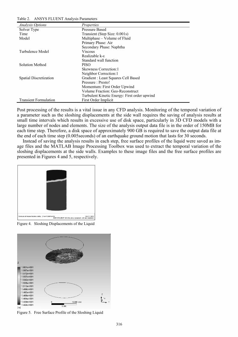
Table 2. ANSYS FLUENT Analysis Parameters Analysis Options Properties Solver Type Pressure Based Time Transient (Step Size: 0.001s) Model Multiphase – Volume of Fluid
Primary Phase: Air Secondary Phase: Naphtha
Turbulence Model Viscous Realizable k-ε Standard wall function
Solution Method PISO Skewness Correction:1 Neighbor Correction:1
Spatial Discretization Gradient : Least Squares Cell Based Pressure : Presto! Momentum: First Order Upwind Volume Fraction: Geo-Reconstruct Turbulent Kinetic Energy: First order upwind
Transient Formulation First Order Implicit Post processing of the results is a vital issue in any CFD analysis. Monitoring of the temporal variation of a parameter such as the sloshing displacements at the side wall requires the saving of analysis results at small time intervals which results in excessive use of disk space, particularly in 3D CFD models with a large number of nodes and elements. The size of the analysis output data file is in the order of 150MB for each time step. Therefore, a disk space of approximately 900 GB is required to save the output data file at the end of each time step (0.005seconds) of an earthquake ground motion that lasts for 30 seconds.
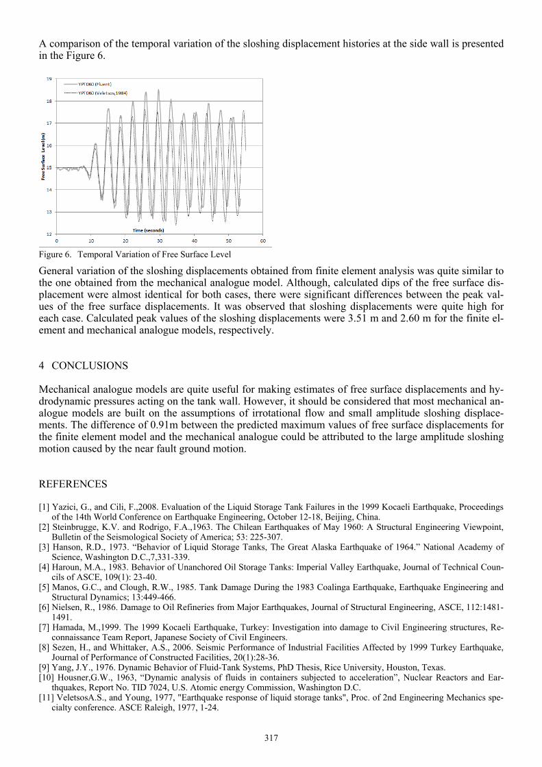
Instead of saving the analysis results in each step, free surface profiles of the liquid were saved as im-age files and the MATLAB Image Processing Toolbox was used to extract the temporal variation of the sloshing displacements at the side walls. Examples to these image files and the free surface profiles are presented in Figures 4 and 5, respectively.
Figure 4. Sloshing Displacements of the Liquid
Figure 5. Free Surface Profile of the Sloshing Liquid
316
A comparison of the temporal variation of the sloshing displacement histories at the side wall is presented in the Figure 6.
Figure 6. Temporal Variation of Free Surface Level
General variation of the sloshing displacements obtained from finite element analysis was quite similar to the one obtained from the mechanical analogue model. Although, calculated dips of the free surface dis-placement were almost identical for both cases, there were significant differences between the peak val-ues of the free surface displacements. It was observed that sloshing displacements were quite high for each case. Calculated peak values of the sloshing displacements were 3.51 m and 2.60 m for the finite el-ement and mechanical analogue models, respectively.
4 CONCLUSIONS
Mechanical analogue models are quite useful for making estimates of free surface displacements and hy-drodynamic pressures acting on the tank wall. However, it should be considered that most mechanical an-alogue models are built on the assumptions of irrotational flow and small amplitude sloshing displace-ments. The difference of 0.91m between the predicted maximum values of free surface displacements for the finite element model and the mechanical analogue could be attributed to the large amplitude sloshing motion caused by the near fault ground motion.
REFERENCES
[1] Yazici, G., and Cili, F.,2008. Evaluation of the Liquid Storage Tank Failures in the 1999 Kocaeli Earthquake, Proceedings of the 14th World Conference on Earthquake Engineering, October 12-18, Beijing, China.
[2] Steinbrugge, K.V. and Rodrigo, F.A.,1963. The Chilean Earthquakes of May 1960: A Structural Engineering Viewpoint, Bulletin of the Seismological Society of America; 53: 225-307.
[3] Hanson, R.D., 1973. “Behavior of Liquid Storage Tanks, The Great Alaska Earthquake of 1964.” National Academy of Science, Washington D.C.,7,331-339.
[4] Haroun, M.A., 1983. Behavior of Unanchored Oil Storage Tanks: Imperial Valley Earthquake, Journal of Technical Coun-cils of ASCE, 109(1): 23-40.
[5] Manos, G.C., and Clough, R.W., 1985. Tank Damage During the 1983 Coalinga Earthquake, Earthquake Engineering and Structural Dynamics; 13:449-466.
[6] Nielsen, R., 1986. Damage to Oil Refineries from Major Earthquakes, Journal of Structural Engineering, ASCE, 112:1481-1491.
[7] Hamada, M.,1999. The 1999 Kocaeli Earthquake, Turkey: Investigation into damage to Civil Engineering structures, Re-connaissance Team Report, Japanese Society of Civil Engineers.
[8] Sezen, H., and Whittaker, A.S., 2006. Seismic Performance of Industrial Facilities Affected by 1999 Turkey Earthquake, Journal of Performance of Constructed Facilities, 20(1):28-36.
[9] Yang, J.Y., 1976. Dynamic Behavior of Fluid-Tank Systems, PhD Thesis, Rice University, Houston, Texas. [10] Housner,G.W., 1963, “Dynamic analysis of fluids in containers subjected to acceleration”, Nuclear Reactors and Ear-
thquakes, Report No. TID 7024, U.S. Atomic energy Commission, Washington D.C. [11] VeletsosA.S., and Young, 1977, "Earthquake response of liquid storage tanks", Proc. of 2nd Engineering Mechanics spe-
cialty conference. ASCE Raleigh, 1977, 1-24.
317

[12] Haroun,M.A. and Housner,G.W., 1981, “Seismic design of liquid storage tanks”, Journal of Technical Councils of ASCE, Vol. 107, No. TC1, 191-207.
[13] Veletsos,A.S., 1984, "Seismic response and design of liquid storage tanks", Guidelines for Seismic design of oil & gas pi-pelines system, ASCE, NY, 255-370.
[14] Malhotra,P.K., Wenk,T., and Wieland,M., 2000, “Simple procedure for seismic analysis of liquid storage tanks”, Structu-ral Engineering, IABSE, Vol. 10, No.3, 197-201
[15] Jaiswal, O.R., Rai, D.C., and Jain, S.K., 2004. Review of Code Provisions on Seismic Analysis of Liquid Storage Tanks. IITK-GSDMA-EQ04-V1.0, IITK-GSDMA Project on Building Codes.
[16] ACI 350.3, 2001, “Seismic design of liquid containing concrete structures”, An American Concrete Institute Standard. [17] ACI 371, 1998, “Guide for the analysis, design and construction of concrete pedestal water towers”, An American Con-
crete Institute Standard. [18] API 650, 1998, “Welded storage tanks for oil storage”, American Petroleum Institute Standard, Washington D. C. [19] AWWA D-100, 1996, “Welded steel tanks for water storage”, American Water Works Association, Colorado. [20] AWWA D-103, 1997, “Factory-coated bolted steel tanks for water storage”, American Water Works Association, Colora-
do. [21] AWWA D-110, 1995, “Wire- and strand-wound circular, prestressed concrete water tanks”, American Water Works As-
sociation, Colorado. [22] AWWA D-115, 1995, “Circular prestressed concrete water tanks with circumferential tendons”, American Water Works
Association, Colorado. [23] NZS 3106, 1986, “Code of practice for concrete structures for the storage of liquids”, Standards Association of New Zea-
land, Wellington. [24] Eurocode 8, 1998, “Design provisions for earthquake resistance of structures, Part 1- General rules and Part 4 – Silos,
tanks and pipelines”, European committee for Standardization, Brussels. [25] IBC2012, 2012. “International Building Code”, International Code Council, Falls Church, Virginia. [26] Ibrahim, R.A. 2005. “Liquid Sloshing Dynamics: Theory and Applications”, Cambridge University Press, New York. [27] Dodge, F.T. 2000. “The New Dynamic Behavior of Liquids in Moving Containers”, SWRI, San Antonio, Texas. [28] Rebouillat, S. and Liksonov, D. 2010. “Fluid–structure interaction in partially filled liquid containers: A comparative revi-
ew of numerical approaches”, Computers and Fluids, 39(5):739-746. [29] ANSYS Fluent, 2011. User’s Guide Release 14.0, Ansys Inc. USA. [30] Chalhoub, M.S., and Kelly, J.M., 1988. Theoretical and experimental studies of cylindrical water tanks in base isolated
structures, Earthquake Engineering Research Center,Report No.UCB/EERC-88/07, College of Engineering, University of California at Berkeley.
[31] Yazici, G., 2008. Parametric Evaluation of the Seismic Response of Base-Isolated Upright Cylindrical Liquid Storage Tanks, PhD Dissertation, Graduate School of Science, Engineering and Technology, Istanbul Technical University, Istan-bul, Turkey.
318