icc-es evaluation report esr-3179 · esr-3179 | most widely accepted and trusted page 2 of 12...
TRANSCRIPT
ICC-ES Evaluation Reports are not to be construed as representing aesthetics or any other attributes not specifically addressed, nor are they to be construed as an endorsement of the subject of the report or a recommendation for its use. There is no warranty by ICC Evaluation Service, LLC, express or implied, as to any finding or other matter in this report, or as to any product covered by the report. Copyright © 2020 ICC Evaluation Service, LLC. All rights reserved. Page 1 of 12
ICC-ES Evaluation Report ESR-3179 Reissued October 2020
This report is subject to renewal October 2022.
www.icc-es.org | (800) 423-6587 | (562) 699-0543 A Subsidiary of the International Code Council ®
DIVISION: 06 00 00—WOOD, PLASTICS AND COMPOSITES
Section: 06 05 23—Wood, Plastic, and Composite Fastenings
REPORT HOLDER:
SCHRAUBENWERK GAISBACH GmbH (SWG) EVALUATION SUBJECT:
SWG ASSY 3.0 WOOD SCREWS 1.0 EVALUATION SCOPE
Compliance with the following codes:
2015, 2012, 2009 and 2006 International Building Code® (IBC)
2015, 2012, 2009 and 2006 International Residential Code® (IRC)
Property evaluated:
Structural
2.0 USES
SWG Assy 3.0 screws are alternate dowel-type threaded fasteners used in engineered wood-to-wood connections. The fasteners may be used under the IRC when an engineered design is submitted in accordance with IRC Section R301.1.3.
3.0 DESCRIPTION
3.1 General:
SWG Assy 3.0 screws have a gimlet point, and one of four head styles: hex (designated “Kombi”), washer (designated “SK”), flat head washer (FWH or SK II) or countersunk with milling pockets (designated ECO). The heads have a recess for use with an AW drive, which is a proprietary driving bit available from the report holder. The screws are available with nominal diameters of 1/4, 5/16, 3/8 and 1/2 inch (6, 8, 10 and 12 mm). The screws are partially threaded, and are available in varying lengths as shown in Table 1. Select screw lengths [(typically greater than 6 inches) (152 mm)] have a shank cutter design between the threads. The specified diameters and other dimensions are provided in Table 1 for each screw. The screws are available in boxes of loose fasteners.
3.2 Materials:
3.2.1 SWG Assy 3.0 Screws: All four types of SWG Assy 3.0 screws are manufactured from carbon steel. The Kombi,
SK and ECO types of Assy 3.0 screws are also manufactured from stainless steel.
3.2.1.1 Carbon Steel Screws: The screws are manufactured from carbon steel wire complying with the manufacturer’s specifications. After the heads are formed and the threads are rolled, the screws are hardened, in accordance with the manufacturer’s specifications. The hardened screws are then galvanized with a minimum zinc coating thickness of 0.0002 inch (5 µm) and coated with a lubricant. See Figures 1 through 4 for depictions of the screws.
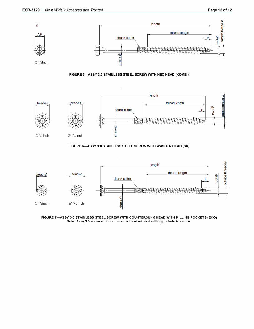
3.2.1.2 Stainless Steel Screws: The screws are manufactured from Grade A2 stainless steel wire complying with EN 10088-3 and EN 10263-5. In general, they have tighter thread pitch than carbon steel Assy 3.0 screws of the same nominal diameter. See Figures 5 through 7 for depictions of the screws.
3.2.2 Wood Members: Wood members may be sawn lumber or parallel strand lumber (PSL) which is a type of structural composite lumber (SCL). Sawn lumber side and main members must have a moisture content less than or equal to 19 percent at the time of screw installation and while in service. For PSL, the moisture content at the time of installation and in service must be in accordance with the applicable ICC-ES evaluation report on the PSL. Sawn lumber must have an assigned specific gravity, as specified in Table 12.3.3A of the 2015 ANSI/AWC National Design Specification for Wood Construction® (NDS-15) (Table 11.3.3A of NDS-12 for the 2012 IBC, Table 11.3.2A of NDS-05 for the 2009 and 2006 IBC) within the ranges given in the tables in this report. PSL must have a minimum equivalent specific gravity, given in the applicable ICC-ES evaluation report, of 0.50. The thickness of the wood main member, tm, must be equal to or greater than the screw length less the thickness of the side member, ts. The minimum thickness of both main and side members must also be as follows: 15/16 inch (24 mm) for 1/4-inch-diameter (6 mm) screws; 13/16 inches (30 mm) for 5/16-inch-diameter (8 mm) screws; 19/16 inches (40 mm) for 3/8-inch-diameter (10 mm) screws; and 33/16 inches (80 mm) for 1/2-inch-diameter (12 mm) screws.
4.0 DESIGN AND INSTALLATION
4.1 Design:
4.1.1 Governing Design Values: The allowable lateral load for a single-screw connection is the lesser of: (a) the reference lateral design value described in Section 4.1.2, adjusted by all applicable adjustment factors, and (b) the allowable screw shear strength given in Table 1. The

ESR-3179 | Most Widely Accepted and Trusted Page 2 of 12
allowable load for a single-screw connection in which the screw is subject to tension is the least of: (a) the reference withdrawal design value described in Section 4.1.3, adjusted by all applicable adjustment factors; (b) the reference head pull-through design value described in Section 4.1.3, adjusted by all applicable adjustment factors; and (c) the allowable screw tension strength given in Table 1.
4.1.2 Reference Lateral Design Values (Z): Reference lateral design values (Z) for single shear, wood-to-wood connections with the SWG Assy 3.0 carbon steel and stainless steel screws loaded parallel or perpendicular to grain may be determined in accordance with Section 12.3.1 of NDS-15 (Section 11.3.1 of NDS-12 for the 2012 IBC and NDS-05 for the 2009 and 2006 IBC) using the following parameters and limitations:
1. The applicable specified bending yield strength from Table 1 must be used for design.
2. The wood side member thickness must be a minimum of 13/4 inches (45 mm).
3. The minimum fastener penetration into the main member, excluding tip length, must be 6D.
4. For sawn lumber, the specific gravity used for design purposes must be the assigned specific gravity per Table 12.3.3.A of NDS-15 (Table 11.3.3A of NDS-12 for the 2012 IBC, Table 11.3.2A of NDS-05 for the 2009 and 2006 IBC).
5. For PSL, the specific gravity used for design purposes must be the equivalent specific gravity for the PSL given in the applicable ICC-ES evaluation report.
Reference lateral design values (Z) for select wood-to-wood connection configurations are given in Table 2.
4.1.3 Reference Withdrawal Design Values (W) and Head Pull-through (P) Design Values: Reference withdrawal design values (W) for SWG Assy 3.0 screws are given in Table 3. Reference head pull-through design values (P) are given in Table 4.
4.1.4 Adjustments to Reference Design Values: Reference design values must be adjusted in accordance with the requirements in Section 11.3 of NDS-15 (Section 10.3 of NDS-12 for the 2012 IBC and NDS-05 for the 2009 and 2006 IBC) for dowel-type fasteners. Use is limited to dry in-service conditions, such that the wet service factor, CM, is 1.0 in accordance with the NDS. The reference design values must also be adjusted in accordance with the requirements in Section 12.5 of NDS-15 (Section 11.5 of NDS-12 for the 2012 IBC and NDS-05 for the 2009 and 2006 IBC).
4.1.5 Connections with Multiple Screws: Connections containing multiple SWG Assy 3.0 screws must be designed in accordance with Sections 11.2.2 and 12.6 of NDS-15 (Sections 10.2.2 and 11.6 of NDS-12 for the 2012 IBC and NDS-05 for the 2009 and 2006 IBC).
4.1.6 Combined Loading: Where SWG Assy 3.0 screws are subjected to combined lateral and withdrawal loads, connections must be designed in accordance with Section 12.4.1 of NDS-15 (Section 11.4.1 of NDS-12 for the 2012 IBC and NDS-05 for the 2009 and 2006 IBC).
4.1.7 Capacity Requirements for Wood Members: When designing a connection, the structural members must be checked for load-carrying capacity in accordance with Section 11.1.2 of NDS-15 (Section 10.1.2 of NDS-12 for the 2012 IBC and NDS-05 for the 2009 and 2006 IBC), and local stresses within the connection must be checked against Appendix E of the NDS to ensure the capacity of the connection and fastener group.
4.2 Installation:
4.2.1 General: SWG Assy 3.0 screws must be installed in accordance with the manufacturer’s published installation instructions and this report. Screws must be installed such that their main axis is oriented perpendicular to the wood grain of side and main members. An appropriate screw length must be used, such that the screw will penetrate a minimum of 6 diameters into the main member for lateral connections; a minimum of 8 diameters into the main member for tension connections with carbon steel screws; and a minimum of 6 diameters into the main member for tension connections with stainless steel screws. The side member must be in direct contact with the main member, such that no gap exists between the wood members.
Screws must be installed using the manufacturer-recommended drive bit, with a rotary drill, or a percussion drill set to rotary only mode. Upon installation, the flat surface of the countersunk heads and the flat washer heads must be flush with the surface of the side member. The screws must not be overdriven.
4.2.2 End Distance, Edge Distance and Spacing: Minimum end distances, edge distances and spacing of the screws must be sufficient to prevent splitting of the wood, or as required by Table 5, whichever is greater. When the screws are used in PSL, the minimum fastener end and edge distances and spacing must be in accordance with Table 5 or in accordance with the ICC-ES evaluation report on the PSL, whichever is more restrictive.
4.2.3 Pilot Holes: Typical installation of SWG Assy 3.0 screws does not require predrilling of the wood members; however, predrilling of holes to reduce splitting is recommended by the manufacturer for the following conditions:
1. For species which are prone to splitting, including various species of spruce and fir, including Douglas fir.
2. For lumber with thickness ≤ 11/2 inches (35 mm).
3. For laterally loaded screws installed in lumber with a thickness ≤ 7D (≤ 14D for various species of spruce and fir, including Douglas fir).
4. For axially loaded screws installed in lumber with a thickness ≤ 10D and/or a width of less than 8D or 60 mm (23/8 inches), whichever is greater.
For recommended sizes of predrilled holes, see Table 6.
5.0 CONDITIONS OF USE
The SWG Assy 3.0 screws described in this report comply with, or are suitable alternatives to what is specified in, those codes listed in Section 1.0 of this report, subject to the following conditions:
5.1 The screws must be installed in accordance with the manufacturer’s published installation instructions and this report. In case of a conflict between this report and the manufacturer’s installation instructions, this report governs.
5.2 Calculations and details demonstrating compliance with this report must be submitted to the code official. The calculations and details must be prepared by a registered design professional where required by the statutes of the jurisdiction in which the project is to be constructed.
5.3 SWG Assy 3.0 screws must be installed and used in dry in-service conditions where the moisture content of the wood members does not exceed 19 percent.
5.4 Use of the screws in contact with preservative-treated or fire-retardant-treated wood is outside the scope of this report.

ESR-3179 | Most Widely Accepted and Trusted Page 3 of 12
5.5 Assy 3.0 screws are manufactured under a quality control program with inspections by ICC-ES.
6.0 EVIDENCE SUBMITTED
Data in accordance with the ICC-ES Acceptance Criteria for Alternate Dowel-type Threaded Fasteners (AC233), dated April 2015 (editorially revised August 2015).
7.0 IDENTIFICATION
7.1 Individual SWG Assy 3.0 screws are identified in the field by their unique configurations. In addition, the screw heads are marked with the letters “ASSY”, and may be marked with the screw length, as shown in Figures 1 through 7. Packages of screws are identified with the manufacturer’s name (SWG); product name (Assy 3.0); head type and drive size; screw diameter and length (in both inches and millimeters); and the evaluation report number (ESR-3179).
7.2 The report holder’s contact information is the following:
SCHRAUBENWERK GAISBACH GmbH (SWG) AM BAHNHOF 50 D-74638 WALDENBURG GERMANY +49 7942 1000 [email protected] www.swg-produktion.de Technical Support: MYTICON TIMBER CONNECTORS INC. (866) 899-4090 [email protected] www.my-ti-con.com

ESR-3179 | Most Widely Accepted and Trusted Page 4 of 12
TABLE 1—FASTENER SPECIFICATIONS AND STRENGTHS – SWG ASSY 3.0 SCREWS
NOMINAL
DIAMETER (inch)
HEAD STYLE
OUTSIDE THREAD
DIAMETER
(inch)
ROOT
DIAMETER (inch)
SMOOTH SHANK
DIAMETER (inch)
THREAD PITCH (inch)
HEAD DIAMETER
(inch)
DRIVE TYPE AND SIZE
OVERALL LENGTH1 (inches)
THREAD LENGTH
(inch)
TIP LENGTH
(inch)
SPECIFIED BENDING YIELD STRENGTH2, Fyb
(psi)
ALLOWABLE FASTENER STRENGTH
Tension (lbf)
Shear (lbf)
CA
RB
ON
ST
EE
L
1/4
Washer (SK)
See Figure 2 0.236 0.154 0.173 0.142 0.551 AW 30
23/4 15/8
0.236 169,500 1150 685
31/8 to 31/2 2
37/8 23/8
43/8 to 113/4 23/4
Countersunk (ECO)
See Figure 3 0.236 0.154 0.173 0.142 0.472 AW 30
23/4 15/8
31/8 to 31/2 2
37/8 23/8
43/8 to 113/4 23/4
5/16
Hex (Kombi)
See Figure 1 0.315 0.209 0.228 0.220
0.467 (width
between parallel edges)
AW 40 or
12 mm hex
socket
31/8 to 31/2 2
0.315 150,200 1950 1320
37/8 23/8
43/8 to 77/8 31/8
85/8 to 311/2 37/8
Washer (SK)
See Figure 2 0.315 0.209 0.228 0.220 0.866 AW 40
31/8 to 31/2 2
37/8 23/8
43/8 to 77/8 31/8
85/8 to 311/2 37/8
Countersunk (ECO)
See Figure 3 0.315 0.209 0.228 0.220 0.581 AW 40
31/8 to 31/2 2
37/8 23/8
43/8 to 77/8 31/8
85/8 to 311/2 37/8
Flat Washer (FWH or
SK II) See Figure 4
0.315 0.209 0.228 0.220 0.719 AW40
13/4 11/4
2 to 23/16 19/16
23/8 to 31/2 2
37/8 23/8
43/8 to 77/8 31/8
85/8 to 311/2 37/8
ESR-3179 | Most Widely Accepted and Trusted Page 5 of 12
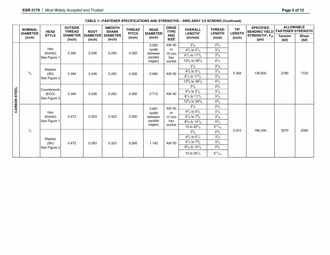
TABLE 1—FASTENER SPECIFICATIONS AND STRENGTHS – SWG ASSY 3.0 SCREWS (Continued)
NOMINAL DIAMETER
(inch)
HEAD STYLE
OUTSIDE THREAD
DIAMETER
(inch)
ROOT
DIAMETER (inch)
SMOOTH SHANK
DIAMETER (inch)
THREAD PITCH (inch)
HEAD DIAMETER
(inch)
DRIVE TYPE AND SIZE
OVERALL LENGTH1 (inches)
THREAD LENGTH
(inch)
TIP LENGTH
(inch)
SPECIFIED BENDING YIELD STRENGTH2, Fyb
(psi)
ALLOWABLE FASTENER STRENGTH
Tension (lbf)
Shear (lbf)
CA
RB
ON
ST
EE
L
3/8
Hex (Kombi)
See Figure 1 0.394 0.248 0.283 0.260
0.583 (width
between parallel edges)
AW 40 or
15 mm hex
socket
37/8 23/8
0.394 136,600 2780 1725
43/4 to 51/2 31/8
61/4 to 113/4 37/8
125/8 to 393/8 43/4
Washer (SK)
See Figure 2 0.394 0.248 0.283 0.260 0.984 AW 50
37/8 23/8
43/4 to 51/2 31/8
61/4 to 113/4 37/8
125/8 to 393/8 43/4
Countersunk (ECO)
See Figure 3 0.394 0.248 0.283 0.260 0.713 AW 40
37/8 23/8
43/4 to 51/2 31/8
61/4 to 113/4 37/8
125/8 to 393/8 43/4
1/2
Hex (Kombi)
See Figure 1 0.472 0.283 0.323 0.260
0.661 (width
between parallel edges)
AW 40 or
17 mm hex
socket
37/8 23/8
0.472 166,300 3070 2095
43/4 to 51/2 31/8
61/4 to 78/8 37/8
85/8 to 141/8 43/4
15 to 201/2 511/16
Washer (SK)
See Figure 2 0.472 0.283 0.323 0.260 1.142 AW 50
37/8 23/8
43/4 to 51/2 31/8
61/4 to 78/8 37/8
85/8 to 141/8 43/4
15 to 201/2 511/16
ESR-3179 | Most Widely Accepted and Trusted Page 6 of 12
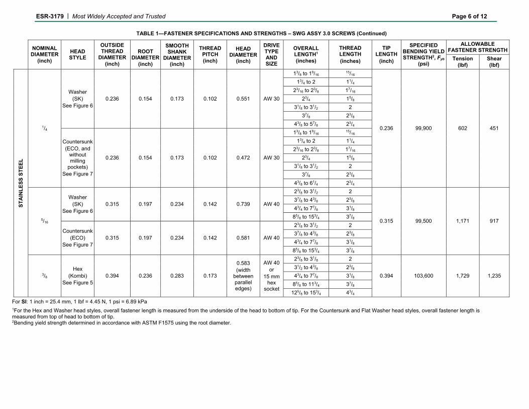
TABLE 1—FASTENER SPECIFICATIONS AND STRENGTHS – SWG ASSY 3.0 SCREWS (Continued)
NOMINAL
DIAMETER (inch)
HEAD STYLE
OUTSIDE THREAD
DIAMETER
(inch)
ROOT
DIAMETER (inch)
SMOOTH SHANK
DIAMETER (inch)
THREAD PITCH (inch)
HEAD DIAMETER
(inch)
DRIVE TYPE AND SIZE
OVERALL LENGTH1 (inches)
THREAD LENGTH (inches)
TIP LENGTH
(inch)
SPECIFIED BENDING YIELD STRENGTH2, Fyb
(psi)
ALLOWABLE FASTENER STRENGTH
Tension (lbf)
Shear (lbf)
ST
AIN
LE
SS
ST
EE
L
1/4
Washer (SK)
See Figure 6 0.236 0.154 0.173 0.102 0.551 AW 30
13/8 to 19/16 15/16
0.236 99,900 602 451
13/4 to 2 11/4
23/16 to 23/8 17/16
23/4 15/8
31/8 to 31/2 2
37/8 23/8
43/8 to 57/8 23/4
Countersunk (ECO, and
without milling
pockets) See Figure 7
0.236 0.154 0.173 0.102 0.472 AW 30
13/8 to 19/16 15/16
13/4 to 2 11/4
23/16 to 23/8 17/16
23/4 15/8
31/8 to 31/2 2
37/8 23/8
43/8 to 61/4 23/4
5/16
Washer (SK)
See Figure 6 0.315 0.197 0.234 0.142 0.739 AW 40
23/8 to 31/2 2
0.315 99,500 1,171 917
37/8 to 43/8 23/8
43/4 to 77/8 31/8
85/8 to 153/4 37/8
Countersunk (ECO)
See Figure 7 0.315 0.197 0.234 0.142 0.581 AW 40
23/8 to 31/2 2
37/8 to 43/8 23/8
43/4 to 77/8 31/8
85/8 to 153/4 37/8
3/8 Hex
(Kombi) See Figure 5
0.394 0.236 0.283 0.173
0.583 (width
between parallel edges)
AW 40 or
15 mm hex
socket
23/8 to 31/8 2
0.394 103,600 1,729 1,235
31/2 to 43/8 23/8
43/4 to 77/8 31/8
85/8 to 113/4 37/8
125/8 to 153/4 43/4
For SI: 1 inch = 25.4 mm, 1 lbf = 4.45 N, 1 psi = 6.89 kPa 1For the Hex and Washer head styles, overall fastener length is measured from the underside of the head to bottom of tip. For the Countersunk and Flat Washer head styles, overall fastener length is measured from top of head to bottom of tip. 2Bending yield strength determined in accordance with ASTM F1575 using the root diameter.

ESR-3179 | Most Widely Accepted and Trusted Page 7 of 12
TABLE 2—REFERENCE LATERAL DESIGN VALUES (Z)1,2,3,4,5
FASTENER DESIGNATION1
SIDE MEMBER
THICKNESS (inches)
FASTENER PENETRATION
INTO MAIN MEMBER (inches)
REFERENCE LATERAL DESIGN VALUE, Z (lbf) FOR SPECIFIC GRAVITIES OF
0.33 0.42 0.49 0.55
Z‖ Z⊥/‖ Z⊥ Z‖ Z⊥/‖ Z⊥ Z‖ Z⊥/‖ Z⊥ Z‖ Z⊥/‖ Z⊥
CA
RB
ON
ST
EE
L S
CR
EW
S
1/4" x 4" 2 13/4 131 131 131 185 185 185 213 213 213 237 237 2371/4" x 43/4" 2 21/2 142 142 142 185 185 185 213 213 213 237 237 2371/4" x 51/2" 23/4 21/2 148 148 148 185 185 185 213 213 213 237 237 2371/4" x 61/4" 31/2 21/2 148 148 148 185 185 185 213 213 213 237 237 2371/4" x 71/8" 4 27/8 148 148 148 185 185 185 213 213 213 237 237 2371/4" x 77/8" 51/2 21/8 148 148 148 185 185 185 213 213 213 237 237 2371/4" x 85/8" 6 23/8 148 148 148 185 185 185 213 213 213 237 237 2371/4" x 91/2" 7 21/4 148 148 148 185 185 185 213 213 213 237 237 237
1/4" x 113/4" 71/2 4 148 148 148 185 185 185 213 213 213 237 237 2371/4" x 113/4" 8 31/2 148 148 148 185 185 185 213 213 213 237 237 2371/4" x 113/4" 9 21/2 148 148 148 185 185 185 213 213 213 237 237 2375/16" x 43/4" 2 27/16 164 131 131 234 187 187 280 224 224 311 249 249 5/16" x 51/2" 23/4 27/16 185 148 148 243 194 194 280 224 224 311 249 249 5/16" x 61/4" 23/4 33/16 194 156 156 243 194 194 280 224 224 311 249 249 5/16" x 71/8" 31/2 35/16 194 156 156 243 194 194 280 224 224 311 249 249 5/16" x 71/8" 4 213/16 194 156 156 243 194 194 280 224 224 311 249 249 5/16" x 85/8" 51/2 213/16 194 156 156 243 194 194 280 224 224 311 249 249 5/16" x 91/2" 6 33/16 194 156 156 243 194 194 280 224 224 311 249 249
5/16" x 101/4" 7 215/16 194 156 156 243 194 194 280 224 224 311 249 249 5/16" x 11" 71/2 33/16 194 156 156 243 194 194 280 224 224 311 249 249
5/16" x 125/8" 8 45/16 194 156 156 243 194 194 280 224 224 311 249 249 5/16" x 133/8" 9 41/16 194 156 156 243 194 194 280 224 224 311 249 249 5/16" x 141/8" 10 313/16 194 156 156 243 194 194 280 224 224 311 249 249 5/16" x 153/4" 11 47/16 194 156 156 243 194 194 280 224 224 311 249 249 5/16" x 163/8" 12 41/16 194 156 156 243 194 194 280 224 224 311 249 249 5/16" x 187/8" 14 47/16 194 156 156 243 194 194 280 224 224 311 249 249
3/8" x 51/2" 2 31/8 292 180 160 353 227 213 396 265 252 419 300 288 3/8" x 51/2" 23/4 23/8 310 194 154 366 260 219 396 292 273 419 314 297 3/8" x 61/4" 23/4 31/8 325 208 176 366 265 244 396 292 273 419 314 297 3/8" x 61/4" 31/2 23/8 323 217 178 366 265 233 396 292 273 419 314 297 3/8" x 71/8" 31/2 31/4 325 227 202 366 265 244 396 292 273 419 314 297 3/8" x 71/8" 4 23/4 325 227 193 366 265 244 396 292 273 419 314 297 3/8" x 77/8" 4 31/2 325 227 205 366 265 244 396 292 273 419 314 297 3/8" x 85/8" 51/2 23/4 325 227 193 366 265 244 396 292 273 419 314 297 3/8" x 91/2" 51/2 35/8 325 227 205 366 265 244 396 292 273 419 314 297
3/8" x 113/4" 6 53/8 325 227 205 366 265 244 396 292 273 419 314 297 3/8" x 113/4" 7 43/8 325 227 205 366 265 244 396 292 273 419 314 297 3/8" x 125/8" 71/2 43/4 325 227 205 366 265 244 396 292 273 419 314 297 3/8" x 133/8" 8 5 325 227 205 366 265 244 396 292 273 419 314 297 3/8" x 133/8" 81/2 51/4 325 227 205 366 265 244 396 292 273 419 314 297 3/8" x 141/8" 9 55/8 325 227 205 366 265 244 396 292 273 419 314 297 3/8" x 141/8" 91/2 51/8 325 227 205 366 265 244 396 292 273 419 314 297
3/8" x 15" 10 45/8 325 227 205 366 265 244 396 292 273 419 314 297 3/8" x 153/4" 11 43/8 325 227 205 366 265 244 396 292 273 419 314 297 3/8" x 163/8" 111/2 41/2 325 227 205 366 265 244 396 292 273 419 314 297 3/8" x 171/4" 12 47/8 325 227 205 366 265 244 396 292 273 419 314 297 3/8" x 181/8" 13 43/4 325 227 205 366 265 244 396 292 273 419 314 297 3/8" x 201/2" 14 61/8 325 227 205 366 265 244 396 292 273 419 314 297 1/2" x 71/8" 31/2 31/8 456 278 212 526 372 301 569 412 377 602 443 412 1/2" x 77/8" 31/2 37/8 467 289 236 526 374 335 569 412 379 602 443 412 1/2" x 77/8" 4 33/8 467 307 237 526 374 337 569 412 379 602 443 412 1/2" x 91/2" 51/2 31/2 467 320 265 526 374 339 569 412 379 602 443 412
1/2" x 101/4" 51/2 41/4 467 320 285 526 374 339 569 412 379 602 443 412
ESR-3179 | Most Widely Accepted and Trusted Page 8 of 12
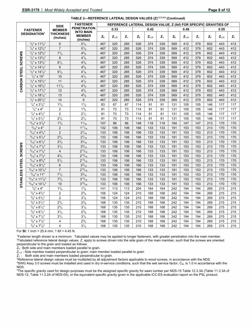
TABLE 2—REFERENCE LATERAL DESIGN VALUES (Z)1,2,3,4,5 (Continued)
FASTENER DESIGNATION1
SIDE MEMBER
THICKNESS (inches)
FASTENER PENETRATION
INTO MAIN MEMBER (inches)
REFERENCE LATERAL DESIGN VALUE, Z (lbf) FOR SPECIFIC GRAVITIES OF
0.33 0.42 0.49 0.55
Z‖ Z⊥/‖ Z⊥ Z‖ Z⊥/‖ Z⊥ Z‖ Z⊥/‖ Z⊥ Z‖ Z⊥/‖ Z⊥
CA
RB
ON
ST
EE
L S
CR
EW
S
1/2" x 113/4" 6 51/4 467 320 285 526 374 339 569 412 379 602 443 412 1/2" x 125/8" 7 51/8 467 320 285 526 374 339 569 412 379 602 443 412 1/2" x 125/8" 71/2 45/8 467 320 285 526 374 339 569 412 379 602 443 412 1/2" x 133/8" 8 47/8 467 320 285 526 374 339 569 412 379 602 443 412 1/2" x 133/8" 81/2 43/8 467 320 285 526 374 339 569 412 379 602 443 412 1/2" x 141/8" 9 45/8 467 320 285 526 374 339 569 412 379 602 443 412 1/2" x 141/8" 91/2 41/8 467 320 285 526 374 339 569 412 379 602 443 412
1/2" x 15" 10 41/2 467 320 285 526 374 339 569 412 379 602 443 412 1/2" x 153/4" 11 41/4 467 320 285 526 374 339 569 412 379 602 443 412 1/2" x 163/8" 111/2 43/8 467 320 285 526 374 339 569 412 379 602 443 412 1/2" x 171/4" 12 43/4 467 320 285 526 374 339 569 412 379 602 443 412 1/2" x 181/8" 13 45/8 467 320 285 526 374 339 569 412 379 602 443 412 1/2" x 201/2" 14 6 467 320 285 526 374 339 569 412 379 602 443 412
ST
AIN
LE
SS
ST
EE
L S
CR
EW
S
1/4" x 31/8" 13/4 11/8 83 67 67 114 91 91 131 105 105 146 117 117 1/4" x 4" 2 13/4 91 73 73 114 91 91 131 105 105 146 117 117
1/4" x 43/4" 2 21/2 91 73 73 114 91 91 131 105 105 146 117 117 1/4" x 51/2" 23/4 21/2 91 73 73 114 91 91 131 105 105 146 117 117 5/16" x 31/8" 13/4 11/16 107 86 86 148 118 118 184 147 147 213 170 170
5/16" x 4" 2 111/16 132 106 106 166 133 133 191 153 153 213 170 170 5/16" x 43/4" 2 27/16 133 106 106 166 133 133 191 153 153 213 170 170 5/16" x 51/2" 23/4 27/16 133 106 106 166 133 133 191 153 153 213 170 170 5/16" x 61/4" 23/4 33/16 133 106 106 166 133 133 191 153 153 213 170 170 5/16" x 71/8" 31/2 35/16 133 106 106 166 133 133 191 153 153 213 170 170 5/16" x 71/8" 4 213/16 133 106 106 166 133 133 191 153 153 213 170 170 5/16" x 77/8" 43/4 213/16 133 106 106 166 133 133 191 153 153 213 170 170 5/16" x 85/8" 51/2 213/16 133 106 106 166 133 133 191 153 153 213 170 170 5/16" x 91/2" 6 33/16 133 106 106 166 133 133 191 153 153 213 170 170
5/16" x 101/4" 7 215/16 133 106 106 166 133 133 191 153 153 213 170 170 5/16" x 11" 71/2 33/16 133 106 106 166 133 133 191 153 153 213 170 170
5/16" x 117/8" 73/4 313/16 133 106 106 166 133 133 191 153 153 213 170 170 5/16" x 141/4" 10 315/16 133 106 106 166 133 133 191 153 153 213 170 170
3/8" x 4" 13/4 17/8 141 113 113 204 164 164 242 194 194 269 215 215 3/8" x 43/4" 2 23/8 156 124 124 210 168 168 242 194 194 269 215 215 3/8" x 51/2" 2 31/8 156 124 124 210 168 168 242 194 194 269 215 215 3/8" x 51/2" 23/4 23/8 168 135 135 210 168 168 242 194 194 269 215 215 3/8" x 61/4" 23/4 31/8 168 135 135 210 168 168 242 194 194 269 215 215 3/8" x 61/4" 31/2 23/8 168 135 135 210 168 168 242 194 194 269 215 215 3/8" x 71/8" 31/2 31/4 168 135 135 210 168 168 242 194 194 269 215 215 3/8" x 71/8" 4 23/4 168 135 135 210 168 168 242 194 194 269 215 215 3/8" x 77/8" 4 31/2 168 135 135 210 168 168 242 194 194 269 215 215
For SI: 1 inch = 25.4 mm, 1 lbf = 4.45 N. 1Fastener length shown is a minimum. Tabulated values may be applied to longer fasteners, with greater penetration into the main member. 2Tabulated reference lateral design values, Z, apply to screws driven into the side grain of the main member, such that the screws are oriented perpendicular to the grain and loaded as follows: Z‖ : Both side and main members loaded parallel to grain. Z⊥/‖ : Side member loaded perpendicular to grain; main member loaded parallel to grain Z⊥ : Both side and main members loaded perpendicular to grain. 3Reference lateral design values must be multiplied by all adjustment factors applicable to wood screws, in accordance with the NDS. 4SWG Assy 3.0 screws must be installed and used in dry in-service conditions, such that the wet service factor, CM, is 1.0 in accordance with the NDS. 5The specific gravity used for design purposes must be the assigned specific gravity for sawn lumber per NDS-15 Table 12.3.3A (Table 11.3.3A of NDS-12, Table 11.3.2A of NDS-05), or the equivalent specific gravity given in the applicable ICC-ES evaluation report on the PSL product.

ESR-3179 | Most Widely Accepted and Trusted Page 9 of 12
TABLE 3—REFERENCE WITHDRAWAL DESIGN VALUES (W)1,2,3,4 lbf/in
NOMINAL FASTENER DIAMETER
(inch)
FOR SPECIFIC GRAVITIES (SG) AND EQUIVALENT SPECIFIC GRAVITIES (ESG) OF: 5
SG = 0.55 SG = 0.49 SG = 0.42 SG = 0.35 ESG ≥ 0.50
Carbon Steel Screws1/4 230 202 169 137 156 5/16 279 248 212 176 179 3/8 317 280 237 190 211 1/2 334 297 254 211 223
Stainless Steel Screws1/4 n/a 162 143 n/a n/a 5/16
n/a 211 169 n/a n/a 3/8 n/a 211 180 n/a n/a
For SI: 1 inch = 25.4 mm, 1 lbf = 4.45 N. 1Tabulated reference withdrawal design values, W, apply to screws driven into the side grain of the main member, such that the screws are oriented perpendicular to the grain and loaded in direct withdrawal. 2Values must be multiplied by all adjustment factors applicable to wood screws, in accordance with the NDS. 3SWG Assy 3.0 screws must be installed and used in dry in-service conditions, such that the wet service factor, CM, is 1.0 in accordance with the NDS. 4Reference withdrawal design values are to be multiplied by the length of thread penetration into the main member. Main member penetration must be at least 8 times the nominal diameter. Threaded length must not include the length of the tip. 5The specific gravity used for design purposes must be the assigned specific gravity for sawn lumber per NDS-15 Table 12.3.3A (Table 11.3.3A of NDS-12, Table 11.3.2A of NDS-05), and the equivalent specific gravity (ESG) must be the equivalent specific gravity given in the applicable ICC-ES evaluation report on the PSL product.
TABLE 4—REFERENCE HEAD PULL-THROUGH DESIGN VALUES (P)1,2,3 lbf
NOMINAL FASTENER DIAMETER
(inches)
HEAD TYPE
MINIMUM SIDE MEMBER
THICKNESS, ts (inches)
FOR SPECIFIC GRAVITIES (SG) AND EQUIVALENT SPECIFIC GRAVITIES (ESG) OF: 4
SG = 0.55 SG = 0.49 SG = 0.42 SG = 0.35 ESG ≥ 0.50
Carbon Steel Screws
1/4 Washer
13/8
407 356 299 244 440 Countersunk 221 194 163 133 262
5/16
Hex 275 233 188 146 326 Washer 685 604 510 410 732
Countersunk 318 277 232 187 327 Flat Washer n/a 480 406 n/a n/a
3/8 Hex 369 327 278 225 420
Washer 710 660 593 513 797 Countersunk 445 385 319 246 509
1/2 Hex 390 351 305 257 474
Washer 834 738 627 517 939 Stainless Steel Screws
1/4 Washer
13/8
407 356 299 244 440 Countersunk 221 194 163 133 262
5/16 Washer 685 604 510 410 732
Countersunk n/a 524 445 n/a n/a 3/8 Hex 369 327 278 225 420
For SI: 1 inch = 25.4 mm, 1 lbf = 4.45 N. 1Tabulated head pull-through design values, P, must be multiplied by all adjustment factors applicable to wood screw withdrawal, in accordance with the NDS. 2Design values apply to connections with minimum side member thicknesses, ts, as given above. 3SWG Assy 3.0 screws must be installed and used in dry in-service conditions, such that the wet service factor, CM, is 1.0 in accordance with the NDS. 4The specific gravity (SG) used for design purposes must be the assigned specific gravity for sawn lumber per NDS-15 Table 12.3.3A (Table 11.3.3A of NDS-12, Table 11.3.2A of NDS-05), and the equivalent specific gravity (ESG) must be the equivalent specific gravity given in the applicable ICC-ES evaluation report on PSL product.

ESR-3179 | Most Widely Accepted and Trusted Page 10 of 12
TABLE 5—CONNECTION GEOMETRY REQUIREMENTS FOR SAWN LUMBER AND PSL1
CONDITION
MINIMUM DIMENSION (in terms of nominal screw diameter, D)
LATERALLY LOADED SCREWS AXIALLY LOADED SCREWS
SG ≤ 0.42 0.42 < SG ≤ 0.55
and PSL SG ≤ 0.42
0.42 < SG ≤ 0.55 and PSL
End distance 10D 15D (22.5D in D-Fir) 10D 15D (22.5D in D-Fir)
Edge distance
Lateral Loading parallel to grain
5D 7D - -
Lateral Loading perpendicular to grain
10D 12D - -
Axial Load on fastener - - 5D 7D
Spacing between fasteners in a row 5D 7D (10.5D in D-Fir) 5D 7D (10.5D in D-Fir)
Spacing between rows
Loading parallel or perpendicular to grain
5D 7D - -
Axial Load on fastener - - 5D 7D
1End distances, edge distances and screw spacing must be sufficient to prevent splitting of the wood, or as required by this table or the ICC-ES evaluation report on the PSL, whichever is the more restrictive. 2D-Fir refers to species group Douglas fir- Larch.
TABLE 6—RECOMMENDED DIAMETER OF PREDRILLED HOLES1 inches
NOMINAL FASTENER DIAMETER
(mm) [inches]
APPLICABLE LOAD CONDITION AND SPECIFIC GRAVITY
Screws Subject to Lateral Load Screws Loaded Axially
SG ≤ 0.5 SG > 0.5 and PSL 0.35 ≤ SG ≤ 0.55 and
PSL 1/4 5/32 5/32 5/32
5/16 13/64 7/32 13/64
3/8 15/64 1/4 15/64
1/2 17/64 5/16 17/64
For SI: 1 inch = 25.4 mm.

ESR-3179 | Most Widely Accepted and Trusted Page 11 of 12
FIGURE 1—ASSY 3.0 CARBON STEEL SCREW WITH HEX HEAD (KOMBI)
FIGURE 2—ASSY 3.0 CARBON STEEL SCREW WITH WASHER HEAD (SK)
FIGURE 3—ASSY 3.0 CARBON STEEL SCREW WITH COUNTERSUNK HEAD WITH MILLING POCKETS (ECO)
FIGURE 4—ASSY 3.0 CARBON STEEL SCREW WITH FLAT WASHER HEAD (FWH OR SK II)
1/4 inch 5/16 ; 3/8 ; 1/2 inch
5/16 ; 3/8 ; 1/2 inch
5/16 inch
1/4 inch 5/16 ; 3/8 inch
ESR-3179 | Most Widely Accepted and Trusted Page 12 of 12
FIGURE 5—ASSY 3.0 STAINLESS STEEL SCREW WITH HEX HEAD (KOMBI)
FIGURE 6—ASSY 3.0 STAINLESS STEEL SCREW WITH WASHER HEAD (SK)
FIGURE 7—ASSY 3.0 STAINLESS STEEL SCREW WITH COUNTERSUNK HEAD WITH MILLING POCKETS (ECO)
Note: Assy 3.0 screw with countersunk head without milling pockets is similar.
1/4 inch 5/16 inch
1/4 inch 5/16 inch
3/8 inch