ic2-print
DESCRIPTION
good lectureTRANSCRIPT

Internal Combustion EnginesUniversity of Al-Basrah
College of Engineering Mechanical Engineering Department
3rd Stage
II. Engine Power and Performance
�
�Automotive systems. Note location of parts. Study flow of fuel, air, exhaust and power.
�
Preliminary Notes
• Internal combustion engines are so called because the heat required to drive them is released by oxidizing a fuel inside the engine itself.
• This approach has advantages and disadvantages, but is still the most popular for transport and small power generation plant.
• We will be looking at some common types of engine, examining ways of analyzing their performance parameters, and some of the problems encountered in improving efficiency and output .
�
Preliminary Notes
• Internal combustion engines include systems which function like "closed“ systems ( e.g. petrol engines) or as "open" ( e.g. gas turbines) . systems
All the engines we will examine contain the same basic activities:
���������������� ���������������������������������������������������� ������������������������������������������ ���������������������������������
�

Review of Otto Cycle• The Otto Cycle has four basic
steps or strokes:� F-A : An intake stroke that draws
a combustible mixture of fuel and air into the cylinder
� A-B : A compression stroke with the valves closed which raises the temperature of the mixture. A spark ignites the mixture towards the end of this stroke.
� C-D : An expansion or power stroke. Resulting from combustion.
� E-F : An Exhaust stroke that pushes the burned contents out of the cylinder
idealized representation of the Otto cycle on a PV diagram.
�
Otto (SI Engine) Operating Cycle
TC0o
Crank-Shaft
�
180o
BC
270o 90o
1 atm
Cylinder Volume(displacement)
1 power stroke for every 2 crank shaft revolutions
�

Engine Geometric Parameters• For an engine with bore (d); crank
offset (r), stroke length L, turning at an engine speed of N:
L = 2 r • An average piston speed is
• Average piston speed for all engines will normally be in the range of 5 to 15 m/sec with large diesel engines on the low end and high-performance automobile engines on the high end. .....Why?
LNU p 2�
d
r
�
Engine Geometry Parameters
r
d
�� 222 sincos. rlrs ���
• The distance (s) between crank axis and gudgeon pin axis is given by
• The cylinder volume (V) at any crank angle is
•maximum displacement or swept volume of one cylinder is
• Cylinder volume (V) at any crank angle can also written in dimensionless form as
� �srldVV c ����4
2�
TDCBDCd VVLdV ���4
2�
�
��
���
��
��������� �� 2
2
sincos1)1(211/
rl
rlCRVV c

Engine Geometry Parameters• The combustion chamber surface area is
• Where Ach is the cylinder head surface area, Ap is the piston-face area. Ach will be somewhat larger than Ap
• The instantaneous piston speed, Up = ds/dt
• Average piston speed for standard high performance auto engine is about (2L N = 15 m/s). Therefore engines with large strokes run at lower speeds those with small strokes run at higher speeds.
� �
�
��
���
��
�������
��
������
�����
���
�
22
sincos12 r
lrldLAAA
srldAAA
pchs
pchs
� �
�
��
�
��
�
�
��
�
�
���
�
���22 sin
cos1sin2
/rl
UU pp
Piston Velocity vs. Crank Angle
• R is the ratio of connecting rod length to crank offset and usually has values of 3 to 4 for small engines, increasing to 5 to 10 for the largest engine. The effect of R on piston speed is shown in the figure.
��
R = l/r

The 1st Law Analysis of Engine Cycle
��
Reciprocating Engine as an Open System
Energy Flow through the Reciprocating
Engine
Measurement of Engine Torque and Power• Torque requires the
measurement of a force acting through a distance. Any apparatus that permits such a measurement is called a dynamometer.
• All dynamometers operate on the principle illustrated in the figure shown .
• The rotor (a), driven by the engine to be tested, is coupled (electrically, magnetically, hydraulically or by dry friction) to the stator (b) .
• The “scale” shown can be a beam balance or a load cell which has an output either hydraulic pressure or an electrical voltage.
��
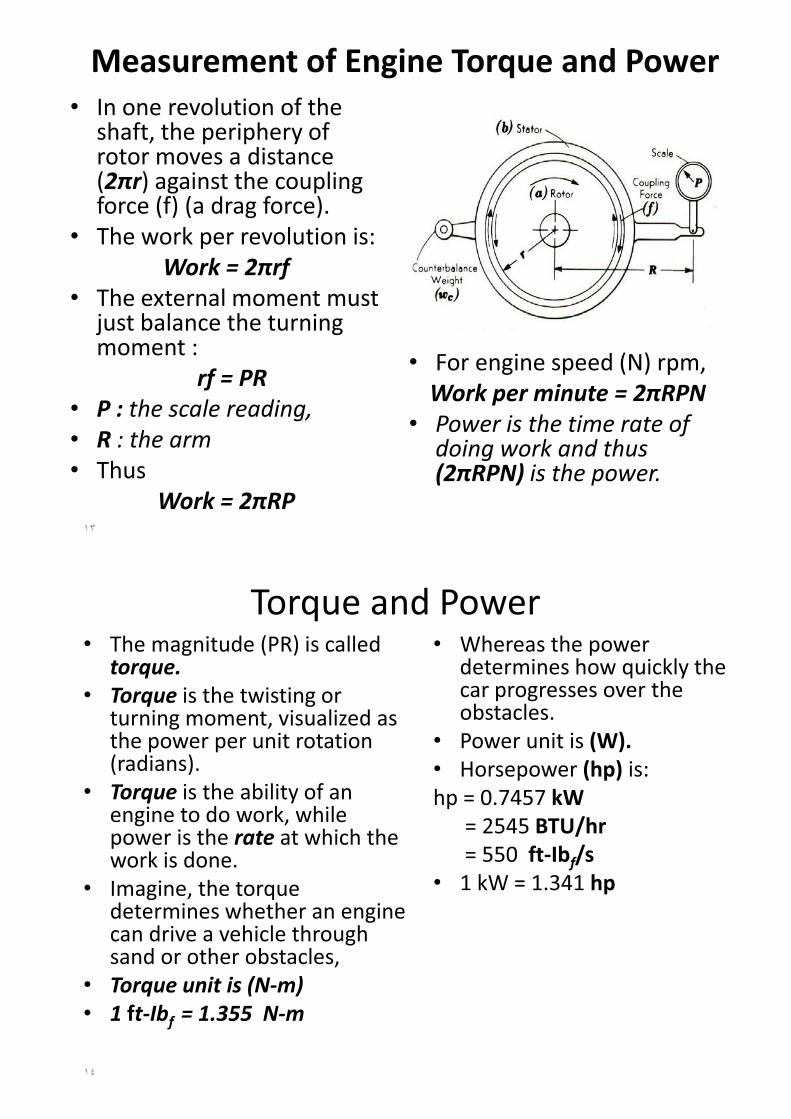
Measurement of Engine Torque and Power• In one revolution of the
shaft, the periphery of rotor moves a distance (2�r) against the coupling force (f) (a drag force).
• The work per revolution is:Work = 2�rf
• The external moment must just balance the turning moment :
rf = PR • P : the scale reading,• R : the arm• Thus
Work = 2�RP
• For engine speed (N) rpm, Work per minute = 2�RPN
• Power is the time rate of doing work and thus (2�RPN) is the power.
��
Torque and Power• The magnitude (PR) is called
torque.• Torque is the twisting or
turning moment, visualized as the power per unit rotation (radians).
• Torque is the ability of an engine to do work, while power is the rate at which the work is done.
• Imagine, the torque determines whether an engine can drive a vehicle through sand or other obstacles,
• Torque unit is (N-m)• 1 ft-Ibf = 1.355 N-m
• Whereas the power determines how quickly the car progresses over the obstacles.
• Power unit is (W).• Horsepower (hp) is:hp = 0.7457 kW
= 2545 BTU/hr= 550 ft-Ibf/s
• 1 kW = 1.341 hp
��

Mean Effective Pressure
��
• The figure shows that pr. in the cylinder is continuously changing during the cycle. A mean effective pr. (mep or P) is defined by:
mep = (work/cycle)/ swept volumeW/cycle = P × Vs
• mep is a good parameter to compare engines for design or output because it is independent of engine size.
Indicated Mean Effective Pressure (Pi)Pi = (a /l)× k (bar)a = area of diagram (mm)l = length of diagram (mm)k = spring constant (bar/mm)• see problems 6 &7 P164 in
Obert’s book.
��
Indicator diagram for a typical 4-stroke cycle SI engine. An indicator diagram plots cylinder pressure as a function of combustion chamber volume over a 720o cycle.
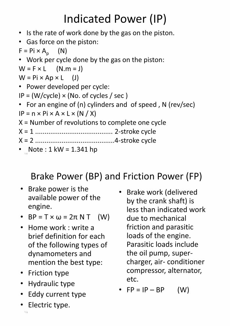
Indicated Power (IP)• Is the rate of work done by the gas on the piston.• Gas force on the piston:F = Pi × Ap (N)• Work per cycle done by the gas on the piston:W = F × L (N.m = J)W = Pi × Ap × L (J)• Power developed per cycle:IP = (W/cycle) × (No. of cycles / sec )• For an engine of (n) cylinders and of speed , N (rev/sec) IP = n × Pi × A × L × (N / X)X = Number of revolutions to complete one cycleX = 1 ......................................... 2-stroke cycleX = 2 ..........................................4-stroke cycle• Note : 1 kW = 1.341 hp
��
e g
Brake Power (BP) and Friction Power (FP)• Brake power is the
available power of the engine.
• BP = T × � = 2� N T (W)• Home work : write a
brief definition for each of the following types of dynamometers and mention the best type:
• Friction type• Hydraulic type• Eddy current type• Electric type.
• Brake work (delivered by the crank shaft) is less than indicated work due to mechanical friction and parasitic loads of the engine. Parasitic loads include the oil pump, super-charger, air- conditioner compressor, alternator, etc.
• FP = IP – BP (W)
�
Air-Fuel Ratio (A/F) and Fuel-Air Ratio (F/A)
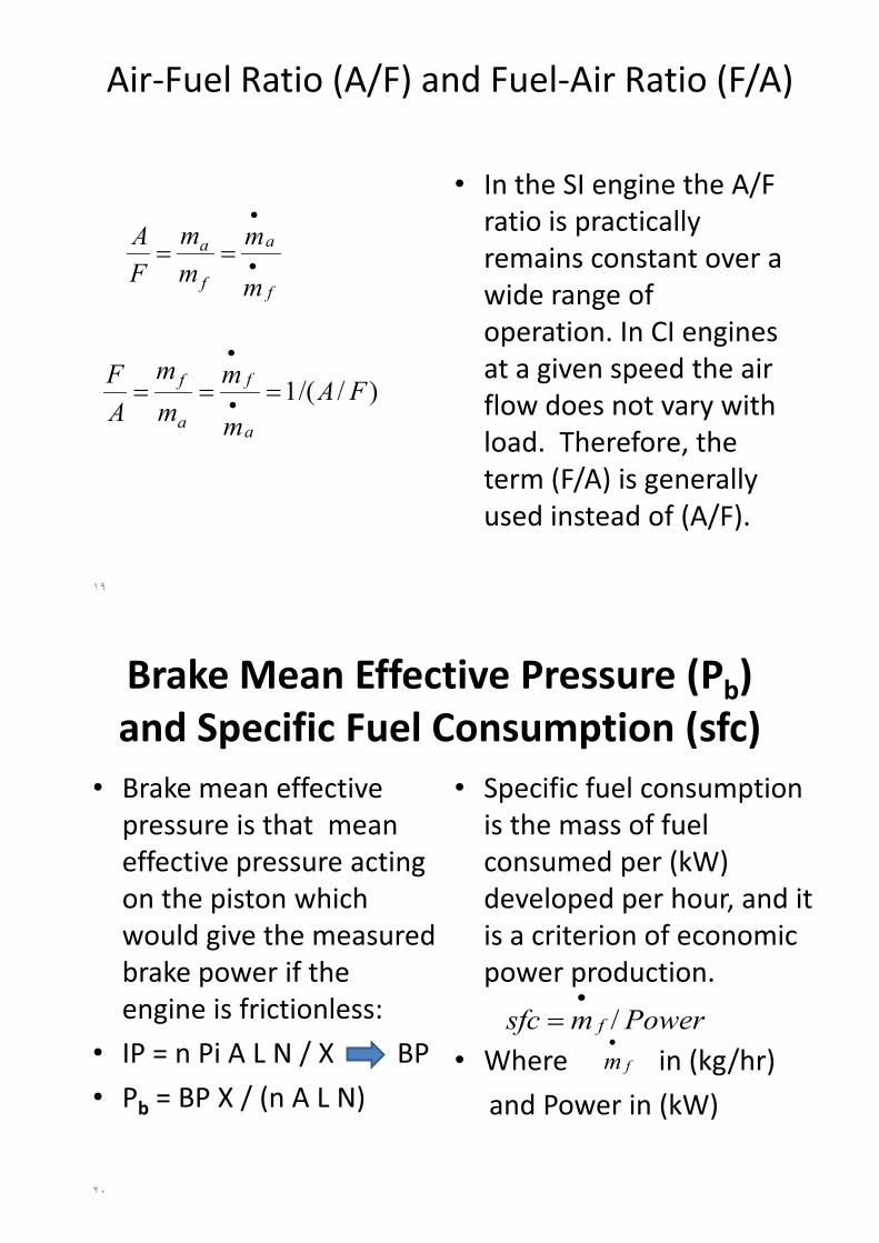
• In the SI engine the A/F ratio is practically remains constant over a wide range of operation. In CI engines at a given speed the air flow does not vary with load. Therefore, the term (F/A) is generally used instead of (A/F).
�
f
a
f
a
m
mmm
FA
�
�
��
)//(1 FAm
mmm
AF
a
f
a
f ��� �
�
Brake Mean Effective Pressure (Pb)and Specific Fuel Consumption (sfc)
• Brake mean effective pressure is that mean effective pressure acting on the piston which would give the measured brake power if the engine is frictionless:
• IP = n Pi A L N / X BP• Pb = BP X / (n A L N)
• Specific fuel consumption is the mass of fuel consumed per (kW) developed per hour, and it is a criterion of economic power production.
• Where in (kg/hr)and Power in (kW)
��
Powermsfc f /�
�fm
�

• Also
•Where • FP : friction power (W)
FP = IP - BP
Engine Mechanical Efficiency• Mechanical efficiency of
engine is
• Where- isfc : indicated specific
fuel consumption
- bsfc: brake specific fuel consumption
��
titbm bsfcisfcIPBP ��� /// ���
IPmisfc f /�
�
BPmbsfc f /�
�
)/(/ FPBPBPIPBPm ����
Engine Efficiencies
��
•The time available for the combustion process of an engine cycle is very brief, and not all fuel molecules may find an oxygen molecule with which to combine. A combustion efficiency ( ) is defined to account for the fraction of fuel which burns. For one engine cycle in one cylinder,the rate heat added is:
Thermal efficiency is defined as
cHVfin QmQ ���
�
int QrOutputPowe�
� /�
• Brake thermal efficiency is
•Indicated thermal efficiency:
•Where- is fuel mass flow rate (kg/s)-QHV is heating value of fuel (J/kg)- is the combustion efficiency• Fuel conversion efficiency is
)/(/ cHVfintb QmBPQBP ����
��
)/(/ cHVfinti QmIPQIP ����
��
c�
c�fm
�
)./(1)/( HVHVff QsfcQmPower ���
�

Volumetric Efficiency• Volumetric efficiency is
the ratio of the actual mass of air sucked by the engine on the intake stroke to the theoretical mass of air that should have been inducted by filling the piston displacement volume with air at atmospheric temp. and pr. .
��
theoaactav mm ,, /��
��
• if �a = constant
• it is also defined as
• Standard atmospheric conditions:-Pa = 101 kPa- Ta = 25 oC
)/./(, XNVm saactav ���
�
theoaactav VV ,, /��
��
)./( saav Vm �� �
XNVV stheoa /, ��
Volumetric Efficiency• Typical values of
volumetric efficiency for an engine at wide-open throttle (WOT) are in the range 75% to 90%, going down to much lower values as the throttle is closed. Restricting air flow into an engine (closing the throttle) is the primary means of power control for a spark ignition engine.
• Notes.1. Supercharging ... �v >=
100%2. Vol. eff. depends on engine
speed (N), compression ratio (CR), valve timing and valve design, cylinder temp. , atmospheric conditions .. etc.
��