ic learning series 2012 - metal cutting processes - turning
TRANSCRIPT
IC LEARNING SERIES
Metal Cutting Processes 1 -
Turning

The Hong Kong Polytechnic UniversityIndustrial Centre
IC LEARNING SERIES
Metal Cutting Processes 1 - TurningSuitable for the following learning modules/subjects offered by the Industrial Centre:
TM0104 Basic MachiningTM0108 Metal Cutting and Fitting PracticeTM1401 Manufacturing ProjectsTM4010 Appreciation of Materials Processing and Basic ElectronicsTM4012 Integrated Training II for PIT HD StudentTM4020 Practical Appreciation of an Intelligent Automation SystemTM4021 Practical Appreciation on How a Transportation Device is Being BuiltCC3214 Appreciation of Manufacturing ProcessesIC2107 Appreciation of Manufacturing Technologies
Last updated: March 2012
Copyright reserved by Industrial Centre, The Hong Kong Polytechnic University

Metal Cutting Processes 1 - Turning
Page 1 IC Professional Training
Objectives:
To identify various types of lathes and their basic construction. To appreciate the industrial applications of lathes. To select appropriate cutters and cutting parameters for turning process. To be familiar with the common turning operations and setup
procedures.
Introduction
This training module is designed to give you 'hands-on' experience through, which you can gain a good appreciation, this well-known type of machine tool. In particular, your attention will be directed to its operational uses and parameters, the general layout of controls, accessories, associated tooling, and the maintenance factors related to lathes.
In order to make the most use of the lathes in a limited time, it is essential that you should get every chance to consolidate what you observe. You must be largely self-motivated and get the desire from yourself in doing this type of work.
It takes a considerable time to become a skilful lathe operator with sufficient hand skills that goes with it. Therefore, you are not expected to be skilful by self-learning on the completion of the module; however, you will gain some experience and appreciate the application of lathe by the practical training.
MMeettaall CCuuttttiinngg PPrroocceesssseess 11 –– TTuurrnniinngg
Metal Cutting Processes 1 - Turning
Page 2 IC Professional Training
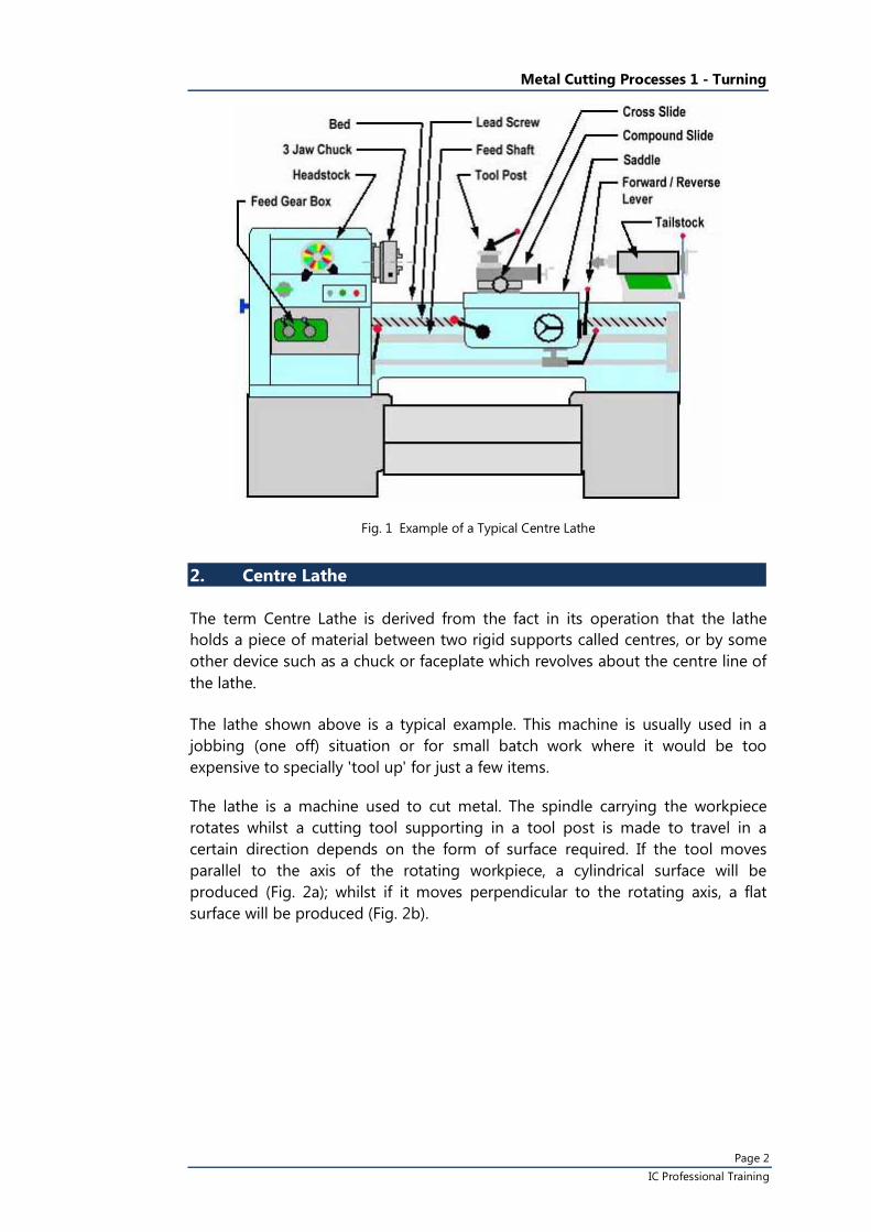
Fig. 1 Example of a Typical Centre Lathe
2. Centre Lathe
The term Centre Lathe is derived from the fact in its operation that the lathe holds a piece of material between two rigid supports called centres, or by some other device such as a chuck or faceplate which revolves about the centre line of the lathe.
The lathe shown above is a typical example. This machine is usually used in a jobbing (one off) situation or for small batch work where it would be too expensive to specially 'tool up' for just a few items.
The lathe is a machine used to cut metal. The spindle carrying the workpiece rotates whilst a cutting tool supporting in a tool post is made to travel in a certain direction depends on the form of surface required. If the tool moves parallel to the axis of the rotating workpiece, a cylindrical surface will be produced (Fig. 2a); whilst if it moves perpendicular to the rotating axis, a flat surface will be produced (Fig. 2b).
Metal Cutting Processes 1 - Turning
Page 3 IC Professional Training
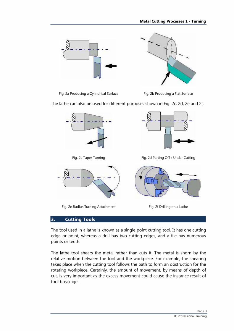
Fig. 2a Producing a Cylindrical Surface Fig. 2b Producing a Flat Surface
The lathe can also be used for different purposes shown in Fig. 2c, 2d, 2e and 2f.
Fig. 2c Taper Turning Fig. 2d Parting Off / Under Cutting
Fig. 2e Radius Turning Attachment Fig. 2f Drilling on a Lathe
3. Cutting Tools
The tool used in a lathe is known as a single point cutting tool. It has one cutting edge or point, whereas a drill has two cutting edges, and a file has numerous points or teeth.
The lathe tool shears the metal rather than cuts it. The metal is shorn by the relative motion between the tool and the workpiece. For example, the shearing takes place when the cutting tool follows the path to form an obstruction for the rotating workpiece. Certainly, the amount of movement, by means of depth of cut, is very important as the excess movement could cause the instance result of tool breakage.
Metal Cutting Processes 1 - Turning
Page 4 IC Professional Training
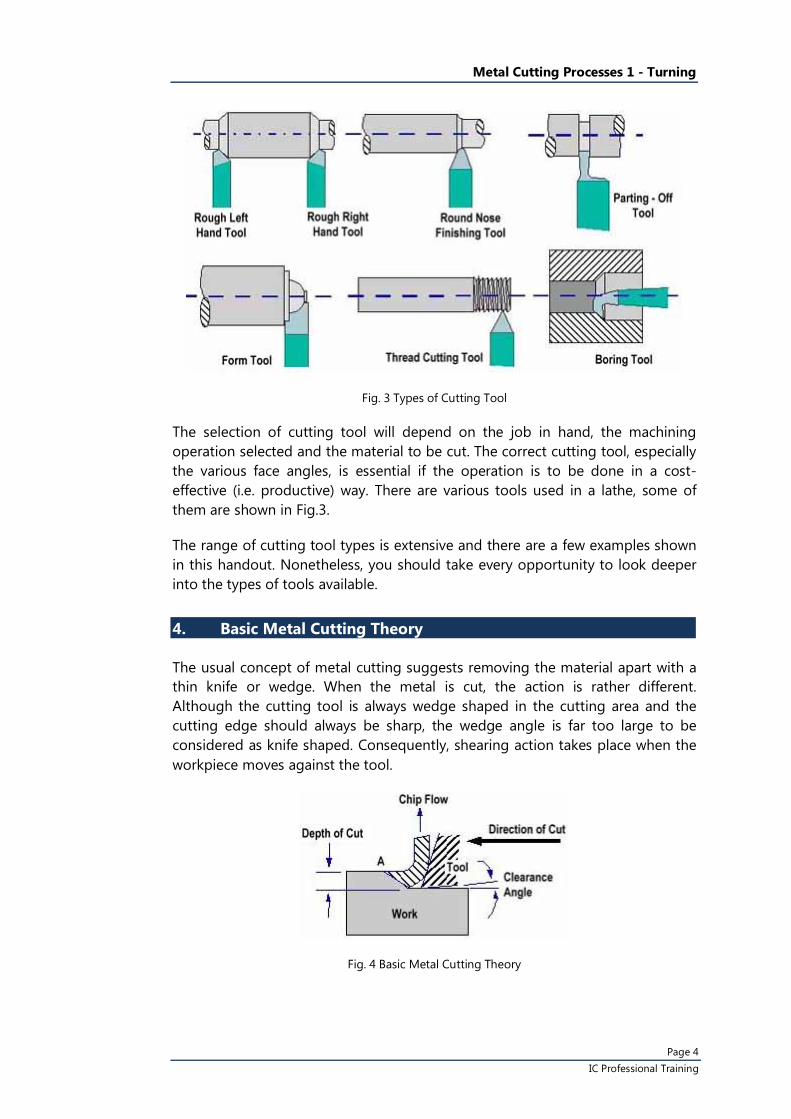
Fig. 3 Types of Cutting Tool
The selection of cutting tool will depend on the job in hand, the machining operation selected and the material to be cut. The correct cutting tool, especially the various face angles, is essential if the operation is to be done in a cost-effective (i.e. productive) way. There are various tools used in a lathe, some of them are shown in Fig.3.
The range of cutting tool types is extensive and there are a few examples shown in this handout. Nonetheless, you should take every opportunity to look deeper into the types of tools available.
4. Basic Metal Cutting Theory
The usual concept of metal cutting suggests removing the material apart with a thin knife or wedge. When the metal is cut, the action is rather different. Although the cutting tool is always wedge shaped in the cutting area and the cutting edge should always be sharp, the wedge angle is far too large to be considered as knife shaped. Consequently, shearing action takes place when the workpiece moves against the tool.
Fig. 4 Basic Metal Cutting Theory
Metal Cutting Processes 1 - Turning
Page 5 IC Professional Training
Fig.4 shows a tool moving against a workpiece. When the metal cutting is in progress, the chip presses heavily on the top face of the tool and continuous shearing takes place across the shear plane AB. Although the Figure shows a tool working in the horizontal plane with the workpiece stationary, the same action takes place with the work piece revolving and the tool stationary.
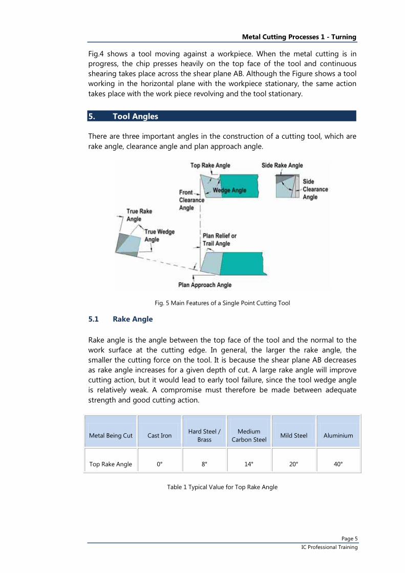
5. Tool Angles
There are three important angles in the construction of a cutting tool, which are rake angle, clearance angle and plan approach angle.
Fig. 5 Main Features of a Single Point Cutting Tool
5.1 Rake Angle
Rake angle is the angle between the top face of the tool and the normal to the work surface at the cutting edge. In general, the larger the rake angle, the smaller the cutting force on the tool. It is because the shear plane AB decreases as rake angle increases for a given depth of cut. A large rake angle will improve cutting action, but it would lead to early tool failure, since the tool wedge angle is relatively weak. A compromise must therefore be made between adequate strength and good cutting action.
Metal Being Cut Cast Iron Hard Steel /
Brass Medium
Carbon Steel Mild Steel Aluminium
Top Rake Angle 0° 8° 14° 20° 40°
Table 1 Typical Value for Top Rake Angle
Metal Cutting Processes 1 - Turning
Page 6 IC Professional Training
5.2 Clearance Angle
Clearance angle is the angle between the flank or front face of the tool and a tangent to the work surface originating at the cutting edge. All cutting tools must have clearance to allow cutting to take place. Clearance should be kept to a minimum, as excessive clearance angle will not improve cutting efficiency and it will merely weaken the tool. Typical value for front clearance angle is 6° in external turning.
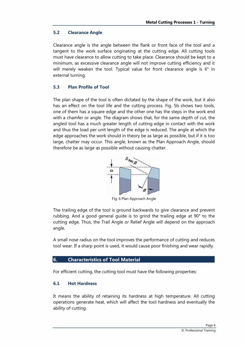
5.3 Plan Profile of Tool
The plan shape of the tool is often dictated by the shape of the work, but it also has an effect on the tool life and the cutting process. Fig. 5b shows two tools, one of them has a square edge and the other one has the steps in the work end with a chamfer or angle. The diagram shows that, for the same depth of cut, the angled tool has a much greater length of cutting edge in contact with the work and thus the load per unit length of the edge is reduced. The angle at which the edge approaches the work should in theory be as large as possible, but if it is too large, chatter may occur. This angle, known as the Plan Approach Angle, should therefore be as large as possible without causing chatter.
Fig. 6 Plan Approach Angle
The trailing edge of the tool is ground backwards to give clearance and prevent rubbing. And a good general guide is to grind the trailing edge at 90° to the cutting edge. Thus, the Trail Angle or Relief Angle will depend on the approach angle.
A small nose radius on the tool improves the performance of cutting and reduces tool wear. If a sharp point is used, it would cause poor finishing and wear rapidly.
6. Characteristics of Tool Material
For efficient cutting, the cutting tool must have the following properties:
6.1 Hot Hardness
It means the ability of retaining its hardness at high temperature. All cutting operations generate heat, which will affect the tool hardness and eventually the ability of cutting.
Metal Cutting Processes 1 - Turning
Page 7 IC Professional Training
6.2 Strength and Resistance to Shock
At the start of a cut, the first bite of the tool into the work results in considerable shock loading on the tool. It must obviously be strong enough to withstand it.
6.3 Low Coefficient of Friction
Heat is produced when the tool is rubbing against the workpiece and the chip is rubbing on the top face of the cutting tool produce heat. As a result, it must be kept to a minimum.
7. Tool Materials in Common Use
7.1 High Carbon Steel
It contains 1 - 1.4% carbon with some addition of chromium and tungsten to improve wear resistance. The steel begins to lose its hardness at about 250° C, and it is not favoured for modern machining operations where high speeds and heavy cuts are usually employed.
7.2 High Speed Steel (HSS)
Steel, which has a hot hardness value of about 600° C, possesses good strength and shock resistant properties. It is commonly used for single point lathe cutting tools and multi point cutting tools such as drills, reamers and milling cutters.
7.3 Cemented Carbides
An extremely hard material made of tungsten powder. Carbide tools are usually used in the form of brazed or clamped tips. High cutting speeds may be used and the materials which are difficult to cut with HSS may be readily machined using carbide tipped tool.
8. Tool Life
As a general rule the relationship between the tool life and cutting speed is
VTn = C
where; V = cutting speed in m/min T = tool life in min C = a constant
For high-speed steel tools, the value of C ranges is from 0.14 to 0.1 and for carbide tools the value would be 0.2.
Metal Cutting Processes 1 - Turning
Page 8 IC Professional Training
9. Chip Formation and Chip Breaker
The type of chip produced depends on the material being machined and the cutting conditions at the time. These conditions include the type of tool, used tool, rate of cutting condition of the machine and the use or absence of a cutting fluid.
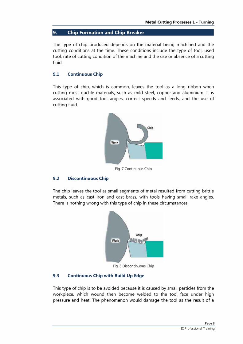
9.1 Continuous Chip
This type of chip, which is common, leaves the tool as a long ribbon when cutting most ductile materials, such as mild steel, copper and aluminium. It is associated with good tool angles, correct speeds and feeds, and the use of cutting fluid.
Fig. 7 Continuous Chip
9.2 Discontinuous Chip
The chip leaves the tool as small segments of metal resulted from cutting brittle metals, such as cast iron and cast brass, with tools having small rake angles. There is nothing wrong with this type of chip in these circumstances.
Fig. 8 Discontinuous Chip
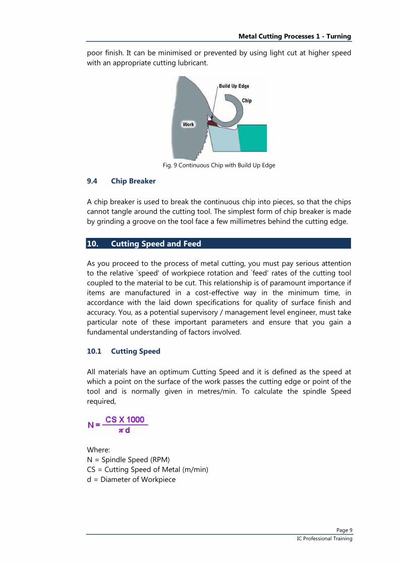
9.3 Continuous Chip with Build Up Edge
This type of chip is to be avoided because it is caused by small particles from the workpiece, which wound then become welded to the tool face under high pressure and heat. The phenomenon would damage the tool as the result of a
Metal Cutting Processes 1 - Turning
Page 9 IC Professional Training
poor finish. It can be minimised or prevented by using light cut at higher speed with an appropriate cutting lubricant.
Fig. 9 Continuous Chip with Build Up Edge
9.4 Chip Breaker
A chip breaker is used to break the continuous chip into pieces, so that the chips cannot tangle around the cutting tool. The simplest form of chip breaker is made by grinding a groove on the tool face a few millimetres behind the cutting edge.
10. Cutting Speed and Feed
As you proceed to the process of metal cutting, you must pay serious attention to the relative `speed' of workpiece rotation and `feed' rates of the cutting tool coupled to the material to be cut. This relationship is of paramount importance if items are manufactured in a cost-effective way in the minimum time, in accordance with the laid down specifications for quality of surface finish and accuracy. You, as a potential supervisory / management level engineer, must take particular note of these important parameters and ensure that you gain a fundamental understanding of factors involved.
10.1 Cutting Speed
All materials have an optimum Cutting Speed and it is defined as the speed at which a point on the surface of the work passes the cutting edge or point of the tool and is normally given in metres/min. To calculate the spindle Speed required,
Where: N = Spindle Speed (RPM) CS = Cutting Speed of Metal (m/min) d = Diameter of Workpiece
Metal Cutting Processes 1 - Turning
Page 10 IC Professional Training
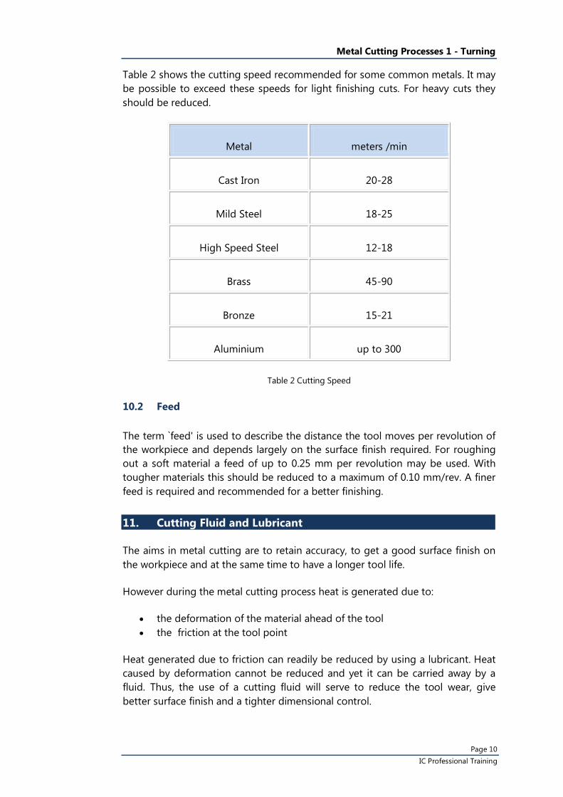
Table 2 shows the cutting speed recommended for some common metals. It may be possible to exceed these speeds for light finishing cuts. For heavy cuts they should be reduced.
Metal meters /min
Cast Iron 20-28
Mild Steel 18-25
High Speed Steel 12-18
Brass 45-90
Bronze 15-21
Aluminium up to 300
Table 2 Cutting Speed
10.2 Feed
The term `feed' is used to describe the distance the tool moves per revolution of the workpiece and depends largely on the surface finish required. For roughing out a soft material a feed of up to 0.25 mm per revolution may be used. With tougher materials this should be reduced to a maximum of 0.10 mm/rev. A finer feed is required and recommended for a better finishing.
11. Cutting Fluid and Lubricant
The aims in metal cutting are to retain accuracy, to get a good surface finish on the workpiece and at the same time to have a longer tool life.
However during the metal cutting process heat is generated due to:
• the deformation of the material ahead of the tool • the friction at the tool point
Heat generated due to friction can readily be reduced by using a lubricant. Heat caused by deformation cannot be reduced and yet it can be carried away by a fluid. Thus, the use of a cutting fluid will serve to reduce the tool wear, give better surface finish and a tighter dimensional control.
Metal Cutting Processes 1 - Turning
Page 11 IC Professional Training
The proper selection, mixing and application of cutting fluids is, however, often misunderstood and frequently neglected in machining practice. In order that the cutting fluid performs its functions properly, it is necessary to ensure that the cutting fluid would be applied directly to the cutting zone, so that it can form a film at the sliding surfaces of the tool.
11.1 Cutting Fluids in Common Use
Water
It has a high specific heat but is poor in lubrication and also encourages rusting. It is used as a cooling agent during tool grinding.
Soluble Oils
Oil will not dissolve in water but can be made to form an intimate mixture or emulsion by adding emulsifying agents. The oil is then suspended in the water in the form of tiny droplets. These fluids have average lubricating abilities and good cooling properties. Soluble oils are suitable for light cutting operations on general purpose machines where high rates of metal removal are often not of prime importance. There are many forms of soluble oil in the market and the suppliers’ instruction should be followed regarding the proportions of the `mix'.
Mineral Oils
They are used for heavier cutting operations because of their good lubricating properties. They are commonly found in production machines where high rates of metal removal are employed. Mineral oils are very suitable for machining steels but should not be used on copper or its alloys since it has a corrosive effect.
Vegetable Oils
They are good lubricants but are of little used since they are liable to decompose and smell badly.
Metal Cutting Processes 1 - Turning
Page 12 IC Professional Training
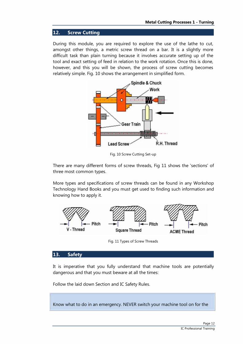
12. Screw Cutting
During this module, you are required to explore the use of the lathe to cut, amongst other things, a metric screw thread on a bar. It is a slightly more difficult task than plain turning because it involves accurate setting up of the tool and exact setting of feed in relation to the work rotation. Once this is done, however, and this you will be shown, the process of screw cutting becomes relatively simple. Fig. 10 shows the arrangement in simplified form.
Fig. 10 Screw Cutting Set-up
There are many different forms of screw threads, Fig 11 shows the 'sections' of three most common types.
More types and specifications of screw threads can be found in any Workshop Technology Hand Books and you must get used to finding such information and knowing how to apply it.
Fig. 11 Types of Screw Threads
13. Safety
It is imperative that you fully understand that machine tools are potentially dangerous and that you must beware at all the times:
Follow the laid down Section and IC Safety Rules.
Know what to do in an emergency. NEVER switch your machine tool on for the
Metal Cutting Processes 1 - Turning
Page 13 IC Professional Training
first time until given permission by your Staff Member to do so. At varying stages in your programme if the Staff Member is satisfied with your operational knowledge you will be given permission to proceed on specific steps unsupervised. This is a measure of the Staff Member confidence in you and you should be pleased that you are so trusted and live up to that trust by taking all reasonable safety precautions.
Well-qualified and enthusiastic IC staffs are ready and willing to help you. And it is up to you to make most use of their willingness to transfer their technical knowledge and their experience to you.
14. Conclusion
Lathes are normally robust in construction and they will, with good care, last for many years. It is usual for instance to see good lathes still in uses that are 50 years old. To ensure good, accurate, trouble free use, it is necessary that the correct maintenance routines are regularly carried out and that important surfaces such as slide-ways are kept well protected, so as to reduce wear and thus maintain good accuracy. This aspect of 'good husbandry' should be of interested to you and you will be expected to demonstrate an understanding of it. In this respect, the types of maintenance routine carried out, the design and accessibility of the maintenance system, and the lubricants used, are all factors that require your attention.
Recommended Reference Book
Workshop Technology Parts 1, 2 and 3 Author : WAJ Chapman Publisher : London: Edward Arnold, 1972
All About Machine Tools Author : Heinrich Gerling Publisher : Wiley Eastern Limited, 1965
Manufacturing Technology
Author : G Bram & C Downs Publisher : London: MacMillan, 1975