ic-dc-ts915 - motorway systems - motorway network
TRANSCRIPT
Technical Direction – TD 00001:2022
© State of NSW through Transport for NSW 2022 Page 1 of 3
For queries regarding this document [email protected]
www.transport.nsw.gov.au
Technical Direction – TD 00001:2022 Issue date: 28 January 2022
Effective date: 28 January 2022
Title: Amendment to optical fibre cable for roads applications
This technical direction is issued by the Asset Management Branch (AMB) as an update to
IC-DC-TS915.
The updates include amendments to refer to TS 06212 for requirements related to optical fibre
cables and to further specify cable design and construction elements.
1 Amendment to IC-DC-TS915 The sections in IC-DC-TS915 Motorway Systems - Motorway Network Communications System
shall be amended as follows:
Section 3.5.1 Optical Fibre Cable Delete dot points (a) to (g).
Add the following new paragraphs:
Optical fibre cable shall comply with TS 06212.
The cable sheath shall be legibly and durably marked in one metre intervals with the cable
identification information as defined in TS 06212, except that “TRANSPORT MANAGEMENT
CENTRE 131 700” is in place of the registered entity name of the asset steward for operate and
maintain.
Annexure TS915/F Delete the content of annexure and replace with the following content:

Technical Direction – TD 00001:2022
© State of NSW through Transport for NSW 2022 Page 2 of 3
Figure TS915/F.1 shows the reference model for optical fibre cable as a cross-section depicting
common cable design and construction elements.
Figure TS915/F.1 – Optical fibre cable reference model
Table TS915/F.1 and Table TS915/F.2 specify the required cable design and construction
elements.
Table TS915/F.1 – Backbone cable element specification
Element Requirement Specification
Central strength member Yes Glass fibre reinforced plastic.
Optical fibres Yes OS2.
Buffer tubes Yes Gel filled.
Water blocking layer Yes
Inner sheath Yes
Insect resistant layer Yes Polyamide as defined in TS 06212.
Rodent resistant layer Yes Glass fibre reinforced plastic as defined in TS 06212.
Outer sheath Yes Yellow in colour. Where in tunnels, RHE as defined in TS 06212.
Outer jacket No
8. Outer sheath
7. Rodent resistant layer
6. Insect resistant layer
5. Inner sheath
4. Water blocking layer
1. Central strength member
3. Buffer tubes
2. Optical fibres
9. Outer jacket

Technical Direction – TD 00001:2022
© State of NSW through Transport for NSW 2022 Page 3 of 3
Table TS915/F.2 – Local segments cable element specification
Element Requirement Specification
Central strength member Yes Glass fibre reinforced plastic.
Optical fibres Yes OS2.
Buffer tubes Yes Gel filled.
Water blocking layer Yes
Inner sheath Yes
Insect resistant layer Yes Polyamide as defined in TS 06212.
Rodent resistant layer No
Outer sheath Yes Yellow in colour. Where in tunnels, RHE as defined in TS 06212.
Outer jacket No
Optical fibre cables shall be offered in the following configurations as defined in
Table TS915/F.3.
Table TS915/F.3 – Cable configurations for motorway network communications system
Customer cabling subsystem
Cable application
Fire resistance Reduced hazardous effects
Number of fibres
Campus backbone cable
Outdoor No No 12, 48, 72
Campus backbone cable
Outdoor No Yes 12, 48, 72
Authorisation:
Approved by Director Telecom Engineering, Asset Management Branch

Edition 1 / Revision 2 TRANSPORT FOR NSW June 2020
TRANSPORT FOR NSW (TfNSW)
TfNSW SPECIFICATION D&C TS915
MOTORWAY SYSTEMS - MOTORWAY NETWORK COMMUNICATIONS SYSTEM
NOTICE
This document is a Transport for NSW D&C Specification. It has been developed for use with Design & Construct roadworks and bridgeworks contracts let by Transport for NSW. It is not suitable for any other purpose and must not be used for any other purpose or in any other context.
Copyright in this document belongs to Transport for NSW.
REVISION REGISTER
Ed/Rev Number
Clause Number Description of Revision Authorised
By Date
Ed 1/Rev 0 First issue as “OMCS Requirements – Motorway Network Communications System”, based on non-D&C Specification TS915 Ed 1/Rev 1.
A/GM, CS (J Staugas)
14.06.17
Global Specification reorganised and reworded to improve clarity and consistency of terminology.
Major changes with network topology clarification, network latency, POE and cableway requirements.
Updates to Annexures with new figures and tables.
Ed 1/Rev 1 Spec title changed. DCS 10.06.20
Clauses reworded to improve clarity.
1.2 Related specs and figure updated.
1.4.1 Definitions updated.
2.2.5 New sub-clause titled “IP Addressing Plan” inserted. Subsequent sub-clause renumbered.
2.3.1 (b) Requirement for GUI to be accessible via workstations added.
2.3.2 (b) “TMCS or PMCS” and “OMCS” changed to “OMCS (TMCS/PMCS)”.
2.6.1 (a) (ii) “operator interface workstations” changed to “Motorway operator workstations”
2.8 New clause on “MNCS Testing and Commissioning”.

ii
Ed/Rev Number
Clause Number Description of Revision Authorised
By Date
Ed 1/Rev 1 3.2 IEEE reference updated. (cont’d) 3.5.1 (c) Optical fibre cable to be suitable for
environment of installation instead of “outdoor ground use” only.
Annex D Updated.
Ed 1/Rev 2 Global References to “Roads and Maritime Services” or “RMS” changed to “Transport for NSW” or “TfNSW” respectively.
DCS 22.06.20
References to “RMS Representative” changed to “Principal”.

Edition 1 / Revision 2 TRANSPORT FOR NSW June 2020
SPECIFICATION D&C TS915
MOTORWAY SYSTEMS - MOTORWAY NETWORK
COMMUNICATIONS SYSTEM Copyright – Transport for NSW
IC-DC-TS915
VERSION FOR: DATE:


Motorway Systems - Motorway Network Communications System D&C TS915
Ed 1 / Rev 2 i
CONTENTS
CLAUSE PAGE
FOREWORD ............................................................................................................................................... II TfNSW Copyright and Use of this Document ............................................................................... ii Base Specification .......................................................................................................................... ii
1 GENERAL ........................................................................................................................................ 1 1.1 Scope .............................................................................................................................. 1 1.2 Related Specifications .................................................................................................... 1 1.3 Structure of the Specification ......................................................................................... 2 1.4 Definitions and Acronyms .............................................................................................. 3
2 MOTORWAY NETWORK COMMUNICATIONS SYSTEM .................................................................... 4 2.1 General Requirements .................................................................................................... 4 2.2 Network Architecture ..................................................................................................... 5 2.3 Network Management System........................................................................................ 8 2.4 Network Security ............................................................................................................ 9 2.5 Network Protocols ........................................................................................................ 11 2.6 Network Devices and Equipment ................................................................................. 11 2.7 MNCS Availability ....................................................................................................... 12 2.8 MNCS Testing and Commissioning ............................................................................. 12
3 MNCS INFRASTRUCTURE REQUIREMENTS .................................................................................. 12 3.1 Power Supply................................................................................................................ 12 3.2 Power over Ethernet (PoE) ........................................................................................... 12 3.3 Separation of ETC System ........................................................................................... 13 3.4 Cableway ...................................................................................................................... 13 3.5 Optical Fibre Cabling ................................................................................................... 15 3.6 Cable Installation .......................................................................................................... 16 3.7 Cable Termination ........................................................................................................ 16 3.8 Outdoor Equipment ...................................................................................................... 17 3.9 Third Party Network for Connection of Remote Roadside Devices ............................ 17 3.10 Testing and As-built Details ......................................................................................... 17
4 TFNSW TRAFFIC DATA NETWORK INFRASTRUCTURE ................................................................ 18 4.1 General ......................................................................................................................... 18 4.2 Dedicated TfNSW Equipment Cabinet ........................................................................ 18 4.3 Dedicated TfNSW Conduits ......................................................................................... 19 4.4 Dedicated TfNSW Optical Fibre Cabling .................................................................... 20 4.5 MNCS - TfNSW Traffic Data Network Interface ........................................................ 21 4.6 Testing and As-built Details ......................................................................................... 21
ANNEXURES TS915/A AND TS915/B – (NOT USED) .............................................................................. 22
ANNEXURE TS915/C – SCHEDULES OF HOLD POINTS, WITNESS POINTS AND IDENTIFIED RECORDS... 22 C1 Schedule of Hold Points and Witness Points ................................................................ 22 C2 Schedule of Identified Records ..................................................................................... 22
ANNEXURE TS915/D – PLANNING DOCUMENTS ................................................................................... 23
ANNEXURE TS915/E - ILLUSTRATION OF REQUIREMENTS FOR DEDICATED TFNSW CONDUIT IN LOCAL ROAD CABLEWAY ............................................................................................................ 24

D&C TS915 Motorway Systems - Motorway Network Communications System
ii Ed 1 / Rev 2
ANNEXURE TS915/F – TFNSW SMOF CABLE CHARACTERISTICS ....................................................... 25
ANNEXURES TS915/G TO TS915/L – (NOT USED) ................................................................................. 25
ANNEXURE TS915/M – REFERENCED DOCUMENTS ............................................................................... 26
LAST PAGE OF THIS DOCUMENT IS .......................................................................................................... 26
FOREWORD
TFNSW COPYRIGHT AND USE OF THIS DOCUMENT
Copyright in this document belongs to Transport for NSW.
When this document forms part of a deed
This document should be read with all the documents forming the Project Deed.
When this document does not form part of a deed
This copy is not a controlled document. Observe the Notice that appears on the first page of the copy controlled by TfNSW. A full copy of the latest version of the document is available on the TfNSW Internet website: http://www.rms.nsw.gov.au/business-industry/partners-suppliers/specifications/index.html
BASE SPECIFICATION
This document has been revised from Specification TfNSW D&C TS915 Edition 1 Revision 1.
All revisions to the previous version (other than minor editorial and project specific changes) are indicated by a vertical line in the margin as shown here, except when it is a new edition and the text has been extensively rewritten.

(TfNSW COPYRIGHT AND USE OF THIS DOCUMENT - Refer to the Foreword after the Table of Contents)
Ed 1 / Rev 1
TfNSW SPECIFICATION D&C TS915
MOTORWAY SYSTEMS - MOTORWAY NETWORK COMMUNICATIONS SYSTEM
1 GENERAL
1.1 SCOPE
This Specification sets out the requirements for the design and construction of the Motorway Network Communications System (MNCS), which carries the data, voice and video image communications from devices and equipment at locations along the Motorway to the Motorway Control Centre (MCC), and vice versa.
It also includes the requirements for the design and construction of communications infrastructure for the exclusive use of TfNSW as part of the TfNSW Traffic Data Network.
The MNCS must be suitable for the full range of Motorway operational requirements, including emergency situations.
1.2 RELATED SPECIFICATIONS
This Specification is a Level 2 document which forms part of the suite of TfNSW specification documents for Motorway Systems (see figure below). Other documents within the suite are:
Level 1
• D&C TS901 “Motorway Systems Overview and General Requirements”;
Level 2
• D&C TS902 “Systems Engineering Processes”;
• D&C TS911 “Motorway Systems - Motorway Control Centre”;
• D&C TS912 “Motorway Systems - Traffic Management and Control System”;
• D&C TS913 “Motorway Systems - Plant Management and Control System”;
• D&C TS914 “Motorway Systems - Electrical Power Supply and Distribution System”;
• D&C TS916 “Motorway Systems - Electronic Toll Collection System”;
• D&C TS917 “Motorway Systems - C2C Interface for Motorways”;
• D&C TS918 “Motorway Systems - Road Tunnel and Underpass Lighting”.
(TfNSW COPYRIGHT AND USE OF THIS DOCUMENT - Refer to the Foreword after the Table of Contents) D&C TS915 Motorway Systems - Motorway Network Communications System
2 Ed 1 / Rev 2
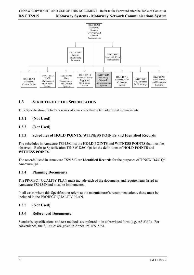
1.3 STRUCTURE OF THE SPECIFICATION
This Specification includes a series of annexures that detail additional requirements.
1.3.1 (Not Used)
1.3.2 (Not Used)
1.3.3 Schedules of HOLD POINTS, WITNESS POINTS and Identified Records
The schedules in Annexure TS915/C list the HOLD POINTS and WITNESS POINTS that must be observed. Refer to Specification TfNSW D&C Q6 for the definitions of HOLD POINTS and WITNESS POINTS.
The records listed in Annexure TS915/C are Identified Records for the purposes of TfNSW D&C Q6 Annexure Q/E.
1.3.4 Planning Documents
The PROJECT QUALITY PLAN must include each of the documents and requirements listed in Annexure TS915/D and must be implemented.
In all cases where this Specification refers to the manufacturer’s recommendations, these must be included in the PROJECT QUALITY PLAN.
1.3.5 (Not Used)
1.3.6 Referenced Documents
Standards, specifications and test methods are referred to in abbreviated form (e.g. AS 2350). For convenience, the full titles are given in Annexure TS915/M.
D&C TS915 Motorway Network
Communications System
D&C TS918 Road Tunnel
and Underpass Lighting
D&C TS917 C2C Interface for Motorways
D&C TS916 Electronic Toll
Collection System
D&C TS914 Electrical Power
Supply and Distribution
System
D&C TS913 Plant
Management and Control
System
D&C TS912 Traffic
Management and Control
System
D&C TS911 Motorway
Control Centre
D&C TS 902 Systems
Engineering Processes
D&C TS903 Asset Life Cycle
Management
D&C TS901 Motorway Systems
Overview and General
Requirements
(TfNSW COPYRIGHT AND USE OF THIS DOCUMENT - Refer to the Foreword after the Table of Contents) Motorway Systems - Motorway Network Communications System D&C TS915
Ed 1 / Rev 3
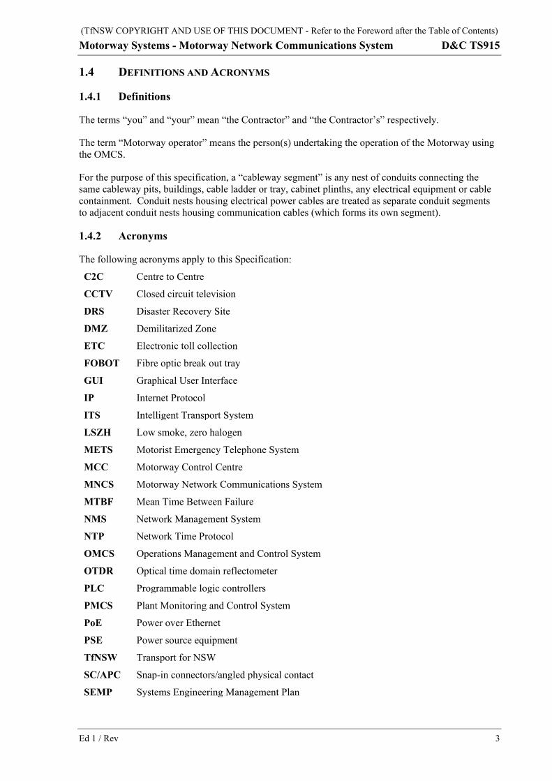
1.4 DEFINITIONS AND ACRONYMS
1.4.1 Definitions
The terms “you” and “your” mean “the Contractor” and “the Contractor’s” respectively.
The term “Motorway operator” means the person(s) undertaking the operation of the Motorway using the OMCS.
For the purpose of this specification, a “cableway segment” is any nest of conduits connecting the same cableway pits, buildings, cable ladder or tray, cabinet plinths, any electrical equipment or cable containment. Conduit nests housing electrical power cables are treated as separate conduit segments to adjacent conduit nests housing communication cables (which forms its own segment).
1.4.2 Acronyms
The following acronyms apply to this Specification:
C2C Centre to Centre
CCTV Closed circuit television
DRS Disaster Recovery Site
DMZ Demilitarized Zone
ETC Electronic toll collection
FOBOT Fibre optic break out tray
GUI Graphical User Interface
IP Internet Protocol
ITS Intelligent Transport System
LSZH Low smoke, zero halogen
METS Motorist Emergency Telephone System
MCC Motorway Control Centre
MNCS Motorway Network Communications System
MTBF Mean Time Between Failure
NMS Network Management System
NTP Network Time Protocol
OMCS Operations Management and Control System
OTDR Optical time domain reflectometer
PLC Programmable logic controllers
PMCS Plant Monitoring and Control System
PoE Power over Ethernet
PSE Power source equipment
TfNSW Transport for NSW
SC/APC Snap-in connectors/angled physical contact
SEMP Systems Engineering Management Plan

(TfNSW COPYRIGHT AND USE OF THIS DOCUMENT - Refer to the Foreword after the Table of Contents) D&C TS915 Motorway Systems - Motorway Network Communications System
4 Ed 1 / Rev 2
SMOF Single mode optical fibre
SWTC Project Deed Scope of Works and Technical Criteria
TMC Transport Management Centre
TMCS Traffic Management and Control System
VMS Variable message sign(s)
VLAN Virtual Local Area Network
WAN Wide Area Network
2 MOTORWAY NETWORK COMMUNICATIONS SYSTEM
2.1 GENERAL REQUIREMENTS
(a) The Contractor is responsible for the design and construction of the Motorway Network Communications System (MNCS), to the requirements stated in Clauses 2 and 3.
2.1.1 Services To Be Provided
(a) The MNCS must provide the following communication infrastructure services:
(i) data communications between the OMCS computing infrastructure at the MCC and the roadside and tunnel devices;
(ii) data communications with the MCC and the Disaster Recovery Site (DRS);
(iii) data communications between the OMCS computing infrastructure at the DRS and the roadside and tunnel devices;
(iv) voice communications from Motorist Emergency Telephone System (METS) and Fire Emergency Telephone System to the MCC and DRS;
(v) Motorway closed circuit television (CCTV) camera image and control data communications between the Motorway CCTV sites, the MCC, and DRS;
(vi) data communications between the MCC, DRS and TfNSW/Transport Management Centre (TMC) Wide Area Network (WAN);
(vii) data communications for the Motorway Electronic Toll Collection (ETC) System.
2.1.2 Adequate Capacity
(a) The MNCS must provide adequate communications capacity to support the OMCS operation under all conditions of communication load.
2.1.3 Compatibility
(a) The MNCS must be compatible with existing computer systems, equipment and Intelligent Transport System (ITS) devices and signs used in the TfNSW OMCS for adjoining tunnels, roadways and motorways.
2.1.4 Weather Conditions
(a) The MNCS must be capable of withstanding the adverse effects of all weather conditions likely to be encountered on the Motorway or tunnel.

(TfNSW COPYRIGHT AND USE OF THIS DOCUMENT - Refer to the Foreword after the Table of Contents) Motorway Systems - Motorway Network Communications System D&C TS915
Ed 1 / Rev 5
2.2 NETWORK ARCHITECTURE
2.2.1 General
(a) The MNCS must be a resilient and reliable system, designed to be fault tolerant and fail-safe with layers of redundancy, so that any singular failure of the MNCS components will not adversely impact the operation of the OMCS.
(b) The MNCS design must be scalable and flexible. It must provide high availability, fault tolerant network access by using redundant devices within each layer to provide device level redundancy and dual forwarding paths.
(c) The MNCS architecture must prevent cascading failures as the result of a fault. The failure of any component or module of the MNCS must not cause failure of any other component or module of the MNCS or OMCS.
(d) The operation of the MNCS must not be degraded as a result of a single communications cable failure or breakage event.
2.2.2 Network Topology
(a) The MNCS network topology must be dual (fibre) ring, as shown conceptually in Figure TS915.1.
(b) The MNCS network topology must be resilient to any single cable break at any point within the physical infrastructure.

(TfNSW COPYRIGHT AND USE OF THIS DOCUMENT - Refer to the Foreword after the Table of Contents) D&C TS915 Motorway Systems - Motorway Network Communications System
6 Ed 1 / Rev 2
Core-Distribution Connectivity
Distribution-Access Connectivity
Figure TS915.1 - Dual Ring Network Topology
(c) The MNCS design must prevent data flooding due to malfunction of network elements, particularly where protocols, such as spanning tree, are used.
(d) Subnets and/or virtual Local Area Networks (VLANs) must be used to functionally group devices e.g. traffic control devices, traffic data, Motorist Emergency Telephone System (METS) and CCTV.
Traffic Management and Control System (TMCS) and Plant Management and Control System (PMCS) subnets/VLANs must be set up separately on the MNCS.
(e) CCTV and traffic monitoring video services from the Motorway or tunnel must be separated from other MNCS services to prevent bandwidth degradation.
(f) Network edge firewalls must be provided at both the MCC and DRS.
Ring 1
Dist Dist
Acc Dev Acc
Acc Dev Acc
Dis
tribu
tion
Nod
e 1
To Core
Dist Dist
Acc Dev Acc
Acc Dev Acc
Dis
tribu
tion
Nod
e 2
To Core
Ring 2
Cor
e Sw
itch
Cor
e Sw
itch
Ring 1 - Primary
Backbone
Dist Dist Dist Dist Dist
Ring 2 - Secondary Backbone
Key Dist: Distribution Switch Acc: Access Switch Dev: Device
Note: For further details on Core, Distribution and Access layers, refer Clause 2.2.3.

(TfNSW COPYRIGHT AND USE OF THIS DOCUMENT - Refer to the Foreword after the Table of Contents) Motorway Systems - Motorway Network Communications System D&C TS915
Ed 1 / Rev 7
2.2.3 Network Functional Layers
(a) The MNCS design must be based on a modular and hierarchical design which groups the network into different functional layers with Layer 3 routed topology.
ACCESS(End users and Roadside Devices Connectivity)
DISTRIBUTION(Policy based Connectivity)
CORE (High Switching Capacity)
Figure TS915.2 – Network Functional Layers
(b) The Network functional layers in the MNCS design comprise the following:
2.2.3.1 Core Layer
(a) This is the backbone layer, with high speed switching and the ability to move larger quantities of data. It handles the requests from lower network layers and provides services to other layers.
(b) The core layer must be reliable and fault tolerant, with redundant hardware. All hardware must be fitted with dual redundant power supplies, as a minimum.
(c) The core layer must implement multiple forwarding paths to ensure redundancy.
(d) The combination of static and dynamic routing protocols may be used to provide routing. The MNCS design must describe the details of the routing protocols.
2.2.3.2 Distribution or Aggregation Layer
(a) This is the isolation point between the network’s access layer and the core layer. It is used for policy base services and controls the access of data to the core layer and provides the redundancy to access devices. This is achieved by VLAN, including VLAN definitions, VLAN routing, media transitions where there are changes to the Maximum Transmission Unit or frame format, and security access control lists.
(b) The MNCS architecture must adopt logical separation of the network into VLANs for roadside devices and CCTV. This reduces network congestion overheads by ensuring communication to specific devices (rather than an overall broadcast to the entire network) when needed.
(c) OMCS and ETC networks must be segregated in accordance with Clause 3.3.

(TfNSW COPYRIGHT AND USE OF THIS DOCUMENT - Refer to the Foreword after the Table of Contents) D&C TS915 Motorway Systems - Motorway Network Communications System
8 Ed 1 / Rev 2
2.2.3.3 Access Layer
(a) The access layer provides Ethernet connectivity to end points such as servers, workstations, roadside devices and other network assets. Such end points must be connected directly to the access layer.
(b) The MNCS must support switched Internet Protocol (IP) communication between servers, work stations, and all roadside devices. The IP network interface for roadside ITS devices must have a primary and secondary connection to a port on two physically separated MNCS Ethernet switches.
2.2.4 Network Latency
(a) The typical MNCS latency or round-trip delay must be within 20 milliseconds for any optical fibre connected network link or path part of the MNCS. Sites where connection to remote roadside devices, such as variable message signs (VMS) and CCTV, by means other than optical fibre, must have a latency of within 50 milliseconds.
2.2.5 IP Addressing Plan
(a) The Contractor must request an IP address range from TMC (NSW Government IP Addressing Scheme). This request must be based on the number of devices required to be supported in the MNCS, including an allowance for future device deployments.
(b) The Contractor must develop and implement an IP addressing plan for the MNCS in accordance with the IP address range allocated by TMC.
2.2.6 Submission of MNCS Architecture Design
HOLD POINT
Process Held: Commencement of MNCS detailed design.
Submission Details: MNCS architecture drawings, architecture design reports, engineering data and Systems Engineering Management Plan (SEMP).
Release of Hold Point: The Nominated Authority will consider the submitted documents prior to authorising the release of the Hold Point.
(a) The SEMP must cover the planning and quality management aspects of the MNCS.
2.3 NETWORK MANAGEMENT SYSTEM
2.3.1 Network Devices
(a) All IP networked devices, excluding Programmable Logic Controllers (PLCs), must support Simple Network Management Protocol (SNMP) and managed within the Network Management System (NMS).
(b) A comprehensive Graphical User Interface (GUI) based interface must be supplied with the NMS and accessible via the Motorway Operator workstations and engineering workstations.

(TfNSW COPYRIGHT AND USE OF THIS DOCUMENT - Refer to the Foreword after the Table of Contents) Motorway Systems - Motorway Network Communications System D&C TS915
Ed 1 / Rev 9
2.3.2 Network Monitoring
(a) The NMS must provide a network monitoring system to support management of the MNCS, to monitor loading and overall performance of the MNCS in real time, and to alert faults and alarms on the MNCS to Motorway operator’s workstation.
(b) Alarms raised by managed devices within the NMS must be communicated to the OMCS (TMCS/ PMCS) and cause the associated GUI icons for affected roadside devices to be displayed with a fault indication, and a corresponding alarm to be logged within the OMCS (TMCS/PMCS).
2.3.3 Key Functionality
(a) The NMS must provide the following key functionality for managing the MNCS:
(i) a server based system platform with connectivity at all points on the MNCS network;
(ii) a network topology display, including all extremities of the MNCS up to the point of connection to device modems;
(iii) real time display of the level of data communications traffic at all points on the network;
(iv) network analysis tools to enable monitoring of demand and future loading trends;
(v) real time display of network segments which are in fault condition or in maintenance mode;
(vi) transfer of alarms and faults to the OMCS fault management system for operator intervention;
(vii) continuous monitoring of all redundant links, with any faults reported to the OMCS;
(viii) data analysis and reporting on any point of the MNCS;
(ix) network device discovery;
(x) configuration management.
2.4 NETWORK SECURITY
(a) MNCS exchanges data with various external systems, such as ETC back office systems, TfNSW/TMC WAN, corporate IT and authorised third party systems (e.g. adjoining motorways) over the network boundaries.
2.4.1 MNCS Security Controls
(a) MNCS must ensure robust and reliable security management by utilising the following minimum security controls:
(i) Access control
Protect MNCS against unauthorized use of network resources. This includes physical access restrictions, such as key-locks and door alarms for equipment sites, cabinets and buildings.
(ii) Authentication and non-repudiation
Confirm and manage the identities of communicating entities accessing the MNCS.
(iii) Data confidentiality
Protect MNCS data from unauthorized disclosure.

(TfNSW COPYRIGHT AND USE OF THIS DOCUMENT - Refer to the Foreword after the Table of Contents) D&C TS915 Motorway Systems - Motorway Network Communications System
10 Ed 1 / Rev 2
(iv) Communication security
Information flows must be only between authorised end points.
(v) Data integrity
Ensure the correctness or accuracy of data.
2.4.2 Demilitarized Zone and Network Boundary
(a) The MNCS Demilitarized Zone (DMZ) is required to provide control for the following services:
(i) network management functions;
(ii) remote access for users, including third parties;
(iii) secure file transfer (using Secure File Transfer Protocol or other protocols).
(b) DMZ and MNCS boundary must enforce security controls at the network level through firewalls and zones to provide secure access to trusted external networks.
2.4.3 Security Independence of Other External Networks
(a) The MNCS security must be configured separately and be independent of other external networks, including the ETC and the Motorway’s corporate networks.
2.4.4 Penetration Testing
(a) Yearly penetration testing of the MNCS network must be conducted that includes:
(i) attempted penetrations of the various IP segments;
(ii) discovery of potential vulnerabilities;
(iii) a report detailing the results of the tests.
(b) Any identified high or medium level vulnerabilities must be mitigated.
(c) Penetration testing services may be provided, in whole or in part, by third party contractor(s).
2.4.5 Cybersecurity
(a) The MNCS must comply with ASA Standard T MU SY 10012 ST.
(b) The MNCS must be designed and implemented to ensure that the OMCS complies with the cybersecurity requirements specified in Specification TfNSW D&C TS911. This includes any additional cybersecurity requirements and countermeasures which must be implemented within the MNCS, so that the OMCS complies with the determined security level targets.
(c) Notwithstanding the provisions of Clause 5.2 of T MU SY 10012 ST, the MNCS must not include any connections to untrusted networks without the approval of the Principal. Connections to untrusted networks must comply with Clause 3.9. For the purposes of T MU SY 10012 ST, TfNSW/TMC network is considered to be a trusted network.

(TfNSW COPYRIGHT AND USE OF THIS DOCUMENT - Refer to the Foreword after the Table of Contents) Motorway Systems - Motorway Network Communications System D&C TS915
Ed 1 / Rev 11
2.5 NETWORK PROTOCOLS
2.5.1 Use Standard Protocol
(a) MNCS network protocols must be industry standard protocols, and must be available as commercial off the shelf items.
2.5.2 Network Time Protocol
(a) Time synchronisation services must be provided as part of MNCS to maintain an accurate time source for systems and devices using the MNCS. MNCS core network equipment must be synchronised with the TMC Network Time servers, using Network Time Protocol (NTP). NTP must be distributed to all infrastructure and end points in MNCS from the core layer.
2.6 NETWORK DEVICES AND EQUIPMENT
2.6.1 Switches and Other Equipment
(a) The MNCS must include:
(i) dual redundant core switches which are connected to the MNCS distribution switches, to provide redundant network connectivity for primary and secondary servers;
(ii) dual redundant switches which are connected to the Motorway operator workstations and video wall;
(iii) any other equipment in the proposed architecture.
(b) In addition to the communications equipment provided at the MCC and DRS, such as MNCS switches and power supplies, the MNCS must include switches throughout the Motorway to provide the required network connectivity.
2.6.2 Redundant Hot Swappable Items
(a) All MNCS core platforms and critical network devices must include the following redundant hot swappable items:
(i) supervisor modules;
(ii) line cards;
(iii) fan modules;
(iv) power supplies.
(b) Distribution layer hardware and access layer hardware must be duplicated, where possible, and equipped with redundant and hot swappable power supplies.
2.6.3 Equipment Standards
(a) MNCS equipment must comply with applicable Australian Standards, Regulatory Compliance Mark and Directive 2002/95/EC “Restriction of Hazardous Substances”.
2.6.4 Firmware
(a) MNCS equipment must support remote software upgrade capability.

(TfNSW COPYRIGHT AND USE OF THIS DOCUMENT - Refer to the Foreword after the Table of Contents) D&C TS915 Motorway Systems - Motorway Network Communications System
12 Ed 1 / Rev 2
(b) For rollback purposes, MNCS equipment must support the ability to revert to previous firmware version.
(c) MNCS equipment must have the latest vendor recommended firmware installed prior to deployment of the MNCS equipment on site.
2.7 MNCS AVAILABILITY
(a) The MNCS must have an availability in excess of 99.995%.
(b) The MNCS, as part of the OMCS, must allow the OMCS to achieve the required availability for each function.
(c) Mission critical and safety critical MNCS faults, which can lead to unplanned Motorway or tunnel closure or heightened operational mode, must be able to be rectified in less than 1 hour.
(d) The MNCS must be designed to ensure that all other MNCS faults causing network degradation and loss of redundancy can be rectified in less than 24 hours.
2.8 MNCS TESTING AND COMMISSIONING
(a) The MNCS must be tested and commissioned in accordance with Specifications TfNSW D&C TS901 and D&C TS902.
(b) The MNCS test and commissioning documentation must be developed in accordance with the SEMP and subsidiary plans.
3 MNCS INFRASTRUCTURE REQUIREMENTS (a) The requirements of this Clause apply also to the communications infrastructure dedicated for
TfNSW use, as specified in Clause 4.
3.1 POWER SUPPLY
(a) Electrical power distribution requirements for the MNCS are specified in Specification TfNSW D&C TS914.
(b) Secure and reliable dual redundant power supplies must be installed to provide power to the core, distribution and access devices at all locations along the Motorway. These power supplies must be continuously monitored and any faults reported to the OMCS.
3.2 POWER OVER ETHERNET (POE)
(a) A typical PoE system consists of a power source equipment (PSE) and a powered device. The PSE may either be an End-span (comprising a L2 Ethernet switch supporting PoE+) or a Mid-span (comprising a PoE injector).
(b) PoE system must comply with the following:
(i) PoE devices and equipment must be certified to IEEE 802.3bt.

(TfNSW COPYRIGHT AND USE OF THIS DOCUMENT - Refer to the Foreword after the Table of Contents) Motorway Systems - Motorway Network Communications System D&C TS915
Ed 1 / Rev 13
(ii) PoE devices and equipment used must be durable industrial electronic equipment, with local availability of spares off the shelf.
(iii) The maximum cable distance from MNCS switch to PoE field device must not exceed 95 m, even if a mid-span device is used.
(iv) Power supply capacity must be calculated with a zero diversity factor (i.e. worst case) for all multi-PoE configured equipment.
(v) The capacity of PoE equipment supplied to field devices must be compatible with: • the nominal operating voltage and maximum and minimum ranges of the device to
be powered; • the current carrying capacity of the PoE cable, which must be Cat 5e or higher; • a minimum of 30% of the nominal value in power supply capacity per device must
be included in the design, in addition to the transient current in-rush loads in all the operating modes of the device.
(vi) All PoE equipment must be certified with a minimum Mean Time Between Failure (MTBF) of 140,000 hours.
(vii) PoE equipment must be clearly labelled and securely mounted, using standard mounting hardware (e.g. DIN rail or 19-inch rack mount) and arranged for orderly and neat cable marshalling.
(viii) PoE equipment must be installed and operated in an environment that does not exceed the operating conditions specified by the manufacturer.
(ix) All externally mounted PoE devices must be fitted with appropriate lightning protection.
3.3 SEPARATION OF ETC SYSTEM
(a) ETC communications infrastructure must be physically separated from MNCS services through provision of dedicated equipment rooms or housings, fibre distributions frames and fibre optic break out tray (FOBOT).
(b) Where, due to site constraints, ETC and OMCS services is proposed to share common cableways, approval must be sought from the Principal and a separate cable and FOBOT must be provided for each at access level.
3.4 CABLEWAY
3.4.1 General
(a) Supply and installation of all communications and power supply cableways, including conduits, and those on the Motorway and Local Roads, must comply with the requirements of Specification TfNSW D&C R155.
(b) The design of cableways must be such that accumulation of water, dirt and debris within the conduits is avoided, and once cabling has been installed, the cableway network must be vermin proof. Junction pits must be drained.
(c) The completed MNCS network must be connected to the MCC and at least another DRS location remote to the MCC.
(d) Conduits dedicated for TfNSW use may utilise the pits within MNCS cableways.

(TfNSW COPYRIGHT AND USE OF THIS DOCUMENT - Refer to the Foreword after the Table of Contents) D&C TS915 Motorway Systems - Motorway Network Communications System
14 Ed 1 / Rev 2
3.4.2 Motorway Cableway
(a) Motorway cableway must be installed wholly within Motorway boundary to prevent disturbance by other agencies or contractors working on land not controlled by the Motorway. Spur cableways on Local Roads (refer Clause 3.4.3) are permitted to be extended outside Motorway boundary.
(b) Two separate cableways must be installed, to provide a primary and a secondary path along the length of the Motorway. The primary and secondary cableways must be separated from each other. One cableway must be installed beside one carriageway of the Motorway, and the other cableway must be installed beside the other carriageway (refer figure in Annexure TS915/E).
(c) Where it is not possible to install the primary and secondary cableways on different sides of the Motorway, a minimum separation of 2 m must be maintained between the primary and secondary cableways.
(d) Where it is not possible to provide the 2 m separation, the ducts must be concrete encased, and approval of the design must be sought from the Principal prior to construction.
(e) In tunnels, the primary and secondary cableways must be separated from each other by installing one cableway beside each carriageway in the tunnel, or within a dedicated service channel underneath each carriageway where one exists.
3.4.3 Local Roads Cableway
(a) Local Roads cableway must be supplied, installed and connected to the primary or secondary Motorway cableways at each Motorway interchange, to provide connection to Intelligent Transport System (ITS) equipment in accordance with SWTC requirements.
(b) Where required, Local Road cableway must include TfNSW dedicated conduits, connected to existing TfNSW ITS equipment adjacent to Local Road cableways (refer Clause 4.3.1 and figure in Annexure TS915/E).
3.4.4 Spare Conduits
(a) The design and installation of cableways must include spare conduits for all segments of the cableway, as follows:
(i) Where the total number of electrical power and communication conduits in the cableway segment is five or less, one additional conduit must be included as a spare conduit.
(ii) Where the total number of power and communication conduits in a cableway segment exceeds five, an additional 20% of the original total number of conduits to be installed for that cableway segment (rounded up to the nearest integer) must be installed as spare conduits.
(c) All spare conduits must be communications conduits.
(d) Where the cableway comprises conduits of different sizes, the spare conduits must be of the same size as that of the largest utilised conduit in the cableway segment.
(e) Spare conduits are not required where conduits enter footings for Integrated Speed Limit and Lane Use Signs (ISLUS) and VMS, provided that the length of the conduits does not exceed 10 m.

(TfNSW COPYRIGHT AND USE OF THIS DOCUMENT - Refer to the Foreword after the Table of Contents) Motorway Systems - Motorway Network Communications System D&C TS915
Ed 1 / Rev 15
(f) TfNSW may use the spare capacity in any Motorway and Local Road cableways for any purpose.
3.4.5 Submission of Cableway Design
HOLD POINT
Process Held: Commencement of cableway construction.
Submission Details: Cableway design drawings, design reports, engineering data and evidence of conformity with TfNSW TSI-SP-012 for housings and TfNSW TSI-SP-016 for equipment.
Release of Hold Point: The Nominated Authority will consider the submitted documents prior to authorising the release of the Hold Point.
3.5 OPTICAL FIBRE CABLING
(a) The requirements of this Clause apply also to the optical fibre cabling dedicated for TfNSW use (refer Clause 4.4).
3.5.1 Optical Fibre Cable
(a) Optical fibre cabling for use in the MNCS must comply with current ACMA Regulations and relevant Australian Standards.
(b) Supply and installation of all optical fibre cabling must comply with the requirements of IEC 60794-3-11 and the applicable parts of IEC 60793 for optical fibre.
(c) The optical fibre cable installed must be suitable for the environment in which it is installed.
(d) All optical fibre cables installed for the MNCS and TfNSW Traffic Data Network must be loose tube, gel filled, OS1 or OS2, single mode optical fibre (SMOF) type.
(e) All optical fibre in tunnels must be of low smoke, zero halogen (LSZH) composition.
(f) Each optical fibre within a cable must be uniquely identifiable in accordance with AS/CA S008.
(g) Optical fibre cables must have laser safety labelling in accordance with AS/NZS IEC 60825.2. Optical fibre cable joint enclosures and termination enclosures must also be provided with appropriate warning tags/tapes and warning labels for optical connectors.
(h) The Contractor must record details of the optical fibre cables installed, in accordance with the schedule shown in Annexure TS915/F.
3.5.2 Spare Capacity
(a) The design and installation of optical fibre cabling must include a minimum 33% of unutilised (dark) optical fibre cores to provide spare capacity along the entire route.
3.5.3 Sealing and Protection
(a) Unterminated end of cables must be sealed at all times with end caps to prevent the ingress of moisture before and after cables are laid.

(TfNSW COPYRIGHT AND USE OF THIS DOCUMENT - Refer to the Foreword after the Table of Contents) D&C TS915 Motorway Systems - Motorway Network Communications System
16 Ed 1 / Rev 2
(b) Cables must be protected against termites, ants, and rodents with suitable protective measures and with the sealing of any gaps between the conduits and pits or housing walls.
3.6 CABLE INSTALLATION
(a) The requirements of this Clause apply also to the optical fibre cabling dedicated for TfNSW use (refer Clause 4.4).
3.6.1 General
(a) The Principal must be notified at least 10 working days prior to the commencement of installation of cables.
(b) The Contractor must implement measures to ensure that cables are not damaged during installation. Cables must be handled and hauled by hand wherever possible.
3.6.2 Cable Drums
(a) The communications cables must be delivered on purpose-built cable drums. All cable drums must be robust and in sound condition, and must remain in such condition before the complete cable on the drum has been removed for use.
3.6.3 Cable Hauling
(a) Optical fibre cables must be fitted with hauling eyes. During hauling, a minimum twist draw rope must be fitted to the hauling eye via an approved swivel.
(b) During hauling, a cable tension limiting device must be used to limit the hauling tension to 75% of the maximum permissible tension specified by the cable manufacturer.
(c) Cables must be hauled only through one duct/conduit section at a time (One duct/conduit section is the duct/conduit between two successive access points along a given cable route).
(d) Cables must not be coiled or bent to a radius of less than 20 times the cable diameter, or the value recommended by the cable manufacturer.
(e) Cable must not be twisted or kinked as it is being fed into the duct or other cable enclosure. When pulling cables through pits, rollers or guides must be used to prevent the cable from rubbing on the ends of ducts, conduits or concrete surfaces. All changes of direction greater than 30º must be supported by rollers.
3.6.4 Cable Labelling
(a) Engraved stainless steel labels must be attached to each fibre in each pit, enclosure and termination point to uniquely identify the fibre, including its source and destination. Plastic labels must be used at termination points where the label may be at close proximity to electrical power.
3.7 CABLE TERMINATION
3.7.1 General
(a) Joints in optical fibre cables must be kept to the minimum. Cable terminations must not be located inside pits or underground enclosures.

(TfNSW COPYRIGHT AND USE OF THIS DOCUMENT - Refer to the Foreword after the Table of Contents) Motorway Systems - Motorway Network Communications System D&C TS915
Ed 1 / Rev 17
(b) All cable joint enclosures must be of water-tight design, appropriate for the sizes and types of cables with which they are to be used, and purpose-built for such uses.
3.7.2 Length
(a) Each cable must have sufficient length to allow connection to the cabinet, with a minimum 5 m length of the cable coiled within the equipment cabinet pit to allow drawing into the equipment cabinet for fibre terminations.
3.7.3 Snap-in Connectors
(a) All optical fibre terminations and breakouts must be made within the housing with approved termination snap-in connectors/angled physical contact (SC/APC) connections and FOBOT.
3.7.4 Service Loops
(a) Service loops must be installed at least one in every three pits, for the entire length of the fibre run.
(b) Service loops must comply with the minimum bend radius recommended by the cable manufacturer.
3.8 OUTDOOR EQUIPMENT
(a) Outdoor equipment used for the MNCS must comply with Specification TfNSW TSI-SP-016.
(b) Housings used as enclosures for outdoor equipment must comply with Specification TfNSW TSI-SP-012.
3.9 THIRD PARTY NETWORK FOR CONNECTION OF REMOTE ROADSIDE DEVICES
(a) Where connection to remote roadside devices such as VMS and CCTV is not possible using the MNCS cableway/fibre network, the Contractor must obtain approval from the Principal to use National Broadband Network (NBN), wireless or other reliable and secure telecommunication carrier services in place of optical fibre connection.
3.10 TESTING AND AS-BUILT DETAILS
3.10.1 Testing
(a) Tests must be carried out to demonstrate the performance of each installed optical fibre link, including the insertion loss of any splices and terminations.
WITNESS POINT
Process to be Witnessed: Performance testing of each optical fibre link.
Submission Details: Notification in writing of testing, at least 10 working days prior to the date of testing.

(TfNSW COPYRIGHT AND USE OF THIS DOCUMENT - Refer to the Foreword after the Table of Contents) D&C TS915 Motorway Systems - Motorway Network Communications System
18 Ed 1 / Rev 2
(b) The splice and termination attenuation must be typically 0.2 dB and 0.3 dB respectively, but in all cases no higher than 0.5 dB.
(c) Optical time domain reflectometer (OTDR) test reports must be provided to confirm that the installed cable meets the specified performance requirements for the cable.
3.10.2 As-built Details
(a) As-built details of the cableways constructed and optical fibre installed must be submitted to the Principal.
4 TFNSW TRAFFIC DATA NETWORK INFRASTRUCTURE
4.1 GENERAL
(a) In addition to the work to be carried out under Clauses 2 and 3, the Contractor must supply and install communications infrastructure on the Motorway for the exclusive use of TfNSW.
(b) This communications infrastructure will be utilised for data and video communications with the motorways forming part of the Sydney Orbital Motorway Network and TfNSW traffic management systems used to optimise traffic flows and minimise the impact of incidents on the Sydney Road Network.
4.2 DEDICATED TFNSW EQUIPMENT CABINET
(a) The cabinets dedicated for TfNSW use will house TfNSW communications equipment, including optical fibre terminations and Ethernet communications equipment.
4.2.1 Indoor Equipment Cabinet – Number Required
(a) The number of equipment cabinets provided must be as follows:
(i) in MCC server room: two required;
(ii) at DRS: one required.
4.2.2 Indoor Equipment Cabinet – Requirements
(a) Indoor equipment cabinets must comply with the following requirements:
(i) be able to accommodate 19 inch rack mounted equipment;
(ii) minimum height 45 rack units high;
(iii) minimum width 800 mm;
(iv) minimum depth 1000 mm;
(v) fitted with perforated doors;
(vi) mounted on 100 mm thick plinth;
(vii) fitted with twelve way IEC power distribution.
(b) Indoor equipment cabinets must be clearly labelled to TfNSW requirements and supplied by uninterruptible power supply (refer TfNSW D&C TS914) rated at 4 kVA for a minimum period of 4 hours.

(TfNSW COPYRIGHT AND USE OF THIS DOCUMENT - Refer to the Foreword after the Table of Contents) Motorway Systems - Motorway Network Communications System D&C TS915
Ed 1 / Rev 19
4.2.3 Roadside Equipment Cabinet – Number Required
(a) Roadside equipment cabinets dedicated for TfNSW use must be supplied and installed at each of the End Points of the Motorway stated in the SWTC, to provide access to the TfNSW optical fibre network of the adjacent motorway. This requirement does not apply if existing TfNSW communications network nodes are present at the End Points of the Motorway.
(b) In addition, roadside intermediate equipment cabinets dedicated for TfNSW use must be supplied and installed at Motorway interchanges and at locations along the Motorway specified in the SWTC, for connection to TfNSW traffic control signals, CCTV cameras and other ITS devices located along Local Roads.
4.2.4 Roadside Equipment Cabinet – Requirements
(a) Roadside equipment cabinets supplied and installed must comply with the requirements of TfNSW TSI-SP-012 and the following:
(i) of a design accepted by the Principal;
(ii) accommodation of 19 inch rack mounted equipment;
(iii) minimum height 1375 mm;
(iv) minimum width 750 mm;
(v) minimum depth 600 mm;
(vi) mounted on minimum 100 mm thick plinth.
4.2.5 Roadside Equipment Cabinet – Siting
(a) Roadside equipment cabinets must be located as near as practicable to existing power distribution points or MNCS cabinets, and must include a dedicated communication pit installed adjacent to the cabinet.
4.3 DEDICATED TFNSW CONDUITS
4.3.1 Motorway Cableway
(a) Within the Motorway cableways described in Clause 3.4.2, an additional 100 mm diameter communications conduit dedicated for TfNSW use must be supplied and installed in the primary and secondary cableways (making a total of two additional conduits) for the full length of the Motorway between the TfNSW nodes/locations stated in the SWTC.
(b) These two additional 100 mm diameter conduits do not constitute part of the spare conduits to be provided under Clause 3.4.4.
(c) The two 100 mm diameter conduits dedicated for TfNSW use must be linked to the MCC and DRS to permit cable terminations in TfNSW equipment cabinets.
(d) The two 100 mm diameter conduits must be run from each Motorway cableway to TfNSW intermediate equipment cabinets to permit cable terminations in the cabinets.
(e) The Contractor must provide any additional cableways dedicated for TfNSW use as specified in the SWTC.

(TfNSW COPYRIGHT AND USE OF THIS DOCUMENT - Refer to the Foreword after the Table of Contents) D&C TS915 Motorway Systems - Motorway Network Communications System
20 Ed 1 / Rev 2
4.3.2 Local Road Cableway
(a) Where the Local Road cableways described in Clause 3.4.3 pass within 50 m of existing TfNSW traffic control signals, CCTV and other ITS devices, a 100 mm diameter conduit dedicated for TfNSW use must be provided as part of the Local Road cableway (refer figure in Annexure TS915/E).
(b) The conduit dedicated for TfNSW use must be terminated at the intermediate equipment cabinet dedicated for TfNSW use and provided in accordance with Clause 4.2.3(b) (refer also figure in Annexure TS915/E).
(c) If there is no existing TfNSW conduit that allows for connection to existing TfNSW ITS device, then a new pit must be installed on the Local Road cableway for connection to that device (refer figure in Annexure TS915/E). The new pit must provide a dedicated entry point for connection to the existing TfNSW device.
(d) Existing TfNSW conduit networks (e.g. at intersections) for existing TfNSW traffic control signals, CCTV and other ITS devices may be utilised for Local Roads, subject to approval by the Principal.
4.3.3 Sub-ducts
(a) Every dedicated TfNSW conduit must contain three 32 mm diameter sub-ducts with draw rope within each sub-duct.
4.4 DEDICATED TFNSW OPTICAL FIBRE CABLING
4.4.1 General
(a) The cables installed for TfNSW use must be installed inside any one of the three 32 mm diameter sub-ducts in the dedicated TfNSW conduits.
(b) Fibre termination cable schedules (showing FOBOT port allocations and cable splicing) must be provided inside the TfNSW End Point cabinets and roadside intermediate equipment cabinets.
4.4.2 Motorway Cableway
(a) Within the Motorway primary and secondary cableways, one 48 core SMOF cable must be installed for TfNSW use in each of the dedicated TfNSW conduits in the cableways (making a total of two 48 core cables) between the End Points stated in the SWTC.
(b) The two 48 core cables installed for TfNSW use must be terminated as follows:
(i) at End Points in TfNSW communications nodes:
using the 19 inch rack mounted FOBOT with SC/APC connectors.
(ii) at MCC and DRS:
inside the TfNSW equipment cabinets using the 19 inch rack mounted FOBOT with SC/APC connectors.
(c) All FOBOTs must be labelled to clearly identify the optical fibre and its origin or destination, using an appropriate labelling standard agreed with TMC.

(TfNSW COPYRIGHT AND USE OF THIS DOCUMENT - Refer to the Foreword after the Table of Contents) Motorway Systems - Motorway Network Communications System D&C TS915
Ed 1 / Rev 21
4.4.3 Local Road Cableway
(a) For each existing traffic control signals, CCTV cameras or other ITS devices passed by the Local Road cableway (refer Clause 3.4.3), one separate 12 core SMOF cable must be installed for TfNSW use between the roadside intermediate equipment cabinets to be installed in accordance with Clause 4.2.3 and the TfNSW cabinets/pits of the existing ITS device. (The total number of cables installed will be equal to the number of existing TfNSW ITS devices passed by the Local Road cableway.)
(b) The 12 core SMOF cable installed for TfNSW use must be terminated at the TfNSW roadside intermediate equipment cabinets and existing TfNSW ITS equipment cabinets on SC/APC DIN mount enclosures.
(c) The cable must have a minimum 5 m length coiled within the intermediate equipment cabinet pit to allow drawing of the cable into the equipment cabinet.
(d) In the case of a pit provided under Clause 4.3.2 (c), termination of the cable is not required at the pit, but at least 100 m of optical fibre must be left coiled inside the pit for TfNSW to connect to ITS device.
4.5 MNCS - TFNSW TRAFFIC DATA NETWORK INTERFACE
(a) The MNCS accesses and connects into the TfNSW Traffic Data Network WAN at the dedicated TfNSW equipment cabinets.
(b) The Contractor must provide a minimum of two secured Ethernet interfaces at both the MCC and DRS sites for connection to the TfNSW/TMC Network.
(c) The two Ethernet interfaces at the MCC and DRS must be configured as follows:
(i) Interface 1: CCTV communications;
(ii) Interface 2: all other communications (including Centre to Centre (C2C) interface).
Figure TS915.3 – MNCS - TfNSW Traffic Data Network Interface
4.6 TESTING AND AS-BUILT DETAILS
(a) Testing of TfNSW Traffic Data Network infrastructure must be performed in accordance with Clause 3.10.1 and test results must be submitted to the Principal.
(b) As-built information of TfNSW Traffic Data Network infrastructure must be provided in accordance with Clause 3.10.2 and submitted to the Principal.
Firewall/ Switch
Firewall/ Switch TMC Network
Fibre A
Fibre B
Ethe
rnet
In
terf
ace
1 Et
hern
et
Inte
rfac
e 2
MNCS Cabinet TfNSW Cabinet
Contractor Supplied
TfNSW Supplied
MCC or DRS
MNCS Network Fibre B
Fibre A

(TfNSW COPYRIGHT AND USE OF THIS DOCUMENT - Refer to the Foreword after the Table of Contents) D&C TS915 Motorway Systems - Motorway Network Communications System
22 Ed 1 / Rev 2
ANNEXURES TS915/A AND TS915/B – (NOT USED)
ANNEXURE TS915/C – SCHEDULES OF HOLD POINTS, WITNESS POINTS AND IDENTIFIED RECORDS
Refer to Clause 1.3.3.
C1 SCHEDULE OF HOLD POINTS AND WITNESS POINTS
Clause Type Description
2.2.6 Hold Submission of MNCS architecture design.
3.4.5 Hold Submission of Cableway design for Motorway and Local Roads.
3.10.1 Witness Performance testing of each optical fibre link.
C2 SCHEDULE OF IDENTIFIED RECORDS
The records listed below are Identified Records for the purposes of TfNSW D&C Q6 Annexure Q/E.
Clause Description of Identified Record
2.2.6 MNCS architecture design, including design drawings, architecture design reports, engineering data and SEMP.
3.10.1 OTDR test reports confirming that installed cable meets the specified performance requirements for the cable.
3.10.2 Drawings and reports showing as-built details of the cableway and installed optical fibre cables.

(TfNSW COPYRIGHT AND USE OF THIS DOCUMENT - Refer to the Foreword after the Table of Contents) Motorway Systems - Motorway Network Communications System D&C TS915
Ed 1 / Rev 23
ANNEXURE TS915/D – PLANNING DOCUMENTS Refer to Clause 1.3.4.
The following documents are a summary of documents that must be included in the PROJECT QUALITY PLAN. The requirements of this Specification and others included in the Contract must be reviewed to determine additional documentation requirements.
Clause Description of Document
2.2.6, 2.8 SEMP Design/Development Plan(s) and Inspection and Test Plan(s) developed in accordance with TfNSW D&C TS901 and TfNSW D&C TS902.

(TfNSW COPYRIGHT AND USE OF THIS DOCUMENT - Refer to the Foreword after the Table of Contents) D&C TS915 Motorway Systems - Motorway Network Communications System
24 Ed 1 / Rev 2
ANNEXURE TS915/E - ILLUSTRATION OF REQUIREMENTS FOR DEDICATED TFNSW CONDUIT IN LOCAL ROAD CABLEWAY
Legend TfNSW and MNCS primary cableways (separate) TfNSW and MNCS secondary cableways (separate) MNCS conduit TfNSW dedicated conduit Existing pit New pit
Notes: (1) Where the Local Road cableway passes within 50 m of existing TfNSW traffic control signals (TCS),
CCTV and other ITS devices, a conduit dedicated for TfNSW use must be provided as part of the Local Road cableway. Refer Clause 4.3.2 (a).
(2) Where an existing TfNSW device passed by the Local Road cableway does not have an existing TfNSW conduit for connecting to, a new pit must be installed for later connection by TfNSW to that device. Refer Clause 4.3.2 (c).
(3) For the purpose of illustrating the requirement in Note (2) above, the existing CCTV pit is shown without a conduit connecting to it.
(4) In the example shown above, three 12 core optical fibre cables are to be installed within the Local Road cableway, one for each of the existing TfNSW ITS devices to connect with the intermediate equipment cabinet (IEC). Refer Clause 4.4.3 (a). The actual number of 12 core cable required will depend on the actual number of existing TfNSW ITS devices passed by the Local Road cableway.
(5) The required connection between the IEC and the cableway along the other carriageway (secondary cableway in this example) is not shown.
(6) For simplicity, the illustration shows the TfNSW and MNCS primary and secondary cableways as single lines, but they are separate cableways with dedicated conduits for each network.
MNCS Local Road cableway
Motorway VMS
IEC TCS housing
TfN
SW C
CTV
C
CTV
hou
sing
Note (2)
Local Road
Motorway
Note (1)
1×12C
1×12C
1×12C
Ramp controller
TCS housing
CCTV housing
Dedicated TfNSW Optical Fibre Cabling – Note
Note (3)
Note (5)
IEC

(TfNSW COPYRIGHT AND USE OF THIS DOCUMENT - Refer to the Foreword after the Table of Contents) Motorway Systems - Motorway Network Communications System D&C TS915
Ed 1 / Rev 25
ANNEXURE TS915/F – TFNSW SMOF CABLE CHARACTERISTICS
Refer to Clause 3.5.
The Tenderer is required to complete a copy of Technical Schedule below for each type of SMOF cable, or variation within the type, offered in the Tender.
Cable Characteristics Units 48 Core 12 Core Type and Composition OS1 or OS2 Overall diameter mm Number of tubes Number of cores per tube Physical Construction Protection against termites & ants Yes / No Yes / No Rodent resistant Yes / No Yes / No Nylon jacket Yes / No Yes / No Polyethylene sheath Yes / No Yes / No Strength member type GRP / Metallic GRP / Metallic Gel filled (waterproofing) Yes / No Yes / No Steel wire armour Yes / No Yes / No LSZH (in tunnels only) Yes / No Yes / No Sacrificial sheath Yes / No Yes / No Loose tube Yes / No Yes / No Fibre marking scheme Yes / No Yes / No Mechanical Properties Mass kg/km Minimum bending radius mm
- no load - full load
Maximum tensile load during installation
kN
Operating temperature range °C Crush resistance kN/1000 mm
- short term - long term
Splices and Terminations Splice attenuation dB
- typical - worst case
Termination attenuation dB - typical - worst case
ANNEXURES TS915/G TO TS915/L – (NOT USED)

(TfNSW COPYRIGHT AND USE OF THIS DOCUMENT - Refer to the Foreword after the Table of Contents) D&C TS915 Motorway Systems - Motorway Network Communications System
26 Ed 1 / Rev 2
ANNEXURE TS915/M – REFERENCED DOCUMENTS Refer to Clause 1.3.6.
TfNSW Specifications
TfNSW D&C Q6 Quality Management System (Type 6)
TfNSW D&C R155 Design and Construction of Underground Cableways
TfNSW D&C TS901 Motorway Systems Overview and General Requirements
TfNSW D&C TS902 Systems Engineering Processes
TfNSW D&C TS911 Motorway Systems - Motorway Control Centre
TfNSW D&C TS912 Motorway Systems - Traffic Management and Control System
TfNSW D&C TS913 Motorway Systems - Plant Management and Control System
TfNSW D&C TS914 Motorway Systems - Electrical Power Supply and Distribution System
TfNSW D&C TS916 Motorway Systems - Electronic Toll Collection System
TfNSW D&C TS917 Motorway Systems - C2C Interface for Motorways
TfNSW D&C TS918 Motorway Systems - Road Tunnel and Underpass Lighting
TfNSW TSI-SP-012 General Requirements for Roadside Equipment Housings
TfNSW TSI-SP-016 General Requirements for Outdoor Electronic Equipment
Asset Standards Authority (TfNSW) Standards
T MU SY 10012 ST Cybersecurity for IACS – Baseline Technical Cybersecurity System Requirements and Countermeasures
Australian Standards
AS/NZS IEC 60825.2 Safety of laser products - Part 2: Safety of optical fibre communication systems (OFCS)
AS/CA S008 Requirements for customer cabling products
International Standards
Directive 2002/95/EC Restriction of Hazardous Substances
IEC 60793 Optical fibres - Measurement methods and test procedures
IEC 60794-3-11 Optical fibre cables - Part 3-11: Outdoor cables - Product specification for duct, directly buried, and lashed aerial single-mode optic fibre telecommunication cables
IEEE 802.3bt IEEE Standard for Ethernet Amendment 2: Physical Layer and Management Parameters for Power over Ethernet over 4 pairs