[ibrany - nasa · and 20 t53 power turbines. engine test results verified the performance of the...
TRANSCRIPT

NASA CR-174750MTI 84TR39
NASA-CR- 17475019850014089
- DEVELOPMENTOF A MULTIPLANE-MULTISPEEDBALANCINGSYSTEM FOR TURBINEENGINES
_ by Michael R. Martin
MECHANICAL TECHNOLOGY INCORPORATED
Preparedfor
NATIONAL AERONAUTICS AND SPACE ADMINISTRATION
NASALewisResearchCenterContractNAS3-20609
[IBRAnY
LANGLEYRESEARCHCENTERLIBRARY, NASA
HAMPTON_,VlRGt_NI_
https://ntrs.nasa.gov/search.jsp?R=19850014089 2020-03-11T19:01:33+00:00Z


1. ReportNo. 2. GovernmentAccessionNo. 3. Recipient'sCatalogNo.CR 174750
4. Title andSubtitle 5. ReportDateDevelopment of a Multiplane Multispeed Balancing System 19 July 1984
for Turbine Engines 6.Pe_ormingOrganizationcode
7. Author(s) 8. PerformingOrganizationReportNo.Michael R. Martin 84TR39
10. Work Unit No.9. PerformingOrganizationNameandAddre_
Mechanical Technology Incorporated 11. Contractor GrantNo.968 Albany-Shaker Road
Latham, New York 12110 NAS3-2060913. Typeof ReportandPeriodCovered
12. SponsoringAgencyNameandAddre_U.S. Army Research & Technology Laboratories (AVSCOM) Contractor Report
PropulsionLaboratory 14. SponsoringAgencyCodeLewisResearchCenterCleveland,Ohio 44135
15. SupplementaryNotes
Project Manager, David P. Fleming, Structure and Mechanical Technologies Division
NASA Lewis Research Center, Cleveland, Ohio
16. Abstract
A prototype high speed balancing system was developed under this contract for
assembled gas turbine engine modules at the Corpus Christi Army Depot (CCAD). Thesystem permits fully assembled gas turbine modules to be operated and balanced at
selected speeds up to full turbine speed. The balancing system is a complete
stand-alone system providing all necessary lubrication and support hardware for full
speed operation. A variable speed motor provides the drive power. A drive belt and
gearbox provide rotational speeds up to 21,000 rpm inside a vacuum chamber. The heart
of the system is a dedicated minicomputer with attendant data acquisition, storage and
I/O devices. The computer is programmed to be completely interactive with the opera-tot.
The system was installed at CCAD and evaluated by testing 20 T55 power turbinesand 20 T53 power turbines. Engine test results verified the performance of the highspeed balanced turbines.
17. KeyWords(Suggestedby Author(s)) 18. Oi_ibuti_ S_tement
High Speed Balancing Unclassified - Unlimited
19. Security Classif. (of this report) 20. Security Cla=if. (of this page) 21. No. of Pages 22. Price"
Unclassified Unclassified
* ForsalebytheNationalTechnicalInformationService,Springfield,Virginia22151MT1-17983
NASA-C-168 (Rev.6-71_

TABLE OF CONTENTS
SECTION PAGE
__ LIST OF FIGURES ....................... v
LIST OF TABLES ....................... vii
le0 SUMMARY ........ ''eeoe'-e.eoeeeeeee 1
2.0 INTRODUCTION 3eeeeeeeoe.e.,eeeeeee,.,.
2.1 ProgramHistory - BalancingFacility Tasks ....... 3
--_ 2.1.1 Detail Design of High-SpeedBalance Equipment . 3
2.1.2 Fabricationand Checkoutof High-SpeedBalance Equipment ............... 3
2.1.3 PreproductionEvaluationof High-SpeedBalancingSystem ............... 4
2.1.4 Site Modificationsand Rig Installation..... 4
2.1.5 VibrationAnalysis of Low- and High-SpeedBalanced Turbines ................ 4
2.i.6 Documentationand Training ........... 4
m 3.0 DISCUSSION ....... "eeeeoeoeoeeeee... 5
3.1 Detail Design of High-SpeedBalancingEquipment .... 5
3.1.1 Prime Mover ................... 5
3.1.2 Speed Increaser ................. 5
3.1.3 Vacuum Chamber ................ 5
3.1.4 Rotor Bearing Structure ............ . 8
3.1.5 LubricationSystem ............... 8
-- 3.1.6 Drive Coupling ................. 9
3.1.7 Vacuum Seal ................... 9
-- 3.1.8 VibrationTransducers.............. 9
3.1.9 Balance Planes ................. 9
3.1.10 SignalMonitoringand Control .......... i0
3.1.11 InherentSafety Features ........... i0
3.1.12 ExpansionCapabilities ............. ii
3.1.13 CCAD Design Review ............... ii
3.1.14 OperatingProcedures .............. ii
iii

TABLE OF CONTENTS (CONT'D)
SECTION PAGE
3.2 Fabrication and Checkout of High-Speed
Balance Equipment ................... 14
3.2.1 Fabrication ................... 14
3.2.2 Checkout of T53-L-13B .............. 14
3.2.3 Checkout of T55-L-IID .............. 23
3.2.4 Additional Testing of the T53-L-13BPower Turbines ................ 23
3.2.5 T55 Balancing .................. 28
3.2.6 Checkout of New Thrust Bearing Design ...... 35
3.2.7 Shipping and Installation of the System . . . . • 35
3.3 Preproduction Evaluation of the High-Speed
Balance Equipment ................... 36
3.3.1 Engine Test Results ............... 36
3.3.2 Operations Manuals/Facility Repair Procedures . 40
3.4 Site Modification and Rig Installation ......... 40
3.5 Vibration Analysis of Low and High-Speed-BalancedPower Turbines ..................... 40
3.5.1 T55 Vibration Data from HSBS .......... 42
3.5.2 T53 Vibration Data from HSBS .......... 42
3.5.3 T53 Engine Test Cell Data ............ 48
3.5.4 T55 Engine Test Cell Results .......... 55
3.5.5. T55 Gas Producer Balance ............ 55
4.0 CONCLUSIONS AND RECOMMENDATIONS .............. 61
4.1 Conclusions ...................... 61
4.2 Recommendations .................... 61
APPENDIX A: T53 ENGINE SPECTRUM PLOTS ............ 63
APPENDIX B: T55 ENGINE SPECTRUM PLOTS ............ 83 ---
iv

LIST OF FIGURES
NUMBER PAGE
i T53/T55High Speed BalancingSystem ............. 6
2 MTI Balancing System - SoftwareData File Overview ...... 13
3 Data Acquisition Flow Chart................ 15
4 Balance Weight Calculation Flow Chart ............ 16
5 TbS/T55 High Speed Balancing System ............ 17
6 Responseof T53 Before and After Balanceat 2750 rpm . . . 18
7 T53 Rotor Amplitudesfor As-InstalledCondition ....... 20
8 First T53 Rotor Vibration at Probe 5 After Balance on
Planes 2 and 3 ...................... 21
9 T53 Rotor Response Showing Spline Shift ........... 22
I0 T55 VibrationData Through 16,000 rpm (Serial No. 265503) • • 25
27ii Effect of Preload on T53 Vibration .............
12 Power TurbineVibrationbefore and after Balancing in theHSBS, T55 Serial No. 265503 ............... 29
13 Power TurbineVibrationbefore and after Balancing in the
HSBS, Serial No. 268922 ................... 30
14 InitialVibrationLevel in HSBS, Serial No. U00257 ...... 31
15 T55 VibrationLevel in HSBS CTurbineU00559) ......... 32
16 T55 (U00559_VibrationLevel After PermanentBalanceWeight Grind ......................... 33
17 T55 (SerialNo. 268922_After PermanentBalanceWeight Grind . 34
18 VibrationLevel in HSBS, Turbine End (T55 Serial No. 268922) . 3719 T55 OverallEngine Vibration ........ -......... 38
20 T55 FrequencySpectrum,SerialNo. 268922 ..... ..... 39
21 Layout of H_gh Speed BalanceMachlne ............ 41
22 T55 VibrationLevel in HSBS, TurbineEnd/SerlalNo. 265530 . 45
23 T53 VibrationLevel in HSBS, Turbine End/SerlalNo. 8873 . . . 49
24 T53 VibrationLevel in HSBS, TurbineEnd/SerlalNo. 1541 . . . 50
25 T53 VibrationLevel in HSBS, TurbineEnd/SerlalNo. 9925 .... 51
26 T55 Engine Test Cell Data - FrequencySpectrum ....... 59
27 T55 Engine Test Cell Data _ FrequencySpectrum ........ 60
V


r__
LIST OF TABLES
NUMBER PAGE
1 MAJOR MECHANICAL COMPONENTS .................. 7
2 RESULTSOF INSPECTION& MEASUREMENTOF T53 PILOT BORES ANDPILOT DIAMETERS ........................ 24
3 T55 VIBRATIONDATA IN THE HSBS ............... . 43
4 T53 VIBRATION DATA IN THE HSBS ................ 46
5 T53 ENGINE TEST CELL DATA, V4 SENSOR ............. 53
6 T55 ENGINE TEST CELL DATA, V3 SENSOR ............. 56
7 T55 GAS PRODUCER LOW-SPEED BALANCE CHECK ........... 58
Vii


i.0 SUMMARY
Rotordynamic analysis of the T53-L-13B engine showed that the power turbine
passes through'a bending critical speed. A similar analysis performed on the
T55-L-IID indicated that its power turbine responds to a bending critical
speed and is no longer rigid at its maximum speed. Based on these findings a
high-speed balancing machine to handle both rotor types was designed and
constructed. The system was designed for use at the overhaul facility at
Corpus Christi Army Depot (CCAD).
The balancing system is a stand-alone system including a drive motor, speed
increaser, vacuum chamber, and bearing support structure as well as the asso-
_-- ciated auxiliary systems such as the lubrication system and vacuum pump. The
control console allows the operator to remotely control the rotor speed and
also includes monitoring of vital test parameters. A dedicated minicomputer
__ handles data acquisition and determines the necessary balance correction for a
precision high-speed balance using the stored influence coefficient tech-
nique[l]. The system software was designed for use by a semiskilled operator
and requires no previous computer experience. Expendability to T700 power
turbines and automated metal removal was anticipated and is provided in the
design of the hardware.
After development of the system at Mechanical Technology Incorporated (MTI),
it was shipped to CCAD and evaluated over the period of a year. During the
testing period a total of 40 power turbines were tested in the high speed
__ balancing system (HSBS), and the corresponding 40 engines were analyzed in the
engine test cell to correlate the vibration levels recorded in the HSBS with
the power turbine's contribution to the overall engine test cell vibration
levels. The test program clearly demonstrated the ability of multi-
-- plane/multispeed balancing procedures to balance production hardware in the
overhaul cycle.
-- The successful correlation of HSBS vibration levels with engine test cell
vibration levels allowed CCAD personnel to use the HSBS to evaluate the effect
of other changes to the T53 power turbine balance procedure. Using this
__ feature of the HSBS, a change in the current low-speed balance procedure for
T53 power turbines was evaluated and found to produce significantly smoother
running engines than those currently being overhauled. Using the HSBS not to
balance but to test turbines to their full operating speed demonstrates an
--- important benefit derived from the ability to take meaningful data represen-
tative of behavior in an engine throughout the full operating speed range of
the power turbine.


2.0 INTRODUCTION
In March 1977, Mechanical Technology Incorporated contracted to perform a
rotordynamic evaluation of the T53-L-13B helicopter engine and a review of the
test cell and balancing procedures being used in the overhaul procedure. The
analysis predicted multiple critical speeds in the operating range of thepower turbine. A review of T53 vibration test data from test cells and fromthe airframe was concluded in 1978 and confirmed the results of the analysis.
NASA CR-135449 is the final report for the three-task effort. J2]
A companion project, conducted under NASA Contract NAS3-19408, demonstrated
that the T55-L-IID power turbine operated in the flexible regime due to a
bending critical speed above its maximum operating speed. J3]
The scope of this project, NAS3-20609, was then extended from the three
original tasks discussed in [2] to include the design, manufacture, and test-
ing of a multispeed/multiplane balancing system for use on both T55 and T53
power turbines.
The following sections summarize the program history for the five-task design
and implementation effort. Detailed results for these tasks are presented inSection 3.
2.1 Program History - Balancin_ Facility Tasks
2.1.1 Detail Design of Hi_h-Speed Balance Equipment
The preliminary design was begun in September 1978. The first coordination
meeting was held at CCAD October i19 1978. Incorporation of the input from
CCAD personnel and input from potential hardware suppliers into the prelimi-
nary design was accomplished by December 12, 1978 and the preliminary design
was submitted to CCAD on this date. Ordering long lead items was authorized
by NASA at this time. A complete set of drawings was forwarded to NASA in
January 1979. Design approval from NASA was received in March.
2.1.2 Fabrication and Checkout of High-Speed Balance Equipment
Deliveries of all mechanical hardware and computer equipment were completed by
April 1979. Fabrication and assembly was completed in August. The initial
--- system debugging was performed with the T53 support structure installed. A
thrust bearing failure in October 1979 damaged some of the T53 support struc-
ture, as well as the rotor being tested. The balance machine support struc-
ture was changed to T55 hardware and the development of the T55 balancing plan
continued. In January 1980 the balancing system was switched back over to T53
hardware incorporating design changes based on analysis of the bearing fail-ure. Balancing of the T53 power turbines was halted in April 1980 due to
-- instabilities caused by a bad spline fit in the power turbine. After high
speed balancing five T55 power turbines, the system was demonstrated to NASA
and AVRADCOM in May 1980. The T55 balance plan was finalized in August. In
July and August 1980, components of the HSBS damaged during the bearing fail- ,ure were redesigned and new hardware installed. Additional changes were made
to improve the operator-balance-machine interface. The T53 balancing exper-
__ iments were concluded and the balancing system was prepared for shipping toCorpus Christi.
-- 3

2.1.3 Preproduction Evaluation cf High-Speed Balancin_ Szstem
Work under this task was begun during December 1980. Two T55 power turbine
modules (previously high-speed balanced at MTI) were run in the HSBS afterinstallation in Test Cell 2B at CCAD. A trim balance was performed on one of
the power turbines. After inspection by CCAD personnel, the power turbinemodules were assembled into engines in the overhaul cycle and evaluated in the
engine test cell during the month of April 1981.
2.1.4 Site Modifications and Ri_ Installation
Mechanical and electrical preparations were completed in Test Cell 2B at CCAD
during October and November 1980. Operational tests were completed in Decem-ber.
2.1.5 Vibration AnalTsis of Low- and High-Speed Balanced Turbines
The testing phase during which the HSBS was evaluated in the overhaul facility
was accomplished from July 1982 to November 1983. A total of 40 power turbine
rotors were operated in the HSBS and then tracked through the engine assembly
process and analyzed in the engine test cell.
2.1.6 Documentation and Trainin_
Based on the experience gained in the testing phase, the operator and systems
manuals were revised as necessary. The training was accomplished throughout
the testing thanks to the active participation of CCAD personnel. ---
4

3.0 DISCUSSION
• This section relates the results of work accomplished in the technical tasks
authorized under this contract with the exception of the three-task analyticaleffort discussed in [2].
3.1 Detail Design of High-Speed Balancing Equipment
In this task, a detailed design of a high-speed balancing facility was
-_ prepared. The facility was designed to establish high-speed balance criteria
for T53 and T55 power turbines, evaluate power shaft splines, and develop
procedures for production high-speed balancing at the Corpus Christi Army
Depot overhaul center. Other design criteria included: meeting OSHA safety
requirements, supplying bearing lubrication, providing for vacuum operation
and ready access to proposed correction planes. Vibration sensors were
located to allow determination of rotor mode shapes and evaluation of
correction plane sensitivities. The design was required to be free of disrup-
tive resonances and to use as much actual engine hardware as practical. The
design efforts were coordinated with appropriate CCAD personnel to ensure that
the requirements of the ultimate user would be met. Expansion capabilities
for the high-speed balancing of T700 power turbines and automated metal
removal were provided for in the design.
All major components of the balancing system are standard commercial products
in order to maximize system reliability. Figure 1 shows the complete balanc-
ing system. Each of the major components are summarized in Table 1 and
discussed in the following subsections.
3.1.1 _Prime Mover
The power turbine rotors to be balanced required an end drive arrangement.
Sufficient torque was required to drive at a constant speed and also to accel-
erate against the drive train and power turbine rotor inertias. Meeting these
power needs required a maximum torque of 27 Nm (20 ib ft) and a speed range of
600 - 21,000 rpm. Speed regulation within ±1% was necessary for the acquisi-
tion of accurate vibration data. After reviewing several potential prime
movers such as ac motor/clutch, air/steam turbine, dc motor and variable speed
ac motor, it was decided that the variable speed ac motor best met the programobjectives.
3.1.2 Speed Increaser
The motor speed of 1725 rpm needed to be stepped up to provide the 16,000 rpm
operating speed for T55 turbines and the 21,000 rpm operating speed for theT53 power turbines. A low loss, low inertia speed increaser capable of smooth
operation throughout the entire speed range was required. After reviewing
various approaches a combination V belt and spur gear increaser was selected.
3.1.3 Vacuum Chamber
The vacuum chamber design serves two important functions. It provides a low
hp loss environment which reduces the drive requirements of the balancingsystem and it also provides for the operator's safety. Reducing the horsepow-
er required to drive the turbines to full operating speed is accomplished by
5

Computer/ControlConsole Auxiliary Control Panel
CRT Display/Terminal
Gearbox
Test Rotor (T53)
_Vacuum Chamber
_ Hydraulic Pump-Vac, Chamber Cover
Lube OilScavenge Pump
Figure 1 T53/T55 High Speed Balancing System
6MTI-19257

J ! l I ) / 1 ) ] 1 ] 1 1 ! ]
TABLE i
_JOR HECII_ICAL COMPONENTS
ITEM VENDOR SI SPECIFICATION ENGLISH SPECIFICATION
Variable Speed Drive Control Product• Corp. • 45 kW 0 181/rad/s m 60 hp @ 1725 rpm(REGADYNE) Chicago, Ill. I 5 - 180 rad/s continuously • 50 - 1725 rpm continuously
variable speed with 0.1% variable speed with 0.1%regulation, regulation.
• 22 N.m torque O 75% speed • 16 Ib-ft torque @ 75% speed• 8 N,m torque @ 100% speed • 6 Ib-ft torque @ 100% speed• accelerate 0.5 kg m2 tnertta m accelerate 1775 Ib-tn.2
@ 10 radle 2 inertia @ 100 rpm/•
Gearbox Sloan and Be•chaff Inc. • 5.803=1 ratio increase • 5.803:1 ratio increase(SUNDYNE) Springfield, N.J. • lee• than 5.2 kW loss • lees than 7 hp los•
• ball bearing on input shaft • ball bearings on input •haft= Journal tilting pad bearings • Journal tilting pad bearing•
on output •haft on output shaft• axial hydrodynamic thrust • axial hydrodynamic thrust
bearing on output •haft bearing on output •haft• 150 kW O 2160 rad/s • 200 hp @ 20,600 rpm• lubricate with Type A ATF • lubricate with Type A ATF
Vacuum Pump Kinney Vacuum Co. • maintain 1.3 kPa absolute • maintain I0 torr absolute(KDH 80) Boston, Mass. pressure pressure
• discharge effluent to have • discharge effluent to have99.95% filter efficiency 99.95% filter efficiency
Gearbox Auxiliary Oelaval • 190 rad/s drive provides • 1800 rpm drive providesLube Pump IMO Pump Div. 0.3 I/s o 340 kPa 5 gpm @ 50 pstg(IMO C313A-106) Trenton, N.J. • handle type A ATF from handle Type A ATF from
15 to 93 o C 60 to 200o F
Bearing Lubrication Tr|-Line Corp. I 114 I reservoir • 30 gel reservoirSystem Syracuse, N.Y. m deliver 38 ml @ 140 to • deliver 0.6 gpm @ 20 to
1400 kPa 200 pstg• pump MIL-L-23699C from • pump MIL-L-23699C from
15 to 50 ° C 60 to 120° F
_J

reducing the air pressure inside the chamber to 1.3 kPa (i0 tort). Safety is
provided by the 1.3-cm (i/2-in.) thick chamber wall that is capable of
containing a blade loss and most disk failures. Maximum energy disk burstcontainment is provided by 2.5-cm (i-in.) aluminum plate near the disks.
The chamber is cylindrical in shape with a horizontal cut that is hinged
allowing convenient access to the interior of the chamber. A double acting
hydraulic cylinder on each end of the chamber provides a cover lift in 90
seconds as well as providing a mechanical clamp to hold the cover shut. Withthe chamber evacuated an additional 12.2 kN (279000 ib) force due to atmo-
spheric pressure assures the cover remains closed and seated properly. After
opening the chamber the cover is held open by both a mechanical and hydraulic
system. A safety rod normally stored in the cover is swung into a vertical
position and locked in a detent on the chamber base. The double acting
hydraulic cylinder requires 7 MPa (i000 psi) to allow the cover to descend.
Without the pump being turned on_ this pressure is not available. An automat-
ic and a manual locking valve are provided in the hydraulic circuit to ensure
that the cover remain open.
3.1.4 Rotor Bearin_ Structure
The primary objectives of the bearing pedestal design were threefold. First,
and most important, was the requirement that the balance machine support
structure accurately simulate the characteristics of the engine supports,
resulting in dynamic behavior of the power turbine in the HSBS indicative of
the power turbine behavior in an assembled engine. The second design objec-
tive was to allow for the operation of both T55 and T53 power turbines as well
as expandability to handle T700 power turbines. The final objective of the
bearing structure design was ease of installation and removal of the power
turbines so as to provide for production high-speed balancing capabilities.
The design simulates the characterstics of the engine supports while maintain-ing interchangeability between rotor types by using a substructure which
remains constant for all engine types and a superstructure tailored to the
particular engine type that uses an optimum amount of actual engine hardware.
The superstructure design provides stiffness and damping values equivalent to
the values for the engine supports. The T53 forward roller bearing and hous-
ing are slave items from engine stock that bolt up to the T53 superstructure.
The T53 aft engine bearing fits into the T53 superstructure which contains
flexures simulating hot section stiffness and damping. The T55 forward roller
bearing and housing are also slave items from engine stock which bolt directly
to the front T55 superstructure. The T55 engine power turbine module contains
the aft engine bearings and supports and bolts directly to the aft T55 super-structure.
Preload is supplied to the engine bearings by a 15 = angular contact thrust
bearing loaded by wavy washers. Variable thrust loads from 0 - 530 N (0 -
120 ib) can be applied by a screw adjustment that varies the compression of
the wavy washers.
3.1.5 Lubrication System
Oil is supplied to all power turbine bearings and the gearbox. The ac drive
motor and all pumps have permanently lubricated bearings. The gearbox is
8

supplied with automatic transmission fluid in a closed loop. The engine bear-
ings for both T55 and T53 require MIL-L-23699C synthetic oil in flow rates of
-- 4.5 kg/h (i0 Ib/hr) forward and 23 kg/h (50 ib/hr) aft. The thrust bearing
used to preload the turbine bearings is supplied with a synthetic oil/airmist.
In order to operate in a vacuum the oil system required a reservoir external
to the vacuum operation. When the vacuum is released, the oil in the internal
sump is automatically returned to the external reservoir.
3.1.6 Drive Couplin_
A miniature flexible disc coupling was selected as the means to connect the
drive system to the power turbine shaft. The model selected was a Rexnord
style CD size 62 with a torque capability of 34 Nm (300-1b/in.).
The 20.3-cm (8-in.) long, 1.6-cm (5/8-in.) diameter shaft that connects the
hub flexures permits the required dynamic misalignment capabilities and
__ provides the pass through the vacuum seal.
3.1.7 Vacuum Seal
The dynamic motion of the coupling spool had to be taken into account in the
seal design since a stable spindle arrangement using carbon seals was prohib-
itively expensive to design and implement. A floating seal cartridge with
known leakage was selected because the vacuum pump capacity easily offset the
leakage. The cartridge contains three viton lip seals with silicone vacuum
grease as the lubricant.
3.1.8 Vibration Transducers
Noncontacting displacement probes by Bently Nevada were selected to monitor
shaft vibration. Piezoelectric load cells by Kistler were selected to monitor
bearing loads. The location of the vibration probes was selected based on the
predicted mode shapes from the rotordynamic analysis. For both rotor types,
-- the probe locations are near the front bearing, shaft midspan, and near thefirst turbine disc. A temporary probe was also installed in the disc seal
surface near the spline on the T53 turbine to study spline effects. Two
_ probes are located at each location to allow observation of shaft orbits on an
oscilloscope. The load cells are located in the bearing support structure.
3.1.9 Balance Planes
The location of the balance planes was determined by the appropriate Depart-
ment Maintenance Work Requirement (DMWR) and accessability in an assembled
power turbine module. The analysis had predicted that the existing balance
planes were adequate for high-speed balancing. A shaft midspan balance plane
was also evaluated for each rotor type. The accessible existing balance
planes for the T53 power turbine are at either end of the enlarged section on
the shaft and on the aft side of the second stage turbine disc. The T55 power
turbine balance planes are at the forward end of the shaft and on the forward
turbine disc, forward side. Two planes specified in the DMWR were not avail-
able due to accessability problems; these are the forward turbine stage on the
T53 power turbine and the aft turbine disc on the T55 power turbine assembly.
9

These two planes cannot be reached with a grinder in the assembled configura-tion.
3.1.10 Signal Monitorin_ and Control
The operating condition of the balancing system can be monitored at either thetest stand or the operator console which is located remotely from the test
stand for safety reasons. The console contains meters for display of rotor
vibration, lubricant pressure, bearing temperatures, and other indicators of
the test stand status. A speed control potentiometer permits the operator to
control rotor speed while observing a digitial speed display. The test stand
controls duplicate most of the functions of the console allowing the operator
to check for proper operation at low turbine speeds with the vacuum chamber
cover open. The design, fabrication, and operating procedures of the high
speed balancing system emphasize safety. Since any type of high-speed rotat-ing machinery is potentially dangerous, the operator must recognize the limi-tations of the hardware and his ability to control it. It is, therefore, the
operator that determines the ultimate safety of the system. The following
system parameters are monitored:
• Speed - A Spectral Dynamics fiber-optic tachometer provides aonce-per-revolution signal that is used for both digital speed readout
and to determine the phase angle associated with the vibration read-
ings.
• Thrust Bearin_ Temperature - A thermocouple is attached to the outerring of the thrust bearing. A 135°C (275°F) meter trip is recommended.
A temperature above the trip point activates a warning light and analarm.
• Oil Temperature - A thermocouple senses the aft bearing drain oil
temperature. A 149°C (300°F) meter trip is recommended. A temperatureabove the trip point activates a light and an alarm.
• Vacuum - A pressure sensor monitors chamber pressure. The meter trip
point activates the warning light and an alarm. 14 kPa (2 psia) isrecommended.
• Lubrication Oil Pressure - Lube oil pressure is monitored at the pump
outlet. The meter on the operator's console has a low trip capability.
A 140 kPa (20 psig) trip is recommended. The trip deactivates thedrive motor in addition to the warning light and alarm.
• Power Turbine Vibration - Analog meters display overall vibration from
the forward and aft displacement probes.
3.1.11 Inherent Safety Features
A number of safety measures are built into the system to remove drive power
from the motor when a potential hazard exists. If low oil pressure exists themotor cannot be started. In addition, if low oil pressure occurs during a
run, drive power automatically is removed from the motor. Low vacuum removes
drive power from the motor if the console controls are in use to run high speed
i0

tests. In addition, depressing the emergency stop button automatically
removes drive power from the motor allowing the rotor to gradually decelerate.
The test stand speed control limits the maximum rotor speed to i000 rpm which
permits adequate identification of mechanical readiness for high speed opera-
tion while the operator is in the test cell.
There are several features that prevent operating the rotor from the consolewhen there is someone in the test cell. Both the console and the test stand
speed control selector switches must be in the same position in order to start
the drive motor. When they are both in the "Test Stand" position, the console
speed control is disconnected. The "Power On" switch on the Regadyne motor
control cabinet can be turned off while working in the test cell.
3.1.12 Expansion Capabilities
Throughout the design of the high speed balancing system, it was acknowledged
that the purpose behind the development of the system was not just to high
speed balance T53 and T55 power turbines but to develop a capability, deliver-
- able to the overhaul facility, that will enable the facility to handle the
balancing of flexible rotors in general. Specifically, the General Electric
T700 helicopter engine, whose power turbine operates above two bending crit-
ical speeds, was chosen as a future capability of the HSBS. The substructure
and superstructure of the bearing supports provides the means by which the
balancing system's capabilities can be expanded to accomodate any rotor small-
er than the T55 power turbine rotor.
Additional expandability to a laser-based, automated, metal removal system
was also provided for in the design. The internal configuration of the cham-
ber allows straight line access to each balance plane. The vacuum chamber
cover can be readily modified to carry laser optics.
-- 3.1.13 CCAD Design Review
Three design reviews were held at CCAD so the design could benefit from the
__ experience of the overhaul facility personnel regarding production oriented
use in the engine overhaul cycle. Characteristics of the engine build and
engine test processes were also discussed.
-- CCAD personnel recommended locking out the drive spline with a four'jaw collet
mechanism that eliminates spline clearance for both T55 and T53 power turbines
due to potential problems from variations in fits of worn engine hardware.
The T53 shaft to turbine disc spline with a four-jaw collet mechanism that
eliminates spline clearance had already been shown to affect the dynamics of
the engine. Therefore, plans to observe the effect of this spline onvibration in the HSBS were outlined.
3.1.14 Operating Procedures
The balancing system operating procedures are based on user friendly interac-
tive software that allows operation by personnel with no previous computer
experience. Mechanical experience is required as is the case for operation of__ any high speed equipment.
ii

The steps required to install a rotor in the HSBS are given in detail in the
operators manual (MTI report no. 81M66). The rotor module is clamped into
place and the drive connection made. Lubrication, electric drive, and vacuum
systems are checked for proper operation. The installation procedure takes
approximately 15 minutes. If there are no audio or visual alarms, the systemis ready to run the computerized data acquisition routine.
Monitoring the operating condition of the system can be accomplished at either
the test stand or the operator console. For safety reasons, the operatorconsole's location is remote from the test stand. Oil temperatures and pres-
sures, rotor speed, and vacuum and bearing temperature are monitored. Visual
and audible alarms signal parameters exceeding adjustable preset limits. The
only instance in which the system cannot be operated by the operator is in the
event of loss of oil pressure. If this problem occurs, interlocks prevent
system operation and the drive system automatically shuts down.
Low speed operation of the system (less than I000 rpm) can be accomplished
from the auxilliary control panel located on the test stand. This capability
permits the opera=or to check proper operation of all auxilliary systems
before leaving the test stand. Low speed operation can be accomplished with
the vacuum chamber cover open, thus allowing the operator to conduct a visual
check of the rotating turbine. Interlocks prevent high speed operation with
thecoveropen.
Figure 2 is a software block diagram, showing the main communication paths
that exist among the three major files, the four main software subsystems, and __
the various utilities for listing the contents of the system files. The
interaction of the files, subsystem, and utilities will be outlined in the
subsequent discussion. The functions of each component are listed below.
• Files:
- Configuration File - Defines how rotor is to be balanced- Run File - Contains vibration data for a run ---
- IC File - Contains influence coefficients
• Main Subsystems:- CFIGEN - Generates configuration file
- DATA - Acquires rotor vibration data- ICMAIN - Generates influence coefficients
- BALSYS - Calculates correction weights
• Utilities:
- CLIST - Lists a configuration file
- LISTIC - Lists part or all of IC file- DATLST - Lists run file.
These definitions show the clean organization and modularity of the system.
The configuration file is set up by the balancing engineer to control the
balancing process for a particular type of rotor. Whenever data are acquired
by an operator, synchronous amplitude and phase information is stored as afunction of probe number and speed in the run file. Each run has a separate
file and the system keeps track of file numbers. The influence coefficient
file is filled by the influence coefficient subsystem and is accessed by the
balancing subsystem to perform balancing calculations.
12

CFIGEN
--- "J DATA
FileUrati°n "-I
Run Data Files
m
ICMAIN
CLIST Influence f 1;oefficient I DATL ST I
File I_. j
-- Listing BALSYS I LISTIC II_..... _1
_-- " "_ng
Figure 2 MTI Balancing System - SoftwareData File Overview
13

Subsystem CFIGEN creates the configuration file which includes informationsuch as the number of correction planes, number of sensors, balancing speeds,
speed tolerance, angular relationships between sensors, etc. Subsystem DATA
acquires the vibration data and fills the run file. Subsystem ICMAIN proc-esses run file data to generate influence coefficients and subsystem BALSYS
uses configuration file, run file, and influence coefficient file to determine
correction weights to reduce the vibrations measured in a particular run.
Various utilities are provided to allow file contents to be reviewed: CLIST
shows configuration file contents; LISTIC provides a printout of influence __
coefficients; and DATLST provides a printout of run file vibration data.
Flow charts for the two programs, DATA and BALSYS, used during production
balancing are shown in Figures 3 and 4, respectively. For a detailed
description of the system software, refer to the Balancing Systems Software
Manual (MTI Report No. 81M13).
3.2 Fabrication and Checkout of Hi_h-Speed Balance Equipment
3.2.1 Fabrication
The fabrication of the mechanical hardware was accomplished as follows:
• Modify Sundyne gearbox output shaft• Mount vacuum chamber base to machine base
' Mount driver on base
• Mount gearbox on base ---• Install vacuum chamber cover
• Assemble and test chamber cover hydraulics
• Install T55 adaptive hardware and align ....
• Mount auxilliary control box on base
• Install gearbox lubrication system
• Remove T55 adaptive hardware and install and align T53 hardware• Build and install drive shaft vacuum seal
• Assemble hub adaptors for both rotor types• Install lube oil scavenge system
• Install variable speed drive controller, vacuum pump, and b_aring
lubrication system
• Connect computer and CRT• Install instrumentation, temperature, vacuum, vibration
• Calibrate lube oil flow rates to specification
• Install preload bearing assembly• Install T53 rotor
• Conduct operational tests to 900 rpm with chamber cover open and to
1500 rpm with chamber evacuated
• Debug operating systems.
The assembled hardware is shown in Figures 5a and 5b.
3.2.2 Checkout of T53-L-13B
Figure 6 represents synchronous vibration amplitude for the first T53 power
turbine operated in the HSBS. The as-installed amplitudes for the turbine and
14

I Run DataAcquisitionI
I Display Speed Window Iand Monitor RotorSpeedI
- '!I GetSensor Data I
_Yes
- _ "_ I NO
I.Notify OperatorI
i =
I Display Data I
- iI_'°r°O°_'nIRun Data File
! °°,°_°xt.I-- Balance Speed. ,
Speed No
Yes
I Data RunI _ No-- Deleted I- Data
__ Yes
Figure 3 Data Acquisition Flow Chart841277
15

Cntate)BALSYSProgram
I Specify Rotor IType and ID I
I
Locate Run File
BalanceMasses
Weights and NoPredicted Residual /
Vibrations.
I Install --
Weights IIYes
Yes Least _-Squares
Minimization
No
Yes No Continue Loop" Weighting _ Until Satisfied --
Figure 4 Balance Weight Calculation Flow Chart
841278

Hydraulic Pump-Vac Chamber Cover
Lube Oil..... Scavenge Pump
B8-1871t
a, Test Equipment and Computer Support System
b. Test Rotor Installed in Vacuum Chamber
Figure 5 T53/T55 High Speed Balancing System17
MTI-21986

_m mil
o - Probe 6250 1.01
Before Balance"-" 200
7.5i-Probe Probe
._ 5__ 6
150- Probe 5
5.0 -
o Af'ter Balance= i00o
.=O
'.2,:550-
O- 0 l i -I l l2.5 5.0 7.5 10.0 12.0
Speed (1000 rpm)
Figure 6 Response of T53 Before _nd After Balance at 2750 rpm
841248
18

sensors sh@w a rapid increase that starts at approximately 2500 rpm thatagrees well with the predicted response to the critical speed at 3000 rpm. At
this early stage of the balancing tests conservative limits had been estab-
lished for maximum amplitude, consequently this initial run was stopped at
2750 rpm and balance weights were calculated. Later in the tests, it was
learned that this peak can easily be passed through and that the amplitudes
drop as fast as they rise in a very well defined peak. Influence coefficients
were developed at 2750 rpm and a successful balance resulted in the amplitudes
labeled "after balance" shown in Figure 6.
After this balance run, the power turbine rotor was removed for inspection.
The inspection revealed that the nozzle had rubbed against the rotating disc-- spacer. Tolerance stackup of the nozzle fixture was the cause. The nozzle
and fixture were eliminated from the remainder of the tests. Further
inspection of the balance system revealed wear on the shaft passing through
the vacuum seal. The seals were replaced and a new shaft with Rockwell C60material was installed.
Figure 7 shows the as-installed condition from the test run following the
-- rebuild in which the first critical was traversed. The buildup in amplitude
at 13,000 rpm also agrees with the analytical predictions. The peak evident
at 8000 rpm is structural and does not respond to balancing. At this point in
__ the testing, a considerable number of trial weight and balance runs were made
to develop influence coefficients and to develop the balance plan. Figure 8
shows the results of a two-plane, two-speed balance which allowed operation to
17,400 rpm. Synchronous amplitudes became increasingly unstable in the upper
speed range, making it impossible to acquire consistent high speed data.
Further testing demonstrated the problem to be twofold, with probe bracket
resonance and motion of the machine base both contributing to the oscillating
-- levels. After modifying the probe bracket, the vibration levels were more
stable and influence coefficients were developed for 17,200rpm. Development
of the influence coefficients at the higher speeds was hampered by vibration
amplitude variations caused by shifting of the spline.
Figure 9 represents vibration amplitude versus speed (measured by the turbine
end probes) in a test run that clearly showed a spline shift. Shifts were
occurring at both high and low amplitudes and at various rotor speeds indicat-ing the possibility that a destabilizing mechanism might be involved. Insta-
bilities caused by problems with the thrust bearing might provide sufficient
excitation to cause a spline shift. Consequently, the grease packed thrust
bearing was replaced with an oil fed bearing that could provide more preload.
The new thrust bearing resulted in no change in response at the same preload
used in the earlier runs. A series of tests was conducted in which the preload
on the aft bearing was varied by making changes in the axial load on the thrustbearing.
-- A lower than nominal preload resulted in no change in response. A higher thannorraal preload raised the rotor speed at which the shift occurred. The meas-
ured vibration at the higher speeds was the lowest observed at this time. The
thrust bearing failed at 20,500 rpm due to lack of lubrication (additionally,
18,240 rpm was later determined to be the bearing manufacturers recommended
maximum speed). With the sudden loss of preload, rotor amplitudes became
__ excessive and the forward roller bearing was overloaded to failure. Damage
was limited to the bearings and bearing support structure.
-- 19

Probe 6
um mil
200__" Probe 5
150-- Probe5
S.O-
10G--
2.s-
Z --
O- I5 i0 15
Speed (i000 rpm)
p
Figure 7 T53 Rotor Amplitudes for As-Installed Condition
841247
20

Balance Planes
_ 3
2
IO
200-
0 - 0 I I I I-- 1460 2760 4760 6620 11,120 14,400 15,000 17,400
Speed (rpm)
Figure 8 First T53 Rotor Vibration at Probe 5 After Balance on Planes 2 and 3
-- 841246 21

Probe6um mil
o_ o I I I0 5 i0 15
Speed (i000 rpm)
Figure9 T53 RotorResponseShowingSplineShift
841245
22

A survey of the T53 spline measurements was made to determine the optimum fit
-- for future runs. The inspection revealed that all of the T53 rotors at MTI
were worn such that clearance in the spline pilot exceeded blueprint toler-
ance. Additionally, two out of three exceeded the CCAD overhaul procedure
wear specification which was used to determine when chrome plating was
required as corrective action. The tabulated values for each of the rotorassemblies are shown in Table 2.
3.2.3 Checkout of T55-L-II0
The T53 supports were removed and replaced by the T55 superstructure. The T55
probe bracket, which permits displacement orbit determination in three planes
along the power turbine shaft, was installed. Rotor serial number 265503 was
installed for system checkout. After checking the mechanical runout, cali-
brating the oil flow rates and setting the preload of the grease-packed thrustbearing at 120 N (27 ib), the balancing system was ready to run.
Early balancing runs of the T55 power turbines were hampered due to a slow
acceleration rate and problems with cooling the thrust bearing. The number of
seals in the drive shaft seal cartridge was reduced from 3 to i and air cooling
was added to the thrust bearing. Measurements of drive current were made to
analyze the slow acceleration problem. It was discovered that the full
44.7 kW (60 hp) was being used. The direction of rotation was reversed,
reducing windage losses and providing an acceptable acceleration rate. The
thrust bearing temperature, however, still limited the duration of a test run.
A representative plot of vibration amplitude versus speed for the first T55
power turbine is shown in Figure I0. The large peaks in amplitude at approxi--- mately 4000 and 8000 rpm were diagnosed as structurally related resonances.
One of the tests performed to determine this was the use of an independently
mounted vibration probe to assess whether the rotor itself was vibrating at
the large amplitude or if relative motion of the probe bracket was contribut-
ing to the peak readings. The data taken with this probe was much lower,
suggesting a structurally related problem driven by rotor vibration. Impact
tests on the probe bracket revealed natural frequencies present in the range
of the large indicated amplitudes. Various durometer elastomers were used to
attempt to isolate the probe bracket. The peak amplitudes were not reduced
but the repeatability of the vibration data was improved at the higher speeds.
3.2.4 Additional Testing of the T53-L-13B Power Turbines
The deep groove thrust bearing used for thrust loading the T53 power turbine
was replaced with an angular contact ball bearing lubricated by an oil mist.
The new bearing could operate with a preload in excess of 450 N (i00 ib). The
modifications to the design are summarized in the following list:
• provisions for adjustable thrust load
• increased number of wave springs" oil mist lubrication
• common thrust bearing size for both the T53 and T55 engines
• replace the ABEC 25 bearing with an ABEC 9 bearing
• more rigid thrust pad assembly incorporating precision machining toeliminate alignment problems.
23

TABLE 2
RESULTS OF INSPECTION & MEASUREMENT OF T53
PILOT BORES AND PILOT DIAMETERS
ITEM i A B ! C FINDINGSi
SHAFT No. i 2.995 cm Min 2.999 cm Min - Severe
(SN P6621) (1.179 in. Min) (1.181 in. Min) fretting at A*
2.997cm Max 3.002cm Max Conclusions --(1.180in. Max) (1.182in.Max) • Out of Print
• Needed Plating• In Rig at
Failure
SHAFT No. 2 3.003 cm Min 3.004 cm Min - Conclusions:
(SN 8707) (1.1824 in. Min) (1.1828 in. Min) • Out of Print
3.004 cm Max 3.005 cm Max only at one
(1.1826 in. Max) (1.1830 in. Max) pointStatus
• Usable (Best
Candidate)
SHAFT No. 3 3.001 cm 3.003 cm - Conclusions:
(SN IF010) (1.1815in.) (1.1822in.) • Out of Print• Should be
platedI I
iTURBINE No. i - - 3.021 cm • Out of Print
(1.1895 in.) • Worse Case
(Largest Bore)
• In Rig atFailure
+TURBINE No. 2 - - 3.020 cm • Out of Print(1.1890 in.) • Usable
TURBINE No. 3 - - 3.007 cm • Out of Print
(1.1840in.) (Too small)• Usable - (Best
Candidate)
Print Dimensions
A = B = 3.004 to 3.005 cm(1.1825 to 1.830 in.)
* c (1.1860 to 1.1880 in.)Power
Sbt+_ l CCAD Overhaul Procedure __- Chrome Plate if:
A or B < 3.002 cmPowerSh,_/ (1•1820 in. )Power TurbineSpllneConnection
24 --

_-_ Figure I_ T55 ViSrationData Through16,000 rpm (SerialNo. 265503)
25841244

A T53 rotor was assembled from the shaft and disks that resulted in the tight-
est pilot fit. The preload was set at 220 N (50 ib). A single speed balanceat 2750 rpm allowed operation to 12,400 rpm. Spline shifts prevented acquisi-tion of consistent data at higher speeds. Test runs with incremental
increases in preload were conducted to study the effect on the spline. The
speed at which the spline shift occurred increased with each increase in
preload, thus allowing the gathering of vibration data at the higher speeds.
After multispeed balancing at 2,750, 12,7509 and 14,400 rpm, the maximum speed
of 21,000 rpm was reached. Figure ii represents the effect of increasing
preload on the vibration data from the turbine end probe for this balancecondition.
The successful operation of the HSBS up to the maximum speed of 21,000 rpm
permitted the beginning of the development of a comprehensive T53 balance
plan. Rotor sensitivity was evaluated at each of the balance planes andinfluence coefficients were calculated at 2,750, 13,000, 17,200, and 21,000
rpm. During these tests it was observed that the rotor repeatability wasdeteriorating. Testing was halted and the rotor removed for a complete
inspection. The turbine tie bolt was found to be loose and significant spline
and pilot wear was evident. -
The spline teeth on the third test shaft were in better condition so its pilotdiameter was chrome-plated to give a 50 _m (2 mil) clearance with the second
test disks. The rotor was operated to 13,000 rpm in the as-installed condi-
tion. A three plane balance at 27_0 and 13,000 rpm allowed operation to
19,500 rpm. Oscillating synchronous amplitude hampered data acquisition at
the upper speeds. Using accelerometers mounted on the balancing system base,it was discovered that increased vibration of the base coincided with the
onset of the oscillations in synchronous amplitude of the power turbine.
Bolting the frame to the floor eliminated the oscillations. Vibration levels
were acceptable to 21,000 rpm without further balancing.
As mentioned earlier, rubbing problems required that these balancing tests beconducted without the nozzle installed between the turbine stages. Nozzle
installation requires disassembly and reassembly of the power turbine module
after high speed balancing in order to install in an engine. Consequently,
tests were required to assess the impact of this operation on the balance
quality. The rotor was therefore removed from the HSBS and disassembled,
including separation of the turbine disks. The rotor was reassembled, rein-stalled in the balance machine and operated to 21,000 rpm. The vibration
response was unchanged, demonstrating that the nozzle was not required as partof the module installed in the HSBS.
Problems with spline shifts continued to hamper the gathering of high speedvibration data. The thrust bearing was still running hot. It was decided to
inspect the thrust bearing assembly and review the design. Inspectionrevealed that the bearing was misaligned angularly, and that the thrust pad
was damaged. This damage caused the wave washers to jam thus creating an
uneven preload. The angular contact thrust bearing being used was an automo-
tive bearing. The tolerances, plastic retainer and retainer configuration
were not well suited for a high speed, vacuum application. An ABEC 9 bearing
of the same size, which provided direct inner race lubrication, was substi-
tuted. The thrust pad was repaired and the wave washers were replaced. Noshifts were observed in the succeeding balance runs. The need for a new
26

_m rail
250 - 10 -
._ 200 - 8 -O2
150 - 6 -,,j
--- _ 100 - 4 -ra
=_ 50 - 2-I
0 -- .,1 I I t t t t I I t t l I I t t t I I I t I
0 5 i0 15 20Speed_i000rpm)
a) 60 Ib Preload
- - Bm rail
250 - I0-
-- _,= 200 - 8 i!'__
zso _ 6{u
.__ CJm
i00 - 4m,m
= 50 - 2--
0 -- 0 t i t I I I I I I I I I I I I I I I t t t0 5 i0 15 20
Speed(I000rpm)b) 80 lb Preload
pm rail
300 - 12
250 - 10
= 200 - 8
-_ o 150 - 6
i00 - 4 -
50 - 2-
0 - 0 t t t I I I I t t t t I I f I t t t I I I0 5 i0 15 20
Speed(i000rpm)
c)100ibPreload
Figure Ii Effect of Preload on T53 Vibration
ss_s_7 , 27

balance speed between the ones at 12,750 and 17,200 rpm became evident as
different unbalance configurations were evaluated. A series of trial weight
runs were made and influence coefficients calculated for 15,500 rpm.
3.2.5 T55 Balancin_
The bearing support structure was changed over to the T55 superstructure.
Rotor 265503 (with no low speed balancing performed during overhaul) was
installed and run to a speed of 12,000 rpm. A plot of the vibration data for
this run is shown in Figure 12. A two-speed balance at 8,265 and 12,000 rpm o-
was effective in reducing vibration levels at the upper speeds although the
low speed peak was not reduced. The influence coefficients were updated byincluding additional data taken at 14,000 and 16,000 rpm.
Rotor 268922 was installed and operated to a speed of 14,100 rpm in theinstalled condition. A balance calculation based on data at 8,265 and 14,000
rpm followed by a trim calculation at 16,000 rpm reduced the levels as shown -in Figure 13. The plots for this rotor show the power turbine first critical
speed at approximately 9000 rpm as predicted by analysis.
Rotor U00553 was installed in the HSBS and operated to a speed of 8600 rpm.
Data from this rotor was not consistently repeatable and little success was
achieved in balancing. The rotor was removed from the vacuum chamber.
The next T55 power turbine installed was U00257 which ran to 16,000 rpm with
extremely low vibration levels as shown in Figure 14. No balancing was
required for this power turbine. The peak at 9000 rpm on Figure 14 corre-
sponds to the power turbine's first critical speed.
Rotor U00559 (with no prebalance) was operated to 16,000 rpm as installed. -
The vibration amplitudes were reduced significantly as shown in Figure 15, by
balancing at 8,265, 15,000 and 16,000 rpm.
Up to this point all the balancing was performed using collars for temporary
weight addition on the shaft and safety wire wrapped around turbine blades.Permanent corrections needed to be made on the rotor's existing balance planes
according to the overhaul center's specifications. Since the diameter of theshaft where the metal would be ground is different than the diameter of the
temporary collars and the diameter of the material removal on the turbine
disks is different than the blade tip diameter where the temporary weights
were located, the weight removal amounts as calculated by the balancing system
require scaling to give the same results.
The correction weights calculated for rotors U00559 and 268922 were replaced
with permanent corrections ground into the rotor. Detailed instructions for
material removal are included in the operator's manual. The synchronous
amplitude versus speed plots for these two rotors with the permanent
correction weights ground in are presented in Figures 16 and 17.
28I

Speed CIO00 rpm)
b) After Balancing
851518
Figure 12 Power Turbine Vibration Before and After Balancing
in the HSBS, T55 Serial No. 265503 29

_m rail Probe 2 Pro_
5.0- _ Probe 5
i00 - ProSe i
o= 2.5-Probe 1
m 500
ou Probe 6
=
0 - 0 I I I I .__0 5 l0 15 16Z
Speed (i000 rpm)
a) Before Balancing
um rail
5.0-
10o.
o
2.5-= _ Probe l
50 - Probe 1 ' Probe 6
° \ / it= robe 6
o 0 I Iz 0 - 0 5 i0 15 16
Speed (I000 rpm)
b) After Balancing
Figure 13 Power Turbine Vibration Before and After Balancing in theHSBS, Serial No. 268922
84127{5
30

_-_ Prob_
gm mil robe 5
.-. o 200-
= Probe i
5.0 "
= I00 --
2.5 .
= 50 -o
o _ Probe 6=0
_ -_ Probe i
o_ t t t t5 10 15 _6
Speed(i000rpm)
F_
FigureIA InitialVibrationLevelin HSBS,SerialNo. U00257
841275r_ 31

tlm mil Probe 2"--_'_ Probe 55.0 ....
Probe iI00
Probe i
2.5 ,-_-----Probe6 --50
o
O- 0 I I I --0 5 i0 15 16
=Speed (i000 rpm)
a) Before Balancing
= _m rollo
m 5.0- _.=o=moo-
2.5
Probe i0 - 0 I I I0 5 I0 15 16
Speed (i000 rpm)
b) After Balancing
Figure15 T55 VibrationLevelin HSBS (TurbineU00559)
8412.74
32

,--" __ Prob__L. _ Probe 2
o um mil _ Probe 55.0
Probe i
i00 -
Probe 6
-_ _ 2.5 - Probe I
_ 50 -- I Probe6Probe i
. o 0 0 I I I= 0 5 i0 15 16o=
Speed (i000 rpm)
_ Figure16 T55 (U00559)VibrationLevelAfterPermanentBalanceWeightGrind
,u_ m
f
851519 33

cJ
0
=a mil Probe 2m um
_I Probe 5 ---_" 5.0-
Probe ii00 -
r-4
Probe iProbe 6_= 2.5.
=°_o= 50 _ 10_ 00 5 i0 15 16
4.J
Z Speed (i000 rpm)
Figure 17 T55 (SerialNo. 268922)After PermanentBalance Weight Grind
851S20
34

3.2.6 Checkout of New Thrust Bearing Design
The redesigned thrust bearing assembly included the following new features:
• Bearing maximum speed of 22,000 rpm at 900 N (200 Ib) preload
• More rigid thrust pad
• Precision manufacture to improve alignment
• A four jet oil mist aimed at the beating's inner race.
The design was first checked out with a T55 power turbine installed in the\
HSBS. No change in response was noted for preload changes from 270 to 530 N
.-- (60 to 120 ib). Higher thrust was not tried.
The balancing system was switched over to T53 supports for additional testing.
After a baseline run of the installed T53 power turbine, the existing influ-
ence coefficients were used to calculate the correction weights required. A
two-speed 2,750 and 13,000 rpm, three-plane balance resulted in satisfactoryamplitudes up to 21,000 rpm. Preload is applied by moving the thrust pad
assembly until it contacts the thrust bearing housing. Further motion
compresses a spring and develops a thrust. Rotor vibration response was
compared from 220 to 710 N (50 to 160 Ib) preload. Spline shifting problems
.^_ were minimized at 620 N (140 Ib) preload although any amount between 530 and
710 N (120 and 160 Ib) was acceptable. The tolerance of 180 N (40 ib) allows
the operator to adjust the preload by advancing the adjusting bolt 1-I/3 turnsrather than the time-consuming use of a dial indicator to measure the 1.8 mm
- (0.070 in.) deflection. With the preload set at 530 N (120 ib), the bearing
temperature was lower than the original design.
A method was established for permanent weight removal in the T53 disk. A
large plastic sheet was used to cover the open vacuum chamber. Access to the
area to be ground was provided by cutting a hole in the sheet and taping the
_ edges to the disk. A backup seal for protecting the bearings was made by plac-
ing a foam strip between the disk and bearing housing. A 1.7 cm (5/8 in.)
diameter grindstone ball was used in a high speed pneumatic tool to remove
metal. A .i0 cm (0.040 in.) deep cut over a 40 ° arc was calculated as the
- replacement for 2.93 grams of safety wire concentrated at the blade tip diam-
eter. The permanent weight removal provided an acceptable replication of the
temporary weight vibration response.
3.2.7 Shipping and Installation of the System
_ The HSBS was dissassembled and crated as required for shipping. The vacuumchamber base, motor, gearbox and two pumps were left attached to minimize
reassembly efforts. The test cell at CCAD was only accessible through a 1.06
m (42 in.) wide doorway and a narrow corridor. Therefore, the 2270-kg (5000-
Ib) crate, whose dimensions were 1.36 x 1.03 x 3.51 m (53.5 x 40.5 x 138 in.),had to be handled on its side.
_% Two trips were made to CCAD by MTI personnel, the first to oversee the instal-
lation of the hardware, and the second to verify proper operation of thesystem.
35

3.3 Preproduction Evaluation of the High-Speed Balance Equipment
3.3.1 Engine Test Results
Two T55 power turbines that had been high-speed balanced at MTI were run inthe HSBS after installation of the system in Corpus Christi. One of the two
turbines, 268922, was checked in the HSBS during a demonstration given to
CCAD, NASA9 and AVRADCOH personnel.
After an initial run to operating speed at which the peak amplitude was i00 _m
(4 mil), the system was demonstrated by using the data from this one run in
conjunction with the stored influence coefficients to calculate a trimbalance. The calculated weights were then installed and the power turbine was
run to its operating speed to check the balance. The resultant peak amplitudewas reduced to a level of 38 Bm (1.5 mil). The trim weights were therefore
ground into the rotor in preparation for engine testing. Figure 18 represents r
the vertical amplitudes at the forward and aft probes for both as installed,and after high speed trim balancing conditions.
The second T55 power turbine (U00559) was operated to its maximum speed of
16,000 rpm in the HSBS with a peak vibration reading of 50 Bm (2 mil). The two
turbines were inspected and approved by CCAD personnel prior to engine test-
ing.
The first of the two power turbines was successfully run in an engine during a
visit to CCAD by MTI personnel. The engine used for the test had been tested
earlier in the week and then the power turbine was pulled out and replaced
with the one incorporating high-speed balancing. This power turbine module
(268922) had not been low-speed balanced prior to being high-speed balanced.
The engine was retested and showed a decrease in overall engine vibration.
Figure 19 shows the engine test cell vibration readings for the engine, beforeand after the power turbine changeout. The entire remainder of the engine,
including harness and instrumentation was the same for both tests. Figure 20
represents a vibration spectrum plot taken from the engine test with thehigh-speed balanced turbine operating at 15,600 rpm (97.5%). This breakdown
of the overall vibration signal into its various frequency components shows
that the compressor (N1) frequency now dominates overall engine vibration.
Any further reduction in the vibration levels measured by the casing mountedtest cell instrumentation would require improving the balance of the compres- -_
sot rotor to a level comparable to the high-speed balanced power turbine.
As mentioned previously the engine used for this test had been run earlier inthe week with a different power turbine. The power turbine that was removedwas tested in the HSBS to aid in further definition of vibration limits. At
16,000 rpm, the peak amplitude was 200 Bm (8 mil) which indicates the limitsof 130 Bm (5 mil) established in the operator's manual are probably conserva-
tive since this power turbine had run acceptably in an engine.
The second high-speed balanced T55 power turbine (U00559) was engine tested at -z-CCAD a month later. MTI personnel were not present during the test. The
engine was rejected for high vibration, predominantly on the V3 sensor whichis mounted on the waterbrake. CCAD personnel diagnosed the problems as a
faulty waterbrake. Unfortunately, the test was not rerun with an alternatewaterbrake. The test data from the run support the conclusion of a faulty
36

_m rail
250_ i0 _"
--- o 2004.J
150 --€_--- 5
' • i00 -- r
= A_ _ O 8. _ _ 50 __ ,_ S I •
_ .,"__,._%'',....,>.o",.,-°,._ O_ 0 I !
o 5 io 15
Speed (i000 rpm)a. Forward Vertical Probe
_m mil..... As Installed (Previously High
- " _ 250 _ i0 - Speed Balanced at MTI)
o 200 _ m After High Speed Trim Balancer
150_ m
"._ 5
IOO- [ _,50
0 5 i0 15
'--" Speed (1000 rpm)b. Aft Vertical Probe
Figure 18 Vibration Level in HSBS, Turbine End (T55 Serial No. 268922)
/
"-- 85152137

Data From Standard Production Engine
m/see in./sec
.025 - 1.0 -
Data After Installation of High-Speed --_ 0.9 _ Balanced Turbine
.02 _ 0.8 -- --
_ - o.7-
V 4.015 - 0.6 -.oo
-- 0.5 --
o .01 - 0.4 - ___0
_.. _ 0.3 --
J
-- 0.i- C)....
o- o I I I I I I0 75 80 85 90 95 i00
% N1 Speed r --
Figure 19 T55 Overall Engine Vibration --
851522
38

100 --
•- m = Compressor Speed = 18,150 rpm
Turbine Speed = 15,600 rpm
O o
>
o I I I6 12 18 24 _ 30 36 42 48 54 60
--_ Frequency (I000 cpm)
Figure 20 T55 Frequency Spectrum, S_rial No. 268922
841592
39

waterbrake. Even at the lowest power engine setting the V3 sensor has an
unacceptable level with all other sensors mounted on the engine reading very
low. At the higher speeds there is some transfer of energy to the V4 sensor
which is the closest engine sensor to the waterbrake.
3.3.2 Operations Manuals/Facility Repair Procedures
Four manuals and one set of engineering drawings are provided with the HSBS.
The manuals are:
• Operators Manual - describes the basic operational procedures for:rotor installation and removal, high speed operation, computer opera-
tion, software user instructions and grinding instructions. Trouble-
shooting is outlined and maintenance intervals and spare parts areidentified.
• STstem Hardware Manual - detailed information on the computer and data
acquisition system, sufficient for skilled personnel to isolatefaults.
• Software Manual - detailed information on the system's computer
programs including listings of error messages and suggested correctiveaction.
• Vendor Manual - data sheets and maintenance instructions for all vendor
supplied equipment.
3.4 Site Modification and Ri_ Installation
Subcontractors were assigned the task of preparing the former Test Cell 2B at
CCAD for use as a high-speed balancing facility. The preparations in the test
cell included the following items=
• preparation of floor mounting pads
• connections to adequate electrical, air and water supplies (includedinstallation of an isolation transformer)
• reassembly of all balancing equipment components• establishment of electrical & mechanical interconnections between
components of the balancing system
• operational checkout of the entire system
Figure 21 details the layout of the hardware as installed in Test Cell 2B.
3.5 Vibration AnalTsis of Low and Hi_h-Speed-Balanced Power Turbines
This task involved checking and recording the HSBS-determined vibration char-
acteristics of 20 T53 power turbines and 20 T55 power turbines. After opera-
tion in the HSBS, the power turbines were tracked through engine assembly andvibration characteristics of the assembled engine in the test cell were
recorded and analyzed.
The power turbine modules of each type (T53 and T55) were divided into three
lots. The power turbines in the first and second lots were low-speed balanced __
prior to testing in the HSBS. The power turbines in the third lot were not
40

+__ +Pump Control
Test Cell 2B_ ...D_-R'-_'_om
" Vacuum Chamber
_ ,, n--_-.--k_,-7Regadyne__----T_ ,, ill /- I--
"-- acMoto.r F'__ _l"_'Llll -- -I---'-']
'_O"um°--;I---I_11"_ Bearing I I _ i /I I III
Lubrication []1 I i .... irSystem _ _ , _ L._
-- Auxiliary_.t --GearboxControls
Water
._ __ f_..andAir l| J Scale _._ 1 in._..___ L CRT
-l_ Supply • RegadyneDrive
- Controls Hoist'I Pathof Computer
.- +-- _1 kFigure 21 Layout of High Speed Balance Machine
841591
41

low-speed balanced. Lot i was tested in the HSBS but not high-speed balanced.
These modules provided a baseline correlation between shaft vibration as meas-
ured by HSBS sensors and engine case vibration as measured by test cellsensors. The second and third lots of power turbines were high-speed balancedand tracked in a similar manner.
The large number of rotors evaluated in their task afforded the opportunity touse the HSBS to determine the influence of various power turbine parameters on
engine vibration. Examples of the parameters studied that will be discussedin later sections include:
• dynamic imbalance between turbine stages
• spline fit variation
• low-speed balance results.
3.5.1 T55 Vibration Data from HSBS
The vibration data for all of the T55 power turbines tested in the HSBS is
presented in Table 3. The general trend of vibration amplitudes versus rotor
speed for the T55 power turbines was that of low amplitudes up to around
14,000 rpm followed by increasing levels up to the maximum speed of 16,000
rpm. All but one of the T55s was operated to its full speed in the as-
installed condition. The only exception was a Lot 3 rotor that showed high
amplitudes at 14,000 rpm. This agrees well with the analysis that predictsthe onset of rotor bending in the mode shape of the second critical speed as
the power turbine approaches it operating speed. Figure 22 represents a typi-
cal T55 amplitude versus speed plot. In all cases high speed balancing was --
effective in reducing the vibration levels at 16,000 rpm.
3.5.2 T53 Vibration Data from HSBS
The vibration data for all the T53 power turbines operated in the HSBS is
presented in Table 4. The vibration amplitudes for the T53s showed a muchhigher variability than the levels measured for T55s. The low-speed balancedata was recorded for the turbines of Lot i and was found to be of no value in
predicting behavior in the HSBS. The vibration levels measured at 159500 rpmin the HSBS for the Lot 1 turbines varied from 50 to 500 Bm (2 to 20 mil) wher-
eas the low-speed balance results were very tightly grouped.
After determining that the low-speed balance results did not correlate with
the high-speed vibration levels, another explanation for the large variationin the T§3 vibration levels was sought. Based on discussions with CCAD
personnel concerning multiple reject engines that had been problems in the
past, it was evident that the couple unbalance between the turbine stages of --the T53 power turbine rotor was a potential cause of the high vibration levelsmeasured for some of the rotors. The current production procedure at CCAD
calls for a static balance on the third stage turbine, assembly of the third
and fourth stages and then a static balance on the fourth stage to balance the
assembly. This procedure can and does result in a large residual couple
between the stages with some rotors. The low-speed balance machines at CCAD
can measure the level of this 'dynamic unbalance' although it is not part of
the current production procedure. For the purposes of these tests, the levels
were checked for a group of 8 rotors. In addition, 3 of these rotors were
dynamically balanced (couple removed) and tested in the HSBS. The vibration
42 --

TABLE 3
T55 VIBRATION DATA IN THE HSBS
.... Amplitude AmplitudeAs Installed After Balancing
Serial Lot Probe Speed Peak-to-Peak Peak-to-PeakNo. No. No. (rpm) (pm) (mil) (_m) (mil)
U00259 I 1 16,000 114 4.53 163 6.4
_ 5 71 2.8
U00212 I 1 16,000 107 4.2 No high-speed balancing3 137 5.4 was conducted for Lot
• 5 53 2.1 No. i rotors.
268920 i 1 16,000 125 4.9-_ 3 206 8.1
5 107 4.2
265530 I 1 16,000 117 4.63 188 7.45 94 3.7
_ - 261830 1 1 16,000 104 4.13 158 6.25 74 2.9
265539 1 1 16,000 53 2.13 89 3.55 38 1.5
95250 1 1 16,000 48 1.93 36 1.45 i0 0.4
265549 2 i 16,000 183 7.2 49 1.9_- 3 287 11.3 74 2.9
5 130 5.1 43 1.7
U00433 2 1 16,000 91 3.6 ....3 43 1.7 ....5 23 0.9 ....
U00316 2 I 16,000 70 2.74 27 1.053 81 3.17 51 2.05 38 1.5 25 1.0
43

TABLE 3 (Cont'd)
Ampiirude Ampiirude r_As Installed After Balancing
Serial Lot Probe Speed Peak-to-Peak Peak-to-PeakNo. No. No. (rpm) (_m) (mil) (_m) (mil)
U00589 2 1 16,000 142 5.6 104 4.13 218 8.6 140 5.55 99 3.9 69 2.1 --
268541 2 i 16,000 114 4.5 15 0.63 165 6.5 23 0.95 86 3.4 i0 0.4
268934 2 1 16,000 208 8.2 69 2.73 325 12.8 84 3.35 158 6.2 31 1.2
265566 2 I 16,000 158 6.2 61 2.43 239 9.4 91 3.65 102 4.0 48 1.9
U00295 2 i 16,000 274 10.8 51 2.73 429 16.9 140 5.55 211 8.3 64 2.5
268922 2 1 16,000 224 8.8 140 5.53 318 12.5 142 5.65 163 6.4 59 2.3
265499 3 i 16,000 58 2.3 ....3 64 2.5 .... --5 20 0.8 ....
U00559 3 1 16,000 64 2.5 ....3 56 2.2 ....5 31 1.2 ....
M265682 3 i 16,000 41 1.6 .....3 56 2.2 ....5 36 1.4 ....
M254954 3 1 16,000 130 5.1 74 2.93 165 6.5 86 3.45 71 2.8 36 1.4
265604 3 i 14,000 150 5.9 81 3.23 249 9.8 76 3.05 132 5.2 19 0.75
265604 3 1 16,000 .... 58 2.33 .... i09 4.35 .... 53 2.1
iM261845 3 1 16,000 99 3.9 18 0.73 152 6.0 31 1.25 76 3.0 18 0.7

_m rail
5 - Maximum125 --Speed = 16,000 rpm
i00 _ 4 -
75-- 3 -
50 2 -=4J
_-- 25-- i
o- o 1 I0 3 6 9 12 15 18 21 24 27 30
.-- Speed (i000 rpm)
Figure22 T55 VibrationLevelin NSBS,TurbineEnd/Serlal_To.265530
851523
45

TABLE 4
T53 VIBRATION DATA IN THE HSBS
Amplitude AmplitudeAs Installed After Balancing
Serial Lot Probe Speed Peak-to-Peak Peak-to-PeakNo. No. No. (rpm) (_m) (mil) (_m) (mil)
1896 1 1 17,200 145 5.7 I3 254 i0.05 226 8.9
5247 i i 17,200 46 1.8 No high-speed3 79 3.1 balancing was5 53 2.1 conducted for
Lot No. Irotors.
8873 1 I 21,000 53 2.13 25 1.0 --5 25 1.0
1377 i i 15,500 173 6.83 180 7.15 152 6.0
5586 1 i 15,500 81 3.2 -_3 165 6.55 234 9.2
U00278 i I 17,200 102 4.03 198 7.85 155 6.1
C9MI1244 1 1 17,200 152 6.03 132 5.25 102 4.0
2484 i i 15,500 104 4.13 61 2.4 ._5 69 2.7
9925 1 1 17,200 53 2.13 74 2.95 86 3.4
1541 i 1 17,200 69 2.73 53 2.15 38 1.5
46

- TABLE4 (Cont'd)
Amplitude Amplitude.--- As Installed After Balancing
Serial Lot Probe Speed Peak-to-Peak Peak-to-PeakNo. No. No. (rpm) (_m) (mil) (_m) (mil)
LE21788 2 i 15,500 76 2.99 49 1.913 86 3.4 37 1.475 119 4.7 32 1.26
M289659 2 i 15,500 94 3.7 81 3.23 66 2.6 53 2.1
- 5 81 3.2 i19 4.7
12956 2 1 17,200 142 5.6 17 .673 325 12.8 43 1.665 246 9.7 43 1.7
96441 2 i 15,500 61 2.4 33 1.33 76 3.0 38 1.55 76 3.0 25 1.0
-- P5132 2 1 17,200 107 4.2 41 1.63 295 11.6 38 1.55 285 11.2 69 2.7
3494 2 i 17,200 185 7.3 81 3.23 150 5.9 84 3.35 180 7.1 56 2.2
82C004 3 i 15,500 221 8.7 51 2.03 277 10.9 714 5.3
_- 5 259 10.2 122 4.8
82C012 3 1 15,500 150 5.9 84 3.33 191 7.5 66 2.6
_-_ 5 114 4.5 89 3.5
80K003P 3 I 15,500 218 8.6 69 2.7-_ 3 274 10.8 56 2.2
5 226 8.9 36 1.4
4871 3 1 17,200 315 12.4 191 7.53 490 19.3 201 7.95 358 14.1 84 3.3
82C011 3 1 17,200 56 2.23 150 5.95 79 3.1

levels as measured by the HSBS for these 8 rotors correlated directly to the
dynamic unbalance levels measured by the CCAD low-speed balance machines.This correlation was confirmed by the engine test results for the engines __
containing these power turbines. The engine test results are discussed in the
following section.
Dynamically balanced power turbine 8873 was operated to its maximum speed of -
21,000 rpm with extremely low vibration levels. A plot of the vibration data
from the turbine end probe for a run to 20,600 rpm is included as Figure 23.
The relatively constant low amplitude shown from 15,000 - 21,000 rpm is only
observed for dynamically balanced power turbines and the best of the
high-speed balanced turbines. The other two dynamically balanced T53 power
turbines, 1541 and 9925, were also tested to near 21,000 rpm. Spline shafts __
prevented the acquisition of data at 21,000 rpm. Plots of vibration amplitude
versus speed for rotors 1541 and 9925, operated in the HSBS are included as
Figures 24 and 25, respectively. The T53 turbine assemblies that were found
to have the highest level of couple imbalance were 12956 and 4871. The levelsfor 12956 measured on the low'speed balance machine at CCAD were 15.4 gm in.
at 137 ° in the third stage turbine and 16.8 gm in. at 318 ° in the fourth
stage. The angles given are relative to a reference mark used by the opera-tot. Since the unbalance levels measured are very close to equal and opposite
(i.e. 180 ° phase difference) the assembled turbine stages meet the currently
used production balance specification. The resulting amplitude for the shaft _
center probe in the HSBS was 325 _m (12.8 mil) at 17,200 rpm and rising rapid-
ly with increasing speed.
Rotor 4871 was an unusual case. The third stage turbine disk was brand new and
was not low speed balanced. The low-speed balance check indicated a dynamicunbalance level of 133 gm cm (52.5 gm in.) at the third stage and 27 gm cm
(10.5 gm in.) at the fourth stage. The static check which is the only one
used in the current procedure yields the difference between the two vectors,
98 gm cm (38.5 gm in.). The resulting amplitudes for the shaft center probein the HSBS was 490 _m (19.3 mil) at 17,200 and also rising rapidly.
The high-speed balancing of the T53 power turbine was successful in reducing
amplitudes for each rotor, although much more difficult than the T55 balanc-
ing. The sensitivity to the dynamic unbalance along with problems with splineshifts cause the extra difficulty. The T55 turbine disks are dynamically
balanced. For the T53 power turbines with any significant third stage balance
(only encountered in new parts rotors, Lot 3) the high-speed balance quality
is compromised due to the unavailability of the third stage as a correction
plane. Therefore, any correction to compensate for the third stage unbalancemust be installed on the fourth stage introducing a couple.
The balancing software was effective in reducing the amplitude for these
worst-case rotors but was not capable of producing the low-amplitude levels
reached by eliminating the dynamic unbalance directly. The high-speed balanc-
ing of the T53 rotors in Lot 2 and those in Lot 3 that did not contain new
parts was very successful and resulted in smoother running T53 engines.
3.5.3 T53 Engine Test Cell Data
The T53 engine is instrumented with three case-mounted sensors when operated
in the engine test cell. The engine is set at specific test points that are
48

_m rail
250- i0-
m
Maximum
._ Speed = 20,600 rpm
50-
O -. I I I I I I I I I3 6 9 12 15 18 21 24 27 30
Speed (i000rpm)
Figure23. T53 VibrationLevelin HSBS,TurbineEnd/SerlalNo. 8873
i
" 49
%

_m (mil)
250- io I i i I I J i
200 -
Max. Speed = 18,400 m
150 -
i00 -
m
50 - -
u
i-o- a I i i l I I J I i0 3 6 9 12 15 18 21 24 27 30
Speed (i000 rpm)
Figure 24 T53 Vibration Level in HSBS, Turbine End/Serlal No. 1541
|
50

IJm rail
---- 250 - 10 I I I I I I I I i
!
200 - -
• Maximum- . Speed = 20,500 rpm B
150 -- -
o 5-
_ -
= i00 - - V m
m
o- o _ ._ t I t I t0 3 6 9 12 15 18 21 24 27 30
Speed (i000 rpm)
Figure 25 T53 VibrationLevel in HSBS, TurbineEnd/SerlalNo. 9925
51

defined by the two rotor speeds (power turbine rotor and compressor rotor) andthe overall vibration reading from each sensor recorded and compared to a
specified limit. The term, overall vibration, refers to the total casevibration that is made up of the sum of all the various components at differ-
ent frequencies. The overall vibration will therefore include numerous compo-
nents at discrete frequencies such as: a contribution at the power turbine --
freuqency, a contribution from the compressor rotor, contributions from any of
the engine auxilliaries running off one of the main rotors, and a contributionfrom the test cell waterbrake, among others. Table 5 presents the overall
vibration reading from the test cell sensor on the turbine end of the engine
(V3) for all of the T53 engines tested. This sensor is the most sensitive to
the power turbine vibration. The T53 engine test cell data is characterized
by a dominant power turbine frequency that makes up a large percentage of theoverall vibration for most of the engines tested. For this reason, changes in
the T53 power turbine balance show up clearly as changes in overall enginevibration. A frequency spectrum plot for each T53 engine tested appears in
Appendix A. The plots are a breakdown of the overall vibration signal fromthe V3 sensor into its various frequency peaks, taken from the vibration test
point with the power turbine operating at 100% speed (_21,000 rpm). The meas-ured overall vibration at the test point is included on each plot.
The objective of running the Lot i power turbines was twofold. First, itdetermined if a correlation exists between the levels measured in the HSBS and --
the vibration resulting from the power turbine in the assembled engine.
Second, it determined what levels in the HSBS would result in acceptable
engine vibration levels. An acceptable engine is determined by the vibration
specification listed in the DMWR; for the V3 sensor on the T53, the allowablelimit is 81 _m (3.2 mil) above 85% power turbine speed and is determined by a
curve for the lower speeds. The HSBS data showed the worst levels of Lot 1 for
power turbine 1896 and the best levels for turbine 8873. The engine test
results agreed with the HSBS results; turbine 1896 was very near to being avibration reject with a peak level of 94 _m (3.7 mil) at the 80/80 check
point. On the other hand, turbine 8873, which had been run to 21,000 in the _"HSBS, showed a peak level of only 41Bm (1.6 mil). The correlation between
HSBS levels and engine test results was confirmed by the T53 turbines from
Lots 2 and 3. The dynamically balanced power turbines (8873, 1541, 9925) all --
showed very low vibration levels in the HSBS and resulted in exceptionallysmooth running engines. Power turbines P5132 and LE2178 were the best of the
high speed balanced power turbines and also resulted in very smooth engines.
The peak vibration levels for these two engines were 23 and 33 Bm (.9 and 1.3
mil), respectively.
The T53 power turbines that resulted in the worst running engines were 1896,
5586, 80K03P, 82C012, and 4871. As previously mentioned, 1896 was the rough-
est running Lot 1 power turbine in the HSBS and power turbine 5586 was thesecond worst Lot i rotor. The other three power turbine rotors are Lot 3
rotors that were tested as examples of the worst case non-low-speed-balanced
turbines that could possibly occur in the overhaul cycle. This required the
use of completely new turbine disks and blades that had not been low-speed
balanced. The three power turbines were assembled with three different angu-lar orientations of the two turbine disk's imbalances. That is, the heavy
area of the two disks was in line in one case, 180 ° and 90 ° apart in the other
two cases. This was done to thoroughly test the ability of the HSBS to handle
actual nonbalanced parts. The other Lot 3 rotors tested were
52

• %
TABLE 5
T53 ENGINE TEST CELL DATA, V4 SENSOR
Power _rblne Speed - N1Z/g2ZSerial g_ber 75175 80/80 85/97 90195 90197 911100 95/97 100197
mil 2.0 1.8 1.2 i.i .1 0.9 1.1 1.5
4871 wm _JECTED AT ID_mi_
_21788 _m 33 23 13 18 18 18 20 23mil 1.3 0.9 0.5 0.7 0.7 0.7 0.8 0.9
M289659 um 53 76 74 71 71 -- --miL 2.1 3.0 2.9 2.8 2.8 -- -- --
_-- 1541 Um i0 10 118 18 18 18 15 20miL 0.4 0.4 0.7 0.7 0.7 0.7 0.6 0.8
82C012 um 84 79 2.645 79 74 69 69 74mil 3.3 3.1 3.1 2.9 2.7 2.7 2.9
82C004 _m 53 89 64 79 54 53 74 --miL 2.1 3.5 2.5 3.1 2.5 2.1 2.9 --
--_ 80[03P _m 61 99 64 53 53 48 -- --mil 2.4 3.9 2.5 2.1 2.1 1.9 2.3 2.1
U00278 um 23 25 15 15 15 13 20 15_._ mi_ 0.9 1.0 0.6 0.6 0.6 0.5 0.8 0.6
C9Hl12_ Um 43 28 23 18 23 23 23 33miL 1.7 1.1 0.9 0.7 0.9 0.9 0.9 L.3
9925 um 41 22 10 10 8 8 13 10miL 1.6 0.9 0.4 0.4 0.3 0.3 0.5 0.4
2_A Um 36 41 33 31 33 38 38 38miL 1.4 1.6 1.3 1.2 1.3 1.5 1.5 L.5
P5132 .m 23 18 18 18 18 18 18 18miL 0.9 0.7 0.7 0.7 0.7 0.7 0.7 0.7
--_ 96_1 Um 25 64 41 41 41 41 41 --mil 1.0 2.5 1.6 1.6 1.6 1.6 1.6 --
12956 um 56 _ 43 36 33 20 46 56miL 2.2 1.9 1.7 1.4 1.3 0.8 1.8 2.2
1896 um 84 94 38 41 43 43 33 --miL 3.3 3.7 1.5 1.6 1.7 1.7 1.3 --
+_- 5247 um 74 25 33 25 33 36 38 23mil 2.9 1.0 1.3 1.0 1.3 1.4 1.5 0.9
8873 um 41 33 36 33 31 31 36 --mil 1.6 1.3 1.4 1.3 1.2 1.2 1.4 --
1377 um 53 28 28 23 28 28 28 53miL 2.1 1.1 1.1 0.9 1.1 1.1 1.1 2.1
5586 _ 53 81' 18 15 15 15 15 18miL 2.1 3.2 0.7 0.6 0.6 0.6 0.6 0.7

non-low-speed-balanced as far as that particular overhaul was concerned.Since the rotors had been low speed balanced at one point they were only
slightly out of the balance specification. This latter case involving the
non-low-speed balanced rotor represents the typical rotor that is found in the
overhaul cycle. The high-speed balancing of the three rotors involving newturbine disks was difficult due to the excessive unbalance at the inaccessible --
third stage disk. Power turbine 4871 had a third stage disk that was
132 gm cm (52 gm in.) out of balance. The initial run of this power turbinein the HSBS was characterized by very large vibration amplitudes measured at
the lowest balance speed, i000 _m (40°mil) at 2750 rpm, as well as high levels
at the top balance speed, 482.6 _m (19 mil) at 17,200 rpm. The balance calcu-lation based on this run gave correction weights too large to be ground in the
rotor. Using the rebalance option in the balancing program to calculate
correction weights based on only the upper balance speeds resulted in a more
practical correction weight set. Installing this weight set in the form of
temporary weights reduced the 483 _m (19 mil) amplitude at 17,200 rpm to201 _m (7.9 mil) but did not affect the peak at 3200 rpm. These weights were
therefore ground in the rotor on the assumption that the engine would not see
any effect from the 3200 rpm peak due to the rapid acceleration through this
speed. The engine test results refuted this assumption, as the engine
rejected at idle and was not accelerated to any of the vibration check points.This test clearly demonstrated the need to retain the 2750 rpm balance speed.
The other two power turbines containing new parts that had not been low speedbalanced were 80K003P and 82C012. Both of these power turbines were success-
fully high speed balanced up to 15,500 rpm using the same balance plan as theLot 2 rotors. After the engine test results were reviewed, the unbalance
levels measured for these rotors were simulated by the addition of weights to
a well-balanced rotor to allow further testing in the HSBS. The tests indi- -
cared that for the case of a large unbalance installed on the third stage
turbine the amplitudes increased much more sharply between 15,500 and
17,200 rpm than the Lot 2 rotors. Balancing the Lot 2 rotors to a top speed of
15,500 rpm had worked well and eliminated the recurrent spline shift problems.The increase in vibration between these two balance speeds demonstrated for
the extreme Lot 3 imbalance levels explains why the engine test levels were
higher than the HSBS results would indicate. High speed balancing up to
17,200 rpm would have improved the engine test results but would not match thelow levels of the dynamic balanced rotors due to the known imbalance at the
inaccessible third stage turbine balance plane.
During the period of MTI's testing at CCAD, a total of 151 T53 engines were runin the test cells out of which twenty failed for high vibration at sensor
number 3 (the sensor most indicative of power turbine imbalance). Of the °-
twenty failures, eighteen were corrected by dynamically balancing the powerturbine, after which all eighteen passed testing with levels of 1.0 mil or
less in the succeeding run. The other two were checked "by the book", i.e.,
static balanced, reassembled, and retested with the same poor results -
rejection because of high vibration. They were then dynamically balanced and
passed engine testing with exceptionally low levels.
It was a common occurrence a few years ago at CCAD to have engines rejected
five to ten times in a row for this same reason. It is probable that the twen-
ty rejects in this group would have resulted in a hundred or more wastedengine tests had they not been dynamically balanced. Unfortunately, a request
54

to change the balancing procedure was turned down; the following reasons werecited:
• The number of engines failing test is too small
• The cost to change the procedure would probably exceed savings that•_ would result.
Not only would the proposed change in procedure have eliminated the twenty
rejects and the multiple time rejects, but also the decrease in overall engine
vibration for all T53 engines would have extended the life of numerous engine
components and provided the aircraft's crew a less fatiguing environment.
3.5.4 T55 Engine Test Results
Table 6 presents the engine test results from the twenty T55 engines tested.
:_ The data was obtained from the V4 sensor which is the hot section sensorequivalent to the V3 sensor discussed for T53 engines. The vibration limit
for this sensor is .024 m/s (.94 in./sec). Generally the T55 engine test data_-- is characterized by a large contribution to the overall vibration from the
compressor rotor. Both the HSBS data and the test cell data indicates that
CCAD's current T55 power turbine production balancing procedure yields smooth
running power turbines. All Lot 1 power turbines were operated to the full
speed of 16,000 rpm in the HSBS and all resulted in acceptable engines.
Appendix B includes the frequency spectrum plots for each of the engines,
operating at the 90/100 vibration check point.
The three smoothest running T55 engines tested were those containing power
turbines 95250, M261845 and U00316. All of these engines during the engine
test had a peak value of .0150 m/s (.6 in./sec) or less. Power turbine 95250
was the smoothest running Lot I rotor tested in the HSBS with a peak vibration
reading of 48 Bm (1.9 mil) at 16,000 rpm. Power turbine M261845, a
non-low-speed-balanced unit (Lot 3), was the most successful high speed
balance with a peak reading of 30 _m (1.2 mil) at 16,000 rpm in the HSBS.
Turbine U00316 was a high speed balanced unit from Lot 2 that exhibited a peak
vibration in the HSBS of 51Bm (2.0 mil) at 16,000 rpm. All of the Lot 2
turbines resulted in acceptable engines.
Of the five T55 engines that exhibited the highest vibration levels in the
engine test cell, 265530 and U00259 were two of the roughest Lot i power.... turbines tested in the HSBS. Power turbine serial number U00295 was the least
successful high-speed balanced turbine from Lot 2. The final peak amplitude
in the HSBS was 140 _m (5.5 mil), a level slightly below the levels recorded
_ for the two Lot i rotors previously discussed. These three rotors help estab-lish the maximum allowable vibration specification for high-speed-balanced
T55 power turbines. The other two power turbines involved in the five engines.... with the highest vibration levels were Lot 2 rotors. In each case, the
compressor rotor contributed more to overall vibration than the power turbine.
3.5.5 T55 Gas Producer Balance
The original intent of the vibration analysis was to evaluate the powerturbines in the HSBS, in the engine test cell, and in the aircraft. The
-- aircraft tests were found to be unworkable for the overhaul center; addi-
tionally, verification of the test cell results had already been done. It was
55

TABLE 6
T55 ENGINE TEST CELL DATA, V3 SENSOR
IPower i Speed - N1Z/N2ZITurbineiISeria_tgumber 75/95 80/94 85/95 89.7/90 89.7/9_.5 89.7/L00 93/102 9_/9_
_65499; m/s 1.0075 .0075 .0125 [ .0125 i .0125 .0125 .0125 .01751iin/secl.3 .3 .5 .5 i .5 .5 j .5 1.7
i i i952501 m/s _.0050 .0100 .0100 .0100 i .0100 .0100 .0150 1.0150
lin/secl.2 .4 ._ "_ I .4 .4 , .6 .6
u00316i =i, . 075 .0075.01000.100 .moo .0125!.0150!.0150!in/sec:.- .3 I .4 .4 .4 .5 ! .6 .6i
265539 m/s .0125 . 125 .0125 .0125 .0175 .0125 .0175 .0175in/see • • .5 .5 .7 .5 .7 .7
U00589 m/s .0125 I .0125 .0125 .0125 .0125 .0125 .0175
i
in/see .5 ! .5 .5 .5 .5 .5 .7 .7t i
2656041 m/s .0200 .0225 i .0200 .0150 .0175 .022§ .0275 .0250
lin/sec .8 .9 ! .8 .6 .7 .9 1.1 !1.0
.0075 . 075 . 075 .0125 . 125 .0125 ;.0175
in/secl.3 .3 [ " " .5 . .5 1.7.0175 I
268541' =is "0125 "017§ i "017§I, .7 .7 .7"0175 .0175 .0225.0255,.7 .9 1.9 i
in/=ec .5 .7 I I 'l2655661 mls .0175 .0175 I .0175 .0175 .0175 .0225 I .0225 .0225
I_./,e=+7 .7 1.7 .7 .7 .9 I 9 9 I
uoo295=i, i125 .0125 .017§ .0175 .0175 .0225 .0225 .0225 --_
in/sec .5 .7 .7 ! .7 .9 .9 .9
++1+'°°+1°°+ °+°°+ °=in/see .1 .i .5 .3 . . .7 I __
2655491 m/s .0075 .0125 I .0125 .0125 .0125 .0125 .0125 .0175
_65682 =/s [.0075 .0075 .0075 .0125 .0125 .0125 .0175 .0175
in/see:.. " .3 .3 .5 .5 .5 .7 |.7 ,
_61845 m/s .0075 .0125 .0125 .0125 .0125 .0125 .0125 .0125
in/see .3 .5 .5 .§ .5 L .5 .5 .5 _.0100 .0100 .0150 I .0150 .0100 .01501254954 m/s
inlsec!.2 .4 .4 .4 .6 1 .6 .4 .6I
U00259 ; ' ,
mls .0075 j .0100 .0125 .0150 i .0150 • 150 .0225 .02001in/see .3 .4 .5 .6 l _ - . .9 .8 ;
265530 m/s .0150 I .0150 .0225 .0175 ! .0175 .0175 .0225 .0225
ln/sec:.6 .6 .9 .7 I .7 .7 .9 .9
2618301 m/s !.0050 I .0050 .0050 .0075 .0075 .0100 .0125 .0125:
lin/secl.2 .2 .2 .3 .3 .4 .5 .5
268934J m/s 1.0100 I .0100 .0100 .0100 .0100 .0100 .0125 1.0125]in/secL.4 i .4 .4 .4 .4 .4 .5 ,.5
U00212[ =1' i i itin/see= :
56

the opinion of depot personnel that if an improvement in vibration levels was
demonstrated in the engine test ceil, the correlation to improved airframe
-- vibration was established. For these reasons, the effort planned for the
airframe tests was refocused to investigate the reason for the large contrib-
ution from the T55 compressor rotor to the overall level of engine vibration.
-- CCAD personnel were interested in a possible correlation between high
vibration attributed to the compressor and the dynamic imbalance between the
gas producer stages of the compressor rotor. The reason for the interest was
the similarity between the gas producer (size and bearing configuration) and
the T53 power turbine stages which had been conclusively shown to have a
strong effect on engine vibration, if dynamically out of balance.'
Seven compressor rotors were studied and readings recorded using CCAD
low-speed balance machines. The dynamic imbalance measurements for the gas
producers of these seven compressor rotors is presented in Table 7. Using the
frequency spectrum plots to compare the magnitude of vibration at the c_mpres-
sot frequency (for each of the seven engines), it is evident that the magni-
tude does not follow the level of dynamic imbalance recorded. This is
illustrated by comparing Figures 26 and 27, the spectrum plots for engine
sequence numbers 843-3005 and 843-2027. The corresponding dynamic imbalance
recorded for the gas producers of these two engines is 14.7 gm-cm (5.8 gm in.)
and I0.7 gm-cm (4.2 gm in.) for 843-3005 and 83.8 gm-cm (33 gm in.) and
71.1 gm-cm (28 gm in.) for sequence number 843-2027. The spectrum analysis
plot for 843-2027 shows a significantly lower peak at the compressor frequency
than the engine with the low level of dynamic imbalance on the gas producer.
It is clear from these results that the cause of the vibration of the compres-
sor rotor is imbalance located along the rotor and not dynamic imbalance ofthe gas producer stages.
57

TABLE 7
T55 GAS PRODUCER LOW-SPEED BALANCE CHECK
T55 Engine Power TurbineSequence No. Serial No. Gas Producer Imbalance
841-3004 U00433 ist stage 22.9 gm-cm 9 gm-in. @ 143°2nd stage 25.4 gm-cm i0 gm-in. @ 302°
841-3006 265549 ist stage 23.6 gm-cm 9.3 gm-in. @ 152°2nd stage 19.1 gm-cm 7.5 gm-in. @ 355 ° --
841-3007 265604 Ist stage 10.2 gm-cm 4.0 gm-in. @ 306°2nd stage 7.1 gm-cm 2.8 gm-in. @ 184°
843-3005 H265682 ist stage 14.7 gm-cm 5.8 gm-in. @ 75°2nd stage 10.7 gm-cm 4.2 gm-in. @ 298°
843-3007 H261845 ist stage 31.8 gm-cm 12.5 gm-in. @ 42 °2nd stage 41.9 gm-cm 16.5 gm-in. @ 232 °
843-3001 268934 1st stage 30.5 gm-cm 12 gm-in. @ 140 °2nd stage 43.2 gm-cm 17 gm-in. @ 316°
843-2027 H265499 1st stage 83.8 gm-cm 33 gm-in. @ 64 °2nd stage 71.1 gm-cm 28 gm-in. @ 247 °
58

I I I I el I I I I
_ i00_- Engine Sequence No. 843-3005
Gas Producer Imbalance
90 - ist Stage 5.8 gm-in. @ 75°
2nd Stage 4.2 gm-ln. @ 298 °
80 _
70 _ ._e_
>
60 ....
= Compressor
= _O - Frequency _ _
om 40
m Power Turbine
Frequency __
> 30
20
3 6 9 12 15 18 21 24 27 30
Frequency (i000 cpm)
Figure 26 T55 Engine Test Cell Data - Frequency Spectrum
59

Ioo I I I I I I I I I
90_ Engine Sequence No. 843-2027 -
Gas Producer Imbalance __
_'_ 80- 1st Stage 33 gm-in. @ 64 ° --2nd Stage 28 gm-ln. @ 247 °
e_
70-V _
= 60-
50--om Compressor=
40-- Frequency
>30--
Power Turbine
Frequency
6 12 18 24 30 36 42 48 54
Frequency (I000 cpm)
Figure 27 T55 Engine Test Cell Data - Frequency Spectrum
60

4.0 CONCLUSIONSAND RECOMMENDATIONS
4•1 Conclusions
The multiplane multispeed balancing system designed and constructed under
this program was successfully demonstrated on production hardware in the over-
haul center at CCAD. Test data taken for twenty T53 power turbines and twentyT55 power turbines demonstrated a direct correlation between the vibration
-- level of the power turbines when tested in the HSBS and when operating in an
assembled engine. High speed balancing successfully reduced the vibrationlevels measured by the HSBS forall turbines balanced.
The testing of T53 power turbines balanced by the current production procedure
(not high speed balanced) revealed a wide range of HSBS/engine vibration
levels. The T53 vibration levels were found to correlate directly with the
magnitude of the dynamic imbalance between the two turbine stages. The
by-the-book current production/overhaul procedures do not allow for any checkof the dynamic imbalance level, and until recently it was not an uncommon
occurrence for the same engine to be rejected as many as ten times. There-
fore_ some not-by-the-book checking was done in an effort to determine the
reason for the large number of engines rejected for high vibration. Over a
one-year period, the CCAD balance shop determined that the cause of rejection
for 19 out of 20 high-vibration rejects was dynamic imbalance. Correcting the
dynamic imbalance of the power turbines from rejected engines has resulted in
smooth running engines, in all cases, on the second engine test.
Dynamically balanced T53 power turbines tested in the HSBS resulted in excep-
tionally low vibration levels. The engines containing these power turbines
were also exceptionally smooth running. High speed operation of the power
turbines in the HSBS also served as a proof test of the turbine module. In two
cases_ power turbines with problems were identified in the HSBS prior toengine assembly.
The T55 power turbines balanced with the current production procedure andtested in the HSBS showed much less variation in vibration levels than the T53
turbines. The corresponding T55 engines showed acceptable levels of vibration
attributable to the power turbine. The dominant frequency contributing to the
overall vibration of the T55 engines is generally the compressor rotor
frequency. Tests were conducted to determine if the dynamic imbalance of the
T55 gas generator turbine stages, which bolt onto the compressor rotor_ were
the cause of the large contribution from the compressor rotor. No correlation
was observed between the gas generator dynamic imbalance and compressor rotor-- vibration levels.
The successful development o£ high speed balancing techniques provides the-- overhaul center with a capability that will enable them to handle the increas-
ing flexible rotor designs incorporated in the modern, lightweight, highhorsepower engine such as the TT00.
4.2 Recommendations
The current T55 power turbine balancing procedure is adequate. Implementationof high speed balancing is not recommended for this rotor.
61

The current T53 power turbine balance procedure is unacceptable. Implementa-
tion of dynamic balancing of the turbine stages would result in a reduction in
the average engine vibration level by a factor of two and would virtuallyeliminate vibration rejects. Because of the ease of implementation of dynamic
balancing, high Speed balancing is not recommended for T53 power turbines.
The continuing development of automated material removal techniques such as
laser balancing is essential to the continuing development of precision, high
speed balancing. The effectiveness of high speed balancing is dependant onthe accurate removal of the required balance correction.
Analysis of engine test cell vibration data is needed at CCAD. Currently,
personnel at the overhaul center have only the overall vibration level onwhich to base a decision as to the appropriate corrective action for a
vibration reject. The overall vibration reading is a summation of the
vibration components at discrete frequencies. For this reason, a vibration
reject may be due to a large contribution from the waterbrake or from a system
auxiliary or other problems that could be addressed directly rather than
checking all major engine components before retesting. CCAD has the necessary
equipment to do frequency spectrum analysis, although it has not been used
since being purchased. Putting this hardware to use would provide CCAD engi-
neering personnel with the data required to minimize the rework involved in
handling vibration rejects of all engine types.
62

APPENDIX A
T53 ENGINE SPECTRUM PLOTS
63

I

} ) 11 1 1 1 1 1 1 ! 1 } ) 1 1 } 1 )
I I. I I Itoo , , , , , I I I I
90 - Compressor Speed = 22,640m m
Turbine Speed = 21,160
80 --
70,-m
60 _
4J50 -
0 _
0
40_?.
30 -
20 - m
o0 6 I2 18 24 30 36 42 48 54 60
Frequency (1000 rpm)
o_ F%gure A_I T53 Power Turbine, Serial No. 1896Ln

_, loo I I I I i I I I I
90 -- - Compressor Speed = 22,640 - -
Turblne Speed = 21,160
2O
10
t
o
o _ _ I ,' ' _1 I I I I I0 6 12 18 24 30 36 42 48 54 60
Frequency (I009 rpm)
Figure A-2 T53 Power Turblne, Serlal No. 5247
J
I I 1 I I 1 1 1 I I I I I ! i i

I 1 ' ! 5 1 ! ! 1 I 1 1 ) ! ! ! ! 1
IlOO I. I I ' I , I I ....t I-.............
90-- Compressor Speed ffi 22,640 _..Turbine Speed = 21,160
80 _ _ _
m 70 .....
_ 60 .....u
50.....kl0U)
40 ......r._
>
30 .....
0 _ _ _
o I I t I t I !............t..............I............0 6 12 l_Z 24 30 36 42 48 54 60
Frequency (1000 rpm)
Figure A_3 T53 Power Turbine, Serial No. U12956

' I I I I I IlOO I I ,Compressor Speed = 22,640
90 _ Turbine Speed = 21,160
80--
m
70--
60--
4.1 M
50--o
4o--
>30_ m
0 _ _
10
I Io I I , ,
0 6 12 18 24 30 36 42 48 54 60
Frequency (1000 rpm)
Figure A-4 T53 Power Turhlne, Serial No, 96441
I J I 1 ! 1 1 1 I 1 } } I } } i

1 1 ! ! 1 1 1 1 1 1 ). 1 1 ) I 1
I i !lOO I I I , I , , I ICompressor Speed = 22,640
90_Turbine Speed = 21,160 --
"_ 70--
60--42
4J
50-- ----
o
40-'-
c_>
30-- --
20--
10_- !i
0 6 12 18 24 30 36 42 48 54 60
Frequency (1000 rpm)
Figure A_5 T53 Power Turbine, Serial No 8873

100 I I I I I I I I I0
Compressor Speed = 22,640
90_ Turbine Speed = 21,160 --"
m
70--w
ow.
60 n
v
50--o
0tn
40-- --o_
30--
.m
0 1 I ! I tO 6 12 18 24 30 36 42 48 54 60
Freouenev (1000 rpm)
Figure A-6 T53 Power Turbine, Serial No. 1377

} ! ! ! 1 ! ! ! } 1 I 1 1 ! ) ) 1 1
loo ._..........I...........I............I............i..................I...........I............i......... I............I...............Compressor Speed = 22,640
90-- Turbine Speed = 21,160 --
70--to
e_
60-- m
4J
50-- --0
oto
4o-- --ii
30 -s-
20-_-
lo__ ! -0 6 12 18 24 30 36 42 48 54 60
Frequency (1000 rpm)
Figure A-7 T53 Power Turbine, Serial No. 5586

loo I I I I I I I I ICompressor Speed ffi 22,640
90- Turbine Speed ffi 21,160 --
m
80--
o I I I I I I I I I0 6 12 18 24 30 36 42 49 54 60
Freauency (I000 rpm)
Figure:A_8 T53 Power Turbine, Serial No. U00278

1 1 1 _ 1 1 ] } 1 1 ] ] I 1 ) I
loo I I I I I I I I I
Compressor.Spe_= 22,640
90-- Turbine Speed = 21,160 i_
80 w _
70-- m
60-- --v
4J
4J
50-- m
otQ
4o--
>
30I
20-- "-J-
10--
0 6 12 18 24 30 36 42 48 54 60
Frequency (i000 rpm)
Figure A-9 T53 Power Turbine, Serial No. C9MI1244

' I I '10o I , , I I I ICompressor Speed = 22,640
90-- Turbine Speed m 21.160 --
0_ - m
70-- m
_60_ mm
,J
50-- m
o
40-- m
30 ....
o I t I _ t I I0 6 12 18 24 30 36 42 48 54 60
Frequency (i000 rpm)
Figure A-10 T53 Power Turbine, Serial No, 2484

1 ! i I ] ] 1 ! ] ] ] I I I } }
100 ! I I . !, , , , I I I I I
90__ Compressor Speed = 22,640
Turbine Speed = 21,160
80_.
70-tQ
60--- m
4J
5o__
o
40--
20--m
IO--
o _'_/I , , , , , , I II I I I I I
O 6 12 18 24 30 36 42 48 54 60
Frequency(I000rpm)
'F_gureA-II T53 PowerTurhlne_SerialNo_ 9925

100 I I l l l l i l Io_
90__ Compressor Speed = 22,640
! Turbine Speed = 21,160
0- - m
i0
o_ l I l I l i i I l0 6 12 18 24 30 36 42 48 54 60
Frequency (i000 rpm)
Figure A-12 T53 Power Turbine, Serial No. 15029
I I 1 1 I I ! 1 i I I I 1 I
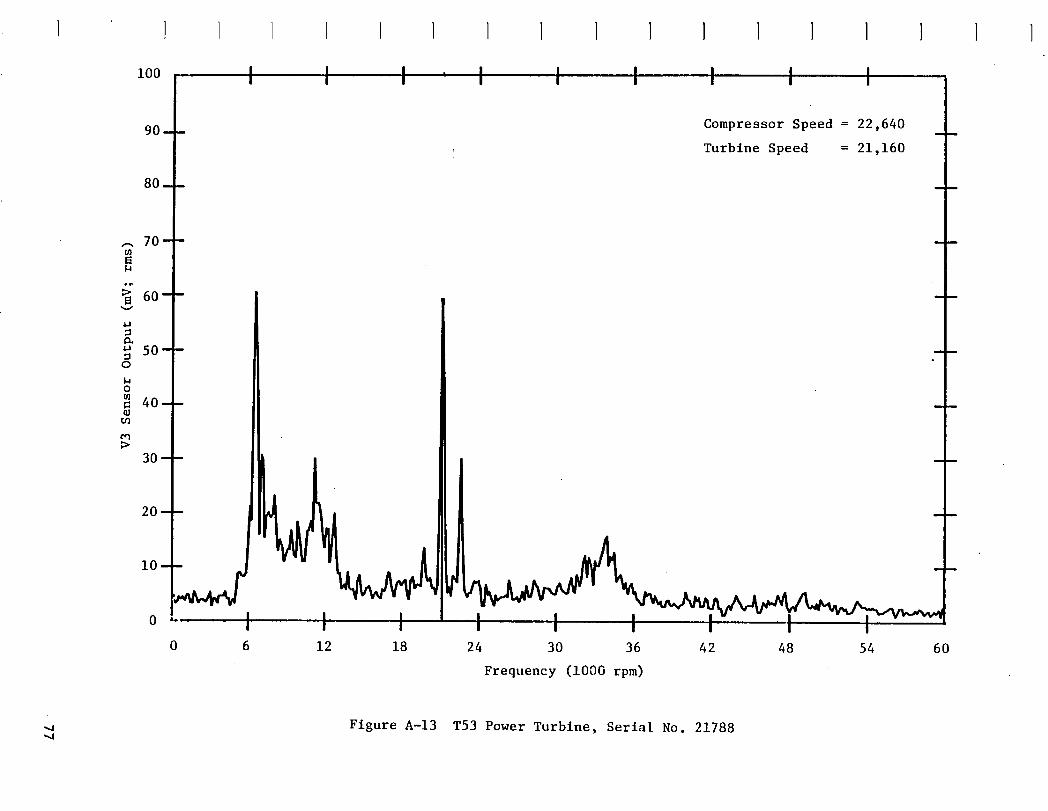
lOO { I { { I I { { {
90--- Compressor Speed = 22,640
Turbine Speed = 21,160
._ 70-- m
o_
60-- ---v
50---o
o
40--
o_>
30---
20--- _
10_ _
0 6 12 18 24 30 36 42 48 54 60
Frequency (1000 rpm)
Figure A-13 T53 Power Turbine, Serial No. 21788

., lOO I I I ' I I I I I I
Compressor Speed = 22,64090 ....
Turbine Speed _ 21,160
0- - _
lo--o I I I I I I0 6 12 18 24 30 36 42 48 54 60
Frequency (i000 rpm)
Figure:A-14 T53 Power Turbine, Serial No. 289659
I I I I I ] I I ] ] I ] I ] , I I i

{ { I I I I I } ) { { I } { )
_oo { { { { { { { l {
90--- Compressor Speed = 22,640
Turbine Speed = 21.160
80---
_- 70---{0
60--- --
= 50---O
o{/l
= .40- -aJ
>
30--
20_ _ _
| . _ L| " ,
0 6 12 18 24 30 36 42 48 54 60
Frequency (I000 rpm)
Figure A-15 T53 Power Turbine, Serial No. P5132

5o I I I I I I I I ICoO
Compressor Speed = 22,640 m n
Turbine Speed = 21,160
m
i0 -
0 6 12 18 24 30 36 42 48 54 60
Frequency (i000 rpm)
Figure A-16 T53 Power Turbine, Serial No. 82C004

1 1 1 1 1 1 1 1 1 1 1 1 1 1 1 1
I I50 I I , I t t t , I
Compressor Speed = 22,640 m
Turbine Speed ffi21.160
0
0 6 12 18 24 30 36 42 48 54 60
Freauencv (1000 rpm)
Figure A-17 T53 Power Turbine, Serial No. 82C012

1oo I I I I I I I I Ioo
90--- Compressor Speed = 22,640Turbine Speed = 21,160
0u _ a m
"_ 70-- m
_ 60-- _
=
50--o
o
40 ....
03>
30--
20-- _ --
i0--
oJw'a i0 6 12 18 24 30 36 42 48 54 60
Frea.enev (10C0 rpm)
Figure A-18 T53 Power Turbine, Serial No. 80KO03P
I I ] I I ] 1 I ] ] I ] I ] ] ! I I ]

APPENDIX B
T55 ENGINE SPECTRUM PLOTS
83


! } I 1 1 1 / } I ] 1 I ) I 1 I I
loo I I ' I I I I I I I
90- - Turbine Speed _ 15,600 rpm --
Compressor Speed _ 17,250 rpm
80- -
70--- m mO_
6o--4..t
50--o
140
4o-- qmu_
>30--
10
o ! I0 6 12 18 24 30 36 42 48 54 60
Frequency (I000 rpm)
Figure B-I T55 Power Turbine, Serial No. 265499

lOO I I i I I I I I I
90- " Turbine Speed - 15,600 rpm - -_mpressor Speed = 17,250 rpm
80- -
0 II
0 6 12 18 24 30 36 42 48 _6 6Q
Frequency (1000 rpm)
Flgure B-2 T55 Power Turbfne, Serial No. 95259
1 l I I } I I i I 1 1 1 } i I I I

] ! ! ! ! ! ] } 1 ] 1 t ! } ! 1
loo I I I I I I I I I
Turbine Speed = 15,600 rpm90 -
Compressor Speed = 17,250 rpm
0m m w
u_
70-- m
60-- m4-I
o 50 ....
0
4o__u_
>
30_
20 m
lO
o I t t t t t0 6 12 18 24 30 36 42 48 54 60
Frequency _lO00 rpm)
Figure B-3 T55 Power Turbine, Serial No. U00316

= lOO I I ' I I I I I I Ico
90--- Turbine Speed = 15,600 rpm
Compressor Speed = 17,250 rpm
Irk_ _ m0 6 12 18 24 30 36 42 48 54 60
Frequency (i000 rpm)
Figure B-4 T55 Power Turbine, Serial No. 265539
I 1 i 1 I I i I ! 1 I I i J J i J i

I00 I m ., I I I I I I I
90-- Turbine Speed = 15,600 rpm - -
Compressor Speed - 17,250 rpm
lm
m 70---
,_ 60--- _
iJo 50 ....o
1,4Om
m 40--r_
cq
30---
20 m m
10
I0 I
0 6 12 18 24 30 36 42 48 54 60
Frequency (I000 rpm)
m Figure B-5 T55 Power Turbine, Serial No. U00589

loo I I I I I I I I I0
90-- Turbine Speed = 15,600 rpm --
Compressor Speed - 17,250 rpm
u
80--
J'_ m
70--
v 60_ ---
50--- --(:3
I..io
4o--
>
30--
o I I0 6 12 18 24 30 36 42 48 54 60
Frequency (lO00 rpm)
Figure B-6 T55 Power Turbine, Serial No. 265604

' ! ! ! ! I 1 / 1 / l I I 11 1 1 I ;
I I llOO , , , | F _ t t 1
90-- Turbine Speed = 15,600 rpm m
Compressor Speed = 17,250 rpm
80- -
70-- m
v 60--
4_
so-- --o
40-- m
>
30m
20.-- liI,:
,o ,Jo ,--.....• --_ ,,,' - , I : t t -1 ' I ,I I
O 6 _ 12 18 24 30 36 42 48 54 60
Frequency (1000 rpm)
Figure K-7 T55 Power Turbine, Serial No. 268922

Ioo I I I I i I I I II,a
90_ Turbine Speed = 15,600 rpm --
Compressor Speed = 17,250 rpm
m D
70-- m
v 60-- m4J
4_
o 50---taOO]
40-- --
>
30-- m
0__ _
o ' ' t | tI I0 6 12 18 24 30 36 42 48 54 60
Frequency (I000 rpm)
Figure B-8 T55 Power Turbine, Serial No. 268541
] I J J 1 I 1 I I I } 1 I I i 1

1 ! ! ) I 1 1 ', _ I 1 I I _ 1 1 1 i
loo I I I I I I I I ITurbine Speed = 15,600 rpm
90 ....Compressor Speed = 17,250 rpm
0 _ -
o I0 6 12 18 24 30 36 42 48 54 60
Frequency (1000 rpm)
_ Figure B.-9 T55 Power Turbine, Serial No. 265566

,_ 10o .... _ I I t t t I I t
Turbine Speed = 15,600 rpm
90-- 1 Compressor Speed = 17,250 rpm80-- [ --
y
g ,o__,I
llJ ..50-- t wo
o
40-- i m
30-- ! mI'
!1 --h}I --
o I I- -I .1 "t I I _.0 6 12 1B 24 30 36 42 48 54 60
Frequency (lO00 rpm)
Figure B-10 T55 Power Turbine, Serial No. U00295
1 1 I 1 1 ) I 1 ) 1 I 1 I } 1 ] I 1

lOO I I I I I I I I I
90--- Turbine Speed = 15,600 rpm
Compressor Speed = 17,250 rpm
80m
70-- ---o_
>
v 60m
o 50--
om=
40---
0 _ i m
0 mn M
o t I t !0 6 12 18 24 30 36 42 48 54 60
Frequency (i000 rpm)
F%gure B-II T55 Power Turbine, Serial No 265549

,_ lOO_ I I I I I I ,' ,' ',o_
90- - Turbine Speed - 15,600 rpm _ -
Compressor Speed - 17,250 rpm
0 m n m
m
70--
_60-- " -4J
4J
o 50--I.i0u]
m 40--
i
30 "-
20_ _ _
lOo-!_" ', --0 3 6 9 12 15 18 21 24 27 30
Frequency (i000 rpm)
Figure B_12 T55 Power Turbine, Serial No. M265682 °
1 I I i I } J i ) I 1 t } 1 ] I I !

! I 1 _ I 1 _ ! I 1 l ! ! _ 1 I I
lOO i I l I I' i I I i
90--- Turbine Speed = 15,600 rpm --
Compressor Speed = 17,250 rpm
80....
\
70--I,.4
60--v
=
50--0
0
40--
>
30_
20 w
i0-- ,1_/_o t I _ {
0 3 6 9 12 15 18 21 24 27 30
Frequency (I000 rpm)
Figure B-13 T55 Power Turbine, Serial No. 261845

lOO I { { { l { I { {
90- Turbine Speed = 15,600 rpm - -
Compressor Speed = 17,250 rpm
80-- -
20--
lOu --
o0 6 12 18 24 30 36 42 48 54 60
Frequency (I000 rpm)
Figure B-14 T55 Power Turbine, Serial No. 254954
I I i I } I i I 1 ) I } } I I I 1

loo I _ I I I I I I I
90-- Turbine Speed - 15,600 rpm --
Compressor Speed - 17,250 rpm
80-- -
"_ 70--
_60--m B
4J
4-J
o 50--140
4o--P
30--
20_ --m m
0 6 12 18 24 30 36 42 48 54 60
Frequency (1000 rpm)
Figure B-15 T55 Power Turbine, Serial No. U00259

!_, loo I , I I I I I I I0o
Turblne Speed - 15,600 rpm90--
Compressor Speed - 17,250 rpm
0 u _ m
70-- m
v 60--cA
¢J
o 50--
0
I:l40 ....
>
30--
0 m _ m
10--
....iv',_t. ,...,..l _,?._o , I I t t I I ,0 6 12 18 24 30 36 42 48 54 60
Frequency (I000 rpm)
Figure B-16 T55 Power Turbine, Serial No. 265530
i i I i ] i I I I i I I i } i i i }

1 I ! } _ ! l 1 ! I I I ! ! I ! 1 T
I I . I I IlOO , , I , , I , I I
90- - Turbine Speed = 15,600 rpm
Compressor Speed - 17,250 rpm
80 m _
70 ....
_60 ....4J
4J
50-- -._ko
4o--P_
30-- _
20 _ _ _
lo__ -o_-, , , _0 6 12 18 24 30 36 42 48 54 60
Frequency (1000 rpm)
Figure B-17 T55 Power Turbine, Serial No. 261830o

lOO I I I I I I I I IF-AO
90---- Turbine Speed m 15,600 rpm --
Compressor Speed = 17,250 rpm
80--- _
0_ m m _
10-_ _0
0 6 12 18 24 30 36 42 48 54 60
Frequency (1000 rpm)
Figure B-18 T55 Power Turbine, Serial No. 268934
I I I I I I i I I I I I I I I I I )

1 _ I I 1 ! ! 1 l 1 1 I _ 1 I ! 1
m A .,|1oo I , : ", I I '" I I I I
90- - Turbine Speed - 15,600 rpm - -Compressor Speed = 17,250 rpm
20-- -- m
00 6 12. 18 24 30 36 42 48 54 60
Frequency (I000 rpm)
Figure B-19 T55 Power Turbine, Serial No. U00212O

I

REFERENCES
i. Tessarzik, Juergen M. "Flexible Rotor Balancing by the Influence Coeffi-
cient Method - Multiple Critical Speeds with Rigid or Flexible Supports."
NASA CR-2553, 1975.
2. Walter, Thomas J. "Study of T53 Engine Vibration." NASA CR-135449, 1978.
3. Martin_ Michael R. "T55 Power Turbine Rotor Multiplane-Multispeed
Balancing Study." NASA CR-167891, 1982.
105

I

DISTRIBUTIONLIST
Contract gAS3-20609
RECIPIEET )lO. OFCOPIES RECIPIEET NO. OFCOPIES
NASALewis ResearchCenter 14echanlca1Technology, Inc.21000 Brookpark Road 968 Albany-ShakerRoadCleveland, OH 44135 . La+nm, gY 12110Attn: O.P. Nmlng _ 23-3 (20+ r_produclble) At+n: Library I
H.O. 51one _ 3-5 IL. J. KIraly 14523-2 1 Matt & ghf+ney Afrcraft-FROC0. W. OHer MS85-2 1 P.O. Box2691
__ M.C. govach MS500-305 2 W. PalmBeach, FL 33402Library MS60-3 1 At+n: V.S. Fehr 1Report Control Off. MS60.1 2 Library 1Technolog),Utl I J-zatJon Off. 1457-3 1 Wflllams International
J. Acurto 146302-2 1 2280 W. Maple RoadC. L. Walker MS302-2 1 Walled Lake, HI 48088G. J. Weden 145302-2 1 At+n: Library 1L. O. gtchols 14649-6 1
N_A _lentlffcand T_hnlcal Infor_atlonFac111_ Air ForceAero_pulslon Laboratory-- P.O. Box8757 Wright Patterson AFB, OH 45433
Bait/Wash. International Airport, 140 21240 At+n: AFAPL/SFL/H.F. Jones 1AF_AL/POTCIL.G111 IAt+n: AccesstonJngDepartment 25 AFWN./NASA-PO/E.E. Batley 1NASAAmesResearchCenterMoffettFfeld, CA 94035 AeroJet-General co_oratlonAt+n: Library 1 1100 W. Hollyvale
Azusa, CA 91702NASADryden Fllght ResearchFac111ty At+n: Ltbrary 1P. O. Box273
-- Edwards,CA 93523 AerospaceCorporationAt+n: Library 1 P.O. Box90585los Angeles, CA 91745g_ GoddardSpaceFllght Center At+n: Library 1Greenbelt, MO 28771At+n: Ltbrary I _tt Tu_Jne _gJne CO.111 S. 34thStreet
Jet P_pulslonLaboratory _oenlx,_ 850104800 OakGroveOrtve At+n: LJbrary 1Pasadena,CA 91103 T. Howell 1
__ At+n: Ltbrary 1AfResearchHanufacturfng Company
NASALangleyResearchCenter 9851 SepulvedaBlvd.Hampton,VA 23655 LosAegeles, CA 90009At+n:, Ltbrary 1 At+n: Library I
-- NASAJohnsonSpaceCenter Bottelle Colu_lbusLabsHouston, TX 77058 505 Kfng AvenueAt+n: Lfbrary 1 Coleus, OH 43201
At+n: Ltbrary 1
_-- gASA14arsha11SpaceFlfght Center BoetngCompany_rsha11 SpaceF11ghtCenter, AL 35812 Aerospace OtvtstonAt+n: Lfbrary 1 P.O. BOx3707
rn 14/L. Schutzenhofer 1 Seattle, WA 98124
NASAHeadquarters At+n: Lfbrary IWashington,OC Z0545 Boetn9CompanyAt+n: R/R.Colladay 1 YertolDivision, Boeing Center
RT.6/L. Harrts 1 P.O. Box16858RT-6/C. Rosen I Phfladelphta, PA 19142
•-- AVCO-Lycomtng At+n: Library I550 S. 14atnStreet General Electrtc CompanyStratfo_l,'CT 05497 Atrcraft Engfne GroupAt+n: E. Beardsley 1 1000 Western Avenue
14.S4boe 1 Lynn, _ 01910LJbra_ 1 At+n: R.A. Dangelmafer 1
Curtis-Wright Corp. W. _ Kurz IOnePassatc Street
goodrtdge, _lJ 07075 General ElectricCompany--- At+n: Ltbrary 1 Butldtng 58-219
Franklin Institute ResearchLaboratories Schenectady,NY 123452Qth and Parkway At+n: E.R. Booser 1
Philadelphia, PA 19103 General E'lectrfc Company.--- At+n: Library 1 MechanicalTechnologyLaboratory
Frictlon & l_brfcatfonLaboratory I _ Center
KamanAerospacecorporation Schenectady,MY 12301At+n: Library 1Old MfndsorRoad__ Bloomfield, CT 06002
At+n: LIbrary 1
107

RECZPZENT NO.OFCOPZES RECTP(ENT NO.OFCOPIES
General Motors Corporation U.S. Army (AVSCOM)All|son Division 4300 Coodfellow Blvd.indianapolis, IN 46208 St. Louis, HO 63120Atl_: Libraw 1 Attn: E.J. Hollman, ORDAV-Q 1
W. H. Parker 1 J.T. Conrey, DROAV-QE 1N. Raglan, ORDAV-QE 1
HughesAircraft CorporationConttndaand Teale Avenue SouthwestResearch InstituteColver City, CA 90230 P.O. Box28510 __Attn: Library 1 San Antonio, TX 78284
Atto: Ltbrary 1Tnstttute for Defense Analyses400 Arly-Ravy OrtveArlington, VA 22202 TeledyneCA£Attn: Library 1 1330 LaskeyRoad
Toledo, OH 43512LockheedHtsstles and SpaceCompany Attn: R.H. _aylord 1P. O. BoxS04Sunnyvale, CA 94088 Ingersoll-Rand CorporationAttn: Library l Philltpsburg, _ 08865
Atto: R. _ Kirk 1Rational Science FoundationEngineering Division University of Vtrginta1800 "G" Street, _ Schoolof Engineering & Applied Science.Washington,DC 20540 Charlottesville, VA 22901Attn: Library 1 Attn: Or. Edgar J. Gunter l
Dr.Paul Allalre 1_val Atr SystemsCommandWashington,0C 20360 The VibrationInstituteAttn: Library 1 101 W. 55th Street, Suite 206 --
ClarendonHills, (L 60514TransamertcaDelaval Atto: Or. R. L. Eshleman 1853 _lotttnghm WayTrenton, _ 08638 Texas AM4UniversityAttn: E.A. 8ulanowskt I Depar1=entof Mechanical Engineering
College Station, TX 77843Naval Atr Propulsion Center Attn: Dr. J. H. Vance 1Trenton, NJ 08628Atto: R. Valor1 1 Corpus Christi Amy Depot
CorpusChristi, TX 78419Rocl_ell (nto_tio_1 Attn: R.W. Ladner 1RocketdyneOfvislon WI11iamWiIson 16633 ConogaAvenue DonWells, SOSCC-MP 1CanogaPark, CA 91304 G. Grohmn 1Attn: R.F. Beat_y 1 F.P. Gross, SCSCC-MPD l
Office of Naval ResearchArl|ngton, YA 22217Attn: Llbrary l
Sunds1_andDenver2400 W. 70th AvenueDenver, CO 80221Attn: Ltbrary 1
U. S. Amy Engineering R&OLabs_s Turbine Test FacilityFord:8elvoir, VA 22060Attn: _. _Im 1
UnitedTechnologies Corporatlon --I_att &Whttney AircraftDivision400 MatnStreetE. Hartford,_ 05108Atto: O.H. H1bner I
P. 8retm 1Library 1
United TechnologiesCorporationSikorsky Mrcraft DivisionStratford, CT 06497Ate: L. Burroughs 1
U. S. ArmyResearch & TechnologyLabsFort Eustts, VA 23604Atto: Library 1
John White 1
108

I

ml