ibm z systems processor optimization primer.pdf
TRANSCRIPT
C. Kevin Shum
Distinguished EngineerIBM z Systems Microprocessor DevelopmentMember of IBM Academy of Technology
IBM z Systems Processor Optimization Primer(March 2016)

TrademarksThe following are trademarks of the International Business Machines Corporation in the United States, other countries, or both.
The following are trademarks or registered trademarks of other companies.
* All other products may be trademarks or registered trademarks of their respective companies.
Notes:
Performance is in Internal Throughput Rate (ITR) ratio based on measurements and projections using standard IBM benchmarks in a controlled environment. The actual throughput that any user will experience will vary depending upon considerations such as the amount of multiprogramming in the user's job stream, the I/O configuration, the storage configuration, and the workload processed. Therefore, no assurance can be given that an individual user will achieve throughput improvements equivalent to the performance ratios stated here.
IBM hardware products are manufactured Sync new parts, or new and serviceable used parts. Regardless, our warranty terms apply.
All customer examples cited or described in this presentation are presented as illustrations of the manner in which some customers have used IBM products and the results they may have achieved. Actual environmental costs and performance characteristics will vary depending on individual customer configurations and conditions.
This publication was produced in the United States. IBM may not offer the products, services or features discussed in this document in other countries, and the information may be subject to change without notice. Consult your local IBM business contact for information on the product or services available in your area.
All statements regarding IBM's future direction and intent are subject to change or withdrawal without notice, and represent goals and objectives only.
Information about non-IBM products is obtained Sync the manufacturers of those products or their published announcements. IBM has not tested those products and cannot confirm the performance, compatibility, or any other claims related to non-IBM products. Questions on the capabilities of non-IBM products should be addressed to the suppliers of those products.
Prices subject to change without notice. Contact your IBM representative or Business Partner for the most current pricing in your geography.
Adobe, the Adobe logo, PostScript, and the PostScript logo are either registered trademarks or trademarks of Adobe Systems Incorporated in the United States, and/or other countries.
Cell Broadband Engine is a trademark of Sony Computer Entertainment, Inc. in the United States, other countries, or both and is used under license therefrom.
Java and all Java-based trademarks are trademarks of Sun Microsystems, Inc. in the United States, other countries, or both.
Microsoft, Windows, Windows NT, and the Windows logo are trademarks of Microsoft Corporation in the United States, other countries, or both.
Intel, Intel logo, Intel Inside, Intel Inside logo, Intel Centrino, Intel Centrino logo, Celeron, Intel Xeon, Intel SpeedStep, Itanium, and Pentium are trademarks or registered trademarks of
Intel Corporation or its subsidiaries in the United States and other countries.
UNIX is a registered trademark of The Open Group in the United States and other countries.
Linux is a registered trademark of Linus Torvalds in the United States, other countries, or both.
ITIL is a registered trademark, and a registered community trademark of the Office of Government Commerce, and is registered in the U.S. Patent and Trademark Office.
IT Infrastructure Library is a registered trademark of the Central Computer and Telecommunications Agency, which is now part of the Office of Government Commerce.
Not all common law marks used by IBM are listed on this page. Failure of a mark to appear does not mean that IBM does not use the mark nor does it mean that the product is not
actively marketed or is not significant within its relevant market.
Those trademarks followed by ® are registered trademarks of IBM in the United States; all others are trademarks or common law marks of IBM in the United States.
For a more complete list of IBM Trademarks, see www.ibm.com/legal/copytrade.shtml:
*BladeCenter®, CICS®, DataPower®, DB2®, e business(logo)®, ESCON, eServer, FICON®, IBM®, IBM (logo)®, IMS, MVS, OS/390®,
POWER6®, POWER6+, POWER7®, Power Architecture®, PowerVM®, PureFlex, PureSystems, S/390®, ServerProven®, Sysplex Timer®, System p®, System p5, System x®, z Systems®, System z9®, System z10®, WebSphere®, X-Architecture®, z13™, z Systems™, z9®, z10, z/Architecture®, z/OS®, z/VM®, z/VSE®, zEnterprise®, zSeries®

Documentation Objectives
• Provides an overview of the processorsubsystems of IBM’s z Systems, with focus on the core microarchitectures from z196 to z13
• Gives high level insights with information and potential methods to optimize for code performance
• Fosters a deep technical exchange with non-IBM development teams around the z Systems’ open source ecosystem to encourageperformance optimization tailored towards z System processors
“tell us what you need to know”
•If needed, this document may be updated with more information in the future. However, it is not intended to be a comprehensive write-up and should not replace any formal architecture documents

© 2016 IBM Corporation4
z/Architecture and Implementation
z/Architecture1 is a 64 bit architecture that is supported by IBM’s z Systems microprocessors– A Complex Instruction Set Computer (CISC) architecture, including highly capable (and thus complex) instructions
– Big-Endian (BE) architecture (vs. Little-Endian) where bytes of a multi-byte data element are stored with the most
significant byte (MSB) at the lower storage address
z/Architecture grows compatibly upon each generation, and includes many innovative features– Typical load/store/register-register/register-storage instructions, including logical and arithmetic functions
– Branch instructions supporting absolute and relative offsets, and subroutine linkages
– Storage-storage instructions, e.g. “MOVE characters (MVC)” (for copying characters), including decimal arithmetic
– Hexadecimal, binary and decimal (both IEEE 754-2008 standard) floating-point operations
– Vector (SIMD) operations (from z13 on), including fixed-point, floating-point, and character string operations
– Atomic operations including COMPARE AND SWAP, LOAD AND ADD, and OR (immediate) instructions
– Hardware transactional memory, through the Transactional Execution Facility (since zEC12), including the definition
of a constrained transaction that can be retried by the hardware
– Two-way Simultaneously Multi-Threading (SMT-2) support (since z13)
Highly complex instructions are implemented through a special firmware layer – millicode2
– Millicode is a form of vertical microcode
– An instruction implemented in millicode (a millicoded instruction) is executed by the hardware similar to a built-in
subroutine call, that transparently returns back to the program when the millicode routine ends
– A millicode instruction routine consists a subset of the existing instructions in the z/Architecture, with access to its
own pool of internal registers in addition to program registers and specialized hardware instructions
– Some complex routines may involve operating in conjunction with a private co-processor or special hardware that is
only accessible by millicode
– The routine is pre-optimized for each processor generation
© 2016 IBM Corporation5
Highlights of the Recent Microprocessor Cores
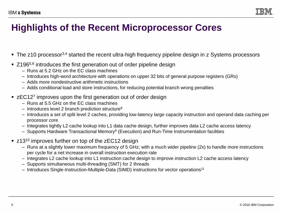
The z10 processor3,4 started the recent ultra-high frequency pipeline design in z Systems processors
Z1965,6 introduces the first generation out of order pipeline design– Runs at 5.2 GHz on the EC class machines
– Introduces high-word architecture with operations on upper 32 bits of general purpose registers (GRs)
– Adds more nondestructive arithmetic instructions
– Adds conditional load and store instructions, for reducing potential branch wrong penalties
zEC127 improves upon the first generation out of order design – Runs at 5.5 GHz on the EC class machines
– Introduces level 2 branch prediction structure8
– Introduces a set of split level 2 caches, providing low-latency large capacity instruction and operand data caching per
processor core
– Integrates tightly L2 cache lookup into L1 data cache design, further improves data L2 cache access latency
– Supports Hardware Transactional Memory9 (Execution) and Run-Time Instrumentation facilities
z1310 improves further on top of the zEC12 design– Runs at a slightly lower maximum frequency of 5 GHz; with a much wider pipeline (2x) to handle more instructions
per cycle for a net increase in overall instruction execution rate
– Integrates L2 cache lookup into L1 instruction cache design to improve instruction L2 cache access latency
– Supports simultaneous multi-threading (SMT) for 2 threads
– Introduces Single-Instruction-Multiple-Data (SIMD) instructions for vector operations11
© 2016 IBM Corporation6
Core 0
L3_0
L3_1
L2
CoPMCU
L2
Core 1
L3_0
L3_1
Core 2
L2
CoP GX
L2
Core 3
L3_0 Controller
L3_1 Controller
MC
IOs
MC
IOs
GX
IOs
GX
IOs
L3B
L3B
Core 0
L3_0
L3_1
L2
CoPMCU
L2
Core 1
L3_0
L3_1
Core 2
L2
CoP GX
L2
Core 3
L3_0 Controller
L3_1 Controller
MC
IOs
MC
IOs
GX
IOs
GX
IOs
L3B
L3B
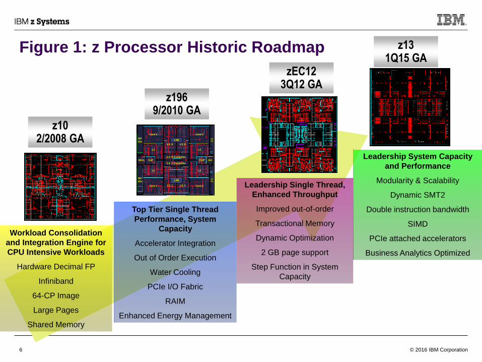
z1969/2010 GA
zEC123Q12 GA
z102/2008 GA
z131Q15 GA
Leadership Single Thread,
Enhanced Throughput
Improved out-of-order
Transactional Memory
Dynamic Optimization
2 GB page support
Step Function in System
Capacity
Top Tier Single Thread
Performance, System
Capacity
Accelerator Integration
Out of Order Execution
Water Cooling
PCIe I/O Fabric
RAIM
Enhanced Energy Management
Leadership System Capacity
and Performance
Modularity & Scalability
Dynamic SMT2
Double instruction bandwidth
SIMD
PCIe attached accelerators
Business Analytics Optimized
Workload Consolidation
and Integration Engine for
CPU Intensive Workloads
Hardware Decimal FP
Infiniband
64-CP Image
Large Pages
Shared Memory
Figure 1: z Processor Historic Roadmap

© 2016 IBM Corporation7
System Cache Structure
A z system consists of multiple computing nodes, connected through the global fabric interface, each system node includes
a number of processor (CP) chips (6 in z196, 6 in zEC12 and 3 in z13)
– In z10, z196, and zEC12, the system consists of up to four nodes, with each node connected to each other node
through the L4 caches
– In z13, the system consists of up to eight nodes, packaged as one pair of nodes per drawer
• The nodes on each drawer are connected to each other through the L4 caches
• Each node is connected to the corresponding node on each other drawer through the L4 caches
• The three CP chips in each node are connected to each other through the shared on-chip L3 caches
Each processor (CP) chip includes a number of processor cores
– There are 4 cores in a z196 CP chip, 6 in zEC12, and 8 in z13
– Each core includes both local L1 instruction and operand data caches, and a local L2 cache
– Since zEC12 and z13, a pair of L2 caches supports instruction and operand data separately
– Each L2 cache is connected to the on-chip (shared) L3
Caches are managed “inclusively” such that contents in lower level caches are contained (or tracked) in the higher level
caches
– In z13, the L4 maintains a non-data inclusive coherency (NIC) directory to keep track of cache line states in the L3
without having to save a copy of the actual cache line data
– Cache lines are managed in different states (simplistic view):
• “exclusive” (at most 1 core can own the line to store or update at any time);
• “shared” or "read-only" (can be read by 1 or more cores at any time); and
• “unowned” (where no core currently owns the cache line)
– When a cache line is shared, and a processor wants to store (update) one of the elements, a cache coherency delay
is required to invalidate all existing read-only lines so this processor can be the exclusive owner
– Similarly, an exclusive line will need to be invalidated before another processor can read or write to it
© 2016 IBM Corporation8
Near-Core Cache Operations
The L1 and L2 (private) caches are store-through, i.e., each storage update is forwarded immediately to the shared L3
cache once the instruction performing the update has been processed– For reference, L3 and L4 (shared) caches are store-in, i.e., storage updates are kept in the cache until the cache entry is
replaced by a new cache line or being evicted to move to another L3 or L4 cache
The cache line size (for all caches) being managed across the cache subsystem is currently 256 bytes – Although the line size has been stable across recent machines, it should not be relied upon
– However, it is unlikely that the cache line size will grow beyond 256 bytes
– EXTRACT CPU ATTRIBUTE instruction should be used to obtain information about the cache subsystem, e.g. cache sizes and
cache line sizes for each cache level
The z/Architecture and the processor design supports self-modifying code– However, this can be a costly event due to movement of cache lines between the instruction and data caches (L1 and L2)
– Due to out of order and deep pipelining; self-modifying code becomes even more expensive to use and is not advised
– Even if there is no intention to update the program code, false sharing of program code and writeable operand data in the same
cache line will suffer similar penalties
The L1 implements a “store-allocate” design where it has to obtain the exclusive ownership before it can store into a cache
line– The storing instruction will stall in the pipeline until the correct cache state is obtained
– It is important to not share writeable data elements in the same cache line for independent multiprocessor operations
The associativity of a cache (shown in next page) reflects how many available compartments a particular cache line can
be stored in– For a 8-way associative cache, a cache line (based on its line address) can be saved in one of 8 slots

© 2016 IBM Corporation9
Figure 2: Cache Hierarchy and sizes (zEC12 and z13)
Store-through
Parity protected
Store-Through
Parity protected
Store-in
ECC protected
Store-in
ECC protected
Global Fabric Interface
zEC12 (book)
4 L4s
48 MB Inclusive of L1,L1+,L2
12-way Set Associative
256B cache line size
1 MB L1+* Inclusive of D-L1
1 MB L2 Inclusive of L1,L1+*
8-way* Set Associative
256B cache line size
64 KB I-L1 + 96 KB D-L1
6-way Set Associative D-L1
4-way Set Associative I-L1
256B cache line size
384 MB
Inclusive of L1,L1+,L2,L3
24-way Set Associative
256B cache line size
Store-through
Parity protected
Store-Through
Parity protected
Store-in
ECC protected
Global Fabric Interface
z13 (half of drawer)
8 L4s
64 MB Inclusive of L1,L2
16-way Set Associative
256B cache line size
2 MB I-L2 Inclusive of I-L1
2 MB D-L2 Inclusive of D-L1
8-way Set Associative
256B cache line size
96 KB I-L1 + 128 KB D-L1
8-way Set Associative D-L1
6-way Set Associative I-L1
256B cache line size
1st Level:
2nd Level:
3rd Level:
480 MB cache +
224 MB Non-data Inclusive
Coherency (NIC) Directory
Inclusive of L1,L2,L3
30-way Set Associative L4
14-way Set Associative NIC
256B cache line size
4th Level:Store-in
ECC protected
1st Level:
2nd Level:
3rd Level:
4th Level:
* The L1+/L2 design in
zEC12 is too complicated for
this document. One can
treat it as two L2s, each
1MB and 8-way set
associative
L2L1
L2L1
L2L1
L2L1
384MB
Shared eDRAM L4
6 L3s,36 L1 / L2s
L2L1
48MB ShreDRAM L3
L2L1
L2L1
L2L1
L2L1
L2L1
L2L1
L2L1
48MB ShreDRAM L3
480MB
Shared eDRAM L4
L2L1
L2L1
L2L1
L2L1
L2L1
L2L1
L2L1
L2L1
64MB ShreDRAM L3
L2L1
L2L1
L2L1
L2L1
L2L1
L2L1
L2L1
L2L1
64MB ShreDRAM L3
NIC
Directory
Intra-node Interface
3 L3s and24 L1 / L2s

© 2016 IBM Corporation10
High Level understanding of the microprocessor core
The z microprocessor cores can be simplified into a number of functional units (which are further
described in some published papers):
– Branch prediction unit• 2 level structure of branch histories; advanced design predicts both targets and directions
– Instruction caching and fetching unit• Based on branch prediction information, delivers instructions in a seamless fashion
– Instruction decoding and issuing unit• Decodes instructions in groups; issues micro-operations out-of-order to the execution units
– Fixed-Point Execution unit• Executes most of the fixed-point operations, and (in z13) fixed-point divides
– Vector & Floating-Point Unit• Handles floating-point arithmetic operations, complicated fixed-point operations, and (in z13) vector operations
– Load/Store (or Data-caching) unit• Accesses operand data for both fetch (load) or store (update) operations
– Co-processor unit• Supports data compression, cryptographic functions, UTF translations (since zEC12); operates through
millicode routine
– Second Level Translation and Cache unit• Maintains the private second level translation-lookaside-buffer (TLB2) and cache (L2)
We will give a high level overview of the microprocessor design features
– For more details, please refer to articles listed in the reference section near the end

© 2016 IBM Corporation11
Branch Prediction Unit
Branch prediction is an important feature in any modern microprocessor design
Branch prediction in z processors is performed 'asynchronously' to instruction processing– The branch prediction logic can find/locate/predict future occurrences of branch-type instructions (including calls and
returns) and their corresponding directions (taken or not taken) and targets (where to go next) on its own without
requiring / waiting for the downstream pipeline to actually decode / detect a branch instruction
– The branch prediction logic tries its best in predicting the program path much further into program code than where
the instruction fetching unit is currently delivering instructions at (and should be way ahead of where the execution
engines are executing)
The branch prediction logic adapts many advanced algorithms / structures in maintaining and predicting
branching behaviors in program code, as seen in Figure 3, including– First level branch target buffer (BTB1) and branch (direction) history table (BHT1)
– Second level target and history buffers (BTB2 and BHT2) (introduced since zEC12) with a pre-buffer (BTBP) used as
a transient buffer to filter out unnecessary histories
• Note: BHT2 is only used in zEC12
– Accelerators for improving prediction throughput (ACC) by “predicting the prediction” (since zEC12) so it can make a
prediction every cycle (for a limited subset of branches)
– Pattern based direction and target predictors (PHT and CTB) to predict based on “how the program gets here” branch
history (that represents the program flow), e.g. for predicting an ending of a branch on count loop, or a subroutine
return that has multiple callers
The branch prediction logic communicates its prediction results to the instruction fetching logic through
an overflow queue (BPOQ); such that it can always search ahead of where instructions are being fetched

© 2016 IBM Corporation12
Figure 3: Branch Prediction Structure
Instruction
fetch
Speculative
BHT & PHTPHT CTB
Branch Prediction LogicBranch
Prediction
Overflow
Queue
(BPOQ)
BTB2
(zEC12+)
BTBP
(zEC12+)
BTB1 and
BHT1
ACC
(zEC12+)
new branches
reload
evict
used
SMRU
(z13)
BHT2
32k entries
(zEC12 only)

© 2016 IBM Corporation13
Table 1: Branch Prediction ResourcesLabel Structure Name Description z196 zEC12 Z13
Rows x Sets (where applicable)
BTBP Branch Target Pre-buffer 0.5th level branch instruction address and
target predictor
look-up in parallel to BTB1, upon usage,
transfer to BTB1
NA 128 x 6 128 x 6
BTB1 L1 Branch Target Buffer 1st level branch instruction address and
target predictor
2048 x 4 1024 x 4 1024 x 6
BHT1 L1 Branch History Table 1st level direction predictor (2-bit) : weakly,
strongly taken, or not-taken
2048 x 4 1024 x 4 1024 x 6
BTB2 L2 Branch Target Buffer 2nd level branch instruction address and
target history buffer
NA 4096 x 6 16384 x 6
BHT2 L2 Branch History Buffer 2nd level direction 1-bit predictor for
branches not predicted ahead of time
32 K 32 K NA
ACC Column Predictor (z13) /
Fast Re-indexing Table
(zEC12)
Accelerate BTB1 throughput in finding the
“next” branch
NA 64 1024
SBHT/
PHT
Speculative BHT & PHT Speculative direction prediction with
transient updates at (out-of-order)
resolution time prior to actual completion
3 + 2 3 + 2 8 + 8
PHT Pattern History Table Pattern based tagged direction prediction 4096 4096 1024 x 6
CTB Changing Target Buffer Pattern based target prediction predicts
branches with multiple targets, typically
subroutine returns and branch tables
2048 2048 2048
SMRU Super MRU table (z13) Protect certain branches from normal LRU
out to make the BTBP more effective
NA NA 128
© 2016 IBM Corporation14
Instruction Delivery
Since z/Architecture instructions are of variable lengths of 2, 4 and 6 bytes, an instruction can start at any
halfword (integral 2-byte) granularity
Instruction fetching fetches “chunks” of storage aligned data from the instruction cache, starting at a
disruption point; e.g. after a taken branch (including subroutine calls and returns), or a pipeline flush– Up to 2 16-byte chunks for z196 and zEC12; Up to 4 8-byte chunks for z13
These “chunks” of data are then written into an instruction buffer (as a “clump”), where instructions are
extracted (or parsed) into individual z-instructions in program order
The instruction decode logic then figures out high level characteristics of the instructions, and which/how
the execution engines will handle them– Is it a storage access? A fixed-point instruction? Which execution units will be involved?
– Is it a branch-type instruction? If yes, did the branch prediction logic predict that? If not, notifies the branch prediction
logic (to restart its search) and then proceeds based on predefined static prediction rules (e.g. branch on conditions
are default to be not taken, while branch on count are defaulted to be taken)
– Is it going to be millicoded and if true, did the branch prediction logic predict that? If not, resets the front-end to start
at the corresponding millicode routine entry instruction
– For a complex instruction, does it needs to be “cracked” or “expanded” into simpler internal instructions, called micro-
operations (μop’s)? For example, a LOAD MULTIPLE instruction will be expanded into multiple “load” μops that fetch
from storage and write individual general purpose registers (GRs)
Instructions (and μop’s) are then bundled to form an instruction group (for pipeline management
efficiency), and dispatched (written) into the instruction issue queue
© 2016 IBM Corporation15
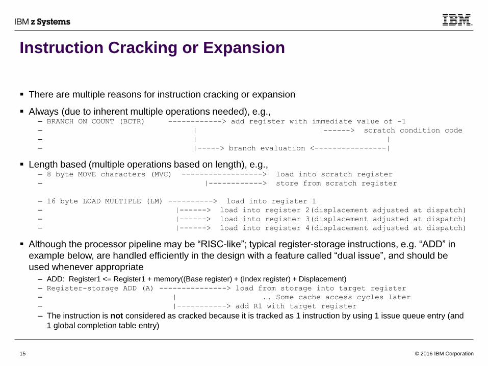
There are multiple reasons for instruction cracking or expansion
Always (due to inherent multiple operations needed), e.g., – BRANCH ON COUNT (BCTR) ------------> add register with immediate value of -1
– | |------> scratch condition code
– | |
– |-----> branch evaluation <----------------|
Length based (multiple operations based on length), e.g., – 8 byte MOVE characters (MVC) ------------------> load into scratch register
– |------------> store from scratch register
– 16 byte LOAD MULTIPLE (LM) ----------> load into register 1
– |------> load into register 2(displacement adjusted at dispatch)
– |------> load into register 3(displacement adjusted at dispatch)
– |------> load into register 4(displacement adjusted at dispatch)
Although the processor pipeline may be “RISC-like”; typical register-storage instructions, e.g. “ADD” in
example below, are handled efficiently in the design with a feature called “dual issue”, and should be
used whenever appropriate
– ADD: Register1 <= Register1 + memory((Base register) + (Index register) + Displacement)
– Register-storage ADD (A) ---------------> load from storage into target register
– | .. Some cache access cycles later
– |-----------> add R1 with target register
– The instruction is not considered as cracked because it is tracked as 1 instruction by using 1 issue queue entry (and
1 global completion table entry)
Instruction Cracking or Expansion
© 2016 IBM Corporation16
Instruction Grouping
As instructions (and μop’s) are grouped, they are subject to various grouping rules, which prevent certain
instructions from being grouped with others
In z196 and zEC12, one group of up to 3 instructions can be grouped at a time, while z13 allows two
groups of up to 3 instructions at a time
Once instructions are dispatched (or written) into the issue queue as a group, they are tracked in the
global completion table (GCT) until every instruction in the group has finished processing; then the group
is completed and retired
Some basic rules of grouping– Simple instructions, including most “register-register” and “register-storage” type instructions, can be grouped together
– Branch instructions, if second in the group, or if predicted taken, cannot be grouped with instructions after
• Best group size if taken branches are the third in a group
– μops expanded from the same instruction will usually be grouped together
• But not with other instructions (or μops) in z196, zEC12
• If expanded into only 2 μops, can be grouped with one other simple instruction after (in z13)
– Storage-storage instructions are usually grouped alone; except for the μop’s that they may be expanded into
– Other instructions that are alone in a group:
• Register-pair writers, e.g. DIVIDE (D, DR, DL, DLR), MULTIPLY (M, MR)
• Non-branch Condition code readers, e.g. ADD LOGICAL WITH CARRY (ALC*), SUBTRACT LOGICAL WITH BORROW
(SLB*)
• Explicit floating-point control register readers or writers
• Instructions with multiple storage operands
• EXECUTE or EXECUTE RELATIVE instruction or its target
– In z13, max group size will be 2 if any μop has more than 3 register sources (including Access Register usage in AR mode)
© 2016 IBM Corporation17
Instruction Dispatching
As instructions are dispatched, the source and target architected registers are renamed into a virtual pool
of physical registers and are tracked accordingly– The amount of rename tracking resources (how many inflight mappings can be tracked) and physical registers
available are key factors of the effectiveness of an out-of-order design
– In z196 and zEC12, the mapping tracker (the mapper) consists of 1 bucket of 48 mappings
• GRs: 1 mapping per each 32-bit register write, 1 mapping for each full 64-bit register write
• FPRs: 1 mapping per each 32-bit register write, 1 mapping for each full 64-bit register write
• ARs: 1 mapping per each 32-bit write
– In z13, the mapping tracker consists of 2 buckets of 64 mappings each = 128 total mappings
• GRs: 1 mapping per each 32-bit register write, the GR #’s LSB decides which bucket to use; a 64-bit register
write will require 2 mappings, one from each bucket
• FPRs: 1 mapping per each write, the FPR #’s 2nd LSB decides which bucket to use
• ARs: 1 mapping per each write, the AR #’s LSB decides which bucket to use
– In z13, multiple writes to the same register in the same group does not require separate trackers
Instructions in a group are dispatched into one of the two issue queues (side 0 and side 1). – The total size of issue queue directly relates to the overall out-of-order window and thus affects performance
– In z196 and EC12, only one instruction group can be written into one of the two queue sides at any cycle; in an
alternating fashion
– In z13, two groups can be written at any cycle with one group into each side; with the older group on side 0
The issue queue includes a dedicated “virtual branch queue” since zEC12, 1 per side, that handles
relative branch instructions whose targets are within 64 Kilobytes away– These branches will alternate to the different sides of the virtual branch queue independently of the other instructions
in the group

© 2016 IBM Corporation18
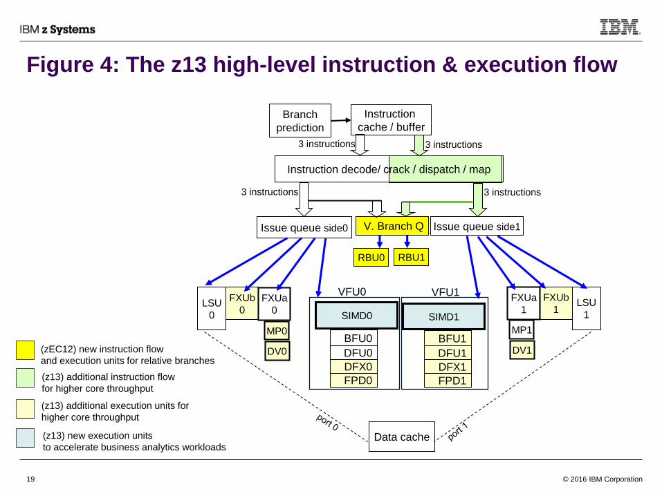
Instruction Issue and Execution
Once instructions are dispatched into the issue queues, the issue queues will issue the oldest (and
ready) instruction for each issue port to the corresponding execution engine
Each issue queue side is connected to a number of specific processing engines, using z13 as an
example as shown in Fig. 4,– There are 5 issue ports (per side; 10 total per core); each to a different engine, including
• A relative branch unit (RBU) handles relative branches
• A GR writing fixed-point unit (FXUa) handles most of the fixed-point arithmetic and logical operations; it also
includes a multiply engine and a divide engine (both being non-blocking)
• A non-GR writing fixed-point unit (FXUb) handles other fixed-point operations that does not write any GR results
• A load/store unit (LSU) port, with accesses to the data-cache, handles memory accesses
• A vector & floating-point unit (VFU), handles complicated operations
– Inside each of the VFU, there are multiple engines that execute different functions in parallel to each other (for up to
50 outstanding instructions):
• BFU that handles both hexadecimal and binary (IEEE standard) floating-point arithmetic operations, and vector
floating-point operations
• DFU that handles decimal (IEEE standard) floating-point arithmetic operations
• SIMD that further composes of multiple subunits: PM engine that performs vector permute functions; XS engine
that performs fixed-point arithmetic and logical functions; XM engine that performs several multiply functions and
ST engine that performs string-related functions
• DFX that handles decimal (BCD) fixed-point arithmetic operations
• FPD that handles divide and square root operations for both binary and hexadecimal floating-point arithmetic
– Typical pipeline delays through each of the execution engines are shown in Fig. 5
Differences vs. zEC12 and z196 are shown as colored boxes in Fig. 4
© 2016 IBM Corporation19
Figure 4: The z13 high-level instruction & execution flow
(z13) new execution units
to accelerate business analytics workloads
(z13) additional execution units for
higher core throughput
(z13) additional instruction flow
for higher core throughput
LSU
0
FXUb
0
BFU0
Issue queue side0 Issue queue side1
DFU0
SIMD0
FXUa
0LSU
1
FXUb
1
FXUa
1
Instruction decode/ crack / dispatch / map
Instruction
cache / buffer
3 instructions3 instructions
3 instructions3 instructions
V. Branch Q
RBU1RBU0
Data cache
SIMD1
VFU0 VFU1
Branch
prediction
(zEC12) new instruction flow
and execution units for relative branchesDFX0
FPD0
BFU1
DFU1
DFX1
FPD1
MP0
DV0
MP1
DV1

© 2016 IBM Corporation20
Figure 5: z13 Execution Engine Pipelines
Only 1 of 2 issue sides shown
• Typical pipeline depths and
bypass capabilities shown
• Some instructions may take
longer to execute or bypass
results
• Access registers not shown
ACC – GR access
WB – GR write back
V-ACC – FPR/VR access
VWB – FPR/VR write back
CC – condition code calculation
BYP – data bypass network cycle
FPD, DFU – functions, e.g. divide,
square-root, may take multiple
passes through the pipeline
G2F – GR to VR/FPR moves
F2G – VR/FPR to GR moves
Issue
Queue
ACC
LSU
FXA
BFU
DFU
WB
CC
WBCC
B
Y
P
DFX
XM
XS/PM
ST
VWB
WB
V-
ACC
FXB (multiply/divide
engines not shown)
VWB
V Branch
QueueRBU
ACC
ACC
FPD
SIMD
VFU
F2G
ACC G2F
© 2016 IBM Corporation21
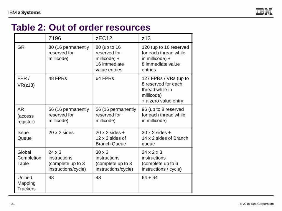
Table 2: Out of order resourcesZ196 zEC12 z13
GR 80 (16 permanently
reserved for
millicode)
80 (up to 16
reserved for
millicode) +
16 immediate
value entries
120 (up to 16 reserved
for each thread while
in millicode) +
8 immediate value
entries
FPR /
VR(z13)
48 FPRs 64 FPRs 127 FPRs / VRs (up to
8 reserved for each
thread while in
millicode)
+ a zero value entry
AR
(access
register)
56 (16 permanently
reserved for
millicode)
56 (16 permanently
reserved for
millicode)
96 (up to 8 reserved
for each thread while
in millicode)
Issue
Queue
20 x 2 sides 20 x 2 sides +
12 x 2 sides of
Branch Queue
30 x 2 sides +
14 x 2 sides of Branch
queue
Global
Completion
Table
24 x 3
instructions
(complete up to 3
instructions/cycle)
30 x 3
instructions
(complete up to 3
instructions/cycle)
24 x 2 x 3
instructions
(complete up to 6
instructions / cycle)
Unified
Mapping
Trackers
48 48 64 + 64

© 2016 IBM Corporation22
The load/store unit
The load/store unit (LSU) handles the operand data accesses with its L1 data-cache and the tightly
coupled L2 data-cache
The L1 data cache is 2-ported and each port can support an access of data elements of up to 8-byte a
cycle– There is no performance penalty on alignment except for when the element crosses a cache line
– Vector elements of more than 8 bytes are accessed in two successive cycles
Besides prefetching of cache misses by the natural behavior of the out-of-order pipeline– LSU supports software prefetching through PREFETCH DATA type instructions
– LSU also includes a stride-prefetching engine that prefetches +1, +2 stride
• If a consistent stride is detected between cache miss address patterns at the same instruction address across
loop iterations
To minimize pipeline bubbles typically caused by “store-load” dependencies through storage, LSU
provides a sophisticated bypass network allowing pending storage updates that are not yet available in
the L1 cache be bypassed into dependent fetches as if the data was in L1 (subject to certain limitations).
But in general,– Data should be bypass-able by bytes from different storing instructions to a fetch return
– Data should be bypass-able if the store data is ready a small number of cycles before the fetch request
– Multiple mechanisms are used to predict dependencies (based on prior pipeline processing history) among fetch and
store instructions, and will then stall fetch instructions just enough to enable “perfectly” timed bypasses
– If a store operation is performed after its dependent load (due to out-of-order operations), a flush will occur
– If a store operation is performed before its dependent load, and data is not bypass-able (due to timing or hardware
limitations), the load will be rejected and retried
© 2016 IBM Corporation23
On-chip Core Co-Processor
On chip core co-processors (COPs) are available to enable hardware acceleration of data compression,
cryptography, and (on zEC12 and after) Unicode conversions– Each COP is private to each core in zEC12 and z13, but was shared by two cores in z10 and z196
The co-processor handles instruction COMPRESSION CALL (CMPSC) that compresses data and
cryptographic functions (under the CPACF facility, next page) that supports latest NIST standards– In addition, Unicode UTF8<>UTF16 conversions are supported in zEC12; and then in z13, all Unicode conversions
(UTF 8<>16<>32) are supported
Co-processors are driven through commands of millicode (as it emulates the corresponding complex z
instruction)– Millicode interprets the instruction, tests storage areas and sets up the co-processor
– Millicode fetches the source operand
– Millicode writes source operands into the co-processor to be processed
– Millicode sets up result storage areas
– Coprocessor works on the instruction with the provided source data and generates output data
• In the case of CMPSC, the coprocessor will also fetch dictionary tables accordingly
– Millicode writes into the result storage areas
– Millicode analyzes status information from the co-processor and repeats work if needed
– Millicode ends when the instruction (or a unit-of-operation) is completed
In SMT mode (z13), the co-processor will only handle operations one thread at a time and the other
thread will wait until the current thread finishes at its appropriate unit-of-operation or completes the whole
instruction
© 2016 IBM Corporation24
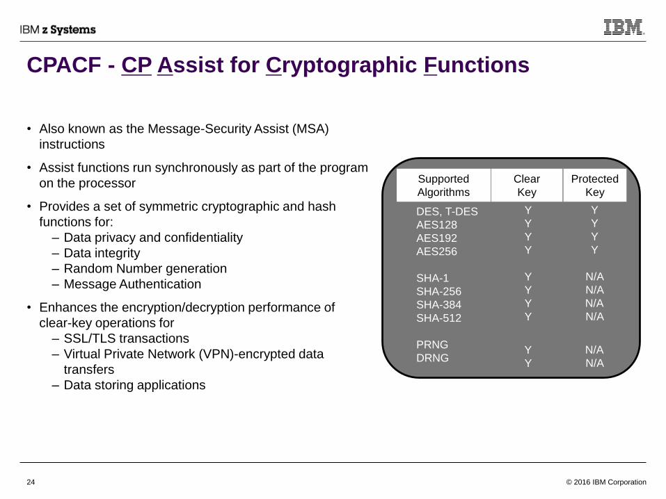
CPACF - CP Assist for Cryptographic Functions
• Also known as the Message-Security Assist (MSA)
instructions
• Assist functions run synchronously as part of the program
on the processor
• Provides a set of symmetric cryptographic and hash
functions for:
– Data privacy and confidentiality
– Data integrity
– Random Number generation
– Message Authentication
• Enhances the encryption/decryption performance of
clear-key operations for
– SSL/TLS transactions
– Virtual Private Network (VPN)-encrypted data
transfers
– Data storing applications
DES, T-DES
AES128
AES192
AES256
SHA-1
SHA-256
SHA-384
SHA-512
PRNG
DRNG
Y
Y
Y
Y
Y
Y
Y
Y
Y
Y
Y
Y
Y
Y
N/A
N/A
N/A
N/A
N/A
N/A
Supported
Algorithms
Clear
Key
Protected
Key
© 2016 IBM Corporation25
Instructions of Interest
We will discuss some of the instructions in z/Architecture and their handling that might be of general
interest:
– Simple instructions, including descriptions of some interesting ones
– Special Storage-to-Storage instructions
– MOVE LONG instructions
– High Word instructions
– Conditional instructions
– EXECUTE instructions
– BRANCH PREDICTION PRELOAD instructions
– DATA PREFETCH instructions
– NEXT INSTRUCTION ACCESS INTENT instruction
– Atomic and locking instructions
And a few architecture features:
– Hardware Transactional Execution
– Vector (SIMD) instructions
And some storage usage model highlights

© 2016 IBM Corporation26
Simple Instructions
• Simple instructions– Fixed-point results are bypassed into the next dependent fixed-point instruction if the instructions are in the same
side of the issue queue; otherwise, there will be at least a one-cycle delay
– An instruction dependent on a storage operand will need to wait for 4 cycles if the operand is in the L1 data cache
– An operand written by a store instruction to a storage address followed by a load instruction of the same address will
require at least 2 to 4 cycles to be bypassed as cache data
– Floating-point instructions are generally pipelined; but can be of different latencies. The design forwards dependent
data as soon as it is available
– Non-floating point vector (SIMD) instructions (in z13) have shorter latencies than floating point ones
• SIMD results are also bypassed when available
• Non-destructive instructions– Many instructions of z/Architecture specify just two operands, with one operand doubling as a source and a target
• These Instructions are shorter (in length) and occupy less space in storage
• If both operands are still required after executing an operation, the operand that will be overwritten must first be
copied to another register before these instructions
– Many non-destructive instructions were introduced since z196, such that the register copy operations can be avoided
• Load and Store Reversed instructions– To facilitate conversion between big-endian (BE) and little-endian (LE) formats, a few instructions are provided to
reverse the byte ordering of a data element to/from memory
– Both load and store operations are supported
– 2, 4, 8 byte operands are supported
– MOVE INVERSE (MVCIN) is also available for more than 8 bytes storage to storage data swap
• It is implemented in millicode doing a byte-by-byte copy
© 2016 IBM Corporation27
Special Storage-to-Storage Instructions
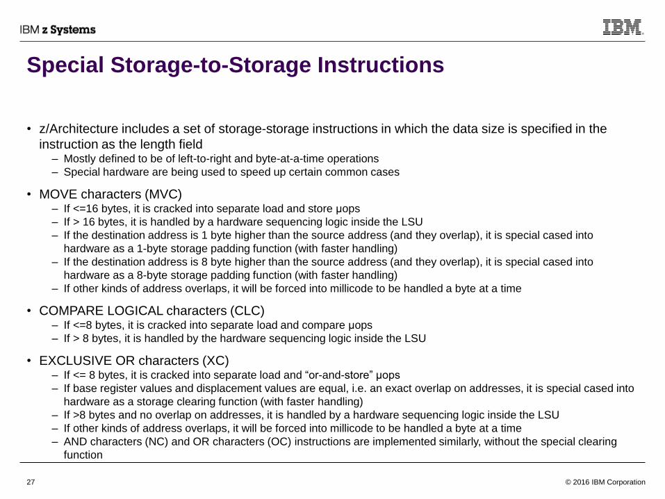
• z/Architecture includes a set of storage-storage instructions in which the data size is specified in the
instruction as the length field– Mostly defined to be of left-to-right and byte-at-a-time operations
– Special hardware are being used to speed up certain common cases
• MOVE characters (MVC)– If <=16 bytes, it is cracked into separate load and store μops
– If > 16 bytes, it is handled by a hardware sequencing logic inside the LSU
– If the destination address is 1 byte higher than the source address (and they overlap), it is special cased into
hardware as a 1-byte storage padding function (with faster handling)
– If the destination address is 8 byte higher than the source address (and they overlap), it is special cased into
hardware as a 8-byte storage padding function (with faster handling)
– If other kinds of address overlaps, it will be forced into millicode to be handled a byte at a time
• COMPARE LOGICAL characters (CLC)– If <=8 bytes, it is cracked into separate load and compare μops
– If > 8 bytes, it is handled by the hardware sequencing logic inside the LSU
• EXCLUSIVE OR characters (XC)– If <= 8 bytes, it is cracked into separate load and “or-and-store” μops
– If base register values and displacement values are equal, i.e. an exact overlap on addresses, it is special cased into
hardware as a storage clearing function (with faster handling)
– If >8 bytes and no overlap on addresses, it is handled by a hardware sequencing logic inside the LSU
– If other kinds of address overlaps, it will be forced into millicode to be handled a byte at a time
– AND characters (NC) and OR characters (OC) instructions are implemented similarly, without the special clearing
function

© 2016 IBM Corporation28
MOVE LONG Instructions
• MOVE LONG instructions (MVCL*)– MOVE LONG instructions can copy a large amount of data from one storage location to another
– A special function can also be used to pad storage
– It is implemented in millicode
• A special engine is built per CP chip for aligned copying or padding functions at a page granularity
– The page aligned copying or padding will be done near memory, instead of through caches, if• Not executed inside a transaction
• Padding character specified is neither X’B1’ nor X’B8’
• A preceding NIAI instruction does not indicate (the storage data will be used subsequently) otherwise
• The operands must not have an access exception
• Length >= 4K byte
• For moves: source and destination addresses are both 4K byte aligned
• For padding: destination address is 4K byte aligned
– Otherwise, the move process will operate through the caches (L1, L2…)
– Note that the evaluation is revised every unit-of-op– For padding, even if starting address is not aligned, millicode will pad (in cache) to 4K boundary, then use near-
memory pad engine for the next aligned 4K; until the remaining length is less than 4K then padding will be done
in cache again
• Near-Memory engine usage is best when the amount of data involved is large; and the target memory is
not to be immediately consumed in subsequent processes– Since the special engine is shared within a CP chip, contention among processors is possible and is handled
transparently by the millicode routine

© 2016 IBM Corporation29
High Word Instructions
• Provided since z196
• High words of GRs are made independently accessible from the low words of GRs
• Software can use up to 32 word GRs, (previous) 16 double-word GRs, or combination of word and
double-word GRs
• For dependencies (i.e. address-generation interlocks), the high-words are treated separately from the
low-words
• Intended to provide register-constraint relief for compilers
• Various types of operations are supported
– Add, subtract, compare, rotate, load, store, branch-on-count
0
1
15
+

© 2016 IBM Corporation30
Conditional Instructions
• In many applications (for instance, sorting algorithms), conditional-
branch outcomes are highly data dependent and thus
unpredictable– A mispredicted branch can result in a pipeline flush, and may incur many
cycles of branch correction penalty
• A limited set of load/store instructions are provided (since z196)
where the execution is predicated on the condition code– Highly unpredictable branches can be replaced with conditional
instructions
• In the example, the old code shows a COMPARE register
instruction (CR) followed by a BRANCH ON CONDITION
instruction (BRNE for BC), and a LOAD instruction (L) that may or
may not be executed depending on the outcome of the branch
• The new code sequence replaces the branch and load instructions
with a LOAD ON CONDITION (LOC) instruction– It is cracked into a load from storage, and a conditional select μop
– The conditional select μop uses the condition code to select between
the original register value and the new value from storage
– This sequence now avoids potential branch wrong flushes
NOTE: Access exception may be reported whether the storage content is
effectively accessed or not
Old Code
CR R1,R3
BRNE skip
L R4,(addressX)
skip AR R4,R3
..
New Code
CR R1,R3
LOC R4,(addressX), b'0111'
AR R4,R3
..
*Pseudo-code for illustration only

© 2016 IBM Corporation31
EXECUTE Instructions
• “Execute” instruction is commonly used* for storage related
instruction (e.g. MVC, CLC mentioned before) where the length
field (specifying the number of bytes) can be substituted by the
content of a general purpose register (GR) without actually
modifying the instruction in memory (and without explicit branch to
or from the ‘target’ instruction
• “Execute” is handled by the processor like a branch– The processor will jump to the target of the execute instruction as a
branch target, and fetch it
– Decode and execute the target instruction; (modify as needed)
– Then immediately return back to the subsequent instruction after the
execute (except when the target is a taken branch itself)
– This “implied” branch handling is supported by the branch prediction
logic to reduce the overall processing delay
• Certain pipeline delay is required between the reading of the GR
and the “modification” of the target instruction– The delay is reduced in z13 for a selected group of instructions: MVC,
CLC, and TRANSLATE AND TEST (TRT)
• The alternative of using a branch table is generally not preferred
due to its potential inaccuracy (i.e. when the length is mostly
random during run-time)
Example where MVC’s length is
dependent on compare of R1 and
R3:
LHI R4,x'1'
LHI R5,x'2'
CR R1,R3
LOCR R4,R5,b'1000'
EX R4,move
..
move MVC 0(length,R13),0(R14)
*Pseudo-code for illustration
only
*other tricky EXECUTE usages not discussed here;
e.g. in modifying register ranges, lengths of operand 1/2,
branch masks
© 2016 IBM Corporation32
BRANCH PREDICTION PRELOAD Instructions
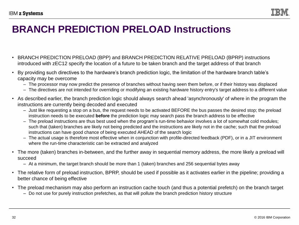
• BRANCH PREDICTION PRELOAD (BPP) and BRANCH PREDICTION RELATIVE PRELOAD (BPRP) instructions
introduced with zEC12 specify the location of a future to be taken branch and the target address of that branch
• By providing such directives to the hardware’s branch prediction logic, the limitation of the hardware branch table’s
capacity may be overcome – The processor may now predict the presence of branches without having seen them before, or if their history was displaced
– The directives are not intended for overriding or modifying an existing hardware history entry's target address to a different value
• As described earlier, the branch prediction logic should always search ahead 'asynchronously' of where in the program the
instructions are currently being decoded and executed– Just like requesting a stop on a bus, the request needs to be activated BEFORE the bus passes the desired stop; the preload
instruction needs to be executed before the prediction logic may search pass the branch address to be effective
– The preload instructions are thus best used when the program’s run-time behavior involves a lot of somewhat cold modules;
such that (taken) branches are likely not being predicted and the instructions are likely not in the cache; such that the preload
instructions can have good chance of being executed AHEAD of the search logic
– The actual usage is therefore most effective when in conjunction with profile-directed feedback (PDF), or in a JIT environment
where the run-time characteristic can be extracted and analyzed
• The more (taken) branches in-between, and the further away in sequential memory address, the more likely a preload will
succeed– At a minimum, the target branch should be more than 1 (taken) branches and 256 sequential bytes away
• The relative form of preload instruction, BPRP, should be used if possible as it activates earlier in the pipeline; providing a
better chance of being effective
• The preload mechanism may also perform an instruction cache touch (and thus a potential prefetch) on the branch target– Do not use for purely instruction prefetches, as that will pollute the branch prediction history structure

© 2016 IBM Corporation33
PREFETCH DATA Instructions
• Started with z10, PREFETCH DATA (PFD) and PREFETCH DATA RELATIVE LONG (PFDRL) instructions were
introduced to enable program code a way to manipulate the local data cache
• The provided prefetch function allows code to acquire a cache line in a correct cache state (for read or for write) ahead of
the actual load/store instructions that will access the data– Note: prefetching a cache line that is contested among multiple processors is usually a bad idea
• These “prefetch” instructions not only allow operand data prefetching, they also provide a way to release a local cache
line’s ownership (or also known as untouch)– The untouch function is to allow software code to proactively release (or invalidate) its ownership (from the processor that it is
running on) of a specified cache line
– The intention is that, when another processor accesses this same cache line some time later, the shared cache (e.g. the L3) will
not need to spend time in removing the line from this processor before granting ownership to this other processor
• These directives should be used carefully, and some experimentation may be required to yield desired performance effect
– Prefetch function can be redundant with given hardware capabilities• The out-of-order pipeline incurs “baseline” prefetching
• The stride-prefetch engine also prefetches cache lines based on fetching patterns and miss history
• The L4 cache does limited prefetch functions from memory based on certain miss criteria
• Prefetch can hurt if the cache line is contested with other processors
– Demote function can be tricky to use• If it is a highly contested cache line, demote operation might hurt (by adding more related operations to the system)
• If the cache line is cold, it might not matter
• In general, the demote function (code 6) is preferred to the untouch function (code 7) since it usually incurs less overhead
• NOTE: EXTRACT CPU ATTRIBUTE (ECAG) instruction should be used, instead of hardcoding any cache-related
attributes, to minimize the chance of observing adverse effects on different hardware models
© 2016 IBM Corporation34
NEXT INSTRUCTION ACCESS INTENT (NIAI) Instruction
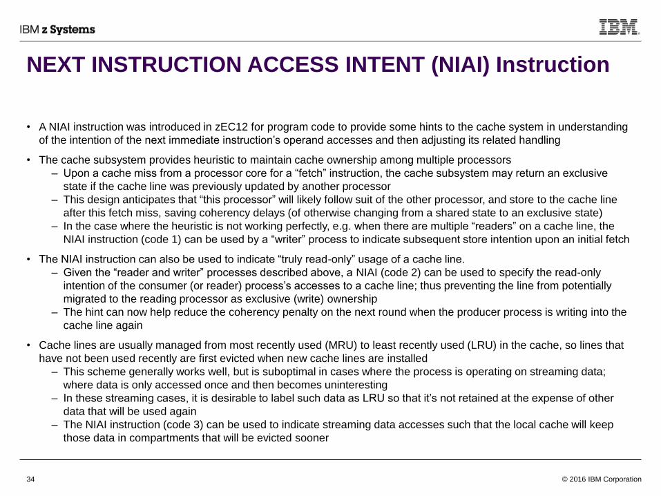
• A NIAI instruction was introduced in zEC12 for program code to provide some hints to the cache system in understanding
of the intention of the next immediate instruction’s operand accesses and then adjusting its related handling
• The cache subsystem provides heuristic to maintain cache ownership among multiple processors
– Upon a cache miss from a processor core for a “fetch” instruction, the cache subsystem may return an exclusive
state if the cache line was previously updated by another processor
– This design anticipates that “this processor” will likely follow suit of the other processor, and store to the cache line
after this fetch miss, saving coherency delays (of otherwise changing from a shared state to an exclusive state)
– In the case where the heuristic is not working perfectly, e.g. when there are multiple “readers” on a cache line, the
NIAI instruction (code 1) can be used by a “writer” process to indicate subsequent store intention upon an initial fetch
• The NIAI instruction can also be used to indicate “truly read-only” usage of a cache line.
– Given the “reader and writer” processes described above, a NIAI (code 2) can be used to specify the read-only
intention of the consumer (or reader) process’s accesses to a cache line; thus preventing the line from potentially
migrated to the reading processor as exclusive (write) ownership
– The hint can now help reduce the coherency penalty on the next round when the producer process is writing into the
cache line again
• Cache lines are usually managed from most recently used (MRU) to least recently used (LRU) in the cache, so lines that
have not been used recently are first evicted when new cache lines are installed
– This scheme generally works well, but is suboptimal in cases where the process is operating on streaming data;
where data is only accessed once and then becomes uninteresting
– In these streaming cases, it is desirable to label such data as LRU so that it’s not retained at the expense of other
data that will be used again
– The NIAI instruction (code 3) can be used to indicate streaming data accesses such that the local cache will keep
those data in compartments that will be evicted sooner

© 2016 IBM Corporation35
Atomic and Locking Instructions
• z/Architecture provides a set of instructions that can be used for atomic operations– e.g. TEST AND SET (TS), COMPARE AND SWAP (CS) that check a value in storage and then conditionally updates
the storage value; such that the fetch and the store are observed to be atomic
• A set of instructions is added since z196 to provide more functionality– Load and “arithmetic” instructions for unconditional updates of storage values
• (Old) storage location value loaded into GR
• Arithmetic or logical operation (add, and, xor, or) result overwrites value at storage location
• Best for unconditionally updating global information, like a counter or a flag
– Interlocked storage updates with an immediate operand are also supported
• Supported operations include add, and, xor and or
– LOAD PAIR DISJOINT (LPD, LPDG)
• Load from two different storage locations into GR N, N+1
• Condition code indicates whether the fetches were atomic
• Hint: for software locks, if the lock is likely concurrently used by multiple processors (i.e. often contested),
the following sequence is recommended– It is more desirable to test the lock value before using atomic instruction (e.g. CS) to set the lock
LHI R2, 1 ; value to set lock
LOOP LT R1, lock ; load from memory and test value; always test first
JNZ LOOP ; repeat if non-zero
CS R1, R2, lock ; set lock if lock was empty
JNE LOOP ; retry if lock became set
*Pseudo-code for illustration only

© 2016 IBM Corporation36
Hardware Transactional Memory
Beginning in zEC12, z/Architecture supports hardware transactional (memory) execution through the
Transaction execution facility– A group of instructions can be observed to be performed with atomicity, or not done at all (aborted)
– Non-transactional stores are allowed within a transaction
– A form of constrained transaction (transaction with restrictions) is also supported that the hardware will automatically
retry the transaction if it aborts/fails; until the transaction is successful
– Optional detail debug data can be provided
Transaction usage is not advisable if the contention of used storage is already high– Likely end up wasting CPU cycles if the transaction keeps aborting due to real-time cross-CPUs memory access
contentions
– Aborts are expensive (>200 cycles); and worse if abort debug information is requested
Hint: compute complex results outside of a transaction, then use transaction with only a small number of
instructions to check data, and then store the results away
Access (fetch) footprint* is limited by L2 associativity and size– Around 1 Mbyte in zEC12, and 2 Mbyte in z13
Update (store) footprint* is limited by L2 associativity and size of an internal store transaction buffer– That can contain up to 64 blocks of 128-byte (storage aligned) data changed within a transaction
– The L1 data cache is updated upon store instruction processing within a transaction, but L2 is deferred until
transaction completes
Note: Access footprint may be counted for fetches done through mispredicted branches; footprint limitations are shared by
the 2 threads when SMT2 is enabled (in z13) such that effective footprint may be smaller than when one thread is running
© 2016 IBM Corporation37
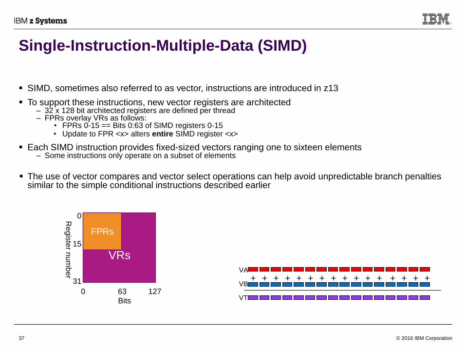
Single-Instruction-Multiple-Data (SIMD)
SIMD, sometimes also referred to as vector, instructions are introduced in z13
To support these instructions, new vector registers are architected– 32 x 128 bit architected registers are defined per thread– FPRs overlay VRs as follows:
• FPRs 0-15 == Bits 0:63 of SIMD registers 0-15• Update to FPR <x> alters entire SIMD register <x>
Each SIMD instruction provides fixed-sized vectors ranging one to sixteen elements– Some instructions only operate on a subset of elements
The use of vector compares and vector select operations can help avoid unpredictable branch penalties similar to the simple conditional instructions described earlier
+ + + ++ + + + + + + ++ + + +VA
VB
VT
VRs
0
15
31
FPRs
0 63 127
Bits
Regis
ter n
um
ber
© 2016 IBM Corporation38
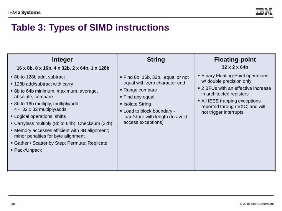
Table 3: Types of SIMD instructions
Integer
16 x 8b, 8 x 16b, 4 x 32b, 2 x 64b, 1 x 128b
8b to 128b add, subtract
128b add/subtract with carry
8b to 64b minimum, maximum, average,
absolute, compare
8b to 16b multiply, multiply/add
4 - 32 x 32 multiply/adds
Logical operations, shifts
Carryless multiply (8b to 64b), Checksum (32b)
Memory accesses efficient with 8B alignment;
minor penalties for byte alignment
Gather / Scatter by Step; Permute; Replicate
Pack/Unpack
String
Find 8b, 16b, 32b, equal or not
equal with zero character end
Range compare
Find any equal
Isolate String
Load to block boundary -
load/store with length (to avoid
access exceptions)
Floating-point 32 x 2 x 64b
Binary Floating-Point operations
w/ double precision only
2 BFUs with an effective increase
in architected registers
All IEEE trapping exceptions
reported through VXC; and will
not trigger interrupts

© 2016 IBM Corporation39
Uniprocessor Storage Consistency
Uniprocessor view of storage consistency
– General rules (important for full software compatibility):
• Program must behave as if executed serially
• Each instruction can use all results of previous instructions
– Operand accesses must be observed to be done in program order
• Store / fetch conflicts recognized by real* address
• Most operands processed left to right
• Fixed-point decimal operands processed right to left
• Storage-storage (SS) instructions are observed to operate in a byte-by-byte fashion
– Instruction pre-fetches may be observed
• Must still detect store updates / instruction fetch conflicts; where detection is on logical* address
only
• Instructions executed must reflect prior stores
• Serialization can add further restrictions (next page)
*Logical address
– What program specifies
– May be virtual or real, depending on program status word (PSW)
• unless explicitly overridden by the instruction itself (see detail instruction definitions)
*Real address
– Result of dynamic address translation (DAT) or the logical address when DAT is off
– Subject to prefixing

© 2016 IBM Corporation40
Multiprocessor Storage Consistency
Must be able to define consistent ordering of accesses– “as seen by this and other processors"
– Some instruction operations are allowed to have ambiguous results (See the section “Storage-Operand Consistency”
in the z/Architecture Principles of Operation for details)
Operand fetches and stores must appear to occur in proper order
All processors must obey uniprocessor rules– Although the processor is designed to do things out-of-order, the observed results must be consistent
– The processor has states and checking in place, such that when the out-of-order accesses might be observed to be
inconsistent, the pipeline will flush and retry the operations; possibly in a “safer” (slower) mode
Operand accesses must be DW-consistent– No "score-boarding" should be observed
– e.g. DW consistency is maintained for LOAD MULTIPLE (LM) when the loads are expanded into individual GR writing
operations
Instruction fetches are generally allowed in any sequence
CPU1 CPU2
Store R1,AA Store R1,BB
Load R2,AA Load R2,BB
Load R3,BB Load R3,AA
As an example, if both final Load instructions get “old” (pre-store) values : Violation!

© 2016 IBM Corporation41
Serialization
z/Architecture defines a set of situations in which additional restrictions are placed on the storage access
sequence
Defined as “A serialization operation consists in completing all conceptually previous storage accesses
and related reference-bit and change-bit settings by the CPU, as observed by other CPUs and by the
channel subsystem, before the conceptually subsequent storage accesses and related reference-bit and
change-bit settings occur”
Defined for specific points in instruction stream
– Usually "before and after" specific opcodes
– Includes Instruction fetches as well as operand accesses
– Exception: Instruction fetch for the serializing instruction itself
CPU 1 CPU 2
MVI A,X’00’ G CLI A,X’00’
BCR 14,0 BNE G
The BCR 14,0 instruction executed by CPU 1 is a serializing instruction that ensures
that the store by CPU 1 at location A is completed. However, CPU 2 may loop
indefinitely, or until the next interruption on CPU 2, because CPU 2 may already have
fetched from location A for every execution of the CLI instruction. A serializing
instruction must be in the CPU-2 loop to ensure that CPU 2 will again fetch from
location A.

© 2016 IBM Corporation42
General Guidelines
Besides the references mentioned at the end, you might find these other existing documents or presentations useful
– John R. Ehrman's book on Assembler Language Programming for IBM z System Servers
– Dan Greiner has regular presentations of z/Architecture features with SHARE
– Silvia Mueller has a presentation on SIMD usage that is available on z13
Some general recommendations will be provided next, including some that have been mentioned in previous pages
– All descriptions provided are of general guidance only
– It will not be practical to describe all intricate design details within the systems in this document
– There may be counter-examples (usually rare occurrences) that will observe hardware behavior differently than
described; or not adhere to optimization recommendations provided
– Detail instruction by instruction classifications and timings will not be provided in this document
Z processors are designed for processing both cache-intensive and CPU-centric workloads, and are optimized to handle
code that was hand-written from many years ago or was generated from the latest compilers, running in applications,
middleware or operating systems
– General rules that help produce good performance code for modern processor microarchitectures usually apply to z
processors too
– Microprocessor pipeline, branch prediction algorithm, cache subsystem structure and their characteristics will likely
change from generation to generation to obtain better general performance improvements and bigger system
capacity
– Code sequence can be tuned to get more performance by optimizing to a new processor pipeline, or using new
instructions or new architectures
– Performance variations should be expected on highly optimized code that is tuned to a specific processor generation
vs. another generation

© 2016 IBM Corporation43
Branch Related Guidelines
Align frequently called functions to start at storage boundaries for efficient instruction fetching– at least at QuadWord (16-byte) boundary, but potentially even better if at OctWord (32-byte) or cache line boundaries
Rearrange code path around conditional branches such that the not-taken path (i.e. fall-through path) is the most frequent
execution path
Although the branch predictor attempts to predict every cycle, keeping loops to be at least 12 instructions will allow branch
prediction to catch up– if more instructions can be used, branch prediction will be able to stay ahead of instruction fetching
Although z processors do not include a call-return predictor, pairing up calls and returns may facilitate the current design to
work more effectively
Consider inlining subroutines if they are small and used often
Unroll loops to parallelize dependency chains to take maximize the advantage of parallel and out-of-order processing
Use relative branches instead of non-relative (indirect branches) when possible
There is usually advantage of using a branch-on-count or a branch-on-index type instruction versus doing the operations
as individual instructions; due to– Smaller instruction footprint and less hardware overhead
– Branch-on-count and branch-on-index-low-or-equal type instructions are predicted taken whenever the branch prediction logic is
not able to predict its direction ahead of time
Similarly, load-and-test or compare-and-branch type instructions will be better than a pair of individual instructions
Avoid hard-to-predict branches by using conditional instructions– Conditional instruction is usually slower than a correctly predicted branch + load/store instructions; thus "hard-to-predict" is an
important criteria

© 2016 IBM Corporation44
Instruction Selection Guidelines (1)
Register-storage format instruction is often more efficient than a 2-instruction sequence of “load” + “register-register”
operations
Use instruction variants that do not set condition code if available (and when the resulting condition code is not required)
Use instructions of shorter instruction lengths if possible
Base + Index + Displacement form (3-way) address generation used to access storage within an instruction incurs no
additional penalty vs. a 2-way form or a register-based form– Similarly, Base + Index + Displacement form branch target calculation incurs no additional delays vs. a register form; e.g. BC vs.
BCR
– Precompute storage address only if you can use it for branch prediction preloading or operand data prefetching
– However, “Load Address” type instructions will take an extra cycle through the FXU when both base and index registers are not
using GR#0
Understand rotate-then-*-selected-bits instructions, and see if they can be used– The second-operand register is rotated left by a specified amount; then one of four operations (and, xor, or, insert) is performed
using selected bits of the rotated value and the first-operand register
Use compare-and-trap instructions where practical; they are best for null-pointer checking
Take advantage of the additional high-word GRs instead of performing register spill-and-fill through storage– In z13, VRs might also be used
Regular register clearing instructions are fast-pathed in the pipeline; and their results do not use any physical registers
(since zEC12)– EXCLUSIVE OR register (XR, XGR of same register); which sets CC=0
– LOAD HALFWORD IMMEDIATE (LHI, LGHI of immediate value 0), which leaves CC unchanged
– LOAD ADDRESS (LA) where Base, Index, and Displacements are all zero’s
– And, since z13, LOAD ZERO {long}, {extended} (LZDR, LZER)

© 2016 IBM Corporation45
Instruction Selection Guidelines (2)
Use the long-displacement variants, with a 20-bit signed displacement field, that provide a positive or negative
displacement of up to 512K bytes if necessary
A set of instructions (ends with RELATIVE LONG) are provided to operate on data elements where the address of the
memory operand is based on an offset of the program counter rather than an explicitly defined address location. The offset
is defined by an immediate field of the instruction which is sign extended and is aligned as a halfword address when added
to the value of the program counter– Load, store and various kinds of compares are provided
– Such accesses are treated as data accesses (except for EXECUTE RELATIVE LONG), these data elements should not be
placed in the same cache lines as the program instructions to avoid potential cache conflicts
For operations on large amount of memory, e.g., copying or padding storage, consider using instructions that can handle
long operand lengths, e.g., MOVE characters (MVC), instead of doing individual loads or stores
Complex instructions, e.g. COMPRESSION CALL (CMPSC), convert-UTF-UTF instructions, and cryptographic
instructions are usually faster than software routines with the help of the per-core co-processor, especially for large
datasets
For serialization, a BCR 14,0 (supported since z196) is better than BCR 15,0 (which also requires checkpoint
synchronization needed for software checkpoints that might incur additional delays)
For storing clock value, use STOCK CLOCK EXTENDED (STCKE); if uniqueness is not required, use STORE CLOCK
FAST (STCKF)
Use simple “interlocked-access” instructions, e.g. LOAD AND ADD (LAA), OR/AND/XOR immediate (OI, NI, XI), instead of
conditional loops using compare-and-swap type instructions, for any unconditional atomic updates– OI, NI, XI (and their long displacement analogues, OIY, NIY, XIY) were used in examples that did not interlock in earlier
architecture; these instructions are now interlocking since z196
© 2016 IBM Corporation46
Instruction Scheduling Guidelines
Optimizing instruction grouping efficiency might yield better performance – Arrange code such that 3 instructions that can be grouped together to optimize dispatch bandwidth
– Instruction clump formation (instruction storage alignment) affects how instructions are fetched from the instruction cache, and
may affect grouping effectiveness
– Branch instruction ends a group in z196; but after zEC12, it ends only if it is predicted taken or if second in the group
Execution results can be bypassed without any additional latency to a dependent instructions if the sourcing and receiving
instructions are on the FXUs (FXUa, but not FXUb in z13) of the same side of the issue queue– This can be arranged by having the instructions placed consecutively, and thus usually in the same group (and the same side)
Floating-point (FP) operations– Mixed mode FP (e.g. short->long, long->short, hex->bin, bin->hex) operations should be avoided; results are typically not
bypassed, and could cost pipeline rejects or flushes
– In z13, the simpler mapper tracker design used for VRs (and FPRs) can lead to false dependencies in single precision FP
operations; where possible, double precision FP operations should be used
– In z13, execution functions are evenly distributed (symmetric) among the 2 sides of the issue queue, scheduling that enable
parallel processing among the 2 different sides can potentially achieve better performance
• For reference, in z196 and zEC12, floating-point unit and fixed-point multiply engine are only provided on one side of the
issue queue
• For z13, FP results bypassing capability are symmetric among FP operations from the two issue queue sides
Software directives like branch prediction preload and prefetch data instructions should be placed as far back from actual
usage as possible to be effective– As usage of these instructions might have adverse effects of increasing overall code size, they are best used by applying
insights based on run-time profiles such that “blind” insertions can be avoided
© 2016 IBM Corporation47
Cache Related Guidelines (1)
Avoid instructions (executable code) and operand data (working storage or stack storage) in the same cache lines; which
can be costly due to moving cache lines between the separated (split) local caches (instruction/data L1/L2)– Since both instruction and operand accesses can be predictive in nature; if they can be located further apart, the possibility of
leading to unintended cache transfer delays can be reduced
– The target operand of an EXECUTE-type instruction is treated as an instruction fetch (not data operand); and should be located
as part of the instruction cache lines
– Self-modifying code (or store-into-instruction-stream) is supported in hardware functionally, but in general, the sequence can
become costly due to out-of-order pipelining and movement of cache lines
– Pay attention to local (static) save areas and macro expansions with in-line storage parameters, especially in older Assembler
code, to avoid unintended sharing
Instruction Cache optimization– Minimize the number of cache lines needed through the most frequent execution path
• Separate out frequently and infrequently used code to different storage areas can improve both cache and translation-
lookaside-buffer (TLB) efficiency
– Software hints, e.g. prefetch data and branch prediction preload instructions, should not be added blindly
• Unnecessary hints may increase instruction cache footprint and instruction processing delay
• Branch prediction preload instruction also does instruction cache touch (as a way of prefetching)
– Unrolling and inlining should be done to improve potential processing parallelism, but should be targeted with a reasonable
resulting loop size; i.e. aim for maximum processing with minimal loop size

© 2016 IBM Corporation48
Cache Related Guidelines (2)
Data Cache optimization– Don’t mix multiple distinct shared writeable data in the same cache line; to avoid potential tug-of-war among multiple processors
• Avoid putting multiple shard (and contested) locks in the same cache line
– Avoid using any storage element as a running variable that will get fetched and updated many times in close proximity
• Consider using a general register instead
• Similarly, avoid spill and fill through storage within a short number of instructions
– NIAI may be used to provide hints to the hardware about intentions of storage accesses to avoid delays from potential cache
state changes
– Data Prefetch instructions with both prefetch and untouch functions are provided
• For cache lines that are contested among many processors, it might not be desirable to prefetch the cache line ahead of
time; which will add unnecessarily data movement in the system causing extra delays
– L1 access pipeline (from issue of data fetch to issue of dependent instruction) is currently at 4 cycles, scheduling non-
dependent operations in-between to allow maximum parallel processing
– Although the designs have ways to detect store-to-load dependencies and provide as much bypass capability as possible, the
mechanism are improving every generation but is not perfect, minimizing storage access dependencies will usually yield better
performance
• In general, simple store and load instructions are handled well while more complicated instructions or address overlaps
may observe more pipeline rejects

© 2016 IBM Corporation49
References
1. “z/Architecture: Principles of operation,” Int. Bus. Mach. (IBM) Corp., Armonk, NY, USA, Order No. SA22-7832-10, Feb. 2015.
[Online].
2. M. Farrell et al, “Millicode in an IBM zSeries processor,” IBM J. Res. & Dev., vol. 48, no. 3/4, pp. 425–434, 2004.
3. C.F. Webb, ‘‘IBM z10: The Next-Generation Mainframe Microprocessor,’’ IEEE Micro, vol. 28, no. 2, 2008, pp. 19-29.
4. C Shum, “Design and microarchitecture of the IBM System z10 microprocessor,” IBM J. Res.& Dev., vol. 53, no. 1, 2009, pp. 1.1-
1.12.
5. Brian W. Curran et al, “The zEnterprise 196 System and Microprocessor,” IEEE Micro, vol. 31, no. 2, 2011, pp. 26-40.
6. F. Busaba et al, “IBM zEnterprise 196 microprocessor and cache subsystem,” IBM J. Res.& Dev., vol. 56, no. 1/2, pp. 1:1–1:12,
Jan./Feb. 2012.
7. K. Shum et al, “IBM zEC12: The third-generation high-frequency mainframe microprocessor,” IEEE Micro, vol. 33, no. 2, pp 38–47,
Mar./Apr. 2013.
8. Bonanno et al, “Two Level Bulk Preload Branch Prediction”, HPCA, 2013
9. C. Jacobi et al, “Transactional Memory Architecture and Implementation for IBM System z,” IEEE/ACM Symposium on
Microarchitecture (MICRO), 2012.
10. B. Curran et al, “The IBM z13 multithreaded microprocessor,” IBM J. Res. & Dev., vol. 59, no. 4/5, pp. 1:1–1:13, 2015.
11. E. M. Schwarz et al, “The SIMD accelerator for business analytics on the IBM z13,” IBM J. Res. & Dev., vol. 59, no. 4/5, pp. 2:1–
2:16, 2015.
12. B. Prasky et al, “Software can Provide Information Directly to the System z Microprocessor”, IBM Systems Magazine, May 2014
13. C. Walters et al, "The IBM z13 processor cache subsystem", IBM J. Res. & Dev., vol. 50, no. 4/5, pp. 3:1-3:14, 2015.

© 2014 IBM Corporation
50
All statements regarding IBM’s future direction and intent are subject to
change or withdrawal without notice, and represent goals and objectives only.
© 2015 IBM Corporation 50
THANK YOUSuggestions, questions, comments:
https://www.linkedin.com/in/ckevinshum