ibm rational open day€¦ · ibm rational open day corso archimate ... table of contents...
TRANSCRIPT
1
IBM Rational Open Day
Corso ArchiMate® plug-in and IBM Rational
System Architect Introduction
2
Table of Contents Introduction .......................................................................................................................................... 3
Objectives ............................................................................................................................................. 5
Scenario ................................................................................................................................................ 5
ArchiMate Implementation within Rational System Architect .............................................................. 5
Lab – ArchiMate plug-in for Rational System Architect ........................................................................ 7
1.1 Setup ....................................................................................................................................... 7
1.2 Introducing the Working Environment .................................................................................. 10
1.3 Framework Browser .............................................................................................................. 15
1.4 Notation and Methodology Support...................................................................................... 19
1.5 Representational Consistency ............................................................................................... 32
1.6 Method Wizard ...................................................................................................................... 40
1.7 Impact Analysis (Heatmaps) .................................................................................................. 47
1.8 Explorer Diagram ................................................................................................................... 57
1.9 Report Generator .................................................................................................................. 62
1.10 (Optional) Advanced Search ................................................................................................ 65

3
Introduction
Rational System Architect IBM Rational System Architect™ is the leading enterprise architecture tool for developing a complete end-to-end blueprint of an organization. The System Architect™ toolset allows decision makers, architects and stakeholders to gather enterprise wide information and collaborate on models of the enterprise to understand the impact of change required by business initiatives. With the encouragement of IBM, Corso has created a toolkit that supports version 2.1 of ArchiMate® within System Architect™. The combination of System Architect™ and ArchiMate® provides a rich, yet easy-to-use set of capabilities specifically targeted at enterprise architects and business analysts intent on documenting and making decisions based upon the ArchiMate® approach.
Enterprise architecture modeling support
IBM® Rational® System Architect enables you to visualize, analyze, and communicate the enterprise
architecture of your organization.
Visualize
Rational System Architect provides a rich set of modeling capabilities that enable you to visualize an enterprise
architecture. Modeling capabilities include diagram types and definition types that enable you to model the
who, what, where, when, why, and how of the business, through all stages of understanding, including
contextual, conceptual, logical, and physical modeling, and implementation of working systems supporting the
enterprise. Rational System Architect provides a suite of business modeling diagramming (including business
process models, organizational hierarchy charts, functional models, business concept diagrams, and so forth),
UML modeling for application and system development, and relational data modeling (including logical and
physical data models and schema generation/reverse engineering).
Analyze
Rational System Architect provides capabilities to analyze the enterprise architecture models.
Analytics -- The analytic definition type provides a user interface to analytic macros that you can build to run metrics algorithms against models, and visually display indicators next to symbols on diagrams reflecting the output of the algorithms. For example, you might run an analytic to show costs of business processes, and display gauges next to processes on a business process diagram, with the indicator on the gauge reflecting the cost of the particular process.
Explorer Diagram -- the Explorer diagram enables you to visually show relationships of model artifacts in the repository, based on reports that you write using the reporting system. The Explorer diagram enables you to create "what if" analysis on the models. For example, you can visually see what business processes are affected if a hardware server is brought down for repairs.
Business Process Simulation --Simulator II is a paid add-on to Rational System Architect that enables you to simulate business process diagrams -- BPMN Process diagrams, IDEF3 Process Flow diagrams, or Process Charts.
4
Communicate
Rational System Architect enables you to communicate your enterprise architecture to a wide audience
through the use of these features:
Reporting System -- The reporting system provides pre-written reports and enables you to build your own reports on model information, and print formatted reports or publish the output to html/xml.
Word Reporting -- The Word Interface enables you to choose from prebuilt reports and generate the output to Word.
HTML Generator -- The HTML Generator enables you to generate models to a website output.
Information Web Publisher -- This is a paid add-on to Rational System Architect that combines the power of the reporting system with HTML generation, enabling you to produce very sophisticated websites of enterprise architecture information, with output that can be tailored to different audiences.
ArchiMate ArchiMate offers a common language for describing the construction and operation of business processes, organizational structures, information flows, IT systems, and technical infrastructure. This insight helps the different stakeholders to design, assess, and communicate the consequences of decisions and changes within and between these business domains. An architecture framework is used to structure the concepts and relationships of the ArchiMate language. It divides the enterprise architecture into a business, application and technology layer. In each layer, three aspects are considered: active elements that exhibit behavior (e.g. Process and Function), an internal structure and elements that define use or communicate information.
One of the objectives of the ArchiMate language is to define the relationships between concepts in different
architecture domains. The concepts of this language therefore hold the middle between the detailed concepts,
that are used for modeling individual domains, for example, the UML for modeling software products and
BPMN which is used for business process modeling.
ArchiMate offers a modeling language to create fully integrated models of the organization’s enterprise
architecture, the motivation for the enterprise architecture, and the programs, projects and migration paths to
implement this enterprise architecture. Using an architecture framework will speed up and simplify
architecture development, and communication with non-architects, ensuring more complete coverage and
understanding of the designed solution. The additional understanding across the enterprise enables faster
response to changing business needs.
ArchiMate offers a three-layered view
• The Business layer is about business processes, services, functions and events of business units. This layer "offers products and services to external customers, which are realized in the organization by business processes performed by business actors and roles".
• The Application layer about software applications that "support the components in the business with application services".
• The Technology layer deals "with the hardware and communication infrastructure to support the Application Layer. This layer offers infrastructural services needed to run applications, realized by computer and communication hardware and system software".
• ArchiMate also has extensions to the core, consisting of Motivation and Implementation and Migration extensions
5
Each layer "aims to provide a natural way to look at service-oriented models. Each layer is self contained
despite being a component of the integrated model, and caters to one or more architecture domains".
Objectives
Understand the implementation of the ArchiMate Framework within Rational System Architect
Get hands on with:
Creating diagrams (views) and manipulating model content within them
Using the Method Wizard feature to reduce time in understanding and building relationships between
ArchiMate concepts.
Assessing the consequences of decisions and the impact of change using heatmaps
Scenario
In this Open Day we will use a fictitious Insurance company ‘ArchiSurance’ that is looking to model its enterprise architecture as our example. The company has chosen ArchiMate to do this and the Rational System Architect tool. The System Architect™ toolset allows decision makers, architects and stakeholders to gather enterprise wide information and collaborate on models of the enterprise to understand the impact of change required by business initiatives. The company are hoping to be able to view the domain relationships and better understand the linkages and impact of the changes they wish to make, whilst working out migration paths to take them from the As-Is to the To-Be architecture. Stakeholders at all levels in the business can then collaborate about transition plans, work packages and roadmaps for strategy, business capabilities, application components and technology.
ArchiMate Implementation within Rational System Architect
ArchiMate like some other notations specifies model-view behavior where the view is tied to the model; If the
view changes then the model changes, and if the model changes then all of the views which show that part of
the model will similarly change. Thus the model and views are kept ‘in sync’.
This behavior applies to both the definitions and the relationships between them. If the details of a definition
changes then all views are updated. If a relationship between two objects is created then the model and all
views are updated.
In System Architect we can view, create and modify relationships in three ways:
Via definition properties
Via lines on diagrams
Via the matrix editor

6
The implementation supports the full set of ArchiMate model view types, with an out of the box metamodel for ArchiMate® 2.1, that supports the ArchiMate® standards and exploits the features of IBM Rational System Architect™. The plug-in also supports enhanced graphics for the notation, which is scalable, aesthetic shape support, aiding adoption and communication of ArchiMate® to a wider audience.
The first few exercises in the following labs will make use of features in Rational System Architect and the Corso ArchiMate Plug-in that aid in adoption and model construction. The later exercises will concentrate on using the features to interrogate and explore the built model and make decisions based upon the findings.
7
Lab – ArchiMate plug-in for Rational System Architect
1.1 Setup
Logging In
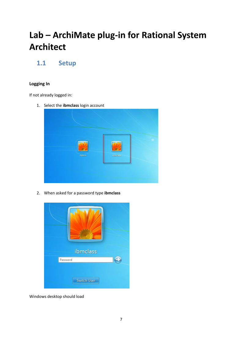
If not already logged in:
1. Select the ibmclass login account
2. When asked for a password type ibmclass
Windows desktop should load
8
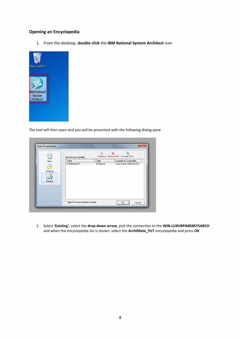
Opening an Encyclopedia
1. From the desktop, double click the IBM Rational System Architect icon
The tool will then open and you will be presented with the following dialog pane
2. Select 'Existing', select the drop down arrow, pick the connection to the WIN-LUKVBPI68S8SYSARCH
and when the encyclopedia list is shown, select the ArchiMate_PoT encyclopedia and press OK

9
3. When asked to select a workspace, select the Current State Architecture workspace from the list and press OK
The encyclopedia will then open
(Any issues at this point then please contact the instructor)
Note: We will take a closer look at workspaces later on
10
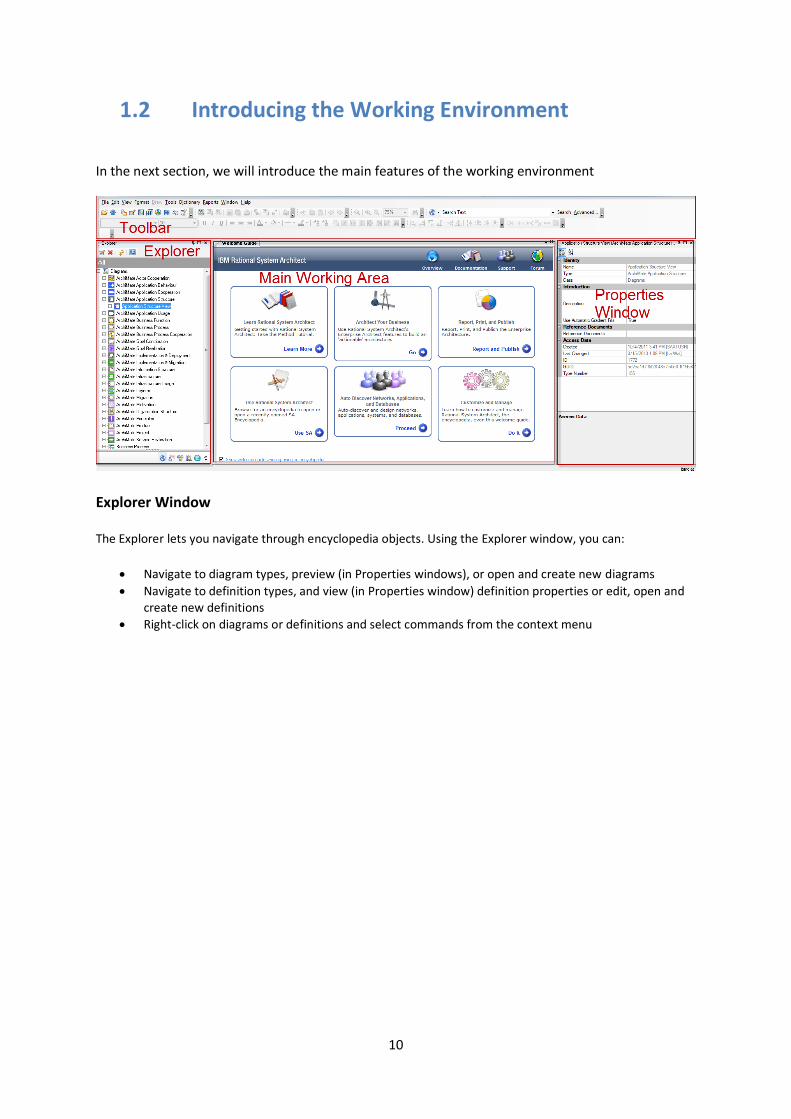
1.2 Introducing the Working Environment
In the next section, we will introduce the main features of the working environment
Explorer Window
The Explorer lets you navigate through encyclopedia objects. Using the Explorer window, you can:
Navigate to diagram types, preview (in Properties windows), or open and create new diagrams
Navigate to definition types, and view (in Properties window) definition properties or edit, open and create new definitions
Right-click on diagrams or definitions and select commands from the context menu

11
Explorer Toolbar
Left to right, the Explorer toolbar buttons perform the following tasks:
Open the selected objects
Delete the selected objects from the encyclopedia
Refresh the current View
Add a new Pane, delete or rename the current Pane
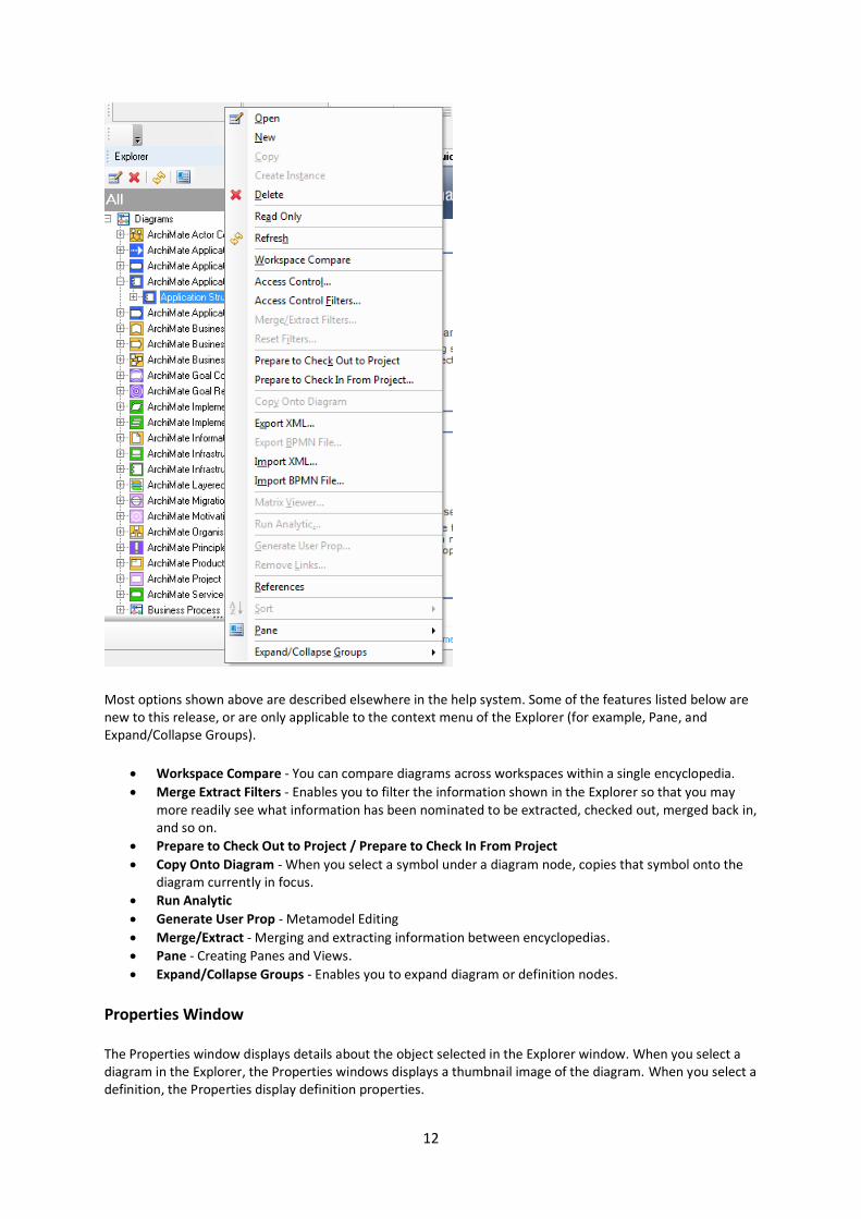
Explorer Context Menu
When you right-mouse click on Diagram, Definition, or other nodes in the Explorer, a set of options are available depending on what you select.
12
Most options shown above are described elsewhere in the help system. Some of the features listed below are new to this release, or are only applicable to the context menu of the Explorer (for example, Pane, and Expand/Collapse Groups).
Workspace Compare - You can compare diagrams across workspaces within a single encyclopedia.
Merge Extract Filters - Enables you to filter the information shown in the Explorer so that you may more readily see what information has been nominated to be extracted, checked out, merged back in, and so on.
Prepare to Check Out to Project / Prepare to Check In From Project
Copy Onto Diagram - When you select a symbol under a diagram node, copies that symbol onto the diagram currently in focus.
Run Analytic
Generate User Prop - Metamodel Editing
Merge/Extract - Merging and extracting information between encyclopedias.
Pane - Creating Panes and Views.
Expand/Collapse Groups - Enables you to expand diagram or definition nodes.
Properties Window
The Properties window displays details about the object selected in the Explorer window. When you select a diagram in the Explorer, the Properties windows displays a thumbnail image of the diagram. When you select a definition, the Properties display definition properties.

13
1. From the toolbar, select the Show Properties Window button
Using the Properties window, you can:
View definition values and properties in a simple grid view
Click the Edit Object link to edit definitions through the standard dialogs
Click the Show Referenced Objects link to list objects referenced by a definition
Display definitions as categorized groups or in alphabetical order
The Matrix Browser Window
The Matrix Browser window displays a categorized view of available matrices. You click on an icon at the bottom of the window to get a list of corresponding matrices, categorized by the methodologies in use. You click on the matrix you wish to run.
Note: The Framework, Reports and other Windows work similar to those described above.
Docking Rational System Architect Windows
1. Select the Show Diagram Preview button from the toolbar
2. Select a diagram from the Explorer
14
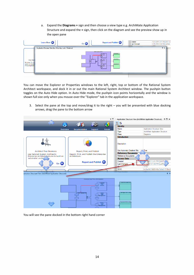
a. Expand the Diagrams + sign and then choose a view type e.g. ArchiMate Application
Structure and expand the + sign, then click on the diagram and see the preview show up in
the open pane
You can move the Explorer or Properties windows to the left, right, top or bottom of the Rational System Architect workspace, and dock it in or out the main Rational System Architect window. The pushpin button toggles on the Auto Hide option. In Auto Hide mode, the pushpin icon points horizontally and the window is shown full size only when you mouse-over the "Explorer" tab in the application workspace.
3. Select the pane at the top and move/drag it to the right – you will be presented with blue docking arrows, drag the pane to the bottom arrow
You will see the pane docked in the bottom right hand corner

15
4. Close both the Diagram Preview and the Properties panes
1.3 Framework Browser
What is the Framework Browser?
The Framework Browser is, in essence, a grid of buttons (cells) arranged in rows and columns. Each button activates one or more browsers that display a focused subset of the diagrams, definitions and matrices. The particular diagrams, definitions and matrices displayed depends on the definition of each cell. More than one browser may launch if the cell contains items with different model perspectives.
The browser of each cell acts in the same way as the main browser. Therefore, all actions that can be performed in the default browser are available to the individual cell browsers.
Using the Framework Browser
The Framework Browser enables you to view and access the models and artifacts you have developed in a System Architect encyclopedia through a framework interface. You can customize the

16
structure of the framework, such as the number and name of columns and rows, pictures that make up the framework, and diagrams and definition types associated with each cell.
You can also create multiple frameworks and specify, using the Framework Editor, which framework comes opens by default for users of the product. For example, using the Framework Browser you can do the following tasks:
1. Select the Show Framework button from the toolbar
2. With the CORSO ArchiMate Framework showing click on the ‘Organization’ cell and see that everything organization related is behind this cell.
3. Navigate the tree of diagrams and definitions associated with this cell by clicking on the + sign to the left to the headings
(You may need to move the explorer box if you cannot see the '+' signs to expand the tree)
4. Click the + sign again to see the instances of the diagram types in the encyclopedia
Open diagrams double-clicking on the instance name. A diagram contains symbols, each of which has an underlying definition.

17
The process of creating and modifying diagrams in Rational System Architect involves creating or opening a diagram of a specific type, drawing symbols and lines on the surface of the diagram, and adding definitions to each of the symbols and lines drawn. Each symbol that you drop on a diagram is considered an instance of the definition. Information added to the Symbol tab belongs to that instance only. The rest of the tabs within the Edit dialog represent the symbol’s definition.
Examples of the symbols can be seen on the diagram
(Optional) - To open the symbol's definition dialog, either double-click on the symbol, right-mouse-click on the symbol and choose Edit from the drop-down list
5. Open definitions directly by clicking the + signs and then double clicking the definition instance that exists
In the dialog that open you can see the properties associated within the definition dialog that opens. Each diagram type, definition type, and symbol type in Rational System Architect has a default set of properties declared for it; you may modify these properties, or add to them, using Rational System Architect’s extensibility mechanism.
6. Open pop-up menus by right-clicking in the browser
18
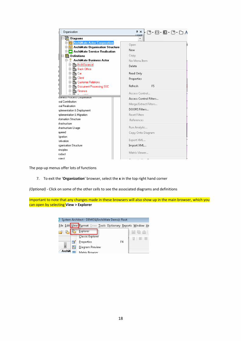
The pop-up menus offer lots of functions
7. To exit the ‘Organization’ browser, select the x in the top right hand corner
(Optional) - Click on some of the other cells to see the associated diagrams and definitions
Important to note that any changes made in these browsers will also show up in the main browser, which you can open by selecting View > Explorer
19
1.4 Notation and Methodology Support
Notation
The ArchiMate metamodel has been faithfully rendered as views, definitions and relationships within System
Architect.
Features
Out of the box metamodel for ArchiMate 2-0 - Providing a completely usable real world representation of the ArchiMate objects and relationships without the need to customize.
Enhanced graphics support for notation - Scalable, aesthetic shape support within System Architect which aids adoption and communication of ArchiMate to a broad audience.
Representational consistency - All models are automatically consistent across the model and coherent throughout the views in the repository.
Method Wizard - The method wizard helps new and experienced architects alike to understand and build relationships between concepts. The wizard reduces the effort in adopting ArchiMate® by providing a real-time pragmatic guide through the metamodel.
The Basics
First of all we will look at how you can build the model either through using the model views and drawing,
building from within the definition dialogs themselves or from using matrices to define the
relationships...Whichever way you choose, the other methods are kept in sync
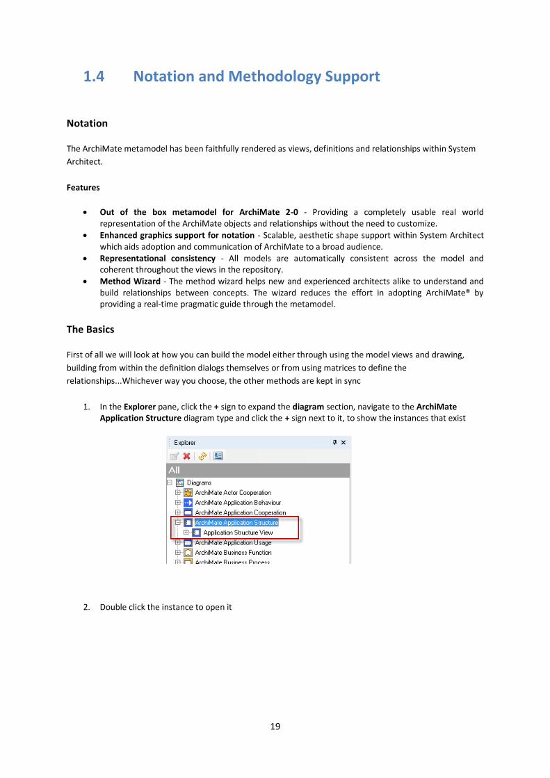
1. In the Explorer pane, click the + sign to expand the diagram section, navigate to the ArchiMate Application Structure diagram type and click the + sign next to it, to show the instances that exist
2. Double click the instance to open it

20
With the diagram open we can see Application Components, Data Objects along with several types of ArchiMate specific relationships. In the symbol toolbar, you can see all of the symbols available to the user, relative to this diagram type
3. On the open diagram, Select the Home and Away Policy administration symbol, by double-clicking it
21
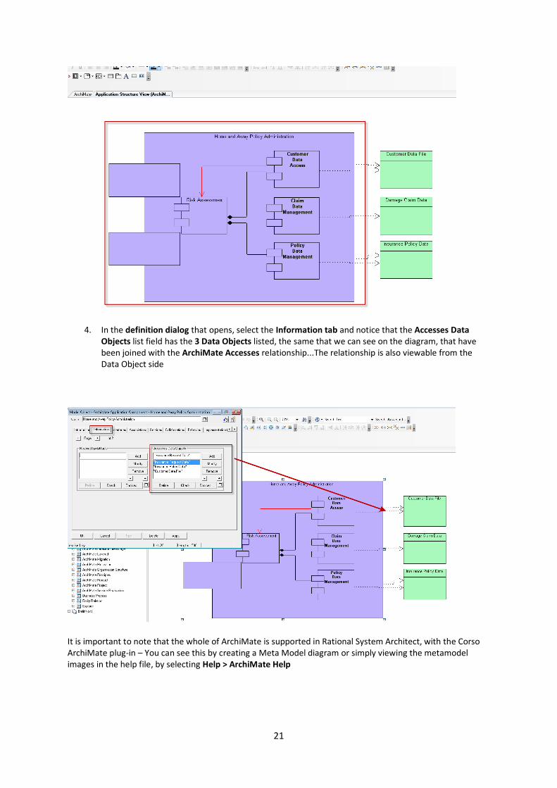
4. In the definition dialog that opens, select the Information tab and notice that the Accesses Data Objects list field has the 3 Data Objects listed, the same that we can see on the diagram, that have been joined with the ArchiMate Accesses relationship...The relationship is also viewable from the Data Object side
It is important to note that the whole of ArchiMate is supported in Rational System Architect, with the Corso ArchiMate plug-in – You can see this by creating a Meta Model diagram or simply viewing the metamodel images in the help file, by selecting Help > ArchiMate Help

22
Graphics Support
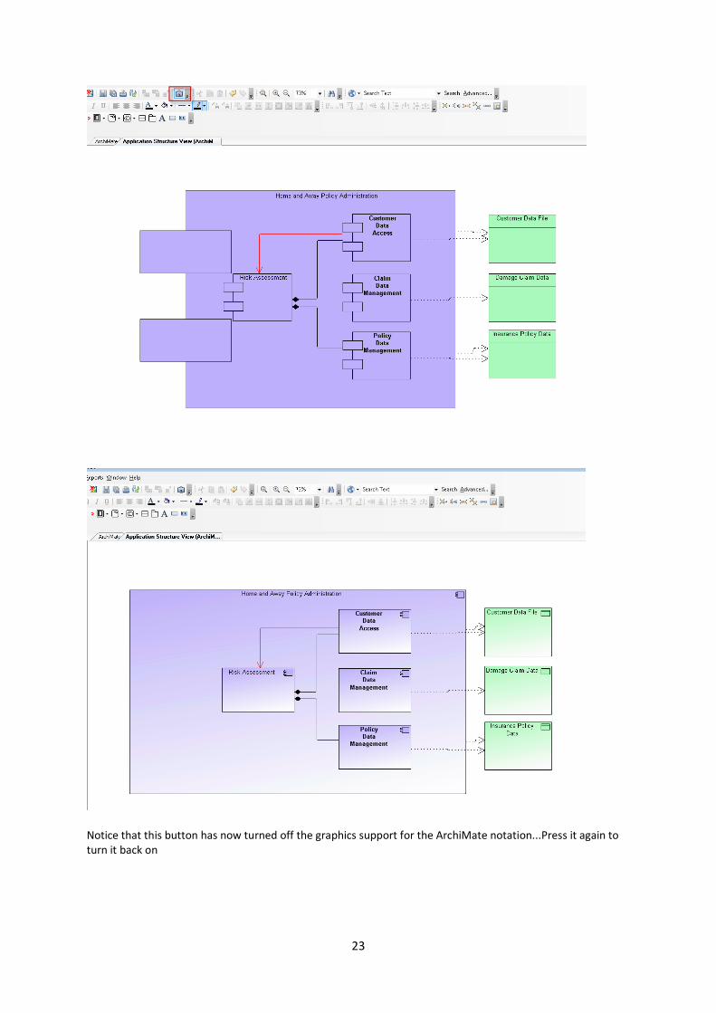
1. With the Application Structure View diagram still open, navigate to the toolbar and press the Symbol Depiction button (looks like the ‘mona lisa’)
23
Notice that this button has now turned off the graphics support for the ArchiMate notation...Press it again to turn it back on
24
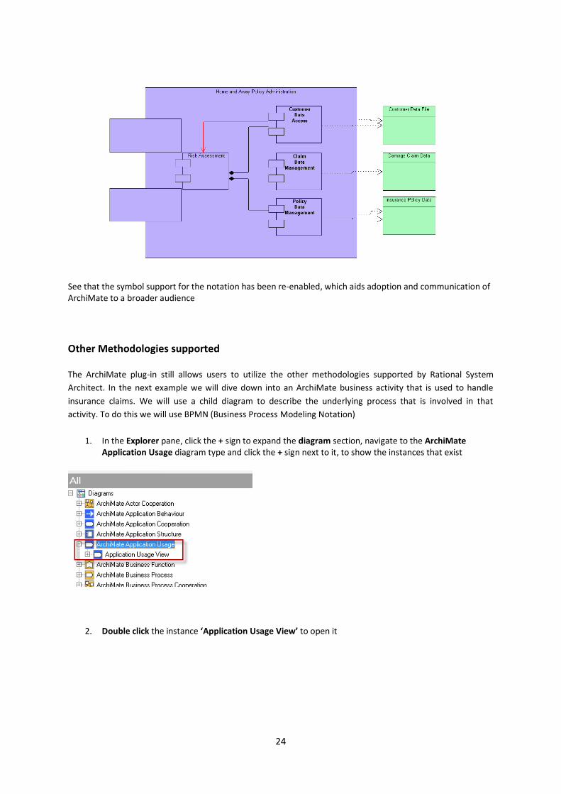
See that the symbol support for the notation has been re-enabled, which aids adoption and communication of ArchiMate to a broader audience
Other Methodologies supported
The ArchiMate plug-in still allows users to utilize the other methodologies supported by Rational System
Architect. In the next example we will dive down into an ArchiMate business activity that is used to handle
insurance claims. We will use a child diagram to describe the underlying process that is involved in that
activity. To do this we will use BPMN (Business Process Modeling Notation)
1. In the Explorer pane, click the + sign to expand the diagram section, navigate to the ArchiMate Application Usage diagram type and click the + sign next to it, to show the instances that exist
2. Double click the instance ‘Application Usage View’ to open it
25
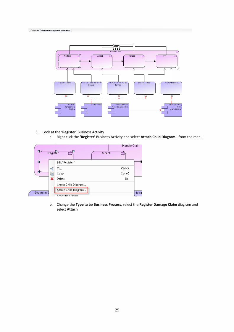
3. Look at the ‘Register’ Business Activity a. Right click the ‘Register’ Business Activity and select Attach Child Diagram...from the menu
b. Change the Type to be Business Process, select the Register Damage Claim diagram and select Attach

26
c. You will be asked to Save the diagram at this time, select Yes d. If asked to Auto refresh the explorer, select Yes
The child diagram will be opened on screen
This gives you the opportunity to use the live drawing, something that BPMN is very good for.
More information on BPMN can be found in the SA help tutorials, found at Help > Getting Started Tutorials, Tutorials > Business Architecture
4. Close the new diagram using the ‘X’ in the right hand corner
(Optional) – Click on the ‘Register’ Business Activity again (you should now see a small downwards facing
arrow in the top left corner, showing there is a child diagram attached) and use the Parent > Child button on
the toolbar to navigate easily between the parent and child diagrams

27
Close all diagrams once finished
Junctions
A junction is used in a number of situations to connect dynamic (triggering or flow) relationships of the same type; e.g., to indicate splits or joins
1. Open Workspace 'Option One', using the Select Workspace option on the left of the toolbar
2. In the Explorer pane, expand the Diagram section and the 'ArchiMate Business Process' Section
3. Open the Business Process Viewpoint diagram

28
4. Select and then delete the trigger line between the 'Investigate' Business Activity and the 'Pay' Business Activity
5. In the Explorer pane, expand the Definitions section and the 'ArchiMate Business Events' Section
a. Select and drag the 'Claim Rejected' object onto the diagram, above the 'Pay' symbol
b. From the toolbar, select the down arrow next to the ArchiMate Junction icon and then choose the 'OR Split' junction type

29
The cursor will now show a + sign, this means the symbol type is selected and you need to select where to put it on the diagram
c. Put it in between the 'Investigate' and the 'Pay' Business Activities
d. Name it OR Split junction (may need to zoom in)
6. Select the 'ArchiMate Triggering' relationship line from the symbol toolbar...Once selected you will see that your arrow is now a cursor...Click the 'Investigate' symbol on the diagram and you will now see a dashed line attached to the symbol, where you move your mouse, the line moves - Move your mouse onto the Junction symbol and click to attach it
30
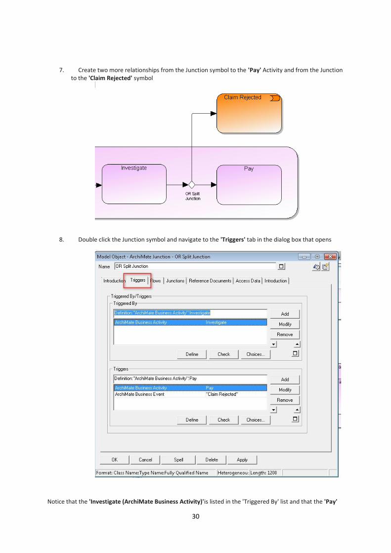
7. Create two more relationships from the Junction symbol to the 'Pay' Activity and from the Junction to the 'Claim Rejected' symbol
8. Double click the Junction symbol and navigate to the 'Triggers' tab in the dialog box that opens
Notice that the 'Investigate (ArchiMate Business Activity)'is listed in the 'Triggered By' list and that the 'Pay'
31
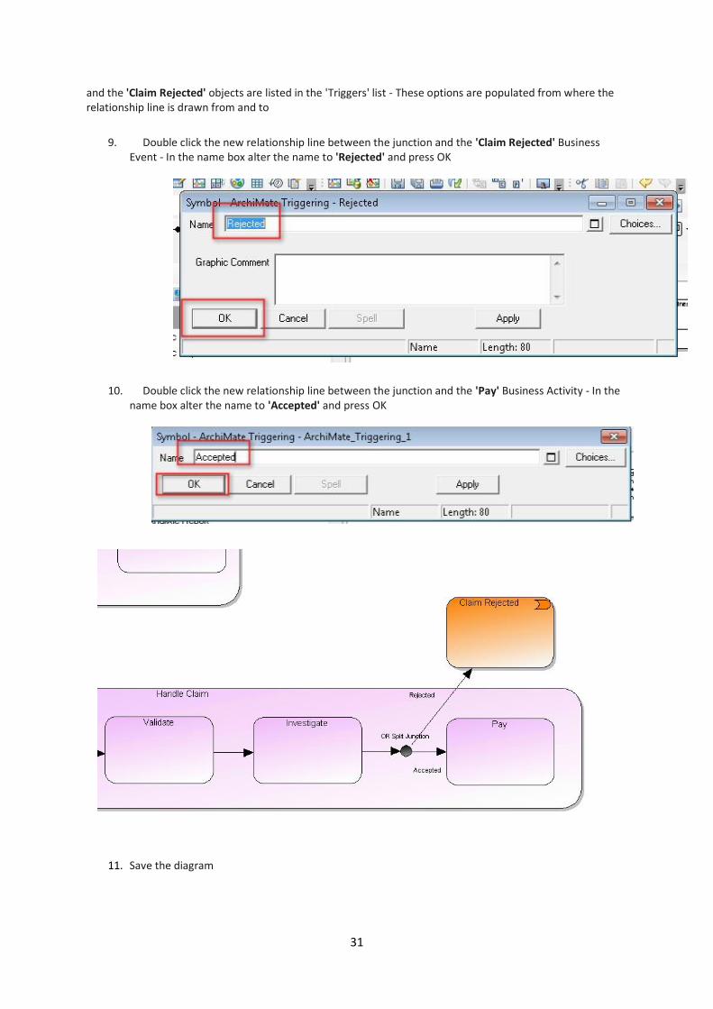
and the 'Claim Rejected' objects are listed in the 'Triggers' list - These options are populated from where the relationship line is drawn from and to
9. Double click the new relationship line between the junction and the 'Claim Rejected' Business Event - In the name box alter the name to 'Rejected' and press OK
10. Double click the new relationship line between the junction and the 'Pay' Business Activity - In the name box alter the name to 'Accepted' and press OK
11. Save the diagram

32
1.5 Representational Consistency
All models are automatically consistent across the model and coherent throughout the views in the repository.
ArchiMate like some other notations specifies model - view behavior where the view is tied to the model; if the view changes then the model changes, and if the model changes then all views which show that part of the model will similarly change. Thus the model and views are kept 'in sync'.
From version 11-4 System Architect has this ability to maintain the lines on diagrams in step with the model as standard, and this implementation of ArchiMate takes advantage of this capability. This behavior is observed when diagrams are opened, at which point System Architect analyses each concept on the diagram and adds or removes lines as per the model of relationships. To force System Architect to update the lines on a diagram hit Tools/Refresh or hit the icon on the toolbar.
Notes on Representational Consistency Performance
The time taken to analyze relationships on a diagram depends on the number of valid symbols for that viewpoint and the number of actual symbols in that view. Diagrams such as the Layered view have a large number of valid relationships so will take longer to load.
The company now wants to allow insurance sellers to perform credit checks. We will walk through creating this relationship by hand and then explore the options using method wizard to construct the new relationship.
1. Navigate back into the Current State Architecture workspace, using the Select Workspace option on
the left of the toolbar

33
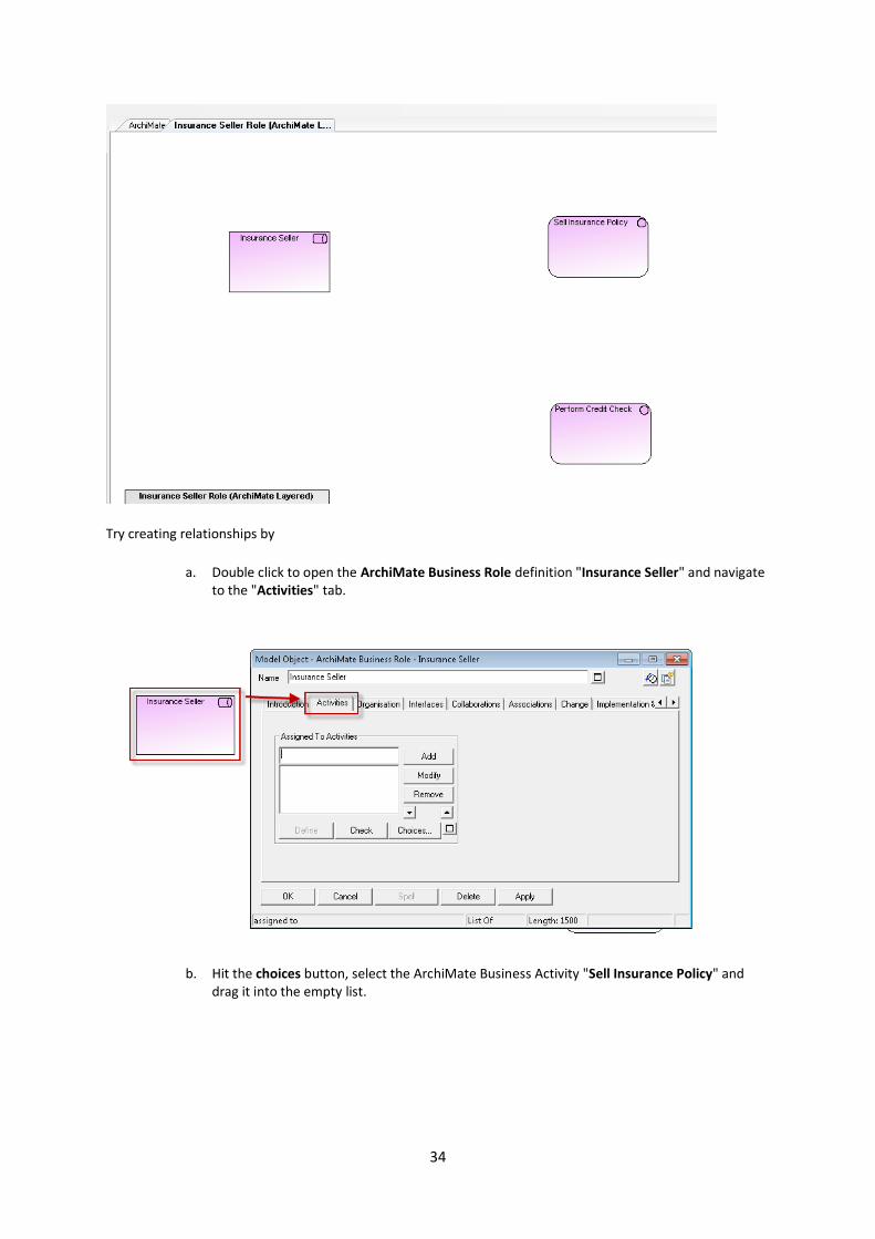
2. Open the ArchiMate Layered Diagram "Insurance Seller Role".
34
Try creating relationships by
a. Double click to open the ArchiMate Business Role definition "Insurance Seller" and navigate to the "Activities" tab.
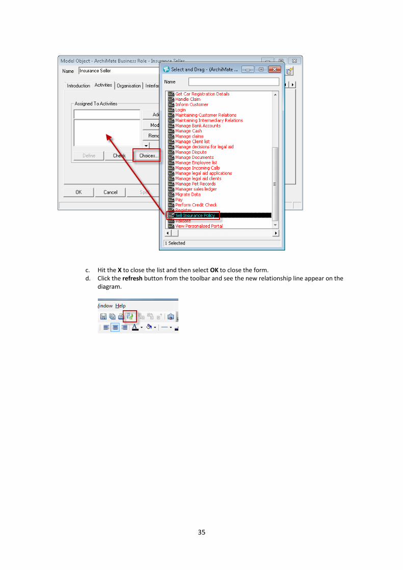
b. Hit the choices button, select the ArchiMate Business Activity "Sell Insurance Policy" and drag it into the empty list.
35
c. Hit the X to close the list and then select OK to close the form. d. Click the refresh button from the toolbar and see the new relationship line appear on the
diagram.
36
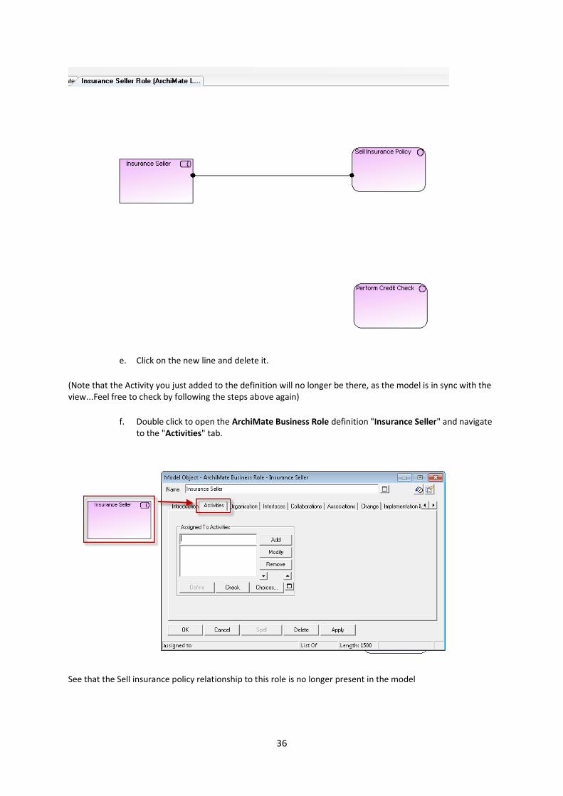
e. Click on the new line and delete it.
(Note that the Activity you just added to the definition will no longer be there, as the model is in sync with the view...Feel free to check by following the steps above again)
f. Double click to open the ArchiMate Business Role definition "Insurance Seller" and navigate to the "Activities" tab.
See that the Sell insurance policy relationship to this role is no longer present in the model

37
3. Draw an Assigns relationship line between ArchiMate Business Role "Insurance Seller" and the ArchiMate Business Activity "Sell Insurance Policy".
a. To do this...Once the Assigns relationship line is selected from the toolbar, to draw the line, simply click on the symbols on the diagram and they will be connected...The definition has been updated to reflect this relationship
The definition has been updated to reflect this relationship
4. Open the matrix browser via the menu option View > Matrix Browser.
38
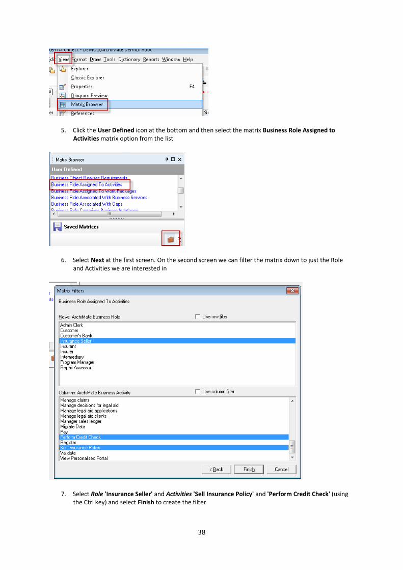
5. Click the User Defined icon at the bottom and then select the matrix Business Role Assigned to Activities matrix option from the list
6. Select Next at the first screen. On the second screen we can filter the matrix down to just the Role and Activities we are interested in
7. Select Role 'Insurance Seller' and Activities 'Sell Insurance Policy' and 'Perform Credit Check' (using the Ctrl key) and select Finish to create the filter
39
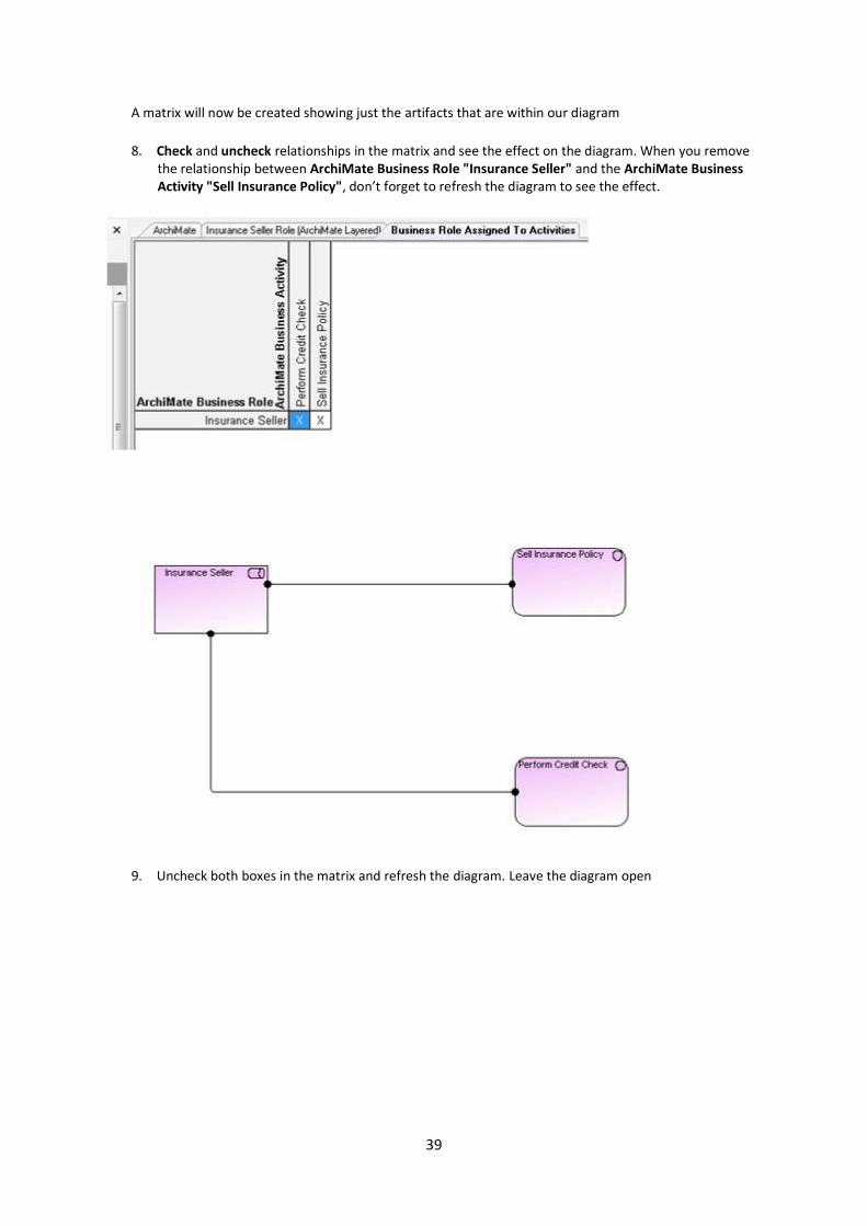
A matrix will now be created showing just the artifacts that are within our diagram
8. Check and uncheck relationships in the matrix and see the effect on the diagram. When you remove the relationship between ArchiMate Business Role "Insurance Seller" and the ArchiMate Business Activity "Sell Insurance Policy", don’t forget to refresh the diagram to see the effect.
9. Uncheck both boxes in the matrix and refresh the diagram. Leave the diagram open
40
1.6 Method Wizard
Example
The following is an attempt to show the complexity of a particular scenario with and without the method wizard to show its value.
The example business concept to be shown is an Insurance Seller performing a Credit Check. It is a relatively simple scenario but the richness of ArchiMate allows a more detailed set of relationships to be modeled which better reflect the complexities of the real world but come at a cost of users trying to understand the underlying ArchiMate model and information that is already defined in the overall set of business relationships across the organization.
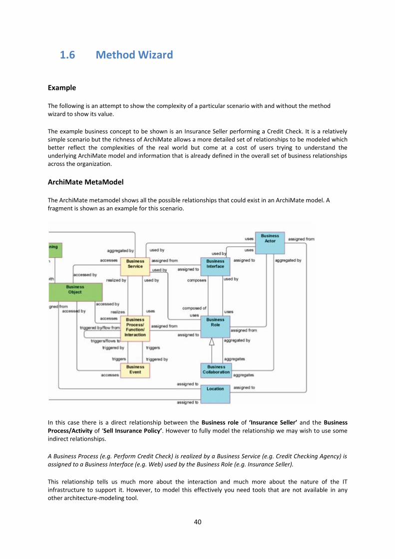
ArchiMate MetaModel
The ArchiMate metamodel shows all the possible relationships that could exist in an ArchiMate model. A fragment is shown as an example for this scenario.
In this case there is a direct relationship between the Business role of ‘Insurance Seller’ and the Business Process/Activity of ‘Sell Insurance Policy’. However to fully model the relationship we may wish to use some indirect relationships.
A Business Process (e.g. Perform Credit Check) is realized by a Business Service (e.g. Credit Checking Agency) is assigned to a Business Interface (e.g. Web) used by the Business Role (e.g. Insurance Seller).
This relationship tells us much more about the interaction and much more about the nature of the IT infrastructure to support it. However, to model this effectively you need tools that are not available in any other architecture-modeling tool.
41
Corso Method Wizard accelerates the creation of enterprise architecture diagrams, saving you precious time. It also encourages collaboration among stakeholders and ensures consistency of frameworks and models.
Simplifies and demystifies Enterprise Architecture
As with other EA tools, IBM Rational System Architect™ will, by default, present complex metamodels and frameworks to the user in their entirety. Method Wizard is designed to address this. Method Wizard was designed by both enterprise architects and end users so it appeals to both groups. Method Wizard helps you navigate and learn models by suggesting the correct relationships and automatically creating them as you draw. Both ArchiMate® and TOGAF as well as customized frameworks are supported, allowing you to quickly and easily create model content within these frameworks.
Benefits users at all levels
Method Wizard is suitable for both novice and experienced users. Novice users will benefit from the automated relationship hinting and line drawing offered by Method Wizard, and will be able to approach tasks with more confidence and motivation. Experienced users will appreciate the speed boost they can acquire when performing repetitive tasks such as configuring relationships.
The Corso Method Wizard© has three functions:
Guide. To guide the user through the metamodel, advising on valid connections between symbols.
Rough Cutting. To allow the user to rough cut models through the use of indirect relationships.
Model Builder. To help the user analyze the model and select appropriate model definitions.
Guide - Direct Relationships
When drawing diagrams there is a wide range of possible line types that can be drawn between symbols. Over time as ArchiMate users become more familiar with the metamodel then choosing the right relationship becomes easier. The Method Wizard© can help, as it knows what are the valid relationships between two symbols. Simply draw a Magic Line between two symbols and The Method Wizard© will guide you.
Rough Cutting and the Model Builder - Indirect relationships
At the start of a modeling project there are many unknowns. We have a rough idea that there are relationships but the detail of these is not yet known. The use of indirect relationships allows us to plot that a relationship exists and allows us to investigate later on. The Method Wizard© will build out the full path of objects and relationships for you allowing you to return to the model later and detail the intermediate objects. The Model builder allows you to select each object in the path step by step and explore existing relationships to help choose the best path.
To use the Method Wizard:
1. Draw a ‘Magic Line’ relationship between the ArchiMate Business Role "Insurance Seller" and the ArchiMate Business Activity "Sell Insurance Policy" and explore the Corso Method Wizard.
a. Select the Magic Line tool from the symbol toolbar b. Click on the "Insurance Seller" symbol and then click on the Sell Insurance Policy" symbol

42
The method wizard will open
2. Select the Direct relationship from the two list boxes - Clicking finish will draw the line and complete the process.
43
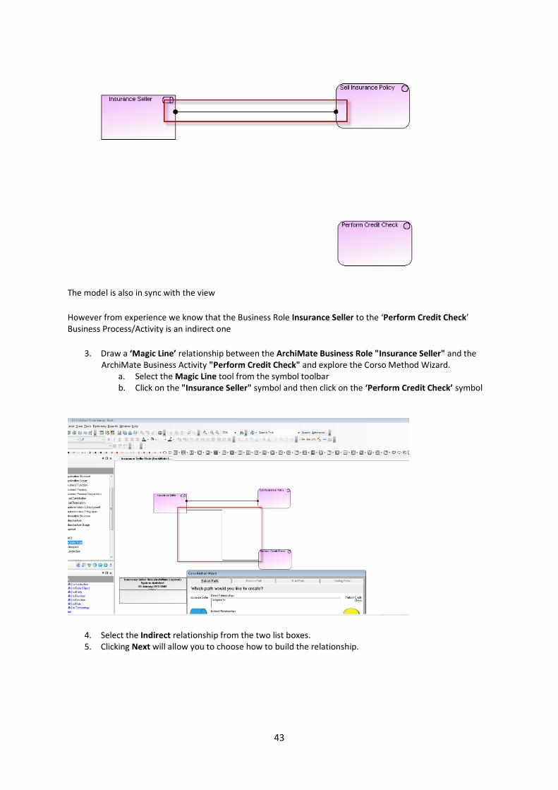
The model is also in sync with the view
However from experience we know that the Business Role Insurance Seller to the ‘Perform Credit Check’ Business Process/Activity is an indirect one
3. Draw a ‘Magic Line’ relationship between the ArchiMate Business Role "Insurance Seller" and the ArchiMate Business Activity "Perform Credit Check" and explore the Corso Method Wizard.
a. Select the Magic Line tool from the symbol toolbar b. Click on the "Insurance Seller" symbol and then click on the ‘Perform Credit Check’ symbol
4. Select the Indirect relationship from the two list boxes. 5. Clicking Next will allow you to choose how to build the relationship.
44
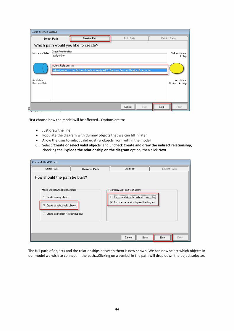
First choose how the model will be affected...Options are to:
Just draw the line
Populate the diagram with dummy objects that we can fill in later
Allow the user to select valid existing objects from within the model 6. Select ‘Create or select valid objects’ and uncheck Create and draw the indirect relationship,
checking the Explode the relationship on the diagram option, then click Next
The full path of objects and the relationships between them is now shown. We can now select which objects in our model we wish to connect in the path...Clicking on a symbol in the path will drop down the object selector.

45
Method Wizard© presents a list of existing objects in the model of that type. Those with existing connections to adjacent objects in the path are shown at the top of the list with an indicator to show which object it is connected to.
7. Select the Business Service object from the list

46
For each unknown element of the relationship then click on the object to see what is already defined elsewhere in the model – if a relationship with another element already exists then it is shown. Hence below the ‘Perform Credit Check’ activity already has a relationship with ‘Credit Checking Agency’ and can be reused or another relationship can be built by clicking on the relevant service. This is a huge advance because without the wizard not only would the user need to know the relationship but would have to go and search for instances of that relationship in the repository.
8. Select this service, ‘Credit Checking Agency’ and then click on the Business Interface
The Service chosen will be shown as part of the chain now in the interface
We can see that the Business Role ‘Insurance Seller’ has access to the ‘Phone’ Business interface, but we need to extend the ‘Web’ Business Interface access to them, to allow them to utilize the Business Service ‘Credit Checking Agency’
9. Select the ‘Web’ Interface 10. Hit Finish and the Method Wizard© will create the path shown on the diagram
47
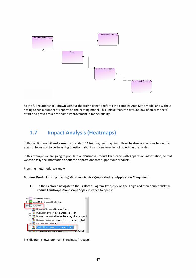
So the full relationship is drawn without the user having to refer to the complex ArchiMate model and without having to run a number of reports on the existing model. This unique feature saves 30-50% of an architects’ effort and proves much the same improvement in model quality
1.7 Impact Analysis (Heatmaps) In this section we will make use of a standard SA feature, heatmapping...Using heatmaps allows us to identify areas of focus and to begin asking questions about a chosen selection of objects in the model
In this example we are going to populate our Business Product Landscape with Application information, so that we can easily see information about the applications that support our products
From the metamodel we know
Business Product >(supported by)>Business Service>(supported by)>Application Component
1. In the Explorer, navigate to the Explorer Diagram Type, click on the + sign and then double click the Product Landscape <Landscape Style> instance to open it
The diagram shows our main 5 Business Products

48
2. Select View > Heat Map Manager to open the pane
(this can take a while when first opening)
Shows a selection of analytics and reports that users can run on this diagram (users can create their own)

49
3. Select the relationship report ‘0Products to Business Services’
Running this report, populates our diagram, box-in-box, via a journey across the metamodel, with the services, also containing the underlying applications that support these Business Products

50
We can now run analytics (reports) that will analyze a property within the underlying applications and match it to a specified answer, coloring either the box or adding a specified symbol to show the result of the analysis
We have analytics set up to show business service dependency on apps in different support states
Fully Supported
Out of Support
Novate (about to be replaced by a new version of the application)
The analytic will place a small colored marker to the left of the application, to identify the property value
We also have analytics set up to show business service dependency on apps with different Disaster recovery plans
Full DR
Partial DR
51
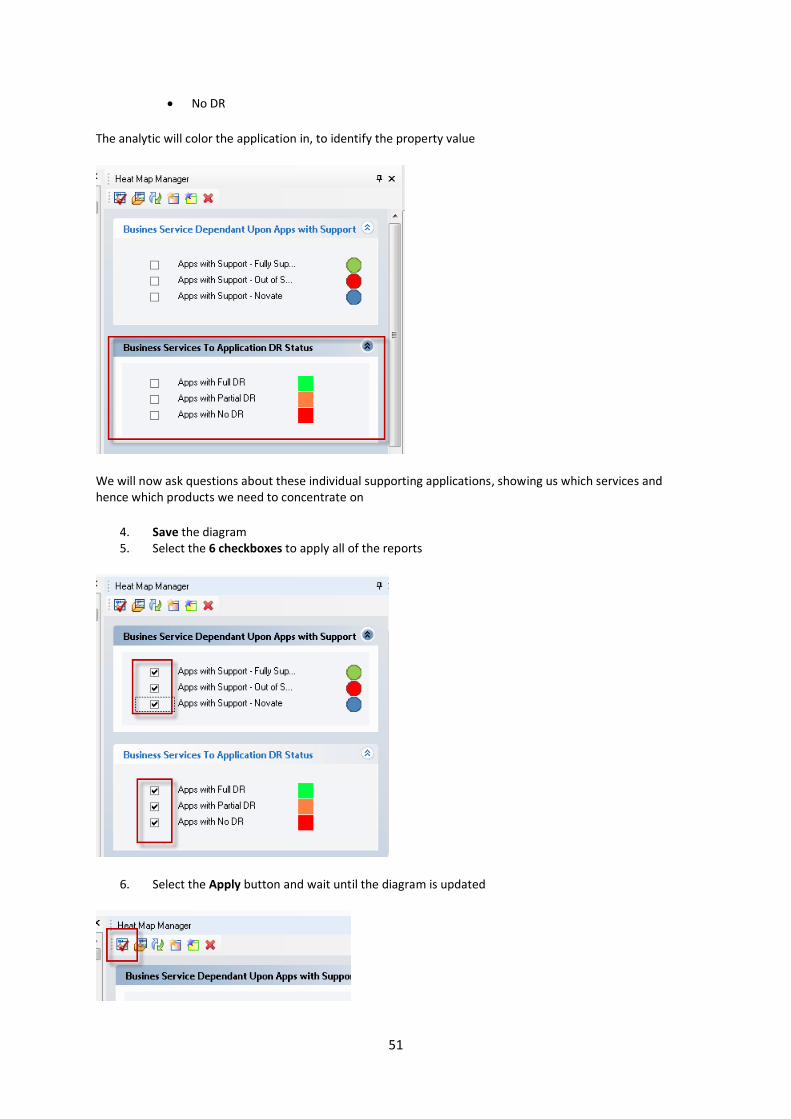
No DR
The analytic will color the application in, to identify the property value
We will now ask questions about these individual supporting applications, showing us which services and hence which products we need to concentrate on
4. Save the diagram 5. Select the 6 checkboxes to apply all of the reports
6. Select the Apply button and wait until the diagram is updated

52
Note: this can take time, depending on the number of relationships that have to be traversed through the metamodel to find the property
Once the diagram is updated we can see that we have many applications with no disaster recovery and that are also out of support – these could be the same underlying applications supporting the services and is where the investigations should start asap, as they could be critical in supporting Business Services and ultimately Products
Using this method is a simple way to help us identify the areas that we need to look at/investigate further...It could also be used to identify other properties of the applications, e.g. Cost
Let’s now take a look at how the Explorer relationship report and analytic reports are constructed to help us see this outcome
7. In the explorer, expand the Definitions section and navigate to the Explorer Relationship Report and expand it

53
8. Double click the 0Products to Business Service <Product> report
9. In the dialog that opens, we can see the report in a textual/code form, select the Edit Content option, so that we can see if using the standard report generator format

54
In the dialog presented we can see that ArchiMate Product is the starting point and RSA uses the DDIDS property to identify which instances are on the diagram, thus selecting the correct related services and placing them within the existing symbols
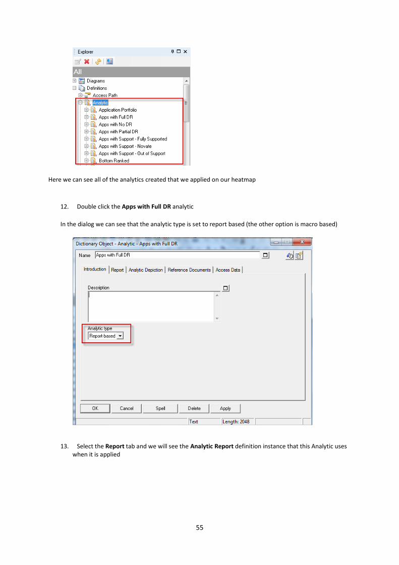
10. Cancel out of the report 11. Back in the explorer, expand the Definitions section and navigate to the Analytics section and
expand it
55
Here we can see all of the analytics created that we applied on our heatmap
12. Double click the Apps with Full DR analytic
In the dialog we can see that the analytic type is set to report based (the other option is macro based)
13. Select the Report tab and we will see the Analytic Report definition instance that this Analytic uses when it is applied
56
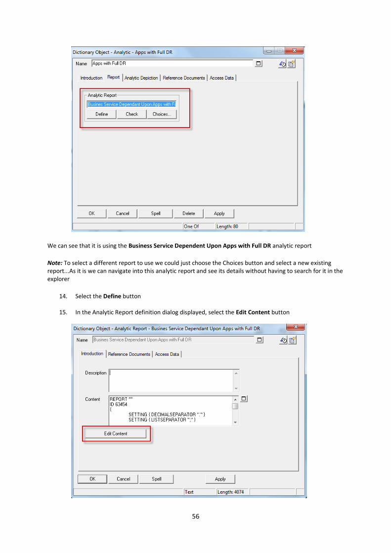
We can see that it is using the Business Service Dependent Upon Apps with Full DR analytic report
Note: To select a different report to use we could just choose the Choices button and select a new existing report...As it is we can navigate into this analytic report and see its details without having to search for it in the explorer
14. Select the Define button
15. In the Analytic Report definition dialog displayed, select the Edit Content button

57
In the report dialog shown, we can see that we are looking at the Business Services and navigating down through the Business Activities it is ‘realized by’ into the Application Components that are ‘assigned to’ it – We are looking at the ‘Disaster Recovery Status’ property value and in this instance if it is Full DR we will color the top level Business Service the specified color (green)
Each analytic that we applied to the diagram uses a report that looks for the ‘Disaster Recovery Status’ property to be set at a different value
16. Close the reporting dialog
1.8 Explorer Diagram
We use the Explorer view/diagram to explore the model we have already built, viewing the relationships between objects e.g. to see which Business Service may have an issue, caused by one of the underlying Applications. In this example we will start with Business Services and break out across activities to components.
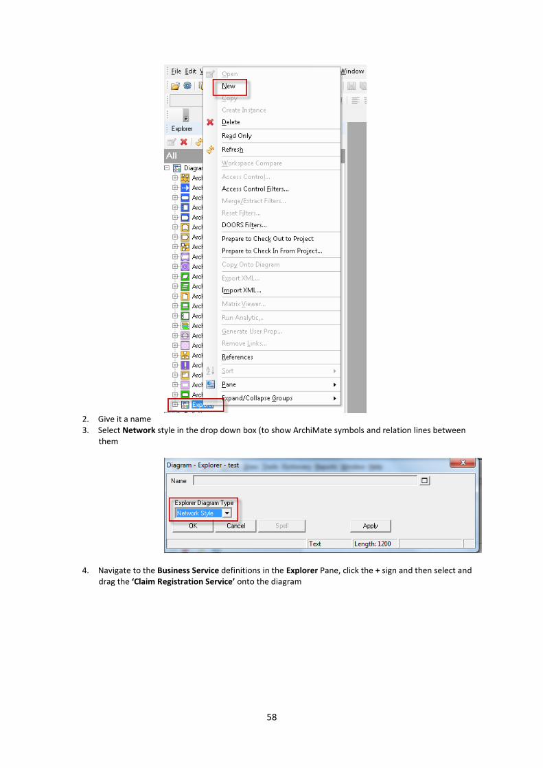
1. Right click on the Explorer type in Diagram section of the Explorer Pane, and select New
58
2. Give it a name 3. Select Network style in the drop down box (to show ArchiMate symbols and relation lines between
them
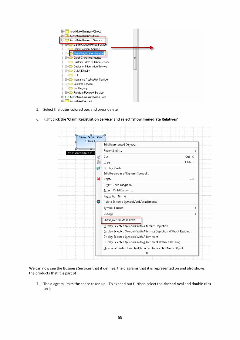
4. Navigate to the Business Service definitions in the Explorer Pane, click the + sign and then select and drag the ‘Claim Registration Service’ onto the diagram
59
5. Select the outer colored box and press delete
6. Right click the ‘Claim Registration Service’ and select ‘Show Immediate Relatives’
We can now see the Business Services that it defines, the diagrams that it is represented on and also shows the products that it is part of
7. The diagram limits the space taken up...To expand out further, select the dashed oval and double click on it
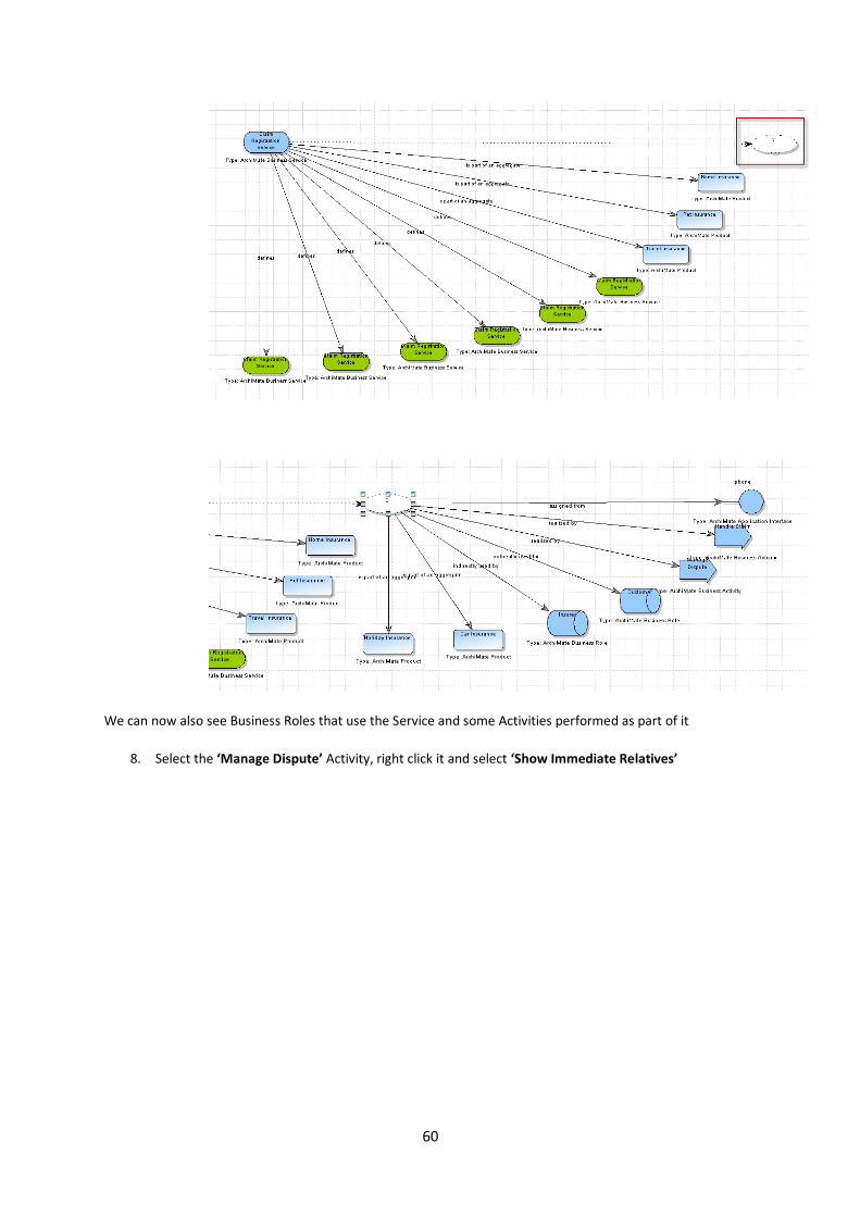
60
We can now also see Business Roles that use the Service and some Activities performed as part of it
8. Select the ‘Manage Dispute’ Activity, right click it and select ‘Show Immediate Relatives’

61
We can now see the other related Activities and also the supporting application components. We can dive into the Application properties if we wanted to...By double clicking the symbol
It is easy to see how quickly and simply we have traversed the metamodel and identified the relationships between objects using the Explorer view...We have easily seen a business service realized by a business activity and supported by application components in a graphical way

62
1.9 Report Generator
Reports are about looking at the data we have built in the model, helping us to explore and answer questions
using the relationships and information we have entered into there
1. From the toolbar, Select Reports > Report Generator...
2. Within the Report Generator, Select File > Open Report File...
3. Find the report file at C:\Program Files (x86)\IBM\Rational\System Architect Suite\System
Architect\Reports\Archimate SA Reports.RPT
Note: You should already be in the correct folder, just need to select the file
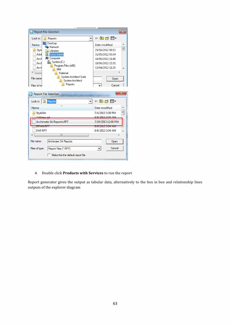
63
4. Double click Products with Services to run the report
Report generator gives the output as tabular data, alternatively to the box in box and relationship lines
outputs of the explorer diagram

64
Note: We can easily see the Business Product, supported by the Business Service that performs the Business
Activity, supported by an Application Component
We can open the object definitions directly from this table and view/explore the properties
5. Close the grid
We will take a look at how the report is constructed
6. With the Products with Services selected, click the Edit button
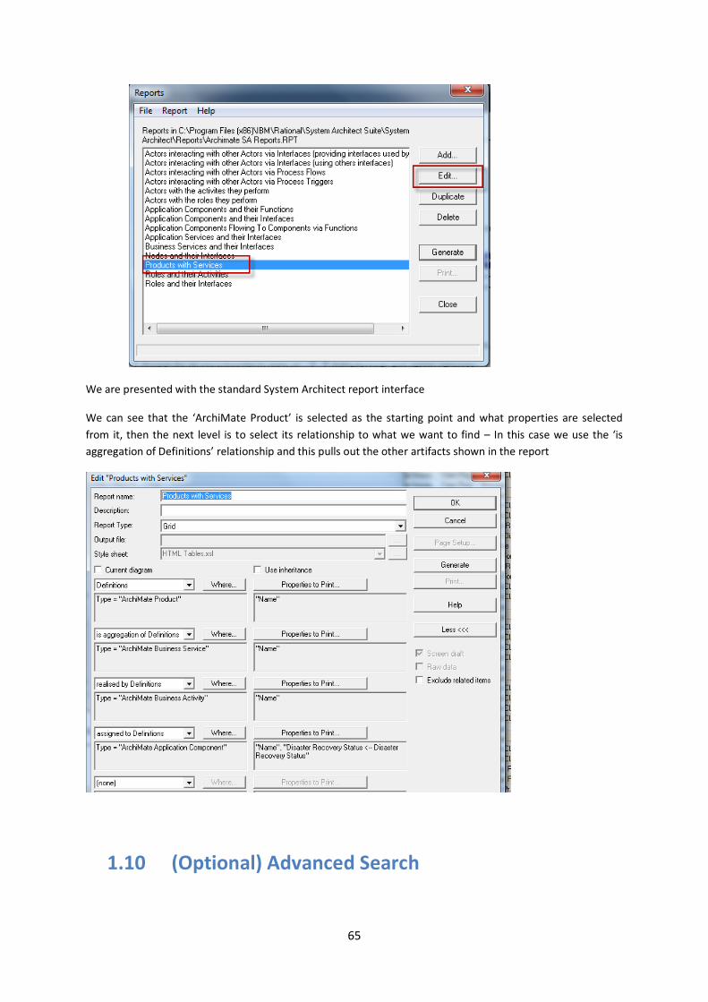
65
We are presented with the standard System Architect report interface
We can see that the ‘ArchiMate Product’ is selected as the starting point and what properties are selected
from it, then the next level is to select its relationship to what we want to find – In this case we use the ‘is
aggregation of Definitions’ relationship and this pulls out the other artifacts shown in the report
1.10 (Optional) Advanced Search

66
1. Select the Advanced button from the toolbar
2. The search utility is very similar to the report interface – We can choose which artifacts to search,
filter by a specific type of artifact, or a property of an artifact to return us the list of information that
we need
3. Select Definitions, leaves All Types checked and in the properties list, select the down arrow and
choose Disaster Recovery Status, with the Value set to Full DR and click OK
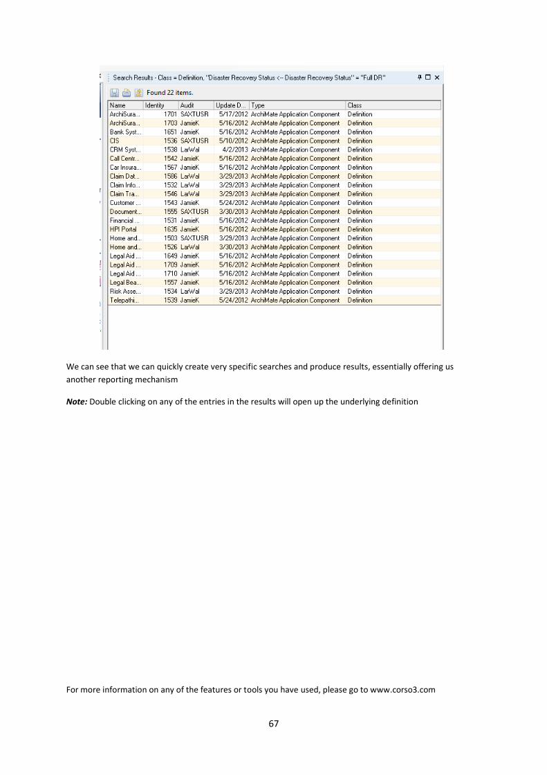
The search function will search for all definitions that have this property set to Full DR and return them to us
4. Expand out the relevant columns and we can see that it has returned a list of ArchiMate Application
Components that have Full DR set for them and a selection of their properties
67
We can see that we can quickly create very specific searches and produce results, essentially offering us
another reporting mechanism
Note: Double clicking on any of the entries in the results will open up the underlying definition
For more information on any of the features or tools you have used, please go to www.corso3.com

68