ibm global services · pdf fileibm global services w28 ... 4.for new orders the...
TRANSCRIPT

IBM GLOBAL SERVICES
W28
Gwen Dente
Nursery School for the Enterprise-Extender-Impaired -- Please Teach Me the Basics!
®
San Francisco, CASeptember 19 - 23, 2005
Page 1

© 2005 IBM Corporation
In recent years the explosive growth of the internet has motivated customers to consolidate their SNA and IP networks to achieve cost and administrative savings, begging the question as to how to support both SNA and IP users and applications over a single network protocol: IP.
Enterprise Extender is one response to this question. But here you are, with your head still swirling about other z/OS and network design topics. And everyone is talking about Enterprise Extender: EE in z/OS, EE in Communications Server for Linux, EE in Cisco. If you feel like an idiot, don't despair. This session enlightens you so that you don't have to day-dream in those planning sessions anymore, and you'll leave this session feeling like an Einstein (maybe a "Baby Einstein")!
The Statement of Direction for a 3745 subset replacement running on LINUX on zSeries, "Communication Controller for LINUX," released in March of 2005, is not covered here.
This session focuses on the Enterprise Extender solution as implemented in z/OS.
Abstract
Page 2
1. Announcement letter 902-040 (2/26/02)2. Effective September 27, 2002, for Machines and December 31, 2002, for MESs IBM will withdraw from marketing all models of
the IBM 3745 Communication Controller and IBM 3746 Nways® Multiprotocol Controller plus selected features and MESs. 3. After February 26, 2002, you will only be able to obtain these products on an as-available basis, directly from IBM or authorized
IBM Business Partners. 4. For new orders the customer-requested arrival date (CRAD) must be no later than October 31, 2002, for machines and January
31, 2003, for MESs. 5. IBM maintenance and other related services, if still available for the product, are not affected by this announcement. IBM will
continue to provide service for the 3745 and 3746 controllers consistent with normal IBM Technical Services service plans and guidelines. Typically IBM will provide service for a minimum of five years from the date of marketing withdrawal. All existing contractual service agreements will be honored. Before committing dates or service periods the geography service planning representative should be contacted.
© 2005 IBM Corporation
AgendaSNA Architecture Overview
Underpinnings of CommunicationSNA Subarea, APPN, APPN/HPR
Enterprise Extender: OverviewCoding Basics for Predefined EE Connections to Replace SNA Network
z/OS to z/OSz/OS to SNASwitch Router
Appendices: Coding Details and Console Logs for EE Transmission Groups
z/OS to z/OSz/OS to SNASwitch Router
Coding for Connection Network with EE Some V1R4 EnhancementsSome V1R5 and V1R6 EnhancementsPlanning for EE
TipsModel Major Nodes
References
Page 3
1. What is driving the move to Enterprise Extender?2. >50% of Business Applications are SNA-Based.3. Globalization and Enterprise Growth are expanding boundaries of IP's reach.4. Globalization and enterprise growth are expanding consumption of MIPs on zSeries.5. Demise of 3745/3746 is pushing enterprises to consolidate around IP networks.6. OSA-Express is the strategic solution for IP connectivity from the zSeries platforms.7. HiperSockets on zSeries is the strategic solution for IP connectivity within the zSeries CEC environment.8. To preserve SNA connectivity across an IP backbone, Enterprise Extender is the silver bullet.9. SNA to IP convergence will promote increased sales of OSA-Es and also zSeries.10. Future SNA packages on LINUX will require Enterprise Extender for connectivity to other SNA applications in the enterprise.11. Further growth of LINUX on zSeries due to incorporation of SNA Communication Server will drive zSeries growth.

© 2005 IBM Corporation
How to Remove Dependency on the 3745/46??
How to Remove Dependency on the 3745??
Migration Path 1: Retain SNA Applications, but convert SNA network to IP.Interconnect SNA Partners with Enterprise Extender ("EE" or "HPR over IP") using APPN/HPR protocols. **STRATEGIC**
Migration Path 2: Retain SNA Applications and the Subarea Protocols, but run NCP inside of Communication Controller for Linux on zSeries ("CCL").An option if SNA partner cannot convert to Strategic EE.
Migration Path 3 - n:Remove dependency on SNA applications by converting them to IP Sockets applications or by sunsetting the applications.Access the SNA Applications with TN3270 or Web technologies that permit access across an IP network.
Page 4
1. Many companies facing this situation are making good use of a redbook to guide them through the process of converting their SNA networking infrastructure to an IP networking infrastructure.1. IBM Communication Controller Guide, SG24-6298, from www.redbooks.ibm.com.
2. One solution available to customers is Enterprise Extender technology.1. EE is available on z/OS VTAM, on Cisco SNASwitch, on PCOMM, on Communications Server for LINUX (INTEL or zSeries),
etc. 3. Another solution is to use the Communications Controller for LINUX (CCL), which resides in a LINUX image on a zSeries and
was introduced in March of 2005. CCL can run an NCP, thus enabling the removal of a 3745.4. Another solution is to migrate to IP technologies, by, for example, exploiting TN3270 for dependent LU sessions or converting
SNA applications to IP applications.5. This presentation focuses on EE.

© 2005 IBM Corporation
SNA Architecture Overview
Page 5

© 2005 IBM Corporation
Underpinnings of CommunicationInformation Information
Connecting two entities in order to exchange information.How to identify and locate the opposite end?
Is there a name or address?How to connect to the opposite end?
Can the message be sent directly or must it be transferred at intermediate stops along the way?
What are the rules to govern an orderly exchange of information?
How to know that the data has been received?How much data should I send at once?
How to end the communication?
Communication ProtocolsNaming and Addressing ConventionsRules for organizing the network topology: nodes and linksRules for connecting communication partners: communication setupRules for routing and exchanging the information
Page 6
1. Architecturally the requirements for communication are layered into "Communication Models." For example, there is a 7-layer OSI model, a 7-layer SNA model, and a four-layer (actually five-layer) TCP/IP model. You have probably heard elsewhere about the physical layer, data link control layer, network layer, transport layer, session layer, presentation layer, application layer of the OSI model. For the purposes of this presentation we have greatly simplified the concept of communication by emphasizing only how to identify and find a partner and how to organize a network topology in order to route information to that partner.
2. Communication involves the exchange of data between two or more partners.3. The partners must have some means by which to be identified. This usually involves naming and addressing conventions.4. We must know how to reach the partner -- know how to locate the partner. Where in the "world" does the communication
partner reside? This function is often called a Directory service.5. We need to know the layout of the "world" or "network" in which the communication partners reside. This is often called a
"network topology" and it comprises nodes and their interconnecting links.6. We need to the best way to send the message to the partner. This is often called a routing service.7. We need to know how to regulate the flow of information -- how much data, how to format it, when to stop communicating, when
to know that the information has arrived, etc. This is often called Session Setup Services or Connection Setup Services together with Flow Control Protocols.
8. In order to understand the pieces of using Enterprise Extender, we need to show you what is available in SNA networking that contributes to the EE architecture. This is what you will see on the subsequent pages.
© 2005 IBM Corporation
NETA
Peripheral Nodes
CICS1 CICS2IMS2
PUBLUB
Networks and ResourcesNetworks may be interconnected (SNI)
GWSSCPs own GWNCPsEach resource within or connected to a subarea has an element number and a name
Resources are predefined at VTAM and at NCPVTAM owns NCP(s) and its resources
Routing between subareas done via predefined PATH tables
Peripheral nodes are attached by links to NCP or to VTAM nodes.
Peripheral nodes (PU Types 2, 2.1, and 1) house Logical Units (LUs) that can engage in communication (sessions) with other LUs.Most LUs depend on an SSCP for session setup services.
Sessions: SSCP-SSCP; SSCP-PU; SSCP-LU for Dependent LUsLU-LU Sessions: Dependent & Independent LUs
VTAMs and NCPs are subarea nodes organized into Networks with NETIDs
Each subarea or Physical Unit Type 5 (VTAM) or Type 4 (NCP) has a unique subarea number within the networkSubarea nodes interconnect by means of links or groups of links known as Transmission Groups (TGs).
VTAMs are known as SSCPs (have SSCPname)
Have SSCP-SSCP sessions with other VTAMs
Use to find resources known as Logical Units (LUs)
NCPs perform Front-End Processing (FEP) to offload some routing and addressing processing from the VTAMs.
Subarea Networking
GWSSCP
NETBNETA
GWNCP
VTAMPU T5SA1
VTAMPU T5SA2
NCPPU T4SA11
NCPPU T4SA12
NCPPU T4SAnn
VTAMPU T5SAyy
PUALUA
Page 7
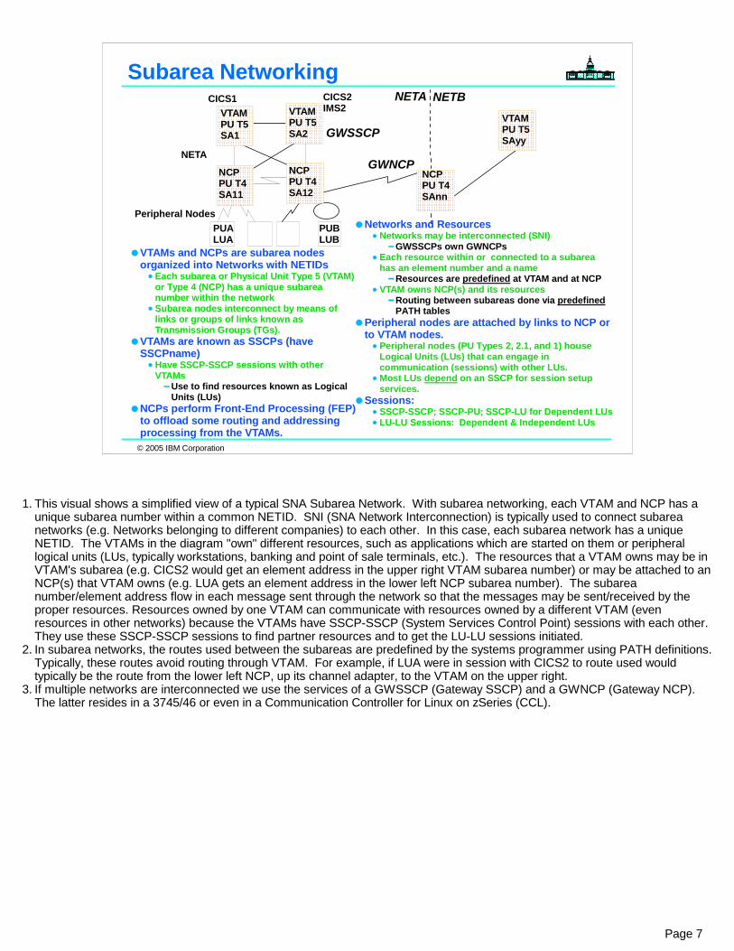
1. This visual shows a simplified view of a typical SNA Subarea Network. With subarea networking, each VTAM and NCP has a unique subarea number within a common NETID. SNI (SNA Network Interconnection) is typically used to connect subarea networks (e.g. Networks belonging to different companies) to each other. In this case, each subarea network has a unique NETID. The VTAMs in the diagram "own" different resources, such as applications which are started on them or peripheral logical units (LUs, typically workstations, banking and point of sale terminals, etc.). The resources that a VTAM owns may be in VTAM's subarea (e.g. CICS2 would get an element address in the upper right VTAM subarea number) or may be attached to an NCP(s) that VTAM owns (e.g. LUA gets an element address in the lower left NCP subarea number). The subarea number/element address flow in each message sent through the network so that the messages may be sent/received by the proper resources. Resources owned by one VTAM can communicate with resources owned by a different VTAM (even resources in other networks) because the VTAMs have SSCP-SSCP (System Services Control Point) sessions with each other. They use these SSCP-SSCP sessions to find partner resources and to get the LU-LU sessions initiated.
2. In subarea networks, the routes used between the subareas are predefined by the systems programmer using PATH definitions. Typically, these routes avoid routing through VTAM. For example, if LUA were in session with CICS2 to route used would typically be the route from the lower left NCP, up its channel adapter, to the VTAM on the upper right.
3. If multiple networks are interconnected we use the services of a GWSSCP (Gateway SSCP) and a GWNCP (Gateway NCP). The latter resides in a 3745/46 or even in a Communication Controller for Linux on zSeries (CCL).

© 2005 IBM Corporation
NN1 NN4
NN3
ENA
ENCCP
CP
CP
TG2
TG1
TG3
TG8
TG6
TG9
NNS Domain
NNS DomainCP
CPTG7
TG1
Network Nodes have CP-CP sessions with adjacent Network Nodes (NNs)Border Nodes or Extended Border Nodes may interconnect SNA Networks (NETIDs)
End Nodes have CP-CP sessions with their Network Node Server (NNS)APPN Nodes are interconnected by means of Transmission Groups (TGs).LUs dynamically located through CP-CP sessions
Most LUs in an APPN network are "independent LUs" residing on intelligent Control Points; they are capable of initiating sessions (sending SNA Session "BINDs") without the assistance of an SSCP.
Routes dynamically calculated by appropriate NNs using APPN COS and Transmission Group ProfilesIf session path breaks, the session breaks
APPN NetworkingNETA NETB
BN
BN
LENB
CP
NN2
CP
BN
Page 8
1. Advanced Peer to Peer Networking (APPN) is an SNA protocol, allowing platforms of different types to network together in a dynamic manner. APPN networks consist of Network Nodes (NN) and End Nodes (EN), although they can also attach to and provide networking functions for subarea networks (VTAMs/NCPs) and Low Entry Networking ("LEN") nodes.
2. Network Nodes (designated with "NN") normally have links (known as transmissions groups, TGs) to and CP-CP (control point to control point) sessions with adjacent NNs. Network Nodes have directory services capabilities such as the ability to dynamically search for and locate resources (logical units, LUs) and the ability to receive information about and inform other nodes about resources (registration). Network Nodes store information about resources in a directory services database. Network Nodes also provide topology and routing services; they dynamically exchange information about link status (operational or not) and the characteristics of the links (such as their speed, level of security, etc.) and are able to dynamically calculate routes for sessions between resources using current information about available routes.
3. End Nodes (designated with "EN") have TGs to and CP-CP sessions with a network node, known as the end node's network node server ("NNS"). The end node may have TGs to other nodes, but only uses one network node server (it may use a backup if the primary is not available), as follows. The end node registers information about its resources (LUs) with its NNS and sends session requests to its NNS. The NNS calculates the best route for the session and informs the end node of the route. Note that the end node can then route the session data directly, not necessarily using a route through its NNS.
4. If networks are interconnected they use the services of a Border Node (designated with "BN") . VTAMs are Extended Border Nodes ("EBNs") and have fewer restrictions on network design than other Border Nodes, called Peripheral Border Nodes.
5. Low-Entry Networking Nodes ("LENs") are intelligent nodes capable of starting sessions themselves. LENs can function in both a subarea and an APPN environment. However, if they are not connected to a Network Node with which they communicate via APPN CP-CP sessions, they require a great deal of pre-definition on themselves and on other nodes in the network in order to find session partners and to set up sessions with those partners.

© 2005 IBM Corporation
What is DLUS/DLUR? APPN & Dependent LUs
APPN EN/NN
VTAMCSSNET.CSS1Subarea 16Network Node
CICS1
OSA - LSA
LU4
CICS1A
APPNNN/ENSupportingPU T2 or T2.1 with Dependent LUs
APPN NN or IP
Network (EE)
DLUS
DLUR
SSCP - PU/LU Sessions
LU-LU Session
VTAMCSSNET.CSS1Subarea 16
CICS1
OSA - LSA
LU4
CICS1A
PU Type 2DependentLU
SSCP - PU/LU Sessions
LU-LU Session
ADJACENT to VTAM or NCP Boundary Function Non-ADJACENT to VTAM or NCP Boundary Function
Subarea Network with Dependent LUs APPN Network with Dependent LUs
Page 9
1. Dependent LUs -- LU 0, LU 1, LU 2, LU 3, and dependent LU 6.2 -- are dependent on the services of an SSCP, a System Services Control Point, in order to establish LU-LU sessions. In a subarea network they are supported by means of SSCP-LU sessions between themselves and their owning SSCP. 1. This is depicted in the diagram on the left.
2. With APPN, Dependent LU Server (DLUS) logic in VTAM V4R2 or higher, and the Dependent LU Requester (DLUR) code of a node providing DLUR function, the adjacency requirement of the traditional SSCP-PU/LU sessions is removed. The diagram shows a configuration that supports SSCP-PU/LU sessions serviced by DLUS/DLUR. Note that the dependent LUs, LU1 and LU2, are connected to an APPN network and are NOT adjacent to VTAM or the VTAM/NCP composite network node. 1. This is depicted in the diagram on the right.
3. DLUS at a VTAM Network Node (or Interchange Node) enables VTAM to establish SSCP-PU and SSCP-LU sessions with PUs and dependent LUs (LU 0, LU 1, LU 2, LU 3, and LU 6.2) on or attached to APPN End Nodes and APPN Network Nodes that have enabled DLUR function. The DLUR nodes with their dependent LUs may reside anywhere in the network.
4. The "DLUR/DLUS Pipe" is used to encapsulate the SSCP flows needed by the dependent resources - the activate physical unit, activate logical unit requests and responses, the MSG10, and the logon requests. The LU-LU session, however, is not encapsulated in the pipe. It flows on the best APPN route and is not required to flow through the DLUS node. It flows in its native protocols (i.e. flows as native LU2 BIND/3270 data stream).
5. The advantages of DLUR are:1. Direct routing (similar to 3745s/3746s) to application host may be achieved
1. Connection network may be used to reduce predefinition requirements2. APPN High Performance Routing (HPR) provides non-disruptive rerouting through node/link failures3. Loss of DLUS is non-disruptive to sessions - a backup DLUS may be automatically connected to by DLURs to handle new
session requests1. Network ownership may be non-disruptively rolled back to the primary DLUS after it is restored
4. Duplicate TIC addressing may be used, if appropriate5. >64K Element Addressing is used 6. Outboard TN3270 Servers available with some DLURs7. New technologies (Enterprise Extender) available on some DLUR platforms
1. DLURs (for dependent LUs) are APPN nodes supporting LU6.2, etc.

© 2005 IBM Corporation
RTP RTPANR
ANR ANR
ANRx
Reroutes sessions in event of a planned or unplanned node or link failure
No impact to end userSupport for application and terminal sessionsSessions rerouted to new route determined by Class of Service
Sessions may be maintained across link "hit" without any switch occurringDiscarded data retransmitted using HPR selective retransmission Congestion control (ARB) adapts to new route
RTP endpoints bring up HPR connections (one or more for each unique COS) which support many sessions using the same APPN Class of Service (COS)
RTP Functions -- All the dynamics of APPN ** plus ** :
High Performance Routing - RTP Overview
Page 10
1. HPR provides the following functions:2. The RTP endpoints can reroute sessions in event of a planned or unplanned node or link failure. They do this by leaving the
sessions up while computing a COS-acceptable route (if one exists) between the RTP endpoints through the remaining links/nodes in the network.
3. This non-disruptive session rerouting has no impact to end users and requires no change to existing applications. The non-disruptive session rerouting supports all types of sessions -- application to application, terminal to application, peripheral LU to peripheral LU, etc..
4. Sessions are rerouted to a new route as determined by the sessions' Class of Service. This means that sessions are not rerouted (they are subsequently taken down) if there is no Class of Service-acceptable route that exists after an outage.
5. An often overlooked advantage of HPR is that it can improve networks that don't even have alternate routing in that sessions may be maintained through a link "hit" without any switch occurring to a new route . The sessions can be maintained while the link goes down and comes back up and the HPR connection can be switched onto the same, restored route, without disruption to the sessions.
6. Any data which is lost or corrupted is selectively retransmitted, meaning that only the bytes in error are retransmitted, not all frames starting after the last acknowledged frame, as is the case with other types of SNA protocols.
7. Congestion control (ARB) adapts to a new route by understanding the link characteristics of the new route and by having a proactive flow control mechanism which computes the optimal sending rate by constantly receiving information concerning the actual receiving rate.
© 2005 IBM Corporation
Application
RTP TCP
ANR IP
DLC
API Sockets
HPR has 2 major componentsRapid Transport Protocol (RTP)
Logical pipe between end pointsMultiple users per RTPError detection and retransmissionCongestion controlPrioritizationNon-disruptive reroute
Automatic Network Routing (ANR)ANR label created at initiationLabel contains all routing informationSNA router strips label and forwards packet
Although TCP/IP networking is completely different, at a high level:RTP is somewhat similar to TCPANR is somewhat similar to IPThe physical connection to the network (DLC) sits underneath
High Performance Routing
Hmmm... If you can use HPR protocols over an IP network, you can use UDP instead of TCP to provide reliability! There's simply no need to execute "reliability" protocols at both the HPR and the
TCP layers!
Page 11
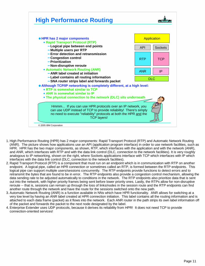
1. High Performance Routing (HPR) has 2 major components: Rapid Transport Protocol (RTP) and Automatic Network Routing (ANR). The picture shows how applications use an API (application program interface) in order to use network facilities, such as HPR. HPR has the two major components, as shown, RTP, which interfaces with the application and with the network (ANR), and ANR, which interfaces with RTP and with the data link control (DLC, connection to the network facilities). It is very roughly analogous to IP networking, shown on the right, where Sockets applications interface with TCP which interfaces with IP which interfaces with the data link control (DLC, connection to the network facilities).
2. Rapid Transport Protocol (RTP) is a component that must run on an endpoint which is in communication with RTP on another endpoint. A logical pipe, called an HPR connection or sometimes called an RTP, is formed between the RTP endpoints. This logical pipe can support multiple users/sessions concurrently. The RTP endpoints provide functions to detect errors and to retransmit the bytes that are found to be in error. The RTP endpoints also provide a congestion control mechanism, allowing the data sending rate to be adjusted automatically to conditions in the network. The RTP endpoints also prioritize data that is sent out into the network, with higher priority frames being sent before lower priority ones. Lastly, the RTPs allow for non-disruptive reroute -- that is, sessions can remain up through the loss of links/nodes in the session route and the RTP endpoints can find another route through the network and have the route for the sessions switched onto the new path.
3. Automatic Network Routing (ANR) is a function available in NNs which have HPR functionality. ANR allows for switching at a very low level by having an ANR label created at HPR connection initiation. This label contains all the routing information and is attached to each data frame (packet) as it flows into the network. Each ANR router in the path strips its own label information offof the packet and forwards the packet to the next node designated by the label.
4. Enterprise Extender uses UDP protocols, because it derives its reliability from HPR! It does not need TCP to provide connection-oriented services!

© 2005 IBM Corporation
VTAM VTAM
VTAM NCP
NCP NCP
LEN
VTAMV4
APPNAPPN/HPR
InterchangeNodeSubarea
SNI
Peripheral Nodes, PUsIndependent & Dependent LUs
IP Backbone
Many customer networks are combination Subarea and APPN/HPR networksSessions may occur between resources in Subarea and APPN/HPR networksSome or all of the APPN/HPR network may use IP connectivity (EE)Peripheral resources may be attached via subarea or APPN/HPR DLUR nodes
Single SNA Network, e.g. NETA
Another SNA Network, e.g. NETB
Peripheral Nodes, PUs, Independent & Dependent LUs
SNA Networking Today
Page 12
1. This visual shows a typical customer's SNA network. Notice that is a combination subarea/APPN network. Some of the resources are attached using subarea networking and some use APPN networking. A VTAM defined as an Interchange Node, such as the one in the center is able to "interchange" between subarea and APPN protocols. This allows resources in the APPN network to communicate with resources in the subarea network. Notice the customer's network (NETA) consists of both subarea and APPN nodes. This customer's network is also attached to another network (NETB) using SNI. Any of the resources in NETA may communicate with resources in NETB in this visual.

© 2005 IBM Corporation
Overview of Enterprise Extender
Page 13

© 2005 IBM Corporation
How can I retain my SNA sessions while eliminating the SNA networking infrastructure and utilizing only the IP network? How can I replace my 3745s, which will no longer be supported in the future, and yet still interconnect separate SNA networks? How can I exploit my OSA Gigabit adapters and my HiperSockets on the zSeries for SNA sessions?
TCP/IP Network
VTAMUSIBMWZ.S192CDRM
VTAMUSIBMWZ.S193CDRM
IP Device and Link
OSA - QDIO
TCP/IP #1
FTP Client
TCP/IP Router
FTP Server1
TCP/IP #2
FTP Server2
FTP Client
10.1.1.1 10.2.2.2
TCP/IP Router TCP/IP Router
10.3.3.3
OSA - QDIO
How to Remove Dependency on the 3745/46??
VTAMUSSIBMWZ.S192CDRMSubarea 16APPN NN
VTAMUSIBMWZ.S193CDRMSubarea 13APPN NN
OSA - LSA OSA - LSA
3745/6NCP
LU2
LU3
LU-LU Session LU-LU
Session
CICS1 CICS2LU-LU Session
ILU
CICS1A
LEN
2 LU-LU Sessions
SA TG(Link)
NETID=USIBMWZ
NETID=CSSNET
SNA Network(s)
Page 14

© 2005 IBM Corporation
How to Remove Dependency on the 3745/46??
How to Remove Dependency on the 3745??
Migration Path 1: Retain SNA Applications, but convert SNA network to IP.Interconnect SNA Partners with Enterprise Extender ("EE" or "HPR over IP") using APPN/HPR protocols. **STRATEGIC**
Migration Path 2: Retain SNA Applications and the Subarea Protocols, but run NCP inside of Communication Controller for Linux on zSeries ("CCL").An option if SNA partner cannot convert to Strategic EE.
Migration Path 3 - n:Remove dependency on SNA applications by converting them to IP Sockets applications or by sunsetting the applications.Access the SNA Applications with TN3270 or Web technologies that permit access across an IP network.
Page 15
1. Many companies facing this situation are making good use of a redbook to guide them through the process of converting their SNA networking infrastructure to an IP networking infrastructure.1. IBM Communication Controller Guide, SG24-6298, from www.redbooks.ibm.com.
2. One solution available to customers is Enterprise Extender technology.1. EE is available on z/OS VTAM, on Cisco SNASwitch, on PCOMM, on Communications Server for LINUX (INTEL or zSeries),
etc. 3. Another solution is to use the Communications Controller for LINUX (CCL), which resides in a LINUX image on a zSeries and
was introduced in March of 2005. CCL can run an NCP, thus enabling the removal of a 3745.4. Another solution is to migrate to IP technologies, by, for example, exploiting TN3270 for dependent LU sessions or converting
SNA applications to IP applications.5. This presentation focuses on EE.
© 2005 IBM Corporation
Enterprise Extender (EE): Merging the SNA and IP Networks
Implement APPN/HPR at selected SNA nodes in the network(s)Define Enterprise Extender TGs/Links over the IP network
VTAM views links as APPN TGsAPPN Topology
IP network views EE TG as one or more hops along an IP routing path
IP Topology
If using SNA Network Interconnect (SNI), implement APPN Border Node (BN) and eliminate NCPsWhere appropriate, implement Enterprise Extender with SNASwitch implementation at Cisco routers or with Communications Server for Linux, Windows, AIX, etc.For Dependent LUs, implement DLUR/DLUS at appropriate nodes
DLUR at SNASwitchDLUR at Communications Server for LINUXDLUR at PCOMMetc.
VTAMUSIBMWZ.S192CDRMSubarea 16
VTAMUSIBMWZ.S193CDRMSubarea 13
IP Device and Link
TCP/IP #1
TCP/IP Router
SNA APPL
TCP/IP #2
SNA APPL
10.1.1.1 10.2.2.2
TCP/IP Router TCP/IP Router
10.3.3.3
IP NETWORK
TCP/IP RouterTCP/IP Router
NETID=CSSNET
(BN)(BN)
DLUS DLUS
DLUR
QDIO QDIO QDIO QDIO
(BN)
(EE)
(EE) (EE)
(EE)
NETID=USIBMWZ
Page 16
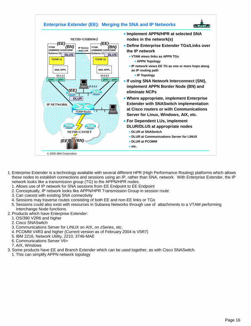
1. Enterprise Extender is a technology available with several different HPR (High Performance Routing) platforms which allows these nodes to establish connections and sessions using an IP, rather than SNA, network. With Enterprise Extender, the IP network looks like a transmission group (TG) to the APPN/HPR nodes. 1. Allows use of IP network for SNA sessions from EE Endpoint to EE Endpoint2. Conceptually, IP network looks like APPN/HPR Transmission Group in session route3. Can coexist with existing SNA connectivity4. Sessions may traverse routes consisting of both EE and non-EE links or TGs 5. Sessions could also exist with resources in Subarea Networks through use of attachments to a VTAM performing
Interchange Node functions. 2. Products which have Enterprise Extender:
1. OS/390 V2R6 and higher 2. Cisco SNASwitch3. Communications Server for LINUX on AIX, on zSeries, etc.4. PCOMM V4R3 and higher (Current version as of February 2004 is V5R7)5. IBM 2216, Network Utility, 2210, 3746-MAE6. Communications Server V6+ 7. AIX, Windows
3. Some products have EE and Branch Extender which can be used together, as with Cisco SNASwitch.1. This can simplify APPN network topology

© 2005 IBM Corporation
Enterprise Extender Overview
1. Enterprise Extender is a technology that allows SNA Data to flow between SNA nodes across a UDP/IP network.A. Native IP routing within network maximizes router efficiency.
Pure end-to-end IP network into zSeries possibleB. SNA applications benefit from advances in IP routing.C.Solution can eliminate need for 3745s with NCP in many cases.
2. The EE connection looks like an SNA Link or Transmission Group (TG).A. The EE TG can be predefined or can be dynamically defined to use "APPN
Connection Network."3. The EE TG extends from one EE Endpoint on one side of the IP network to another
EE Endpoint on the remote side of the IP network.4. The EE Endpoint consists of an SNA component tied to an IP component.
EE Link or "Transmission Group" (TG)
IP Network
EE Endpoint EE Endpoint
SNA SNAIP IP
44
3 3
SNA Data between SNA Applications
1
2
Page 17

© 2005 IBM Corporation
Enterprise Extender Overview
1. Enterprise Extender uses "unreliable, connectionless" UDP in the IP network, but it derives its reliability from APPN/HPR architecture, which provides:A.Error detection and retransmissionB.Non-disruptive rerouteC.Congestion controlD.Prioritization
2. Beneath the single EE connection you might find multiple IP links interconnected by means of multiple IP routers.A.Availability of the IP network is provided by redundant paths and preferably dynamic routing protocols.B.The IP network provides the packet forwarding, using IP Type of Service which has been mapped to the SNA
priorities.3. The EE Endpoint is identified by means of an IP address ('IP@') or a Hostname that
is resolved to an IP address. 4. Platform-specific coding ties SNA to IP within the EE Endpoint node.
IP Network
EE Endpoint EE Endpoint
EE Link or "Transmission Group" (TG)
SNA SNAIP IP3 3
SNA Data between SNA Applications
1
2
IP@ IP@
44
SNA Definitions > < IP Definitions IP Definitions> < SNA Definitions
Reliability >>>>
<<<< Reliability
Page 18
© 2005 IBM Corporation
Enterprise Extender Overview
EE Endpoint is the Link destination and is defined as IP address or host name
Connection network may be usedNative IP routing within network maximizes router efficiency
Pure end-to-end IP network into zSeries possible
SNA applications benefit from advances in IP routing
Enables single network transportHPR provides
Error detection and retransmissionNon disruptive rerouteCongestion controlPrioritization
IP provides packet forwardingSNA priority mapped to TOS Use of standard UDP ports
RTP Connection
SNA Application
RTP
DLC
API
RTP
IP
DLC
API
Fast UDP
Fast UDP
IUTSAMEH
z/OS
SNA Application
z/OS
IUTSAMEH
USIBMWZ USIBMWZ
IP Network
IP@ IP@
EE Link or "Transmission Group" (TG)
IPSNA IP IPSNA IP
Page 19
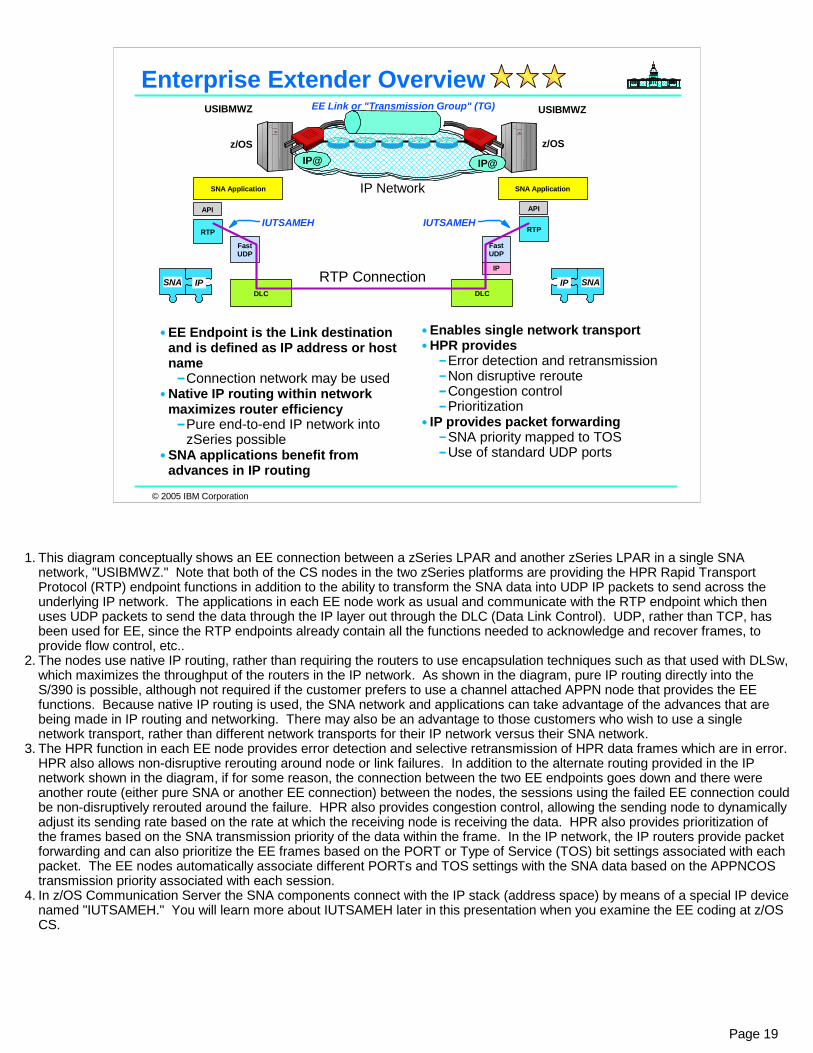
1. This diagram conceptually shows an EE connection between a zSeries LPAR and another zSeries LPAR in a single SNA network, "USIBMWZ." Note that both of the CS nodes in the two zSeries platforms are providing the HPR Rapid Transport Protocol (RTP) endpoint functions in addition to the ability to transform the SNA data into UDP IP packets to send across the underlying IP network. The applications in each EE node work as usual and communicate with the RTP endpoint which then uses UDP packets to send the data through the IP layer out through the DLC (Data Link Control). UDP, rather than TCP, has been used for EE, since the RTP endpoints already contain all the functions needed to acknowledge and recover frames, to provide flow control, etc..
2. The nodes use native IP routing, rather than requiring the routers to use encapsulation techniques such as that used with DLSw, which maximizes the throughput of the routers in the IP network. As shown in the diagram, pure IP routing directly into the S/390 is possible, although not required if the customer prefers to use a channel attached APPN node that provides the EE functions. Because native IP routing is used, the SNA network and applications can take advantage of the advances that are being made in IP routing and networking. There may also be an advantage to those customers who wish to use a single network transport, rather than different network transports for their IP network versus their SNA network.
3. The HPR function in each EE node provides error detection and selective retransmission of HPR data frames which are in error. HPR also allows non-disruptive rerouting around node or link failures. In addition to the alternate routing provided in the IP network shown in the diagram, if for some reason, the connection between the two EE endpoints goes down and there were another route (either pure SNA or another EE connection) between the nodes, the sessions using the failed EE connection could be non-disruptively rerouted around the failure. HPR also provides congestion control, allowing the sending node to dynamically adjust its sending rate based on the rate at which the receiving node is receiving the data. HPR also provides prioritization of the frames based on the SNA transmission priority of the data within the frame. In the IP network, the IP routers provide packet forwarding and can also prioritize the EE frames based on the PORT or Type of Service (TOS) bit settings associated with each packet. The EE nodes automatically associate different PORTs and TOS settings with the SNA data based on the APPNCOS transmission priority associated with each session.
4. In z/OS Communication Server the SNA components connect with the IP stack (address space) by means of a special IP device named "IUTSAMEH." You will learn more about IUTSAMEH later in this presentation when you examine the EE coding at z/OS CS.

© 2005 IBM Corporation
Enterprise Extender Overview - BN
z/OS CS Border Nodes (capable of "Multiple Network Connectivity" may interconnect separate SNA Networks using EE Technology
Only z/OS Border Nodes are EE-capable (Not VSE or VM Border Nodes)Link destination defined as IP address or host name
Global Connection network may be used (aka Global Virtual Routing Node)
RTP Connection
SNA Application
RTP
IP
DLC
API
RTP
IP
DLC
API
Fast UDP
Fast UDP
IUTSAMEH
z/OS
SNA Application
z/OS
IUTSAMEH
(BN) (BN)
EE Link or "Transmission Group" (TG)
IP Network
CSSNETUSIBMWZ
Page 20
1. This diagram conceptually shows an EE connection between a zSeries LPAR and another zSeries LPAR, but this time they reside in separate SNA networks: "USIBMWZ" and "CSSNET."
2. The advantages of Enterprise Extender are the same as what we have previously seen, but now we can actually provide cross-network communication without having to implement an SNI connection. 1. SNI requires a GWSSCP and a GWNCP. GWNCPs reside in 3745s, which have been discontinued from marketing.
"Communication Controller for LINUX on zSeries" (CCL) permits a subset of NCP functions to run within a LINUX on zSeries image. CCL became available in March of 2005. CCL is not the subject of this presentation. It is, however, a viable technology for those SNA sites that are prevented from migrating to Enterprise Extender. (Reasons might be: lack of EE technology at partner site; unwillingness to migrate to EE or lack of readiness of partner site.)
3. Note that other platforms provide Border Node capability, like VSE/VTAM or VM/VTAM. However, neither of these platforms can represent an EE endpoint. Their Border Node (or "Multiple Network Connectivity") capability is restricted to native APPN/HPR networking infrastructures as they remain at a VTAM V4R2 capability level..

© 2005 IBM Corporation
Enterprise Extender Overview - DLUR
Dependent LU Requestor can reside at an EE nodeCisco SNASwitchCommunications Server for Linux on zSeriesCommunications Server for Linux on IntelCommunications Server for Linux on AIXCommunications Server for Linux on Windows
RTP Connection
SNA Application
RTP
IP
DLC
API
IBM
SNA Application/DLUR
RTP
IP
DLC
API
Fast UDP
Fast UDP
IUTSAMEH
z/OS
Partner EE Endpoint: (non-z/OS)
DLUS DLUR
EE Link or "Transmission Group" (TG)
IP Network
Page 21
1. This diagram conceptually shows an EE connection between a zSeries LPAR and a DLUR node. Native SNA nodes are attached to the DLUR router using the normal LAN or link connections that they've used previously. Note that both CS in the zSeries and the HPR DLUR functions in the router are providing the HPR Rapid Transport Protocol (RTP) endpoint functions in addition to the ability to transform the SNA data into UDP IP packets to send across the underlying IP network. The applications in each EE node work as usual and communicate with the RTP endpoint which then uses UDP packets to send the data through the IP layer out through the DLC (Data Link Control). UDP, rather than TCP, has been used for EE, since the RTP endpoints already contain all the functions needed to acknowledge and recover frames, to provide flow control, etc..
2. Note how z/OS uses IUTSAMEH device to interconnect SNA with IP on the EE endpoint.3. Other platforms do not use the IUTSAMEH construct to create the communication path between SNA and IP components within
a node. Their coding techniques employ other means to interconnect the SNA protocol with the IP protocol o the EE endpoint.

© 2005 IBM Corporation
Enterprise Extender Overview - DLUR + TN3270
The DLUR-serviced PUs and LUs can even reside in a TN3270 Server at the DLUR node
Cisco SNASwitchCommunications Server for Linux on zSeriesCommunications Server for Linux on IntelCommunications Server for Linux on AIXCommunications Server for Linux on Windows
IBM
z/OS
DLUS DLUR
Partner EE Endpoint: (non-z/OS)
IBMz/OS
DLUS DLUR
Partner EE Endpoint: (non-z/OS)
TN3270
IP Network
IP Network IP Network
EE Link or "Transmission Group" (TG)
EE Link or "Transmission Group" (TG)
SNA Network
Page 22
1. This diagram conceptually shows an EE connection between a zSeries LPAR and a DLUR node. 2. In the uppermost visual, native SNA nodes are attached to the DLUR router using the normal LAN or link connections that
they've used previously. Note that both CS in the zSeries and the HPR DLUR functions in the router are providing the HPR Rapid Transport Protocol (RTP) endpoint functions in addition to the ability to transform the SNA data into UDP IP packets to send across the underlying IP network. The applications in each EE node work as usual and communicate with the RTP endpoint which then uses UDP packets to send the data through the IP layer out through the DLC (Data Link Control). UDP, rather than TCP, has been used for EE, since the RTP endpoints already contain all the functions needed to acknowledge and recover frames, to provide flow control, etc..
3. The lower visual shows how TN3270 clients can telnet into a TN3270 server on a DLUR node and then connect to the DLUS node at z/OS over an IP network using Enterprise Extender with SNA protocols!

© 2005 IBM Corporation
More Advantages of Enterprise Extender
No changes to SNA applicationsFully enables parallel sysplexCan reduce APPN network complexity while exploiting IP alternate routing/redundancy technologiesSNA traffic can exploit OSA Gigabit EthernetEE can use any zSeries IP network connection -- channel attached router, OSA, HiperSockets, etc.Most EE platforms can define IP network as a "connection network", allowing fewer link definitions, but direct routingEE works with IPSECEE works with Network Address Translation (NAT)
If using NAT, address administration required for EE EE Connection Network doesn't work with NAT until z/OS V1R5 (i.e., prior to V1R5, NAT with predefined EE TGs works fine.)
Multiple EE Endpoint IP Addresses are possible starting with z/OS V1R5
Page 23
1. The advantages of Enterprise Extender include features you have heard about on previous pages and new ones on this page. 1. SNA transport over native IP network - EE allows SNA resources to access each other using an underlying IP network,
eliminating the need to provide two different networks, one for SNA and one for IP, as many customers do today.2. No changes to SNA applications - the use or implementation of EE nodes in the network is transparent to the SNA
applications. They can participate in sessions (all kinds -- APPC, LU2, LU1, LU0, etc.) without change because the underlying IP network just looks like an APPN/HPR TG to the SNA network.
3. Fully enables parallel sysplex - the SNA Parallel Sysplex functions are dependent upon using APPN and HPR within the Parallel Sysplex. As compared with HPR just within the Parallel Sysplex, implementing EE in the network can provide higher availability since HPR can be exploited to route around additional node/link failures.
4. End-to-End failure protection - because EE uses the underlying HPR technology, there is much more end-to end failure protection as compared with older SNA technologies, such as subarea networking, DLSw, etc..
5. End-to-End data prioritization -- EE by default implements setting of different PORTs and different Type of Service (TOS) bits based on the APPN Class of Service being used (network, high, medium, or low priority).
6. Can reduce complexity - because EE exploits use of underlying IP network alternate routing technologies, there is reduced need to implement a lot of network nodes and links between them in the SNA portion of the network. EE can also be combined with Branch Extender technology, allowing routers to appear as ENs, rather than NNs, thereby simplifying the APPN network design.
7. SNA traffic can exploit OSA Gigabit Ethernet -- the OSA Gigabit Ethernet, which has produced impressive throughput benchmark results, does not support SNA (only TCP/IP) connections. With use of EE, the SNA traffic can exploit the very high speed connectivity provided by the OSA Gigabit Ethernet adapter as well as any zSeries IP network connection -- channel attached router, OSA, etc.. Since many customers are currently building fast, redundant IP networks for the Web and client/server applications running in the S/390, EE provides the advantage of being able to use any of these high-speed IP connections for SNA traffic, as well.
8. Connection network can be defined along with EE allowing nodes to bring up dynamic links between them to support direct routes for sessions.
2. EE works with IPSEC (Virtual Private Networking). If use of NAT with EE is desired, address administration is required; EE Connection Network and Global Connection Network do not work with NAT.

© 2005 IBM Corporation
Eliminating Predefinition of EE Endpoint: Connection Network
The "n-1 Problem"
1 definition to partner
2 definitions to partners
3 definitions to partners
Shared Access Transport
Facility(Virtual Routing Node or VRN)
Connection NetworkEach member of a Shared Access Transport Facility defines a link to the Connection Network or Virtual Routing Node (VRN).APPN Route Selection recognizes shared transport and sets up dynamic direct connection.Used for LU-LU sessions but not for APPN control sessions (i.e., CP-CP sessions)
1 definition to VRN 1 definition to VRN
1 definition to VRN
1 definition to VRN
Page 24
1. Without a connection network, all participants on what looks like a single shared transport (like EE, for example), must define links to each other. If there are four potential participants, each must predefine three links, or "n-1."
2. A connection network is a representation of a shared access transport facility (SATF), such as a local area network (LAN). This arrangement enables nodes identifying their connectivity to the SATF by a common virtual routing node to communicate without having individually defined connections to one another. This is illustrated above.
3. Using the connection network model you can avoid the additional SWNET definitions. In z/OS V1R5 you can even gain more control over the EE definitions by using a Model Major Node.

© 2005 IBM Corporation
Enterprise Extender Overview (4) - VRN
With Connection NetworkDirect Session Path between Application endpoints (LU-LU Sessions)No routing through other APPN Nodes
NOTE: Control Sessions (CP-CP) must use predefined links - not dynamically defined VRN links
IBM
SNA Application/DLUR
z/OS
Partner EE Endpoint:CISCO SNASwitch,CS for LINUX, etc.
SNA Application
z/OS
LU-LU Session Path (no VRN)
IBM
SNA Application/DLUR
z/OS
Partner EE Endpoint:CISCO SNASwitch,CS for LINUX, etc.
SNA Application
z/OS
LU-LU Session Path (with VRN)
Connection Network
IP Network
IP Network
Page 25
1. This diagram shows how a VRN or Connection Network path is more optimal than one that is not using a VRN. 1. Connection Network is valid only for LU-LU session paths and not for control sessions, likeAPPN CP-CP sessions.
2. There are two types of Connection Network:1. A Local Connection Network (one that creates a connection within a single SNA network)2. A Global Connection Network (one that spans network boundaries)

© 2005 IBM Corporation
Enterprise Extender: It's a TG
Sessions across APPN/HPR may also terminate and/or originate in Subarea, or APPN (no HPR), or LEN
An LU-LU session may flow over multiple types of links or TGsEE hop plus separate EE hop(s)EE hop plus native APPN/HPR DLC
LU1 - LU5Any combination of appropriate hops, including subarea
z/OS
RTP Connectionover IP
SNA Application
RTP
IP
DLC
API
IBM
IP Network
SNA Application/DLUR
RTP
IP
DLC
API
Fast UDP
Fast UDP
IUTSAMEH
IP@ IP@CPName CPName
IP or SNANetwork
SNA Application/DLUR
RTP
API
CPName
EE TGEE or APPN/HPR TG
z/OSSNA Subarea or APPN
z/OS
Native SNA TG
LU1 LU2 LU3 LU4 LU5
LU1 to LU5 using #INTER
Page 26
1. This diagram gives you an idea of how sophisticated the network paths could get. 2. This diagram shows you that EE creates the appearance of an APPN Transmission Group (TG). It can be combined with other
EE TGs or with other native APPN TGs to provide a session path. 3. This diagram also shows you that the sessions traversing EE TGs could also traverse a native APPN network or even a subarea
network.

© 2005 IBM Corporation
Coding for Enterprise Extender:Overview
Page 27
1. This is the last section of our one-hour presentation. It gives an overview that pulls a ot of material together that you may understand by now. There are multiple appendices that contain the full coding samples and Console logs of the activation of various EE configurations. If you need that level of detail, please read those appendices on the trip home!

© 2005 IBM Corporation
USIBMWZ.S100CDRM
CISCO 4500 CISCO 4500
IP Network: Logical View
GBE-QDIO
CISCO 2610
USIBMWZ.CPREE3Loopback
192.168.135.181
CISCO 4500
USIBMWZ.CPREE4Loopback
192.168.135.182
Private Addresses
OSPF Routes
192.168.25.34 VLINK1
TCPIPB
P R I V A T E1
192.168.135.209 VLINK1
USIBMWZ.S192CDRMUSIBMWZ.S193CDRM
DLUSNNSIsolated
AddressesStatic Routes
TCPT11 TCPT21
172.16.2.121 VLINK1
PRIVATE2
Create EE Definitions at S192CDRMVTAM Start OptionsPROFILE for TCP/IPXCA Major NodeSWNET Major Node
Create EE Definitions at S193CDRMVTAM Start OptionsPROFILE for TCP/IPXCA Major NodeSWNET Major Node
Verify that Control Sessions (CP-CP Sessions) are started. Verify that LU-LU Sessions between S193CDRM and CPREE4 can be started
Page 28
1. This is a logical view of an entire test network that we have built. It does not show you every connection, but rather the IP addresses that we are dealing with for Enterprise Extender.
2. Within a dotted rectangle you see the section of the entire configuration that we deal with in the next portion of this presentation. 3. Although we depict USIBMWZ.S100CDRM in this visual, we will focus for the purposes of this one-hour presentation only on the relationships
among USIBMWZ.S192CDRM, USIBMWZ.S193CDERM, and the CISCO Router, USIBMWZ.CPREE4.4. The next few pages will include some of the definitions for EE in these notes. They are for your reference, as a prerequisite for this topic is that
you already know how to code for Enterprise Extender.5. Definition at S192CDRM to Connect to S193CDRMEE2SEC2 VBUILD TYPE=SWNET * * CHANGE RECORD WHO? WHEN? * --------------------------------- ------ ----* ADDED NEW IN V1R4: DWINOP, REDDELAY, REDIAL GJD 01/19/04 * * FOR TESTING OMIT DWACT=YES ON PU GJD 01/19/04 * * ------------------------------------------------------------- * * EEPUSEC2 PU ADDR=04,NETID=USIBMWZ,TGN=13, CONNTYPE=APPN,CPCP=YES,CPNAME=S193CDRM, ANS=CONTINUE,TGP=EEXTCAMP,CAPACITY=100M, DWINOP=YES * EEPHSEC2 PATH IPADDR=172.16.2.121,GRPNM=EEGRPL1, REDDELAY=30,REDIAL=3
1. Definition at S193CDRM to Connect to Router "CPREE4"
EE006BMN VBUILD TYPE=SWNET * EEPU006B PU ADDR=04,NETID=USIBMWZ,TGN=3, CONNTYPE=APPN,CPCP=YES,CPNAME=CPREE4, ANS=CONTINUE,TGP=EEXTCAMP,CAPACITY=100M, DWINOP=YES EEPH006B PATH IPADDR=192.168.135.182,GRPNM=EEGRPL1, REDDELAY=30,REDIAL=3
© 2005 IBM Corporation
How VTAM Communicates with IP inside z/OS
DLC Layer
IF Layer
IP LayerFast UDP
Enterprise Extender
RTP
API
IP Network
IUTSAMEHNative IP Device(s)
SNA Application
1
Architectural View Implementation View
TCPIP Stack'TCPT11'
LSANative IP Device(s)
Start Options:TCPNAME=IPADDR=
XCA Major Node:MEDIUM=HPRIP
IP Profile:IPCONFIG
DYNAMICXCFVIPADevice / LinkQDIO Device / LinkHOME
VIPA @QDIO @
PORTEE Ports
SWNET Major Node:Partner EE's
IUTSAMEH
VTAMUSIBMWZ.S192CDRM
(SA & NN -- ICN)
1
IP Network
HPR over UDP / HPR over IP
Page 29
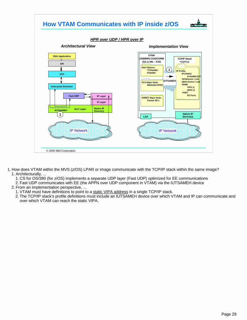
1. How does VTAM within the MVS (z/OS) LPAR or image communicate with the TCP/IP stack within the same image?1. Architecturally, ...
1. CS for OS/390 (for z/OS) implements a separate UDP layer (Fast UDP) optimized for EE communications2. Fast UDP communicates with EE (the APPN over UDP component in VTAM) via the IUTSAMEH device
2. From an implementation perspective, ...1. VTAM must have definitions to point to a static VIPA address in a single TCP/IP stack.2. The TCP/IP stack's profile definitions must include an IUTSAMEH device over which VTAM and IP can communicate and
over which VTAM can reach the static VIPA.
© 2005 IBM Corporation
EE Definition Overview: S192CDRM & S193CDRM
z/OS SEC1
TCPIP Stack'TCPT11'
QDIO
Start Options:TCPNAME=IPADDR=
XCA Major Node:MEDIUM=HPRIPEE Lines/PUs
IP Profile:IPCONFIG
DYNAMICXCFVIPADevice / LinkQDIO Device /LinkHOME
VIPA @QDIO @
PORTEE Ports
SWNET Major Node:Partner EE PUs
IUTSAMEH
VTAMUSIBMWZ.S192CDRM
(SA & NN -- ICN)
1
2
z/OS SEC2
TCPIP Stack'TCPT21'
QDIO
Start Options:TCPNAME=IPADDR=
IP Profile:IPCONFIG
DYNAMICXCFVIPADevice / LinkQDIO Device /LinkHOME
VIPA @QDIO @
PORTEE Ports
SWNET Major Node:Partner EE PUs
VTAMUSIBMWZ.S193CDRM
(NN)
2
IUTSAMEH
1
At each EE Endpoint ...1. Interconnect SNA/APPN with IP VIPA @ via IUTSAMEH Device within single EE
Endpoint using VTAM Start Options, an XCA Major Node, and IP Profile definitions. 2. Provide coding for predefined or dynamic TG to opposite EE Endpoint. Can use a
Switched Net Major Node.
XCA Major Node:MEDIUM=HPRIPEE Lines/PUs
IP@IP@
Page 30
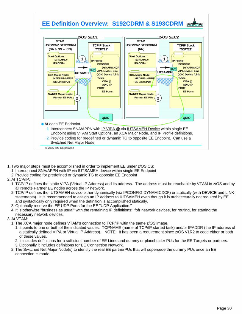
1. Two major steps must be accomplished in order to implement EE under z/OS CS:1. Interconnect SNA/APPN with IP via IUTSAMEH device within single EE Endpoint2. Provide coding for predefined or dynamic TG to opposite EE Endpoint
2. At TCP/IP:1. TCP/IP defines the static VIPA (Virtual IP Address) and its address. The address must be reachable by VTAM in z/OS and by
all remote Partner EE nodes across the IP network.2. TCP/IP defines the IUTSAMEH device either dynamically (via IPCONFIG DYNAMICXCF) or statically (with DEVICE and LINK
statements). It is recommended to assign an IP address to IUTSAMEH even though it is architecturally not required by EE and syntactically only required when the definition is accomplished statically.
3. Optionally reserve the EE UDP Ports for the EE "UDP Application."4. It is otherwise "business as usual" with the remaining IP definitions: fofr network devices, for routing, for starting the
necessary network devices. 3. At VTAM:
1. The XCA major node defines VTAM's connection to TCP/IP witin the same z/OS image.1. It points to one or both of the indicated values: TCPNAME (name of TCP/IP started task) and/or IPADDR (the IP address of
a statically defined VIPA or Virtual IP Address). NOTE: It has been a requirement since z/OS V1R2 to code either or both of these values.
2. It includes definitions for a sufficient number of EE Lines and dummy or placeholder PUs for the EE Targets or partners. 3. Optionally it includes definitions for EE Connection Network.
2. The Switched Net Major Node(s) to identify the real EE partnerPUs that will supersede the dummy PUs once an EE connection is made.
© 2005 IBM Corporation
EE Definition Detail for S192CDRM to S193CDRM
Start Options:TCPNAME=IPADDR=
IP Profile:IPCONFIG
DYNAMICXCFVIPADevice / LinkQDIO Device /LinkHOME
VIPA @QDIO @
PORTEE Ports
IP@
IPCONFIG ... DYNAMICXCF 10.1.1.1 255.255.255.0 1 ;DEVICE GIGQDIO1 MPCIPA NONROUTER AUTORESTART LINK GIGQDIO1 IPAQENET GIGQDIO1 ; DEVICE VDEV2 VIRTUAL 0 LINK VLINK2 VIRTUAL 0 VDEV2 ; HOME 192.168.135.209 VLINK2 172.17.0.209 GIGQDIO1
IP@
IP@
NETID=USIBMWZ,SSCPNAME=S192CDRM,
NODETYPE=NN, CDSERVR=NO, CONNTYPE=APPN, CPCP=NO, HPR=RTP,HPRARB=RESPMODE,...TCPNAME=TCPT11, IPADDR=192.168.135.209,
IP@
XCA Major Node:MEDIUM=HPRIPEE Lines/PUs
SWNET Major Node:Partner EE PUs
EEXCA0 VBUILD TYPE=XCA * EEPORT PORT MEDIUM=HPRIP, X IPTOS=(20,40,80,C0,C0),LIVTIME=10,IPPORT=12000, X SAPADDR=4,SRQRETRY=3,SRQTIME=15, X TGP=EEXTWAN,CAPACITY=100M * EEGRPL1 GROUP DIAL=YES,AUTOGEN=(10,EL1,EP1), X DYNPU=NO,KEEPACT=YES, X CALL=INOUT,ISTATUS=ACTIVE
EEE2SEC2 VBUILD TYPE=SWNET * SWNET MAJOR NODE TO CONNECT TO SEC2 LPAR * EEPUSEC2 PU ADDR=04,NETID=USIBMWZ,TGN=13, X CONNTYPE=APPN,CPCP=YES,CPNAME=S193CDRM, X TGP=EEXTCAMP,CAPACITY=100M,DWINOP=YES * EEPTHS2 PATH IPADDR=172.16.2.121,GRPNM=EEGRPL1, X REDDELAY=30,REDIAL=3
IP@
Page 31
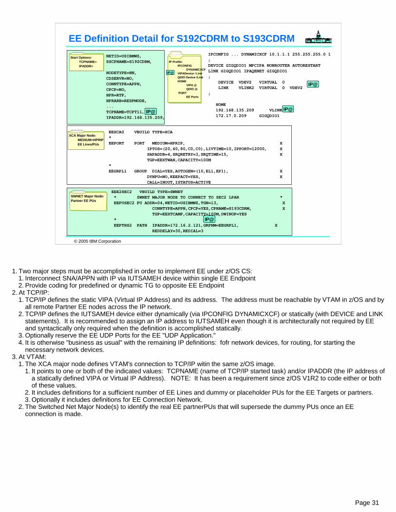
1. Two major steps must be accomplished in order to implement EE under z/OS CS:1. Interconnect SNA/APPN with IP via IUTSAMEH device within single EE Endpoint2. Provide coding for predefined or dynamic TG to opposite EE Endpoint
2. At TCP/IP:1. TCP/IP defines the static VIPA (Virtual IP Address) and its address. The address must be reachable by VTAM in z/OS and by
all remote Partner EE nodes across the IP network.2. TCP/IP defines the IUTSAMEH device either dynamically (via IPCONFIG DYNAMICXCF) or statically (with DEVICE and LINK
statements). It is recommended to assign an IP address to IUTSAMEH even though it is architecturally not required by EE and syntactically only required when the definition is accomplished statically.
3. Optionally reserve the EE UDP Ports for the EE "UDP Application."4. It is otherwise "business as usual" with the remaining IP definitions: fofr network devices, for routing, for starting the
necessary network devices. 3. At VTAM:
1. The XCA major node defines VTAM's connection to TCP/IP witin the same z/OS image.1. It points to one or both of the indicated values: TCPNAME (name of TCP/IP started task) and/or IPADDR (the IP address of
a statically defined VIPA or Virtual IP Address). NOTE: It has been a requirement since z/OS V1R2 to code either or both of these values.
2. It includes definitions for a sufficient number of EE Lines and dummy or placeholder PUs for the EE Targets or partners. 3. Optionally it includes definitions for EE Connection Network.
2. The Switched Net Major Node(s) to identify the real EE partnerPUs that will supersede the dummy PUs once an EE connection is made.

© 2005 IBM Corporation
EE Definition Detail for S193CDRM to S192CDRM
Start Options:TCPNAME=IPADDR=
IP Profile:IPCONFIG
DYNAMICXCFVIPADevice / LinkQDIO Device /LinkHOME
VIPA @QDIO @
PORTEE Ports
IP@
IPCONFIG ... DYNAMICXCF 10.1.1.2 255.255.255.0 1 ;DEVICE GIGQDIO1 MPCIPA NONROUTER AUTORESTART LINK GIGQDIO1 IPAQENET GIGQDIO1 ; DEVICE VDEV2 VIRTUAL 0 LINK VLINK2 VIRTUAL 0 VDEV2 ; HOME 172.16.2.121 VLINK2 172.17.0.121 GIGQDIO1
IP@
IP@
NETID=USIBMWZ,SSCPNAME=S193CDRM,
NODETYPE=NN, CDSERVR=NO, CONNTYPE=APPN, CPCP=NO, HPR=RTP,HPRARB=RESPMODE,...TCPNAME=TCPT21, IPADDR=172.16.2.121,
IP@
XCA Major Node:MEDIUM=HPRIPEE Lines/PUs
SWNET Major Node:Partner EE PUs
EEXCA0 VBUILD TYPE=XCA * EEPORT PORT MEDIUM=HPRIP, X IPTOS=(20,40,80,C0,C0),LIVTIME=10,IPPORT=12000, X SAPADDR=4,SRQRETRY=3,SRQTIME=15, X TGP=EEXTWAN,CAPACITY=100M * EEGRPL1 GROUP DIAL=YES,AUTOGEN=(10,EL1,EP1), X DYNPU=NO,KEEPACT=YES, X CALL=INOUT,ISTATUS=ACTIVE
EEE2SEC1 VBUILD TYPE=SWNET * SWNET MAJOR NODE TO CONNECT TO SEC1 LPAR * EEPUSEC1 PU ADDR=04,NETID=USIBMWZ,TGN=13, X CONNTYPE=APPN,CPCP=YES,CPNAME=S192CDRM, X TGP=EEXTCAMP,CAPACITY=100M,DWINOP=YES * EEPTHS1 PATH IPADDR=192.168.135.209,GRPNM=EEGRPL1, X REDDELAY=30,REDIAL=3
IP@
Page 32
1. Two major steps must be accomplished in order to implement EE under z/OS CS:1. Interconnect SNA/APPN with IP via IUTSAMEH device within single EE Endpoint2. Provide coding for predefined or dynamic TG to opposite EE Endpoint
2. At TCP/IP:1. TCP/IP defines the static VIPA (Virtual IP Address) and its address. The address must be reachable by VTAM in z/OS and by
all remote Partner EE nodes across the IP network.2. TCP/IP defines the IUTSAMEH device either dynamically (via IPCONFIG DYNAMICXCF) or statically (with DEVICE and LINK
statements). It is recommended to assign an IP address to IUTSAMEH even though it is architecturally not required by EE and syntactically only required when the definition is accomplished statically.
3. Optionally reserve the EE UDP Ports for the EE "UDP Application."4. It is otherwise "business as usual" with the remaining IP definitions: fofr network devices, for routing, for starting the
necessary network devices. 3. At VTAM:
1. The XCA major node defines VTAM's connection to TCP/IP witin the same z/OS image.1. It points to one or both of the indicated values: TCPNAME (name of TCP/IP started task) and/or IPADDR (the IP address of
a statically defined VIPA or Virtual IP Address). NOTE: It has been a requirement since z/OS V1R2 to code either or both of these values.
2. It includes definitions for a sufficient number of EE Lines and dummy or placeholder PUs for the EE Targets or partners. 3. Optionally it includes definitions for EE Connection Network.
2. The Switched Net Major Node(s) to identify the real EE partnerPUs that will supersede the dummy PUs once an EE connection is made.
© 2005 IBM Corporation
EE Definition Detail for S193CDRM (SEC2) to Cisco
Start Options:TCPNAME=IPADDR=
XCA Major Node:MEDIUM=HPRIPEE Lines/PUs
SWNET Major Node:Partner EE PUs
IP Profile:IPCONFIG
DYNAMICXCFVIPADevice / LinkQDIO Device /LinkHOME
VIPA @QDIO @
PORTEE Ports
IP@
IPCONFIG ... DYNAMICXCF 10.1.1.2 255.255.255.0 1 ;DEVICE GIGQDIO1 MPCIPA NONROUTER AUTORESTART LINK GIGQDIO1 IPAQENET GIGQDIO1 ; DEVICE VDEV2 VIRTUAL 0 LINK VLINK2 VIRTUAL 0 VDEV2 ; HOME 172.16.2.121 VLINK2 172.17.0.121 GIGQDIO1
IP@
IP@
NETID=USIBMWZ,SSCPNAME=S193CDRM,
NODETYPE=NN, CDSERVR=NO, CONNTYPE=APPN, CPCP=NO, HPR=RTP,HPRARB=RESPMODE,...TCPNAME=TCPT21, IPADDR=172.16.2.121, ...
IP@
EEXCA0 VBUILD TYPE=XCA * EEPORT PORT MEDIUM=HPRIP, X IPTOS=(20,40,80,C0,C0),LIVTIME=10,IPPORT=12000, X SAPADDR=4,SRQRETRY=3,SRQTIME=15, X TGP=EEXTWAN,CAPACITY=100M * EEGRPL1 GROUP DIAL=YES,AUTOGEN=(10,EL1,EP1), X DYNPU=NO,KEEPACT=YES, X CALL=INOUT,ISTATUS=ACTIVE
EE006BMN VBUILD TYPE=SWNET * SWNET MAJOR NODE TO CONNECT TO CISCO 4006B SNASW * EEPU006B PU ADDR=04,NETID=USIBMWZ,TGN=3, X CONNTYPE=APPN,CPCP=YES,CPNAME=CPREE4, X ANS=CONTINUE,TGP=EEXTWAN,CAPACITY=100M, X DWINOP=YES EEPH006B PATH IPADDR=192.168.135.182,GRPNM=EEGRPL1, X REDDELAY=30,REDIAL=3
IP@
DLU
R-D
LUS
CP
- CP
CISCO 4500
USIBMWZ.CPREE4Loopback
192.168.135.182
EN,BEX
DLUR
USIBMWZ.S193CDRMDLUSNNS
NN TCPT21
172.16.2.121 VLINK1
EE L
ink
Tg 3
SNA over LAN:CSSNET.CPGWPCOM
Page 33
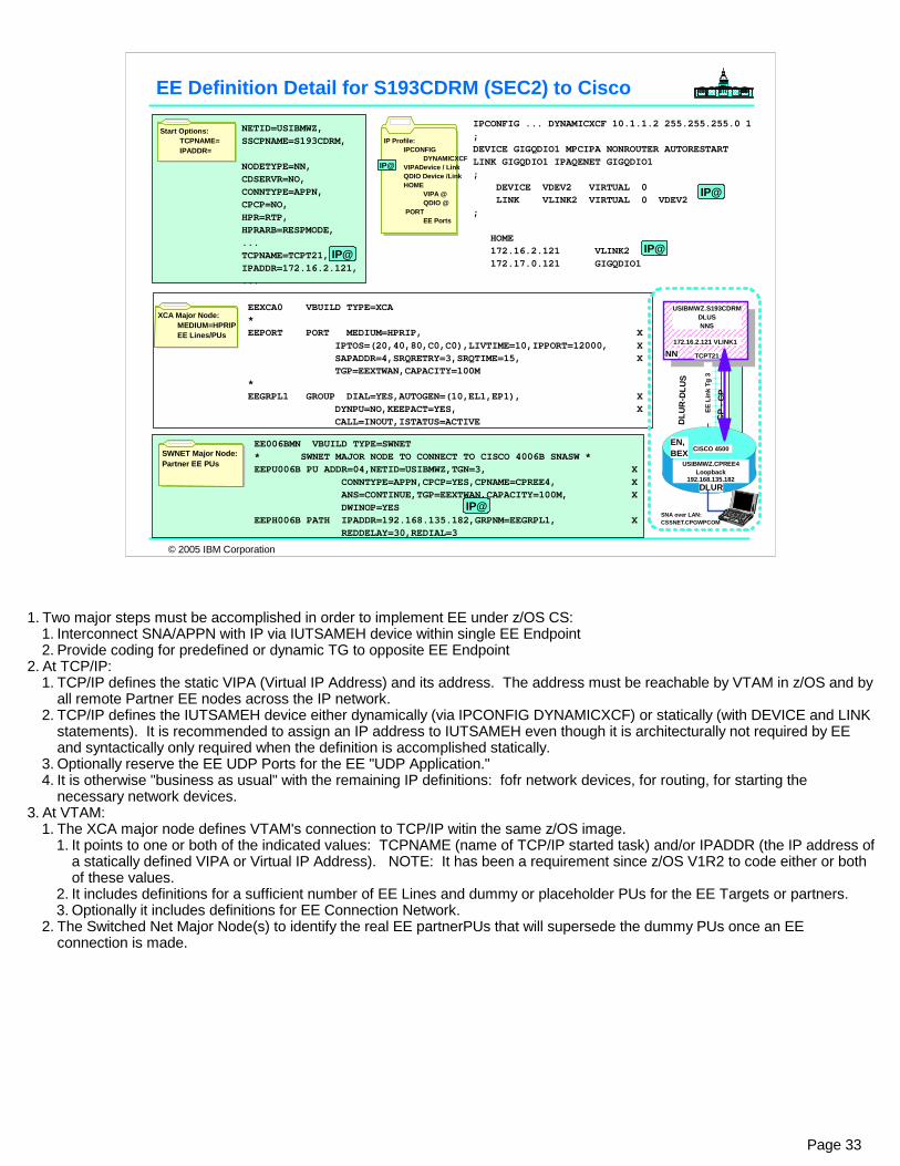
1. Two major steps must be accomplished in order to implement EE under z/OS CS:1. Interconnect SNA/APPN with IP via IUTSAMEH device within single EE Endpoint2. Provide coding for predefined or dynamic TG to opposite EE Endpoint
2. At TCP/IP:1. TCP/IP defines the static VIPA (Virtual IP Address) and its address. The address must be reachable by VTAM in z/OS and by
all remote Partner EE nodes across the IP network.2. TCP/IP defines the IUTSAMEH device either dynamically (via IPCONFIG DYNAMICXCF) or statically (with DEVICE and LINK
statements). It is recommended to assign an IP address to IUTSAMEH even though it is architecturally not required by EE and syntactically only required when the definition is accomplished statically.
3. Optionally reserve the EE UDP Ports for the EE "UDP Application."4. It is otherwise "business as usual" with the remaining IP definitions: fofr network devices, for routing, for starting the
necessary network devices. 3. At VTAM:
1. The XCA major node defines VTAM's connection to TCP/IP witin the same z/OS image.1. It points to one or both of the indicated values: TCPNAME (name of TCP/IP started task) and/or IPADDR (the IP address of
a statically defined VIPA or Virtual IP Address). NOTE: It has been a requirement since z/OS V1R2 to code either or both of these values.
2. It includes definitions for a sufficient number of EE Lines and dummy or placeholder PUs for the EE Targets or partners. 3. Optionally it includes definitions for EE Connection Network.
2. The Switched Net Major Node(s) to identify the real EE partnerPUs that will supersede the dummy PUs once an EE connection is made.
© 2005 IBM Corporation
! interface Loopback0 ip address 192.168.135.182 255.255.255.252 ! snasw pdlog informationsnasw dlctracesnasw cpname USIBMWZ.CPREE4snasw dlus USIBMWZ.S193CDRMsnasw port ETH1 Ethernet1snasw port HPRIP hpr-ip Loopback0 vnname USIBMWZ.HPRIP1 no-limres ldlc 25 15 3snasw link UPL4006B port HPRIP ip-dest 172.16.2.121
DL U
R- D
LUS
CP
- CP
CISCO 4500
USIBMWZ.CPREE4Loopback
192.168.135.182
EN,BEX
DLUR
USIBMWZ.S193CDRMDLUSNNS
NN TCPT21
172.16.2.121 VLINK1
EE L
ink
Tg 3
SNA over LAN:CSSNET.CPGWPCOM
SNASWitch Statements at CPREE4Create EE Definitions at CISCO SNASwitch Router "CPREE4" (snaswitch statements)
cpname of CPREE4dlus is S193CDRMports for SNA traffic:
Ethernet adapter to workstationEE endpoint (HPRIP)EE link UPL4006B at Loopback0 (address of 192.168.135.182) points to partner at 172.16.2.121
ETH1
EE port/link
Step 2: Identify opposite EE Endpoint: "snaswitch link"
Step 1: Interconnect SNA and IP: "snaswitch port"
1
2
Page 34
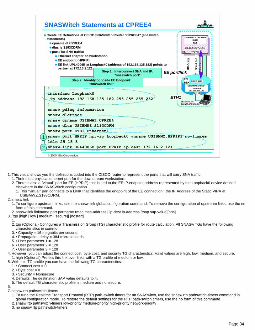
1. This visual shows you the definitions coded into the CISCO router to represent the ports that will carry SNA traffic.1. Thefre is a physical ethernet port for the downstream workstation.2. There is also a "virtual" port for EE (HPRIP) that is tied to the EE IP endpoint address represented by the Loopback0 device defined
elsewhere in the SNASWitch configuration.1. This "virtual" port connects to a LINK that identifies the endpoint of the EE connection: the IP Address of the Static VIPA at
USIBMWZ.S193CDRM.2. snasw link
1. To configure upstream links, use the snasw link global configuration command. To remove the configuration of upstream links, use the no form of this command.
2. snasw link linkname port portname rmac mac-address | ip-dest ip-address [rsap sap-value][nns]3. [tgp [high | low | medium | secure]] [nostart]
1.2. tgp (Optional) Configures a Transmission Group (TG) characteristic profile for route calculation. All SNASw TGs have the following
characteristics in common:3. • Capacity = 16 megabits per second4. • Propagation delay = 384 microseconds5. • User parameter 1 = 1286. • User parameter 2 = 1287. • User parameter 3 = 128
4. However, you can adjust the connect cost, byte cost, and security TG characteristics. Valid values are high, low, medium, and secure.1. high (Optional) Prefers this link over links with a TG profile of medium or low.
5. With this TG profile you can have the following TG characteristics:1. • Connect cost = 02. • Byte cost = 03. • Security = Nonsecure4. Defaults The destination SAP value defaults to 4.5. The default TG characteristic profile is medium and nonsecure.
6.7. snasw rtp pathswitch-timers
1. To tune the Realtime Transport Protocol (RTP) path-switch timers for an SNASwitch, use the snasw rtp pathswitch-timers command in global configuration mode. To restore the default settings for the RTP path-switch timers, use the no form of this command.
2. snasw rtp pathswitch-timers low-priority medium-priority high-priority network-priority3. no snasw rtp pathswitch-timers

© 2005 IBM Corporation
Appendix:EE Coding for z/OS to z/OSConsole Logs of Activation
this day of , 199 ,
by Gwendolyn J. Dente, IBM Advanced Technical Support
Graduation Graduation CCERTIFICATEERTIFICATE
PPRESENTED TO:RESENTED TO:
We appreciate your attendance at this session. In recognition of the enthusiastic attention you paid
during this presentation, we gladly present this certificate of completion.
EXPO 2005 Attendee
Page 35

© 2005 IBM Corporation
USIBMWZ.S100CDRM
CISCO 4500 CISCO 4500
IP Network: Logical View
GBE-QDIO
CISCO 2610
USIBMWZ.CPREE3Loopback
192.168.135.181
CISCO 4500
USIBMWZ.CPREE4Loopback
192.168.135.182
Private Addresses
OSPF Routes
192.168.25.34 VLINK1
TCPIPB
P R I V A T E1
192.168.135.209 VLINK1
USIBMWZ.S192CDRMUSIBMWZ.S193CDRM
DLUSNNSIsolated
AddressesStatic Routes
TCPT11 TCPT21
172.16.2.121 VLINK1
PRIVATE2
Create EE Definitions at S192CDRMVTAM Start OptionsPROFILE for TCP/IPXCA Major NodeSWNET Major Node
Create EE Definitions at S193CDRMVTAM Start OptionsPROFILE for TCP/IPXCA Major NodeSWNET Major Node
Verify that Control Sessions (CP-CP Sessions) are started. Verify that LU-LU Sessions between S193CDRM and CPREE4 can be started
Page 36
1. This is a logical view of an entire test network that we have built. It does not show you every connection, but rather the IP addresses that we are dealing with for Enterprise Extender.
2. Within a dotted rectangle you see the section of the entire configuration that we deal with in the next portion of this presentation. 3. Although we depict USIBMWZ.S100CDRM in this visual, we will focus for the purposes of this one-hour presentation only on the relationships
among USIBMWZ.S192CDRM, USIBMWZ.S193CDERM, and the CISCO Router, USIBMWZ.CPREE4.4. The next few pages will include some of the definitions for EE in these notes. They are for your reference, as a prerequisite for this topic is that
you already know how to code for Enterprise Extender.5. Definition at S192CDRM to Connect to S193CDRMEE2SEC2 VBUILD TYPE=SWNET * * CHANGE RECORD WHO? WHEN? * --------------------------------- ------ ----* ADDED NEW IN V1R4: DWINOP, REDDELAY, REDIAL GJD 01/19/04 * * FOR TESTING OMIT DWACT=YES ON PU GJD 01/19/04 * * ------------------------------------------------------------- * * EEPUSEC2 PU ADDR=04,NETID=USIBMWZ,TGN=13, CONNTYPE=APPN,CPCP=YES,CPNAME=S193CDRM, ANS=CONTINUE,TGP=EEXTCAMP,CAPACITY=100M, DWINOP=YES * EEPHSEC2 PATH IPADDR=172.16.2.121,GRPNM=EEGRPL1, REDDELAY=30,REDIAL=3
1. Definition at S193CDRM to Connect to Router "CPREE4"
EE006BMN VBUILD TYPE=SWNET * EEPU006B PU ADDR=04,NETID=USIBMWZ,TGN=3, CONNTYPE=APPN,CPCP=YES,CPNAME=CPREE4, ANS=CONTINUE,TGP=EEXTCAMP,CAPACITY=100M, DWINOP=YES EEPH006B PATH IPADDR=192.168.135.182,GRPNM=EEGRPL1, REDDELAY=30,REDIAL=3

© 2005 IBM Corporation
IPCONFIG ... DynamicXCF 10.1.1.1 255.255.255.0 1; ; DEVICES and LINKS for TEST Network...DEVICE GIGQDIO1 MPCIPA PRIROUTER AUTORESTART LINK GIGQDIO1 IPAQENET GIGQDIO1 ; ; DEVICE and LINK for Virtual Devices (VIPA): ; DEVICE VDEV1 VIRTUAL 0 LINK VLINK1 VIRTUAL 0 VDEV1 ; START GIGQDIO1...AUTOLOG 5 OMPRT11 ; OMPROUTE ... ENDAUTOLOG ; HOME 192.168.135.209 VLINK1 ; VIPA ... 172.17.0.101 GIGQDIO1 ; Ethernet Adapter ;PORT ... 12000 UDP CSSVTAM ; LDLC 12001 UDP CSSVTAM ; NETWORK PRIORITY 12002 UDP CSSVTAM ; HIGH PRIORITY 12003 UDP CSSVTAM ; MEDIUM PRIORITY 12004 UDP CSSVTAM ; LOW PRIORITY
TCP/IP Profile for EE: S192CDRM
Step 1: Interconnect SNA and IP
IP@
IP@
GBE-QDIO
192.168.135.209 VLINK1
USIBMWZ.S192CDRMUSIBMWZ.S193CDRM
DLUSNNS
TCPT11 TCPT21
172.16.2.121 VLINK1
Page 37
1. This is a subset of the entire Profile for the TCP/IP stack.2. DYNAMICXCF builds the IUTSAMEH device. This is the recommended approach over an older method -- often illustrated in the
original EE publications -- which defines a "DEVICE IUTSAMEH" with a link under it.3. A QDIO device is the IP connection to the remote network -- any IP device would have sufficed.The static VIPA is required for
EE connectivity.4. The external QDIO device is started; the DYNAMICXCF device and the VIPA are automatically started without a START
statement.5. The HOME statement identifies the IP addresses of LINKS. With DYNAMICXCF the HOME address s dynamically built and is
not coded into the HOME list. The static VIPA is the endpoint of the EE connection and is marked with "IP@."1. We recommend that EE be assigned its own Static VIPA address. Other VIPAs can be used for other types of IP activity.
However, a single IP address can be used for both types of activity, although this makes problem determination and management more complex.
2. There is no maximum for static VIPA interfaces, but the maximum number of Dynamic VIPA interfaces is 1024. (There is a maximum of 255 devices per TCP/IP stack, excluding VIPAs.)
6. Any kind of routing will work for EE, although we include here static routing. Dynamic routing - preferably OSPF -- is recommended.
7. We reserve the EE ports although this was not necessary. Note that the third column requires the name of the VTAM Start Procedure. This is usually NET, but on this particular MVS image the procname is CSSVTAM.

© 2005 IBM Corporation
NETID=USIBMZ,SSCPNAME=S192CDRM,NODETYPE=NN, CDSERVR=YES, CONNTYPE=LEN, CPCP=NO, SORDER=APPNFRST, SSEARCH=YES, CDRDYN=YES, DYNLU=YES, DYNADJCP=YES,ISTCOSDF=INDLU,APPNCOS=#CONNECT,HPR=RTP, HPRARB=RESPMODE, HPRPST=(8M,4M,2M,1M),PSRETRY=(60,120,180,240), ... TCPNAME=TCPT11, IPADDR=192.168.135.209, XCFINIT=YES, XNETALS=YES,BN=YES,BNORD=PRIORITY, ...
D NET,VTAMOPTS,FUNCTION=APPNCHAR IST1188I VTAM CSV1R6 STARTED AT 10:20:49 ON 09/16/04 365 IST1349I COMPONENT ID IS 5695-11701-160 IST1348I VTAM STARTED AS NETWORK NODE
VTAM Start Options: S192CDRM
IP@
Step 1: Interconnect SNA and IP
GBE-QDIO
192.168.135.209 VLINK1
USIBMWZ.S192CDRMUSIBMWZ.S193CDRM
DLUSNNS
TCPT11 TCPT21
172.16.2.121 VLINK1
Page 38
1. VTAM specifies several Start Options. One or both of the following two options must be specified, although this has not always been a requirement.1. TCPNAME = the started task name of the TCP/IP stack2. IPADDR = the static VIPA address (on this same LPAR) that is used for Enterprise Extender
2. APPN/HPR is a prerequisite to EE; we do not review everything necessary to implement APPN/HPR, trying to focus on EE, although you notice above that VTAM has been started as a Network Node, and is also an ICN. HPR is enabled. Someone in your organization should have implementation experience with VTAM/APPN and should preferably have attended the course G3643: "VTAM/APPN Implementation."1. Note above that APPN has been enabled internally by specifying "NODETYPE=NN" and that HPR is also enabled with
"HPR=RTP." However, APPN communications have been globally disabled because of CPCP=NO and CONNTYPE=LEN. On an individual basis these options can be enabled as appropriate for individual link stations or PUs at the end of an EE link. Note that some companies would enable APPN globally because they either have a small network with no need for an understanding of the tight controls available in APPN or because even with their large network they understand how to deal with the searching and APPNCOS resolution in a large APPN network.
2. The default for HPRARB, a VTAM START OPTION, is RESPMODE, and indicates a new ARB (adaptive rate-based congestion control) algorithm which provides more fairness when HPR is sharing the network with IP than does the original algorithm. HPRARB=BASE may be coded to use the original algorithm. HPRARB=RESPMODE is the new algorithm introduced in V2R6 via APAR OW36113.

© 2005 IBM Corporation
EEXCA0 VBUILD TYPE=XCA * -------------------------------------------------------------- * * XCA FOR ENTERPRISE EXTENDER (no VRN) * * -------------------------------------------------------------- * EEPORT PORT MEDIUM=HPRIP, X IPTOS=(20,40,80,C0,C0),LIVTIME=10,IPPORT=12000, X SAPADDR=4,SRQRETRY=3,SRQTIME=15, X TGP=EEXTWAN,CAPACITY=100M* EEGRPL1 GROUP DIAL=YES,AUTOGEN=(10,EL1,EP1),DYNVNPFX=V1, X DYNPU=NO,KEEPACT=YES, X CALL=INOUT,ISTATUS=ACTIVE X
EE Detail - XCA at S192CDRM
V NET,ACT,ID=EEXCA0
DYNPU=NO recommended until z/OS V1R5.
Step 1: Interconnect SNA and IP
KEEPACT=YES (V1R4)
Page 39
1. The MEDIUM keyword on the PORT statement set to HPRIP indicates that this is the XCA Major Node for EE.2. The GROUP defines a group of automatically generated LINEs/PUs. One LINE/PU is needed for each concurrently active EE partner accessed through the IP
network, LINEs/PUs from this GROUP can also be utilized for dynamically activated connection network links, as well as for predefined links, such as that coded in the Switched Major Node.
3. When the XCA Major Node is activated, VTAM connects to TCP/IP using the TCPNAME and IPADDR coded on the VTAM Start Options.4. With V2R10 or V2R8 (with APARs OW43814 and PQ38173) or higher, the XCA Major Node can be activated prior to TCP/IP. 5. KEEPACT=YES is the default at V1R4. It allows the implementer to insert the EE XCA major node into the VTAM Configuration List (ATCCONxx) without having to
redrive the activation of the lines again once TCP/IP is running. In the event of certain failures (TCP/IP stack termination or unavailability), it will redrive the activation of the EE links. (See later section of this presentation on "Some V1R4 Enhancements to EE.")
6. IPTOS specifies the Type of Service use for TCP/IP communication. Usually this is alled to default. Default values will be used for each Type of Service value which is not entered. The first value (20) is represented as low, the second value (40) as medium, the third value (80) as high, the fourth value (C0) as network, and the last value (C0) as signal for Type of Service. Note: TOS values need to be consistent throughout the network.
7. The timers (LIVTIME, SRQTIME,SRQRETRY) govern how long an interval to wait before assuming the Enterprise Extender link is inoperative. In this example they are coded using the default values, which may be elongated to decrease EE's senstivity to long routing convergence times and disruptions in the IP network.
8. IPPORT specifies the first number of an ascending sequence of five consecutive numbers that describe the ports used to transmit signal, network, high, medium, and low priority data, respectively. Usually this is alled to default.
9. TGP specifies the name of a TG profile definition. The characteristics of the TG profile (along with any modifiers) become the characteristics of the Connection network PU. If TGP is not specified or has not been activated when the PU becomes active, default TG characteristics are assigned. This TGP definition affects ONLY VRN PUs and not SWNET PUs.
10. CAPACITY specifies the effective capacity of the link that comprises the TG. When coded in the XCA Major Node it modifies the TG characteristics for the VRN PUs only. Specify the value in either Kb per second (for example, 100K) or Mb per second (for example, 100M). This number approximates the bits per second that the link can transmit (the transmission rate of the link, times the maximum load factor expressed as a percentage).
11. VNNAME specifies a 1-17 character network-qualified CPNAME for the connection network. VNNAME is reported to the network topology as a virtual node and is treated as an adjacent CP to this node. The NETID of the SSCP that owns the connection network (the NETID of the host) is used. On this page we ignore connection network for now and address this concept later,
12. VNGROUP specifies the name of the logical GROUP containing dial-out links available for use on the connection network named on the VNNAME operand.13. AUTOGEN specifies the number of VTAM-generated LINE and PU statements. Code a decimal value in the range 1-65536. Values between 4097 and 65536 may
only be entered when MEDIUM=HPRIP is specified for the group. This value is required. Here we have also specified seed values ("prefixes") for the generated LINE and dummy PUnames.
14. DYNVNPFX specifies a two character prefix that is used to generate the names for dynamic connection network PUs. This prefix will be used if DYNVNPFX is not coded on the virtual node GROUP definition statement. The PU names will take the format ppxxxxxx, where xxxxxx is a unique value which is generated and concatenated to the specified prefix pp to create the eight character PU name. When the DYNVNPFX start option is not specified, the default value is the three character prefix CNV. The PU names will then take the format CNVxxxxx, where xxxxx is a unique value which is generated and concatenated to the default prefix to create the eight character PU name.
15. DYNPU specifies whether a PU is to be dynamically allocated when the calling PU cannot be identified during a switched call-in operation. DYNPU applies to APPN and subarea PUs. A PU created by the DYNPU operand will use the switched major node PU operand defaults, except for the following operands which will use the values noted: MAXOUT=8, ANS=CONT, DISCNT=(YES,F), DYNADJCP=YES
1. These default values can be problematical unless they are overridden via the Configuration Services XID exit (ISTEXCCS) or through a V1R5 Model Major Node enhancement of DYNTYPE=EE. This point is covered in more detail towards the end of the presentation.

© 2005 IBM Corporation
EE2SEC2 VBUILD TYPE=SWNET * -------------------------------------------------------------- * * SWNET MAJOR NODE TO CONNECT TO SEC2 LPAR * * -------------------------------------------------------------- * * EEPUSEC2 PU ADDR=04,NETID=USIBMWZ,TGN=13, X CONNTYPE=APPN,CPCP=YES,CPNAME=S193CDRM, X TGP=EEXTCAMP,CAPACITY=100M,DWINOP=YES * EEPTHS2 PATH IPADDR=172.16.2.121,GRPNM=EEGRPL1, X REDDELAY=30,REDIAL=3
EE Detail - SWNET: S192CDRM to S193CDRM
Step 2: Identify opposite EE Endpoint
optional - for dialout only
V NET,DIAL,ID=EEPUSEC2
IP@
DWINOP=YES, etc. (V1R4)
TGN = optional
Page 40
1. The Switched Major node identifies an APPN node with EE functions that is the other end of the TG. If the z/OS side is dialing out to the EE partner, code a PATH and use either the HOSTNAME or the IPADDR of the remote host.1. NETID specifies a 1-8 character network identifier. It represents part of the Fully Qualified name of a node.2. Specifying a TG number is completely optional. It is done here because some shops like to filter on TG number for network
management purposes. They also use different APPN TG numbers in order to distinguish among different types o links. 3. CONNTYPE=APPN overrides the VTAM Start Option setting or it can be used as documentation if APPN is already the default. 4. CPCP=YES overrides the VTAM Start Option setting or it can be used as documentation if it is already the default. It enables
the LINE/PU for CP-CP session capability.5. CPNAME specifies the control point (CP) name of a type 2.1 peripheral node. To dial in, a type 2.1 peripheral node on a
switched line requires either CPNAME or both IDBLK and IDNUM on the PU definition statement. However, you can code all three operands.
6. TGP specifies the name of a TG profile definition. The characteristics of the TG profile (along with any modifiers) become the characteristics of the Switched PU. If TGP is not specified or has not been activated when the PU becomes active, default TG characteristics are assigned.
7. CAPACITY specifies the effective capacity of the link that comprises the TG. Coded her it modifies the TG characteristics if the switched PU. Specify the value in either Kb per second (for example, 100K) or Mb per second (for example, 100M). This number approximates the bits per second that the link can transmit (the transmission rate of the link, times the maximum load factor expressed as a percentage).
8. If the remote host is a z/OS node, the address (IPADDR) is the static VIPA designated for EE at the remote site. If the remote node is not z/OS, the IPADDR is the IP address at the remote node that has been asslociated with the EE function.
9. GRPNM provides the name of a GROUP definition statement in the XCA Major Node that defines a group of EE LINES.2. If the Switched Major Node is coded for dial-out (PATH definition, as shown) and DWACT=YES is specified, activate the Switched
Major Node after the XCA Major Node is active unless you are at z/OS V1R4 or higher. Prior to z/OS V1R4 you probably don't want to place the major node in the VTAM Configuration list (ATCCONxx), because , since TCP/IP is not running at VTAM start, the DIALOUT triggered by DWACT will fail and will not be retried unless you have built in an automation process. If you are at V1R4 you may place this Major Node in the ATCCONxx member of VTAMLST but include the DWINOP operand with the REDDELAY and REDIAL parameters. (See information later in this presentation on "Some V1R4 Enhancements to EE.")
3. If dial-out is coded, but DWACT is not, or if the Switched Major node is activated before the XCA Major Node, use the VARY DIAL command -- illustrated on the bottom.
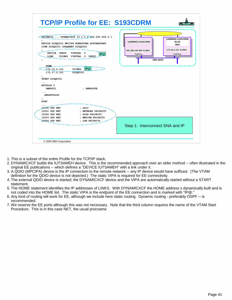
© 2005 IBM Corporation
IPCONFIG ... DYNAMICXCF 10.1.1.2 255.255.255.0 1 ;DEVICE GIGQDIO1 MPCIPA NONROUTER AUTORESTART LINK GIGQDIO1 IPAQENET GIGQDIO1 ; DEVICE VDEV2 VIRTUAL 0 LINK VLINK2 VIRTUAL 0 VDEV2 ; HOME 172.16.2.121 VLINK2 172.17.0.121 GIGQDIO1 ;START GIGQDIO1...AUTOLOG 5 OMPRT21 ; OMPROUTE ... ENDAUTOLOG ;PORT ...12000 UDP NET ; LDLC 12001 UDP NET ; NETWORK PRIORITY 12002 UDP NET ; HIGH PRIORITY 12003 UDP NET ; MEDIUM PRIORITY 12004 UDP NET ; LOW PRIORITY
TCP/IP Profile for EE: S193CDRM
Step 1: Interconnect SNA and IP
IP@
IP@
GBE-QDIO
192.168.135.209 VLINK1
USIBMWZ.S192CDRMUSIBMWZ.S193CDRM
DLUSNNS
TCPT11 TCPT21
172.16.2.121 VLINK1
Page 41
1. This is a subset of the entire Profile for the TCP/IP stack.2. DYNAMICXCF builds the IUTSAMEH device. This is the recommended approach over an older method -- often illustrated in the
original EE publications -- which defines a "DEVICE IUTSAMEH" with a link under it.3. A QDIO (MPCIPA) device is the IP connection to the remote network -- any IP device would have sufficed. (The VTAM
definition for the QDIO device is not depicted.) The static VIPA is required for EE connectivity.4. The external QDIO device is started; the DYNAMICXCF device and the VIPA are automatically started without a START
statement.5. The HOME statement identifies the IP addresses of LINKS. With DYNAMICXCF the HOME address s dynamically built and is
not coded into the HOME list. The static VIPA is the endpoint of the EE connection and is marked with "IP@."6. Any kind of routing will work for EE, although we include here static routing. Dynamic routing - preferably OSPF -- is
recommended.7. We reserve the EE ports although this was not necessary. Note that the third column requires the name of the VTAM Start
Procedure. This is in this case NET, the usual procname.
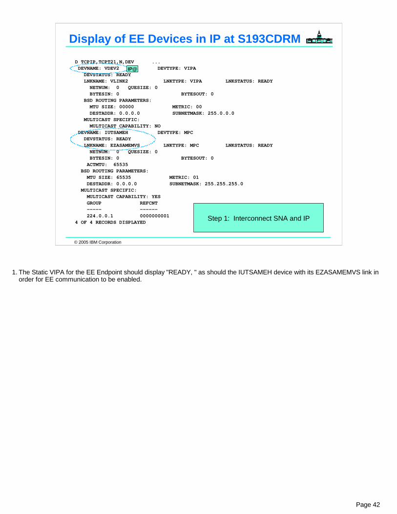
© 2005 IBM Corporation
D TCPIP,TCPT21,N,DEV ... DEVNAME: VDEV2 DEVTYPE: VIPA DEVSTATUS: READY LNKNAME: VLINK2 LNKTYPE: VIPA LNKSTATUS: READY NETNUM: 0 QUESIZE: 0 BYTESIN: 0 BYTESOUT: 0 BSD ROUTING PARAMETERS: MTU SIZE: 00000 METRIC: 00 DESTADDR: 0.0.0.0 SUBNETMASK: 255.0.0.0 MULTICAST SPECIFIC: MULTICAST CAPABILITY: NO DEVNAME: IUTSAMEH DEVTYPE: MPC DEVSTATUS: READY LNKNAME: EZASAMEMVS LNKTYPE: MPC LNKSTATUS: READY NETNUM: 0 QUESIZE: 0 BYTESIN: 0 BYTESOUT: 0 ACTMTU: 65535 BSD ROUTING PARAMETERS: MTU SIZE: 65535 METRIC: 01 DESTADDR: 0.0.0.0 SUBNETMASK: 255.255.255.0 MULTICAST SPECIFIC: MULTICAST CAPABILITY: YES GROUP REFCNT ----- ------ 224.0.0.1 0000000001 4 OF 4 RECORDS DISPLAYED
Display of EE Devices in IP at S193CDRM
Step 1: Interconnect SNA and IP
IP@
Page 42
1. The Static VIPA for the EE Endpoint should display "READY, " as should the IUTSAMEH device with its EZASAMEMVS link in order for EE communication to be enabled.
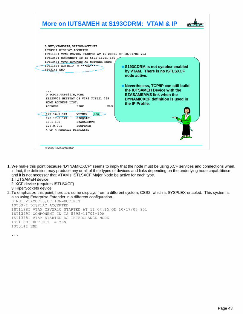
© 2005 IBM Corporation
D NET,VTAMOPTS,OPTION=XCFINIT IST097I DISPLAY ACCEPTED IST1188I VTAM CSV1R6 STARTED AT 15:28:06 ON 10/01/04 764 IST1349I COMPONENT ID IS 5695-11701-160 IST1348I VTAM STARTED AS NETWORK NODE IST1189I XCFINIT = ***NA*** IST314I END
More on IUTSAMEH at S193CDRM: VTAM & IP
...D TCPIP,TCPT21,N,HOME EZZ2500I NETSTAT CS V1R4 TCPT21 768 HOME ADDRESS LIST: ADDRESS LINK FLG ...172.16.2.121 VLINK2 172.17.0.121 GIGQDIO1 10.1.1.2 EZASAMEMVS 127.0.0.1 LOOPBACK 4 OF 4 RECORDS DISPLAYED
S193CDRM is not sysplex-enabled by VTAM. There is no ISTLSXCF node active.
Nevertheless, TCP/IP can still build the IUTSAMEH Device with the EZASAMEMVS link when the DYNAMICXCF definition is used in the IP Profile.
IP@
Page 43
1. We make this point because "DYNAMICXCF" seems to imply that the node must be using XCF services and connections when, in fact, the definition may produce any or all of thee types of devices and links depending on the underlying node capabilitiesm and it is not necessar that VTAM's ISTLSXCF Major Node be active for each type.1. IUTSAMEH device2. XCF device (requires ISTLSXCF)3. HiperSockets device
2. To emphasize this point, here are some displays from a different system, CSS2, which is SYSPLEX-enabled. This system is also using Enterprise Extender in a different configuration.D NET,VTAMOPTS,OPTION=XCFINIT IST097I DISPLAY ACCEPTED IST1188I VTAM CSV2R10 STARTED AT 11:04:15 ON 10/17/03 951 IST1349I COMPONENT ID IS 5695-11701-10A IST1348I VTAM STARTED AS INTERCHANGE NODE IST1189I XCFINIT = YES IST314I END
...
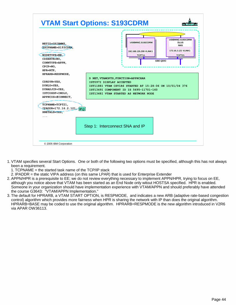
© 2005 IBM Corporation
NETID=USIBMWZ,SSCPNAME=S193CDRM,
NODETYPE=NN, CDSERVR=NO, CONNTYPE=APPN, CPCP=NO, HPR=RTP,HPRARB=RESPMODE,
CDRDYN=YES, DYNLU=YES, DYNADJCP=YES,ISTCOSDF=INDLU,APPNCOS=#CONNECT,... TCPNAME=TCPT21, IPADDR=172.16.2.121, XNETALS=YES,...
D NET,VTAMOPTS,FUNCTION=APPNCHAR IST097I DISPLAY ACCEPTED IST1188I VTAM CSV1R6 STARTED AT 15:28:06 ON 10/01/04 376 IST1349I COMPONENT ID IS 5695-11701-160 IST1348I VTAM STARTED AS NETWORK NODE
VTAM Start Options: S193CDRM
Step 1: Interconnect SNA and IP
IP@
GBE-QDIO
192.168.135.209 VLINK1
USIBMWZ.S192CDRMUSIBMWZ.S193CDRM
DLUSNNS
TCPT11 TCPT21
172.16.2.121 VLINK1
Page 44
1. VTAM specifies several Start Options. One or both of the following two options must be specified, although this has not always been a requirement.1. TCPNAME = the started task name of the TCP/IP stack2. IPADDR = the static VIPA address (on this same LPAR) that is used for Enterprise Extender
2. APPN/HPR is a prerequisite to EE; we do not review everything necessary to implement APPN/HPR, trying to focus on EE, although you notice above that VTAM has been started as an End Node only witout HOSTSA specified. HPR is enabled. Someone in your organization should have implementation experience with VTAM/APPN and should preferably have attended the course G3643: "VTAM/APPN Implementation."
3. The default for HPRARB, a VTAM START OPTION, is RESPMODE, and indicates a new ARB (adaptive rate-based congestion control) algorithm which provides more fairness when HPR is sharing the network with IP than does the original algorithm. HPRARB=BASE may be coded to use the original algorithm. HPRARB=RESPMODE is the new algorithm introduced in V2R6 via APAR OW36113.

© 2005 IBM Corporation
EEXCA0 VBUILD TYPE=XCA * -------------------------------------------------------------- * * XCA FOR ENTERPRISE EXTENDER -- NO CONNECTION NETWORK * * -------------------------------------------------------------- * * EEPORT PORT MEDIUM=HPRIP, X IPTOS=(20,40,80,C0,C0),LIVTIME=10,IPPORT=12000, X SAPADDR=4,SRQRETRY=3,SRQTIME=15, X TGP=EEXTWAN,CAPACITY=100M * EEGRPL1 GROUP DIAL=YES,AUTOGEN=(10,EL1,EP1), X DYNPU=NO,KEEPACT=YES, CALL=INOUT,ISTATUS=ACTIVE
EE Detail - XCA at S193CDRM
Step 1: Interconnect SNA and IP
V NET,ACT,ID=EEXCA0
DYNPU=NO recommended until z/OS V1R5.
KEEPACT=YES (V1R4)
Page 45
1. The MEDIUM keyword on the PORT statement set to HPRIP indicates that this is the XCA Major Node for EE.2. The GROUP defines a group of automatically generated LINEs/PUs. One LINE/PU is needed for each concurrently active EE partner accessed through the IP
network, LINEs/PUs from this GROUP can also be utilized for dynamically activated connection network links, as well as for predefined links, such as that coded in the Switched Major Node.
3. With V2R10 or V2R8 (with APARs OW43814 and PQ38173) or higher, the XCA Major Node can be activated prior to TCP/IP. 4. When the XCA Major Node is activated, VTAM connects to TCP/IP using the TCPNAME and IPADDR coded on the VTAM Start Options.5. IPTOS specifies the Type of Service use for TCP/IP communication. Usually this is alled to default. Default values will be used for each Type of Service value
which is not entered. The first value (20) is represented as low, the second value (40) as medium, the third value (80) as high, the fourth value (C0) as network, and the last value (C0) as signal for Type of Service. Note: TOS values need to be consistent throughout the network.
6. The timers (LIVTIME, SRQTIME,SRQRETRY) govern how long an interval to wait before assuming the Enterprise Extender link is inoperative. In this example they are coded using the default values, which may be elongated to decrease EE's senstivity to long routing convergence times and disruptions in the IP network.
7. IPPORT specifies the first number of an ascending sequence of five consecutive numbers that describe the ports used to transmit signal, network, high, medium, and low priority data, respectively. Usually this is alled to default.
8. TGP specifies the name of a TG profile definition. The characteristics of the TG profile (along with any modifiers) become the characteristics of the Connection network PU. If TGP is not specified or has not been activated when the PU becomes active, default TG characteristics are assigned. This TGP definition affects ONLY VRN PUs and not SWNET PUs.
9. CAPACITY specifies the effective capacity of the link that comprises the TG. When coded in the XCA Major Node it modifies the TG characteristics for the VRN PUs only. Specify the value in either Kb per second (for example, 100K) or Mb per second (for example, 100M). This number approximates the bits per second that the link can transmit (the transmission rate of the link, times the maximum load factor expressed as a percentage).
10. VNNAME specifies a 1-17 character network-qualified CPNAME for the connection network. VNNAME is reported to the network topology as a virtual node and is treated as an adjacent CP to this node. The NETID of the SSCP that owns the connection network (the NETID of the host) is used. On this page we ignore connection network for now and address this concept later,
11. VNGROUP specifies the name of the logical GROUP containing dial-out links available for use on the connection network named on the VNNAME operand.12. AUTOGEN specifies the number of VTAM-generated LINE and PU statements. Code a decimal value in the range 1-65536. Values between 4097 and 65536
may only be entered when MEDIUM=HPRIP is specified for the group. This value is required. Here we have also specified seed values ("prefixes") for the generated LINE and dummy PUnames.
13. DYNVNPFX specifies a two character prefix that is used to generate the names for dynamic connection network PUs. This prefix will be used if DYNVNPFX is not coded on the virtual node GROUP definition statement. The PU names will take the format ppxxxxxx, where xxxxxx is a unique value which is generated and concatenated to the specified prefix pp to create the eight character PU name. When the DYNVNPFX start option is not specified, the default value is the three character prefix CNV. The PU names will then take the format CNVxxxxx, where xxxxx is a unique value which is generated and concatenated to the default prefix to create the eight character PU name.
14. DYNPU specifies whether a PU is to be dynamically allocated when the calling PU cannot be identified during a switched call-in operation. DYNPU applies to APPN and subarea PUs. A PU created by the DYNPU operand will use the switched major node PU operand defaults, except for the following operands which will use the values noted: MAXOUT=8, ANS=CONT, DISCNT=(YES,F), DYNADJCP=YES
1. These default values can be problematical unless they are overridden via the Configuration Services XID exit (ISTEXCCS) or through a V1R5 Model Major Node enhancement of DYNTYPE=EE. This point is covered in more detail towards the end of the presentation.

© 2005 IBM Corporation
V NET,ACT,ID=EEXCA0 IST097I VARY ACCEPTED IST093I EEXCA0 ACTIVE EZZ4324I CONNECTION TO 172.16.2.121 ACTIVE FOR DEVICE IUTSAMEH IST1685I TCP/IP JOB NAME = TCPT21 IST1680I LOCAL IP ADDRESS 172.16.2.121
D NET,E,ID=EEXCA0 IST097I DISPLAY ACCEPTED IST075I NAME = EEXCA0, TYPE = XCA MAJOR NODE 930 IST486I STATUS= ACTIV, DESIRED STATE= ACTIV IST1679I MEDIUM = HPRIP IST1685I TCP/IP JOB NAME = TCPT21 IST1680I LOCAL IP ADDRESS 172.16.2.121 IST1105I RESOURCE STATUS TGN CP-CP TG CHARACTERISTICS IST1106I EEXCA0 AC/R 21 NO 909A0000000000000000209100808080 IST654I I/O TRACE = OFF, BUFFER TRACE = OFF IST1656I VTAMTOPO = REPORT, NODE REPORTED - YES IST170I LINES: IST232I EL1000 ACTIV IST232I EL1001 ACTIV IST232I EL1002 ACTIV IST232I EL1003 ACTIV IST232I EL1004 ACTIV IST232I EL1005 ACTIV IST232I EL1006 ACTIV IST232I EL1007 ACTIV IST232I EL1008 ACTIV IST232I EL1009 ACTIV IST314I END
Activation at S193CDRM of XCA (XCA0)
Generated with "EL1" prefix.
IP@
IP@
GBE-QDIO
192.168.135.209 VLINK1
USIBMWZ.S192CDRMUSIBMWZ.S193CDRM
DLUSNNS
TCPT11 TCPT21
172.16.2.121 VLINK1
v net,act,
d net,e,
Step 1: Interconnect SNA and IP
Page 46
1. Note how the messages generated relate to the VTAM and IP Coding put in place for EE.2. Also note how the XCA Major Node autogens the lines with the prefix identified in the definition on the previous page.

© 2005 IBM Corporation
EE2SEC1 VBUILD TYPE=SWNET * -------------------------------------------------------------- * * SWNET MAJOR NODE TO CONNECT TO SEC1 * * -------------------------------------------------------------- * * EEPUSEC1 PU ADDR=04,NETID=USIBMWZ,TGN=13, X CONNTYPE=APPN,CPCP=YES,CPNAME=S192CDRM, X TGP=EEXTWAN,CAPACITY=100M,DWINOP=YES * EEPTHS1 PATH IPADDR=192.168.135.209,GRPNM=EEGRPL1, X REDDELAY=30,REDIAL=3
EE Detail - SWNET: S193CDRM to S192CDRM
Step 2: Identify opposite EE Endpoint
optional - for dialout only
V NET,DIAL,ID=EEPUSEC1
IP@
DWINOP=YES, etc. (V1R4)
TGN = optional
Page 47
1. The Switched Major node identifies an APPN node with EE functions that is the other end of the TG. If the z/OS side is dialing out to the EE partner, code a PATH and use either the HOSTNAME or the IPADDR of the remote host.1. NETID specifies a 1-8 character network identifier. It represents part of the Fully Qualified name of a node.2. Specifying a TG number is completely optional. It is done here because some shops like to filter on TG number for network
management purposes. They also use different APPN TG numbers in order to distinguish among different types o links. 3. CONNTYPE=APPN overrides the VTAM Start Option setting or it can be used as documentation if APPN is already the
default. 4. CPCP=YES overrides the VTAM Start Option setting or it can be used as documentation if it is already the default. It enables
the LINE/PU for CP-CP session capability.5. CPNAME specifies the control point (CP) name of a type 2.1 peripheral node. To dial in, a type 2.1 peripheral node on a
switched line requires either CPNAME or both IDBLK and IDNUM on the PU definition statement. However, you can code all three operands.
6. TGP specifies the name of a TG profile definition. The characteristics of the TG profile (along with any modifiers) become the characteristics of the Switched PU. If TGP is not specified or has not been activated when the PU becomes active, default TG characteristics are assigned.
7. CAPACITY specifies the effective capacity of the link that comprises the TG. Coded her it modifies the TG characteristics if the switched PU. Specify the value in either Kb per second (for example, 100K) or Mb per second (for example, 100M). This number approximates the bits per second that the link can transmit (the transmission rate of the link, times the maximum load factor expressed as a percentage).
8. If the remote host is a z/OS node, the address (IPADDR) is the static VIPA designated for EE at the remote site. If the remote node is not z/OS, the IPADDR is the IP address at the remote node that has been asslociated with the EE function.
9. GRPNM provides the name of a GROUP definition statement in the XCA Major Node that defines a group of EE LINES.2. If the Switched Major Node is coded for dial-out (PATH definition, as shown) and DWACT=YES is specified, activate the
Switched Major Node after the XCA Major Node is active unless you are able to automate the reactivation process or are at V1R4 and are using the new DWINOP operand.
3. If dial-out is coded, but DWACT is not, or if the Switched Major node is activated before the XCA Major Node, use the VARY DIAL command -- illustrated on the bottom.

© 2005 IBM Corporation
V NET,ACT,ID=EE2SEC1 IST097I VARY ACCEPTED IST093I EEPUSEC1 ACTIVE IST093I EE2SEC1 ACTIVE
V NET,DIAL,ID=EEPUSEC1 IST097I VARY ACCEPTED IST590I CONNECTOUT ESTABLISHED FOR PU EEPUSEC1 ON LINE EL1000 IST1086I APPN CONNECTION FOR USIBMWZ.S192CDRM IS ACTIVE - TGN = 13 IST241I VARY DIAL COMMAND COMPLETE FOR EEPUSEC1 IST1488I ACTIVATION OF RTP CNR00007 AS ACTIVE TO USIBMWZ.S192CDRM IST1488I ACTIVATION OF RTP CNR00008 AS PASSIVE TO USIBMWZ.S192CDRM IST1096I CP-CP SESSIONS WITH USIBMWZ.S192CDRM ACTIVATED
Activation: SWNET from S193CDRM to S192CDRM
GBE-QDIO
192.168.135.209 VLINK1
USIBMWZ.S192CDRMUSIBMWZ.S193CDRM
DLUSNNS
TCPT11 TCPT21
172.16.2.121 VLINK1
v net,act,
v net,dial,
Step 2: Identify opposite EE Endpoint
Page 48

© 2005 IBM Corporation
D NET,E,ID=EEPUSEC1 IST097I DISPLAY ACCEPTED IST075I NAME = EEPUSEC1, TYPE = PU_T2.1 214 IST486I STATUS= ACTIV, DESIRED STATE= ACTIV IST1043I CP NAME = S192CDRM, CP NETID = USIBMWZ, DYNAMIC LU = YES IST1589I XNETALS = YES IST1105I RESOURCE STATUS TGN CP-CP TG CHARACTERISTICS IST1106I EEPUNM2 AC/R 13 YES 98430000000000000000209100808080 IST1482I HPR = RTP - OVERRIDE = N/A - CONNECTION = YES IST1510I LLERP = NOTPREF - RECEIVED = NOTALLOW IST1680I LOCAL IP ADDRESS 172.16.2.121 IST1680I REMOTE IP ADDRESS 192.168.135.209 IST136I SWITCHED SNA MAJOR NODE = EE2SEC1 IST081I LINE NAME = EL1000, LINE GROUP = EEGRPL1, MAJNOD = EEXCA0 IST654I I/O TRACE = OFF, BUFFER TRACE = OFF IST1500I STATE TRACE = OFF IST1656I VTAMTOPO = REPORT, NODE REPORTED - YES IST1657I MAJOR NODE VTAMTOPO = REPORT IST172I NO LOGICAL UNITS EXIST IST314I END
Display: SWNET from S193CDRM to S192CDRM
IP@IP@
GBE-QDIO
192.168.135.209 VLINK1
USIBMWZ.S192CDRMUSIBMWZ.S193CDRM
DLUSNNS
TCPT11 TCPT21
172.16.2.121 VLINK1
d net,e,
Page 49

© 2005 IBM Corporation
Appendix: EE Coding for z/OS to SNASwitch
Console Logs of Activation
Page 50
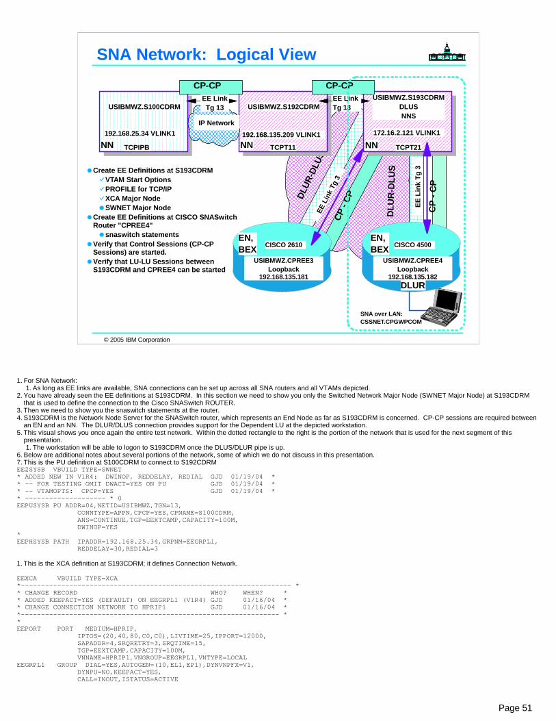
© 2005 IBM Corporation
SNA Network: Logical View
DLUR
-DLU
S
CP -
CP
CISCO 2610
USIBMWZ.CPREE3Loopback
192.168.135.181
EN,BEX
SNA over LAN:CSSNET.CPGWPCOM
CP
- CP
CISCO 4500
USIBMWZ.CPREE4Loopback
192.168.135.182
EN,BEX
DLUR
USIBMWZ.S193CDRMDLUSNNS
NN TCPT21
172.16.2.121 VLINK1
EE L
ink
Tg 3
USIBMWZ.S100CDRM
192.168.135.209 VLINK1
USIBMWZ.S192CDRM
NN NN
IP Network192.168.25.34 VLINK1
TCPIPB TCPT11
CP-CP CP-CPEE LinkTg 13
EE LinkTg 13
EE L
ink
Tg 3
DLU
R-D
LUSCreate EE Definitions at S193CDRM
VTAM Start OptionsPROFILE for TCP/IPXCA Major NodeSWNET Major Node
Create EE Definitions at CISCO SNASwitch Router "CPREE4"
snaswitch statementsVerify that Control Sessions (CP-CP Sessions) are started. Verify that LU-LU Sessions between S193CDRM and CPREE4 can be started
Page 51
1. For SNA Network:1. As long as EE links are available, SNA connections can be set up across all SNA routers and all VTAMs depicted.
2. You have already seen the EE definitions at S193CDRM. In this section we need to show you only the Switched Network Major Node (SWNET Major Node) at S193CDRM that is used to define the connection to the Cisco SNASwitch ROUTER.
3. Then we need to show you the snaswitch statements at the router. 4. S193CDRM is the Network Node Server for the SNASwitch router, which represents an End Node as far as S193CDRM is concerned. CP-CP sessions are required between
an EN and an NN. The DLUR/DLUS connection provides support for the Dependent LU at the depicted workstation.5. This visual shows you once again the entire test network. Within the dotted rectangle to the right is the portion of the network that is used for the next segment of this
presentation.1. The workstation will be able to logon to S193CDRM once the DLUS/DLUR pipe is up.
6. Below are additional notes about several portions of the network, some of which we do not discuss in this presentation.7. This is the PU definition at S100CDRM to connect to S192CDRMEE2SYSB VBUILD TYPE=SWNET * ADDED NEW IN V1R4: DWINOP, REDDELAY, REDIAL GJD 01/19/04 * * -- FOR TESTING OMIT DWACT=YES ON PU GJD 01/19/04 * * -- VTAMOPTS: CPCP=YES GJD 01/19/04 * * -------------------- * 0EEPUSYSB PU ADDR=04,NETID=USIBMWZ,TGN=13, CONNTYPE=APPN,CPCP=YES,CPNAME=S100CDRM, ANS=CONTINUE,TGP=EEXTCAMP,CAPACITY=100M, DWINOP=YES * EEPHSYSB PATH IPADDR=192.168.25.34,GRPNM=EEGRPL1, REDDELAY=30,REDIAL=3
1. This is the XCA definition at S193CDRM; it defines Connection Network.
EEXCA VBUILD TYPE=XCA *------------------------------------------------------------------- * * CHANGE RECORD WHO? WHEN? * * ADDED KEEPACT=YES (DEFAULT) ON EEGRPL1 (V1R4) GJD 01/16/04 * * CHANGE CONNECTION NETWORK TO HPRIP1 GJD 01/16/04 * *---------------------------------------------------------------- * * EEPORT PORT MEDIUM=HPRIP, IPTOS=(20,40,80,C0,C0),LIVTIME=25,IPPORT=12000, SAPADDR=4,SRQRETRY=3,SRQTIME=15, TGP=EEXTCAMP,CAPACITY=100M, VNNAME=HPRIP1,VNGROUP=EEGRPL1,VNTYPE=LOCAL EEGRPL1 GROUP DIAL=YES,AUTOGEN=(10,EL1,EP1),DYNVNPFX=V1, DYNPU=NO,KEEPACT=YES, CALL=INOUT,ISTATUS=ACTIVE

© 2005 IBM Corporation
DLU
R-D
LUS
CP
- CP
CISCO 4500
USIBMWZ.CPREE4Loopback
192.168.135.182
EN,BEX
DLUR
USIBMWZ.S193CDRMDLUSNNS
NN TCPT21
172.16.2.121 VLINK1
EE L
ink
Tg 3
SNA over LAN:CSSNET.CPGWPCOM
SWNET Major Node from S193CDRM to CPREE4
EE006BMN VBUILD TYPE=SWNET * ------------------------------------------------------- * * SWNET MAJOR NODE TO CONNECT TO CISCO 4006B SNASW * * ------------------------------------------------------- * * EEPU006B PU ADDR=04,NETID=USIBMWZ,TGN=3, X CONNTYPE=APPN,CPCP=YES,CPNAME=CPREE4, X ANS=CONTINUE,TGP=EEXTWAN,CAPACITY=100M, X DWINOP=YES EEPH006B PATH IPADDR=192.168.135.182,GRPNM=EEGRPL1, X REDDELAY=30,REDIAL=3
Create EE Definitions at S193CDRMVTAM Start OptionsPROFILE for TCP/IPXCA Major NodeSWNET Major Node
Create EE Definitions at CISCO SNASwitch Router "CPREE4"
snaswitch statementsVerify that Control Sessions (CP-CP Sessions) are started. Verify that LU-LU Sessions between S193CDRM and CPREE4 can be started
Step 2: Identify opposite EE Endpoint
TGN = optional
optional: SNASwitch dials in
Page 52
1. Specifying a TG number is completely optional. It is done here because some shops like to filter on TG number for network management purposes. They also use different APPN TG numbers in order to distinguish among different types o links.
2. The Branch Extender Node that CISCO represents knows only about the local topology from the upstream viewpoint because it looks like an End Node from that perspective. If there were an APPN network below the BEX node, the network topology would be known from the downstream perspective. In this case, there is no downstream APPN network because the SNASWitch node here is being used only to support dependent LU sessions.
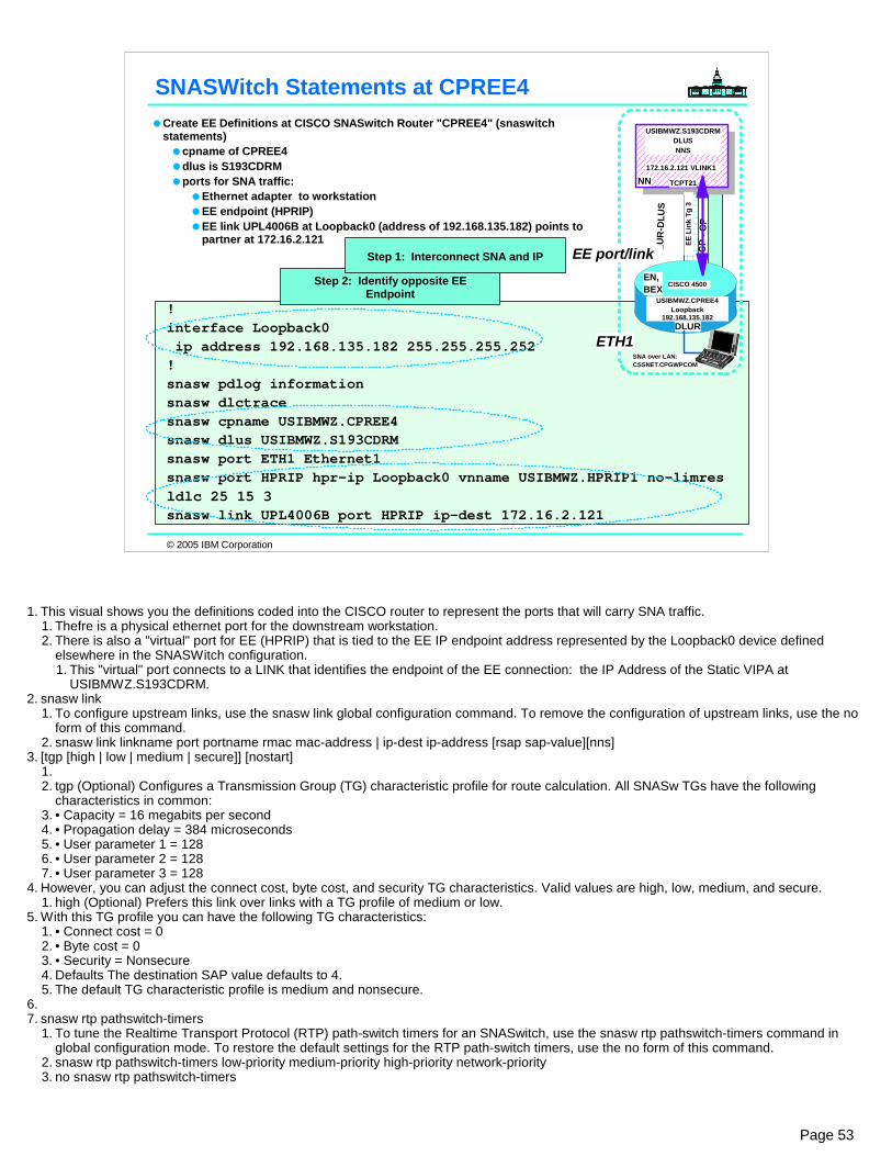
© 2005 IBM Corporation
! interface Loopback0 ip address 192.168.135.182 255.255.255.252 ! snasw pdlog informationsnasw dlctracesnasw cpname USIBMWZ.CPREE4snasw dlus USIBMWZ.S193CDRMsnasw port ETH1 Ethernet1snasw port HPRIP hpr-ip Loopback0 vnname USIBMWZ.HPRIP1 no-limres ldlc 25 15 3snasw link UPL4006B port HPRIP ip-dest 172.16.2.121
DLU
R-D
LUS
CP
- CP
CISCO 4500
USIBMWZ.CPREE4Loopback
192.168.135.182
EN,BEX
DLUR
USIBMWZ.S193CDRMDLUSNNS
NN TCPT21
172.16.2.121 VLINK1
EE L
ink
Tg 3
SNA over LAN:CSSNET.CPGWPCOM
SNASWitch Statements at CPREE4Create EE Definitions at CISCO SNASwitch Router "CPREE4" (snaswitch statements)
cpname of CPREE4dlus is S193CDRMports for SNA traffic:
Ethernet adapter to workstationEE endpoint (HPRIP)EE link UPL4006B at Loopback0 (address of 192.168.135.182) points to partner at 172.16.2.121
ETH1
EE port/link
Step 2: Identify opposite EE Endpoint
Step 1: Interconnect SNA and IP
Page 53
1. This visual shows you the definitions coded into the CISCO router to represent the ports that will carry SNA traffic.1. Thefre is a physical ethernet port for the downstream workstation.2. There is also a "virtual" port for EE (HPRIP) that is tied to the EE IP endpoint address represented by the Loopback0 device defined
elsewhere in the SNASWitch configuration.1. This "virtual" port connects to a LINK that identifies the endpoint of the EE connection: the IP Address of the Static VIPA at
USIBMWZ.S193CDRM.2. snasw link
1. To configure upstream links, use the snasw link global configuration command. To remove the configuration of upstream links, use the no form of this command.
2. snasw link linkname port portname rmac mac-address | ip-dest ip-address [rsap sap-value][nns]3. [tgp [high | low | medium | secure]] [nostart]
1.2. tgp (Optional) Configures a Transmission Group (TG) characteristic profile for route calculation. All SNASw TGs have the following
characteristics in common:3. • Capacity = 16 megabits per second4. • Propagation delay = 384 microseconds5. • User parameter 1 = 1286. • User parameter 2 = 1287. • User parameter 3 = 128
4. However, you can adjust the connect cost, byte cost, and security TG characteristics. Valid values are high, low, medium, and secure.1. high (Optional) Prefers this link over links with a TG profile of medium or low.
5. With this TG profile you can have the following TG characteristics:1. • Connect cost = 02. • Byte cost = 03. • Security = Nonsecure4. Defaults The destination SAP value defaults to 4.5. The default TG characteristic profile is medium and nonsecure.
6.7. snasw rtp pathswitch-timers
1. To tune the Realtime Transport Protocol (RTP) path-switch timers for an SNASwitch, use the snasw rtp pathswitch-timers command in global configuration mode. To restore the default settings for the RTP path-switch timers, use the no form of this command.
2. snasw rtp pathswitch-timers low-priority medium-priority high-priority network-priority3. no snasw rtp pathswitch-timers
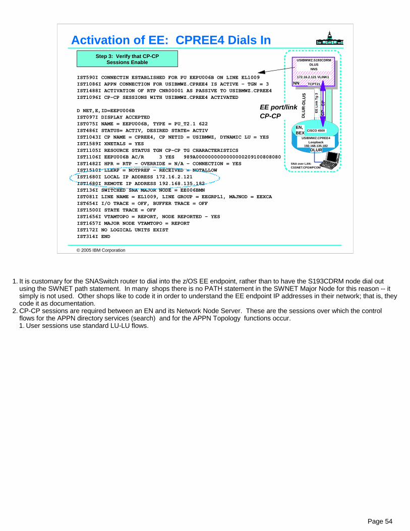
© 2005 IBM Corporation
Activation of EE: CPREE4 Dials In
IST590I CONNECTIN ESTABLISHED FOR PU EEPU006B ON LINE EL1009 IST1086I APPN CONNECTION FOR USIBMWZ.CPREE4 IS ACTIVE - TGN = 3 IST1488I ACTIVATION OF RTP CNR00001 AS PASSIVE TO USIBMWZ.CPREE4 IST1096I CP-CP SESSIONS WITH USIBMWZ.CPREE4 ACTIVATED
D NET,E,ID=EEPU006B IST097I DISPLAY ACCEPTED IST075I NAME = EEPU006B, TYPE = PU_T2.1 622 IST486I STATUS= ACTIV, DESIRED STATE= ACTIV IST1043I CP NAME = CPREE4, CP NETID = USIBMWZ, DYNAMIC LU = YES IST1589I XNETALS = YES IST1105I RESOURCE STATUS TGN CP-CP TG CHARACTERISTICS IST1106I EEPU006B AC/R 3 YES 989A0000000000000000209100808080 IST1482I HPR = RTP - OVERRIDE = N/A - CONNECTION = YES IST1510I LLERP = NOTPREF - RECEIVED = NOTALLOW IST1680I LOCAL IP ADDRESS 172.16.2.121 IST1680I REMOTE IP ADDRESS 192.168.135.182 IST136I SWITCHED SNA MAJOR NODE = EE006BMN IST081I LINE NAME = EL1009, LINE GROUP = EEGRPL1, MAJNOD = EEXCA IST654I I/O TRACE = OFF, BUFFER TRACE = OFF IST1500I STATE TRACE = OFF IST1656I VTAMTOPO = REPORT, NODE REPORTED - YES IST1657I MAJOR NODE VTAMTOPO = REPORT IST172I NO LOGICAL UNITS EXIST IST314I END
DLU
R-D
LUS
CP
- CP
CISCO 4500
USIBMWZ.CPREE4Loopback
192.168.135.182
EN,BEX
DLUR
USIBMWZ.S193CDRMDLUSNNS
NN TCPT21
172.16.2.121 VLINK1
EE L
ink
Tg 3
SNA over LAN:CSSNET.CPGWPCOM
EE port/linkCP-CP
Step 3: Verify that CP-CP Sessions Enable
Page 54
1. It is customary for the SNASwitch router to dial into the z/OS EE endpoint, rather than to have the S193CDRM node dial out using the SWNET path statement. In many shops there is no PATH statement in the SWNET Major Node for this reason -- it simply is not used. Other shops like to code it in order to understand the EE endpoint IP addresses in their network; that is, they code it as documentation.
2. CP-CP sessions are required between an EN and its Network Node Server. These are the sessions over which the control flows for the APPN directory services (search) and for the APPN Topology functions occur.1. User sessions use standard LU-LU flows.
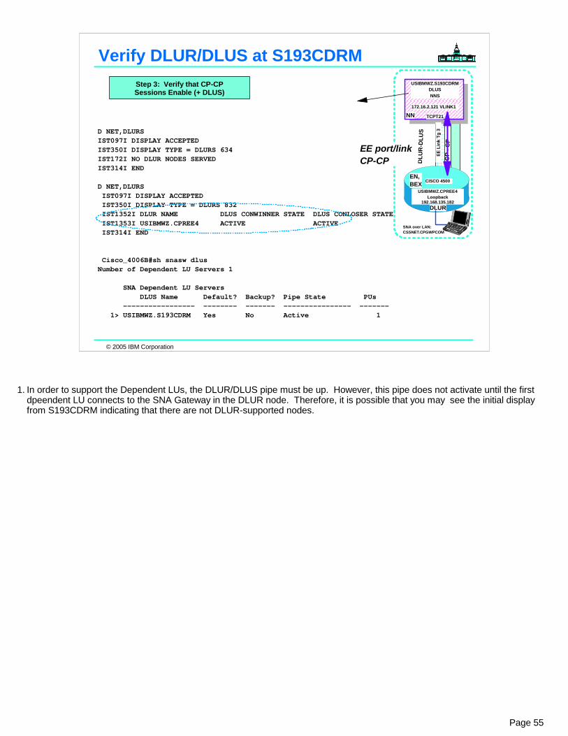
© 2005 IBM Corporation
Verify DLUR/DLUS at S193CDRM
D NET,DLURS IST097I DISPLAY ACCEPTED IST350I DISPLAY TYPE = DLURS 634 IST172I NO DLUR NODES SERVED IST314I END
D NET,DLURS IST097I DISPLAY ACCEPTED IST350I DISPLAY TYPE = DLURS 832 IST1352I DLUR NAME DLUS CONWINNER STATE DLUS CONLOSER STATE IST1353I USIBMWZ.CPREE4 ACTIVE ACTIVE IST314I END
Cisco_4006B#sh snasw dlus Number of Dependent LU Servers 1 SNA Dependent LU Servers DLUS Name Default? Backup? Pipe State PUs ----------------- -------- ------- ---------------- ------- 1> USIBMWZ.S193CDRM Yes No Active 1
DLU
R-D
LUS
CP
- CP
CISCO 4500
USIBMWZ.CPREE4Loopback
192.168.135.182
EN,BEX
DLUR
USIBMWZ.S193CDRMDLUSNNS
NN TCPT21
172.16.2.121 VLINK1
EE L
ink
Tg 3
SNA over LAN:CSSNET.CPGWPCOM
EE port/linkCP-CP
Step 3: Verify that CP-CP Sessions Enable (+ DLUS)
Page 55
1. In order to support the Dependent LUs, the DLUR/DLUS pipe must be up. However, this pipe does not activate until the first dpeendent LU connects to the SNA Gateway in the DLUR node. Therefore, it is possible that you may see the initial display from S193CDRM indicating that there are not DLUR-supported nodes.
© 2005 IBM Corporation
Appendix:EE Connection Network for z/OS
and SNASwitch Router
Page 56

© 2005 IBM Corporation
Connection Network: Logical View
SNA over LAN:CSSNET.CPGWPCOM
IP Network
CISCO 4500
USIBMWZ.CPREE4Loopback
192.168.135.182
EN,BEX
DLUR
Connection NetworkHPRIP1
192.168.25.34 VLINK1
USIBMWZ.S100CDRM
NN
IP Network
TCPIPB
192.168.135.209 VLINK1
USIBMWZ.S192CDRMUSIBMWZ.S193CDRM
DLUSNNS
NN NNTCPT11 TCPT21
172.16.2.121 VLINK1
CP-CP CP-CPEE LinkTg 13
EE LinkTg 13
Tg 21 Tg 21
Tg 1
Tg 1
CISCO 2610
USIBMWZ.CPREE3Loopback
192.168.135.181
EN,BEX
Tg 1
Create EE Definitions at S193CDRMVTAM Start OptionsPROFILE for TCP/IPXCA Major NodeSWNET Major NodeCreate XCA Major Node for Connection Network
Create EE Definitions at CISCO SNASwitch Router "CPREE4"
snaswitch statementsCreate Connection Network definition in snaswitch statements
Verify that Control Sessions (CP-CP Sessions) are started. Verify that LU-LU Sessions between S193CDRM and CPREE4 can be started
Page 57
1. We want to set up Connection Network definitions so that direct routing can take place for LU-LU sessions. We will show you the definitions in S192CDRM, S193CDRM,and in CPREE4. Each of these should become a member of the same connection network. 1. The existence of the Connection network allows a direct connection between CPREE4 and S192CDRM without passing
through the S192CDRM system, to which CPREE4 has a predefined link.1. VRN links may be used only for LU-LU sesions and not for CP-CP sessions.
2. It is not possible to designate a separate TG number for Connection Network. Cisco uses TG1 on its end; z/OS uses TG 21 (or similar) on its end.
3. There are both LOCAL and GLOBAL Connection networks (or Local VRNs and Global VRNs). In this brief topic we focus only on LVRNs. We do not focus on the coding that allows you to place the VRN name on the Group statement (introduced at V1R2). Neither do we focus on the V1R4 enhancements, that permitted placing Transmission Group Profile characteristics on the GROUP statement instead of on the PORT. We also do not address the enhancements for multiple VRNS that were introduced in z/OS V1R6.
2. We focus on the portion of the network within the dotted lines.3. Important NOTES follow:4. Connection network names are specified as fully qualified, in the form NETID.vnname (meaning virtual node name). All nodes
on the same shared media which also have connection network functions can specify the SAME NETID.vnname which allows the node computing the route to recognize that they are on the same shared media and are capable of bringing up dynamic links for LU-LU sessions.1. Connection network links are NOT used for CP-CP sessions.
5. ENs need to predefine a link to their network node server (and usually to their backup network node server) and may predefine links to other nodes, as well. The predefined link to the network node server is used for CP-CP sessions. 1. Connection network links are used only for LU-LU sessions and normally are brought down when the session(s) ends.
6. NNs normally predefine links and allow CP-CP sessions on all these links to every adjacent network node. As with ENs, connection network links can be used for LU-LU sessions between these NNs and other nodes which define the SAME connection network name.
7. Connection network names and links show up on displays. The connection network itself looks like an adjacent NN which doesn't allow CP-CP sessions on links to it.
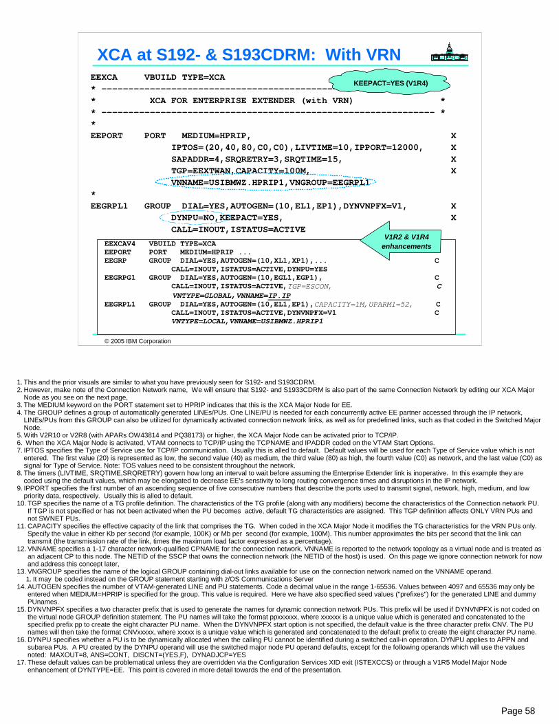
© 2005 IBM Corporation
EEXCA VBUILD TYPE=XCA * -------------------------------------------------------------- * * XCA FOR ENTERPRISE EXTENDER (with VRN) * * -------------------------------------------------------------- * * EEPORT PORT MEDIUM=HPRIP, X IPTOS=(20,40,80,C0,C0),LIVTIME=10,IPPORT=12000, X SAPADDR=4,SRQRETRY=3,SRQTIME=15, X TGP=EEXTWAN,CAPACITY=100M, X VNNAME=USIBMWZ.HPRIP1,VNGROUP=EEGRPL1 * EEGRPL1 GROUP DIAL=YES,AUTOGEN=(10,EL1,EP1),DYNVNPFX=V1, X DYNPU=NO,KEEPACT=YES, X CALL=INOUT,ISTATUS=ACTIVE
XCA at S192- & S193CDRM: With VRNKEEPACT=YES (V1R4)
EEXCAV4 VBUILD TYPE=XCA EEPORT PORT MEDIUM=HPRIP ... EEGRP GROUP DIAL=YES,AUTOGEN=(10,XL1,XP1),... C CALL=INOUT,ISTATUS=ACTIVE,DYNPU=YES EEGRPG1 GROUP DIAL=YES,AUTOGEN=(10,EGL1,EGP1), C CALL=INOUT,ISTATUS=ACTIVE,TGP=ESCON, C VNTYPE=GLOBAL,VNNAME=IP.IP EEGRPL1 GROUP DIAL=YES,AUTOGEN=(10,EL1,EP1),CAPACITY=1M,UPARM1=52, C CALL=INOUT,ISTATUS=ACTIVE,DYNVNPFX=V1 C VNTYPE=LOCAL,VNNAME=USIBMWZ.HPRIP1
V1R2 & V1R4enhancements
Page 58
1. This and the prior visuals are similar to what you have previously seen for S192- and S193CDRM.2. However, make note of the Connection Network name, We will ensure that S192- and S1933CDRM is also part of the same Connection Network by editing our XCA Major
Node as you see on the next page, 3. The MEDIUM keyword on the PORT statement set to HPRIP indicates that this is the XCA Major Node for EE.4. The GROUP defines a group of automatically generated LINEs/PUs. One LINE/PU is needed for each concurrently active EE partner accessed through the IP network,
LINEs/PUs from this GROUP can also be utilized for dynamically activated connection network links, as well as for predefined links, such as that coded in the Switched Major Node.
5. With V2R10 or V2R8 (with APARs OW43814 and PQ38173) or higher, the XCA Major Node can be activated prior to TCP/IP. 6. When the XCA Major Node is activated, VTAM connects to TCP/IP using the TCPNAME and IPADDR coded on the VTAM Start Options.7. IPTOS specifies the Type of Service use for TCP/IP communication. Usually this is alled to default. Default values will be used for each Type of Service value which is not
entered. The first value (20) is represented as low, the second value (40) as medium, the third value (80) as high, the fourth value (C0) as network, and the last value (C0) as signal for Type of Service. Note: TOS values need to be consistent throughout the network.
8. The timers (LIVTIME, SRQTIME,SRQRETRY) govern how long an interval to wait before assuming the Enterprise Extender link is inoperative. In this example they are coded using the default values, which may be elongated to decrease EE's senstivity to long routing convergence times and disruptions in the IP network.
9. IPPORT specifies the first number of an ascending sequence of five consecutive numbers that describe the ports used to transmit signal, network, high, medium, and low priority data, respectively. Usually this is alled to default.
10. TGP specifies the name of a TG profile definition. The characteristics of the TG profile (along with any modifiers) become the characteristics of the Connection network PU. If TGP is not specified or has not been activated when the PU becomes active, default TG characteristics are assigned. This TGP definition affects ONLY VRN PUs and not SWNET PUs.
11. CAPACITY specifies the effective capacity of the link that comprises the TG. When coded in the XCA Major Node it modifies the TG characteristics for the VRN PUs only. Specify the value in either Kb per second (for example, 100K) or Mb per second (for example, 100M). This number approximates the bits per second that the link can transmit (the transmission rate of the link, times the maximum load factor expressed as a percentage).
12. VNNAME specifies a 1-17 character network-qualified CPNAME for the connection network. VNNAME is reported to the network topology as a virtual node and is treated as an adjacent CP to this node. The NETID of the SSCP that owns the connection network (the NETID of the host) is used. On this page we ignore connection network for now and address this concept later,
13. VNGROUP specifies the name of the logical GROUP containing dial-out links available for use on the connection network named on the VNNAME operand.1. It may be coded instead on the GROUP statement starting with z/OS Communications Server
14. AUTOGEN specifies the number of VTAM-generated LINE and PU statements. Code a decimal value in the range 1-65536. Values between 4097 and 65536 may only be entered when MEDIUM=HPRIP is specified for the group. This value is required. Here we have also specified seed values ("prefixes") for the generated LINE and dummy PUnames.
15. DYNVNPFX specifies a two character prefix that is used to generate the names for dynamic connection network PUs. This prefix will be used if DYNVNPFX is not coded on the virtual node GROUP definition statement. The PU names will take the format ppxxxxxx, where xxxxxx is a unique value which is generated and concatenated to the specified prefix pp to create the eight character PU name. When the DYNVNPFX start option is not specified, the default value is the three character prefix CNV. The PU names will then take the format CNVxxxxx, where xxxxx is a unique value which is generated and concatenated to the default prefix to create the eight character PU name.
16. DYNPU specifies whether a PU is to be dynamically allocated when the calling PU cannot be identified during a switched call-in operation. DYNPU applies to APPN and subarea PUs. A PU created by the DYNPU operand will use the switched major node PU operand defaults, except for the following operands which will use the values noted: MAXOUT=8, ANS=CONT, DISCNT=(YES,F), DYNADJCP=YES
17. These default values can be problematical unless they are overridden via the Configuration Services XID exit (ISTEXCCS) or through a V1R5 Model Major Node enhancement of DYNTYPE=EE. This point is covered in more detail towards the end of the presentation.
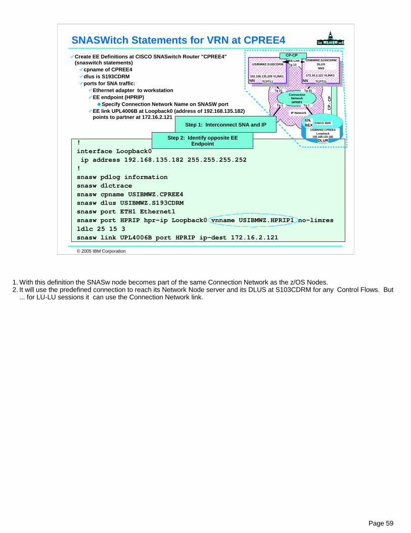
© 2005 IBM Corporation
! interface Loopback0 ip address 192.168.135.182 255.255.255.252 ! snasw pdlog informationsnasw dlctracesnasw cpname USIBMWZ.CPREE4snasw dlus USIBMWZ.S193CDRMsnasw port ETH1 Ethernet1snasw port HPRIP hpr-ip Loopback0 vnname USIBMWZ.HPRIP1 no-limres ldlc 25 15 3snasw link UPL4006B port HPRIP ip-dest 172.16.2.121
SNASWitch Statements for VRN at CPREE4Create EE Definitions at CISCO SNASwitch Router "CPREE4" (snaswitch statements)
cpname of CPREE4dlus is S193CDRMports for SNA traffic:
Ethernet adapter to workstationEE endpoint (HPRIP)
Specify Connection Network Name on SNASW portEE link UPL4006B at Loopback0 (address of 192.168.135.182) points to partner at 172.16.2.121
CP
- CP
IP Network
CISCO 4500
USIBMWZ.CPREE4Loopback
192.168.135.182
EN,BEX
DLUR
Connection NetworkHPRIP1
192.168.135.209 VLINK1
USIBMWZ.S192CDRMUSIBMWZ.S193CDRM
DLUSNNS
NN NNTCPT11 TCPT21
172.16.2.121 VLINK1
CP-CPEE LinkTg 13
Tg 21 Tg 21
Tg 1Tg 1
Step 2: Identify opposite EE Endpoint
Step 1: Interconnect SNA and IP
Page 59
1. With this definition the SNASw node becomes part of the same Connection Network as the z/OS Nodes.2. It will use the predefined connection to reach its Network Node server and its DLUS at S103CDRM for any Control Flows. But
... for LU-LU sessions it can use the Connection Network link.

© 2005 IBM Corporation
V NET,ACT,ID=EEXCA IST097I VARY ACCEPTED IST093I EEXCA ACTIVE EZZ4324I CONNECTION TO 172.16.2.121 ACTIVE FOR DEVICE IUTSAMEH IST1685I TCP/IP JOB NAME = TCPT21 IST1680I LOCAL IP ADDRESS 172.16.2.121 IST1168I VIRTUAL NODE USIBMWZ.HPRIP1 CONNECTION ACTIVE D NET,E,ID=EEXCA IST097I DISPLAY ACCEPTED IST075I NAME = EEXCA, TYPE = XCA MAJOR NODE 930 IST486I STATUS= ACTIV, DESIRED STATE= ACTIV IST1679I MEDIUM = HPRIP IST1685I TCP/IP JOB NAME = TCPT21 IST1680I LOCAL IP ADDRESS 172.16.2.121 IST1324I VNNAME = USIBMWZ.HPRIP1 VNGROUP = EEGRPL1 (LOCAL) IST1105I RESOURCE STATUS TGN CP-CP TG CHARACTERISTICS IST1106I EEXCA AC/R 21 NO 909A0000000000000000209100808080 IST654I I/O TRACE = OFF, BUFFER TRACE = OFF IST1656I VTAMTOPO = REPORT, NODE REPORTED - YES IST170I LINES: IST232I EL1000 ACTIV IST232I EL1001 ACTIV IST232I EL1002 ACTIV IST232I EL1003 ACTIV IST232I EL1004 ACTIV IST232I EL1005 ACTIV IST232I EL1006 ACTIV IST232I EL1007 ACTIV IST232I EL1008 ACTIV IST232I EL1009 ACTIV IST314I END
Activation at S193CDRM of XCA & VRN
Generated with "EL1" prefix.
V1R4 Display
Page 60
1. The display at S192CDRM would be similar, but it would, of course, display the EE endpoint address and the TCPIP procedure name at that node.
2. Note how the activation of the VRN is indicated in the displays.3. Also note how the XCA Major Node autogens the lines with the prefix identified in the definition on the previous page.
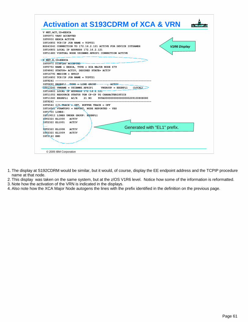
© 2005 IBM Corporation
V NET,ACT,ID=EEXCA IST097I VARY ACCEPTED IST093I EEXCA ACTIVE IST1685I TCP/IP JOB NAME = TCPT21 EZZ4324I CONNECTION TO 172.16.2.121 ACTIVE FOR DEVICE IUTSAMEH IST1680I LOCAL IP ADDRESS 172.16.2.121 IST1168I VIRTUAL NODE USIBMWZ.HPRIP1 CONNECTION ACTIVE ...D NET,E,ID=EEXCA IST097I DISPLAY ACCEPTED IST075I NAME = EEXCA, TYPE = XCA MAJOR NODE 679 IST486I STATUS= ACTIV, DESIRED STATE= ACTIV IST1679I MEDIUM = HPRIP IST1685I TCP/IP JOB NAME = TCPT21 IST924I ------------------------------------------------------------- IST089I EEGRPL1 TYPE = LINE GROUP , ACTIV IST1324I VNNAME = USIBMWZ.HPRIP1 VNGROUP = EEGRPL1 (LOCAL) IST1680I LOCAL IP ADDRESS 172.16.2.121 IST1105I RESOURCE STATUS TGN CP-CP TG CHARACTERISTICS IST1106I EEGRPL1 AC/R 21 NO 909A0000000000000000209100808080 IST924I -------------------------------------------------------------IST654I I/O TRACE = OFF, BUFFER TRACE = OFF IST1656I VTAMTOPO = REPORT, NODE REPORTED - YES IST170I LINES: IST1901I LINES UNDER GROUP: EEGRPL1 IST232I EL1000 ACTIV IST232I EL1001 ACTIV ...IST232I EL1008 ACTIV IST232I EL1009 ACTIV IST314I END
Activation at S193CDRM of XCA & VRN
Generated with "EL1" prefix.
V1R6 Display
Page 61
1. The display at S192CDRM would be similar, but it would, of course, display the EE endpoint address and the TCPIP procedure name at that node.
2. This display was taken on the same system, but at the z/OS V1R6 level. Notice how some of the information is reformatted.3. Note how the activation of the VRN is indicated in the displays.4. Also note how the XCA Major Node autogens the lines with the prefix identified in the definition on the previous page.

© 2005 IBM Corporation
CP
- CP
IP Network
CISCO 4500
USIBMWZ.CPREE4Loopback
192.168.135.182
EN,BEX
DLUR
Connection NetworkHPRIP1
192.168.135.209 VLINK1
USIBMWZ.S192CDRMUSIBMWZ.S193CDRM
DLUSNNS
NN NNTCPT11 TCPT21
172.16.2.121 VLINK1
CP-CPEE LinkTg 13
Tg 21 Tg 21
Tg 1Tg 1
D NET,APING,ID=CPREE4 IST097I DISPLAY ACCEPTED IST1576I DYNAMIC SWITCHED MAJOR NODE ISTDSWMN CREATED IST590I CONNECTOUT ESTABLISHED FOR PU V1000002 ON LINE EL1001 IST1086I APPN CONNECTION FOR USIBMWZ.CPREE4 IS ACTIVE - TGN = 21 IST1488I ACTIVATION OF RTP CNR00003 AS ACTIVE TO USIBMWZ.CPREE4 IST1488I ACTIVATION OF RTP CNR00004 AS ACTIVE TO USIBMWZ.CPREE4 IST1488I ACTIVATION OF RTP CNR00005 AS ACTIVE TO USIBMWZ.CPREE4 IST1489I APING SESSION INFORMATION 590 IST1490I DLU=USIBMWZ.CPREE4 SID=D87F780ACE8852EE IST933I LOGMODE=#INTER , COS=*BLANK* IST875I APPNCOS TOWARDS SLU = #INTER IST1460I TGN CPNAME TG TYPE HPR IST1461I 21 USIBMWZ.HPRIP1 APPN RTP IST1461I 1 USIBMWZ.CPREE4 APPN RTP IST314I END IST1457I VTAM APING VERSION 2R33 (PARTNER TP VERSION 2R35) 591 IST1490I DLU=USIBMWZ.CPREE4 SID=D87F780ACE8852EE IST1462I ECHO IS ON IST1463I ALLOCATION DURATION: 116 MILLISECONDS IST1464I PROGRAM STARTUP AND VERSION EXCHANGE: 19 MILLISECONDS IST1465I DURATION DATA SENT DATA RATE DATA RATE IST1466I (MILLISECONDS) (BYTES) (KBYTE/SEC) (MBIT/SEC) IST1467I 20 200 10 0 IST1467I 21 200 9 0 IST1468I TOTALS: 41 400 9 0 IST1469I DURATION STATISTICS: IST1470I MINIMUM = 20 AVERAGE = 20 MAXIMUM = 21 IST314I END
APING Session: S192CDRM to CPREE4
Connection Network (VRN)
Through Connection Network
Step 3: All CP-CPs Up
Step 4: LU-LU Session Uses VRN
Page 62
1. We have established an LU-LU session from S192CDRM to CPREE4 with the APING command. The display shows the path taken: it uses VRN. 1. Note how the appropriate CP sessions needed to be up for this LU-LU path to be chosen:
1. CP-CP between CPREE4 and S193CDRM2. CP-CP begtween S193CDRM and S192CDRM
2. If you are having problems with data flowing through the network, whereby at times sessions are dropped, you may want to execute the APING command by specifying a packet size to determine if MTUsizes are hurting you in the network: 1. D NET,APING,ID=CPREE4,SIZE=1500.
© 2005 IBM Corporation
Appendix: Some V1R4 Enhancements to EE
Page 63
1. This is only a partial listing of V1R4 EE enhancements that affect the coding we have shown you in this brief presentation..2. There have also been many enhancements to EE management and performance, and configuration design in V1R5 and V1R6.
Please see other presentations and documents for details.

© 2005 IBM Corporation
New XCA LINE Operand:KEEPACT=YES|NO
Ability to place EE XCA major node in VTAM's configuration list. In the event of any failure (IP network, TCP/IP stack termination, problem in EE partner node, etc.), EE connections should automatically redrive.Pre-V1R4: If the TCP/IP stack is recycled, the EE XCA Major Node needs to be reactivated
New Switched PU Operand:DWINOP=YES|NO
With DWACT=YES specified on PUs, EE should activate automatically.Ability to place Switched Major Node in VTAM's configuration list. Pre-V1R4:
If switched PU dials occur before XCA lines are active or before the partner is ready, dials will fail (with no automatic redrive).If an EE connection inops, no automatic redial is attempted.
New PATH Operands in switched deck:REDIAL=0-254|FOREVER (Default of 3)REDDELAY=1-1200 (seconds) (Default of 30 secs)
V1R4 Dial Usability for EE
Page 64
1. Early EE users identified need for automatic activation and recovery of EE connectivity. z/OS V1R4 CS enhances the dial processing for Enterprise Extender connections to attempt automatic redial both in the case where an initial dial fails and in the case where an existing connection fails. Prior to z/OS V1R4 Communications Server, there was no mechanism to automatically attempt to redial a switched Physical Unit for Enterprise Extender when a dial attempt failed or when an existing connection INOPed.
2. Prior to V1R4:1. If switched PU dials occur before XCA lines are active or before the partner is ready, dials will fail (with no automatic redrive).2. If an EE connection inops, no automatic redial is attempted.3. If the TCP/IP stack is recycled, the EE XCA Major Node needs to be reactivated
3. V1R4 provides new XCA Parameter:1. KEEPACT=YES|NO2. In the event of any failure (IP network, TCP/IP stack termination, problem in EE partner node, etc.), EE connections should
automatically redrive.4. Prior to V1R4:
1. No automatic redial for a Switched PU for Enterprise Extender1. If initial dial fails2. If an existing connection fails
2. DWACT=YES may be coded in SWNET so that dial operation occurs when Major Node is first activated but no redial is attempted if that fails
5. V1R4 provides three new SWNET Parameters:1. DWINOP - to cause redials to happen if an existing link becomes inoperative2. REDIAL - to specify a number of redials to attempt if a dial operation fails3. REDDELAY - to specify a value to wait in between redial attempts

© 2005 IBM Corporation
Appendix: Some V1R5 and V1R6 Enhancements to EE
Page 65
1. This is only a partial listing of V1R4 EE enhancements that affect the coding we have shown you in this brief presentation..2. There have also been many enhancements to EE management and performance, and configuration design in V1R5 and V1R6.
Please see other presentations and documents for details.

© 2005 IBM Corporation
V1R5 & V1R6 Enhancements to EE (Summary)
V1R5Multiple Static VIPAs for EE connectionsNetwork Address Table (NAT) Compatibility for Connection Network
Hostname vs. IPaddr to connect via EE (IPv6, NAT, etc.)Message to indicate VRN dialout not availableModel PU for DYNTYPE=EE (when DYNPU=YES on XCA)Network Management API for Tivoli and OEM Products
V1R6Vary Activate,Update=ALL on XCA Major NodeD NET,EE Command for Network ManagementEE Connection Network Reachability AwarenessEnhancements for D NET,RTPs command outputExtended Border Node Session Awareness
Useful for Cross-Net Session Filtering (via DSME, for example) when an SME was previously used for SNI and equivalent function required in Enterprise Extender
Page 66
1. V1R5 increases EE flexibility with support for multiple VRNs, multiple VIPAs, IPv6, and NAT compatibility. With the flexibility comes additional complexity, and this often leads to the need to add or change definitions.1. However, currently those definitions cannot be changed or augmented once the XCA major node is active, without inactivating
the major node, thereby disrupting all existing Enterprise Extender connections.2. V1R6 improves usability by allowing the UPDATE operand on the VARY command for the EE XCA major node, thereby allowing
adding of GROUPs and changing of operand values, without bouncing the major node.1. However, note that a GROUP must itself be inactive before its operands can be changed. To simplify the inactivation of a
GROUP prior to a change (or activation after a change), V1R6 also allows a VARY ACT (or VARY INACT) command to be issued against an EE XCA GROUP, thereby activating (or inactivating) the GROUP and all subordinate LINEs/PUs.

© 2005 IBM Corporation
Appendix:Planning for EE
Page 67

© 2005 IBM Corporation
Avoiding Gotcha's in Planning for EE
Plan properly for an APPN/HPR implementation in at least one Subarea Node
IBM Training and Education Services Course G3945 "VTAM/APPN Concepts and Implementation" - or - obtain equivalent experienceAssign appropriate TG weights for the APPN Enterprise Extender connections
ARB Mechanism, Route Selection (Topology & Routing Services - TRS)Larger MTUs tend to yield better performance.
Use ENHADDR=YES at VTAMWork with MVS, VTAM, and TCP/IP capacity planning personnel
Monitor for changed traffic patterns and resource utilization within the subsystems and across different channel subsystems
Work with IP Router Networking Infrastructure groups Monitor Router Queue lengths and buffersEnsure that IP TOS is being honored in router network.
Don't attempt to implement EE Connection Network across a NAT'd IP network until V1R5
Standard EE across a NAT'd network is fine
Page 68
1. Plan properly for an APPN/HPR implementation in at least one Subarea Node1. Attend IBM Training and Education Services Course G3945 "VTAM/APPN Concepts and Implementation" - or - obtain equivalent experience2. Ensure that the TG weights for the APPN Enterprise Extender connections are appropriate in both directions (at both endpoints) so that
Adaptive Rate-Based Congestion control works and so that APPN route selection occurs as expected.1. NN-NN Links must be same for correct Route Selection from each direction; EN view of TG characteristics is used for NN-EN Route
Selection.3. Avoid segmentation of SNA and Network Layer Packets (NLPs) by setting the IP MTUsize larger than 768
1. Don't use IP defaults for MTU at IP or in OMPROUTE (Path MTU Discovery is not used for EE)2. To ensure optimal performance, the TCP/IP maximum transmission unit (MTU) size should be greater than or equal to the RTP Network
Layer Packet (NLP) size. VTAM will query TCP/IP for its MTU size when establishing an RTP connection (for a CP-CP session, to transport ROUTE_SETUP GDS variables, or for an LU-LU session). If the connection is within the node starting the RTP connection, VTAM sets the maximum packet size equal to the lesser of the MTU size or the VTAM maximum data size. If the connection is within an intermediate node or destination node, VTAM sets the maximum packet size equal to the lesser of the MTU size, VTAM maxiumum data size for the next hop, or the value received on the ROUTE_SETUP GDS variable.
3. Note: If the MTU size is below 768 bytes, VTAM sets the maximum packet size to 768 (this is the smallest maximum packet size allowed by VTAM). This limitation can cause TCP/IP to fragment if the MTU size is set below 768 bytes, but exists because the RTP layer can not allow the HPR header to be segmented in the RTP layer.
2. If not already doing so, start using VTAM Start Option of ENHADDR=YES.1. If you specify ENHADDR=NO all element addresses that VTAM obtains for resources in this subarea come out of the 64k element pool. This
includes each active (connectable) APPL (two if PARSESS=YES), each activated local LU and PU, each dynamically defined LU and PU (once connected). We must also obtain a session partner element address for each session in which we are the endpoint or intermediate routing point (unless the session path to that partner is over a FID_4 link - because, in this case, the element address will originate from another subarea's address space). APPN session partner element addresses come out of this subarea's 64K element address pool if you specify ENHADDR=NO. Finally, every SSCP_LU and SSCP_PU element address for DLUR/DLUS comes out of this 64K element address pool.
2. ENHADDR=YES Specifies that you can use high-order element addresses for application programs.3. Work with IP Router Networking Infrastructure groups to monitor for increased traffic across the router network
1. Router Queue lengths and buffers2. Ensure that IP TOS is being honored in router network.
4. Work with MVS, VTAM, and TCP/IP capacity planning personnel at your site to monitor for changed traffic patterns within the subsystems and across different channel subsystems
5. Don't attempt to implement EE Connection Network across a NAT'd IP network until V1R51. Standard EE across a NAT'd network is fine
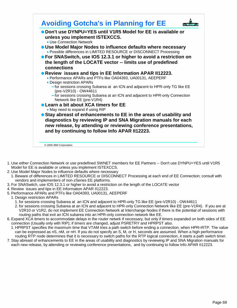
© 2005 IBM Corporation
Avoiding Gotcha's in Planning for EEDon't use DYNPU=YES until V1R5 Model for EE is available or unless you implement ISTEXCCS.
Use Connection NetworkUse Model Major Nodes to influence defaults where necessary
Possible differences in LIMITED RESOURCE or DISCONNECT Processing For SNASwitch, use IOS 12.3.1 or higher to avoid a restriction on the length of the LOCATE vector -- limits use of predefined connectionsReview issues and tips in EE Information APAR II12223.
Performance APARs and PTFs like OA04393, UA00131, AEEPERF Design restriction APARs
for sessions crossing Subarea at an ICN and adjacent to HPR-only TG like EE (pre-V2R10) - OW44611for sessions crossing Subarea at an ICN and adjacent to HPR-only Connection Network like EE (pre-V1R4)
Learn a bit about XCA timers for EEMay need to expand if using RIP
Stay abreast of enhancements to EE in the areas of usability and diagnostics by reviewing IP and SNA Migration manuals for each new release, by attending or reviewing conference presentations, and by continuing to follow Info APAR II12223.
Page 69
1. Use either Connection Network or use predefined SWNET members for EE Partners -- Don't use DYNPU=YES until V1R5 Model for EE is available or unless you implement ISTEXCCS.
2. Use Model Major Nodes to influence defaults where necessary1. Beware of differences in LIMITED RESOURCE or DISCONNECT Processing at each end of EE Connection; consult with
vendors and implementers of non-zSeries EE platforms.3. For SNASwitch, use IOS 12.3.1 or higher to avoid a restriction on the length of the LOCATE vector4. Review issues and tips in EE Information APAR II12223.5. Performance APARs and PTFs like OA04393, UA00131, AEEPERF
1. Design restriction APARs 1. for sessions crossing Subarea at an ICN and adjacent to HPR-only TG like EE (pre-V2R10) - OW44611 2. for sessions crossing Subarea at an ICN and adjacent to HPR-only Connection Network like EE (pre-V1R4). If you are at
V2R10 or V1R2, do not implement EE Connection Network at Interchange Nodes if there is the potential of sessions with routing paths that exit an ICN subarea into an HPR-only connection network like EE.
6. Expand XCA timers to accommodate delays in the router netwrk if necessary, but only if timers expanded on both sides of EE connection (Usually only with RIP); if timers are changed, adjust PSRETRY and HPRPST also.1. HPRPST specifies the maximum time that VTAM tries a path switch before ending a connection, when HPR=RTP. The value
can be expressed as nS, nM, or nH. If you do not specify an S, M, or H, seconds are assumed. When a high performance routing RTP node determines that it is necessary to switch paths for the RTP logical connection, it starts a path switch timer.
7. Stay abreast of enhancements to EE in the areas of usability and diagnostics by reviewing IP and SNA Migration manuals for each new release, by attending or reviewing conference presentations, and by continuing to follow Info APAR II12223.

© 2005 IBM Corporation
New Ways to Manipulate Some Switched Values
Code Model Major Node for ...DYNTPE=RTPDYNTYPE=VN DYNTYPE=XCF
DYNTYPE=EE (V1R5 only: for EE PUs otherwise generated with DYNPU=YES)
Doesn't require Switched Connection Exit (ISTEXCCS) to apply definitions in Model as was always the case prior to this enhancement.
APAR OW57263/UW96454 to enable coding of CPCP=YES for RTP Pipe.
MODRTP VBUILD TYPE=MODEL RTPPU PU DYNTYPE=RTP,DISCNT=(DELAY,,60) <<<or>>> DISCNT=NO
MODVN VBUILD TYPE=MODEL VNPU PU DISCNT=(DELAY,,60),DYNTYPE=VN <<<or>>> DISCNT=NO
MODXCF VBUILD TYPE=MODEL XCFT* PU TRLE=XCFP*,CAPACITY=160M,DYNTYPE=XCF <<<or>>> DISCNT=NO
MODEE VBUILD TYPE=MODEL EEMODEL PU DYNTYPE=EE,CAPACITY=100M,DISCNT=NO,DWINOP=YES,
REDIAL=30,REDDELAY=60 <<<or>>> DISCNT=(DELAY,,60)
Page 70
1. DYNTYPE=EE is available beginning with z/OS V1R5.2. DYNTYPE=RTP | VN | XCF have been available since OS/390 V2R10. Allows you to override the DISCONNECT options
(DISC=YES|NO) and other options for various dynamically built entities. 3. The <puname> specified in this type of Model Major Node with DYNTYPE=<value> does not influence the naming of the
dynamically built PUs with the exception of DYNTYPE=XCF. PUnames for DYNTYPE=RTP | VN | EE are built based upon the prefix values assigned with the VTAM options of DYNHPPFX, DYNVNPFX, and DYNPUPFX.
4. The ISTEXCCS exit may be used as well to influence parameters for EE connections and Virtual Routing Node Connections.
© 2005 IBM Corporation
Appendix:Performance & Capacity
Considerations
Page 71

© 2005 IBM Corporation
OSA Express Gigabit Ethernet Configuration for EE:SERVER CLIENT
2064-216 z/OS V1R2
2 CPUs
2064-216 z/OS V1R2
2 CPUs
Gigabit EthernetSwitch
OSA ExpressGigabit Ethernet
OSA ExpressGigabit Ethernet
Client/Server Workloads:
The performance benchmarks in this presentation were obtained using the IBM Application Workload Modeler (AWM) for z/OS (V1R1)
For more information, visit the Application Workload Modeler web site: http://www.ibm.com/software/network/awm/index.html
CLIENT SERVER200 byte Request
200 byte Response
RR WorkloadInteractive workloadsRU Size 1920MTU Size 1500
CLIENT SERVER
1 byte Response
20MB Memory Stream
Streams WorkloadStream used for inboundRU Sizes 1920, 8k, 16kMTU Size 1500
EE Test Environment
Page 72
1. The numbers in this test are based on a single RTP pipe between the two z/OS images, with 20 sessions using the pipe.

© 2005 IBM Corporation
APAR Purpose PTF Notes
OW53393 ARB Enhancements
UW94491 Available as of 11/1/2002
OW56896 LAN Idle UA00067 Available as of 2/7/2003
OW52291 EE Packing & QDIOSTG Option
UA00131 (1)
OW53978 EE Outbound Data Ordering
UA00131 (1), Coreq: PQ69398
PQ69398 Fast UDP Outbound Ordering
TBD (1)
OW57459 HPR Resequencing UA00131 (1)
OA02213 Send SRB Optimization
TBD (1), (2)
OSA Microcode Level: 0326z/OS Communications Server Maintenance:
1. Monitor the EE Info APAR (II11223) for availability2. Will prereq other VTAM APARs in table
Recommendation: Apply OA02213 & PQ69398; Upgrade OSA microcode to 0326
EE Recommended Maintenance
Page 73
1. There has been significant effort put into EE performance enhancements1. Increased throughput2. Reduced CPU Utilization3. Most of the enhancements have been delivered via PTFs4. Monitor the EE Informational APAR (II12223) for news on further enhancements
2. This is a list of the microcode level and maintenance that was used to achieve the improved performance results available in V1R4.
3. OW53393 is also available for V2R10.

© 2005 IBM Corporation
Relative to previous V1R2 measurements:(pre-0320 OSA microcode, no maintenance)
Stream Throughput up 94.9%
Relative to our base system:(Includes OSA 0326 microcode, plus OW53393)
RR CPU reduced up to 5%Stream CPU reduced 16-24% with an 8K RU
Reduced about 5% with 1920 byte RUFlat for 16K RU
RR Throughput relatively flatStream Throughput up 14-16% (1920 byte and 8K)
Up 31% for 16K RU
Summary of Test Results for V1R4
Page 74
1. Stream throughput was highest for 8K RU size2. CPU cost per transaction reduced by 37.5% when RU size increased from 1920 to 8192

© 2005 IBM Corporation
Considerations: z/OS TN3270 gateways, SNA devices directly connected to OSA/router:
Traffic routes through LPAR to application hostsSome designs include TN3270 gateway in each host; end users connect to TN3270 gateway closest to target SNA application. (e.g., different DNS hostnames)Evaluate LPAR-LPAR connectivity and capacity to ensure good performance
Outage of VTAM1 brings down all sessionsConsider load balancing technology for TN3270 (i.e. Edge Server, Sysplex Dist.)
Directly attached SNA devices use addresses in <64K rangeTN3270 Server LUs and APPN configurations use addresses in >64K rangeEE Logical Lines and PUs (whether or not attached via OSA)As of V1R4, EE Logical Lines and PUs use addresses in >64K rangeRTP endpoints for HPR Pipes consume Storage (monitor)
Apply previously mentioned maintenance to control CPU for EE Timers
VTAM1 TN3270 Server
Users'Gateways
Network
SNA Session Route
TN3270Session Route
VTAM4
TN3270Clients
OSA orPassthruRouter
VTAM3
VTAM2 Application Host
Traffic Routing & SNA Element Addresses & Session Storage: Issues
Page 75
1. One consideration, if thinking about using TN3270 servers in the zSeries or end use to VTAM OSA connected devices is that the network routing patterns will change.
2. If TN3270 is implemented in the zSeries, end users are connected via OSA or connected via channel-attached routers in passthru mode, all session traffic will be routed through the VTAM, such as VTAM1 shown above, and then over to the applications on other LPARs.
3. Depending on the size of the network migration, the increase in zSeries cycles may be noticeable and the bandwidth for LPAR-LPAR communication (i.e. CTCs or XCF) may need to be increased..
4. Some customers have devised a way to implement the TN3270 server in each host and to direct the end users to use different partner host names for connection, dependent upon which application they wish to access. This may be complex in some environments and more difficult to manage than the centralized CMC types of designs that existed previously.
5. For OSA and passthru router VTAM attached devices, element addresses for the PUs and LUs are taken out of VTAM's low order element address range (0-64K). This means that a sizeable network migration from 3745/3746s to a single VTAM may not be feasible. For TN3270 LUs (one per TN3270 client), high order element addresses are employed (with OS/390 V2R7 or higher),
6. z/OS V1R4 Communications Server enhances the addressing for Enterprise Extender's (EE's) logical lines and physical units (PUs) by making their assigned element addresses into extended element addresses. This is reflected in the displays seen with messages IST1863I and IST1864I in response to a DISPLAY VTAMSTOR, RESOURCE or a DISPLAY VTAMSTOR,NETADDR command, or in the display from D NET,STATS,TYPE=VTAM.
7. The other consideration for the environment shown is that the outage of VTAM1 affects all sessions and a backup VTAM may be difficult to implement

© 2005 IBM Corporation
Appendix:References
Page 76

© 2005 IBM Corporation
RedbooksSG24-4656 Subarea to APPN Migration: VTAM and APPN ImplementationSG24-5291 SNA and TCP/IP IntegrationSG24-5957 Migrating Subarea to an IP Infrastucture
Parallel Sysplex Test Report, GC28-1963-11Standard z/OS Publications:
IP Migration (SC31-8773) IP Configuration Guide (SC31-8775) IP Configuration Reference (SC31-8776) SNA Migration (SC31-8774)SNA Network Implementation Guide (SC31-8777)SNA Resource Definition Reference (SC31-8778)
User Technical ConferencesSHARENetworking Solutions Technical Conference (NSTC)
IBM Courses for APPNG3643: VTAM/APPN Implementation
References
Page 77

© 2005 IBM Corporation
End of Topic
this day of , 199 ,
by Gwendolyn J. Dente, IBM Advanced Technical Support
Graduation Graduation CCERTIFICATEERTIFICATE
PPRESENTED TO:RESENTED TO:
We appreciate your attendance at this session. In recognition of the enthusiastic attention you paid
during this presentation, we gladly present this certificate of completion.
EXPO 2005 Attendee
Page 78