ibm front cover linux clustering with with csm and gpfsd gpfs
TRANSCRIPT

IBM
ibm.com/redbooks
Linux Clustering with with CSM and GPFSd GPFS
Stephen HochstetlerBob Beringer
Introducing the IBM Cluster 1350
IBM Bladecenter now supported
Installation quick guide
Front cover

Linux Clustering with CSM and GPFS
January 2004
International Technical Support Organization
SG24-6601-02

© Copyright International Business Machines Corporation 2002, 2004. All rights reserved.Note to U.S. Government Users Restricted Rights -- Use, duplication or disclosure restricted by GSA ADPSchedule Contract with IBM Corp.
Third Edition (January 2004)
This edition applies to Red Hat Linux Version 7.3, IBM Cluster 1350, IBM xSeries 335 and 345, IBM Cluster Systems Management for Linux Version 1.3, and IBM General Parallel File System for Linux Version 1.3.
Note: Before using this information and the product it supports, read the information in “Notices” on page xv.
Note: This book is based on a pre-GA version of a product and may not apply when the product becomes generally available. We recommend that you consult the product documentation or follow-on versions of this redbook for more current information.

Contents
Figures . . . . . . . . . . . . . . . . . . . . . . . . . . . . . . . . . . . . . . . . . . . . . . . . . . . . . . . xi
Tables . . . . . . . . . . . . . . . . . . . . . . . . . . . . . . . . . . . . . . . . . . . . . . . . . . . . . . . xiii
Notices . . . . . . . . . . . . . . . . . . . . . . . . . . . . . . . . . . . . . . . . . . . . . . . . . . . . . . xvTrademarks . . . . . . . . . . . . . . . . . . . . . . . . . . . . . . . . . . . . . . . . . . . . . . . . . . . xvi
Preface . . . . . . . . . . . . . . . . . . . . . . . . . . . . . . . . . . . . . . . . . . . . . . . . . . . . . xviiThe team that wrote this redbook. . . . . . . . . . . . . . . . . . . . . . . . . . . . . . . . . . xviiBecome a published author . . . . . . . . . . . . . . . . . . . . . . . . . . . . . . . . . . . . . . . xixComments welcome. . . . . . . . . . . . . . . . . . . . . . . . . . . . . . . . . . . . . . . . . . . . . xix
Summary of changes . . . . . . . . . . . . . . . . . . . . . . . . . . . . . . . . . . . . . . . . . . . xxiDecember 2003, Third Edition . . . . . . . . . . . . . . . . . . . . . . . . . . . . . . . . . . . . . xxi
Part 1. Fundamentals . . . . . . . . . . . . . . . . . . . . . . . . . . . . . . . . . . . . . . . . . . . . . . . . . . . . . . . . 1
Chapter 1. Clustering concepts and general overview . . . . . . . . . . . . . . . . 31.1 What is a cluster . . . . . . . . . . . . . . . . . . . . . . . . . . . . . . . . . . . . . . . . . . . . . 41.2 Cluster types . . . . . . . . . . . . . . . . . . . . . . . . . . . . . . . . . . . . . . . . . . . . . . . . 4
1.2.1 High availability . . . . . . . . . . . . . . . . . . . . . . . . . . . . . . . . . . . . . . . . . . 41.2.2 High performance computing . . . . . . . . . . . . . . . . . . . . . . . . . . . . . . . 51.2.3 Horizontal scaling . . . . . . . . . . . . . . . . . . . . . . . . . . . . . . . . . . . . . . . . 6
1.3 Beowulf clusters . . . . . . . . . . . . . . . . . . . . . . . . . . . . . . . . . . . . . . . . . . . . . 61.4 Linux, open source, and clusters. . . . . . . . . . . . . . . . . . . . . . . . . . . . . . . . . 81.5 IBM Linux clusters . . . . . . . . . . . . . . . . . . . . . . . . . . . . . . . . . . . . . . . . . . . . 9
1.5.1 xSeries custom-order clusters. . . . . . . . . . . . . . . . . . . . . . . . . . . . . . . 91.5.2 The IBM eServer Cluster 1350 . . . . . . . . . . . . . . . . . . . . . . . . . . . . . . 9
1.6 Cluster logical structure. . . . . . . . . . . . . . . . . . . . . . . . . . . . . . . . . . . . . . . 101.6.1 Cluster node types and xSeries offerings . . . . . . . . . . . . . . . . . . . . . 12
1.7 Other cluster hardware components . . . . . . . . . . . . . . . . . . . . . . . . . . . . . 171.7.1 Networks . . . . . . . . . . . . . . . . . . . . . . . . . . . . . . . . . . . . . . . . . . . . . . 171.7.2 Storage . . . . . . . . . . . . . . . . . . . . . . . . . . . . . . . . . . . . . . . . . . . . . . . 181.7.3 Terminal servers . . . . . . . . . . . . . . . . . . . . . . . . . . . . . . . . . . . . . . . . 191.7.4 Keyboard, video, and mouse switches . . . . . . . . . . . . . . . . . . . . . . . 19
1.8 Cluster software . . . . . . . . . . . . . . . . . . . . . . . . . . . . . . . . . . . . . . . . . . . . 20
Chapter 2. New Linux cluster offering from IBM: Cluster 1350. . . . . . . . . 212.1 Product overview. . . . . . . . . . . . . . . . . . . . . . . . . . . . . . . . . . . . . . . . . . . . 22
© Copyright IBM Corp. 2002, 2004. All rights reserved. iii

2.2 Hardware. . . . . . . . . . . . . . . . . . . . . . . . . . . . . . . . . . . . . . . . . . . . . . . . . . 242.2.1 Racks . . . . . . . . . . . . . . . . . . . . . . . . . . . . . . . . . . . . . . . . . . . . . . . . 242.2.2 Cluster nodes . . . . . . . . . . . . . . . . . . . . . . . . . . . . . . . . . . . . . . . . . . 252.2.3 Remote Supervisor Adapters . . . . . . . . . . . . . . . . . . . . . . . . . . . . . . 282.2.4 External storage . . . . . . . . . . . . . . . . . . . . . . . . . . . . . . . . . . . . . . . . 292.2.5 Networking . . . . . . . . . . . . . . . . . . . . . . . . . . . . . . . . . . . . . . . . . . . . 302.2.6 Terminal servers . . . . . . . . . . . . . . . . . . . . . . . . . . . . . . . . . . . . . . . . 312.2.7 Hardware console: Keyboard, video, and mouse (KVM) . . . . . . . . . 32
2.3 Software . . . . . . . . . . . . . . . . . . . . . . . . . . . . . . . . . . . . . . . . . . . . . . . . . . 332.3.1 Linux operating system . . . . . . . . . . . . . . . . . . . . . . . . . . . . . . . . . . . 332.3.2 IBM Cluster Systems Management (CSM) for Linux . . . . . . . . . . . . 342.3.3 General Parallel File System for Linux . . . . . . . . . . . . . . . . . . . . . . . 362.3.4 Other software considerations . . . . . . . . . . . . . . . . . . . . . . . . . . . . . 36
2.4 Services. . . . . . . . . . . . . . . . . . . . . . . . . . . . . . . . . . . . . . . . . . . . . . . . . . . 372.4.1 Installation planning services . . . . . . . . . . . . . . . . . . . . . . . . . . . . . . 372.4.2 On-site installation of the IBM eServer Cluster 1350 . . . . . . . . . . . . 382.4.3 Warranty service and support . . . . . . . . . . . . . . . . . . . . . . . . . . . . . . 382.4.4 Project support services . . . . . . . . . . . . . . . . . . . . . . . . . . . . . . . . . . 382.4.5 Installation and customization . . . . . . . . . . . . . . . . . . . . . . . . . . . . . . 382.4.6 Continuing support services . . . . . . . . . . . . . . . . . . . . . . . . . . . . . . . 38
2.5 Summary . . . . . . . . . . . . . . . . . . . . . . . . . . . . . . . . . . . . . . . . . . . . . . . . . . 39
Chapter 3. Introducing Cluster Systems Management for Linux . . . . . . . 413.1 IBM Cluster Systems Management overview . . . . . . . . . . . . . . . . . . . . . . 423.2 CSM architecture. . . . . . . . . . . . . . . . . . . . . . . . . . . . . . . . . . . . . . . . . . . . 43
3.2.1 Resource Monitoring and Control subsystem . . . . . . . . . . . . . . . . . . 433.2.2 CSM components . . . . . . . . . . . . . . . . . . . . . . . . . . . . . . . . . . . . . . . 443.2.3 Security in CSM . . . . . . . . . . . . . . . . . . . . . . . . . . . . . . . . . . . . . . . . 48
3.3 CSM monitoring. . . . . . . . . . . . . . . . . . . . . . . . . . . . . . . . . . . . . . . . . . . . . 503.3.1 How CSM monitors a system . . . . . . . . . . . . . . . . . . . . . . . . . . . . . . 503.3.2 Resource Managers . . . . . . . . . . . . . . . . . . . . . . . . . . . . . . . . . . . . . 533.3.3 Predefined conditions . . . . . . . . . . . . . . . . . . . . . . . . . . . . . . . . . . . . 573.3.4 Responses . . . . . . . . . . . . . . . . . . . . . . . . . . . . . . . . . . . . . . . . . . . . 593.3.5 Associating conditions and responses . . . . . . . . . . . . . . . . . . . . . . . 613.3.6 Creating new conditions and responses . . . . . . . . . . . . . . . . . . . . . . 62
3.4 CSM management components . . . . . . . . . . . . . . . . . . . . . . . . . . . . . . . . 623.4.1 Node and group management commands . . . . . . . . . . . . . . . . . . . . 623.4.2 Controlling the hardware . . . . . . . . . . . . . . . . . . . . . . . . . . . . . . . . . . 633.4.3 Using DSH to run commands remotely. . . . . . . . . . . . . . . . . . . . . . . 643.4.4 Configuration File Manager (CFM) . . . . . . . . . . . . . . . . . . . . . . . . . . 65
3.5 CSM hardware requirements . . . . . . . . . . . . . . . . . . . . . . . . . . . . . . . . . . 663.5.1 Minimum hardware requirements . . . . . . . . . . . . . . . . . . . . . . . . . . . 66
3.6 Software requirements to run CSM . . . . . . . . . . . . . . . . . . . . . . . . . . . . . . 67
iv Linux Clustering with CSM and GPFS

3.6.1 IBM CSM software packages . . . . . . . . . . . . . . . . . . . . . . . . . . . . . . 683.6.2 Third party software components . . . . . . . . . . . . . . . . . . . . . . . . . . . 69
3.7 Quick installation process overview . . . . . . . . . . . . . . . . . . . . . . . . . . . . . 723.8 CSM futures . . . . . . . . . . . . . . . . . . . . . . . . . . . . . . . . . . . . . . . . . . . . . . . 733.9 Summary . . . . . . . . . . . . . . . . . . . . . . . . . . . . . . . . . . . . . . . . . . . . . . . . . . 73
Chapter 4. Introducing General Parallel File System for Linux. . . . . . . . . 754.1 Introduction to GPFS. . . . . . . . . . . . . . . . . . . . . . . . . . . . . . . . . . . . . . . . . 76
4.1.1 GPFS terms and definitions . . . . . . . . . . . . . . . . . . . . . . . . . . . . . . . 764.1.2 What is new in GPFS for Linux Version 1.3 . . . . . . . . . . . . . . . . . . . 774.1.3 GPFS advantages. . . . . . . . . . . . . . . . . . . . . . . . . . . . . . . . . . . . . . . 78
4.2 GPFS architecture. . . . . . . . . . . . . . . . . . . . . . . . . . . . . . . . . . . . . . . . . . . 794.2.1 GPFS components . . . . . . . . . . . . . . . . . . . . . . . . . . . . . . . . . . . . . . 794.2.2 GPFS Network Shared Disk considerations . . . . . . . . . . . . . . . . . . . 814.2.3 GPFS global management functions . . . . . . . . . . . . . . . . . . . . . . . . 844.2.4 Disk storage used in GPFS. . . . . . . . . . . . . . . . . . . . . . . . . . . . . . . . 884.2.5 Data and metadata replication capability . . . . . . . . . . . . . . . . . . . . . 894.2.6 GPFS and applications . . . . . . . . . . . . . . . . . . . . . . . . . . . . . . . . . . . 904.2.7 Scenario and operation example . . . . . . . . . . . . . . . . . . . . . . . . . . . 91
4.3 GPFS requirements. . . . . . . . . . . . . . . . . . . . . . . . . . . . . . . . . . . . . . . . . . 924.3.1 Hardware requirements. . . . . . . . . . . . . . . . . . . . . . . . . . . . . . . . . . . 924.3.2 Software requirements . . . . . . . . . . . . . . . . . . . . . . . . . . . . . . . . . . . 93
4.4 Summary . . . . . . . . . . . . . . . . . . . . . . . . . . . . . . . . . . . . . . . . . . . . . . . . . . 96
Part 2. Implementation and administration . . . . . . . . . . . . . . . . . . . . . . . . . . . . . . . . . . . . . 97
Chapter 5. Cluster installation and configuration with CSM . . . . . . . . . . . 995.1 Planning the installation . . . . . . . . . . . . . . . . . . . . . . . . . . . . . . . . . . . . . 100
5.1.1 Before you begin . . . . . . . . . . . . . . . . . . . . . . . . . . . . . . . . . . . . . . . 1005.1.2 Develop a network plan. . . . . . . . . . . . . . . . . . . . . . . . . . . . . . . . . . 1005.1.3 Develop a hardware resources plan . . . . . . . . . . . . . . . . . . . . . . . . 1015.1.4 Develop a plan to update your hardware . . . . . . . . . . . . . . . . . . . . 1015.1.5 Develop your security plan . . . . . . . . . . . . . . . . . . . . . . . . . . . . . . . 1025.1.6 Installation media . . . . . . . . . . . . . . . . . . . . . . . . . . . . . . . . . . . . . . 1035.1.7 Documenting the cluster configuration . . . . . . . . . . . . . . . . . . . . . . 104
5.2 Configuring the management server . . . . . . . . . . . . . . . . . . . . . . . . . . . . 1075.2.1 Red Hat Linux 7.3 installation . . . . . . . . . . . . . . . . . . . . . . . . . . . . . 1085.2.2 Install additional Red Hat Linux 7.3 packages . . . . . . . . . . . . . . . . 1105.2.3 Install Red Hat Linux 7.3 updates . . . . . . . . . . . . . . . . . . . . . . . . . . 1115.2.4 NTP configuration . . . . . . . . . . . . . . . . . . . . . . . . . . . . . . . . . . . . . . 1115.2.5 Fix syslogd . . . . . . . . . . . . . . . . . . . . . . . . . . . . . . . . . . . . . . . . . . . 1135.2.6 Domain Name System (DNS) configuration . . . . . . . . . . . . . . . . . . 1145.2.7 Install Terminal Server . . . . . . . . . . . . . . . . . . . . . . . . . . . . . . . . . . 1145.2.8 System Management hardware configuration. . . . . . . . . . . . . . . . . 122
Contents v

5.2.9 Configuring environment variables . . . . . . . . . . . . . . . . . . . . . . . . . 1245.2.10 Deciding which remote shell protocol to use. . . . . . . . . . . . . . . . . 1255.2.11 Installing the CSM core package . . . . . . . . . . . . . . . . . . . . . . . . . 1255.2.12 Running the CSM installms script . . . . . . . . . . . . . . . . . . . . . . . . . 1255.2.13 Install the license. . . . . . . . . . . . . . . . . . . . . . . . . . . . . . . . . . . . . . 1295.2.14 Verify the CSM installation on the management node . . . . . . . . . 130
5.3 CSM installation on compute and storage nodes . . . . . . . . . . . . . . . . . . 1315.3.1 BIOS settings for compute and storage nodes . . . . . . . . . . . . . . . . 1325.3.2 Preparing to run the definenode command. . . . . . . . . . . . . . . . . . . 1335.3.3 Running the definenode script . . . . . . . . . . . . . . . . . . . . . . . . . . . . 1365.3.4 Verify that rpower works . . . . . . . . . . . . . . . . . . . . . . . . . . . . . . . . . 1385.3.5 Customize the KickStart template (optional) . . . . . . . . . . . . . . . . . . 1395.3.6 Running the csmsetupks script . . . . . . . . . . . . . . . . . . . . . . . . . . . . 1405.3.7 Running the installnode script . . . . . . . . . . . . . . . . . . . . . . . . . . . . . 1435.3.8 Verifying compute and storage node installation . . . . . . . . . . . . . . 1455.3.9 Configuring NTP on your compute and storage nodes . . . . . . . . . . 146
5.4 Special considerations for storage node installation . . . . . . . . . . . . . . . . 1465.5 Summary . . . . . . . . . . . . . . . . . . . . . . . . . . . . . . . . . . . . . . . . . . . . . . . . . 148
Chapter 6. Cluster management with CSM . . . . . . . . . . . . . . . . . . . . . . . . 1496.1 Changing the nodes in your cluster. . . . . . . . . . . . . . . . . . . . . . . . . . . . . 150
6.1.1 Replacing nodes . . . . . . . . . . . . . . . . . . . . . . . . . . . . . . . . . . . . . . . 1506.1.2 Adding new nodes using the full installation process . . . . . . . . . . . 1546.1.3 Adding new nodes using the CSM only installation process. . . . . . 1576.1.4 Removing nodes . . . . . . . . . . . . . . . . . . . . . . . . . . . . . . . . . . . . . . . 1596.1.5 Changing host names of nodes . . . . . . . . . . . . . . . . . . . . . . . . . . . 160
6.2 Remote controlling nodes . . . . . . . . . . . . . . . . . . . . . . . . . . . . . . . . . . . . 1606.2.1 Power control . . . . . . . . . . . . . . . . . . . . . . . . . . . . . . . . . . . . . . . . . 1616.2.2 Console access. . . . . . . . . . . . . . . . . . . . . . . . . . . . . . . . . . . . . . . . 1626.2.3 Node availability monitor . . . . . . . . . . . . . . . . . . . . . . . . . . . . . . . . . 1636.2.4 Hardware status and management . . . . . . . . . . . . . . . . . . . . . . . . . 164
6.3 Node groups . . . . . . . . . . . . . . . . . . . . . . . . . . . . . . . . . . . . . . . . . . . . . . 1666.4 Running commands on the nodes. . . . . . . . . . . . . . . . . . . . . . . . . . . . . . 167
6.4.1 Distributed shell (dsh) . . . . . . . . . . . . . . . . . . . . . . . . . . . . . . . . . . . 1676.4.2 Distributed command execution manager (DCEM). . . . . . . . . . . . . 169
6.5 Configuration File Manager (CFM) . . . . . . . . . . . . . . . . . . . . . . . . . . . . . 1716.6 Software maintenance system (SMS) . . . . . . . . . . . . . . . . . . . . . . . . . . . 1736.7 Event monitoring . . . . . . . . . . . . . . . . . . . . . . . . . . . . . . . . . . . . . . . . . . . 174
6.7.1 RMC components . . . . . . . . . . . . . . . . . . . . . . . . . . . . . . . . . . . . . . 1746.7.2 Activating condition responses . . . . . . . . . . . . . . . . . . . . . . . . . . . . 1786.7.3 Deactivating condition responses . . . . . . . . . . . . . . . . . . . . . . . . . . 1786.7.4 Creating your own conditions and responses . . . . . . . . . . . . . . . . . 1796.7.5 RMC audit log . . . . . . . . . . . . . . . . . . . . . . . . . . . . . . . . . . . . . . . . . 181
vi Linux Clustering with CSM and GPFS

6.8 Backing up CSM . . . . . . . . . . . . . . . . . . . . . . . . . . . . . . . . . . . . . . . . . . . 1816.9 Uninstalling CSM. . . . . . . . . . . . . . . . . . . . . . . . . . . . . . . . . . . . . . . . . . . 182
Chapter 7. GPFS installation and configuration. . . . . . . . . . . . . . . . . . . . 1857.1 Basic steps to install GPFS . . . . . . . . . . . . . . . . . . . . . . . . . . . . . . . . . . . 1867.2 GPFS planning . . . . . . . . . . . . . . . . . . . . . . . . . . . . . . . . . . . . . . . . . . . . 187
7.2.1 Network implementation . . . . . . . . . . . . . . . . . . . . . . . . . . . . . . . . . 1887.2.2 Documentation . . . . . . . . . . . . . . . . . . . . . . . . . . . . . . . . . . . . . . . . 188
7.3 Preparing the environment . . . . . . . . . . . . . . . . . . . . . . . . . . . . . . . . . . . 1897.3.1 Nodes preparation. . . . . . . . . . . . . . . . . . . . . . . . . . . . . . . . . . . . . . 1897.3.2 Prerequisite software . . . . . . . . . . . . . . . . . . . . . . . . . . . . . . . . . . . 1907.3.3 Prepare kernel source file for GPFS and Myrinet adapter . . . . . . . 1907.3.4 Time synchronization . . . . . . . . . . . . . . . . . . . . . . . . . . . . . . . . . . . 1917.3.5 Setting the remote command environment . . . . . . . . . . . . . . . . . . . 1927.3.6 Myrinet adapter installation . . . . . . . . . . . . . . . . . . . . . . . . . . . . . . . 1937.3.7 Prepare external storage for GPFS. . . . . . . . . . . . . . . . . . . . . . . . . 1997.3.8 Setting PATH for the GPFS command . . . . . . . . . . . . . . . . . . . . . . 204
7.4 GPFS installation. . . . . . . . . . . . . . . . . . . . . . . . . . . . . . . . . . . . . . . . . . . 2047.4.1 Installing the source files. . . . . . . . . . . . . . . . . . . . . . . . . . . . . . . . . 2057.4.2 Building the GPFS open source portability layer. . . . . . . . . . . . . . . 206
7.5 Creating the GPFS cluster . . . . . . . . . . . . . . . . . . . . . . . . . . . . . . . . . . . 2087.5.1 Creating the GPFS nodes descriptor file. . . . . . . . . . . . . . . . . . . . . 2087.5.2 Defining the GPFS cluster. . . . . . . . . . . . . . . . . . . . . . . . . . . . . . . . 209
7.6 Creating the GPFS nodeset . . . . . . . . . . . . . . . . . . . . . . . . . . . . . . . . . . 2117.7 Starting GPFS . . . . . . . . . . . . . . . . . . . . . . . . . . . . . . . . . . . . . . . . . . . . . 2127.8 Disk definitions . . . . . . . . . . . . . . . . . . . . . . . . . . . . . . . . . . . . . . . . . . . . 213
7.8.1 GPFS nodeset with NSD network attached servers . . . . . . . . . . . . 2137.8.2 GPFS nodeset with direct attached disks . . . . . . . . . . . . . . . . . . . . 220
7.9 Exporting a GPFS file system using NFS . . . . . . . . . . . . . . . . . . . . . . . . 2217.10 GPFS shutdown . . . . . . . . . . . . . . . . . . . . . . . . . . . . . . . . . . . . . . . . . . 2217.11 Summary . . . . . . . . . . . . . . . . . . . . . . . . . . . . . . . . . . . . . . . . . . . . . . . . 222
Chapter 8. Managing the GPFS cluster . . . . . . . . . . . . . . . . . . . . . . . . . . . 2258.1 Adding and removing disks from GPFS . . . . . . . . . . . . . . . . . . . . . . . . . 226
8.1.1 Adding a new disk to an existing GPFS file system . . . . . . . . . . . . 2268.1.2 Deleting a disk in an active GPFS file system. . . . . . . . . . . . . . . . . 2288.1.3 Replacing a failing disk in an existing GPFS file system. . . . . . . . . 230
8.2 Removing all GPFS file systems and configuration . . . . . . . . . . . . . . . . 2318.3 Access Control Lists (ACLs) . . . . . . . . . . . . . . . . . . . . . . . . . . . . . . . . . . 2348.4 GPFS logs and traces . . . . . . . . . . . . . . . . . . . . . . . . . . . . . . . . . . . . . . . 235
8.4.1 GPFS logs. . . . . . . . . . . . . . . . . . . . . . . . . . . . . . . . . . . . . . . . . . . . 2368.4.2 Trace facility . . . . . . . . . . . . . . . . . . . . . . . . . . . . . . . . . . . . . . . . . . 237
8.5 Troubleshooting: Some possible GPFS problems . . . . . . . . . . . . . . . . . 238
Contents vii

8.5.1 Authorization problems . . . . . . . . . . . . . . . . . . . . . . . . . . . . . . . . . . 2388.5.2 Connectivity problems. . . . . . . . . . . . . . . . . . . . . . . . . . . . . . . . . . . 2398.5.3 NSD disk problems . . . . . . . . . . . . . . . . . . . . . . . . . . . . . . . . . . . . . 240
8.6 Gather information before contacting Support Center. . . . . . . . . . . . . . . 243
Chapter 9. Migrating xCat clusters to CSM. . . . . . . . . . . . . . . . . . . . . . . . 2459.1 xCAT overview . . . . . . . . . . . . . . . . . . . . . . . . . . . . . . . . . . . . . . . . . . . . 2469.2 Migrating xCAT clusters to CSM . . . . . . . . . . . . . . . . . . . . . . . . . . . . . . . 246
9.2.1 Using xcat2csm. . . . . . . . . . . . . . . . . . . . . . . . . . . . . . . . . . . . . . . . 2469.2.2 Edit the generated files . . . . . . . . . . . . . . . . . . . . . . . . . . . . . . . . . . 2479.2.3 Importing the files into CSM . . . . . . . . . . . . . . . . . . . . . . . . . . . . . . 249
9.3 xCAT and CSM co-existence . . . . . . . . . . . . . . . . . . . . . . . . . . . . . . . . . 250
Part 3. Appendixes . . . . . . . . . . . . . . . . . . . . . . . . . . . . . . . . . . . . . . . . . . . . . . . . . . . . . . . . 251
Appendix A. SRC and RSCT . . . . . . . . . . . . . . . . . . . . . . . . . . . . . . . . . . . 253SRC and RSCT components overview . . . . . . . . . . . . . . . . . . . . . . . . . . . . . 254System Resource Controller (SRC) . . . . . . . . . . . . . . . . . . . . . . . . . . . . . . . . 254
Subsystem components . . . . . . . . . . . . . . . . . . . . . . . . . . . . . . . . . . . . . . 255Reliable Scalable Cluster Technology (RSCT) . . . . . . . . . . . . . . . . . . . . . . . 256
Topology Services subsystem . . . . . . . . . . . . . . . . . . . . . . . . . . . . . . . . . 257Group Services (GS) subsystem. . . . . . . . . . . . . . . . . . . . . . . . . . . . . . . . 268
Appendix B. Common facilities . . . . . . . . . . . . . . . . . . . . . . . . . . . . . . . . . 275DNS server. . . . . . . . . . . . . . . . . . . . . . . . . . . . . . . . . . . . . . . . . . . . . . . . . . . 276
Package description . . . . . . . . . . . . . . . . . . . . . . . . . . . . . . . . . . . . . . . . . 276DNS installation. . . . . . . . . . . . . . . . . . . . . . . . . . . . . . . . . . . . . . . . . . . . . 276DNS configuration . . . . . . . . . . . . . . . . . . . . . . . . . . . . . . . . . . . . . . . . . . . 276Starting the DNS server . . . . . . . . . . . . . . . . . . . . . . . . . . . . . . . . . . . . . . 280Testing the DNS server. . . . . . . . . . . . . . . . . . . . . . . . . . . . . . . . . . . . . . . 281BIND logging . . . . . . . . . . . . . . . . . . . . . . . . . . . . . . . . . . . . . . . . . . . . . . . 283Other features . . . . . . . . . . . . . . . . . . . . . . . . . . . . . . . . . . . . . . . . . . . . . . 284
OpenSSH . . . . . . . . . . . . . . . . . . . . . . . . . . . . . . . . . . . . . . . . . . . . . . . . . . . . 285Package description . . . . . . . . . . . . . . . . . . . . . . . . . . . . . . . . . . . . . . . . . 285OpenSSH authentication methods . . . . . . . . . . . . . . . . . . . . . . . . . . . . . . 285Update the file /etc/hosts. . . . . . . . . . . . . . . . . . . . . . . . . . . . . . . . . . . . . . 286Key generation for the root user . . . . . . . . . . . . . . . . . . . . . . . . . . . . . . . . 286Generation of authorized_keys file . . . . . . . . . . . . . . . . . . . . . . . . . . . . . . 287Distribution of the authorized_keys file to the other nodes . . . . . . . . . . . . 287Ensuring all nodes know each other . . . . . . . . . . . . . . . . . . . . . . . . . . . . . 288Verification of the SSH configuration . . . . . . . . . . . . . . . . . . . . . . . . . . . . 290Additional information and trouble shooting . . . . . . . . . . . . . . . . . . . . . . . 290
Appendix C. Migrating to GPFS 1.3 from earlier versions. . . . . . . . . . . . 291
viii Linux Clustering with CSM and GPFS

Migration steps . . . . . . . . . . . . . . . . . . . . . . . . . . . . . . . . . . . . . . . . . . . . . . . . 292
Appendix D. Planning worksheets. . . . . . . . . . . . . . . . . . . . . . . . . . . . . . . 295CSM planning worksheets . . . . . . . . . . . . . . . . . . . . . . . . . . . . . . . . . . . . . . . 296
Management node TCP/IP attributes worksheets. . . . . . . . . . . . . . . . . . . 296Compute node TCP/IP attributes worksheet . . . . . . . . . . . . . . . . . . . . . . . 297Node attributes worksheets. . . . . . . . . . . . . . . . . . . . . . . . . . . . . . . . . . . . 298
GPFS Planning worksheets . . . . . . . . . . . . . . . . . . . . . . . . . . . . . . . . . . . . . . 299File system descriptions . . . . . . . . . . . . . . . . . . . . . . . . . . . . . . . . . . . . . . 299Network File Shared descriptions . . . . . . . . . . . . . . . . . . . . . . . . . . . . . . . 300
Glossary . . . . . . . . . . . . . . . . . . . . . . . . . . . . . . . . . . . . . . . . . . . . . . . . . . . . 301
Abbreviations and acronyms . . . . . . . . . . . . . . . . . . . . . . . . . . . . . . . . . . . 305
Related publications . . . . . . . . . . . . . . . . . . . . . . . . . . . . . . . . . . . . . . . . . . 307IBM Redbooks . . . . . . . . . . . . . . . . . . . . . . . . . . . . . . . . . . . . . . . . . . . . . . . . 307Other publications . . . . . . . . . . . . . . . . . . . . . . . . . . . . . . . . . . . . . . . . . . . . . 307Online resources . . . . . . . . . . . . . . . . . . . . . . . . . . . . . . . . . . . . . . . . . . . . . . 308How to get IBM Redbooks . . . . . . . . . . . . . . . . . . . . . . . . . . . . . . . . . . . . . . . 310Help from IBM . . . . . . . . . . . . . . . . . . . . . . . . . . . . . . . . . . . . . . . . . . . . . . . . 310
Index . . . . . . . . . . . . . . . . . . . . . . . . . . . . . . . . . . . . . . . . . . . . . . . . . . . . . . . 311
Contents ix

x Linux Clustering with CSM and GPFS

Figures
1-1 Beowulf logical view. . . . . . . . . . . . . . . . . . . . . . . . . . . . . . . . . . . . . . . . . 71-2 Logical functions of a physical node . . . . . . . . . . . . . . . . . . . . . . . . . . . 102-1 IBM eServer Cluster 1350 . . . . . . . . . . . . . . . . . . . . . . . . . . . . . . . . . . . 232-2 Model 345 for cluster (storage or management) nodes . . . . . . . . . . . . . 252-3 Model 335 for cluster (compute) nodes . . . . . . . . . . . . . . . . . . . . . . . . . 262-4 Model 360 for cluster (storage) nodes . . . . . . . . . . . . . . . . . . . . . . . . . . 272-5 Model HS20 for cluster (compute) nodes . . . . . . . . . . . . . . . . . . . . . . . 272-6 Management processor network . . . . . . . . . . . . . . . . . . . . . . . . . . . . . . 293-1 CSM architecture . . . . . . . . . . . . . . . . . . . . . . . . . . . . . . . . . . . . . . . . . . 444-1 GPFS components. . . . . . . . . . . . . . . . . . . . . . . . . . . . . . . . . . . . . . . . . 794-2 Direct attached disks . . . . . . . . . . . . . . . . . . . . . . . . . . . . . . . . . . . . . . . 824-3 Primary and secondary servers . . . . . . . . . . . . . . . . . . . . . . . . . . . . . . . 844-4 Example - Scenario and operation. . . . . . . . . . . . . . . . . . . . . . . . . . . . . 915-1 Lab cluster configuration . . . . . . . . . . . . . . . . . . . . . . . . . . . . . . . . . . . 1055-2 CSM planning worksheets . . . . . . . . . . . . . . . . . . . . . . . . . . . . . . . . . . 1065-3 ESP installation (1 of 3) . . . . . . . . . . . . . . . . . . . . . . . . . . . . . . . . . . . . 1205-4 ESP configuration (2 of 3) . . . . . . . . . . . . . . . . . . . . . . . . . . . . . . . . . . 1205-5 ESP Configuration (3 of 3) . . . . . . . . . . . . . . . . . . . . . . . . . . . . . . . . . . 1215-6 IBM Remote Supervisor Utility - Ethernet settings. . . . . . . . . . . . . . . . 1226-1 DCEM - xosview from all nodes. . . . . . . . . . . . . . . . . . . . . . . . . . . . . . 1707-1 FAStT logical disk configuration. . . . . . . . . . . . . . . . . . . . . . . . . . . . . . 201A-1 SRC and RSCT architecture . . . . . . . . . . . . . . . . . . . . . . . . . . . . . . . . 254
© Copyright IBM Corp. 2002, 2004. All rights reserved. xi

xii Linux Clustering with CSM and GPFS

Tables
4-1 Hardware requirements for GPFS . . . . . . . . . . . . . . . . . . . . . . . . . . . . . 924-2 GPFS versions and kernel levels . . . . . . . . . . . . . . . . . . . . . . . . . . . . . . 934-3 Other dependencies. . . . . . . . . . . . . . . . . . . . . . . . . . . . . . . . . . . . . . . . 945-1 Recommended partitioning . . . . . . . . . . . . . . . . . . . . . . . . . . . . . . . . . 1095-2 Node attribute definitions . . . . . . . . . . . . . . . . . . . . . . . . . . . . . . . . . . . 1337-1 File system descriptions. . . . . . . . . . . . . . . . . . . . . . . . . . . . . . . . . . . . 1887-2 NSD descriptions . . . . . . . . . . . . . . . . . . . . . . . . . . . . . . . . . . . . . . . . . 1897-3 Prerequisite software . . . . . . . . . . . . . . . . . . . . . . . . . . . . . . . . . . . . . . 190A-1 Parallel scientific environment . . . . . . . . . . . . . . . . . . . . . . . . . . . . . . . 264A-2 Mixed environment or database workload . . . . . . . . . . . . . . . . . . . . . . 264A-3 Heavy paging or I/O environment . . . . . . . . . . . . . . . . . . . . . . . . . . . . 265A-4 Topology Services defaults . . . . . . . . . . . . . . . . . . . . . . . . . . . . . . . . . 265
© Copyright IBM Corp. 2002, 2004. All rights reserved. xiii

xiv Linux Clustering with CSM and GPFS

Notices
This information was developed for products and services offered in the U.S.A.
IBM may not offer the products, services, or features discussed in this document in other countries. Consult your local IBM representative for information on the products and services currently available in your area. Any reference to an IBM product, program, or service is not intended to state or imply that only that IBM product, program, or service may be used. Any functionally equivalent product, program, or service that does not infringe any IBM intellectual property right may be used instead. However, it is the user's responsibility to evaluate and verify the operation of any non-IBM product, program, or service.
IBM may have patents or pending patent applications covering subject matter described in this document. The furnishing of this document does not give you any license to these patents. You can send license inquiries, in writing, to: IBM Director of Licensing, IBM Corporation, North Castle Drive Armonk, NY 10504-1785 U.S.A.
The following paragraph does not apply to the United Kingdom or any other country where such provisions are inconsistent with local law: INTERNATIONAL BUSINESS MACHINES CORPORATION PROVIDES THIS PUBLICATION "AS IS" WITHOUT WARRANTY OF ANY KIND, EITHER EXPRESS OR IMPLIED, INCLUDING, BUT NOT LIMITED TO, THE IMPLIED WARRANTIES OF NON-INFRINGEMENT, MERCHANTABILITY OR FITNESS FOR A PARTICULAR PURPOSE. Some states do not allow disclaimer of express or implied warranties in certain transactions, therefore, this statement may not apply to you.
This information could include technical inaccuracies or typographical errors. Changes are periodically made to the information herein; these changes will be incorporated in new editions of the publication. IBM may make improvements and/or changes in the product(s) and/or the program(s) described in this publication at any time without notice.
Any references in this information to non-IBM Web sites are provided for convenience only and do not in any manner serve as an endorsement of those Web sites. The materials at those Web sites are not part of the materials for this IBM product and use of those Web sites is at your own risk.
IBM may use or distribute any of the information you supply in any way it believes appropriate without incurring any obligation to you.
Information concerning non-IBM products was obtained from the suppliers of those products, their published announcements or other publicly available sources. IBM has not tested those products and cannot confirm the accuracy of performance, compatibility or any other claims related to non-IBM products. Questions on the capabilities of non-IBM products should be addressed to the suppliers of those products.
This information contains examples of data and reports used in daily business operations. To illustrate them as completely as possible, the examples include the names of individuals, companies, brands, and products. All of these names are fictitious and any similarity to the names and addresses used by an actual business enterprise is entirely coincidental.
COPYRIGHT LICENSE: This information contains sample application programs in source language, which illustrates programming techniques on various operating platforms. You may copy, modify, and distribute these sample programs in any form without payment to IBM, for the purposes of developing, using, marketing or distributing application programs conforming to the application programming interface for the operating platform for which the sample programs are written. These examples have not been thoroughly tested under all conditions. IBM, therefore, cannot guarantee or imply reliability, serviceability, or function of these programs. You may copy, modify, and distribute these sample programs in any form without payment to IBM for the purposes of developing, using, marketing, or distributing application programs conforming to IBM's application programming interfaces.
© Copyright IBM Corp. 2002, 2004. All rights reserved. xv

TrademarksThe following terms are trademarks of the International Business Machines Corporation in the United States, other countries, or both:
alphaWorks®developerWorks®Eserver®Eserver®eServer™ibm.com®pSeries®
xSeries®AIX®BladeCenter™Domino®FlashCopy®IBM®Lotus®
Redbooks™Redbooks (logo) ™RS/6000®ServeRAID™Tivoli®TotalStorage®
The following terms are trademarks of other companies:
Intel, Intel Inside (logos) are trademarks of Intel Corporation in the United States, other countries, or both.
Microsoft, Windows, and the Windows logo are trademarks of Microsoft Corporation in the United States, other countries, or both.
Java and all Java-based trademarks and logos are trademarks or registered trademarks of Sun Microsystems, Inc. in the United States, other countries, or both.
UNIX is a registered trademark of The Open Group in the United States and other countries.
Other company, product, and service names may be trademarks or service marks of others.
xvi Linux Clustering with CSM and GPFS

Preface
This IBM® Redbook gives a broad understanding for building and deploying Linux-based clusters on IBM xSeries® hardware. Even though this redbook is generally based on the new IBM 1350 Linux Cluster, and IBM xSeries 345 and 335 product offerings, the information provided can be used in more generic environments as well.
The majority of this redbook addresses two specific pieces of IBM software: IBM Cluster Systems Management (CSM) for Linux and IBM General Parallel File System (GPFS) for Linux. These products make the deployment and operation of Linux-based clusters simpler and allow the customer to start generating a return on their investment sooner.
Part 1 provides the concepts and definitions to be used throughout the book.
� Chapter 1 provides a general overview of clustering and sets the stage for the rest of the book.
� Chapter 2 introduces the IBM 1350 Linux Cluster product and describes its components.
� Chapter 3 introduces IBM CSM Version 1.3 for Linux.
� Chapter 4 introduces IBM GPFS Version 1.3 for Linux.
Part 2 provides an approach for building Linux CLusters using CSM as the Cluster management tool and GPFS as a reliable shared disk file system.
� Chapters 5 through 8 progressively provide information on how to build a Linux Cluster based on IBM 1350 Linux Cluster, CSM, and GPFS.
� Chapter 9 provides information for those who are interested in converting existing xCat clusters to CSM.
This redbook is recommended for anyone considering the deployment of Linux-based clusters, especially when using IBM hardware and software.
The team that wrote this redbookThis redbook was produced by a team of specialists from around the world working at the International Technical Support Organization, Austin Center.
Stephen Hochstetler is a Consulting I/T Specialist at the International Technical Support Organization, Austin Center. He writes extensively and teaches IBM
© Copyright IBM Corp. 2002, 2004. All rights reserved. xvii

classes worldwide on all areas of systems management and Linux clusters. Before joining the ITSO three years ago, Stephen worked in the Tivoli® Services Organization as a Network Management Specialist. He is a certified ITIL Service Manager.
Bob Beringer is the Chief Technologist for the Electronic On-Ramp, an IBM Business Partner that is based out of the Washington D.C. Metro Area. Mr. Beringer has approximately 20 years of experience in the IT field, and specializes in Systems Design and Integration. Mr. Beringer has several years of experience working with Linux Clusters, Storage Area Networks, Enterprise Backup and Fibre Channel Technologies. Mr. Beringer has received advanced training from leading organizations like: IBM, Red Hat, SNIA, Oracle, Veritas, Brocade, CEDIA, and currently holds the following certifications: Microsoft® Certified Systems Engineer (MCSE), Cisco Certified Network Associate (CCNA), Marine Corps Certified Unix / Intelligence Systems Administrator, Certified Information Systems Security Specialist (CISSP), Certified Trainer, Certified Internet Webmaster (CIW), A+, N+, and I-Net+. His e-mail address is: [email protected].
Thanks to the following people for their contributions to this project:
Lupe Brown, Wade Wallace, Julie Czubik, and Chris BlatchleyInternational Technical Support Organization, Austin Center
Rebecca AustenIBM Corporation, Austin - Linux Cluster Marketing
Kevin Rudd, Tom Christian, Deneen DockIBM Corporation, Beaverton Support Center
Bruce Potter, Sean Safron, Jennifer Cranfill, Keshav Ranganathan, Elizabeth BadonIBM Corporation - CSM Development Team
Dave Craft, Robert Gjertsen, Puneet ChaudharyIBM Corporation - GPFS Development Team
Antonius ParipurnantoIBM Indonesia
Thanks also to the authors of the earlier editions of this redbook:
Bart Jacob, Luis Ferreira, Edson ManoelIBM Corporation - ITSO Austin
Chrisanthy CarlaneIBM Indonesia
xviii Linux Clustering with CSM and GPFS

David LeitkoIBM Corporation -Beaverton, Oregon
Antonio FosterIBM Brazil
Peter ZutenisIBM Australia
Eric Monjoin and Jean-Claude DaunoisIBM France
Steve HillIBM UK
Become a published authorJoin us for a two- to six-week residency program! Help write an IBM Redbook dealing with specific products or solutions, while getting hands-on experience with leading-edge technologies. You'll team with IBM technical professionals, Business Partners and/or customers.
Your efforts will help increase product acceptance and customer satisfaction. As a bonus, you'll develop a network of contacts in IBM development labs, and increase your productivity and marketability.
Find out more about the residency program, browse the residency index, and apply online at:
ibm.com/redbooks/residencies.html
Comments welcomeYour comments are important to us!
We want our Redbooks™ to be as helpful as possible. Send us your comments about this or other Redbooks in one of the following ways:
� Use the online Contact us review redbook form found at:
ibm.com/redbooks
� Send your comments in an Internet note to:
� Mail your comments to:
Preface xix

IBM Corporation, International Technical Support OrganizationDept. JN9B Building 003 Internal Zip 283411400 Burnet RoadAustin, Texas 78758-3493
xx Linux Clustering with CSM and GPFS

Summary of changes
This section describes the technical changes made in this edition of the book and in previous editions. This edition may also include minor corrections and editorial changes that are not identified.
Summary of Changesfor SG24-6601-02for Linux Clustering with CSM and GPFSas created or updated on January 25, 2004.
December 2003, Third EditionThis revision reflects the addition, deletion, or modification of new and changed information described below.
New information� Chapter 2, “New Linux cluster offering from IBM: Cluster 1350” on page 21 is
a new chapter.
� Chapter 6, “Cluster management with CSM” on page 149 is a new chapter.
� Chapter 8, “Managing the GPFS cluster” on page 225 is a new chapter.
� Chapter 9, “Migrating xCat clusters to CSM” on page 245 is a new chapter.
� Appendix C, “Migrating to GPFS 1.3 from earlier versions” on page 291 is a new appendix.
Changed information� Chapter 1, “Clustering concepts and general overview” on page 3 has been
revised for technical accuracy.
� Chapter 3, “Introducing Cluster Systems Management for Linux” on page 41 has been updated to reflect CSM Version 1.3 features and capabilities.
� Chapter 4, “Introducing General Parallel File System for Linux” on page 75 has been updated to reflect GPFS Version 1.3 features and capabilities.
� Chapter 5, “Cluster installation and configuration with CSM” on page 99 has been updated to CSM Version 1.3 installation process.
� Chapter 7, “GPFS installation and configuration” on page 185 has been updated to GPFS Version 1.3 installation process.
© Copyright IBM Corp. 2002, 2004. All rights reserved. xxi

� Appendix A, “SRC and RSCT” on page 253 (Chapter 3 in the previous edition) has been reviewed for technical accuracy.
� Appendix B, “Common facilities” on page 275 has been reviewed for technical accuracy.
� Appendix D, “Planning worksheets” on page 295 has been updated to CSM version 1.3 and now contains GPFS planning worksheets as well.
xxii Linux Clustering with CSM and GPFS

Part 1 Fundamentals
Part 1
© Copyright IBM Corp. 2002, 2004. All rights reserved. 1

2 Linux Clustering with CSM and GPFS

Chapter 1. Clustering concepts and general overview
In order to understand IBM’s clustering solution, we should have a clear understanding of clusters, Linux, and the Open Source movement. This chapter introduces basic clustering concepts and terminology. The knowledge gained throughout this chapter will serve as an effective foundation for the rest of this redbook. This redbook has not been developed to teach individuals how to design clustered solutions, because the IBM^Cluster 1350 provides a solution to this dilemma for us all. Rather, it is intended to allow the reader to become more familiar with the components of a cluster and the roles that they play. This redbook will provide the fundamental knowledge you will need in order to configure the Cluster 1350 for your environment, it will also be a valuable aid in developing a plan for its installation.
1
© Copyright IBM Corp. 2002, 2004 3

1.1 What is a clusterIn its simplest form, a cluster is two or more computers that work together to provide a solution. This should not be confused with a more common client- server model of computing, where an application may be logically divided such that one or more clients request services of one or more servers. The idea behind clusters is to join the computing powers of the nodes involved to provide higher scalability, more combined computing power, or to build in redundancy to provide higher availability. So, rather than a simple client making requests of one or more servers, clusters utilize multiple machines to provide a more powerful computing environment through a single system image.
Clusters of computers must be somewhat self-aware, that is, the work being done on a specific node often must be coordinated with the work being done on other nodes. This can result in complex connectivity configurations and sophisticated inter-process communications between the nodes of a cluster. In addition, the sharing of data between the nodes of a cluster through a common file system is almost always a requirement. There are many other complexities that are introduced by clusters, such as the operational considerations of dealing with a potentially large number of computers as a single resource.
For additional information, refer to the following Web site:
http://www.pc.ibm.com/ww/eserver/xseries/clustering/info.html
1.2 Cluster typesAs just described, clusters may exist in many different forms. The most common cluster types are:
� High availability (HA)� High performance computing (HPC)� Horizontal scaling (HS)
It should be noted that the boundaries between these cluster types are somewhat indistinct and often an actual cluster may have properties or provide the function of more than one of these cluster types.
1.2.1 High availabilityHigh-availability clusters are typically built with the intention of providing a fail-safe environment through redundancy, that is, provide a computing environment where the failure of one or more components (hardware, software, or networking) does not significantly affect the availability of the application or
4 Linux Clustering with CSM and GPFS

applications being used. In the simplest case, two computers may be configured identically with access to shared storage. During normal operation, the application environment executes on one system, while the other system simply stands by ready to take over running the application in the case of a failure.
When a failure does occur, the second system takes over the appropriate resources (storage, networking address, and so on). This process is typically called failover. The second system then completely replaces the failed system and the end users have no need to know that their applications are running on a different physical machine.
1.2.2 High performance computingHigh performance computing clusters are designed to use parallel computing techniques to apply more processor power in order to develop a solution for a given problem. There are many examples of this in the scientific computing arena where multiple low-cost processors are used in parallel to perform a large number of operations. This is referred to as parallel computing or parallelism. In How to Build a Beowulf: A Guide to the Implementation and Application of PC Clusters (Scientific and Engineering Computation), by Sterling, et al, parallelism is defined as “the ability of many independent threads of control to make progress simultaneously toward the completion of a task.”
High performance clusters are typically made up of a large number of computers. The design of high performance clusters is a challenging process that needs to be carefully examined throughout the entire lifecycle of the solution. A typical solutions lifecycle includes five basic phases: Requirements Analysis, Design, Implementation, Configuration, and Maintenance. IBM takes this a step further with their complete Business Transformation Management System (BTMS). Through this and other systems they ensure that each customer receives a true end-to-end solution.
Here is a list that includes some of the key areas that need to be taken into consideration during the entire lifecycle of your project. Then we examine how the IBM^Cluster 1350, when used in conjunction with CSM and GPFS will allow for the complete mitigation of these issues:
1. The subsystems that will enable inter-process communication between the nodes and enable the coordination of a parallel workload
2. Configuration of parallel, concurrent, and high performance access to the same file system(s)
3. Installation
4. Maintenance
5. Management of a large number of computers
Chapter 1. Clustering concepts and general overview 5

Addressing the bullets listed above can be an overwhelming task, especially if you are required to build an HPC solution from scratch. IBM realized this and solved this issue when they released the IBM^Cluster 1350, which is a fully integrated / turn-key solution for the HPC market. IBM has completely mitigated the concerns listed above in bullets number 1 through 5, with the advent of the Cluster 1350. The Cluster 1350 is built upon a solid foundation and incorporates perfectly matched hardware, software, and integrated subsystems.
The value of the Cluster 1350 goes beyond other basic systems by automating many of the most difficult processes associated with typical HPC’s and Beowulf configurations.
IBM takes the Cluster 1350 solution one step further by providing both CSM and GPFS. These products allow for a much higher level of automation and will be discussed in great detail as the redbook progresses.
The goal of High Performance Clustering is to present what appears to be a single “virtual” system to any given process or task. When the cluster system is configured properly, the process or task has no idea that its work load is being divided up into smaller more manageable pieces and then delegated for simultaneous execution by many or all of the compute nodes.
1.2.3 Horizontal scalingHorizontal scaling clusters are used to provide a single interface to a set of resources that can arbitrarily grow (or shrink) in size over time. The most common example of this is a Web server farm. In this example, a single interface (URL) is provided, but requests coming in through that interface can be allocated across a large set of servers providing higher capacity and the ability to manage the end-user experience through functions such as load balancing.
Of course, this kind of cluster also provides significant redundancy. If one server out of a large farm fails, it will likely be transparent to the users. Therefore, this model also has many of the attributes of a high-availability cluster. Likewise, because of the work being shared among many nodes, it also is a form of high-performance computing.
1.3 Beowulf clustersThomas Sterling and Don Becker created a 16-node cluster in 1994. They named the cluster "Beowulf" after the earliest surviving epic poem written in English. The development effort of the Beowulf cluster quickly turned into what is now known as the Beowulf project.
6 Linux Clustering with CSM and GPFS

Beowulf is more an approach to building supercomputers than a specific type of cluster. It is a multi-computer architecture that can be used for parallel computations. Beowulf is a system that usually consists of one server node (we call it the head node) and one or more client nodes (the compute nodes) connected together via Ethernet or some other network. It is a system built using commodity hardware components, like any PC capable of running Linux, standard Ethernet adapters, and switches.
There is no specific software package called "Beowulf." Instead, there are several pieces of software that many people have found useful for building Beowulfs. Beowulf uses commodity software like the Linux operating system, Parallel Virtual Machine (PVM), Message Passing Interface (MPI), and standards.
The server node controls the whole cluster and serves files to the client nodes. It is also the cluster's console and gateway to the outside world.
A logical view of Beowulf architecture is illustrated in Figure 1-1 on page 7.
Figure 1-1 Beowulf logical view
Interconnected
Linux
Message Passing Library(MPL)
Parallel Applications
Master Node
Public Network
Chapter 1. Clustering concepts and general overview 7

1.4 Linux, open source, and clustersThrough the efforts of thousands of people around the globe, Linux is being developed at a faster pace than any operating system in history. The basic idea of open source is very simple: when programmers can read, redistribute, and modify the source code for a piece of software, the software evolves. People improve it, people adapt it, and people fix bugs. This process can happen at a speed that, if one is used to the slow pace of conventional software development, seems astonishing.
Operating systems such as Linux, which can be obtained virtually for free, provide a very economical solution to operating system licensing on large numbers of nodes. In addition, with the popularity of Linux, there are many tools, utilities, and applications available to help build and manage a cluster. Many of these programs are available either for free or for a very reasonable cost.
Additional information on Open Source can be found at:
http://www.opensource.org/
Linux clusters (on Intel® processors) have became very popular in academia. They represent an inexpensive platform for computer science issues like parallel programming, development of parallel tools, and management of distributed systems. At the same time, Intel processor-based Linux clusters have begun to appear in government and industrial research installations, initially as proof of concept systems, and now as production machines for scientific applications.
Linux clusters represent a better price/performance opportunity that takes advantage of a familiar architecture and programming model. Linux is a well understood UNIX® variant that, because of its Open Source connection, will probably not be diverged into vendor-specific versions.
Using economical software such as Linux and Linux-based programs on Intel-based hardware such as IBM xSeries rack-mounted servers makes the overall cost of implementing a cluster much lower than it has been in the past. Therefore, many enterprises are starting to make use of such clusters in environments where they have previously not been justified.
In the following sections, we describe the different types of nodes one often finds in clusters and the types of functions that must be carried out to successfully deploy and operate a cluster.
8 Linux Clustering with CSM and GPFS

1.5 IBM Linux clustersToday's e-infrastructure requires IT systems to meet increasing demands, while offering the flexibility and manageability to rapidly develop and deploy new services. IBM Linux clusters address all these customer needs by providing hardware and software solutions to satisfy the IT requirements.
1.5.1 xSeries custom-order clustersClustered computing has been with IBM for several years. IBM, through its services arm (IBM Global Services), has been involved in helping customers create Linux-based clusters. Because Linux clustering is a relatively recent phenomenon, there has not been a set of best practices or any standard cluster configuration that customers could order off-the-shelf. In most cases, each customer had to “reinvent the wheel” when designing and procuring all the components for a cluster. However, based on the IGS experience, many of these best practices have been developed and practical experience has been built while creating Linux-based clusters in a variety of environments. Based on this experience, IBM offers solutions that combine these experiences, best practices, and the most commonly used software and hardware components to provide a cluster offering that can be deployed quickly in a variety of environments.
1.5.2 The IBM eServer Cluster 1350The IBM ™ Cluster 1350 is a new Linux cluster offering. It is a consolidation and a follow-on of the IBM Cluster 1300 and the IBM
xSeries “custom-order” Linux cluster offering delivered by IGS. This new offering provides greater flexibility, improved price/performance with Intel Xeon™ processor-based servers (new xServer models x335 and x345), and the superior manageability, worldwide service and support, and demonstrated clustering expertise that has already established IBM as a leader in Linux cluster solutions.
The Cluster 1350 is targeted at the High-Performance Computing market, with its main focus on the following industries:
� Industrial sector: Petroleum, automotive, and aerospace
� Public sector: Higher education, government, and research labs
� Life sciences
� Financial services
� Service providers
� Communications/media: For Web server farms, e-business infrastructures, collaboration, and digital content creation
Chapter 1. Clustering concepts and general overview 9

Also, with its high degree of scalability and centralized manageability, the Cluster 1350 is ideally suited for Grid solutions implementations.
Chapter 2, “New Linux cluster offering from IBM: Cluster 1350” on page 21 provides a great deal of information on the IBM Cluster 1350 as well as on the xServer models x335 and x345
1.6 Cluster logical structureAs mentioned, clusters are typically made up of a large number of computers (often called nodes). Those nodes are configured in a way that they can perform different logical functions in a cluster. Figure 1-2 on page 10 presents the logical functions that a physical node in a cluster can provide. Remember, these are logical functions; in some cases, multiple logical functions may reside on the same physical node, and in other cases, a logical function may be spread across multiple physical nodes.
Figure 1-2 Logical functions of a physical node
A typical logical structure of a cluster provides the following functions:
� Compute function
The real computing power of a cluster is accomplished by the nodes performing the computing function. Each node in charge of the compute function is given one or more tasks to execute as part of the overall solution. These nodes are logically grouped depending on the needs of the job to be
ClusterClusterProvides access to cluster from outsideUser interface function
Control Function
DHCP, DNS, Scheduler, etc
Storage functionFast, reliable access to shared storage
Install functionNode images for quick (re)installation
Management function
Manages environment, power on/off, event handling, and so on
Compute FunctionProvides compute power
Public LAN
10 Linux Clustering with CSM and GPFS

performed. The majority of the nodes in a cluster typically perform the compute function.
� Control function
Nodes performing the control function provide services that help the other nodes in the cluster work together to obtain the desired result. For example:
– Dynamic Host Configuration Protocol, Domain Name System, and other similar functions for the cluster. These functions enable the nodes to easily be added to the cluster and to ensure that they can communicate with the other nodes.
– Scheduling what tasks are to be done by what compute nodes. For example, if a compute node finishes one task and is available to do additional work, the control node may assign that node the next task requiring work.
� Storage function
For most applications that run in a cluster, nodes must have fast, reliable, and simultaneous access to the storage system. This can be accomplished in a variety of ways depending on the specific requirements of the application. In some cases, storage may be direct-attached to nodes. In other cases, the storage requirements may be filled through one or more network shared devices. In this case, nodes in charge of the storage function enable and control access to the storage subsystem.
� Install function
In most clusters, the compute nodes (and other nodes) may need to be reconfigured and/or reinstalled with a new image relatively often. Nodes in charge of the install function are responsible for the installation of all other nodes in the cluster. They provide the operating system, libraries, and all the software images and the mechanism for easily and quickly installing or reinstalling software on the cluster nodes.
� Management function
Clusters are complex environments and the management of the individual components is very important. Nodes in charge of the management function provide the capability to monitor the status of individual nodes, handle events or alarms originating from the various nodes in the cluster, issue management commands to individual nodes to correct problems, or to provide simple (yet useful) commands to perform such functions as power on/off.
If the management function is to be performed by one node only, it is highly recommended to put in place a high availability plan, such as redundancy on hardware, intense backup policy, and so on, because, unlike failures in nodes performing the compute function, failure on the only node performing the management function may affect the entire availability of the cluster.
Chapter 1. Clustering concepts and general overview 11

� User function
The user function node is the gateway for the outside world to gain access to the cluster. The individual nodes of a cluster are often on a private network that cannot be accessed directly from the outside or corporate network. The node in charge of the user function is configured in a way that users (possibly on outside networks) can securely gain access to the cluster to request that a job be run, or to access the results of a previously run job.
1.6.1 Cluster node types and xSeries offeringsNow that we understand the types of logical functions that a typical clustered environment is composed of, let’s begin to look at the functional nodes that clusters themselves are based upon. For a more detailed examination of the hardware that is associated with each node type, refer to Chapter 2, “New Linux cluster offering from IBM: Cluster 1350” on page 21.
Nodes within a cluster are generally categorized by functionality, and are listed here:
� Management nodes� Compute nodes� Storage nodes
Management nodesThe term management node is a generic term. It is also known as the head node or master node. The management node aids in controlling the cluster, but can also be used in additional ways. It often contains a dedicated network interface connected to a private virtual local area network (VLAN), defined as a management VLAN, and accessible only to the cluster administrator.
Management nodes generally provide one or more of the following logical node functions described in the last section:
� User node� Control node� Management node� Installation node� Storage node
In a small cluster, say eight compute nodes, all of these functions can be combined in one head node. In larger clusters, the functions are best split across multiple machines for security and performance reasons.
From the IBM Linux cluster perspective, the management node that is currently offered for use on the IBM Cluster 1350 is the x345.
12 Linux Clustering with CSM and GPFS

The following summary of the specifications for the x345 machines is provided here. Also check 2.2.2, “Cluster nodes” on page 25 for more details on the x345.
� The Model x345 is a 2U rack-optimized server with one or two 2.4, 2.6, 2.8, and 3.0 GHz Intel Xeon DP processors and allows for up to 8 GB of (PC2100 ECC DDR) SDRAM. The x345 comes with 6 internal, hot-swapable drive bays, these bays will house up to 880.8 GB of storage (Hard Drives). The x345 also includes five PCI based expansion slots, the current PCI configuration is described in the following list:
– One 32-bit, 33MHz PCI slots– Two 64-bit low profile, 100 MHz PCI-X slots– Two 64-bit, 133 MHz PCI-X slots
� The x345 provides support for a wide range of communication devices. Some of these devices are shown in the following list:
– Gigabit Fiber Ethernet SX– 10/100/1000 Mbps Copper Ethernet– 100/16/4 Mbps High-Speed Token Ring– Server RAID 4Lx - 4Mx (Ultra160 SCSI Controller)– Myrinet 133 MHz Fibre Channel Host Bus Adapter (HBA)– Advanced Systems Management Adapter (ASMA)– and Remote Supervisor Adapter (RSA) cards
Compute nodesThe compute node is the computational heart of the cluster. Most communications with these nodes are done using a parallel shell command (dsh). The compute node only performs the compute functions in a cluster. Computer nodes are high performance specialized machines, specially designed for large clusters.
The choice of hardware and configuration parameters of the compute node should be based on the applications that will be run on the system. The following characteristics should be considered:
� Processor type� Size and speed of level 2 (L2) cache� Number of processors per node� Front-side bus speed� Memory subsystem scalability� PCI bus speed
As we have said, applications drive the decision of how to build the compute nodes. If the compute node is required to access the cache frequently, for example, the size of the L2 cache and memory subsystem should be considered, a large cache may enhance performance. On the other hand, applications that
Chapter 1. Clustering concepts and general overview 13

use great amounts of memory benefit from a faster CPU, system bus, and memory subsystem.
From the IBM Linux cluster perspective, compute nodes are typically either the x335 or the BladeCenter™ HS20 machines. Optionally, the x345 machines could also be used as compute nodes if the x335 does not meet the customer’s configuration needs.
The summary of the specifications for both the x335 and HS20 machines are provided as follows. Also check 2.2.2, “Cluster nodes” on page 25 for details on both the x335 and the HS20 models:
� The Model x335 is a 1U rack-optimized server with one or two 2.4, 2.6, 2.8, and 3.0 GHz Intel Xeon DP processors and allows for up to 8 GB of (PC2100 ECC DDR) SDRAM. The x335 comes with 2 internal, hot-swapable drive bays, these bays will house up to 293.6 GB of storage (Hard Drives). The x335 also includes 2 PCI based expansion slots, the current PCI configuration includes: Two 64-bit, 100 MHz PCI-X slots.
� The x335 provides support for a wide range of communication devices. Some of these devices are shown in the following list:
– Gigabit Fiber Ethernet SX– 10/100/1000 Mbps Copper Ethernet– 100/16/4 Mbps High-Speed Token Ring– Server RAID 4H, 4Lx, and 4Mx (Ultra160 SCSI Controller)– Myrinet 133 MHz Fibre Channel Host Bus Adapter (HBA)– Advanced Systems Management Adapter (ASMA)– RSA cards
� The BladeCenter Chassis is a 7U unit, that will house up to 14 HS20 (blade servers). The BladeCenter Chassis also provides fault tolerant connections to each of the blade servers. The communications architecture allows for up to four hot-swapable switch modules to be added to the back of the BladeCenter Chassis, in addition to the redundant power supplies and Management Module. These switch modules add communications support for the Gb Ethernet chipsets that are built onboard the HS20’s. The fibre channel switch modules are not supported for use in a Cluster 1350 environment at this time. However, an optional Fibre Channel Daughter Board is available for the HS20’s, and will allow for these blades to communicate over fibre channel in a non-clustered environment.
Note: The addition / presence of a Daughter Board in an HS20, will functionally disable one of the two internal IDE drives. This is an important issue to address during design phase, as it will remove the ability for the last remaining IDE drive to be functionally protected by RAID level 1.
14 Linux Clustering with CSM and GPFS

� The HS20 Blade Server will allow for 80 GB of internal storage per blade when both of the IDE slots are fully populated. The total amount of IDE based storage for a fully populated (14 x HS20) BladeCenter Chassis is approximately 1.12 Terabytes (TB). The following note will give additional details on an alternate SCSI based configuration that is possible to use with the HS20 Blade Servers. Other more viable and extensible storage options will be discussed later in this redbook.
� The HS20 blade server is approximately 6U’s tall, and 1U wide, they are designed to be vertically mounted within a BladeCenter Chassis. Each HS20 is capable of using one or two 2.4, 2.6, and 2.8 GHz Intel Xeon DP processors. The HS20 Model can allow for up to 4 GB of (PC2100 ECC DDR) SDRAM. The HS20 comes with 2 internal Gb Ethernet channels, the first Ethernet controller is used to allow each blade to communicate with the Ethernet switch module that can be installed on the back of the chassis. This first connection is mandatory, if you would like for your HS20 to communicate at all. The second Ethernet controller can be configured to provide a higher level of availability or add a failover capability to the communications subsystem for each of the HS20’s within a chassis. The second Ethernet controller can also be configured to provide a direct connection to the management node (effectively isolating normal traffic, from the traffic used for command and control), this enhances inter-process communication.
Note: The following SCSI configuration is not supported in the Cluster 1350 at this time.
The HS20 is capable of utilizing an external SCSI storage blade, that will fit inside of the BladeCenter Chassis. In this alternate configuration it is possible to place only (7) HS20 Blade Servers and their associated (7) SCSI storage blades into a single BladeCenter Chassis. The benefits that could be gained from this alternate configuration, would be an increased level of performance from the local SCSI drives, and an increased amount of storage for the sum of all of the Blade’s within a single chassis. The approximate numbers show that without using any type of RAID protection, that a single chassis could hold up to 2.6 TB, and with a RAID 1 protected configuration you would be able hold up to 1.3 TB of storage in a single chassis.
This alternate configuration and will reduce the amount of processing power that each BladeCenter Chassis will be capable of producing, even further this will disallow you from adding on any type of daughter board in the future (for example, you will not be able to add any HBA’s)
Chapter 1. Clustering concepts and general overview 15

� The HS20 provides one internal (custom) expansion slot: This expansion slot currently supports a Fibre Channel Daughter Board. Other communication devices that will be released in the near future, will add Myrinet style fibre connectivity and serial based communications to the HS20.
Storage nodesOften, when discussing cluster structures, a storage node is defined as a third type of node. However, in practice, a storage node is often just a specialized version of either a management node or a compute node. The reason that storage nodes are sometimes designated as a unique node type is that the hardware and software requirements to support storage devices might vary from other management or compute nodes. Depending on your storage requirements and the type of storage access you require, this may include special adapters and drivers to support RAID5, storage devices attached via channel storage, and others.
From the IBM Linux cluster perspective, the storage node(s) are typically either the x345 or the x360 machines. In addition to these base options customers can decide to use the x335 machine as a third option, if it is determined that the x335 is a better fit for their specific solution.
The x335, x345, and x360 systems when configured as storage nodes may be connected to a FAStT200 storage controller and up to (5) EXP500 disk expansion units providing over 8 TB of storage in a basic configuration. If it is determined that more storage is needed, customers have an option to upgrade to the FAStT700 storage controller and up to (16) EXP700 disk expansion units providing over 32 TB of disk storage in its basic configuration.
From the IBM Linux cluster perspective, the storage node that is currently preferred for use in the IBM Cluster 1350 is the x345.
The summary of the specifications for the x360 machines is provided here. Also check 2.2.2, “Cluster nodes” on page 25 for more details on the x360.
� The Model x360 is a 3U rack-optimized server with one, two or four 1.5, 1.9 2.0, 2.5, and 2.8 GHz Intel Xeon MP processors and allows for up to 16 GB of (PC1600 DDR) SDRAM. The x360 comes with 3 internal, hot-swappable drive bays, these bays will house up to 220.2 GB of storage (Hard Drives). The x360 also includes six PCI based expansion slots, the current PCI configuration is described in the following list:
– Two 64-bit, 100-133 MHz PCI-X slots– Four 64-bit, 66 MHz PCI-X slots
� The x360 provides support for a wide range of communication devices. Some of these devices are shown in the following list:
16 Linux Clustering with CSM and GPFS
– Gigabit Fiber Ethernet SX– 10/100/1000 Mbps Copper Ethernet– 100/16/4 Mbps High-Speed Token Ring– Server RAID 4H, 4Lx, and 4Mx (Ultra160 SCSI Controller)– Myrinet 133 MHz Fibre Channel Host Bus Adapter (HBA)– Advanced Systems Management Adapter (ASMA)– RSA cards
1.7 Other cluster hardware componentsAside from the physical nodes (management, compute, and storage nodes) that make up a cluster, there are several other key components that must also be considered. The following subsections discuss some of these components.
1.7.1 NetworksNodes within a cluster have many reasons to communicate; after all, they are cooperating to provide an overall result. Some of the key communications that must occur include:
� Interprocess communication, where there is almost always a need for communication between processes to coordinate processing and handle concurrent access to shared resources
� Management operations.
� Software installation
� Storage access
Depending on the actual application and the performance requirements, these various communications should often be carried out on different networks. Thus, you typically have more than one network and network type linking the nodes in your cluster.
Chapter 1. Clustering concepts and general overview 17

Common network types used in clusters are:
� Fast Ethernet and/or Gigabit Ethernet
Included to provide the necessary node-to-node communication. Basically, we need two types of LANs (or VLANs): one for management and another for applications. They are called management VLAN and cluster VLAN, respectively. Another LAN (or VLANs) may be also used to connect the cluster to the outside world (the enterprise corporate network, for example). This LAN is often called public VLAN.
� Myrinet
Some clusters need high-speed network connections to allow cluster nodes to talk to each other as quickly as possible. The Myrinet network switch and adapters are designed specifically for this kind of high-speed and low-latency requirement.
More information about Myrinet can be found at the following Web site:
http://www.myri.com/
� Management Processor Network
Each xSeries compute node (x330 or x335) can be equipped with a management processor (also known as a service processor) that allows remote node power on/off/reset capability, monitors node environmental conditions (such as fan speed, temperature, and power), and allows remote POST/BIOS console, power management, and SNMP alerts. The xSeries models typically used as management node (x342 and x345) must also include an optional Management Processor Adapter in order to provide the same functionality. For additional information and specifications on the Management Processor Adapter, refer to 2.2.3, “Remote Supervisor Adapters” on page 28.
1.7.2 StorageMost clusters require that multiple nodes have concurrent access to storage devices, and often the same files and databases. Especially in high performance computing clusters, there is a need for very fast and reliable data access. Depending on your environment and the applications that are running on the cluster, you may chose a variety of storage options that provide both the performance and the reliability that you require.
There are two general storage configuration options: direct attached and network shared. Direct attached allows for each node to be directly attached to a set of storage devices, while network shared assumes the existence of one or more storage nodes that provide and control the access to the storage media.
18 Linux Clustering with CSM and GPFS

We discuss some of the storage options in more detail in 2.2, “Hardware” on page 24.
1.7.3 Terminal serversTerminal servers provide the capability to access each node in the cluster as if using a locally attached serial display. The BIOS of compute and storage nodes in xSeries clusters are capable of redirecting the machine POST out of the serial port. After POST, the boot loader and operating system also utilize the serial port for display and key input. The terminal servers provide cluster operators the ability to use common tools such as telnet, rsh, or ssh to access and communicate with each node in the cluster and, if necessary, multiple nodes simultaneously. Cluster management packages then have the ability to log whatever the nodes redirect out of the serial port to a file, even while not being viewed by the operator. This gives the operator an out-of-band method of viewing and interacting with the entire boot process of a node from POST to the operating system load. This is useful for debugging the boot process, performing other low-level diagnostics, and normal out-of-band console access. Terminal servers provide this capability by allowing a single display to be virtually attached to all nodes in the cluster. Terminal servers from Equinox and iTouch Communications, a division of MRV Communications, are examples of such devices and are commonly used in clusters.
More information on terminal servers from Equinox can be found at the following Web site:
http://www.equinox.com/
More information on terminal servers from MRV can be found at the following Web site:
http://www.mrv.com/product/MRV-IR-003/features/
1.7.4 Keyboard, video, and mouse switchesIn addition to the terminal servers (for serially attached displays and printers), it is also not practical to provide a keyboard and a mouse for every node in a cluster. Therefore, using a common Keyboard Video Mouse (KVM) switch is also indispensable when building a cluster. This allows an operator to attach to any individual node and perform operations if required.
Keep in mind that this is for use by the cluster administrator or operator, not a general user of the cluster.
Chapter 1. Clustering concepts and general overview 19

1.8 Cluster softwareSo far, we have discussed some of the hardware considerations of a cluster. We need now to address the software components that are part of a cluster. Aside from the actual application, which is not discussed in this redbook, there are system software considerations that must be taken into account. These include:
� Operating system
As we have already mentioned, the low cost of obtaining Linux and the rich function available for developing and deploying applications that run on Linux has been the catalyst for increased interest in using Linux clusters to meet the needs of a variety of computing problems.
� Cluster management software
A general cluster system management tool provides facilities to build, manage, and expand clusters efficiently. Cluster-ready software from IBM enables a cluster to look and act like a single system for end users and system administrators.
Although a cluster can be built using different cluster system management tools, such as the Extreme Cluster Administration Toolkit (xCAT) or the Open Source Cluster Application Resources (OSCAR), this redbook is primarily focused on IBM Cluster Systems Management (CSM) for Linux.
� High performance file system support
Depending upon the actual application, many clusters require that a large number of nodes have concurrent, and very high-speed access to the same files. In these cases, it is important to provide a shared file system that provides data protection as well as the performance that is typically required for cluster-based applications.
Again, there are a variety of solutions available. In this redbook, we specifically address the IBM General Parallel File System (GPFS) for Linux. GPFS is a proven file system that has been used for years in AIX® clustering environments, and is available for Linux and IBM xSeries 300 hardware.
20 Linux Clustering with CSM and GPFS

Chapter 2. New Linux cluster offering from IBM: Cluster 1350
This chapter introduces a new IBM product offering, the IBM Cluster 1350, which provides a simple and economical way for customers to buy and quickly deploy a Linux cluster. We discuss the rationale behind it and the hardware, software, and services that comprise it. The following topics are addressed:
� IBM Cluster 1350 product overview
� Hardware components and options
� Software offerings and options
� Services offerings
2
© Copyright IBM Corp. 2002, 2004. All rights reserved. 21

2.1 Product overviewIn the recent past, many business have become aware of the significant cost savings that can be made by deploying Linux clusters in place of traditional high performance computers. However, since Linux clusters are relatively new to the commercial marketplace, best practices are not widely known and many customers ended up “reinventing the wheel” when designing and procuring a cluster. Cluster deployments have often taken months before all the hardware and software components can be obtained and integrated to form a production environment.
IBM, through its services arm (IBM Global Services), has been involved for some time in helping customers build Linux-based clusters and has helped many customers through the maze that can be designing, procuring, and integrating a cluster. Working with this range of customers, practical experience has been built and best practices have been developed. IBM is now offering a solution that leverages its experience to combine best-of-breed software and hardware components into a fully integrated cluster solution. By providing an integrated cluster solution, IBM is enabling companies to deploy clusters faster, recognizing a greater return on investment in a shorter period of time.
The IBM Cluster 1350 is a recently announced solution that provides a set of hardware, software, and services that allows customers to quickly deploy cluster-based solutions. It brings together the hardware, software, and services required for a complete deployment along with a scalability that allows it to expand as your business changes.
The IBM Cluster 1350 (Figure 2-1 on page 23) consists of a combination of IBM and non-IBM hardware and software that can be configured to meet the specific needs of a particular customer. What is delivered is a customer defined configuration of one or more racks with the hardware already installed, configured, and tested. Once installed on-site, software installation and configuration tasks need to be performed. IBM optionally provides services to perform these as part of the product offering.
22 Linux Clustering with CSM and GPFS

Figure 2-1 IBM eServer Cluster 1350
The IBM Cluster 1350 is ordered as an integrated offering. Therefore, instead of having to develop a system design and then obtain and integrate all of the individual components, the entire solution is delivered as a unit. IBM provides end-to-end support of all cluster components, including industry-leading technologies from original equipment manufacturer (OEM) suppliers such as Myricom.
The basic building blocks of the IBM Cluster 1350 are a number of Intel based nodes, however, more than just servers in a rack are required to make a cluster; specific software must be added to the mix to enable the systems to operate together. Besides the node hardware, the Cluster 1350 includes a variety of bundled software that allows it to be operated and managed as a true cluster. The software is discussed in depth in 2.3, “Software” on page 33.
The IBM Cluster 1350 that is installed at the customer’s site is a system tailor-made for the individual customer. Subject to the application(s) that the customer desires to run, an IBM Cluster 1350 can be up and in production literally days after the system arrives.
In the following sections, we describe in more detail the components that make up the IBM Cluster 1350 product offering.
Chapter 2. New Linux cluster offering from IBM: Cluster 1350 23

2.2 HardwareThere are many hardware components that go into making an IBM Cluster 1350. At least the following hardware will arrive to the customer:
� One or more 19-inch racks
� One management node for cluster management and administration
� Between 4 to 512 nodes. Each node is tailored to customer requirements based on application requirements and function (compute node, user node, storage node, and so on)
� A cluster network connecting all nodes in the cluster. This is used for management and installation purposes and, optionally, user traffic
� A private management network connecting the management node securely to hardware used for cluster administration
� A KVM switch for a local keyboard, mouse, and display
� A terminal server network for remote console support
In addition, some of the following optional components may be installed:
� A reserved Inter-Process Communication (IPC) network specifically for application traffic. The following hardware configurations are available:
– An additional 10/100/1000 Mb Ethernet– Gigabit Fibre Ethernet SX– A high-performance Myrinet 2000 cluster interconnect
� External disks to provide storage node function (particularly if GPFS is used).
2.2.1 RacksClusters are housed in industry standard 42U, 19-inch racks, suitable for shipping fully-integrated clusters.
A cluster consists of one primary rack and, if necessary, a number of expansion racks. For a 128-node cluster, up to five racks may be required (one primary and four expansion). Additional racks may also be required to house optional Fibre Channel RAID controllers and external storage.
The primary rack houses cluster infrastructure hardware (management node, KVM switch, keyboard, display, and the optional Myrinet 2000 switch). It may also hold other cluster nodes, depending on the configuration options selected by the user.
All racks (primary and expansion) house Ethernet switches and terminal servers that provide connectivity to all nodes within that rack.
24 Linux Clustering with CSM and GPFS

2.2.2 Cluster nodesThe cluster is built from Intel-based, rack-optimized servers. Each can be configured to match the requirements of the application(s) that will run on the cluster.
Typically, a cluster 1350 is made up of IBM xSeries Models 335 and 345. Model 345s are typically employed for management and storage nodes, because the high number of PCI slots and drive bays is useful for attaching large volumes of storage and/or extra network adapters. The Model 335 is generally used for compute nodes due to its compact size.
Model 345 nodesThe Model 345 is a 2U server featuring one or two Intel Xeon processors. The system has a 533 MHz front-side bus and utilizes PC2100 ECC RAM. It has an integrated Ultra320 SCSI interface that supports mirroring, two integrated 10/100/1000 Ethernet adapters and five PCI slots (Two 64-bit/133 MHz PCI-X, two 64-bit/100 MHz low profile PCI-X, and one 32-bit/33 MHz half length PCI). The node also includes an Integrated Systems Management processor for hardware control and management as shown in Figure 2-2.
Figure 2-2 Model 345 for cluster (storage or management) nodes
The Model 345 supports up to 8 GB of memory per node (Maximum of 4 GB until 2 GB DIMMs become available). Up to six internal hot-swap Ultra320 SCSI disks can be configured in sizes of 18, 36, or 72 GB, giving a total maximum of 440 GB. These can optionally be mirrored using the on-board LSI-Logic SCSI controller, which supports hardware level mirroring (RAID1). If increased throughput and/or capacity is desired, an optional RAID5i adapter can be installed that works in conjunction with the on-board controller.
The five PCI slots may optionally be populated with a combination of SCSI RAID cards, Fibre Channel cards, network adapters, and Myrinet 2000 adapters (only one Myrinet adapter is allowed per node).
Chapter 2. New Linux cluster offering from IBM: Cluster 1350 25

The node must also include a Remote Supervisor Adapter for remote hardware control and management.
A Linux cluster, upon which GPFS would be deployed, would most likely utilize Model 345 nodes as storage nodes. These storage nodes could use multi-attached Fibre Channel disks or network twin-tailed disks. SAN support and support of Fibre Channel and SCSI disks on up to 32 nodes is included.
Model 335 nodes The Model 335 is a 1U server with one or two Intel Xeon processors. The system has a 266 MHz front-side bus, integrated Ultra 320 SCSI interface, two integrated 10/100/1000 Ethernet adapters, and two 64-bit/100 MHz PCI-X slots (one full-length and one half-length). The Model 335 is designed for space efficiency and usability in a rack environment as shown in Figure 2-3.
Figure 2-3 Model 335 for cluster (compute) nodes
Each node can be configured with any of the following options:
� One or two Xeon processors (running at 2.4, 2.6, 2.8, or 3.0 GHz).
� 0.5, 1, 2, 4, or 8 GB memory (if 2 GB SDRAM chips are used in all 4 slots).
� One or two disks per node. Disks can either be IDE (40, 60, 80, and 120 GB sizes available) or hot-swap SCSI (18, 36, or 72 GB operating at 15K rpm, and 146 GB operating at 10K rpm) but not a mixture of both SCSI and IDE at this same time. SCSI disks can be mirrored using the on-board Ultra320 SCSI controller, if IDE mirroring is needed then a software RAID solution will need to be used. At least one disk is required at all times.
� At least one in every sixteen Model 335 nodes must have a Remote Supervisor Adapter (RSA) installed to support remote monitoring and control via the cluster management VLAN.
� PCI slots can optionally be populated with ServeRAID™, Fibre Channel, network, and Myrinet 2000 adapters. At most, one Myrinet adapter is allowed per node.
26 Linux Clustering with CSM and GPFS

Model 360 nodes The Model 360 is a 3U server with one, two, or four Intel Xeon MP processors with up to 2.8 GHz of power each. The x360 will allow support for up to 16 GB of (PC1600 DDR SDRAM) memory and comes with up to a 400 MHz front-side bus. This system has an integrated Ultra 160 SCSI interface, and three hot-swapable disk drive bays that will hold up to 220.2 GB. The x360 also comes with 6 PCI based expansion slots, and currently has a large offering of add-on cards. The Model x360 is designed to pack as much power as possible into its current 3U’s of rack space. The x360 is shown in Figure 2-4
Figure 2-4 Model 360 for cluster (storage) nodes
Model HS20 nodes The Model HS20 is the blade server (displayed in the left hand side portion of Figure 2-5 on page 27) that is housed inside of the BladeCenter 7U chassis (displayed in the right-hand portion of Figure 2-5 on page 27). The HS20 is a 1U vertically mounted blade server and comes with either one or two Intel Xeon DP processors at speeds up to 2.8 GHz. The HS20 has room for 4 GB of (PC2100 ECC DDR) memory and comes with a 533 MHz front-side bus. The HS20 can house an Ultra 320 SCSI card, and two internal drives. The HS20 has two integrated 10/100/1000 Ethernet adapters, and daughter board based expansion slot. The Model HS20 is so compact that 14 blades can easily fit into the BladeCenter chassis.
Figure 2-5 Model HS20 for cluster (compute) nodes
Chapter 2. New Linux cluster offering from IBM: Cluster 1350 27

2.2.3 Remote Supervisor AdaptersEach compute node has an Integrated Systems Management processor (also known as service processor) that monitors node environmental conditions (such as fan speed, temperature, and voltages) and allows remote BIOS console, power management, and event reporting.
As shown in Figure 2-6 on page 29, remote access to the service processors is provided through an RS-485 bus carried over the Cable Chain Technology (C2T chain) connection. One node in each chain (usually the first) is fitted with a Remote Supervisor Adapter (RSA). This PCI card is externally powered, features an on-board processor and is connected to the management VLAN via its Ethernet port. The card allows remote control (power, BIOS console, and so on) and event reporting (fan failures, temperature alarms, and so on) of connected nodes over the management VLAN. This can occur even if there is no power to the node in which it resides due to the external power supply. Each RSA is capable of managing up to (24) x335 / x345 based compute nodes.
Note: Here are a couple of things to keep in mind when you are dealing with RSA / C2T.
� It is allowed to have both the x335 and the x345 in the same C2T chain, but the x335 must come first.
� Currently, you cannot have more than 16 servers in the RSA chain if you are using the new netbay RCM KVM switch; the Netbay supports a maximum of 16 servers in one chain.
� The Remote Supervisor Adapter will use a single PCI slot per node to enable proper communication (for example, the nodes that utilize the RSA, will have one less PCI slot available to use for other devices).
28 Linux Clustering with CSM and GPFS

Figure 2-6 Management processor network
2.2.4 External storageThe IBM Cluster 1350 may be configured with IBM FAStT200 or FAStT700 Fibre storage subsystems.
The FAStT200 controller supports up to 60 Fibre drives which are available in 18, 36, 72, and146 GB sizes (speeds vary from 10K - 15K rpm), giving a total maximum storage capacity of approximately 8.7 TB. This can be utilized in RAID 0, 1, 3, 5, or 10 configurations with one or two Fibre RAID controllers.
The FAStT700 controller supports the new FC2 standard, allowing a 2 Gb end-to-end solution. It may be connected to up to 224 Fibre drives, giving a maximum total storage capacity of approximately 32 TB. It comes with two RAID controllers as standard that support RAID 0, 1, 3, 5, or 10.
– Supports up to 8 EXP700 expansion enclosures for each (2) FC loop
• 112 Disk Drives can be used in each loop (for example, 224 Drives for both)
– Supports up to 11 EXP500 expansion enclosures for each (2) FC loop
Network switch
335
Management VLAN
335
Up to 24 nodes in a C2T chain can be managed by the RSA adapter
335
335
335
ASM interconnect module
RS-485 on RSA adapter
KVM switch
Ethernet
RS-485 LinksKVM
Chapter 2. New Linux cluster offering from IBM: Cluster 1350 29

• 110 Disk Drives can be used in each loop (for example, 220 Drives for both
Chapter 4, “Introducing General Parallel File System for Linux” on page 75 provides more information about the IBM TotalStorage® FAStT Storage Servers.
2.2.5 NetworkingDepending on the needs of the cluster application(s), the IBM Cluster 1350 provides flexibility in the networking options that may be configured.
Cluster networkAll the nodes in a Cluster 1350 must be connected together on a common network, often referred to as the cluster network. This network is used by the management software to administer and monitor the nodes and for network installations. If there is not a separate IPC network, the cluster network is also used for IPC traffic. The cluster network has become very flexible and will allow for connection speeds of 10/100/1000 Mbit Ethernet. Typically you will want to adjust your speed to match the size of your cluster.
If 100 Mbit Ethernet is used for the cluster network, one 10/100/1000 switch is installed in the top of each rack. If the cluster consists of multiple racks, each of the 10/100/1000 switches are connected together via a small gigabit switch, usually located in the primary rack.
Typically, the management node connects to the cluster network via gigabit Ethernet, either to the backbone switch or directly to a single 10/100/1000 switch. This higher bandwidth connection allows parallel network installation of a large number of nodes.
Management networkAll the management hardware (terminal servers, RSAs, and so on) is connected together via a separate management network, usually just a separate VLAN on the same switch as the cluster network. This second network is employed, because the management hardware uses simple, plain-text passwords or no authentication at all. Isolating this network from all but the management node minimizes the risk of any unauthorized access.
Gigabit EthernetIf a faster connection between the nodes in the cluster is desired, Gigabit Ethernet can be used.
Because the x335s and x345s have two on-board copper 10/100/1000 Mbit ports, it is possible to either migrate (configure) from the 10/100/1000 cluster
30 Linux Clustering with CSM and GPFS

network to an entirely switched gigabit network or add a separate gigabit Interprocess Communication (IPC) network. An IPC network is preferred when the cluster will be running heavily network intensive jobs; an overloaded cluster network can interfere with management functionality, for example, causing the Cluster Systems Management software to erroneously report the nodes as "down".
MyrinetParallel computing jobs often require the ability to transfer high volumes of data among the participating nodes without delay. The Myrinet network from Myricom has been designed specifically for this kind of high-speed and low-latency requirement.
Myrinet 2000 usually runs over Fibre connections, providing speeds of 2 Gb full-duplex and delivering application latency as low as 10 microseconds. Switches consist of a number of "line cards" or blades in a chassis; blades may be moved into a larger chassis if expansion beyond the current capacity is required. The largest single chassis supports up to 128 connections, but multiple switches may be linked together for larger clusters.
A Myrinet network is optional in the IBM Cluster 1350, because the need for this specialist network depends on the application(s) running on the cluster. It is most commonly required where highly network intensive applications are used, although the high network throughput offered by Myrinet is also desirable for network file servers, including GPFS.
2.2.6 Terminal serversThe IBM Cluster 1350 includes one or more terminal servers; The models supported are the Equinox ESP-16 and MRV In-Reach 8000 series (IR-8020-10120 and IR-8020-10140).
Each Equinox Ethernet Serial Provider (ESP) box adds 16 serial ports (ttys) to a server. Each can be used to access the node as if it were connected to a local serial port. Multiple ESP boxes can be used to extend serial port capability to match the total number of nodes.
The MRV boxes provide a simple IP based connection to the serial port. Each physical port on the box (there are 20 on the 10120 and 40 on the 10140) has a TCP port assigned to it. Connecting to that TCP port is equivalent to accessing the corresponding serial port.
Chapter 2. New Linux cluster offering from IBM: Cluster 1350 31
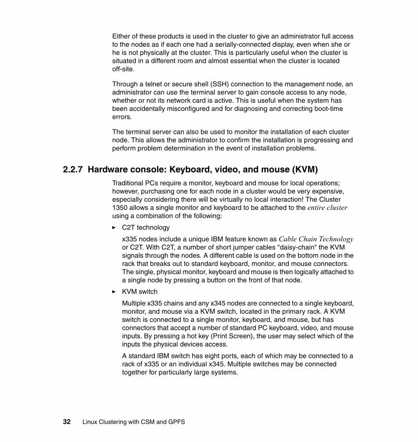
Either of these products is used in the cluster to give an administrator full access to the nodes as if each one had a serially-connected display, even when she or he is not physically at the cluster. This is particularly useful when the cluster is situated in a different room and almost essential when the cluster is located off-site.
Through a telnet or secure shell (SSH) connection to the management node, an administrator can use the terminal server to gain console access to any node, whether or not its network card is active. This is useful when the system has been accidentally misconfigured and for diagnosing and correcting boot-time errors.
The terminal server can also be used to monitor the installation of each cluster node. This allows the administrator to confirm the installation is progressing and perform problem determination in the event of installation problems.
2.2.7 Hardware console: Keyboard, video, and mouse (KVM)Traditional PCs require a monitor, keyboard and mouse for local operations; however, purchasing one for each node in a cluster would be very expensive, especially considering there will be virtually no local interaction! The Cluster 1350 allows a single monitor and keyboard to be attached to the entire cluster using a combination of the following:
� C2T technology
x335 nodes include a unique IBM feature known as Cable Chain Technology or C2T. With C2T, a number of short jumper cables "daisy-chain" the KVM signals through the nodes. A different cable is used on the bottom node in the rack that breaks out to standard keyboard, monitor, and mouse connectors. The single, physical monitor, keyboard and mouse is then logically attached to a single node by pressing a button on the front of that node.
� KVM switch
Multiple x335 chains and any x345 nodes are connected to a single keyboard, monitor, and mouse via a KVM switch, located in the primary rack. A KVM switch is connected to a single monitor, keyboard, and mouse, but has connectors that accept a number of standard PC keyboard, video, and mouse inputs. By pressing a hot key (Print Screen), the user may select which of the inputs the physical devices access.
A standard IBM switch has eight ports, each of which may be connected to a rack of x335 or an individual x345. Multiple switches may be connected together for particularly large systems.
32 Linux Clustering with CSM and GPFS

Monitor and keyboardThe single physical console installed in the management rack along with the KVM switch(es). A special 2U drawer houses a flat-panel monitor and a “space saver” keyboard that features a built-in track-point mouse, such as is found on IBM Thinkpads.
2.3 SoftwareAs mentioned previously, there is more to a cluster than simply servers in a rack. Another main component of the IBM Cluster 1350 is a set of software that includes the Linux operating system and the IBM Cluster Systems Management (CSM) for Linux. IBM General Parallel File System (GPFS) for Linux optionally can be included to provide high performance and parallel access to storage. Once the customer provides the Linux operating system, IBM Global Services can perform all the software installation and configuration.
The following sections provide a brief overview of each of the software components described above that are supported by IBM. The remaining chapters of this book addresses CSM and GPFS in more detail.
2.3.1 Linux operating systemAs discussed in Chapter 1, “Clustering concepts and general overview” on page 3, Linux is increasingly popular as an operating system. Due to its openness and relative cost, Linux-based clusters represent a very viable option for those wanting to utilize clustering to enhance availability, scalability, and/or processing power.
To provide a common base upon which the complex mixture of hardware and software that comprises a cluster could be consistently deployed, IBM chose to support a standard Linux distribution on the Cluster 1350. With its large user-base and automated "Kick-Start" installation, Red Hat Linux was the ideal choice.
The IBM Cluster 1350 offering is currently supported by multiple versions of both the Red Hat and SuSE distributions of Linux, for a complete list of supported versions, refer to 3.6, “Software requirements to run CSM” on page 67. The customer should provide the version of the Linux operating system specified by IBM. Additional Linux distributions and versions may be considered in the future.
Chapter 2. New Linux cluster offering from IBM: Cluster 1350 33

2.3.2 IBM Cluster Systems Management (CSM) for LinuxIBM Cluster Systems Management for Linux (CSM) provides a distributed system-management solution for clustered machines that are running the Linux operating system, as distributed by Red Hat. CSM is an IBM licensed program that forms an integral part of the IBM Cluster 1350 platform. It is also available as a separately orderable software product. Using CSM, an administrator can easily set up and maintain a Linux cluster by using functions like automated set up, hardware control, monitoring, and configuration file management. The concepts and software are derived from IBM Parallel System Support Programs for AIX (PSSP) and from applications available as open source tools.
CSM allows a cluster of nodes to be managed as a single entity from a single point of control: the management node. Hardware can be monitored and power controlled, software can be installed, configured, and monitored, and problems can be diagnosed from this single point of control using a command-line interface or script. There is no need to have keyboards and monitors attached to the nodes in the cluster, as all operations can be performed from a single management console using the functions discussed in the following list.
With the current version of CSM (1.3.1), it is possible to:
� Install Linux and/or CSM on cluster nodes over the network
� Add, remove, or change nodes
� Remote power control nodes in the cluster
� Access a node’s console remotely
� Run remote commands across groups of nodes in the cluster
� Centrally manage configuration files for the cluster
� Monitor nodes and applications as to whether they are active
� Monitor CPU, memory, and system utilization
� Run automated responses when events occur in the cluster
Each of these features is covered in greater detail later in the book, but for now we provide a brief overview.
Node installationCSM tools are able to perform either a CSM-only install or a Linux and CSM install (known as full-install) on each cluster node. For a complete explanation of these two installation methods, refer to:
� Chapter 5, “Cluster installation and configuration with CSM” on page 99 � 6.1.2, “Adding new nodes using the full installation process” on page 154
34 Linux Clustering with CSM and GPFS

Adding and removing nodesIBM understands that it may be difficult to accurately predict demand or growth within a company. With that in mind, adding or replacing nodes in a cluster with CSM is incredibly simple. Creating a new node definition and installing a node can easily be accomplished inside an hour, subject to network constraints. Removing nodes is equally simple.
Remote hardware controlThe service processors in all nodes of the cluster are accessible, via the RSAs, on the management VLAN and therefore to the cluster management node. This capability is used by CSM so the nodes may be powered on/off or reset remotely. Advanced system management functions, such as monitoring environmental conditions, are also available.
Remote consoleThis function uses the serial ports of the cluster servers and a terminal server to access cluster servers during Linux installation or when network access to the servers is unavailable. A single node’s console may be viewed or multiple consoles tiled across an X Windows® display to monitor installation progress.
Distributed shell (dsh)One of the most powerful and useful features of CSM, dsh allows the execution of arbitrary commands or scripts on all or some of the servers in the cluster. Via a simple command-line on the management node, the administrator may run any command she or he desires on a group of nodes.
Configuration File Manager (CFM) The CFM tool enables an administrator to set up configuration files in a central place. Configuration files are stored centrally on the management node and then pushed out to the cluster nodes. For any particular configuration file, the administrator can set up one version for all of the nodes or specify alternative versions that should be used for particular node groups. CFM can be configured so the nodes are updated automatically, periodically, or only when desired by the administrator.
Event monitoring and responseWithin a cluster, it is important that all the nodes remain operational, despite the stresses jobs may subject them to. CSM allows proactive monitoring of node resources with configurable response. Pre-defined monitors include file system or paging space approaching full, pre-defined responses, including sending e-mail to root and broadcast a message to all users. Additional monitors and responses may be configured and activated, even on a time-based schedule.
Chapter 2. New Linux cluster offering from IBM: Cluster 1350 35

2.3.3 General Parallel File System for LinuxA distributed file system is often critical to the operation of a cluster. If a high I/O throughput is required for a distributed file system, IBM General Parallel File System (GPFS) for Linux can be ordered with the IBM Cluster 1350 to provide high speed and reliable parallel storage access from large numbers of nodes within the cluster.
As the name suggests, GPFS is designed to allow multiple Linux nodes optimal access to the file system, even the same file, at the same time. It has been implemented so that, much like NFS, to the applications it looks just like any other file system. Unlike NFS, GPFS does not sit on top of an existing file system such as "ext2"; GPFS accesses local or network attached disks directly.
Concurrent reads and writes from multiple nodes is key in parallel processing. GPFS increases the concurrency and aggregate bandwidth of the file system by spreading reads and writes across multiple disks on multiple servers. Much as RAID-0 stripes read and write operations across multiple disks, GPFS stripes operations across multiple servers.
GPFS is a journalling file system and creates separate logs for each node. These logs record the allocation and modification of metadata, aiding in fast recovery and restoration of data consistency in the event of node failure. Additionally, fail-over support allows for automatic recovery in the event of a server node failure. GPFS can be configured with multiple copies of metadata (the file system data that describes the user data), allowing continued operation should the paths to a disk or the disk itself malfunction. Disks may be added or deleted while the file system is mounted.
GPFS data can be exported using Network File System (NFS), including the capability to export the same data from multiple nodes. This allows for some interesting possibilities in redundant NFS service.
GPFS provides the best performance for larger data objects, but can also provide benefits for large aggregates of smaller objects.
2.3.4 Other software considerationsOnce installed and configured, the IBM Cluster 1350 is equipped with everything you need to install, control, and manage hardware and operating system environments. However, there are additional software products that may be required for many clusters to provide the administrators and users with the tools they need to work efficiently. These include but are not limited to:
� Batch queuing systems� Advanced schedulers
36 Linux Clustering with CSM and GPFS

� Compilers� High availability software� Non-IBM distributed file systems� Parallel Programming Libraries
In addition, each of the applications that are expected to run on the cluster should be reviewed to understand what co-requisites or prerequisites each require. In the case of Linux, you should not only consider the version of Red Hat but the kernel version as well, and whether or not it is a custom-built kernel or one officially supported by Red Hat.
2.4 ServicesAs part of the IBM Cluster 1350, IBM includes services to help ensure the system is properly configured and make the installation and commissioning as smooth as possible.
Included in the purchase of every IBM Cluster 1350 are:
� Installation planning services� On-site installation� Warranty service and support
The following are examples of optional services that may be purchased with the IBM Cluster 1350:
� Project support services� Installation and customization� Continuing support services
2.4.1 Installation planning servicesA documented and agreed upon installation plan should be put in place to clarify key points prior to the IBM Cluster 1350 deployment. That should include:
� Site survey (for example, power, cooling, and floor considerations)� Each installation step and task to be performed� A comprehensive test plan
Chapter 2. New Linux cluster offering from IBM: Cluster 1350 37

2.4.2 On-site installation of the IBM eServer Cluster 1350The product has been integrated and tested at the factory and requires approximately four hours of a Customer Engineer's (CE) time for an average-sized cluster installation. Due to the shipping limitations of the racks, the CE must install one or two remaining components in the rack and will then power on the cluster and perform basic verification of the systems.
2.4.3 Warranty service and supportWarranty support is provided for the solution as a whole, IBM as well as non-IBM hardware components. The base warranty for IBM components is three years on-site support, next-business-day response. For non-IBM hardware, the manufacturers warranty applies.
During the warranty period, the customer is entitled to on-site parts and labor for warranty repair.
2.4.4 Project support servicesIBM recognizes that the procurement and installation of a cluster are a relatively small part of a much larger project. IBM can offer support for all phases of the undertaking, including systems integration, porting and tuning for the new platform, even helping with the development of new applications.
2.4.5 Installation and customizationIf you are unfamiliar with clustering or Linux, IBM can send a cluster specialist on-site to assist you in customizing the cluster to more closely meet your needs. The specialist will be able to cover areas such as operating system customization, GPFS installation, performance tuning of both Linux and GPFS, and general best practices. Skills transfer for the system administrators of the cluster is an important factor, along with the opportunity to query the expertise of an experienced person.
2.4.6 Continuing support servicesAlthough the hardware within the Cluster 1350 comes with the standard IBM warranty, it may be desirable to upgrade the level of support. Customers may elect to upgrade to a higher service level, such as 9x5 4-hour (same day) response or 7x24 4-hour response.
As well as upgraded warranty offerings, IBM offers extensive support for the cluster software as a whole. Support contracts are available that allow you to call
38 Linux Clustering with CSM and GPFS

IBM in the event of software failure or queries about any component of your IBM Cluster 1350.
2.5 SummaryIn this chapter, we have described a new offering from IBM intended to ease and speed the deployment of Linux-based clusters. The solution is designed to provide a set of hardware, software, and services to allow customers to start utilizing clustering technology.
Though this solution is designed to be functional on delivery; many customers will want to customize the solution over time, potentially reconfiguring, reinstalling, adding, or removing components. The rest of this redbook discusses the specifics of architecture, installation, and use of both CSM and GPFS to build, operate, and manage a Linux-based cluster.
Chapter 2. New Linux cluster offering from IBM: Cluster 1350 39

40 Linux Clustering with CSM and GPFS

Chapter 3. Introducing Cluster Systems Management for Linux
This chapter provides an architectural and functional overview of the IBM Cluster Systems Management (CSM) product. CSM is an integral component of the IBM Cluster 1350 solution.
A detailed installation process, including Linux and CSM installation in the cluster nodes, is presented in Chapter 5, “Cluster installation and configuration with CSM” on page 99. This chapter is designed for readers who need a quick overview of what CSM is and how it works. This chapter describes the different components of CSM and some of the steps involved in preparing to install and use the product.
The information in this chapter is based on CSM Version 1.3.1.
3
© Copyright IBM Corp. 2002, 2004 41

3.1 IBM Cluster Systems Management overviewThe purpose of the IBM Cluster Systems Management product (known as CSM throughout this book) is to provide broad management capabilities for clusters.
CSM provides many useful functions to manage a cluster from a single point of control. These include resource monitoring, automated monitoring and operation, remote hardware control, remote command execution, security, configuration file management, parallel network installation, and diagnostics. By consolidating these capabilities, CSM helps to increase utilization of an administrator’s time and reduce their expenses.
CSM provides a variety of other benefits:
� CSM helps administrators deploy their clusters rapidly by automating many configuration tasks and by leveraging existing Open Source products.
� CSM provides efficient monitoring of cluster resources without overwhelming network bandwidth.
� The automated error detection CSM provides helps catch problems before they impact the environment, and assists with rapid resolution and recovery of problems that occur.
� CSM has an architecture and modular construction that maximizes flexibility so your cluster solution can evolve and grow as your needs change.
The concept of CSM came from IBM Parallel System Support Programs for AIX (also known as PSSP) and from other applications available as open source tools.
CSM is a collection of components that have been integrated to provide the basis to construct and manage a cluster. Each of these components provides specific capabilities related to the management of the cluster. This component-based architecture provides flexibility for future expansion of the capabilities provided by CSM.
Each of the CSM components can be easily personalized to help meet specific needs. For example, a cluster administrator can set up monitoring of application processes and take actions if those processes disappear.
Underlying subsystems utilized by CSMCSM utilizes some underlying subsystems such as Resource Monitoring and Control (RMC), Reliable Scalable Cluster Technology (RSCT), and System Resource Controller (SRC), and adds on a set of programs to provide a wide range of capabilities around the complexities of managing large Linux clusters.
42 Linux Clustering with CSM and GPFS

The capabilities provided by the RMC, RSCT, and SRC subsystems allow CSM (as well as GPFS) to enable administrators to quickly deploy manageable clusters. CSM adds on top of this base a set of programs to add management functions, such as the Event Response Resource Manager, the Distributed Management Server, and the distributed shell. Both RSCT and SRC are described in detail in Appendix A, “SRC and RSCT” on page 253, and we cover RMC and the additional programs provided and used by CSM in this chapter.
3.2 CSM architectureThis section describes some of the basic concepts and technologies of CSM. These concepts and technologies provide the building blocks for the rich function provided by CSM. Most of them are inspired by the AIX PSSP software.
At the base, CSM programs use the Resource Monitoring and Control subsystem. The Resource Monitoring and Control subsystem uses the concept of resources.
A resource is a collection of attributes that describe or measure a logical or physical entity. A system or cluster is composed of numerous resources of various types.
The term resource is used very broadly in this architecture to refer to software as well as hardware entities. Examples of resources could be an IP address, an Ethernet card on eth0, and so on.
A set of resources that have similar characteristics in terms of services provided, configuration parameters, and so on, is called a Resource Class. Examples of resource classes include Ethernet adapters, token-ring adapters, network interfaces, and logical volumes.
3.2.1 Resource Monitoring and Control subsystemThe Resource Monitoring and Control (RMC) subsystem provides a generalized framework for managing and manipulating resources within a system or cluster. The framework allows a process on any node of the cluster to perform an operation on one or more resources elsewhere in the cluster. A client program specifies an operation to be performed and the resources it is to apply to through a programming interface called the RMCAPI. The RMC subsystem then determines the node or nodes that contain the resources to be operated on, transmits the requested operation to those nodes, and then invokes the appropriate code on those nodes to perform the operation against the resource.
Chapter 3. Introducing Cluster Systems Management for Linux 43

The Resource Monitoring and Control subsystem, as the basis of the CSM cluster, installs a daemon on each node inside the cluster. This daemon ultimately controls the resources on the node.
The daemon started by the Resource Monitoring and Control subsystem on each node is the /usr/sbin/rsct/bin/rmcd executable file.
3.2.2 CSM componentsAll the CSM components work together to provide general cluster management functions. These functions are summarized in Figure 3-1 and explained in more detail in the text that follows.
Figure 3-1 CSM architecture
Note: Notice that RMC clients running in a cluster only need a single connection to the RMC subsystem and do not have to deal with connection management for each node of the cluster. This makes it much easier to write management applications.
CSM Server
CSM Client
Database and DMS
ERRMHardware Control
Data
Install (kickstart, NIM, SIS)
dsh
CFM
Terminal Server
Compute Node
Installation
RMC Daemon
rsh (or ssh)
Hardware Control Point
Remote Console
RMC Daemon
rdist
Managed Node
Node Group
probemgrprobes
probemgrprobes
rpowerSensors
Logging
44 Linux Clustering with CSM and GPFS

Distributed shell (dsh)dsh provides the capability to execute a command across one or more cluster nodes. The individual responses from the nodes are then consolidated into a single output for the administrator who invoked the command.
The csm.gui.dcem package provides a graphical interface for this shell.
Availability monitorCSM uses the RMC subsystem to actively track the network availability of all the nodes in the cluster. Those nodes in the ManagedNode resource class are actively monitored, and their status attributes reflect the results.
Hardware controlThe hardware control functions provide the ability to do some basic operations on cluster nodes, like power on, power off, reset, or shutdown. These operations can be performed on a single node or a group of nodes.
All of this is done via the out-of-band path connected directly to the service processor for xSeries servers.
Remote hardware consoleCSM uses the remote hardware console to drive the operating system installation and other operations where the operating system or network is not available.
Either the MRV In-Reach Terminal Server or the Equinox Serial Provider provide the capability for the administrator to have direct access to whatever node he wants in the cluster. While the current CSM release supports only these terminal servers, there are multiple hardware solutions to provide this functionality.
Configuration File ManagementThe Configuration File Manager (CFM) gives the administrator the capability to define many configuration files (with variances for some machines) in a central place. An agent on each managed node then retrieves these modified files.
For any particular configuration file, the administrator can set up one version for all nodes, or can specify additional versions that should be used for particular types of machines or for a specific host name.
Each managed node can be instructed to pull the new configuration files at boot time, when files change, and/or when the administrator runs a command on the managed node.
This feature is very useful to distribute common files such as the /etc/hosts table.
Chapter 3. Introducing Cluster Systems Management for Linux 45

Database and Distributed Management Server (DMS)CSM needs a central place to store global or persistent data. For example, the list of machines in the cluster, information about each machine, what machines make up a node group, and so on.
CSM uses a two-part approach to accomplish this: the Distributed Management Server with a set of Resource Managers that provide the central coordination point for all of the management information, and a standard Perl database interface so that other tools can get at the information in a consistent way.
All of the CSM tools utilize Resource Managers to access the database information. This allows CSM to aggregate information from several sources that is not necessarily in the database or in the same format as the CSM database information.
DMS is comprised of the following resource classes:
� The ManagedNode resource class, which provides the central place to change and access the global node data. This includes periodically verifying node availability and caching the results for each node.
� The NodeGroup resource class.
� The PreManagedNode resource class, which is used internally to store information about nodes that are currently being installed or being prepared to join the cluster.
Event Response Resource Manager (ERRM)The ERRM component provides CSM the ability to run commands or scripts in response to user-defined events. An important set of predefined conditions and responses is provided in the CSM package. Many system resources can be monitored, including file systems, adapters, programs, and node availability. If needed, specific resources or components that are not predefined can be defined by the system administrator.
Predefined event condition and response actionsTo make the Resource Monitoring and Controlling subsystem and the Event Response Resource Manager useful to administrators, CSM supplies a set of event conditions and response actions that an administrator might typically want to use.
This gives the administrator a quick way to start monitoring the cluster right after its initial installation. The full list of predefined conditions can be found in 3.3.3, “Predefined conditions” on page 57, and the response list can be found in 3.3.4, “Responses” on page 59.
46 Linux Clustering with CSM and GPFS

Utilities for initial set upThis component includes the packaging and commands necessary to support the customer when installing and setting up a Linux cluster on both the management and managed nodes.
For more information on the installation process, see Chapter 5, “Cluster installation and configuration with CSM” on page 99.
Node groupsCSM has been designed to install and manage large clusters. To do that task efficiently, the notion of node groups has been implemented in the product.
The CSM database keeps track of all nodes in a cluster. The CSM agents that are running on nodes have access to data that could be collected by the management server.
It is possible to create fixed groups, for example, a group that contains only the machines installed in the first rack. By using the CSM agents, it is also possible to create and work with dynamic groups. This capability can be very useful for an administrator.
For example, suppose we want to know which nodes are running the Apache Web server in order to update them. The dynamic group function gives the administrator the ability to find all nodes that are running the httpd daemon and, with the dsh command, send to those nodes the appropriate commands to run.
The dynamic groups can use all parameters generated by the RMC components. Because RMC allows you to define new resources, CSM can be used to follow process-based or proprietary applications by searching for application-specific resources such as semaphores.
Agent Resource ManagerA Resource Monitoring and Controlling manager runs on each node that handles coordination issues between the node and its management server.
Initially, it has one resource class called ManagementServer, which deals with the management server. When a node joins a CSM cluster, this resource class contacts the management server to move its entry from the PreManagedNode table to the ManagedNode table and to verify that all information about it is correct.
SensorsSensors are customer-written scripts that run and retrieve one variable value from the system and make it known to the Resource Monitoring and Control
Chapter 3. Introducing Cluster Systems Management for Linux 47

subsystem. RMC event registrations and queries can be made against these variables.
The most common scenario would be for an administrator setting up one or more sensors to monitor variables that he cares about and then create ERRM conditions and responses to perform particular actions when the variables have certain values. This allows the administrator to control both sides of the RMC event pipe (detecting events and responding to them) simply by writing scripts.
A sensor Resource Manager manages the sensor scripts, running them periodically according to a specified interval. Each resource in the sensor Resource Manager represents the definition of one sensor, with information like the script command, what user name to run it under, and how often it should be run. The output of a sensor causes a dynamic variable within the resource to be set. It is this dynamic variable that can be queried or subscribed to by Resource Monitoring and Control clients (including ERRM).
LoggingCSM centralizes problems and informational messages into a single log file used by all CSM software. The size of the log file is monitored by CSM and archived when necessary.
3.2.3 Security in CSMThis section describes the mechanism used by CSM to authenticate the nodes and authorize them to perform actions. They are:
� Shell security� Authentication� Authorization
Shell securityCSM runs daemons on the cluster nodes under the root user. The shell used to communicate between all the cluster nodes by default is ssh.
This shell is used to establish a connection from the management server to the nodes itself. The SSH protocol and related ssh command is becoming the standard secure shell environment on Linux platforms. However, a cluster administrator may elect to replace ssh with another technology. See 5.2.10, “Deciding which remote shell protocol to use” on page 125 for more details about changing the default shell.
48 Linux Clustering with CSM and GPFS

AuthenticationCSM takes advantage of the authentication mechanism used by RSCT. This authentication mechanism is a host based authentication using private-public key pairs. Each node in the cluster has a unique private-public key pair.
The public key should be exchanged between the management server and the nodes for proper authentication of the requests. CSM automatically handles all the required key exchanges between the nodes of the cluster during installation and configuration. The public key is copied from each of the managed nodes to the management server, and the management server’s public key is copied to each of the managed nodes.
A CSM system administrator has control over the public and private keys used for cluster node security. Public and private keys are generated by cluster security services and used by cluster security services exploiters. These keys cannot be used with rsh, OpenSSH, or any other remote command technology. They are installed by default in the following locations:
� /var/ct/cfg/ct_has.qkf (private keys)� /var/ct/cfg/ct_has/pkf (public keys)� /var/ct/cfg/ct_has.thl (trusted host list)
AuthorizationCSM provides authorization in the form of an access control list (ACL) file.
This control list is used by the Resource Monitoring and Control subsystem to enable (or prevent) a user from executing a command that can change values on a class and its instances.
You can create the /var/ct/cfg/ctrmc.acls ACL file to apply access control to resource classes. If you do not modify the provided ACL file, then the system uses the default permissions, which allow the root account read/write access to all resource classes, and all other users are allowed read-only access, as shown in Example 3-1.
Example 3-1 Default CSM ACL in /var/ct/cfg/ctrmc.acls file
# The following stanza contains default ACL entries. These entries are appended# to each ACL defined for a resource class and are examined after any entries# explicitly defined for a resource class by the stanzas in this file,# including the OTHER stanza.
DEFAULT root@LOCALHOST * rw LOCALHOST * r
Chapter 3. Introducing Cluster Systems Management for Linux 49

� Read permission (r) allows you to register and unregister for events, to query attribute values, and to validate resource handles.
� Write permission (w) allows you to run all other command interfaces.
� No permissions are required to query the resource class and attribute definitions.
3.3 CSM monitoringOne of the key capabilities of CSM is to monitor the cluster resources and react to events. Therefore, the monitoring component in CSM is very important to understand.
This section does not presume to replace the Monitoring HowTo documentation, but rather is intended to provide the administrator with a basic understanding of the CSM monitoring architecture and components. Chapter 6, “Cluster management with CSM” on page 149 provides a great deal of information on how to manage a Linux cluster using CSM.
The following are definitions of the terms condition and response in the context of CSM.
Condition A measurement or status that a subsystem must reach to generate an alert, for example, more than 90 percent of CPU workload.
Response An action that is executed in response to a condition that has been encountered.
3.3.1 How CSM monitors a systemCSM uses Resource Managers to monitor a cluster. These Resource Managers use resource classes to update the attributes of the object representing the
Important: For any command issued against a resource class or its instances, the RMC subsystem examines the lines of the stanza matching the specified class in the order specified in the ACL file.
The first line that contains an identifier that matches the user issuing the command and an object type that matches the objects specified by the command is the line used to determine access permissions.
Therefore, lines containing more specific user identifiers and object types should be placed before lines containing less specific user identifiers and object types.
50 Linux Clustering with CSM and GPFS
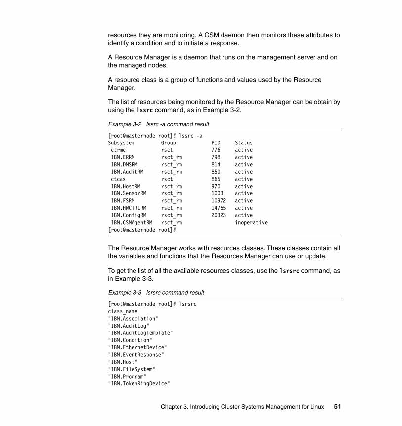
resources they are monitoring. A CSM daemon then monitors these attributes to identify a condition and to initiate a response.
A Resource Manager is a daemon that runs on the management server and on the managed nodes.
A resource class is a group of functions and values used by the Resource Manager.
The list of resources being monitored by the Resource Manager can be obtain by using the lssrc command, as in Example 3-2.
Example 3-2 lssrc -a command result
[root@masternode root]# lssrc -aSubsystem Group PID Status ctrmc rsct 776 active IBM.ERRM rsct_rm 798 active IBM.DMSRM rsct_rm 814 active IBM.AuditRM rsct_rm 850 active ctcas rsct 865 active IBM.HostRM rsct_rm 970 active IBM.SensorRM rsct_rm 1003 active IBM.FSRM rsct_rm 10972 active IBM.HWCTRLRM rsct_rm 14755 active IBM.ConfigRM rsct_rm 20323 active IBM.CSMAgentRM rsct_rm inoperative[root@masternode root]#
The Resource Manager works with resources classes. These classes contain all the variables and functions that the Resources Manager can use or update.
To get the list of all the available resources classes, use the lsrsrc command, as in Example 3-3.
Example 3-3 lsrsrc command result
[root@masternode root]# lsrsrcclass_name"IBM.Association""IBM.AuditLog""IBM.AuditLogTemplate""IBM.Condition""IBM.EthernetDevice""IBM.EventResponse""IBM.Host""IBM.FileSystem""IBM.Program""IBM.TokenRingDevice"
Chapter 3. Introducing Cluster Systems Management for Linux 51

"IBM.Sensor""IBM.ManagedNode""IBM.NodeGroup""IBM.ManagementServer""IBM.NodeAuthenticate""IBM.NetworkInterface""IBM.DmsCtrl""IBM.NodeHwCtrl""IBM.HwCtrlPoint""IBM.HostPublic"[root@masternode root]#
Resource classes contain a great deal of information. Some of this information is static (or persistent), like node hostname, and some is dynamic. Both static and dynamic values can be used to define conditions, but usually the dynamic values are used to set conditions. A static value in theory would not change, so a condition based on a static value is usually less interesting.
The static values of a class can be found with the lsrsrc -a p <class_name> command, where <class_name> is the name of the class, for example “IBM.Host”, and p specifies persistent values. Example 3-4 shows the static values from the IBM.Host class.
Example 3-4 lsrsrc -a p “IBM.Host” result
[root@masternode root]# lsrsrc -a p "IBM.Host"Resource Persistent Attributes for: IBM.Hostresource 1: Name = "masternode.cluster.com" NodeNameList = {"masternode.cluster.com"} NumProcessors = 2 RealMemSize = 1055698944 OSName = "Linux" KernelVersion = "2.4.18-10smp" DistributionName = "Red Hat" DistributionVersion = "7.3" Architecture = "i686"[root@masternode root]#
It is also possible to list the dynamic values of a class by typing the lsrsrc -a d <class_name> command, where <class_name> is the name of the class, for example “IBM.Host”, and d specifies dynamic values. Example 3-5 shows the dynamic values from the IBM.Host class.
Example 3-5 lsrsrc -a d “IBM.Host” output
[root@masternode root]# lsrsrc -a d "IBM.Host"Resource Dynamic Attributes for: IBM.Host
52 Linux Clustering with CSM and GPFS

resource 1: ActiveMgtScopes = 5 UpTime = 1635130 NumUsers = 9 LoadAverage = {0,0,0} VMPgSpOutRate = 0 VMPgSpInRate = 0 VMPgOutRate = 35 VMPgInRate = 0 PctRealMemFree = 1 PctTotalTimeKernel = 0.228220599793863 PctTotalTimeUser = 1.4116708831583 PctTotalTimeWait = 0.000412104445455916 PctTotalTimeIdle = 98.3596964126024 PctTotalPgSpFree = 99.626756733549 PctTotalPgSpUsed = 0.37324326645104 TotalPgSpFree = 522099 TotalPgSpSize = 524055[root@masternode root]#
It is also possible to get both static and persistent types of values by typing the lsrsrc -a b <class_name> command, where <class_name> is the name of the class and b specifies both persistent and dynamic values.
3.3.2 Resource ManagersThis section describes the CSM Resource Managers and explains the classes they use to manage the nodes. CSM resource managers are listed in Example 3-2 on page 51. These include the following:
� IBM.AuditRM (audit log)
� IBM.DMSRM (distributed management server)
� IBM.ERRM (event responses)
� IBM.FSRM (file system)
� IBM.HostRM (host)
� IBM.HWCTRLRM (hardware)
� IBM.SensorRM (sensor)
� IBM.CSMAgentRM (fundamentals)
� IBM.ConfigRM (network)
Chapter 3. Introducing Cluster Systems Management for Linux 53

IBM.AuditRM (audit log)This Resource Manager provides a system-wide facility for recording information about the system’s operations, which is particularly useful for tracking subsystems running in the background.
This Resource Manager has two resource classes: the IBM.AuditLog and the IBM.AuditLogTemplate.
These classes allow subsystems to manage logs (add, delete, and count records in log files).
There are no predefined conditions for these classes.
IBM.DMSRM (distributed management server)This Resource Manager manages a set of nodes that are part of a system management cluster. This includes monitoring the status of the nodes and adding, removing, and changing cluster nodes’ attributes.
This Resource Manager runs only on the management server.
This Resource Manager has four resources classes:
� IBM.ManagedNode� IBM.NodeGroup� IBM.NodeAuthenticate� IBM.DmsCtrl
The IBM.ManagedNode class provides information on a node and its status. The IBM.ManagedNode class has four predefined conditions, which are NodeReachability, NodeChanged, UpdatenodeFailedStatusChange, and NodePowerStatus. A list of all predefined conditions, along with their definitions, may be found in 3.3.3, “Predefined conditions” on page 57.
The IBM.NodeGroup class provides information about created groups. This class also contains the NodeGroupMembershipChanged predefined condition.
The IBM.NodeAuthenticate class hold the private and public keys information used to authenticate each CSM transaction between the management node and the managed node of a cluster. There are no predefined conditions for this class.
The IBM.DmsCtrl class provides CSM with information such as whether CSM should attend a management request from a unrecognized node or not, the maximum number of nodes allowed to be managed, the remote shell to be used by CSM applications, the type and model and serial number assigned to the cluster, and whether CSM should attempt to automatically set up remote shell access to the nodes in the cluster.
54 Linux Clustering with CSM and GPFS

IBM.ERRM (event response)This Resource Manager provides the ability to take actions in response to conditions occurring on the system. When an event occurs, ERRM runs user-configured or predefined scripts or commands.
The Event Response Manager use three classes:
� IBM.Condition� IBM.EventResponse� IBM.Association
The IBM.Condition class contains all of the defined conditions for the cluster.
The second class is the IBM.EventResponse class. This class contain all the responses that can be applied to an event.
The IBM.Association class contains the associations between conditions and responses.
IBM.FSRM (file system)This Resource Manager is used to monitor everything associated with file systems. It includes a list of all file systems, their status, and attributes such as the amount of space or i-nodes used, and so on.
The FSRM uses only one class, the IBM.FileSystem class. This class provides the Resource Manager all of the functions and data it needs to monitor a file system.
The IBM.FileSystem class has four predefined conditions, which are AnyNodeFilesystemInodesUsed, AnyNodeFilesystemSpaceUsed, AnyNodeTmpSpaceUsed, and AnyNodeVarSpaceUsed.
IBM.HostRM (host)This Resource Manager monitors resources related to an individual machine. The types of values that are provided relate to load (processes, paging space, and memory usage) and status of the operating system. It also monitors program activity from initiation until termination.
The IBM.Host Resource Manager use five classes of resources:
IBM.Host This class gives the Resource Manager the ability to monitor the paging space and total processor utilization. AnyNodePagingPercentSpaceFree and AnynodeProcessorsIdleTime are the two predefined conditions for this class.
Chapter 3. Introducing Cluster Systems Management for Linux 55

IBM.Program This class is used to monitor the set of processes that are running.
IBM.EthernetDevice This class is used to monitor Ethernet network interfaces, and provides interface statistics.
IBM.TokenRingDevice This class is used to monitor token ring network interfaces, and provides interface statistics.
IBM.HostPublic This class contains a public key used for transaction authentication.
IBM.HWCTRLRM (hardware)This Resource Manager is used to monitor node hardware. There are two resource classes associated with this resource manager.
The IBM.NodeHwCtrl class provides support for powering a node on and off, resetting a node, querying the power status of a node, resetting a node’s service processor, and resetting a node’s hardware control point. It provides CSM with node control information, such as the node hardware type, hardware model number, hardware serial number, host name of the network adapter for the console server, console method used to open node console, and MAC address of the network adapter used to perform node installations.
The IBM.HwCtrlPoint provides support for defining a node’s hardware control point. It contains information such as the power method used for a particular node, the time interval between power status queries, and the symbolic names of the nodes where the operational interface for hardware control is available.
IBM.SensorRM (sensor)This Resource Manager provides a means to create a single user-defined attribute to be monitored by the RMC subsystem.
This Resource Manager uses only one resource class: IBM.Sensor. This resource class enables you to create your own monitors. For example, a script can be written to return the number of users logged on to the system, then an ERRM condition and a response can be defined to run an action when the number of users logged on exceeds a certain threshold.
By default, the IBM.Sensor class has one predefined condition: CFMrootModTimeChanged. This condition is used to generated an event each time the /cfmroot directory is changed. Sensors are created using the mksensor command. The mksensor command adds an event sensor command to the Resource Monitoring and Control (RMC) subsystem.
56 Linux Clustering with CSM and GPFS
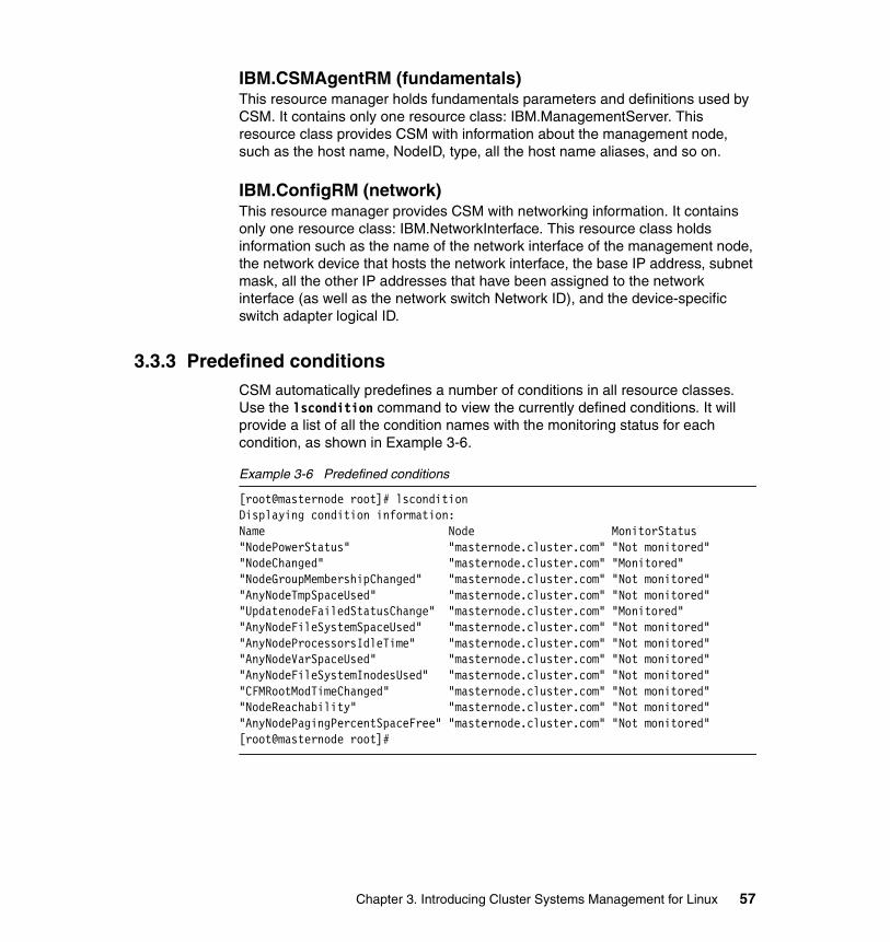
IBM.CSMAgentRM (fundamentals)This resource manager holds fundamentals parameters and definitions used by CSM. It contains only one resource class: IBM.ManagementServer. This resource class provides CSM with information about the management node, such as the host name, NodeID, type, all the host name aliases, and so on.
IBM.ConfigRM (network)This resource manager provides CSM with networking information. It contains only one resource class: IBM.NetworkInterface. This resource class holds information such as the name of the network interface of the management node, the network device that hosts the network interface, the base IP address, subnet mask, all the other IP addresses that have been assigned to the network interface (as well as the network switch Network ID), and the device-specific switch adapter logical ID.
3.3.3 Predefined conditionsCSM automatically predefines a number of conditions in all resource classes. Use the lscondition command to view the currently defined conditions. It will provide a list of all the condition names with the monitoring status for each condition, as shown in Example 3-6.
Example 3-6 Predefined conditions
[root@masternode root]# lsconditionDisplaying condition information:Name Node MonitorStatus"NodePowerStatus" "masternode.cluster.com" "Not monitored""NodeChanged" "masternode.cluster.com" "Monitored""NodeGroupMembershipChanged" "masternode.cluster.com" "Not monitored""AnyNodeTmpSpaceUsed" "masternode.cluster.com" "Not monitored""UpdatenodeFailedStatusChange" "masternode.cluster.com" "Monitored""AnyNodeFileSystemSpaceUsed" "masternode.cluster.com" "Not monitored""AnyNodeProcessorsIdleTime" "masternode.cluster.com" "Not monitored""AnyNodeVarSpaceUsed" "masternode.cluster.com" "Not monitored""AnyNodeFileSystemInodesUsed" "masternode.cluster.com" "Not monitored""CFMRootModTimeChanged" "masternode.cluster.com" "Not monitored""NodeReachability" "masternode.cluster.com" "Not monitored""AnyNodePagingPercentSpaceFree" "masternode.cluster.com" "Not monitored"[root@masternode root]#
Chapter 3. Introducing Cluster Systems Management for Linux 57

Here we provide a description of all the conditions that are predefined in all resource classes:
� NodePowerStatus
An event will be generated whenever the power status of the node is no longer 1 (1 means power is on). This will typically happen either when the node is powered off or the power status of the node cannot be determined for some reason. A rearm event will be generated when the node is powered up again.
� NodeChanged
An event is generated when a node definition in the ManagedNode resource class changes.
� NodeGroupMembershipChanged
An event will be generated whenever a node is added to or deleted from a previously existing NodeGroup.
� AnyNodeTmpSpaceUsed
An event is generated when more than 90% of the total space in the /tmp directory is in use. The event is rearmed when the percentage of space used in the /tmp directory falls below 75%.
� UpdatenodeFailedStatusChange
An event will be generated when a node on which the updatenode command failed now has online status.
� AnyNodeFileSystemSpaceUsed
An event is generated when more than 90% of the total space in the file system is in use. The event is rearmed when the percentage of space used in the file system falls below 75%.
� AnyNodeProcessorsIdleTime
An event is generated when the average time all processors are idle is at least 70% of the time. The event is rearmed when the idle time decreases below 10%.
� AnyNodeVarSpaceUsed
An event is generated when more than 90% of the total space in the /var directory is in use. The event is rearmed when the percentage of space used in the /var directory falls below 75%.
58 Linux Clustering with CSM and GPFS
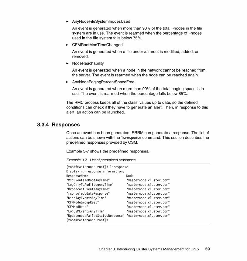
� AnyNodeFileSystemInodesUsed
An event is generated when more than 90% of the total i-nodes in the file system are in use. The event is rearmed when the percentage of i-nodes used in the file system falls below 75%.
� CFMRootModTimeChanged
An event is generated when a file under /cfmroot is modified, added, or removed.
� NodeReachability
An event is generated when a node in the network cannot be reached from the server. The event is rearmed when the node can be reached again.
� AnyNodePagingPercentSpaceFree
An event is generated when more than 90% of the total paging space is in use. The event is rearmed when the percentage falls below 85%.
The RMC process keeps all of the class’ values up to date, so the defined conditions can check if they have to generate an alert. Then, in response to this alert, an action can be launched.
3.3.4 ResponsesOnce an event has been generated, ERRM can generate a response. The list of actions can be shown with the lsresponse command. This section describes the predefined responses provided by CSM.
Example 3-7 shows the predefined responses.
Example 3-7 List of predefined responses
[root@masternode root]# lsresponseDisplaying response information:ResponseName Node"MsgEventsToRootAnyTime" "masternode.cluster.com""LogOnlyToAuditLogAnyTime" "masternode.cluster.com""BroadcastEventsAnyTime" "masternode.cluster.com""rconsoleUpdateResponse" "masternode.cluster.com""DisplayEventsAnyTime" "masternode.cluster.com""CFMNodeGroupResp" "masternode.cluster.com""CFMModResp" "masternode.cluster.com""LogCSMEventsAnyTime" "masternode.cluster.com""UpdatenodeFailedStatusResponse" "masternode.cluster.com"[root@masternode root]#
Chapter 3. Introducing Cluster Systems Management for Linux 59

The responses in CSM are scripts or commands. The following list describes what each of the responses does and the associated scripts or commands:
� MsgEventsToRootAnyTime
Command: /usr/sbin/rsct/bin/msgevent root
This response send a message to a specified user (in this example, to the user root).
� LogOnlyToAuditLogAnyTime
This response simply logs an event in the audit log, but does not take any action.
� BroadcastEventsAnyTime
Command: /usr/sbin/rsct/bin/wallevent
This response sends an event or a rearm event to all users who are logged in.
� rconsoleUpdateResponse
Command: /opt/csm/csmbin/rconsoleUpdate_response
This response runs an internal command that is used as part of the automatic rconsole configuration file update facility.
� DisplayEventsAnyTime
Command: /usr/sbin/rsct/bin/displayevent admindesktop:0
This response notifies a user of an event by displaying it on her X Window console, here the admindesktop:0 console.
� CFMNodeGroupResp
Command: /opt/csm/csmbin/CFMnodegroupresp
This response is used internally to determine whether changed files in /cfmroot belong to a particular NodeGroup.
� CFMModResp
Command: /opt/csm/csmbin/CFMmodresp
This response is used internally to perform an update to all nodes when the /cfmroot directory changes.
� LogCSMEventsAnyTime
Command: /usr/sbin/rsct/bin/logevent /var/log/csm/systemEvents
This response logs events to the /var/log/csm/systemEvents file.
60 Linux Clustering with CSM and GPFS

� UpdatenodeFailedStatusResponse
Command: /opt/csm/csmbin/updatenodeStatusResponse
Once the condition UpdatenodeFailedStatusChange generates an event when a node that previously did not complete updatenode is back online, the response UpdatenodeFailedStatusResponse re-runs the updatenode command on those particular nodes.
Of course, the above list of responses is limited to the predefined ones. CSM provides some commands to create, modify, or delete responses. The name of the commands are mostly self-explanatory.
The lsresponse lists all the defined responses, chresponse adds or changes actions included in a response, rmresponse deletes the response, and mkresponse creates a new response. Refer to Chapter 6, “Cluster management with CSM” on page 149 for details.
3.3.5 Associating conditions and responsesAs already discussed, CSM provides predefined conditions and responses to the cluster administrator to help him in his management role, but the conditions and the responses are not linked together by default.
To be effective, conditions and the responses need to be linked together and a monitor started. This section provides an example of how to form this association.
To see what condition/response associations already exist, type the lscondresp command. Example 3-8 shows what the output of the lscondresp command should look like immediately after installing CSM.
Example 3-8 List of predefined associations
[root@masternode root]# lscondrespDisplaying condition with response information:Condition Response Node State"UpdatenodeFailedStatusChange" "UpdatenodeFailedStatusResponse" "masternode" "Active""NodeChanged" "rconsoleUpdateResponse" "masternode" "Active"[root@masternode root]#
The startcondresp command is used to create condition/response relationships and begin actively monitoring them.
Note: The command output shown in has been edited to fit in the allotted space. The Node column originally shows the fully qualified name of your management node, in our case, masternode.cluster.com.
Chapter 3. Introducing Cluster Systems Management for Linux 61

The lsaudrec command may be used to review ERRM audit logs. Use rmaudrec to remove records from the audit logs.
The stopcondresp and rmcondresp commands are used to temporarily stop monitoring and permanently remove condition/response associations, respectively.
For more details on managing condition/response associations, including command syntax and examples, see 6.7.1, “RMC components” on page 174.
3.3.6 Creating new conditions and responsesThe predefined conditions and responses may not always meet the needs of the cluster administrator. Therefore, the administrator can create new conditions and new responses to meet his/her requirements.
The mkcondition and mkresponse commands may be used to implement locally required event tracking. Refer to 6.7.4, “Creating your own conditions and responses” on page 179 for an example of creating and using a custom condition and response.
If the predefined conditions and responses are not a good match for your environment, it is possible to remove or recreate them by using the predefined-condresp command.
3.4 CSM management componentsCSM provides several components that give the administrator tools to manage the cluster. This section describes some of the most important CSM components. For the most part, the commands described are the commands that have to be used to perform the full cluster installation and to begin managing the cluster.
3.4.1 Node and group management commandsThe group notion is very important in a cluster environment. CSM has been designed to provide the cluster administrator with flexible functions to manage groups or nodes. Groups are used often by several components of CSM, such as the Configuration File Manager and the distributed shell.
Important: By default, some conditions and responses are created but are not associated. The administrator would have to link conditions with responses to begin using this facility to manage the cluster.
62 Linux Clustering with CSM and GPFS

The main node and group commands are the following:
� definenode
This command predefines a node that will be inserted in the cluster database when the node installation is completed. It does not install the node.
� installnode
This command installs the nodes that have been predefined. At the end of a successful installation process, the node will be inserted in the cluster database.
� lsnode
This command lists the managed node definitions in the IBM Cluster Systems Management database.
� chnode
This command changes a node definition in the cluster database.
� rmnode
This command removes a node definition from the cluster database. CSM will not manage this node anymore.
� nodegrp
This command is used to create or delete static or dynamic groups.
3.4.2 Controlling the hardwareCSM uses specific facilities to control nodes. Primarily, the hardware control is based on the Advanced System Management (ASM) processor, which is on the motherboard of Model 335 and Model 345 machines. CSM also offers control via MRV In-Reach Terminal Server (MRV) or Equinox Serial Provider (ESP) hardware.
The ASM processor monitors the machine itself for conditions like disk failures, CPU or motherboard over-heating, fan failures, and so on. It also is used to control the machine power status and can be used to start, stop, or reboot a node.
The MRV or ESP provide the cluster administrator with the capability to monitor all of the nodes as if he had individual consoles for each.
Chapter 3. Introducing Cluster Systems Management for Linux 63

There are two commands available to control the nodes:
� rpower
This command gives the administrator the capability to power on, power off, or restart a node or a group of nodes. This command use the ASM processor to control the machine. It can work with or without a running operating system on the node(s).
� rconsole
The rconsole command can be used with a node or group. It opens an xterm window on the management server for each node selected. The font size used will be adapted to the number of open nodes. There is also an option to view a single console via the current terminal session for administrators outside of an X Windows environment.
This command uses the MRV In-Reach or Equinox Serial Provider hardware to connect to the node through its serial port.
3.4.3 Using DSH to run commands remotelyTo allow an administrator to manage a large number of nodes concurrently, CSM uses a distributed shell capability. This allows an administrator to execute the same command on multiple machines from a single console. This could be accomplished in a variety of ways, but if this command generates output, it could be very difficult for the administrator to interpret all of the returned data and associate errors with individual nodes. Therefore, CSM’s distributed shell facility helps to organize and display the command output in a way that makes it easy for the administrator to see the results.
� dsh
The dsh command can be used with nodes or groups and can be run from any node, assuming that the appropriate security definitions have been implemented.
The dsh command output is not formatted node-per-node. See the dshbak command to format the dsh result to a more readable output when multiple nodes are involved.
� dshbak
The dshbak command is actually a filter rather than a stand-alone tool. This command works closely with the dsh command to format the results in a readable way. The syntax is:
dsh -a date | dshbak
Output from the dsh command is captured by dshbak and displayed on a per-node basis.
64 Linux Clustering with CSM and GPFS
CSM also installs the Distributed Command Execution Manager (DCEM) graphical user interface, which provides a variety of services for a network of distributed machines. DCEM allows you to construct command specifications for executing on multiple target machines, providing real-time status as commands are executed. You can enter the command definition, run-time options, and selected hosts and groups for a command specification, and you have the option of saving this command specification to use in the future. It allows the administrator to define dynamic groups so that the targets of a specific command can be programmatically determined when the command is executed. For a complete description of the DCEM functions, refer to the IBM Cluster Systems Management for Linux: Administration Guide, SA22-7873.
3.4.4 Configuration File Manager (CFM)The Configuration File Manager is used by CSM to replicate common files across multiple nodes. For example, common files like the /etc/hosts or the /etc/passwd file often need to be identical (or close to identical) across all nodes in a cluster. When a change is made, these changes need to be duplicated. CFM makes this process much simpler.
Using CFM, each node could ask the management server periodically if files have been updated, and, if so, to download them. Also, the administrator can force the nodes to do a replication.
CFM allows you to define multiple instances of the same file, which could be assigned to different cluster parts. For example, the compute nodes could have a certain requirement for the /etc/hosts file, while the storage nodes that are visible from outside the cluster may require a different version.
CFM can also handle the conditions where a node may be unavailable, by ensuring the files are synchronized once the node returns to active status.
The following commands are the most common for managing CFM:
� cfm
The cfm command is used to start the CFM service. This command should not be run at the command line. It should be automatically started on the management server during system boot.
� cfmupdatenode
The cfmupdatenode command requires a node to do a synchronization with the management server without waiting for the next scheduled update.
Chapter 3. Introducing Cluster Systems Management for Linux 65

3.5 CSM hardware requirementsNow that we have a basic understanding of CSM and its capabilities, let us look at the hardware that is required to use CSM in a cluster. The IBM Cluster 1350 includes support for CSM, and CSM is shipped as part of the offering. If you are not using the IBM Cluster 1350, then you need to verify that you have all of the necessary hardware described in this section.
For this redbook, we concentrate our effort on the IBM Cluster 1350 only. See Chapter 2, “New Linux cluster offering from IBM: Cluster 1350” on page 21 for more information about the IBM Cluster 1350 offering.
3.5.1 Minimum hardware requirementsAs the IBM Cluster 1350 is a customizable platform, it is useful to know the minimum requirements to run CSM.
Management serverThis server is used to manage the cluster. To install CSM, this machine needs at least 128 MB of memory and 1.5 GB of storage for the full CSM installation.
This server supports the MRV In-Reach Terminal Server or the Equinox Serial Provider equipment.
Managed nodesThe managed nodes need at least 128 MB of memory and 20 MB of disk space to run CSM.
Depending on the cluster configuration, these nodes may also support a Myrinet adapter.
Network requirementsCSM requires the TCP/IP protocol and at least one Ethernet adapter.
At the management server, it is highly recommended that eth0 be used for the cluster VLAN, and another Ethernet card used for the management VLAN.
If the management server is also providing the user node capability (the machine that receives user connections and requests), then a third card should be added (on a different subnet) with appropriate access rules to secure the cluster.
66 Linux Clustering with CSM and GPFS
Remote control hardware requirementsCSM uses remote control hardware during the installation process to reboot the nodes and to retrieve their MAC addresses. Without this hardware, the installation is still possible, but not in an automatic way. It would be much more complicated because each node’s MAC address would have to be inserted in the cluster database individually.
CSM also provides the ability to develop special scripts to manage specific hardware, like the American Power Conversion (APC) Master Switch, which can be use to manage non-validated components.
The CSM rconsole command uses, by default, an MRV In-Reach (8000 Series) 20 or 40 port Terminal Server or an 8 or 16 port Equinox Serial Provider to communicate between the management server and the cluster nodes.
LimitationsAt the time of the writing of this book, CSM is limited to a cluster of up to 512 nodes. This limitation will likely change to higher numbers of nodes in future releases.
3.6 Software requirements to run CSMAt the time of writing this book, CSM 1.3.1 provides support for the following operating systems on a wide range of IBM based hardware:
� Red Hat Linux 7.2� Red Hat Linux 7.3� Red Hat Linux AS 2.1� Red Hat Linux 8.0� SuSE 8.0� SuSE 8.1� SuSE SLES 7 (7.2)� SuSE SLES 8.0
Attention: You should pay attention to securing the management server, because it could directly act on all cluster nodes, and a security hole could be dangerous for data and cluster integrity.
Note: Some of the non-IBM software that is required by CSM to function correctly and is not shipped with either the Red Hat or SuSE Linux distributions, but can be found on the CSM CD-ROM.
Chapter 3. Introducing Cluster Systems Management for Linux 67

3.6.1 IBM CSM software packagesCSM depends on multiple components. Most of the components need to be installed on each of the cluster machines, but some are only needed on the management server. The CSM package comes with one CD that contains all of the IBM software packages and all of the needed components that are not included on the Linux Operating System media.
The IBM CSM software packages are the following:
� csm.client
This package is installed only on the managed nodes and contains the CSM Agent Resource Manager, serial console support, man pages, and client configuration scripts.
� csm.core
This package contains all necessary utilities for CSM and other tools. It provides the CSM basic commands (lsnode, chnode, and so on), hardware control commands, console control commands, and Configuration File Manager files.
� csm.server
This package contains the CSM server side tools, like installation tools, Resource Manager code, and documentation. It is useful only on the management server.
� csm.dsh
This package contains the distributed shell, which provides the capability to run commands remotely on multiple machines.
� csm.gui.dcem
This package contains the GUI for the distributed shell. It will be installed on the management server only.
� csm.diagnostics
This package provides a set of probes to diagnose software problems on your system. A set of base probes are supplied with this RPM, but users can also add their own probes.
� csm.director.agent
This package contains agent-side components of the Linux CSM Cluster Support extension for IBM Director.
� csm.director.server
This package contains server-side components of the Linux CSM Cluster Support extension for IBM Director.
68 Linux Clustering with CSM and GPFS

� csm.director.console
This package contains console components of the Linux CSM Cluster Support extension for IBM Director.
� rsct.core
This package installs the IBM Reliable Scalable Cluster Technology (RSCT) software. RSCT software provides a set of services that support high availability on a system by supervising coherency between groups of services.
� rsct.core.utils
This is a set of tools used by RSCT.
� rsct.basic
This package adds functions to the RSCT component. It is not needed for a basic installation of CSM, but, if you intend to run GPFS on this cluster, then it should be installed.
� src
This package installs the System Resource Controller. It works closely with the RSCT package by giving to it a set of tools used to control and monitor subsystems.
3.6.2 Third party software componentsSome non-IBM software packages are required to run CSM. Some of them are included on the Linux Operating System distribution media, while the remainder are provided on the CSM media. Since we have been concentrating on the IBM
Cluster 1350, here we provide a list of packages that are shipped with Red Hat Linux 7.3.
Packages included on Red Hat Linux 7.3 mediaCSM uses Red Hat 7.3 and the following packages to install the cluster:
� Expect 5.32.2-67 (on management server only)
Expect is used in CSM to automate operations that need some interaction on the cluster nodes, like ssh, and so on.
� dchp 2.0p15-8 (on management server only)
This is the dhcpd deamon, which is used to assign IP addresses to the managed nodes during their installation. When the installation is finished, the IP addresses are fixed on each node and dhcp is not used any more until the next installation.
Chapter 3. Introducing Cluster Systems Management for Linux 69

� glibc 2.2.5-39
This is a library used by binaries.
� libstdc++ 2.96-110
This is a library used by binaries.
� pdksh 5.2.14-16
This is a public version of the Korn shell.
� perl 5.6.1-34.99.6
Perl is a high-level programming language. Many of the CSM scripts are written in Perl.
� make 3.79.1-8
This software is used to generate executable files.
� nfs-utils 0.3.3-5 (on management server only)
This package adds Network File System (NFS) tools.
� tcl-8.3.3-67
Tcl is a simple scripting language used as a building block for higher-level applications, including CSM hardware control.
� tk-8.3.3-67
The tk package contains graphical libraries and tools to complement Tcl.
� XFree86-libs-4.2.0-8
XFree86-libs contains the shared libraries required for running X applications.
� freetype-2.0.9-2
This package is a free and portable TrueType font rendering engine. FreeType provides a API to access font content in a uniform way, independently of the file format.
� rdist-6.1.5-16
The RDist program maintains identical copies of files on multiple hosts.
Important: To be able to configure the Equinox Serial Provider, it is mandatory to install the uucp package from the Red Hat Linux media. This package is not installed by default either by the Red Hat Linux installation or by the CSM package.
70 Linux Clustering with CSM and GPFS

Additional packages not included in Red Hat Linux 7.3The following packages are needed by CSM but are not provided on the Red Hat Linux 7.3 media. All of these packages are provided on the CSM CD and are automatically installed during the install process.
� atftp 0.3-1
This package implements the TFTP protocol on the cluster. It is used in the node installation procedure.
� SYSlinux 1.64-1
This utility is a boot loader for Linux that can be run from an MS-DOS floppy.
� IBMJava2-JRE-1.3-13.0
This package is the IBM Java™ Runtime Environment for Linux, Java2(TM) Technology Edition.
� conserver-7.2.2-3
This utility allows multiple users to watch a serial console at the same time.
� perl-libnet-1.0703-6
The libnet module for perl, which provides a client API to various network protocols, such as FTP. It is used by CSM for software maintenance and interoperability.
� autoupdate-4.3.4-1
AutoUpdate is a simple Perl script that performs a task similar to Red Hat's up2date or autorpm commands. It is used to synchronize updates across the cluster.
� ITDAgent-4.10-1
ITDAgent is a core piece of IBM Director, an integrated systems management software solution for application, server, and desktop management.
Important: If you intend to run CSM and GPFS on the same cluster, you need to install CSM client package on all or none of the GPFS nodes.
The Resource Monitoring and Control subsystem requires that the definition of its resource classes be the same on all nodes within the GPFS cluster.
Also, the CSM management server node should not be part of the GPFS cluster because it adds other resource classes to the Resource Monitoring and Control subsystem, and it is not desirable to install the csm.server package on all of the GPFS nodes.
Chapter 3. Introducing Cluster Systems Management for Linux 71

3.7 Quick installation process overviewThis section describes the installation process from a general point of view. It describes the steps to install CSM on a cluster but does not provide any details. The details of the installation process are covered in Chapter 5, “Cluster installation and configuration with CSM” on page 99.
Planning the installationBefore starting, it is important to plan the installation by sizing the nodes, defining the storage need, defining the type of networks used for the cluster VLAN, the management VLAN, user access, and the IP addresses that will be used.
Hardware preparationOnce the hardware choices have been made, the hardware needs to be prepared for use in the cluster. The system’s BIOS should be modified to boot from the network as well. This is only an example of the type of preparation that must be done before the installation.
For the storage nodes or the management server, the preparation needs to include the RAID arrays definition.
It is preferable also to be sure that all nodes based on the same hardware in the cluster are at the same level of firmware and BIOS.
Populate the rack and cablingNext, the rack needs to be physically installed and the cabling needs to be attached, as defined in the planning stage.
Configuring the Remote System AdapterAs the Remote System Adapter (RSA) will be used by the cluster installation process, it has to be set up before starting the software installation.
Install Linux and CSM and configure the management serverThe management server is the only machine that cannot be installed by CSM. The management server will be used to install the other cluster nodes. The Linux installation should also include the Red Hat updates packages, the MRV In-Reach Terminal Server or Equinox Serial Provider installation and configuration, and the CSM software packages.
CSM nodes definition and installationAt this point the management server is installed and configured. The nodes now need to be defined and installed. After the nodes are created in the cluster
72 Linux Clustering with CSM and GPFS
database, CSM finishes the installation for you (including the operating system and the CSM installation).
The cluster is now operational and ready to perform real work.
3.8 CSM futuresCSM is constantly evolving to add new capabilities. More and more tools coming from the pSeries® platform or from the Open Source community are included in CSM. Here are some examples of possible enhancements to CSM that may be included in future releases:
� Support for a higher number of nodes
� Support for additional hardware by using pluggable modules
� Multiple management servers for better scaling and fail-over operations
� Support for a mixed AIX and Linux environment inside the same cluster
� Kerberos Version 5 support
� Centralized logging
� Support for additional Linux distributions
3.9 SummaryCSM provides many useful functions to manage a cluster from a single point of control. This chapter has given a general overview of the architecture and functions of CSM.
The primary facilities provided by CSM include:
� Resource monitoring and operation� Remote hardware control� Remote command execution� Configuration File Management� Parallel network installation
Details related to the installation and use of CSM are provided in Chapter 5, “Cluster installation and configuration with CSM” on page 99 and Chapter 6, “Cluster management with CSM” on page 149.
Important: The above are possible enhancements, but they must not be considered as commitments from IBM to deliver these new functions in future releases of CSM.
Chapter 3. Introducing Cluster Systems Management for Linux 73

74 Linux Clustering with CSM and GPFS

Chapter 4. Introducing General Parallel File System for Linux
This chapter provides an overview of the General Parallel File System (GPFS) architecture, components, and terminology. It also describes the different kinds of implementations that can be used with the product.
4
© Copyright IBM Corp. 2002, 2004 75

4.1 Introduction to GPFSIBM General Parallel File System is the IBM's first shared disk file system. It was initially released on the RS/6000® SP in 1998 using a software simulation of a storage area network called the IBM Virtual Shared Disk (VSD). At its core, GPFS is a parallel disk file system. The parallel nature of GPFS guarantees that the entire file system is available to all nodes within a defined scope and the file system's services can be safely applied to the same file system on multiple nodes simultaneously.
The IBM General Parallel File System allows users shared access to files that may span multiple disk drives on multiple nodes. It offers many of the standard UNIX file system interfaces, allowing most applications to execute without modification or recompiling. UNIX file system utilities are also supported by GPFS. That is, users can continue to use the UNIX commands they have always used for ordinary file operations. The only new commands are those for administering the GPFS file system.
GPFS provides file system services to parallel and serial applications. GPFS allows parallel applications simultaneously access to the same files, or different files, from any node in GPFS node group while managing a high level of control over all file system operations (see GPFS nodeset).
GPFS is particularly appropriate in an environment where the aggregate peak need for data exceeds the capability of a distributed file system server. It is not appropriate for those environments where hot backup is the main requirement or where data is readily partitioned along individual node boundaries.
This chapter primarily addresses GPFS Version 1.3.0, which was the most current version when this book was written.
4.1.1 GPFS terms and definitionsThere are many terms that are used by GPFS. Some are unique to GPFS and some are more general, but to prevent confusion we cover these terms in this section.
GPFS clusterA GPFS cluster is a collection of nodes with a shared-disk file system that can provide data access from all nodes in a cluster environment concurrently.
GPFS nodesetA GPFS nodeset is a group of nodes that all run the same level of GPFS code and operate on the same file systems.
76 Linux Clustering with CSM and GPFS

GPFS Open Source Portability LayerThe GPFS Open Source Portability Layer is a set of source files that can be compiled to provide Linux kernel abstraction layer for GPFS and is used to enable communication between the Linux kernel and the GPFS kernel modules.
GPFS Network Shared Disk (NSD)GPFS Network Shared Disk (NSD) is a GPFS disk subsystem that provides remote disk capability and global disk naming for GPFS shared-disk file system.
Failure groupA failure group is a set of disks that share a common point of failure that could cause them all to become simultaneously unavailable.
MetadataMetadata consists of i-nodes and indirect blocks that contains file size, time of last modification, and addresses of all disk blocks that comprise the file data. It is used to locate and organize user data contained in GPFS’s striped blocks.
QuorumQuorum is a simple rule to ensure the integrity of a cluster and the resources under its administration. In GPFS, quorum is achieved if GPFS daemons in at least half of all nodes are in the active state and are able to communicate with each other.
4.1.2 What is new in GPFS for Linux Version 1.3There are several enhancements in Version 1.3:
� Support for IBM Cluster 1300 or an IBM Cluster 1350 with:
– Red Hat Linux 7.2 with a minimum kernel level of 2.4.9-34
– Red Hat Linux 7.3 with a minimum kernel level 2.4.18-3
– SuSE Linux Enterprise Server 7 with minimum kernel level of 2.4.18-64GB-SMP
� Maximum GPFS nodeset size of 256 IBM xSeries machines.
� The capability to read from or write to a file with direct I/O. The Direct I/O caching policy bypasses file cache and transfers data directly from disk into the user space buffer, as opposed to using the normal cache policy of placing pages in kernel memory. Applications with poor cache hit rates or very large I/Os may benefit from the use of Direct I/O.
Chapter 4. Introducing General Parallel File System for Linux 77

4.1.3 GPFS advantagesGPFS provides several advantages when building a cluster. We have summarized some of these here:
� Improved system performance
GPFS capabilities allow multiple processes or applications on all nodes in the nodeset simultaneous access (concurrent reads and writes from multiple nodes) to the same file using standard file system calls. It uses all the nodes in a nodeset to increase the file system bandwidth by spreading reads and writes across multiple disks. The load balancing across the system avoids one disk being more active than another.
� Assured configuration and file consistency
GPFS uses a sophisticated token management system to provide data consistency while allowing multiple, independent paths to the same file, by the same name, from anywhere in the nodeset. Even when nodes are down or hardware resource demands are high, GPFS can find an available path to file system data.
� High recoverability and increased data availability
GPFS is a logging file system that creates separate logs for each node. These logs record the allocation and modification of metadata, aiding in fast recovery and the restoration of data consistency in the event of node failure.
GPFS fail-over support allows you to organize your hardware to minimize single points of failure. Plan to organize your disks into a number of failure groups.
In order to assure data availability, GPFS maintains each instance of replicated data on disks in different failure groups. Even if you do not specify replication when creating a file system, GPFS automatically replicates recovery logs in separate failure groups.
� Enhanced system flexibility
With GPFS, your system resources are not frozen. You can add or delete disks while the file system is mounted.
When the time is right and system demand is low, you can re-balance the file system across all currently configured disks.
You can also add new nodes without having to stop and restart the GPFS daemon.
After GPFS has been configured for your system, depending on your applications, hardware, and workload, you can reconfigure GPFS to increase throughput.
78 Linux Clustering with CSM and GPFS

� Simplified administration
GPFS administration commands are designed to keep configuration and file system information synchronized between each nodes, and with GPFS system files on each node in the nodeset, most GPFS administration tasks can be performed from any node running GPFS.
4.2 GPFS architectureThis section describes the internal architecture, components, and technologies that make up GPFS.
4.2.1 GPFS componentsGPFS is based on the following components:
� A kernel extension� GPFS daemon� RSCT daemons� Portability layer module
Figure 4-1 shows these GPFS components.
Figure 4-1 GPFS components
Linux Operating System
IBM Reliable Scalable Cluster Technology (RSCT)
Group Services (hagsd) Topology Services (hatsd)
SystemResourceController
(SRC)
General Parallel File System (GPFS)
GPFS daemon(mmfsd)
Portability layer module
(mmfslinux)GPFS kernel module
extension (mmfs)
Chapter 4. Introducing General Parallel File System for Linux 79

The GPFS kernel module extension (mmfs)The kernel extension provides the interfaces to the virtual file system (VFS) for accessing a file system.
Structurally, applications issue file system calls to the operating system, which in turn presents the calls to the GPFS file system kernel extension. In this way GPFS appears to applications as just another file system. The GPFS kernel extension will either satisfy these requests using resources that are already available in the system, or send a message to the daemon to complete the request.
GPFS daemon (mmfsd)The GPFS daemon performs all I/O and buffer management for GPFS including read-ahead for sequential read and write-behind for all writes not specified as synchronous. All I/O is protected by token management, which ensures data consistency of the systems.
GPFS daemon is a multi-threaded process with some threads dedicated to specific functions. This ensures that services requiring priority attention are not blocked because other threads are busy with routine work.
The daemon also communicates with instances of the daemon on other nodes to coordinate configuration changes, recovery, and parallel updates of the same data structures.
Specific functions that execute in the daemon include:
� Allocation of disk space to new files and newly extended files.
� Management of directories, including creation of new directories, insertion, and removal of entries into existing directories, and searching of directories that require I/O.
� Allocation of appropriate locks to protect the integrity of data and metadata. Locks affecting data that may be accessed from multiple nodes require interaction with the token management function.
� Disk I/O is initiated on threads of the daemon.
� Security and quotas are also managed by the daemon in conjunction with the File System Manager.
RSCT daemonsTwo RSCT daemons are used by GPFS to provide topology and group services. They are the hagsd and hatsd daemons.
80 Linux Clustering with CSM and GPFS

The hagsd daemon relates to the Group Service subsystem. The function of the Group Services subsystem is to provide other subsystems with a distributed coordination, messaging, and synchronization.
The hatsd daemon relates to the Topology Service subsystem. The function of the Topology Services subsystem is to provide other subsystems with network adapter status, node connectivity information, and a reliable messaging service.
The daemons are added during the installation of the rsct.basic package.
For detailed information about RSCT daemon, refer to Appendix A, “SRC and RSCT” on page 253.
Portability layer moduleTo enable communication between the Linux kernel and the GPFS kernel modules, you must build a custom mmfslinux portability module based on your particular hardware platform and Linux distribution.
Before building the portability layer, check for the latest kernel level support in the GPFS for Linux Frequently Asked Questions at the following site:
http://www.ibm.com/servers/eserver/clusters/software/gpfs.html
and any applicable General Parallel File System (GPFS) Linux Kernel Patches, available at the following site:
http://www.ibm.com/developerworks/oss/linux/patches/
4.2.2 GPFS Network Shared Disk considerationsThe NSD component gives GPFS the capability to access remote disks and global disk naming. The component is used in GPFS to virtualize the disks. Each disk in a GPFS cluster has a unique name and all GPFS commands, except the mmcrnsd command used to create the name, work with the NSD name.
The link between the NSD name and the physical disk is made transparent by GPFS. Depending on how the disks are attached to the cluster, the NSD component will be used differently. The following sections explain this in detail.
GPFS supports two types of disk connectivity:
� NSD direct attached � NSD network attached
NSD direct attachedThis model primarily relates to the use of Storage Area Networks (SANs) to provide direct access from multiple nodes to disks using Fibre Channel switches
Chapter 4. Introducing General Parallel File System for Linux 81

and adapters. Direct attached disks will achieve the best performance, because all servers will have a direct channel to the disks, as shown in Figure 4-2 on page 82.
In this kind of configuration, the NSD component verifies that all of the nodes can see the shared disk and assigns a common name (for example, gpfs1nsd). This common name is later translated by GPFS to the appropriate local disk name on each node.
For example, some nodes may see the disk as /dev/sdb while other nodes see it as /dev/sdc. After the mmcrnsd command, all the nodes will be able to identify the shared disk with a single common name. So some nodes will assign the /dev/sdb device to the gpfs1nsd name while other nodes will assign the /dev/sdc device to the gpfs1nsd name. This scheme allows applications to work independently of the hardware configuration of each node.
The main advantage of using the direct attached disk configuration is that GPFS does not need to use the network to send data from one node to another. In this case, GPFS only uses the network to manage the metadata (see “Token management” on page 87) and provides high availability of the physical connections to the disks.
Figure 4-2 Direct attached disks
Fiber
x335 Compute NodeGPFS Client
Cluster Network
SANFibre-Channel Switch
x335 Compute NodeGPFS Client
x335 Compute NodeGPFS Client
FAStT200Storage Server(file systems)
82 Linux Clustering with CSM and GPFS

NSD network attachedNSD network attached is the second model supported by GPFS. In this model, each disk is connected to one (or two) servers, also known as NSD servers. Both user and GPFS control data flow through the Myrinet or Ethernet network. As shown in Figure 4-3 on page 84, network attached NSD can be used for high availability systems if the disks are defined with a primary and secondary servers. In this environment, if a primary server fails, the corresponding secondary server takes over the access to the disk and keeps the data available to the other nodes.
Compared to the direct attached configuration, only one or two nodes have direct access to a particular disk (primary and secondary nodes for the disk). When any other node needs to read or write to the disk, GPFS transfers the I/O request to the primary (or secondary) node, which will then write it directly to the disk.
The mmcrnsd command is used to provide a global name for the disk to give all GPFS daemons the new disk name (for example, gpfs1nsd) and access to this disk through the NSD server.
As the network in a NSD network attached environment is heavily used (for each read, write, or token request), a very high-speed network with low latency should be used for the best performance. Depending on the disk traffic, a Gigabit Ethernet, or Myrinet network is recommended. The network is used for token management and the data and metadata traffic. When a node wants to read or write a data block, it will ask the File System Manager for a token in the same way that it does for a direct attached configuration. After the token has been acquired, the node can send the read or write request to the primary server (the node that has physical access to the disk). After the completion of this task, the primary server sends an acknowledgement in the case of a write or the data in the case of a read operation.
Chapter 4. Introducing General Parallel File System for Linux 83

Figure 4-3 Primary and secondary servers
4.2.3 GPFS global management functionsIn general, GPFS performs the same functions on all nodes. It handles application requests on the node where the application exists. But, there are four special cases where nodes provide a more global function affecting the operation of multiple nodes in the GPFS cluster. These global functions reside on various nodes within the GPFS cluster/nodeset, as described here:
� GPFS cluster data server (one or two per GPFS cluster)
� GPFS configuration manager (one per nodeset)
� Metanode (one per opened file)
� GPFS file system manager (one per file system)
Restriction: It is not possible to mix a direct attached configuration with a network shared disk configuration inside the same GPFS nodeset.
GPFS Client
NSD Server
x345 Storage Node
NSD Server
FAStT200HAStorage Server(file systems)
Fiber
x335 Compute NodeGPFS Client
Myrinet / Gigabit Ethernet
x335 Compute NodeGPFS Client
x335 Compute NodeGPFS Client
GPFS Clientx345 Storage Node
84 Linux Clustering with CSM and GPFS

GPFS cluster data serverFrom the set of nodes included in your GPFS cluster, one node has to be designated as the primary GPFS cluster data server. GPFS configuration information is maintained on this node.
You can also (and we recommend that you do) specify a secondary GPFS cluster data server. Both the primary and the secondary GPFS cluster data server must be available when issuing GPFS administration commands.
GPFS cluster data server information is stored in a file that contains GPFS configuration and file system information. The GPFS cluster data is stored in the /var/mmfs/gen/mmsdrfs file. The master copy of all GPFS configuration information is kept on the primary GPFS cluster data server and secondary cluster data server, if you have one, and GPFS administrative commands constantly update mmsdrfs files in all nodes to keep them synchronized with the primary cluster data server and with the GPFS system files on each node in the nodeset.
Based on the information in the GPFS cluster data, the GPFS administrative commands generate and maintain a number of system files on each of the nodes in the GPFS cluster. These files are:
� /var/mmfs/gen/mmsdrfs
Contains a local copy of the mmsdrfs file found on the primary and secondary GPFS cluster data server nodes.
� /var/mmfs/etc/mmfs.cfg
Contains GPFS daemon startup parameters.
� /etc/cluster.nodes
Contains a list of all nodes that belong to the local nodeset.
� /etc/fstab
Contains lists for all GPFS file systems that exist in the nodeset.
� /var/mmfs/gen/mmfsNodeData
Contains GPFS cluster data pertaining to the node.
� /var/mmfs/etc/cluster.preferences
Contains a list of the nodes designated as file system manager nodes.
These files are constantly being updated by GPFS administrative commands and are not intended to be modified manually.
A GPFS cluster data server designation is created during the creation of a GPFS cluster, where you will specify at least one node as a primary GPFS cluster data
Chapter 4. Introducing General Parallel File System for Linux 85

server. Because the GPFS daemon relies on GPFS cluster data server accessibility to be able to start up and run GPFS administrative commands, we suggest that you specify a secondary GPFS cluster data server as a backup server. Commands that update the mmsdrfs file require that both primary and secondary GPFS cluster data server (if any) are accessible. And, when the GPFS daemon starts up, at least one of the two cluster data server nodes must be accessible. You may only specify two cluster data servers in one GPFS cluster nodeset. Example 4-1 shows the mmcrcluster syntax where you specify a primary and secondary GPFS cluster data server.
Example 4-1 GPFS cluster data server creation
mmcrcluster -t cltype -n NodeFile -p PrimaryServer [-s SecondaryServer] \ [-r RemoteShellCommand] [-R RemoteFileCopySommand]
Where:
-p PrimaryServer Specifies the primary GPFS cluster data server node used to store the GPFS cluster data. This node must be a member of the GPFS cluster.
-s SecondaryServer Specifies the secondary GPFS cluster data server node used to store the GPFS cluster data. This node must be a member of the GPFS cluster.
GPFS configuration manager nodeThe GPFS configuration manager node is the oldest continuously operating node in the nodeset. Its operation is monitored by Group Services and if it should fail for any reason, the next oldest node takes its place. There is only one configuration manager node per nodeset.
The GPFS configuration manager node task is to select the file system manager node and determines whether a quorum of nodes exist.
MetanodeThe metanode is responsible for maintaining file metadata integrity. All nodes accessing a file can read and write data directly, but updates to metadata are written only by the metanode. In almost all cases, the node that has had the file open for the longest continuous period of time is the metanode. There is one metanode per open file.
GPFS file system manager nodeThe GPFS file system manager node handles the GPFS file systems being used by all the nodes of a GFPS cluster. The file system manager node is selected by the configuration manager node. If a file system manager node fails for any
86 Linux Clustering with CSM and GPFS

reason, a new one is selected by the configuration manager node and all functions continue without disruption, except for the time required to accomplish the takeover. There is one file system manager per file system that services all of the nodes using the file system.
You may list which node is currently assigned as the file system manager node by issuing the mmlsmgr command (see Example 4-2).
Example 4-2 A file system manager node list
[root@node001 /]# mmlsmgrfile system manager node---------------- ------------------gpfs0 1 (storage001-myri0)[root@node001 /]#
The services provided by the file system manager include:
� File system configuration� Management of disk space allocation� Token management� Quota management
File system configurationIt processes changes to the state or description of the file system, such as when:
� Adding disks� Changing disk availability� Repairing the file system
The mount and unmount processing are performed on both the file system manager and the node requesting the service.
Management of disk space allocationThis service controls which regions of disks are allocated to each node, allowing effective parallel allocation of space.
Token managementThe token management server coordinates access to files on shared disks by granting tokens that give the right to read or write the data or metadata of a file. This service ensures the consistency of the file system data and metadata when different nodes access the same file.
The token management function resides within the GPFS daemon on each node in the nodeset. For each mount point, there is a token management server, which is located at the file system manager.
Chapter 4. Introducing General Parallel File System for Linux 87

Quota managementQuota management involves the allocation of disk blocks to the other nodes writing to the file system and comparison of the allocated space to quota limits at regular intervals. In a quota-enabled file system, the file system manager automatically assumes quota management responsibilities whenever the GPFS file system is mounted.
4.2.4 Disk storage used in GPFSThis section describes the storage technologies used by GPFS. There are two IBM TotalStorage Storage Servers that come as an option to IBM Cluster 1350. They are:
� IBM TotalStorage FAStT200HA Storage Server
� IBM TotalStorage FAStT700 Storage Server
The FAStT700 Storage Server requires either the EXP500 or the EXP700 storage enclosure.
The IBM TotalStorage FASt500 Storage Server is no longer an option to the IBM Cluster 1350.
The following sections provide a brief overview of the IBM TotalStorage FAStT200HA and FAStT700 Storage Servers. For additional information about IBM storage solutions, refer to the following Web site:
http://www.storage.ibm.com/linux/index.html
IBM TotalStorage FAStT200HA Storage ServersThe IBM TotalStorage FAStT200HA Storage Server is a 3U rack-mountable device containing dual-active RAID controllers and space for up to 10 Fibre Channel (FC) hard disk drives. It targets the entry and midrange segment of the FC storage market. A typical use of the FAStT200HA is in a 2-node cluster environment with up to 10 Fibre Channel disk drives attached to the storage server. This is a cost-effective Fibre Channel RAID solution for environments where the highest level of availability and performance is not essential. It contains hot-swappable and redundant power supplies and fans.
If you need to connect more than 10 disks, you can use the EXP500 FC storage expansion enclosures. The FAStT200 supports up to 10 EXP500s. Each EXP500 can accommodate 10 additional disk drives, allowing a total of up to 110 disk drives. RAID levels 0, 1, 3, 5, and 10 are supported, and it includes a 256 MB battery-backed cache (128 MB per controller).
88 Linux Clustering with CSM and GPFS

IBM TotalStorage FAStT700 Storage ServerThe IBM TotalStorage FAStT700 Fibre Channel Storage Server is a high-performance unit that provides dual, redundant array of independent disks (RAID) controllers and Fibre Channel interfaces.
The FAStT700 Storage Server is based on the 2 Gb Fibre technology, allowing large amounts of data to be consolidated for quicker access and management.
The FAStT700 Storage Server supports 224 Fibre Channel hard drives. It also supports up to 20 FAStT EXP500 expansion units and up to 16 FAStT EXP700 expansion units. If the Fibre Channel drives are configured in a FAStT EXP500 expansion unit, a maximum of 220 drives are supported. If the configuration uses the FAStT EXP700 expansion unit, the maximum of 224 Fibre Channel hard drives is achieved.
The TotalStorage FAStT700 Storage Server is designed to be highly available, providing protection against component failures. Dual hot-swappable RAID controllers help provide high throughput and redundancy, and each controller supports 1 GB of battery-backed cache. Redundant fans, power supplies, and dynamic storage management further contribute to high availability to help reduce the risk downtime or the loss of data.
The TotalStorage FAStT700 Storage Server supports FlashCopy®, Dynamic Volume Expansion, and Remote Volume Mirroring with controller based support for up to 64 storage partitions. RAID levels 0, 1, 3, 5, and 10 configurations are also supported.
4.2.5 Data and metadata replication capabilityThe replication feature of GPFS allows you to determine how many copies of a file, metadata, or both to maintain. During file system creation, you can specify that you want all data, metadata, or both to be written twice.
When a GPFS file system had been created specifying replication for data and metadata, each time a block is written to the file system, it is duplicated somewhere else on the available disks used by the file system.
For example, suppose a file system called gpfs0 is created on two disks called gpfs1nsd and gpfs2nsd of 9 GB each. At the end of file system creation, the size of the gpfs0 file system will be 18 GB. If a file of 2 GB is copied onto this file system, because of the redundancy, the space available at the end of the write operation will be 18-2-2 = 14 GB.
The file system size does not automatically show itself as being half of its real size when replication is chosen. Though this might seem logical, it is not quite
Chapter 4. Introducing General Parallel File System for Linux 89

that simple. The metadata can be small or very large, depending on the size of the files stored in the file system. Therefore, it is difficult to estimate how much space will actually be used when the replication option is chosen.
Parameters can be used with the mmcrfs command to force GPFS to apply data, metadata, or data and metadata replication on different disks to avoid a single point of failure on a file system.
4.2.6 GPFS and applicationsGPFS has been designed to support concurrent access for read and write on the same file, and to deliver maximum file system throughput.
Even if it is possible to use GPFS for different reasons, like high-availability solutions, it is important to be sure that the applications that will run in a GPFS cluster can take advantage of GPFS.
For example, it is impossible to use two Lotus® Domino® servers that access the same databases. You might want to do this for high-availability reasons, but when a Domino server is started on one node, it creates a locking file, which will prevent the other Domino server from starting. That means that even with a multiple nodes GPFS cluster, it is not possible to start more than one instance of a Domino server inside the same nodeset.
This example shows that despite having a file system that can support multiple access to the same file, the application needs to be “cluster” ready to take advantage of GPFS.
Usually, scientific applications that are developed specifically to run in a cluster environment can take advantage of GPFS, because these applications are designed to do concurrent accesses to the same file. These kinds of applications are those that typically run on High Performance Computing clusters.
Another possibility is to use GPFS for horizontal scaling and load balancing. As the file system is distributed over all the GPFS nodes, it is possible to run the same version of a Web server on all of the GPFS cluster nodes. This allows an update to a database that will be seen on all nodes as soon as a record has been inserted by one server.
To get better performance from a GPFS cluster, it is very important to know precisely how the disk subsystem and the applications are working. Creating a configuration with this knowledge in mind, GPFS can provide performance benefits compared to a simple file system.
90 Linux Clustering with CSM and GPFS

4.2.7 Scenario and operation exampleThis section presents an example that describes a scenario based on a network shared disk configuration. Figure 4-4 on page 91 presents a scenario that has the following GPFS clusters characteristics:
� The GPFS cluster has four nodes named Node1, Node2, Node3, and Node4.
� One nodeset has been created in the GPFS cluster. The nodeset includes all nodes and is named nodeset1.
� As the oldest online node in the nodeset is Node1, this node became the Configuration Manager for nodeset1.
� The external disk connected to Node2, which makes it the storage node.
� The external disk has been defined as a NSD. The NSD name of the external disk is gpfs1nsd and it has been passed to all the nodes in the GPFS cluster.
� As all the nodes are online in the nodeset, the quorum is fulfilled.
� A unique file system called gpfs0 has been created on the gpfs1nsd disk.
� The Configuration Manager function of GPFS (Node1) chose Node3 as the File System Manager for the file system gpfs0.
Figure 4-4 Example - Scenario and operation
Node1Configuration
Manager
gpfs1nsd
Node3File System
Manager
gpfs1nsd
Node2Storage
Node
gpfs1nsd
Node4Compute
Node
gpfs1nsd
Myrinet / Gigabit Ethernet
FAStT200Storage Server(file systems)
1
2
3
4
Chapter 4. Introducing General Parallel File System for Linux 91

How a GPFS write operation worksIn this scenario, Node4 wants to write a block in a file that is physically located in Node2.
1. Node4 asks a write token to Node3 as the File System Manager for permission to write to this file.
2. Node3 gives a write token to Node4.
3. Node4 can now write its data to the file. The data actually gets put into a local buffer until an event asks the GPFS daemon to flush the buffer to disk. The data is sent to the storage node, Node2, which performs the physical write to the disks.
4. If the file that was written is now using more i-node blocks than before (in case of writing a bulk of data), the metadata for this file will be updated. Suppose that Node3 has that file open in longest continuous period, which makes it the metanode for this file; Node3 asks Node2 to write the modified metadata to the disk. All nodes now have access to the new data in the file.
4.3 GPFS requirementsThis section describes the hardware and the software needed to run GPFS.
4.3.1 Hardware requirementsTable 4-1 describes the necessary hardware configurations to run GPFS on Linux. Table 4-1 also describes hardware configurations for older versions of GPFS for illustration purposes.
Table 4-1 Hardware requirements for GPFS
GPFSversion
Machine mode Minimum memory
Maximum GPFS cluster size
Disk subsystem
1.1.0 xSeries (IA32) models x330 and x340
256 MB 32 nodes IBM TotalStorage FAStT500
1.1.1 xSeries (IA32) models x330, x340, x342, and Cluster 1300
256 MB 32 nodes IBM TotalStorage FAStT500
1.2 xSeries (IA32) models x330, x340, x342, and Cluster 1300
256 MB 128 nodes IBM TotalStorage FAStT200HA and FAStT500
92 Linux Clustering with CSM and GPFS

4.3.2 Software requirementsThis section lists the GPFS software requirements.
KernelGPFS Release 1.3.0 is supported today on the Red Hat Linux 7.3 distribution with a minimum kernel of 2.4.18-3, as distributed and supported by Red Hat (at the time this book is written).
Periodic updates of the portability layer to support additional kernel levels may be found at:
http://oss.software.ibm.com/developerworks/projects/gpfs/
Table 4-2 shows what distributions and kernel levels GPFS runs. Table 4-2 also describes kernel levels for older versions of GPFS for illustration purposes.
Table 4-2 GPFS versions and kernel levels
1.3 xSeries (IA 32) models x330, x335, x342, x345, Cluster 1300, and Cluster 1350
256 MB 256 nodes IBM Total Storage FAStT200HA and FAStT700
GPFSversion
Machine mode Minimum memory
Maximum GPFS cluster size
Disk subsystem
Important: This list only includes the IBM hardware that has been tested with GPFS. Other devices may work as well, but may not be supported until officially tested. For the most current information about supported hardware, refer to the following Web site:
http://www.ibm.com/servers/eserver/clusters/software/gpfs.html
GPFS version Linux distribution Kernel level
1.1.0 Red Hat 7.1 2.4.2-2
1.1.1 Red Hat 7.1 2.4.2-22.4.3-12
1.2 Red Hat 7.1 2.4.2-22.4.3-122.4.9-12
Chapter 4. Introducing General Parallel File System for Linux 93

Linux Kernel Crash DumpIf the Linux distribution does not automatically include the Linux Kernel Crash Dump (LKCD) facility, it is important to install it, because IBM service may request a memory dump of the machine at the point-of-failure in the case of a crash in kernel.
This package may be found at the following Web site:
http://lkcd.sourceforge.net/
Other dependenciesAs GPFS 1.3 is designed to run on a Red Hat and SuSE Linux, here we provide a list of packages for these Linux operating systems, as shown in Table 4-3.
Table 4-3 Other dependencies
Required IBM packages There are two cases to consider:
� GPFS installed on a cluster managed by CSM� GPFS installed on a cluster where CSM is not installed
The IBM Cluster 1350 ships with CSM to provide management of the cluster.
1.3 Red Hat 7.3 2.4.18-32.4.18-42.4.18-52.4.18-10
SuSE SLES 7 2.4.18-64GB-SMP
Note: Red Hat Linux 7.2 is not supported by IBM when running on xSeries 335 and 345 models. For additional information, refer to the following site:
http://www.pc.ibm.com/us/compat/nos/redchat.html
Package Release
GNU C library (glibc) 2.2.4 or higher (Red Hat)2.2.2-62 or higher (SuSE)
Korn Shell (pdksh) 5.2.14 or higher (Red Hat and SuSE)
GNU C compiler (gcc) 2.96.81 or compatible (Red Hat)2.95.3-99 or higher (SuSE)
GPFS version Linux distribution Kernel level
94 Linux Clustering with CSM and GPFS

Install GPFS on a cluster installed without CSMTo install GPFS on a cluster without CSM, then it is mandatory to install the following packages on all of the GPFS nodes:
� src-1.2-0� rsct.core-2.3-0� rsct.core.utils-2.3-0� rsct.basic-2.3-0
See Appendix A, “SRC and RSCT” on page 253 for more information about these packages.
Install GPFS on a cluster installed with CSMIn this case, CSM had already installed the SRC and RSCT packages on all the nodes. As these packages are common between CSM and GPFS, it is not necessary to install these packages again.
Only one package is not mandatory to the CSM installation, and it is possible that the CSM cluster nodes do not have this package installed. If this is the case, then this package has to be installed on all future GPFS cluster nodes. The package not installed by default by CSM is rsct.basic-2.3-0.
GPFS packages After the SRC and RSCT packages, GPFS needs the packages discussed in the following list to finish the installation.
The following shows the version of packages installed for GPFS Release 1.3.0:
� gpfs.msg.en_US-1.3-0� gpfs.base-1.3-0� gpfs.gpl-1.3-0� gpfs.docs-1.3-0
The gpfs.gpl-1.3-0 package is the only package that is needed to build GPFS open source portability layer. It has no effect on GPFS operation and is needed only by the node that is going to build the portability layer.
The gpfs.docs-1.3-0 package is not required for the operation of GPFS, but we recommend it, because it includes the man pages and documentation of GPFS commands.
Attention: Keep in mind that all the nodes in a CSM or a GPFS cluster need to run the same level of SRC and RSCT packages. This means that it is impossible to run GPFS on the CSM Management Server, because this server has a different version the RSCT package installed on it (the csm.server package adds some resources to RMC).
Chapter 4. Introducing General Parallel File System for Linux 95

4.4 SummaryThis chapter has described the GPFS architecture and its components. It is important to keep in mind that the GPFS cluster performance depends on two parameters: the ability of the application to use the GPFS advantages, and the storage subsystem design.
The two different ways of using GPFS (for file system performance and for file system sharing among multiple nodes) can be merged on the same cluster, but you must be aware of the requirements related to different kinds of storage and networking hardware.
96 Linux Clustering with CSM and GPFS

Part 2 Implementation and administration
Part 2
© Copyright IBM Corp. 2002, 2004. All rights reserved. 97

98 Linux Clustering with CSM and GPFS

Chapter 5. Cluster installation and configuration with CSM
This chapter describes the installation and configuration of a Linux cluster with with CSM 1.3.1. This chapter will contain information that directly applies to the following types of nodes: management, compute, storage.
In this chapter we will discuss the following topics:
� Planning your installation
� Installation of the management server
� Full CSM and Linux installation on computes node using KickStart
� Differences between storage node installs and compute node installs
5
© Copyright IBM Corp. 2002, 2004 99

5.1 Planning the installationThe goal of this section is to provide you with enough information to guide you though the requirements gathering phase that is associated with a typical CSM installation on an IBM BladeCenter Cluster 1350. During this phase you will learn how to build a solid foundation, that will greatly reduce the amount of time that it takes to install and configure hardware and software on your cluster. The checklists in the back of this book will serve as an aid for you, as you work through the requirements gathering phase. This section also defines the prerequisites for a typical CSM based installation in terms of knowledge and environment (that is, Hardware, Software, Network(s), and so on).
5.1.1 Before you beginYou should be familiar with the following:
� Red Hat Linux 7.3
� Linux clustering concepts
� Network Fundamentals
� xSeries Model 335, 345, 360, and IBM Cluster 1350 hardware, including Advanced System Management Processors
5.1.2 Develop a network planDetermine what network architecture will be used for the various cluster networks: Ethernet, Gigabit Ethernet, or Myrinet.
Make sure you have enough connections and cables for all of the nodes, and their associated interfaces. If you treat each of the items in the following list, like an independent and functional network, then you will build a better foundation for your cluster. Part of demystifying cluster technology is grasping the benefits that are gained by separating processes over each of these networks. Some of the these networks include (the following list is ordered by functional hierarchy):
� KVM or KVM over IP (Allows for Consolidated Management of the Nodes). � Equinox (Serial Network)� RSA, or RSA-II, or ASMA (Management Card for the ASM Interconnect Bus)� C2T or C2 + RS485 (Referred to as “ASM Interconnect Bus”)� Ethernet and / or Gigabit Ethernet (Cat5 or Fiber Networks)� Myrinet (HBA / Fibre Channel Network)
Important: Verify that your applications are able to run on this kind of cluster. If you have any doubt, contact your architect or IBM directly.
100 Linux Clustering with CSM and GPFS

Define your IP address ranges, gateway, and domain name for each functional network as applicable. Assign the host names and the IP addresses to your nodes and record the mac addresses for each of the adapters. Also, define which interfaces will be used on which network(s).
5.1.3 Develop a hardware resources planVerify that your current hardware configuration will adequately support your software and future processing needs, a couple of important requirements should be verified are: the memory, storage, and processor speeds.
Also, consider questions such as:
� What are the size requirements for your partitions?� How many partitions will you need?
� How much data will be generated by your applications? How often?� Where will you store your data?� How will you protect your backup / make available / protect your data?
5.1.4 Develop a plan to update your hardwareIBM is continuously improving their hardware, and adding new capabilities to their software as well, due to this fact IBM has developed a optimal configuration guide. IBM has called this type of guide a “Best Recipe”. Make sure that you are using the latest “Best Recipe” available for your cluster components, the best recipe is a living document and changes as newer technologies are released. The best recipe offers an integrated solution, that IBM has tested and verified will allow for your Cluster to operate at the peak of its capabilities. Here are just a few of the things that are included in a typical best recipe:
� xSeries BIOS/Diags and ASMP / ISMP firmware revision levels
Attention: All nodes must reside on the same subnet. It is also a good idea to place the cluster networks on a series of private / internal networks.
The Internet Assigned Numbers Authority (IANA) has reserved the following three blocks of the IP address space for private internets:
� 10.0.0.0 - 10.255.255.255 (10/8 prefix)� 172.16.0.0 - 172.31.255.255 (172.16/12 prefix)� 192.168.0.0 - 192.168.255.255 (192.168/16 prefix)
Tip: A general reference guide, to assist in answering the first two questions can be found on the following page:108
Chapter 5. Cluster installation and configuration with CSM 101

� Kernel build level� Remote Supervisor Adapter firmware revision levels (RSA)� Ethernet PXE BIOS revision levels (OB NIC)� C2T firmware revision levels� ServeRAID BIOS and firmware revision levels� Fibre Channel Host Adapters revision levels (HBA)� Management Modules (MM)� Ethernet Switch Modules (ESM)
For additional details on the latest hardware specifications updates for the IBM Cluster 1350, refer to the following IBM site:
http://www-1.ibm.com/servers/eserver/clusters/hardware/1350.html
The following link contains information that will help you to plan and install your cluster, the documents at this link, contain helpful graphics and links for the latest copy of the “Best Recipe”, you can find this information under a link entitled “Cluster 1350 drivers”:
http://publibfp.boulder.ibm.com/cluster/current.htm
5.1.5 Develop your security planHere is a listing of initial security issues that you should address:
� You should define and document your root password along with the different accounts that will have access to the cluster.
� Consider how you will manage your users. (Will you manually manage a small number of users or shared accounts, or will you use something like NIS to manage a large number of accounts?)
� Decide whether you need a firewall to protect the cluster or isolate it from the rest of your network.
� Determine how the access control lists (ACLs) should be configured on your switches and routers.
� Determine which protocols to allow on your network, and what type of traffic that you should allow on your network.
� Determine what types of out-of-band management that you will allow, in order to further automate the management of your cluster.
� Make sure that your auxiliary systems and networks (that is, Backup Networks, Production Networks, and so on) do not allow uneccessary risks into your cluster or your environment.
� Ensure that you have a clean, stable and possibly redundant power source for your cluster.
102 Linux Clustering with CSM and GPFS

� Ensure that steps have been taken to provide the appropriate level of physical security for your cluster.
� Decide whether you will want to install an IDS solution on your Clusters.
– Determine if Host Based (HIDS) Sensors should be installed on the Nodes and Network Sensors (NIDS) should be placed on the Clusters’ networks.
5.1.6 Installation mediaFor both the Linux and CSM installation you should check that you have all the necessary material to perform the installation. It is important to gather the requirements prior to the installation of CSM, this is due to the scripts that automatically change your environment during the CSM installation. If you are are skillful enough to master this portion of the process, then the rest of the process will become much easier and prevent you from wasting many hours manually configuring your system for a single rpm. Some of the items that you will want to locate are listed here:
� CD-ROMs:
– Linux CD-ROMs (specific to your Distribution and Version) • In our test lab we are currently using RedHat 7.3.
– CSM installation CD-ROMs– and Possibly the GPFS CD-ROMs
� Drivers:
– External Network Interface Drivers– Equinox Drivers– Myrinet Drivers
� RPMs:
– AutoUpdate RPM– atftp Server RPM– fping RPM– IBMJava2 RPM– UUCP RPM– Equinox Configuration and Diagnostic Utility– Kernel Source RPMs– Updated Libraries should also be kept on hand for the newer Kernel– and any other required packages for your configuration
Define how you want to install Linux and the rest of the supporting software. You can do this through the network with an NFS server or an FTP server, or from the CD-ROMs. You can also define a KickStart file. You also have to plan what packages you want to install by default along with your version of Linux. Remember to professionally balance security, organizational need(s), and
Chapter 5. Cluster installation and configuration with CSM 103

functionality while selecting which default packages to install, then document, patch and test them after installation.
5.1.7 Documenting the cluster configurationThe key to a successful installation of any cluster is in accurately documenting, planning, and tracking the deployment of the cluster.
Use the planning worksheetsThe various worksheets that may be used when installing the cluster are a powerful tool. You should familiarize yourself with the information needed and fill out the Node attributes worksheets provided in the CSM Setup HOWTO documentation or in Appendix D, “Planning worksheets” on page 295. These worksheets may be duplicated as necessary to record your configuration. In addition to their value during cluster configuration, the diagrams and worksheets are especially useful when making modifications or troubleshooting the cluster.
Make a cluster diagramWe recommend that you draw a cluster diagram (or use a graphic arts program to visually represent your cluster) that shows the configuration that represents all of the components of your cluster. It is a good idea to develop multiple levels of diagrams to properly show, a high-level overview (gear placement), mid-level design (show functional configuration and interconnectivity), close-ups of front and back (including buttons, sockets, and wiring diagrams). All of these documents will save you hours of time during future troubleshooting exercises. These documents will also be a valuable resource for training, and turnover.
Cluster configuration exampleHere we provide an example of a cluster diagram and completed planning worksheets. This is a scaled down representation of the actual cluster that is being used for this redbook project. As this book progresses, we will attempt to portray, the cluster in more detail and accuracy. The cluster (as shown below) is comprised of:
� One xSeries Model 345 server, acting as the management, installation, and user node
� One xSeries Model 345 server, acting as a storage server
� Four xSeries Model 335 servers for compute nodes
They are interconnected via an Ethernet 100/10 Mb switch for the cluster and the management VLAN and via an Equinox ESP-16 Terminal Server to provide serial connectivity to the compute and storage nodes. The management node has a second Ethernet card for the public VLAN.
104 Linux Clustering with CSM and GPFS

We have Remote Supervisor Adapter cards in the first compute node (node1) and in the storage node (storage001). The RSA card in node1 provides power control for all compute nodes.
We also include a Myrinet high-speed network (not shown) to improve message passing and storage performance. Installation of the Myrinet adapter is discussed in 7.3.6, “Myrinet adapter installation” on page 193.
Figure 5-1 shows the cluster configuration diagram used in our lab.
Figure 5-1 Lab cluster configuration
Network switchManagement VLAN
ASM interconnect
module
RS-485 on RSA adapter
KVM switch
Network switchCluster VLAN
Terminal Server
Ethernet
RS-485 LinksKVM
Serial
Management Node - x345
Storage Node - x345
Compute Nodes - x335
Public network
Chapter 5. Cluster installation and configuration with CSM 105
Figure 5-2 on page 106 shows some of the completed planning worksheets we used during the installation in our lab. They are:
� TCP/IP attributes worksheets
Contains TCP/IP network information, such as domain name, default gateway IP address, nameservers, compute nodes host names, IP addresses, and MAC addresses, as well as the cluster, management, and public VLANS.
� Node attributes worksheets
Contains Linux and CSM installation information, such as compute nodes host names, hardware control point for each node, power method, console server host name, number, console method and port number, hardware type, and installation method.
Figure 5-2 CSM planning worksheets
Hostname IP Address MAC Address Hardware Type Install Methodnode1.cluster.com 172.20.3.1 00:09:6B:63:27:41 xseries 335 kickstart - Automaticnode2.cluster.com 172.20.3.2 00:02:55:67:57:CF xseries 335 kickstart - Automaticnode3.cluster.com 172.20.3.3 00:02:55:C6:59:FD xseries 330 kickstart - Automaticnode4.cluster.com 172.20.3.4 00:02:55:C6:5A:05 xseries 330 kickstart - Automaticnode5.cluster.com 172.20.3.5 00:02:55:C6:59:5B xseries 330 kickstart - Automaticnode6.cluster.com 172.20.3.6 00:02:55:C6:5A:0D xseries 330 kickstart - Automaticnode7.cluster.com 172.20.3.7 00:09:6B:00:C7:95 BladeCenter HS20 kickstart w/ a manual reboot to finish -node8.cluster.com 172.20.3.8 00:09:6B:00:B8:F5 BladeCenter HS20 -the 2nd portion of install (No Rpower)
VLAN IP Address Subnet MaskPublic 9.3.4.0 255.255.254.0
Management 172.22.0.0 255.255.0.0Cluster 172.20.0.0 255.255.0.0
Public Gateway 9.3.4.41Default Gateway 172.20.0.1DNS 1 172.20.0.1DNS 2 9.3.4.2
Hostname HWControlPoint
Power Method
HWControlNodeId
ConsoleServerName
ConsoleServer #
ConsoleMethod
ConsolePortNum
node1.cluster.com rsa1.cluster.com netfinity node1 mgesp1.cluster.com 1 esp 0node2.cluster.com rsa1.cluster.com netfinity node2 mgesp1.cluster.com 1 esp 1node3.cluster.com rsa2.cluster.com netfinity node3 mgesp1.cluster.com 1 esp 2node4.cluster.com rsa2.cluster.com netfinity node4 mgesp1.cluster.com 1 esp 3node5.cluster.com rsa2.cluster.com netfinity node5 mgesp1.cluster.com 1 esp 4node6.cluster.com rsa2.cluster.com netfinity node6 mgesp1.cluster.com 1 esp 5node7.cluster.com mgrsa4.cluster.com Blade - node7 mgrsa4.cluster.com 1 MM 0node8.cluster.com mgrsa4.cluster.com - Center node8 mgrsa4.cluster.com 1 MM 1
Hostname InstallCSM Version
InstallOS Name
Install Distribution Name
InstallDistribution Version
InstallPkgArchitecture
node1.cluster.com 1.3.1 Linux Red Hat 7.3 i386node2.cluster.com 1.3.1 Linux Red Hat 7.3 i386node3.cluster.com 1.3.1 Linux Red Hat 7.3 i386node4.cluster.com 1.3.1 Linux Red Hat 7.3 i386node5.cluster.com 1.3.1 Linux Red Hat 7.3 i386node6.cluster.com 1.3.1 Linux Red Hat 7.3 i386node7.cluster.com 1.3.1 Linux Red Hat 7.3 i386node8.cluster.com 1.3.1 Linux Red Hat 7.3 i386
106 Linux Clustering with CSM and GPFS
5.2 Configuring the management serverThis section discuss the installation of the management node. What is presented in this section is a description of the typical steps of a full management node installation, including the Linux operating system and CSM. The following is an overview of the management node installation process:
1. Execute the Hardware Update Plan as listed in 5.1.4, “Develop a plan to update your hardware” on page 101
2. Install your distribution of Linux as detailed in 5.2.1, “Red Hat Linux 7.3 installation” on page 108.
3. The notes listed here under letters a-f are placed there for ease of reference, and to complement the information that is listed in Section 5.2.1 (that is, the following bullets are not intended to take the place of any information listed in Section 5.2.1).
a. Install Source RPMs, Compilers, and Required Services from media previously gathered in 5.1.6, “Installation media” on page 103.
b. Upgrade Kernel (Only Upgrade If Necessary, this action might force you to update some of your other lib files, in order to finish the installation of future packages) in accordance with the best practices.
c. Install Drivers and Configure Hardware.
d. Configure the following services:
i. NTP, as listed in 5.2.4, “NTP configuration” on page 111.
ii. Syslogd, as detailed in 5.2.5, “Fix syslogd” on page 113.
iii. DHCP, as shown in Example 5-10 on page 116.
iv. DNS services, as listed in 5.2.6, “Domain Name System (DNS) configuration” on page 114.
v. UUCP, as detailed in “Modifying the /etc/uucp/port file” on page 121.
e. Install all required packages for CSM, as detailed in the Product Manual “CSM Planning and Installation Guide” (Due to the detail and many various distributions that are listed in that document, ensure that you are referencing the correct operating system distribution and versioning information).
f. Install the recommended Red Hat updates as listed in 5.2.3, “Install Red Hat Linux 7.3 updates” on page 111.
Note: You can find a listing of supported Linux distributions in 3.6, “Software requirements to run CSM” on page 67.
Chapter 5. Cluster installation and configuration with CSM 107

4. If not already taken care of, in Step 2, install the Equinox Driver and Diagnostic Utility as listed in “Installing the ESP driver” on page 118.
5. Execute 5.1.2, “Develop a network plan” on page 100.
a. The older Equinox Terminal Servers only respond to bootp, and as such will not function properly during the installation phase, unless directly connected to the server, or CDP / spanning tree protocols are disabled on the switch.
6. Configure the Terminal Server as listed in 5.2.7, “Install Terminal Server” on page 114 (the information listed here is designed to complement the information listed in Section 5.2.7).
a. Reset the Equinox Terminal Server, via the small (right) pin hole on the front of the unit.
i. Press button for 6 seconds to clear current settings.
ii. Press button for 10 seconds to release IP address / All settings. (You will notice that when you hold the button that the LEDs will blink rapidly for a few seconds (this is phase one), and then a few seconds later they will blink even faster (this is phase two) until all of the blinking leds stop (this is the completion of phase two)).
7. Configure and document RSA devices as detailed in “Remote Supervisor Adapter configuration” on page 122.
8. Configure and document ASM devices as detailed in “ASM processor configuration” on page 123.
9. Install the CSM core package, as detailed in 5.2.11, “Installing the CSM core package” on page 125.
10.Install CSM on the management node using the installms script as detailed in 5.2.12, “Running the CSM installms script” on page 125.
11.Install the CSM license, as detailed in 5.2.13, “Install the license” on page 129.
12.Verify the installation, as detailed in 5.2.14, “Verify the CSM installation on the management node” on page 130
5.2.1 Red Hat Linux 7.3 installationFor the Red Hat Linux 7.3 installation, you can use any of the standard install procedures, including CD-ROM, ftp, or http. However, you will need the actual Red Hat media for future steps of this procedure.
If you are not familiar with installing Red Hat Linux, we recommend you accept all of the defaults offered by the installation program with the following exceptions:
108 Linux Clustering with CSM and GPFS

� At the Installation Type screen, select Install Custom System.
� At the Disk Partitioning menu, select Manually Partition with Disk Druid.
We suggest you partition the system as in Table 5-1. Any additional space should be allocated to /home or another partition based on your expected usage.
Table 5-1 Recommended partitioning
� At the Package Group Selection window, choose the desired packages, and make sure that at least the following group of packages are selected and installed:
– X Windows System– GNOME and/or KDE– Network Support– NFS File Server– DNS Name Server– Software Development– Kernel Development
File system Dimension
/boot 64 MB
/ 1024 MB
/usr 4096 MB
/opt 1024 MB
/var 1024 MB for a 128 nodes cluster
/tmp 1024 MB
/csminstall 2048 MB
/home 2048 MB
swap Twice RAM size for RAM less than 2 GB. Equal to RAM if more.
Helpful hints:
� The more packages that you install during this process, the easier the rest of your installation will be, however the inverse is true for security.
� The IBM BIOS may return a Virus Warning message when the system reboots after Linux installation unless you have disabled the virus warning in the xSeries Model 345’s setup. You should then select Change is expected to accept the change.
Chapter 5. Cluster installation and configuration with CSM 109

5.2.2 Install additional Red Hat Linux 7.3 packagesThe CSM installation script will automatically copy the packages it requires from the Red Hat Linux 7.3 media. It will also copy a number of additional non-Red Hat packages that are necessary for CSM operation.
There are two additional packages that you should consider installing:
� NTP should also be installed on all clusters. This requires the ntp-4.1.1 package. We discuss configuring NTP on the management node in 5.2.4, “NTP configuration” on page 111.
� If you are going to be using the Equinox Serial Provider (ESP) for serial connectivity to the cluster nodes, you need to install uucp-1.06.1.
Check to see if these packages are already installed by running:
# rpm -qa | grep ntp# rpm -qa | grep uucp
If these commands return no output, then perform the following sequence of steps in order to install them:
1. Insert the first Red Hat Linux 7.3 CD-ROM and mount it with the following command:
# mount /mnt/cdrom
2. Install the NTP package by typing:
# rpm -ivh /mnt/cdrom/RedHat/RPMS/ntp-*
3. Unmount the first disc:
# umount /mnt/cdrom
4. Insert the third Red Hat Linux 7.3 CD-ROM in the drive and mount it:
# mount /mnt/cdrom
5. Install the UUCP package by typing:
# rpm -ivh /mnt/cdrom/RedHat/RPMS/uucp-*
6. Unmount the third disk:
# umount /mnt/cdrom
Example 5-1 shows the installation output of both NTP and UUCP packages.
110 Linux Clustering with CSM and GPFS

Example 5-1 Installation of additional Red Hat 7.3 packages
[root@master /]# mount /mnt/cdrom[root@master /]# rpm -ivh /mnt/cdrom/RedHat/RPMS/ntp-*Preparing... ########################################### [100%] 1:ntp ########################################### [100%][root@master /]# umount /mnt/cdrom[root@master /]# mount /mnt/cdrom[root@master /]# rpm -ivh /mnt/cdrom/RedHat/RPMS/uucp-*Preparing... ########################################### [100%] 1:uucp ########################################### [100%][root@master /]# umount /mnt/cdrom[root@master /]#
5.2.3 Install Red Hat Linux 7.3 updatesYou should check to see if your system needs any updates:
http://rhn.redhat.com/errata/rh73-errata.html
For example, there are known problems with the implementation of the ext3 file system in the stock kernel shipped with Red Hat Linux 7.3.
To install the updates, follow the instructions in the associated advisories. Most of the time, you simply update the RPMs by typing:
# rpm -Uvh <package>
Where, <package> is the name of the package to be upgraded.
We recommend that any update RPMs that you download from the Red Hat site should be copied into the /csminstall/Linux/RedHat/7.3/i386/updates directory on the management server. This directory does not exist by default, but can be easily created using the mkdir -p command. When the update RPMs are stored in this directory, CSM will push them out to your compute nodes, where they are installed using Software Maintenance System (SMS) feature. See 6.6, “Software maintenance system (SMS)” on page 173 for more details.
5.2.4 NTP configurationTime synchronization plays an essential role in cluster operations. We highly recommend that you configure the management node as an NTP server for your cluster. You can configure your management node to use an external time source, or just synchronize all cluster nodes to the management node itself.
Chapter 5. Cluster installation and configuration with CSM 111

In Example 5-2 we provide a very simple NTP configuration for the management node. NTP has many options and features which are beyond the scope of this book, so for more details, see http://www.ntp.org.
Example 5-2 Management node /etc/ntp.conf file
server 127.127.1.0fudge 127.127.1.0 stratum 10
# if you have real servers to sync with, specify them here: (and uncomment)# server realserver1.domain.com# server realserver2.domain.com
driftfile /etc/ntp/drift
The /etc/ntp/step-tickers file should contain the IP addresses for each of the real time servers listed in /etc/ntp.conf. This file should be empty if the management node is acting as the reference server without an external time source.
Start NTP by running the following commands:
# chkconfig --level 345 ntpd on# service ntpd start
Example 5-3 shows NTP being started.
Example 5-3 Starting the NTP daemon
[root@master /]# service ntpd startStarting ntpd: [ OK ][root@master /]#
It may take about five minutes for the management node to start serving time to other nodes. The NTP daemon uses this interval to establish a “drift rate” between itself and a reference time server.
Confirm NTP is operating by running the following command:
# service ntpd status
The ntpq -p command may be used to verify that the time server has selected a reference time source. This is indicated by an asterisk in the first column for the server that has been chosen, as in Example 5-4.
Example 5-4 Checking NTP status
[root@master /]# service ntpd statusntpd (pid 3550) is running...[root@master /]# ntpq -p
112 Linux Clustering with CSM and GPFS

remote refid st t when poll reach delay offset jitter==============================================================================*LOCAL(1) LOCAL(1) 12 l 23 64 17 0.000 0.000 0.004[root@master /]#
5.2.5 Fix syslogdBy default, syslogd does not listen for remote messages; the -r switch needs to be passed when syslogd starts if you want to receive logs from the compute nodes.
To accomplish this, you need to edit the syslogd system configuration file.
Edit the /etc/sysconfig/syslog file and add -r to the SYSLOGD_OPTIONS (see Example 5-5):
# vi /etc/sysconfig/syslog
Example 5-5 /etc/sysconfig/syslog
# Options to syslogd# -m 0 disables 'MARK' messages.# -r enables logging from remote machines# -x disables DNS lookups on messages received with -r# See syslogd(8) for more detailsSYSLOGD_OPTIONS="-m 0 -r"# Options to klogd# -2 prints all kernel oops messages twice; once for klogd to decode, and# once for processing with 'ksymoops'# -x disables all klogd processing of oops messages entirely# See klogd(8) for more detailsKLOGD_OPTIONS="-x"
Restart the syslog service (see Example 5-6 on page 113):
Example 5-6 syslog restart
[root@master /]# service syslog restartShutting down kernel logger: [ OK ]Shutting down system logger: [ OK ]Starting system logger: [ OK ]Starting kernel logger: [ OK ][root@master /]#
Chapter 5. Cluster installation and configuration with CSM 113

5.2.6 Domain Name System (DNS) configurationYou should configure a domain name server with all of the cluster nodes defined, as the CSM installation scripts depend on accurate and complete host information.
See “DNS server” on page 276 to see how to configure the management node as a DNS server.
Verify and edit, if necessary, /etc/resolv.conf so the management node will first look to itself before referring to external domain name servers. Example 5-7 shows a sample /etc/resolv.conf.
Example 5-7 Sample /etc/resolv.conf
[root@master /]# cat /etc/resolv.confsearch cluster.comnameserver 172.20.0.1[root@master /]#
Verify that your server is able to resolve the IP address of the cluster nodes (see Example 5-8).
Example 5-8 host command output
[root@master /]# host node1node1.cluster.com. has address 172.20.3.1[root@master /]#
5.2.7 Install Terminal ServerThe IBM 1350 Cluster will be preconfigured with one or more terminal servers. Currently, the MRV In-Reach Terminal Server and the Equinox Serial Provider are supported. Refer to the appropriate section below for installation and configuration instructions based on your hardware configuration.
MRV In-Reach 20 or 40 Port Terminal ServerIf you are able to successfully ping your MRV In-Reach Terminal Server, no further action is required. The terminal server has been properly configured. Otherwise, follow the steps described in the next sections to configure the device.
Important: You should also create an /etc/hosts file with the host name and IP addresses of ALL NODES. If hosts are missing in this file, the installation of CSM on the computes nodes through KickStart files will fail.
114 Linux Clustering with CSM and GPFS

Assigning an IP addressIn order to assign an IP address to the MRV terminal server, perform the following steps:
1. Insert the PCMCIA flash card that came with your cluster into the slot in the front of the unit.
2. Attach a serial terminal to the command port. The default command port is the last port (either port 20 or 40, depending on the size of the unit.)
3. Power the unit on and press Enter until you receive a Login> prompt.
4. At the Login> prompt, type access.
5. At the Username> prompt, type system.
6. At the IN-Reach> prompt, type set-priv.
7. At the Password> prompt, type system.
8. From the IN-Reach_Priv> prompt, type show ip to see the current network settings.
9. Type define ip address www.xxx.yyy.zzz to set the IP address.
10.Type define ip primary gateway address www.xxx.yyy.zzz to set the gateway address.
11.Type define ip subnet mask www.xxx.yyy.zzz to set the subnet mask.
12.Type init delay 0 to save the configuration and restart the MRV.
Configuring the serial portsIf your MRV In-Reach did not already have an IP address, it may need further configuration so that the serial ports operate properly. In order to configure the serial ports, perform the following steps:
1. Telnet to the IP address assigned to the MRV in the previous section.
2. At the Login> prompt, type access.
3. At the username> prompt, enter system.
4. At the IN-Reach> prompt, enter set priv.
5. At the Password> prompt, type system.
6. Define the ports by entering the following at the IN-Reach_Priv> prompt, as shown in Example 5-9.
Example 5-9 MRV IN-Reach port configuration
Note: Do not perform the port 21-40 commands as shown in: Example 5-9 on a 20 port Terminal Server.
Chapter 5. Cluster installation and configuration with CSM 115

IN-Reach_Priv> define port 1-20 access remoteIN-Reach_Priv> define port 21-40 access remoteIN-Reach_Priv> define port 1-20 flow control enabledIN-Reach_Priv> define port 21-40 flow control enabledIN-Reach_Priv> define port 1-20 speed 9600IN-Reach_Priv> define port 21-40 speed 9600IN-Reach_Priv> define port 1-20 que disableIN-Reach_Priv> define port 21-40 que disableIN-Reach_Priv> lo port 1-20IN-Reach_Priv> lo port 21-40IN-Reach_Priv> init delay 0
The last command in Example 5-9 will cause the MRV to save any configuration changes and restart. The IN-Range Terminal Server should now be fully operational.
Equinox Serial Provider (ESP)There are three steps to installing the Equinox Serial Provider:
1. An IP address needs to be assigned to the device.
2. A Linux device driver needs to be built and installed.
3. The ESP device itself must be configured.
Assigning an IP addressThe Equinox Serial Provider should have been assigned an IP address when your cluster was installed. Check to see if you can ping the assigned IP address. If not, then use these procedures to configure an address:
1. Record the MAC address on the unit.
2. Attach a cable to the local network.
3. Set up the DHCP server running on your management node with a reserved address for the ESP, as shown in Example 5-10 on page 116.
Example 5-10 dhcp configuration file for the Equinox terminal server
# The following is an Example of a working dhcpd.conf file from our cluster.not authoritative; # This keeps your DHCP server from taking over the Network.deny unknown-clients; # Only allows clients in this file to receive leases.option routers 172.20.0.1; # Defines client’s gatewayoption domain-name "cluster.com"; #Defines DNS suffix for clients.option domain-name-servers 172.20.0.1; #Defines Client DNS.subnet 172.20.0.0 netmask 255.255.0.0 #Defines Client DHCP Range and Mask.{ # Starts Functiondefault-lease-time -1; # Sets Lease Time to Unlimitedfilename "/tftpboot/pxelinux.0"; # Tells new clients to pxe boot from image.0next-server 172.20.0.1; # Tells Clients - Name Server to use first
116 Linux Clustering with CSM and GPFS

subnet 172.22.0.0 netmask 255.255.0.0 { # Start of Nested Function - Layer 2default-lease-time -1; # Sets Lease Time to Unlimitedfilename "/tftpboot/pxelinux.0"; # Tells new clients to pxe boot from image.0next-server 172.22.0.1; # Tells Clients - Name Server to use first
range dynamic-bootp 172.22.30.1 172.22.30.1; # Sets to Server bootp Modehost mgesp1 { # Start of Nested Function - Layer 3 by hostnamehardware ethernet 00:80:7D:80:D6:0E; # Tells DHCP Server to respond to equinoxfixed-address 172.22.20.1;# Tells DHCP Server to set address for equinox static} # End of Nested Function - Layer 3
} # End of Nested Function - Layer 2} # End of Nested Function - Layer 1# This ends example one, CSM will build out this file later on.
# Here is a simpler version of an initial dhcpd.conf file, from an old cluster.# Please note that some of the following options only work some times.
subnet 172.22.0.0 netmask 255.255.0.0 { option domain-name "cluster.com"; option domain-name-servers 172.22.0.1;
range dynamic-bootp 172.22.30.1 172.22.30.10; default-lease-time 21600; # these options are not the best for bootp - max-lease-time 43200; # - enabled device. “-1” is a better default.
# we want the Equinox to appear at a fixed address host mgesp1 { hardware ethernet 00:80:7D:80:D6:0E; fixed-address 172.22.30.1; }}
4. The dhcpd daemon should only listen for DHCP requests on internal cluster network interfaces. Modify the /etc/sysconfig/dhcpd file to specify the appropriate interfaces (in this case our cluster VLAN is on eth0) (see Example 5-11):
# vi /etc/sysconfig/dhcpd
Example 5-11 /etc/sysconfig/dhcpd
# Command line options hereDHCPDARGS="eth0"
Chapter 5. Cluster installation and configuration with CSM 117

5. Start the dhcpd daemon:
# service dhcpd start
6. Power on the ESP.
7. Wait a few minutes and verify that the ESP is correctly inserted on the network (see Example 5-12):
# ping 172.22.30.1
Example 5-12 Pinging the ESP to confirm its insertion on the network
[root@master cfg]# ping mgesp1PING mgesp1.cluster.com (172.22.30.1) from 172.20.0.1 : 56(84) bytes of data.64 bytes from mgesp1.cluster.com (172.22.30.1): icmp_seq=1 ttl=60 time=0.908 ms64 bytes from mgesp1.cluster.com (172.22.30.1): icmp_seq=2 ttl=60 time=1.74 ms64 bytes from mgesp1.cluster.com (172.22.30.1): icmp_seq=3 ttl=60 time=0.912 ms
--- mgesp1.cluster.com ping statistics ---3 packets transmitted, 3 received, 0% loss, time 2016msrtt min/avg/max/mdev = 0.908/1.186/1.740/0.393 ms[root@master cfg]#
Installing the ESP driverOnce the ESP has been given an IP address, you need to install the Linux device drivers.
1. Download the espx-3.06.tar file from http://www.equinox.com or otherwise retrieve this file.
2. Extract the tar file into an empty directory:
# mkdir /tmp/espx# cd /tmp/espx# tar xvf espx-3.06.tar
3. Run the ./espx-cfg script to complete the installation. The output is shown in Example 5-13.
Note: Be sure to use quotes in /etc/sysconfig/dhcpd if you are specifying more than one argument.
� This option, is only needed if you fail to place the “non-authoritative” and “deny unknown-clients” statements within the target function of the dhcpd.conf file.
Attention: CSM will create a new dhcpd.conf during node installation, so keep these files in a secure place in case you need to reset the ESP.
118 Linux Clustering with CSM and GPFS

Example 5-13 Output of espx-cfg
[root@master /]# ./espx-cfgEquinox ESP (espx) Installation (from source RPM) 1) validating build environment ... 2) installing source RPM: espx-3.06-1 ... 3) building binary RPM: espx-3.06-1.i386.rpm (please wait) ... 4) installing binary RPM: espx-3.06-1.i386.rpm ... 5) make driver initialized + loaded at boot time ... 6) loading device driver and initializing device files ... 7) discover and configure ESPs ... installation complete. logfile is located at /var/tmp/espx-log[root@master /]#
Configuring the ESPBy typing ./espx-cfg above, the ESP configuration tool should have launched automatically. If it did not, you can start the configuration tool by typing:
# /etc/eqnx/espcfg
If espcfg is unable to find the ESP:
1. Select Install from the espcfg menu, as in Figure 5-3.
2. Select I know the IP address, as in Figure 5-4 on page 120.
3. Enter the IP address of the ESP unit.
Note: You must have the kernel-source package installed before running espx-cfg. The package should have been installed automatically in 5.2.1, “Red Hat Linux 7.3 installation” on page 108. If not, they can be installed manually from the second Red Hat CD-ROM.
Note: espcfg tries to search for ESPs on a subnet; if it does not find any, you have to enter them manually.
Chapter 5. Cluster installation and configuration with CSM 119

Figure 5-3 ESP installation (1 of 3)
Figure 5-4 ESP configuration (2 of 3)
4. On the Install ESP: Specified ESP Found screen, select Finish or change the ESP number if you have more than one (see Figure 5-5). A total of 64 ESPs can be created on the management node, which allows 1024 ports/nodes to be available.
Change ESP Configuration v3.06
Units:
ID IP Address ESP Number/Devices ESP Model
Exit Install Configure Remove Replace Update Help flash
Install a New ESP
The program will walk you through the steps necessary to install a new Equinox ESP Serial Hub unit on this host.
Unit IP Address:
I DO NOT know the IP address I know the IP address
+---------------------------+ | IP Address: _172.22.30.1_ || <ESC> to Cancel | +---------------------------+
120 Linux Clustering with CSM and GPFS

Figure 5-5 ESP Configuration (3 of 3)
5. On the Change ESP configuration v3.06 screen, select Exit.
Modifying the /etc/uucp/port fileWe recommend adding the following two lines (Example 5-14) to the end of /etc/uucp/port. This helps eliminate occasional problems with flow control for the serial consoles.
Example 5-14 Changes to /etc/uucp/port
[root@master /]# cat /etc/uucp/port# This is an example of a port file. This file have the syntax compatible# with Taylor UUCP (not HDB, not anything else). Please check uucp# documentation if you are not sure how Taylor config files are supposed to# look like. Edit it as appropriate for your system.
# Everything after a '#' character is a comment.port Directtype direct
Install ESP: Specified ESP Found
The following unit was found at the IP Address specified:
Unit ID: 00-80-7D-80-D6-0E ESP Model: 10/100 ESP-16
IP Address: 172.22.30.1 ESP Number: 1
This unit will be assigned the ESP number 1, as shown, making the following devices available for use: /dev/ttyQ01e0-01ef. You may Change the ESP number, or select Finish to install the unit on this host.
< Back Finish Change ESP number Cancel Help
Note: The espcfg command creates the /etc/eqnx/esp.conf file.
[root@master /]# more esp.conf/dev/esp1 00-80-7D-80-D6-0E 172.22.30.1 4000 4000 172.20.0.1 255.255.0.0 16 10/100
It also creates /dev/ttyQxxey device files. For example:
� /dev/ttyQ01e0 to /dev/ttyQ01ef for the ESP number 1
� /dev/ttyQ20e0 to /dev/ttyQ20ef for the ESP number 20
Chapter 5. Cluster installation and configuration with CSM 121

[root@master /]#
5.2.8 System Management hardware configurationThe following sections discuss the setup required for the RSA and ASM adapters, respectively.
Remote Supervisor Adapter configurationFor the nodes that contain an RSA card, you need to take the following steps using the IBM Remote Supervisor Adapter Support CD. Once you have booted from this CD-ROM, select Configuration Settings -> Ethernet Settings, and use the arrow keys to navigate to each field (as shown in Figure 6-12 on page 144).
Figure 5-6 IBM Remote Supervisor Utility - Ethernet settings
Where:
Network Interface The default value is Enabled; verify that it is still set to Enabled.
IP address Type the IP address of the Remote Supervisor Adapter (for example, 172.22.30.2).
Subnet Mask Type the subnet mask used by the Remote Supervisor Adapter (for example, 255.255.0.0).
122 Linux Clustering with CSM and GPFS

Gateway Type the IP address of the gateway (for example, 172.22.0.1).
Host Name Type the host name of the Remote Supervisor Adapter (for example, mgrsa1).
DHCP Setting Set this to Disable.
Press the F6 key to apply the changes.
Press Escape In the Warning window that opens, press Enter to restart the Remote Supervisor Adapter.
Your Remote Supervisor Adapter is now ready for Telnet or HTTP advanced configuration. To learn how to use the advanced configuration option, refer to the IBM xSeries Model 335 Remote Supervisor Adapter User’s Guide and to the IBM xSeries Model 345 Remote Supervisor Adapter Installation Guide, both available at http://www.pc.ibm.com/support.
ASM processor configurationVerify that the ASM service processor ID for each node is set to the host name of that node. A new or repaired node may have the system serial number recorded in this field.
To reconfigure each node, use the following procedure:
1. Determine the host name of the RSA used to control the node. Refer to your cluster diagram or planning sheet for his information.
2. Start a Web browser on the management node and enter the host name of the RSA into the location field.
3. When prompted, log in to the RSA and select an appropriate inactivity timeout. The default (case sensitive) user and password for the RSA are USERID and PASSW0RD (with a zero).
4. Select Access remote ASM from the menu on the left.
5. Click on the ASM name that you want to change. It will match the NodeID from the lshwinfo output above.
6. Log in to the ASM. The default user and password are the same as for the RSA.
7. Select System settings from the menu on the left.
Tip: The ASM, is a processor that is internal to all xSeries Clients. The ASM controls each client, and provides the external interface for the RSA cards, which in turn allow for remote management to take place.
Chapter 5. Cluster installation and configuration with CSM 123

8. Change the Name field to the correct value.
9. Scroll down and select Save.
10.For the settings to be reflected, the ASM must be re-started. Select Restart ASM from the menu on the left.
11.Click Restart then OK when prompted.
It will take the service processor (ASM) a few seconds to restart.
5.2.9 Configuring environment variablesFirst, add the CSM directories to your PATH and MANPATH environment variables. The best way to do this is to create the following files:
1. The /etc/profile.d/csm.sh file, shown in Example 5-15.
Example 5-15 /etc/profile.d/csm.sh
[root@master /]# cat csm.sh# csm path initializationif ! echo $PATH | /bin/grep -q "/opt/csm/bin" ; then PATH="/opt/csm/bin:$PATH" export PATHfiif ! echo $MANPATH | /bin/grep -q "/opt/csm/man" ; then MANPATH="/opt/csm/man:$MANPATH" export MANPATHfi[root@master /]#
2. The /etc/profile.d/csm.csh file, shown in Example 5-16.
Example 5-16 /etc/profile.d/csm.csh
[root@master /]# cat csm.csh# csm path initializationecho ${PATH} | grep -q "/opt/csm/bin" || \ setenv PATH /opt/csm/bin:${PATH}echo ${MANPATH} | grep -q "/opt/csm/man" || \ setenv MANPATH /opt/csm/man:${MANPATH}[root@master /]#
Make sure that after you have created the files you change the permissions in order to allow for the .csh files to execute properly.
124 Linux Clustering with CSM and GPFS

5.2.10 Deciding which remote shell protocol to useThe distributed shell program (dsh) is used to issue remote commands from the management server to the nodes. It is contained in the csm.dsh package, which will be installed in the next step using the installms command. The dsh program uses a remote shell of your choice to issue remote commands to the managed nodes.
The default remote shell is ssh.
To override the default at installation time, add RemoteShell=/your/shell/path to the end of the installms command line.
Once the cluster is installed, you can temporarily override the RemoteShell setting by defining the DSH_REMOTE_CMD environment variable, with the full path name of the remote shell command. For example:
# DSH_REMOTE_CMD=/usr/bin/rsh
5.2.11 Installing the CSM core packageNow that the hardware and non-CSM software configuration is complete, it is time to install the CSM code itself. The first step is to install the csm.core package, which contains primary executable files that are required on all cluster nodes.
Insert the CSM CD-ROM into the management node, and mount it by typing:
# mount /dev/cdrom /mnt/cdrom
Install the csm.core fileset as follows:
# rpm -i /mnt/cdrom/csm.core-*
5.2.12 Running the CSM installms scriptThe remainder of the installation on the management server is performed using the installms script. This script does several things:
� All necessary packages from the installation media are copied into the /csminstall directory. This includes the SRC, RSCT, and CSM packages, as well as Red Hat Linux and any required third-party packages. These files are used for both the management node and other cluster nodes.
Note: Once it has been mounted, be sure not to unmount the CSM CD-ROM until you are prompted to do so.
Chapter 5. Cluster installation and configuration with CSM 125

� All required packages are then installed on the management server and CSM and its underlying components, SRC and RSCT, are started.
� All the predefined conditions, responses, relationships, and nodegroups, as discussed in 3.3, “CSM monitoring” on page 50, are properly configured.
� The CSM rconsole application is configured and started.
The installms command usage shown in Example 5-17.
Example 5-17 installms usage
Usage: installms [-p <pkg_path> | -x] [-f] [-D] [-v | -V] [-h] [Attr=value [Attr=value...]] -p <pkg_path> List of directories containing packages (p1:p2:p3) -f Force install -D Install the IBM Director Agent and Linux Cluster Support Extension (Linux Only). -x Do not copy packages. -v | -V Verbose mode -h Display usage information Valid attributes (see the installms man page for details): RemoteShell SetupRemoteShell
To start the installation, make sure you are not in /mnt/cdrom or any of its subdirectories, and type:
# /opt/csm/bin/installms
If the source files are in a directory other than /mnt/cdrom, type:
# /opt/csm/bin/installms -p <pkg_path>
where <pkg_path> is the directory where the CSM source files are located.
During the installation, you will be prompted to insert the Red Hat Linux media. You will also need to acknowledge license terms by pressing Enter.
Here is some helpful insights into the installms variables:
Note: As you insert the Red Hat Linux CD-ROMs, X Windows will automatically launch a GUI file manager (GMC) displaying the contents of the media. Be sure to close these windows before installms is finished with the disc. If the window remains open, a process remains active on the /mnt/cdrom file system and installms will not be able to eject the media. If installms prompts for the next CD-ROM but the current disc has not been ejected, make sure to close the GMC window and eject the disc using another shell window by typing eject /mnt/cdrom.
126 Linux Clustering with CSM and GPFS

The following syntax will allow for you to install the default package:
[root@master /]# /opt/csm/bin/installms -p /mnt/cdrom
The only caveat is that, if you need to use newer packages or sources for some of the non-IBM RPM’s, then you will need to append a new path that includes the location for those files. The following syntax shows the new default path added for the additional files:
[root@master /]# /opt/csm/bin/installms -p /mnt/cdrom:/csminstall/reqs
During our installation in the Lab we had to update the Linux Kernel to be in compliance with the “Best Recipe”, and that cascaded into new requirements, that forced us to update the non-IBM RPM’s, in our lab we proofed that the following steps worked for us:
1. Download new RPM’s, and compile if needed.2. Create the /tmp/reqs directory.3. Place the newer RPM’s in the /tmp/reqs.4. Run the following command:
[root@master /]# /opt/csm/bin/installms -p /mnt/cdrom:/tmp/reqs
Example 5-18 show the output of the installms command.
Example 5-18 Example of using installms
[root@master /]# /opt/csm/bin/installms -p /mnt/cdrom:/tmp/reqsAbout to copy CSM, RSCT and required RPMs.Copying csm.client-1.3.1-3.i386.rpm.Copying csm.core-1.3.1-1.i386.rpm.Copying csm.server-1.3.1-1.i386.rpm.Copying csm.diagnostics-1.3.1-1.i386.rpm.Copying csm.gui.dcem-1.3.1-1.i386.rpm.Copying csm.dsh-1.3.1-1.i386.rpm.Copying src-1.2.0.0-0.i386.rpm.Copying rsct.core-2.3.0.10-0.i386.rpm.Copying rsct.core.utils-2.3.0.10-0.i386.rpm.Copying csm.director.agent-1.3.1-1.i386.rpm.Copying csm.director.server-1.3.1-1.i386.rpm.Copying csm.director.console-1.3.1-1.i386.rpm.About to copy open source prerequisites required by CSM.Copying atftp-0.3-1.i386.rpm.Copying syslinux-1.64-1.i386.rpm.Copying IBMJava2-JRE-1.3-13.0.i386.rpm.Copying conserver-7.2.2-3.i386.rpm.Copying perl-libnet-1.0703-6.noarch.rpm.Copying autoupdate-4.3.4-1.noarch.rpm.Copying ITDAgent-4.10-1.i386.rpm.About to copy Linux RPMsInsert Red Hat Linux 7.3 disk 1.
Chapter 5. Cluster installation and configuration with CSM 127

Press Enter to continue.
Copying perl-5.6.1-34.99.6.i386.rpm.Copying tcl-8.3.3-67.i386.rpm.Copying tk-8.3.3-67.i386.rpm.Copying XFree86-libs-4.2.0-8.i386.rpm.Copying freetype-2.0.9-2.i386.rpm.Insert Red Hat Linux 7.3 disk 2. Press Enter to continue.
Copying nfs-utils-0.3.3-5.i386.rpm.Copying dhcp-2.0pl5-8.i386.rpm.Copying rdist-6.1.5-16.i386.rpm.Copying expect-5.32.2-67.i386.rpm.Insert Red Hat Linux 7.3 disk 3. Press Enter to continue.
Copying pdksh-5.2.14-16.i386.rpm.Installing LINUX OS PRE REQUISITIES RPMs.Installing OPEN SOURCE PRE REQUISITIES RPMs.
CSM requires the Freeware Packages atftp and syslinux to be installed. These Freeware Packages are provided "AS IS" and are not warranted or supported by IBM. IBM disclaims all liability for any damages (including without limitation direct and indirect damages) arising in connection with these Freeware Packages. The Freeware Packages are licensed under the terms of the GPL, a copy of which is included in each Freeware Package. For more information about the license terms and source availability of these Freeware Packages, see http://www.linux.org/info/gnu.html, http://freshmeat.net/projects/syslinux, and http://freshmeat.net/projects/atftp.
Press enter to install atftp, syslinux and CSM, or any other character to quit:
Installing atftp-0.3-1.i386.rpm .Installing syslinux-1.64-1.i386.rpm .Installing IBMJava2-JRE-1.3-13.0.i386.rpm .Installing conserver-7.2.2-3.i386.rpm .Installing RSCT RPMs.Installing src-1.2.0.0-0.i386.rpm .Adding srcmstr to inittab...Installing rsct.core.utils-2.3.0.10-0.i386.rpm .Installing rsct.core-2.3.0.10-0.i386.rpm .0513-071 The ctrmc Subsystem has been added.0513-071 The ctcas Subsystem has been added.0513-059 The ctrmc Subsystem has been started. Subsystem PID is 8113.Installing CSM RPMs.Installing csm.dsh-1.3.1-1.i386.rpm .Installing csm.server-1.3.1-1.i386.rpm .
128 Linux Clustering with CSM and GPFS
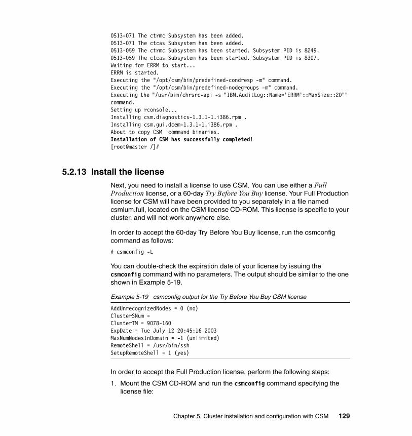
0513-071 The ctrmc Subsystem has been added.0513-071 The ctcas Subsystem has been added.0513-059 The ctrmc Subsystem has been started. Subsystem PID is 8249.0513-059 The ctcas Subsystem has been started. Subsystem PID is 8307.Waiting for ERRM to start...ERRM is started.Executing the "/opt/csm/bin/predefined-condresp -m" command.Executing the "/opt/csm/bin/predefined-nodegroups -m" command.Executing the "/usr/bin/chrsrc-api -s "IBM.AuditLog::Name='ERRM'::MaxSize::20"" command.Setting up rconsole...Installing csm.diagnostics-1.3.1-1.i386.rpm .Installing csm.gui.dcem-1.3.1-1.i386.rpm .About to copy CSM command binaries.Installation of CSM has successfully completed![root@master /]#
5.2.13 Install the licenseNext, you need to install a license to use CSM. You can use either a Full Production license, or a 60-day Try Before You Buy license. Your Full Production license for CSM will have been provided to you separately in a file named csmlum.full, located on the CSM license CD-ROM. This license is specific to your cluster, and will not work anywhere else.
In order to accept the 60-day Try Before You Buy license, run the csmconfig command as follows:
# csmconfig -L
You can double-check the expiration date of your license by issuing the csmconfig command with no parameters. The output should be similar to the one shown in Example 5-19.
Example 5-19 csmconfig output for the Try Before You Buy CSM license
AddUnrecognizedNodes = 0 (no)ClusterSNum = ClusterTM = 9078-160ExpDate = Tue July 12 20:45:16 2003MaxNumNodesInDomain = -1 (unlimited)RemoteShell = /usr/bin/sshSetupRemoteShell = 1 (yes)
In order to accept the Full Production license, perform the following steps:
1. Mount the CSM CD-ROM and run the csmconfig command specifying the license file:
Chapter 5. Cluster installation and configuration with CSM 129

# mount /mnt/cdrom# csmconfig -L /mnt/cdrom/csmlum.full
2. At the prompt, enter your language by choosing the appropriate number and pressing Enter.
3. Press Enter to view the license agreement.
4. Press 1 and Enter to accept the license agreement.
5. The csmconfig command returns an exit9 message when successful.
This completes the licensing of CSM, and you are now ready to verify the installation.
5.2.14 Verify the CSM installation on the management nodeTo verify that the management node was installed correctly, issue the following commands. The output should be similar to the following examples.
� The nodegrp command (the output is shown in Example 5-20)
Example 5-20 nodegrp command output
[root@master /]# nodegrpXseriesNodesKickstartNodesPreManagedNodesRedHat72NodesRedHatNodesLinuxNodesAllNodesRedHat73NodesManagedNodes[root@master /]#
� The lscondition command will list out the current condition information: the output is shown in Example 5-21.
Example 5-21 lscondition command output
[root@master /]# lsconditionDisplaying condition information:Name Node MonitorStatus"NodePowerStatus" "master.cluster.com" "Not monitored""NodeChanged" "master.cluster.com" "Monitored"
Note: Be sure to keep the license media you have been provided in a safe location. This media will be required if you have to reinstall CSM again in the future.
130 Linux Clustering with CSM and GPFS
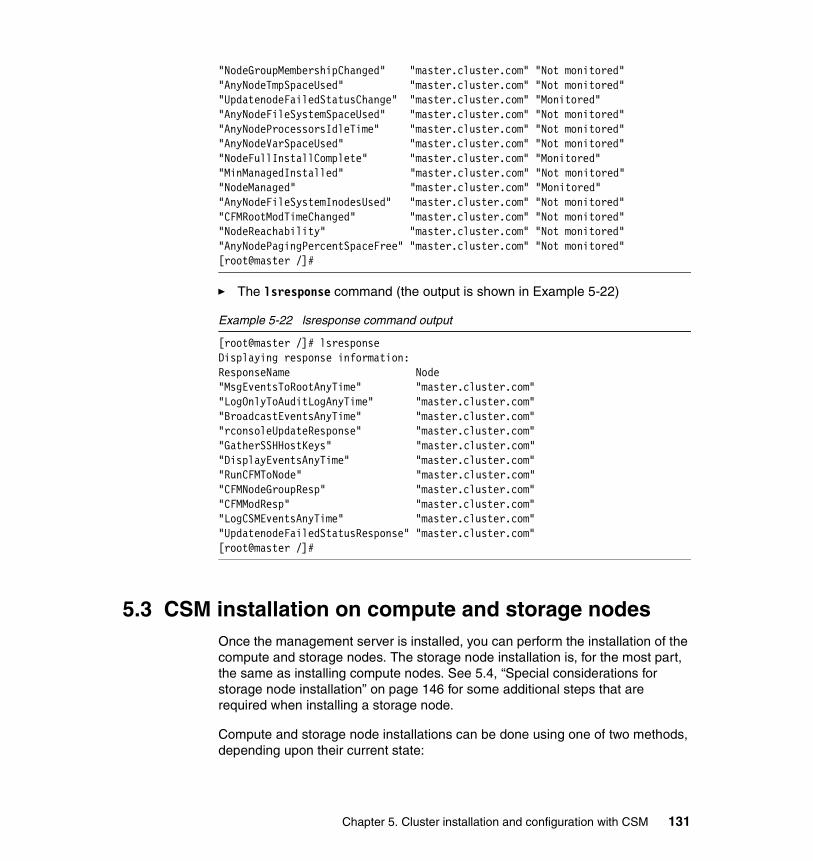
"NodeGroupMembershipChanged" "master.cluster.com" "Not monitored""AnyNodeTmpSpaceUsed" "master.cluster.com" "Not monitored""UpdatenodeFailedStatusChange" "master.cluster.com" "Monitored""AnyNodeFileSystemSpaceUsed" "master.cluster.com" "Not monitored""AnyNodeProcessorsIdleTime" "master.cluster.com" "Not monitored""AnyNodeVarSpaceUsed" "master.cluster.com" "Not monitored""NodeFullInstallComplete" "master.cluster.com" "Monitored""MinManagedInstalled" "master.cluster.com" "Not monitored""NodeManaged" "master.cluster.com" "Monitored""AnyNodeFileSystemInodesUsed" "master.cluster.com" "Not monitored""CFMRootModTimeChanged" "master.cluster.com" "Not monitored""NodeReachability" "master.cluster.com" "Not monitored""AnyNodePagingPercentSpaceFree" "master.cluster.com" "Not monitored"[root@master /]#
� The lsresponse command (the output is shown in Example 5-22)
Example 5-22 lsresponse command output
[root@master /]# lsresponseDisplaying response information:ResponseName Node"MsgEventsToRootAnyTime" "master.cluster.com""LogOnlyToAuditLogAnyTime" "master.cluster.com""BroadcastEventsAnyTime" "master.cluster.com""rconsoleUpdateResponse" "master.cluster.com""GatherSSHHostKeys" "master.cluster.com""DisplayEventsAnyTime" "master.cluster.com""RunCFMToNode" "master.cluster.com""CFMNodeGroupResp" "master.cluster.com""CFMModResp" "master.cluster.com""LogCSMEventsAnyTime" "master.cluster.com""UpdatenodeFailedStatusResponse" "master.cluster.com"[root@master /]#
5.3 CSM installation on compute and storage nodesOnce the management server is installed, you can perform the installation of the compute and storage nodes. The storage node installation is, for the most part, the same as installing compute nodes. See 5.4, “Special considerations for storage node installation” on page 146 for some additional steps that are required when installing a storage node.
Compute and storage node installations can be done using one of two methods, depending upon their current state:
Chapter 5. Cluster installation and configuration with CSM 131

� The first method, which will be discussed here, is the full installation. The KickStart install makes no assumptions about the state of the cluster node and performs a complete Linux and CSM installation. This is the appropriate method for a new compute or storage node or if you want to completely reinstall an existing node.
� The second method is the CSM only installation. In this case, the node already has Linux installed and we just want to install and configure CSM. An overview of this procedure can be found in Chapter 6, “Cluster management with CSM” on page 149.
The following is an overview of installing CSM on compute and storage nodes using the full installation method:
1. Configure the BIOS on the destination nodes.
2. Use the hostmap and nodedef files, and command line syntax to assemble all the node attributes.
3. Populate the CSM database with node attributes using the definenode command.
4. Verify the power method connectivity to all nodes
5. Optionally, customize the KickStart and firstboot templates
6. Prepare the management node to support installs by running the csmsetupks command.
7. Perform the compute and storage node installs using the installnode command.
8. Verify the success of the installation.
The following sections give the details of each one of the above steps.
5.3.1 BIOS settings for compute and storage nodesYou must set the boot order for each node in your cluster via the BIOS menu.
While the node is booting, press the F1 key when you are prompted to enter the BIOS menu. The boot order should be set as follows:
1. Diskette2. CD-ROM3. Network4. Hard disk 0
The “boot failed count” option should also be disabled. You also need to disable “boot sector virus detection” to prevent false virus indications during operating system installation.
132 Linux Clustering with CSM and GPFS

5.3.2 Preparing to run the definenode commandThe first step in installing nodes into the cluster is to define the nodes to the management node using the definenode command. This command populates the CSM database with the information required to install and manage the compute and storage nodes.
This information is in the form of node attributes that describe the nodes. These attributes are supplied to the definenode command in one of three ways:
� The first method is to use a host name mapping (hostmap) file. This is the recommended alternative if you have a large number of nodes to install.
� The second method is to use a node definition (nodedef) file. We recommend this option for smaller clusters.
� The third method is using the command line itself to enter the data. This method would be most useful for manipulating individual nodes and will be described in 5.3.3, “Running the definenode script” on page 136.
Additionally, the hostmap file may be used to generate a nodedef file. This is the procedure we will present here.
Several node attributes will have valid default values. However, those in Table 5-2 will need to be defined using hostmap, nodedef, and/or the definenode command, based on your specific cluster implementation.
Table 5-2 Node attribute definitions
Node attribute Definition
Hostname The name of the node being defined.
HWControlPoint Name of the device that controls the power for this node (that is, rsa001.cluster.com).
HWControlNodeId The host name of the node where the RSA card is installed in (that is, node1).
PowerMethod The type of power control being used (that is, xseries).
ConsoleMethod How to reach the serial console of this node (currently esp or mrv).
ConsoleServerName Name of the device that provides console connectivity (that is, esp001.cluster.com).
ConsoleServerNumber For daisy-chained terminal server devices, which device in the chain (starting at 1).
ConsolePortNum The port on the terminal server that connects to this node (in hex for ESP).
Chapter 5. Cluster installation and configuration with CSM 133

First method: Creating a host name mapping (hostmap) fileUse the lshwinfo command to create a hostmap file. For example, to create a hostmap file that lists the nodes associated with hardware control point rsa001.cluster.com and power method xseries to a file called /tmp/hostmap.txt, perform the following steps:
1. Issue the lshwinfo command as follows:
# lshwinfo -c mgrsa1.cluster.com -p xseries -o /tmp/hostmap.txt
The /tmp/hostmap.txt output file would look something like Example 5-23.
Example 5-23 lshwinfo output
[root@master root]# cat /tmp/hostmap.txt# Hostname::PowerMethod::HWControlPoint::NodeId::LParId::HWType::HWModel::HWSerialNumno_hostname::xseries::mgrsa1.cluster.com::node1::::::::no_hostname::xseries::mgrsa1.cluster.com::node2::::::::no_hostname::xseries::mgrsa1.cluster.com::node3::::::::no_hostname::xseries::mgrsa1.cluster.com::node4::::::::[root@master root]#
2. Edit the /tmp/hostmap.txt file to replace the no_hostname references with the correct host names for each node.
Example 5-24 edited lshwinfo output
# Hostname::PowerMethod::HWControlPoint::NodeId::LParId::HWType::HWModel::HWSerialNumnode1.cluster.com::xseries::mgrsa1.cluster.com::node1::::::::node2.cluster.com::xseries::mgrsa1.cluster.com::node2::::::::node3.cluster.com::xseries::mgrsa1.cluster.com::node3::::::::node4.cluster.com::xseries::mgrsa1.cluster.com::node4::::::::
As you can see in Example 5-24, the following attributes are defined in the hostmap file:
� Hostname� HWControlPoint
InstallMethod Sets KickStart for this procedure.
Node attribute Definition
Note: If you see a line where the fourth column in the lshwinfo output is a serial number instead of a host name, the ASM service processor ID has not been set correctly. See 5.2.8, “System Management hardware configuration” on page 122 for instructions on how to repair this. Then you can rerun the lshwinfo command to build a corrected hostmap file.
134 Linux Clustering with CSM and GPFS

� HWControleNodeId� PowerMethod
However, the following node attributes have not been defined:
� ConsoleMethod� ConsoleServerName� ConsoleServerNumber� ConsolePortNum� InstallMethod
These attributes will need to be later specified on the definenode command line. Optionally, you can use the hostmap file to create a nodedef file, where these values can be manually input.
Second method: Creating a node definition (nodedef) file
The nodedef file allows you more fine-grained control of the node attributes. It is best to work from the sample provided with the CSM software, which is located in /opt/csm/install/nodedef.sample. You can also generate a nodedef file from a hostmap file using the following command:
# definenode -M hostmap_file -s > nodedef_file
where hostmap_file and nodedef_file represents the name of the hostmap and nodedef files. For example:
# definenode -M /tmp/hostmap.txt -s > /tmp/nodedef.txt
Note that attributes that are common across all nodes can be placed the default stanza in your nodedef file. If an attribute appears in both the default stanza and the node definition itself, the node definition will take precedence.
Example 5-25 is the nodedef file used in our lab environment.
Example 5-25 Sample nodedef file
default: ManagementServer=master.cluster.com HWControlPoint=mgrsa1.cluster.com PowerMethod=xseries
ConsoleSerialDevice=ttyS0 ConsoleMethod=esp ConsoleServerName=mgesp1.cluster.com ConsoleServerNumber=1 InstallOSName=Linux
Tip: The second method is also the recommended method of defining nodes.
Chapter 5. Cluster installation and configuration with CSM 135

InstallCSMVersion=1.3.1 InstallMethod=kickstart InstallDistributionVersion=7.3node1.cluster.com: HWControlNodeId=node1 ConsolePortNum=0node2.cluster.com: HWControlNodeId=node2 ConsolePortNum=1node3.cluster.com: HWControlNodeId=node3 ConsolePortNum=2node4.cluster.com: HWControlNodeId=node4 ConsolePortNum=3
By using a nodedef file, whether built from scratch or generated from a hostmap file, you can supply all of the necessary node attributes. This simplifies the usage of the definenode command considerably and provides a documented definition of your node configuration. The nodedef file can then be preserved and used in the future to reinstall CSM on the cluster using the same configuration.
5.3.3 Running the definenode scriptUsing some or all of the hostmap and nodedef options discussed above, you should now be ready to run the definenode command, which populates the CSM database with the node information.
The following three sections describe functionally equivalent solutions to define nodes in a cluster based on the examples we used in this chapter.
First Method: Defining nodes using the hostmap fileWhen creating the hostmap file, the following node attributes have not been defined and need to be specified with the definenode command:
� ConsoleMethod� ConsoleServerName� ConsoleServerNumber� ConsolePortNum� InstallMethod
In order to define the nodes using the hostmap file, issue the following command:
# definenode -M /tmp/hostmap.txt -C mgesp1:1:1:4 InstallMethod=kickstart ConsoleMethod=esp
136 Linux Clustering with CSM and GPFS

Second Method: Defining nodes using the nodedef fileOnce you have completed all the required parameters in the nodedef file, you can defined the nodes using the nodedef file by typing:
# definenode -f /tmp/nodedef.txt
Third Method: Using the definenode CLI optionsIf you are working with a single node or a small group of nodes, you may use the definenode command line to supply all of the node attributes. The necessary command line options are as follows:
� The first node (host name or IP address) is defined with the -n option.
� The number of adjoining nodes to define is specified with the -c option.
� The list of HWControlPoints is set with the -H option. The value should be entered as HwControlPoint:Count, where HWControlPoint is the device that controls power for the nodes, and Count specifies how many nodes are controlled by that device. Specify multiple HWControlPoints by separating them with commas.
� The list of ConsoleServers is defined by using the -C option. The value should be entered as ConsoleServerName:ConsoleServerNumber:ConsolePortNum:Count, where Count is the number of nodes accessed by the specified ConsoleServer. See Table 5-2 on page 133 for definitions of the remaining fields.
� Define the PowerMethod directly on the command line by adding PowerMethod=xseries to the end of your definenode command.
� Likewise, define the InstallMethod attribute the same way by adding InstallMethod=kickstart.
For example, in order to define node1, node2, node3, and node4 manually using the command line, run the definenode command as follows:
# definenode -n node1 -c 4 -H mgrsa1:4 -C mgesp1:1:0:4 PowerMethod=xseries InstallMethod=kickstart
The output will be similar to Example 5-26. This output is similar when running definenode using the nodedef and hostmap definition files.
Example 5-26 definenode output
Important: Using the command line options, you can only define contiguous nodes at one time. If you need to define nodes from node1 to node010 and node012 to node014, you have to run definenode twice or use a nodedef or hostmap file.
Chapter 5. Cluster installation and configuration with CSM 137

Defining CSM Nodes:Defining Node "node1.cluster.com"("172.20.3.1")Defining Node "node2.cluster.com"("172.20.3.2")Defining Node "node3.cluster.com"("172.20.3.3")Defining Node "node4.cluster.com"("172.20.3.4")
Upon successful completion of the definenode command, each new node should be placed into the PreManaged mode. This means the node has been defined to CSM but has not been installed and activated. All nodes in the PreManaged mode dynamically become members of the PreManagedNodes node group.
You can verify that all your nodes are set in the PreManagedNodes group using the lsnode -N PreManagedNodes command. Likewise, lsnode -N ManagedNodes will show all nodes that have completed CSM installation. The output of the command is shown in Example 5-27.
Example 5-27 lsnode -N PreManagedNodes
[root@master /]# lsnode -N PreManagedNodesnode4.cluster.comnode3.cluster.comnode2.cluster.comnode1.cluster.com[root@master /]#
Troubleshooting definenodeIf definenode hangs or fails, it is most often due to host name resolution problems, such as:
� You entered a node host name that does not exist.� You entered an incorrect HWControlPoint host name.� You entered an incorrect ConsoleServerName.
In most cases, if you think you entered a wrong definition for the nodes, you can remove them from the PreManagedList with the rmnode -P nodename command and try again.
5.3.4 Verify that rpower worksBefore continuing, be sure that the remote power command is functioning properly by typing:
# rpower -a query
The results should be something like Example 5-28.
138 Linux Clustering with CSM and GPFS

Example 5-28 rpower command output
[root@master root]# rpower -a querynode1.cluster.com onnode2.cluster.com onnode3.cluster.com offnode4.cluster.com on[root@master root]#
Do not proceed until this command is working properly; otherwise, the CSM installation scripts used later in the install procedure will fail when they are unable to power cycle the nodes.
5.3.5 Customize the KickStart template (optional)The next phase of the install uses the /opt/csm/install/kscfg.tmpl.RedHat.7.3 file as a template to generate a KickStart file for each node. You can easily modify it to add packages or modify options. Before changing this file, be sure to make a backup of the original file.
Modifying the KickStart template allows you to customize the following attributes for your compute and storage nodes:
� Partition configuration� Root password� Predefined users� Services and their configuration� Log message destination (that is, to the local node or to the management
node)
For example, we would recommend adding the stanza in Example 5-29 to your KickStart file after the Setup services section to automate NTP installation and configuration on all cluster nodes.
Example 5-29 Automate NTP installation using the KickStart template
## Set up an ntpd.conf file#echo "server $MGMTSVR_HOSTNAME driftfile /etc/ntp/drift" > /etc/ntp.conf## Set up a step-tickers file#echo “$MGMTSVR_IP” > /etc/ntp/step-tickers## Turn on NTP service#chkconfig --level 345 ntpd on
Chapter 5. Cluster installation and configuration with CSM 139

#
5.3.6 Running the csmsetupks scriptAt this point, all nodes should have been defined in the CSM database and are on PreMangedNode status. Any customizations to the KickStart template have been completed. The next step in the installation process is to run the csmsetupks script, which performs the following tasks:
� Copies the RPM from the Red Hat Linux media or an alternate directory.
� Starts DHCP, NFS, and TFTP daemons if they are not already running.
� Creates a /etc/dhcpd.conf file for the MAC address collection and for full installation of the nodes.
� Creates the files that are necessary for network boot in /tftpboot.
� Gets the MAC addresses of all specified nodes.
� Generates a KickStart configuration file for each node.
� Creates a firstboot script for each node.
The csmsetupks command accepts the following attribute values:
� Netmask=xxx.xxx.xxx.xxx
The network mask for the cluster VLAN, which is used to communicate between the compute nodes and the management node.
� Gateway=xxx.xxx.xxx.xxx
The IP address the compute nodes should use as their default gateway.
� Nameservers=xxx.xxx.xxx.xxx,yyy.yyy.yyy.yyy,
Specifies the IP addresses of the DNS name servers the compute nodes should use.
The csmsetupks command accepts the following command-line options:
Attention: The csmsetupks script uses the Netmask, Gateway, and Nameservers attributes to build the /etc/dhcpd.conf configuration file. If these attributes are not specified on the csmsetupks command line, the default gateway, netmask, and nameserver for the management node will be used. If your management node has a network connection to your internal network (Public VLAN), it is likely that these defaults are not appropriate for the compute nodes. This may cause the csmsetupks script to fail or the nodes to hang during installation.
140 Linux Clustering with CSM and GPFS

-n Used to specify a node instead of all PreManagedNodes that have an InstallMethod of kickstart (default).
-p Used to specify the directory that contains the Red Hat Linux RPM files.
-x In case you do not need to copy the Red Hat RPM files.
-v Verbose mode.
In order to prepare the cluster nodes for a KickStart installation, type the following command:
# csmsetupks -P Netmask=255.255.0.0 Gateway=172.20.0.1 Nameserver=172.20.0.1
Example 5-30 shows the output of this command.
Example 5-30 csmsetupks
[root@master /]# csmsetupks -P Netmask=255.255.0.0 Gateway=172.20.0.1 Nameserver=172.20.0.1Copying Red Hat Images from /mnt/cdrom.Insert Red Hat Linux 7.3 disk 1. Press Enter to continue.
Insert Red Hat Linux 7.3 disk 2. Press Enter to continue.
Insert Red Hat Linux 7.3 disk 3. Press Enter to continue.
Setting up PXE.Collecting MAC Addresses for nodes node4.cluster.comAttempting to use dsh to collect MAC addresses.Cannot run dsh on node "node1.cluster.com" Cannot run dsh on node "node2.cluster.com" Cannot run dsh on node "node3.cluster.com" Cannot run dsh on node "node4.cluster.com" Generating /etc/dhcpd.conf file for MAC address collection.Setting up MAC Address Collection.Creating the Ramdisk for MAC Address Collection.8602+0 records in8602+0 records outmke2fs 1.27 (8-Mar-2003)8602+0 records in8602+0 records out 66.6%Running getmacs for nodes node1.cluster.com node2.cluster.con node3.cluster.com node4.cluster.com
Chapter 5. Cluster installation and configuration with CSM 141

node1.cluster.com: 00:09:6B:63:27:41
node2.cluster.com: 00:02:55:67:57:CFnode3.cluster.com: 00:02:55:C6:59:FD
node4.cluster.com: 00:02:55:C6:5A:05Setting up KickStart.10684 blocksAdding nodes to /etc/dhcpd.conf file for KickStart install: node1.cluster.com node2.cluster.com node3.cluster.com node4.cluster.com.
The csmsetupks script first tries a dsh (using ssh) connection to gather the MAC addresses. If the nodes had been already installed before (in case you try to re-install the nodes or run the csmsetupks command again), then the MAC addresses are already added in the PreManagedNode database and csmsetupks does not attempt to get MAC addresses for those nodes.
All nodes where the MAC addresses were not collected using the database or with dsh are rebooted by csmsetupks, which will then connect to the nodes through the serial port and retrieve the MAC addresses.
If, for some reason, csmsetupks is unable to properly capture the MAC addresses from the nodes, you can use a command to manually record the address into the node configuration database. The MAC addresses for each node can be gathered by either one of these methods:
� Capture address as it is displayed when the node first boots
� Monitor /var/log/messages on the management node as you boot the node in question. The node will attempt to boot via DHCP, and the dhcpd daemon on the management node will log the attempt as a DHCPDISCOVER, including the MAC address.
Once you have obtained the MAC addresses of the nodes csmsetupks has failed to get, you should run the following command for each of those nodes:
# chnode -n <nodename> InstallAdapterMacaddr=<MACaddr>
where <nodename> and <MACaddr> is the host name and MAC address of the node you want to define.
Troubleshooting csmsetupksThe installation can hang during csmsetupks processing at different points.
If you run into a problem, the first thing to do is to restart the command with the -v option (verbose) and see if it helps you determine what has failed. If csmsetupks has already successfully copied the Red Hat Linux 7.3 RPMs to the
142 Linux Clustering with CSM and GPFS

/csminstall directory, you should use the -x option when retrying the command so the RPMs will not be copied again unnecessarily.
5.3.7 Running the installnode scriptAt this point, all the pre-installation work is now complete, and all that is left to do is run the installnode script, which will actually install Linux and CSM on the specified nodes.
To install the nodes, type:
# installnode -P
The -P argument tells installnode to install all nodes that are in PreManaged mode and whose InstallMethod is set to kickstart, as shown in Example 5-31.
Example 5-31 KickStart installnode
[root@master /]# installnode -PNodes to install:
node1.cluster.comnode2.cluster.com
node3.cluster.com node4.cluster.comRebooting Node for full install: node1.cluster.comRebooting Node for full install: node2.cluster.comRebooting Node for full install: node3.cluster.comRebooting Node for full install: node4.cluster.comStatus of nodes after the install:Node Status---------------------------------------------------------node1.cluster.com Rebooting and Installing Node.node2.cluster.com Rebooting and Installing Node.node3.cluster.com Rebooting and Installing Node.node4.cluster.com Rebooting and Installing Node.
[root@master /]#
Tip: If you forget to use the -x option when retrying the csmsetupks command, you can simply press Control-C when it prompts for the first Red Hat disc to be installed, and retry the command using -x.
Note: The installnode command will return to the prompt before all nodes have completed their installations. This is not an error.
Chapter 5. Cluster installation and configuration with CSM 143

Each node will reboot and run a KickStart install via NFS access to the management server. Then the node will again reboot and run the post-installation script, which will actually install the CSM software. While this script is finishing, it may take a few moments for the node to properly respond to cluster commands, such as dsh.
In order to follow the installation progress on each node, you can either run the rconsole -N PreManagedNodes command on an xterm window on the management node, or run the monitorinstall command to display a summary of the installation status. Example 5-32 shows a sequence of commands showing the installation progress of our cluster installation.
Example 5-32 monitorinstall output sequence
[root@master /]# monitorinstallNode Status---------------------------------------------------------node1.cluster.com Rebooting and Installing Node.node2.cluster.com Rebooting and Installing Node.node3.cluster.com Rebooting and Installing Node.node4.cluster.com Rebooting and Installing Node.
[root@master /]# monitorinstallNode Status---------------------------------------------------------node1.cluster.com Rebooting to hard disknode2.cluster.com Rebooting to hard disknode3.cluster.com Rebooting and Installing Node.node4.cluster.com Rebooting to hard disk
[root@master /]# monitorinstallNode Status---------------------------------------------------------node1.cluster.com Installednode2.cluster.com Rebooting to hard disknode3.cluster.com Starting makenode to install CSM RPMsnode4.cluster.com Starting makenode to install CSM RPMs
[root@master /]# monitorinstallNode Status---------------------------------------------------------node1.cluster.com Installednode2.cluster.com Installednode3.cluster.com Installednode4.cluster.com Installed
[root@master /]#
144 Linux Clustering with CSM and GPFS

Troubleshooting installnodeIf you run into trouble during the installnode process, you can check the log file generated by installnode command and the status log files generated for each node to help you determine what is wrong.
The installnode log file is /var/log/csm/installnode.log. This file contains all the output generated that you would see on your console if you started installnode with the -v option.
The nodes status files are located in the /tftpboot/status directory. To know where the installation stopped and what tasks have completed, you can view the files directly, or use the monitorinstall -l command to display all node status files.
Also, you may want to recheck your definenode command to be sure you entered all information correctly. A simple error like having a typographical error in the InstallMethod field will cause the installnode to be unable to restart the nodes.
5.3.8 Verifying compute and storage node installationThis section shows some basic commands to verify that the cluster is correctly installed.
� To verify all nodes are reachable via the network, type lsnode -p. Nodes that return a 1 are present and accounted for. The output is shown in Example 5-33.
Example 5-33 lsnode -p output
[root@master /]# lsnode -pnode1: 1node2: 1node3: 1node4: 1[root@master /]#
� Verify that dsh is working on all nodes by running the date command on all nodes. For example, with dsh -a date. The output is shown in Example 5-34.
Example 5-34 dsh -a date output
[root@master /]# dsh -a datenode1.cluster.com: Mon July 19 23:42:09 CST 2003node3.cluster.com: Mon July 19 23:42:09 CST 2003node2.cluster.com: Mon July 19 23:42:09 CST 2003node4.cluster.com: Mon July 19 23:42:09 CST 2003
� To verify the power status of all nodes, type rpower -a query. The output is shown in Example 5-35.
Chapter 5. Cluster installation and configuration with CSM 145

Example 5-35 rpower -a query output
[root@master /]# rpower -a querynode1.cluster.com onnode2.cluster.com onnode3.cluster.com onnode4.cluster.com on[root@master /]#
5.3.9 Configuring NTP on your compute and storage nodesIf you have not already configured NTP on your compute and storage nodes using KickStart, as demonstrated in 5.3.5, “Customize the KickStart template (optional)” on page 139, you’ll need to manually configure them now.
In order to manually configure the nodes, two files need to be created:
� /etc/ntp.conf� /etc/ntp/step-tickers
Example 5-36 shows the content of the /etc/ntp.conf file.
Example 5-36 /etc/ntp.conf for compute and storage nodes
server master.cluster.comdriftfile /etc/ntp/drift
Example 5-37 shows the content of the /etc/ntp/step-tickers file. It should be a single line containing the cluster VLAN IP address of your management node.
Example 5-37 /etc/ntp/step-tickers content
172.20.0.1
On each compute node, type the following commands to start the NTP service:
# service ntp start# chkconfig --level 345 ntp on
Now your compute nodes are fully installed.
5.4 Special considerations for storage node installationThe steps for installing the storage node are almost the same as the compute node installation. When installing the storage node, be sure to turn off any Fibre-attached storage before performing the installation. Otherwise, the node
146 Linux Clustering with CSM and GPFS

may fail to be installed correctly. The system may panic during boot up due to an invalid boot device.
The following additional steps are required for the storage node installation:
1. Modify the /etc/modules.conf file.
Once the Linux and CSM installation is complete, perform the following changes to /etc/modules.conf file to ensure proper boot order.
Move the scsi_hostadapter qla2x00 entry to the end of the scsi_hostadapter entries, and renumber the scsi_hostadapter lines appropriately (that is, first adapter is blank, then '1', '2', and so on.).
In addition, make sure the following line is added:
options scsi_mod max_scsi_luns=255
Example 5-38 shows the /etc/modules.conf file before and after the changes.
Example 5-38 /etc/modules.conf changes
The /etc/modules.conf file BEFORE the changes
alias eth0 eepro100alias scsi_hostadapter qla2x00alias scsi_hostadapter1 aic7xxxalias scsi_hostadapter2 ipsalias eth1 e1000alias parport_lowlevel parport_pcalias usb-controller usb-ohci
The /etc/modules.conf file AFTER the changes
alias eth0 eepro100alias scsi_hostadapter aic7xxx <<alias scsi_hostadapter1 ips <<alias scsi_hostadapter2 qla2x00 <<alias eth1 e1000alias parport_lowlevel parport_pcalias usb-controller usb-ohcioptions scsi_mod max_scsi_luns=255 <<
2. Install a new boot ramdisk to reflect the changes in /etc/modules.conf.
This can be achieved by using the following sequence of Linux commands:
# depmod -a# mv /boot/initrd-<KNLVER>.img /boot/initrd-<KNLVER>.img.old# mv /boot/initrd-<KNLVER>smp.img /boot/initrd-<KNLVER>smp.img.old# mkinitrd /boot/initrd-<KNLVER>.img <KNLVER>
Chapter 5. Cluster installation and configuration with CSM 147

# mkinitrd /boot/initrd-<KNLVER>smp.img <KNLVER>smp
where <KNLVER> is the Kernel version of the Linux running on the storage node. It may be found by using the uname -r command. Be sure to perform this for both the smp and uniprocessor versions of the kernel.
3. Turn on or reconnect the Fibre Channel-connected storage and reboot. You should then be able to see your external storage.
5.5 SummaryIn this chapter, we covered the installation of CSM 1.3.1 on an IBM Cluster 1350. We have covered the main commands to perform the installation and have discussed some general installation troubleshooting. However, this is not an exhaustive troubleshooting guide; if you need more information, refer to the IBM Cluster Systems Management for Linux: Planning and Installation Guide, SA22-7853, provided with your copy of CSM or the csm.READMEfile in /opt/csm/README on your system.
Important: If, for some reason, you are running the legacy LILO boot loader rather than the default (GRUB), you will need to run the lilo -v command after creating the new ramdisks. Otherwise, your system may fail to boot.
148 Linux Clustering with CSM and GPFS

Chapter 6. Cluster management with CSM
This chapter provides examples of how to use the facilities provided by CSM to manage a cluster; It builds on the information provided in the rest of this redbook.
The following topics are addressed:
� Cluster nodes maintenance
� Controlling nodes remotely
� Configuration File Manager (CFM)
� Software Maintenance System (SMS)
� Event Monitoring
� Cluster configuration backup
� CSM uninstallation
6
© Copyright IBM Corp. 2002, 2004 149

6.1 Changing the nodes in your clusterThrough the node database, CSM allows nodes to be easily added and removed from the IBM Cluster 1350. Here we outline the steps required when the nodes that make up your cluster need attention.
6.1.1 Replacing nodesIn the unlikely event of hardware failure on a node, components will obviously need to be replaced. According to the instructions you received with your cluster, report the fault to IBM. An IBM Customer Engineer should be despatched on-site to replace the failing components. If possible, you should ensure any important data is backed up before the engineer arrives. Here we provide some examples of situations and CSM administrative tasks that should be performed.
Hard disk replacement and/or node re-installationIf a hard disk has failed, the replacement will be entirely blank and therefore require a full node re-installation, including the Linux operating system and CSM.
Since only the disk was replaced, all the information in the CSM node database is still correct. The node may be installed by running the following commands:
# csmsetupks -n <node_hostname> -x# installnode <node_hostname>
The installnode command will reboot the node and then start a network install. More information on installing nodes may be found in 5.3, “CSM installation on compute and storage nodes” on page 131.
Entire node or mainboard replacementFor each node defined in the CSM database, CSM stores the service processor ID and MAC address of the first on-board Ethernet card. If the node’s mainboard was replaced (or the entire node swapped-out), both these values may have changed and must be updated in the CSM database.
150 Linux Clustering with CSM and GPFS

Setup node service processorThe node’s service processor ID is contained in the HWControlNodeId attribute in the CSM node database; the service processor ID on the node is commonly set to match the node host name. When the node is replaced, the service processor name may not be set correctly; by default, it matches the node’s serial number.
To determine whether the service processor ID is set correctly, use the lshwinfo command.
Example 6-1 shows a listing of all the nodes connected to RSA mgrsa1. One of the nodes is listed as no_hostname and has SN#5502654 in the NodeId column; this is the node that was replaced. If your replacement node was swapped from elsewhere, it may be that its NodeId has been changed from the default — you may need to inspect the lshwinfo output very closely to spot this. Alternatively, it may be that the replacement node has the correct NodeId already set, in which case you do not need to reset it.
Example 6-1 lshwinfo showing a replaced node on an RSA
[root@master /]# lsnode -a HWControlPoint node1node1: mgrsa1.cluster.com# lshwinfo -c mgrsa1.cluster.com -p xseries#Hostname::PowerMethod::HWControlPoint::NodeId::LParId::HWType::HWModel::HWSerialNummgrsa1.cluster.com::xseries::mgrsa1.cluster.com::mgrsa1::::::::no_hostname::xseries::mgrsa1.cluster.com::SN#5502654::::::::node2.cluster.com::xseries::mgrsa1.cluster.com::node2::::::::node3.cluster.com::xseries::mgrsa1.cluster.com::node3::::::::[root@master /]#
Although it is not absolutely required, we recommend that you set the service processor ID to match the node host name. The procedure for doing this can be
Tip: Automatic MAC address collection for the new node requires a reboot. To avoid problems with Linux, it is a good idea to leave the node switched off until the MAC has been collected. (Rpower will boot the nodes and collect this information on its own)
� The BladeCenter Management Modules do not currently allow Rpower to work properly, manual intervention may be necessary to collect the information from the HS20’s. In our test lab we found that the quickest way to collect the MAC addresses from a blade was to simply pull it out and copy the information from product stickers located on the bottom side of the blades.
Chapter 6. Cluster management with CSM 151

found in 5.2.8, “System Management hardware configuration” on page 122. To determine which RSA to login to, use a command similar to:
# lsnode -a HWControlPoint node1
Once the service processor has restarted you should see the no_hostname disappear from the lshwinfo output, as in Example 6-2.
Example 6-2 lshwinfo output after resetting the NodeID
[root@master /]# lsnode -a HWControlPoint node1node1: mgrsa1.cluster.com# lshwinfo -c mgrsa1.cluster.com -p xseries#Hostname::PowerMethod::HWControlPoint::NodeId::LParId::HWType::HWModel::HWSerialNummgrsa1.cluster.com::xseries::mgrsa1.cluster.com::mgrsa1::::::::node1.cluster.com::xseries::mgrsa1.cluster.com::node1::::::::node2.cluster.com::xseries::mgrsa1.cluster.com::node2::::::::node3.cluster.com::xseries::mgrsa1.cluster.com::node3::::::::[root@master /]#
If you do not want to change the service processor name, change the HardwareControlID attribute for the node so that it matches the NodeID in the output of lshwinfo. For example:
# chnode node1 HardwareControlNodeId=SN#5502654
If you have changed the dial-in user or password on the service processor from the default (not recommended), see Example 6-3 for an example of running systemid to save the user information that will allow CSM remote access to the node.
Example 6-3 Using systemid to store service processor login information
[root@master /]# systemid node1 USERIDPassword:Verifying, please re-enter password:systemid: Entry created.[root@master /]#
Confirm the hardware control is functioning correctly by querying the power status of the node, as in Example 6-4. Verify rpower returns the correct power status without error.
Example 6-4 Demonstrating correct power control function
[root@master /]# rpower -n node1 querynode1.cluster.com off
152 Linux Clustering with CSM and GPFS
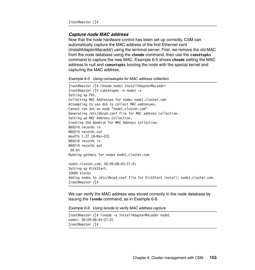
[root@master /]#
Capture node MAC addressNow that the node hardware control has been set up correctly, CSM can automatically capture the MAC address of the first Ethernet card (InstallAdapterMacaddr) using the terminal server. First, we remove the old MAC from the node database using the chnode command, then use the csmsetupks command to capture the new MAC. Example 6-5 shows chnode setting the MAC address to null and csmsetupks booting the node with the special kernel and capturing the MAC address.
Example 6-5 Using csmsetupks for MAC address collection
[root@master /]# chnode node1 InstallAdapterMacaddr=[root@master /]# csmsetupks -n node1 -xSetting up PXE.Collecting MAC Addresses for nodes node1.cluster.comAttempting to use dsh to collect MAC addresses.Cannot run dsh on node "node1.cluster.com"Generating /etc/dhcpd.conf file for MAC address collection.Setting up MAC Address Collection.Creating the Ramdisk for MAC Address Collection.8602+0 records in8602+0 records outmke2fs 1.27 (8-Mar-03)8602+0 records in8602+0 records out 66.6%Running getmacs for nodes node1.cluster.com
node1.cluster.com: 00:09:6B:63:27:41Setting up KickStart.10684 blocksAdding nodes to /etc/dhcpd.conf file for KickStart install: node1.cluster.com.[root@master /]#
We can verify the MAC address was stored correctly in the node database by issuing the lsnode command, as in Example 6-6.
Example 6-6 Using lsnode to verify MAC address capture
[root@master /]# lsnode -a InstallAdapterMacaddr node1node1: 00:09:6B:63:27:41[root@master /]#
Chapter 6. Cluster management with CSM 153

Boot or install LinuxIf the entire node was replaced, re-install the node using installnode, as for hard disk replacement. If the hard disks in the node still have Linux installed (they were swapped over or just not replaced), the node should only need a re-boot to come up into Linux correctly:
# rpower -n node1 reboot
6.1.2 Adding new nodes using the full installation processBefore you add new nodes into your CSM cluster you must decide which method you will use to add them. CSM supports adding the nodes via a fresh install (KickStart install) or by simply installing CSM onto a previously installed node (CSM only installation).
With a KickStart installation, the new node(s) will be network-installed as they were when you first obtained the cluster, via network boot and the RedHat KickStart install system. This will erase any data that may have been on the nodes before you installed this KickStart.
CSM only installation adds nodes to the cluster without a re-install; CSM uses ssh or rsh to log on to the node and install and configure the CSM components. This will not over-write or otherwise effect any existing OS on the nodes, though the nodes must be running a level of Linux supported by the target CSM release.
KickStart installation is the preferred method of adding nodes to a IBM Cluster 1350 or CSM cluster. It will leave the node(s) in a known state; the configuration differences that can occur when performing CSM only installs can cause significant problems.
This entire procedure has much in common with the original installation. You may want to refer to 5.3, “CSM installation on compute and storage nodes” on page 131 for more information.
Important: Although we discuss adding non xSeries nodes to a CSM cluster, this may not be supported, especially with a Cluster 1350. If you are in any doubt, you should contact the IBM Help Center for support and licensing guidance.
Important: When adding new xSeries nodes to your Cluster 1350, you must set up the BIOS as outlined in 5.3.1, “BIOS settings for compute and storage nodes” on page 132.
154 Linux Clustering with CSM and GPFS

Hardware and network setupBecause you are adding new nodes, you must allocate new IP addresses for them, perhaps on both cluster and IPC networks. You may also have added extra management hardware, which requires an IP address. You should allocate IP addresses before you start and ensure they are added in both /etc/hosts on the management node and your name server, as explained in 5.2.6, “Domain Name System (DNS) configuration” on page 114.
If you have added any additional hardware to the cluster to support the new nodes, you must configure it now. This includes RSAs (See 5.2.8, “System Management hardware configuration” on page 122), terminal servers (5.2.7, “Install Terminal Server” on page 114) and Ethernet switches.
When adding new xSeries nodes to your Cluster 1350, you must set up the BIOS and the service processor name. BIOS setup is outlined in 5.3.1, “BIOS settings for compute and storage nodes” on page 132 and service processor setup is explained in 5.2.8, “System Management hardware configuration” on page 122. If you have modified the service processor dial-in settings (we do not recommend this), you must also run systemid, as in Example 6-3 on page 152.
Defining new nodes into the clusterWhether you will be performing a KickStart or CSM only installation, you must first define the nodes in the node database.
Before you start, verify there are no nodes in the PreManagedNodes group by running nodegrp -p PreManagedNodes. The CSM commands we will be using include a -P switch to operate on the currently PreManaged nodes. If the group is currently empty, you can use the -P switch to refer only to the newly defined nodes. If there are existing nodes in the PreManagedNodes group, you may need to substitute -P in the commands below for -n <nodelist>, where <nodelist> is a list composed by the host names of the nodes to be added, for example, node1,node2,node3, or define a group and use -N.
We will be using lshwinfo to create a hostmap file, as described in “First method: Creating a host name mapping (hostmap) file” on page 134. This method will only work with IBM xSeries nodes; if you are adding different node-types, you will need to define the nodes using a nodedef file (see “Second method: Creating a node definition (nodedef) file” on page 135) or with the definenode command line.
lshwinfo will list all the nodes that are attached to one or more RSAs. If you supply it with the host names of any RSAs that have new nodes attached, you can create a hostmap suitable for passing to definenode. If there are existing
Chapter 6. Cluster management with CSM 155

nodes on the RSAs as well as new nodes, you may want to filter the output of lshwinfo for no_hostname:
# lshwinfo -c mgrsa1,mgrsa2 -p xseries | grep no_hostname > newnodes.map
Define the nodes into CSM using definenode. If you are adding a small number of nodes and are confident with the syntax of definenode, you can use the command line. The InstallMethod attribute should be set to kickstart for KickStart installs, but omitted for CSM only installation. For example:
# definenode -M newnode.map -C mgesp1:1:0:12 ConsoleMethod=esp \ PowerMethod=xseries InstallMethod=kickstart
If you are unsure of using definenode with hostmap files or you want to verify your settings, consider adding the -s switch. This will generate a nodedef file on stdout which can be redirected to a file and inspected and edited before passing it back to definenode -f as follows:
# definenode -s -M newnode.map -C mgesp1:1:0:12 ConsoleMethod=esp \ PowerMethod=xseries InstallMethod=kickstart > nodedef.new# vi nodedef.new# definenode -f nodedef.new
Installing the nodes using KickStartIf your new nodes have a console connection, csmsetupks can now be used to collect the MAC addresses. If you have added a small number of nodes, you can run the following:
# csmsetupks -P -x
If your nodes do not have a console connection, you will need to collect their MAC addresses manually. Boot the nodes one at a time and watch the syslog output. When the nodes send a DHCPDISCOVER packet, the dhcp server will log this to syslog and you can add it to the node database, as in Example 6-7.
Example 6-7 Using syslog to capture MAC addresses
[root@master /]# rpower -n node1 reset[root@master /]# tail -f /var/log/messages
Tip: During the course of our research for this redbook, we found information that might be useful, but that we were not able to verify in our test lab (due to power restrictions). If you have more than 20 nodes in your cluster this next bit of information might prove helpful.
� It is possible that if you have added more than 20 nodes, you will not be able to collect MACs or install in parallel. For ease of management, we recommend that you run csmsetupks and installnode for smaller groups of about 20 nodes at a time.
156 Linux Clustering with CSM and GPFS

July 15 10:37:36 master dhcpd: DHCPDISCOVER from 00:09:6B:63:27:41 via eth0July 15 10:37:36 master dhcpd: no free leases on subnet 172.20.0.0^C[root@master /]# chnode node1 InstallAdapterMacaddr=00:09:6B:63:27:41[root@master /]#
Once you have collected the MAC addresses of all the nodes, you must run csmsetupks as follows. If the MAC addresses are not already known, the nodes will not be rebooted:
# csmsetupks -P -x
Now that KickStart has been set up, the nodes can be installed. To install all PreManaged (newly added) nodes, run:
# installnode -P
As with csmsetupks, installnode should not be run for groups of more than 20 nodes at a time. Section 5.3.7, “Running the installnode script” on page 143 and onward contains information on verifying and troubleshooting node installation.
6.1.3 Adding new nodes using the CSM only installation processThe process of adding new nodes to a cluster using the CSM only installation process assumes, of course, that the operating system has already been installed. The first step is to gather and define all hardware and network information, as described in “Hardware and network setup” on page 155. Secondly, the node should be made known to CSM and defined into the CSM database. For this, refer to “Defining new nodes into the cluster” on page 155.
Before we jump into the CSM installation procedure itself, we need to perform additional pre-installation steps. When performing a CSM only install, dsh is used to send commands to the nodes for the actual installation. The underlying remote shell (ssh or rsh) must be able to access the node. You can test this by running:
# dsh -n <hostname> date
In the above example, dsh must display the time and date from the remote node without a password prompt. If you are asked for a password, you must configure your remote shell.
Note that the first time you connect to a new host using ssh, you will be prompted to confirm the authenticity of the host; this is normal and will only occur once, as in Example 6-8.
Example 6-8 Using ssh to a new node for the first time
[root@master /]# dsh -n node5.cluster.com date
Chapter 6. Cluster management with CSM 157

The authenticity of host 'node5.cluster.com (172.20.3.5)' can't be established.RSA key fingerprint is 77:4a:6c:22:17:88:e2:28:53:db:66:42:48:ec:33:6d.Are you sure you want to continue connecting (yes/no)? yesWarning: Permanently added 'node5.cluster.com,172.20.3.5' (RSA) to the list of known [email protected]'s password:Thu July 24 22:21:54 BST 2003[root@master /]# dsh -n node5.cluster.com dateThu July 24 22:21:55 BST 2003[root@master /]#
The DSH_REMOTE_CMD environment variable determines which remote shell dsh uses. Determine which remote shell is in use by running:
# echo $DSH_REMOTE_CMD
If DSH_REMOTE_CMD is un-set, the default is to use ssh.
Setting up sshTo configure ssh, add the contents of /root/.ssh/id_rsa.pub from the master to /root/.ssh/authorized_keys on the target node. You can copy and paste the file, but be careful; it’s one very long line that must not be broken up.
It may be easier to run the following command. This command will prompt you for a password:
# cat /root/.ssh/id_rsa.pub | ssh <hostname> ‘mkdir -p /root/.ssh;cat >> /root/.ssh/authorized_keys’
Setting up rshTo configure rsh, add the fully qualified cluster internal host name of the master node to /root/.rhosts on the target node. Note that the permissions on a .rhosts file must allow only root to read the file. This is all demonstrated in Example 6-9.
Example 6-9 Configuring remote rsh access
[root@master /]# cat >> /root/.rhostsmaster.cluster.com^D[root@master /]# chmod 600 /root/.rhosts[root@master /]# ls -l /root/.rhosts-rw------- 1 root root 23 July 15 14:23 .rhosts[root@master /]#
158 Linux Clustering with CSM and GPFS

Installing CSM on the nodesOnce dsh -n to the node works, install CSM on the node using the updatenode command, as shown in Example 6-10.
Example 6-10 Using updatenode to perform a CSM only installation
[root@master /]# lsnode -a Mode node1node1:PreManaged[root@master /]# updatenode node1node1.cluster.com: Setting Management Server to master.cluster.com.node1.cluster.com: Creating the Autoupdate provides database. This could take a few minutes.node1.cluster.com: Updating RPMsnode1.cluster.com: Node Install - Successful.[root@master /]# lsnode -a Mode node1node1:Managed[root@master /]# lsnode -p node1node1:1
As you can see in Example 6-10, when the node has been installed successfully, its mode should change from PreManaged to Managed.
6.1.4 Removing nodesRemoving nodes from the CSM cluster is accomplished using the rmnode command. Single nodes may be deleted by listing them on the command line or groups of nodes may be deleted using the -N switch. Normally, rmnode simply de-configures CSM on the target node(s) and then removes them from the CSM nodes database. The -u switch will also uninstall the CSM RPMs (but not any non-IBM pre-requisites), as in Example 6-11.
Example 6-11 Uninstalling nodes with rmnode -u
[root@master /]# rmnode -u node3node3.cluster.com: Uninstalling CSM ...node3.cluster.com: rmnode.client: Cannot erase rpm package csm.director.agent.Did not uninstall the Open Source prerequisites.The remote shell (SSH or RSH) have not been unconfigured on the Managed Nodes. To ensure security, you should unconfigure the remote shell on the nodes manually.[root@master /]#
Do not worry about the csm.director.agent error message; it is probably not installed.
Chapter 6. Cluster management with CSM 159

6.1.5 Changing host names of nodesIf you need to change any host names within the cluster, you must update the CSM nodes database and then the CSM configuration on the nodes.
Before you change any host names on the cluster, you should update /etc/hosts and the name server with the new names and/or addresses.
If you have changed the host name of a single node, run the following sequence of commands on the management node:
# chnode <oldhostname> Hostname=<newhostname># updatenode -k <newhostname>
The updatenode command will re-sync the CSM information on that node.
If you have changed the host name of the management node, then run the following sequence of commands on the management node:
# chnode -a ManagementServer=<newhostname># updatenode -a -k
Here, the updatenode command will re-configure all the nodes in the cluster with the new management node hostname.
6.2 Remote controlling nodesThe IBM Cluster 1350 is designed as a fully remote manageable solution. The combination of management components mean that physical access is seldom, if ever, required to the system. In this section, we outline some of these capabilities.
Note: If GPFS is installed on the nodes, uninstallation of SRC and RSCT RPMs will fail. These should be removed manually when GPFS is uninstalled.
Important: When changing host names, you must ensure that the management node still has remote shell (ssh or rsh) access to the nodes. You may need to edit /root/.rhosts on all the nodes and/or edit the host names in /root/.ssh/known_hosts on the management node. Test dsh -n before attempting to run the updatenode command.
160 Linux Clustering with CSM and GPFS

6.2.1 Power controlThe onboard service processors on the xSeries nodes control the mainboard power. Via the RSA, nodes may be powered on, off, and reset from the management node.
To check the current status of all the nodes in the cluster, use the query argument to rpower, as in Example 6-12.
Example 6-12 Using rpower to query the power status of all nodes in the cluster
[root@master /]# rpower -a querystorage1.cluster.com onnode1.cluster.com onnode2.cluster.com onnode3.cluster.com offnode4.cluster.com on[root@master /]#
Normally nodes are rebooted using the reboot or shutdown commands (usually run via dsh). If a node locks up completely and you want to press the reset switch on the front panel, use the reboot option of rpower instead; it has an identical effect.
To reset node4, use:
# rpower -n node4 reboot
Similarly, as shown in Example 6-13, nodes may be powered on or off using rpower.
Example 6-13 Power controlling nodes with rpower
[root@master /]# rpower -n node4 offnode4.cluster.com off complete rc=0[root@master /]# rpower -n node4 onnode4.cluster.com on complete rc=0
If rpower returns errors, it could be because the IBM.HWCTRLRM daemon has crashed. In order to restart HWCTRLRM, run:
# stopsrc -s IBM.HWCTRLRM# startsrc -s IBM.HWCTRLRM
If rpower fails for all the nodes on a particular RSA, it could be that the RSA has locked up and needs restarting. rpower may be used to restart hardware control points. To restart the RSA that controls node1, use:
# rpower -n node1 resetsp_hcp
Chapter 6. Cluster management with CSM 161

If this fails, use a Web browser on the management node to log in to the RSA and restart it. Some information on this can be found in 5.2.8, “System Management hardware configuration” on page 122.
6.2.2 Console accessIt is possible to access the node’s consoles via the terminal server(s). Console access is most commonly required when the network interface is accidentally configured incorrectly or in the case of boot-time problems. Beside the usual serial console support (accessing a LILO or GRUB prompt, watching boot messages, and getting a login prompt), the x335s support watching the BIOS boot screen accessing BIOS setup over the serial port.
Console access is significantly slower than the cluster network (9600 baud) and so is generally used only when the network is unavailable or unsuitable. Normal access to the nodes is over the cluster network via ssh, rlogin, and so on.
If you are running in X Windows, you can access the console of a particular node with:
# rconsole -n <hostname>
This will start the console in a new terminal on the current display.
If you are logged into the management server remotely (via ssh, for example) and want to use the current window to display the console, add the -t switch, as in Example 6-14. Note that you may need to press Enter before the login prompt appears.
Example 6-14 Remote console access with rconsole
[root@master eqnx]# rconsole -t -n node1[Enter `^Ec?' for help]Connected.
Red Hat Linux release 7.3 (Valhalla)Kernel 2.4.18-10smp on an i686
node1 login: [disconnect]
To exit from the console, use ^Ec. (Ctrl-E, then c, then a period).
From X Windows, the rconsole command can also be used to monitor a number of nodes. This is particularly useful when installing multiple nodes. Running
# rconsole -a
162 Linux Clustering with CSM and GPFS

will open a tiny terminal for each node in the cluster. Although these terminals are too small to read any details, they may be used to get an idea of what is happening. If the install bars stop moving or the kernel messages appear irregular, the window may be changed to full-size by holding down Ctrl, right-clicking on the window, and selecting Medium from the menu.
6.2.3 Node availability monitorCSM continually monitors the reachability of the nodes in the cluster via RSCT. Example 6-15 shows the use of lsnode to display this information.
Example 6-15 Checking node availability using lsnode
[root@master /]# lsnode -pnode1: 1node2: 1node3: 1node4: 1storage1: 1[root@master /]#
A value of 1 indicates the node is up and the RMC daemons are communicating correctly; a value 0 indicates the node is down. An error is denoted by the value 127.
This output format is the same as dsh. dshbak may be used to group up and down nodes, as in Example 6-16.
Example 6-16 Using dshbak to format lsnode output
[root@master /]# lsnode -p | dshbak -cHOSTS -------------------------------------------------------------------------node1, node2, node3, storage1------------------------------------------------------------------------------- 1
HOSTS -------------------------------------------------------------------------node4------------------------------------------------------------------------------- 0[root@master /]#
Chapter 6. Cluster management with CSM 163

Occasionally, lsnode -p may report a node as 127. This value is used in CSM to represent "unknown" and is an error condition. It can be caused by a number of factors:
� Newly defined node
Any node that is defined but has not yet had its OS or CSM correctly installed will show up as unknown. Run:
# nodegrp -p PreManaged
Any nodes listed have not yet had CSM installed and therefore will show as 127 until they have been installed.
� Temporary RMC failure
Occasionally, the RMC subsystem on the management node will lose contact with the node, causing this error. Restarting RMC on the node will solve this problem:
# dsh -w <hostname> /usr/sbin/rsct/bin/rmcctrl -z# dsh -w <hostname> /usr/sbin/rsct/bin/rmcctrl -s
� RMC configuration missing or incorrect
If the CSM configuration on the node is inconsistent, for example, if CSM was re-installed on the management node, RMC will not be able to negotiate correctly with the node. Refresh the node with updatenode:
# updatenode -k <hostname>
6.2.4 Hardware status and managementThe onboard service processors on the cluster nodes monitor various physical aspects of the node, such as fan speed and temperatures. These can be queried, via the RSAs, using the lshwstat command.
For example, Example 6-17 shows the use of lshwstat command to view the temperatures on node1.
Example 6-17 Querying a node temperature using lshwstat
[root@master /]# lshwstat -n node1 tempnode1.cluster.com:CPU 1 Temperature = 39.0 (102.2 F)Hard Shutdown: 95.0 (203 F)Soft Shutdown: 90.0 (194 F)Warning: 85.0 (185 F)Warning Reset: 78.0 (172.4 F)CPU 2 Temperature = 39.0 (102.2 F)Hard Shutdown: 95.0 (203 F)Soft Shutdown: 90.0 (194 F)
164 Linux Clustering with CSM and GPFS

Warning: 85.0 (185 F)Warning Reset: 78.0 (172.4 F)DASD 1 Temperature = 29.0 (84.2 F)Ambient Temperature = 25.0 (77F)[root@master /]#
The lshwstat command can be use used to query many aspects of an individual node or node groups, although querying a large number of nodes can be slow. Besides monitoring the health of the system, lshwstat can be used to query the hardware configuration of the nodes. lshwstat -h gives a complete list of all the options that may be queried, as shown in Example 6-18.
Example 6-18 lshwstat -h output
[root@master /]# lshwstat -hUsage: lshwstat -h lshwstat [-v] { -a | -n hostname[,hostname...] -N nodegroup[,nodegroup...] } { cputemp | disktemp | ambtemp | temp voltage | fanspeed | power | powertime reboots | state | cpuspeed | maxdimm | insdimm | memory | model | serialnum | asset | all }
-a runs the command on all the nodes in the cluster. -h writes usage information to standard output. -n hostname[,hostname...] specifies a node or list of nodes. -N nodegroup[,nodegroup...] specifies one or more nodegroups. -v verbose output.
cputemp -- reports CPU temperatures disktemp -- reports DASD temperatures ambtemp -- reports system ambient temperature temp -- reports all the above temperatures voltage -- reports VRM and system board voltages fanspeed -- reports percent of maximum fan is rotating power -- reports current power status powertime -- reports number of hours running since last reboot reboots -- reports number of system restarts state -- reports current system status cpuspeed -- reports speed of CPUs in MHz maxdimm -- reports maximum supported DIMMs insdimm -- reports number of installed DIMMs memory -- reports total system memory in MB model -- reports model type serialnum -- reports model serial number
Chapter 6. Cluster management with CSM 165

asset -- reports service processor asset tag all -- reports all the above information[root@master /]#
6.3 Node groupsCSM allows nodes to be grouped either by a host name list or via dynamic selection criteria based on node attributes.
In Example 6-19 we define a new group, TestGroup, containing the first three nodes of our cluster. We use nodegrp -a (add nodes to a group) to create the group. We then display (print) the contents of that group using nodegrp -p.
Example 6-19 Creating and displaying a new nodegroup with nodegrp
[root@master /]# nodegrp -a node1,node2,node3 TestGroup[root@master /]# nodegrp -p TestGroupnode1.cluster.comnode2.cluster.comnode3.cluster.com[root@master /]#
Individual nodes may be subsequently removed from a group using nodegrp -x, as shown in Example 6-20.
Example 6-20 Removing nodes from a group using nodegrp -x
[root@master /]# nodegrp -x node2 TestGroup[root@master /]# nodegrp -p TestGroupnode1.cluster.comnode3.cluster.com[root@master /]#
Dynamic groups are created by defining a select statement or "where" clause. Example 6-21 shows the creation of a dynamic group consisting of all the nodes managed via mgrsa1.
Example 6-21 Creating a dynamic group with nodegrp -w
[root@master /]# nodegrp -w "HWControlPoint=='mgrsa1.cluster.com'" RSA1Nodes[root@master /]# nodegrp -p RSA1Nodesnode1.cluster.comnode2.cluster.comnode3.cluster.comnode4.cluster.com
166 Linux Clustering with CSM and GPFS

[root@master /]#
The select clause of dynamic groups my be displayed using the "-W" switch. Example 6-22 shows the select clause of the predefined node group RedHat73Nodes.
Example 6-22 Displaying the select clause of a dynamic group using nodegrp -W
[root@master /]# nodegrp -W RedHat73NodesInstallDistributionName=='RedHat' && InstallDistributionVersion=='7.3'[root@master /]#
Both static and dynamic groups are removed using -D. Groups must be removed one at a time:
# nodegrp -D TestGroup# nodegrp -D RSA1Nodes
If any predefined nodegroups are accidentally removed or modified, they may be restored with predefined-nodegroups. Using the -f switch, all the predefined groups (AllNodes, ManagedNodes, and so on) will be initialized to their default setting:
# predefined-nodegroups -f
This will not affect any user created groups, whether static or dynamic.
6.4 Running commands on the nodesWhen working on a cluster, the administrator usually wants to run the same command across a number of nodes, often the entire cluster. CSM provides two ways of doing this; a simple command-line tool, dsh, and a Java GUI, DCEM.
6.4.1 Distributed shell (dsh)The dsh utility is a lightweight command-line tool that allows parallel commands to be easily issued from the terminal.
Example 6-23 shows the use of the date command with dsh to find out the time on all the machines in the cluster.
Example 6-23 Displaying the time on all nodes in the cluster using dsh
[root@master /]# dsh -a datenode4.cluster.com: Wed July 9 18:10:04 CDT 2003node3.cluster.com: Wed July 9 18:10:04 CDT 2003
Chapter 6. Cluster management with CSM 167

storage1.cluster.com: Wed July 9 18:10:04 CDT 2003node1.cluster.com: Wed July 9 18:10:04 CDT 2003node2.cluster.com: Wed July 9 18:10:04 CDT 2003[root@master /]#
Note that the answer does not come back in any particular order. Example 6-24 shows how the sort command can be used to format the output of dsh into node order.
Example 6-24 Formatting dsh output with sort
[root@master /]# dsh -a date | sortnode1.cluster.com: Wed July 9 18:10:44 CDT 2003node2.cluster.com: Wed July 9 18:10:44 CDT 2003node3.cluster.com: Wed July 9 18:10:44 CDT 2003node4.cluster.com: Wed July 9 18:10:44 CDT 2003storage1.cluster.com: Wed July 9 18:10:44 CDT 2003[root@master /]#
Often, it is more useful to see which nodes return similar or different values. CSM provides dshbak for this purpose.
Example 6-25 Using dshbak to format the output of dsh
[root@master /]# dsh -a date | dshbak -cHOSTS -------------------------------------------------------------------------node1.cluster.com, node2.cluster.com, node3.cluster.com, node4.cluster.com, storage1.cluster.com-------------------------------------------------------------------------------Wed July 9 18:11:26 CDT 2003[root@master /]#
In Example 6-25, all the nodes produced the same output. Example 6-26 shows what happened when the output differs.
Example 6-26 dsh and dshbak with different outputs
[root@master /]# dsh -a ls -l /tmp/file | dshbak -cHOSTS -------------------------------------------------------------------------node2.cluster.com, node3.cluster.com, node4.cluster.com, storage1.cluster.com--------------------------------------------------------------------------------rw-r--r-- 1 root root 0 July 9 18:17 /tmp/file
HOSTS -------------------------------------------------------------------------node1.cluster.com--------------------------------------------------------------------------------rw-r--r-- 1 root root 4 July 9 18:17 /tmp/file
168 Linux Clustering with CSM and GPFS

[root@master /]#
Note that in all the above examples, the piped commands (sort and dshbak) have run on the management node. Many shell meta-characters, including pipe (|), semicolon (;),and redirection (<, > and >>), must be enclosed within quotes if you want the operation to occur on the cluster nodes instead of locally on the management node. For example:
# dsh -av 'rpm -aq | grep glibc'
A commonly employed feature of dsh is the -v switch. This will verify (based on lsnode -p) the nodes availability before connecting. This saves waiting for the underlying remote shell (rsh or ssh) to timeout. Example 6-27 shows what happens when dsh -v is used and a node is not responding.
Example 6-27 dsh -v with a down node
[root@master /]# dsh -av datedsh: node4.cluster.com Host is not responding. No command will be issued to this hostnode1.cluster.com: Wed July 9 18:25:43 CDT 2003node2.cluster.com: Wed July 9 18:25:43 CDT 2003node3.cluster.com: Wed July 9 18:25:43 CDT 2003storage1.cluster.com: Wed July 9 18:25:43 CDT 2003[root@master /]#
It is possible that performing a large number of operations simultaneously could cause problems, for example, put excessive load on a file server. By default, dsh will attempt to run the specified commands in parallel on up to 64 nodes. This "fan-out" value may be changed by setting the DSH_FANOUT environment variable or using the -f switch to dsh:
# dsh -avf 16 rpm -i /nfs/*.rpm
6.4.2 Distributed command execution manager (DCEM)In contrast to the lightweight command line tool dsh, DCEM is a Java GUI that performs a similar task. DCEM allows you to construct command specifications for execution on multiple target machines, providing real-time status as commands are executed. You can enter the command definition, run-time
Tip: If you need to dsh a command that includes special characters but you are unsure how to quote them correctly, create a script file in a shared directory and use dsh to run the script file. Alternatively, DCEM does not suffer from the same special character problems (See 6.4.2, “Distributed command execution manager (DCEM)” on page 169).
Chapter 6. Cluster management with CSM 169

options, and selected hosts and groups for a command. You have the option of saving this command specification to use in the future. You can create and modify groups of hosts to use as targets for a command directly from DCEM.
Start DCEM from the command line by running:
# dcem
Figure 6-1 on page 170 shows all xosview windows from our four compute nodes on the GNOME desktop of our management node.
Figure 6-1 DCEM - xosview from all nodes
The logs are saved in /root/dcem/logs and the command in /root/dcem/scripts.
170 Linux Clustering with CSM and GPFS

Example 6-28 DCEM logs
TIME: July 19 23:42:58.581INFO: Command Name:xtermCommand: xterm -display master:0.0Successful Machines: node2.cluster.com node1.cluster.com node3.cluster.com node4.cluster.comFailed Machines:
TIME: July 19 23:44:01.444INFO: Command Name:gnome-termCommand: gnome-terminal -display master:0.0Successful Machines: node2.cluster.com node1.cluster.com node3.cluster.com node4.cluster.comFailed Machines:
TIME: July 19 23:45:45.385INFO: Command Name:nxtermCommand: nxterm -display master:0.0Successful Machines: node1.cluster.com node2.cluster.com node3.cluster.com node4.cluster.comFailed Machines:
For a complete description of the Distributed Command Execution Manager functions, refer to the IBM Cluster Systems Management for Linux: Administration Guide, SA22-7873.
6.5 Configuration File Manager (CFM)Configuration File Manager (CFM) provides a centralized way of managing configuration files within your CSM cluster. Files placed into /cfmroot on the management node will be copied out to the compute nodes, preserving permissions and ownership. By default, the files are copied out via a nightly cron job and placed in root’s crontab at CSM install. The administrator may elect to alter the time and/or frequency of this job, configure CSM to automatically copy any files out once they change, or disable automatic updates and only push the updates out manually.
Commonly, /etc/hosts should be identical on all the nodes within the cluster, including the management node. If the file in /etc is symlinked into /cfmroot/etc, it will be distributed out to all the nodes:
# ln -s /etc/hosts /cfmroot/etc/hosts
Chapter 6. Cluster management with CSM 171

Now you can copy /etc/hosts and any other files in /cfmroot to all the nodes:
# cfmupdatenode -a
If a file must be different on the nodes to the management node, it may be copied into /cfmroot. Files in /cfmroot are not propagated to the management node.
If a file should be copied to just a subset of nodes, create it with a _groupname extension. For example, to set up a file that will only be copied to those nodes in the MyrinetNodes group, run:
# cp /home/file /cfmroot/some/file._MyrinetNodes
CFM also supports pre- and post-installation scripts; these are particularly useful if you are replacing the configuration for a sub-system that needs to be shut down for the replacement to take place then re-started. Such scripts should be created with a .pre and .post extension and must be executable. Example 6-29 shows how we might use a .post script for /cfmroot/etc/ntp.conf.
Example 6-29 Creating a .post script for /cfmroot/etc/ntp.conf
[root@master /]# cd /cfmroot/etc[root@master etc]# cat > ntp.conf.post#!/bin/sh
/sbin/service ntp restart^D[root@master etc]# chmod 755 ntp.conf.post[root@master etc]#
ntp.conf.post will be automatically run if and when /etc/ntp.conf is replaced by CFM; it will not be run every time cfmupdatenode runs.
At CSM install time, an entry is created in root’s crontab that runs cfmupdatenode -a every night at midnight. If you desire periodic updates, this crontab may be edited to suit your requirements.
To configure CSM event monitoring so the files are automatically distributed whenever they are created or modified, run the following:
# startcondresp CFMRootModTimeChanged CFMModResp
Now, whenever a file in /cfmroot is updated, it will be updated on all the nodes in the cluster, within approximately five minutes. This is very convenient in smaller clusters, but can cause a performance impact on larger systems. If you have a large or production cluster and/or you will be updating /cfmroot often, it is not recommended that you use automatic updates.
172 Linux Clustering with CSM and GPFS

CFM will never delete files from the nodes; if you ever delete a file from /cfmroot, you must delete it from the nodes yourself, perhaps using dsh.
Note that /cfmroot physically stores data in /etc/opt/csm/cfmroot. If you have a small root (/) partition, you may need to place large files in another, larger file system and then symlink them into /cfmroot.
6.6 Software maintenance system (SMS)It is a very common task to install software on nodes in a cluster. CSM includes SMS, code that can be used to install or update RPMs on the nodes from the management node. SMS uses dsh from the management node to install RPMs from a directory that is NFS exported from the management node.
SMS can be used much like the rpm command, to add, remove and query packages from the Linux distribution media, across the cluster. For example, to install xcpustate from the CD set in /csminstall/Linux/RedHat/7.3/i386/RedHat, run:
# smsupdatenode -ai xcpustate-2.5-11.i386.rpm
xcpustate may be removed again with:
# smsupdatenode -ae --nodeps xcpustate
Non distribution packages may be placed in /csminstall/Linux/RedHat/7.3/i386/RedHat/updates and installed the same way; this is how we install the GPFS RPMs in 7.4.1, “Installing the source files” on page 205.
A further useful feature is the ability to automatically update any installed packages on the nodes. Copy any desired updates from RedHat to /csminstall/Linux/RedHat/7.3/i386/RedHat/updates and then run:
# smsupdatenode -a
This will apply fixes for packages that are already installed on the nodes but not install anything new.
Updates may be copied only to a subset of the nodes by a directory corresponding to that group. For example, updates placed in /csminstall/Linux/RedHat/7.3/i386/RedHat/updates/GpfsNodes will only be installed on nodes in the GpfsNodes group.
Chapter 6. Cluster management with CSM 173

6.7 Event monitoringCSM provides an extensible framework for detecting and responding to conditions arising on the cluster. The principle is that the administrator should not have to proactively monitor the status of a cluster; instead, the administrator should be notified in the event of any significant events.
The Resource Management and Control (RMC) subsystem is the scalable backbone of RSCT that provides a generalized framework for managing and monitoring resources.
RMC is comprehensively documented in IBM Reliable Scalable Cluster Technology for Linux: Guide and Reference, SA22-7892. For further detailed information, consult this book.
6.7.1 RMC componentsThe following components form the core of RMC:
� Resources� Sensors� Conditions� Responses
ResourcesA resource is a collection of attributes that describe or measure a logical or physical entity; all of RMC hinges on resources. Resources are introduced to RMC through resource managers, such as IBM.DMSRM and IBM.HWCTRLRM.
Resources may be queried using the lsrsrc command, as shown in Example 6-30. The CT_MANAGEMENT_SCOPE environment variable affects which resources lsrsrc will display. If it is un-set or set to 0 or 1, lsrsrc will display resources local to the current node. If lsrsrc is run on the management node with CT_MANAGEMENT_SCOPE set to 3, resources for all managed nodes will be displayed; this is the most common usage.
Example 6-30 Displaying node resources using lsrsrc
[root@master /]# export CT_MANAGEMENT_SCOPE=3[root@master /]# lsrsrc -Ab IBM.Host Name KernelVersionResource Persistent Attributes for: IBM.Hostresource 1: Name = "node2.cluster.com" KernelVersion = "2.4.18-3smp"resource 2: Name = "node1.cluster.com"
174 Linux Clustering with CSM and GPFS

KernelVersion = "2.4.18-3smp"resource 3: Name = "node3.cluster.com" KernelVersion = "2.4.18-3smp"resource 4: Name = "node4.cluster.com" KernelVersion = "2.4.18-3smp"resource 5: Name = "storage1.cluster.com" KernelVersion = "2.4.18-3smp"[root@master /]# unset CT_MANAGEMENT_SCOPE[root@master /]#
lsrsrc is extremely powerful. Consult the RMC documentation for more information on available resources.
SensorsSensors are a way of providing resources to RMC without writing a full-blown resource manager. An individual sensor measures a specific value, for example, the last time root logged into a system. The lssensor command can be used to display information about currently defined sensors, as in Example 6-31.
Example 6-31 Displaying sensor information with lssensor
[root@master /]# lssensorCFMRootModTime[root@master /]# lssensor CFMRootModTime Name = CFMRootModTime Command = /opt/csm/csmbin/mtime /cfmroot ConfigChanged = 0 Description = ErrorExitValue = 1 ExitValue = 0 Float32 = 0 Float64 = 0 Int32 = 0 Int64 = 0 NodeNameList = {master.cluster.com} RefreshInterval = 60 String = 1034278600 Uint32 = 0
Important: CT_MANAGEMENT_SCOPE should not be set when running the remainder of the commands in this section; they will return no information. The following command will unset this variable:
# unset CT_MANAGEMENT_SCOPE
Chapter 6. Cluster management with CSM 175

Uint64 = 0 UserName = root[root@master /]#
CFM uses the CFMRootModTime sensor to determine when the last file was modified in /cfmroot.
ConditionA condition determines, based on resources, if an event has occurred. For example, a file system condition may trigger when a file system reaches 95% full. A condition may also contain a re-arm condition, which must become true before any more events will be generated. The file system monitor could re-arm when the file system is less than 70% full.
The lscondition command will display currently defined conditions. Example 6-32 shows the pre-defined conditions and detail for the CFMRootModTimeChanged condition.
Example 6-32 Displaying condition information using lscondition
[root@master /]# lsconditionDisplaying condition information:Name Node MonitorStatus"NodePowerStatus" "master.cluster.com" "Not monitored""NodeChanged" "master.cluster.com" "Monitored""NodeGroupMembershipChanged" "master.cluster.com" "Not monitored""AnyNodeTmpSpaceUsed" "master.cluster.com" "Not monitored""UpdatenodeFailedStatusChange" "master.cluster.com" "Monitored""AnyNodeFileSystemSpaceUsed" "master.cluster.com" "Not monitored""AnyNodeProcessorsIdleTime" "master.cluster.com" "Not monitored""AnyNodeVarSpaceUsed" "master.cluster.com" "Not monitored""AnyNodeFileSystemInodesUsed" "master.cluster.com" "Not monitored""CFMRootModTimeChanged" "master.cluster.com" "Monitored""NodeReachability" "master.cluster.com" "Not monitored""AnyNodePagingPercentSpaceFree" "master.cluster.com" "Not monitored"
[root@master /]# lscondition CFMRootModTimeChangedDisplaying condition information:
condition 1: Name = "CFMRootModTimeChanged" Node = "master.cluster.com" MonitorStatus = "Monitored" ResourceClass = "IBM.Sensor" EventExpression = "String!=String@P" EventDescription = "An event will be generated whenever a file under /cfmroot is added or modified."
176 Linux Clustering with CSM and GPFS

RearmExpression = "" RearmDescription = "" SelectionString = "Name=\"CFMRootModTime\"" Severity = "i" NodeNames = {} MgtScope = "l"[root@master /]#
Note that the condition has English descriptions associated with it as a reminder for the function. A CFMRootModTimeChanged condition occurs whenever the CFMRootModTime sensor changes value.
ResponseThe action to perform when a condition event occurs. A response links to one or more scripts that will perform a certain action. It may be a very general alert or perform a more specific task. Responses may be associated with more than one condition.
Example 6-33 shows the predefined responses, which include sending e-mail to root, sending walls, and so on.
Example 6-33 Displaying condition responses using lsresponse
[root@master /]# lsresponseDisplaying response information:ResponseName Node"MsgEventsToRootAnyTime" "master.cluster.com""LogOnlyToAuditLogAnyTime" "master.cluster.com""BroadcastEventsAnyTime" "master.cluster.com""rconsoleUpdateResponse" "master.cluster.com""DisplayEventsAnyTime" "master.cluster.com""CFMNodeGroupResp" "master.cluster.com""CFMModResp" "master.cluster.com""LogCSMEventsAnyTime" "master.cluster.com""UpdatenodeFailedStatusResponse" "master.cluster.com"
[root@master /]# lsresponse CFMModRespDisplaying response information:
ResponseName = "CFMModResp" Node = "master.cluster.com" Action = "CFMModResp" DaysOfWeek = 1-7 TimeOfDay = 0000-2400 ActionScript = "/opt/csm/csmbin/CFMmodresp" ReturnCode = 0 CheckReturnCode = "n"
Chapter 6. Cluster management with CSM 177

EventType = "b" StandardOut = "n" EnvironmentVars = "" UndefRes = "n"[root@master /]#
As you can see, mostly the response is merely a notification. If possible, a response that actually solves the problem is usually more desirable; if /tmp fills up, you could clean old files from it. CFM uses CFMModResp to trigger the cfmupdatenode command.
6.7.2 Activating condition responsesJust defining a condition and response will not have any effect; the response must be associated with the condition for actual monitoring to occur.
To start monitoring a condition, use startcondresp. In Example 6-34, we set up a configuration so that root will get a message on the terminal when /var starts to fill up.
Example 6-34 Starting event monitoring with startcondresp
[root@master /]# startcondresp AnyNodeVarSpaceUsed MsgEventsToRootAnyTime[root@master /]# lscondresp AnyNodeVarSpaceUsedDisplaying condition with response information:
condition-response link 1: Condition = "AnyNodeVarSpaceUsed" Response = "MsgEventsToRootAnyTime" Node = "master.cluster.com" State = "Active"[root@master /]#
You may associate more than one response with a condition by specifying more than one response on the startcondresp command line or by running it multiple times. This can be useful if you want to both send an alert and perform an action in response to a condition.
6.7.3 Deactivating condition responsesCondition response associations may be temporarily de-activated using stopcondresp or permanently removed using rmcondresp. If multiple response associations to a condition are defined, they will all be stopped or removed unless an individual response is specified.
Example 6-35 shows the use of stopcondresp and rmcondresp.
178 Linux Clustering with CSM and GPFS

Example 6-35 Pausing and removing condition responses
[root@master /]# stopcondresp AnyNodeVarSpaceUsed MsgEventsToRootAnyTime[root@master /]# lscondrespDisplaying condition with response information:Condition Response Node State"UpdatenodeFailedStatusChange" "UpdatenodeFailedStatusResponse" "master.cluster.com" "Active""NodeChanged" "rconsoleUpdateResponse" "master.cluster.com" "Active""ViRunning" "BroadcastEventsAnyTime" "master.cluster.com" "Active""TmpNeedsCleaning" "BroadcastEventsAnyTime" "master.cluster.com" "Active""TmpNeedsCleaning" "CleanTmp" "master.cluster.com" "Active""AnyNodeVarSpaceUsed" "MsgEventsToRootAnyTime" "master.cluster.com" "Not active"[root@master /]# rmcondresp AnyNodeVarSpaceUsed[root@master /]#
6.7.4 Creating your own conditions and responsesHere we will provide a very brief overview of how to create your own conditions and responses. There is much more information on this subject in the IBM Reliable Scalable Cluster Technology for Linux: Guide and Reference, SA22-7892.
All resources provided by a resource manager feature static and dynamic attributes. Static attributes are constant for the particular instance of a resource, whereas dynamic attributes vary and may be monitored.
CSM includes a resource manager (IBM.FSRM) that provides a file system resource, IBM.FileSystem. In this example, we will utilize IBM.FileSystem to create a condition and response that monitor /tmp. If it starts to fill, we will automatically clean it out.
The static attributes of a FileSystem resource are those that do not change throughout the time the file system is mounted; for example, Dev represents the mounted device and MountDir represents where it is mounted. The dynamic attributes are those that can change; PercentTotUsed represents how full the file system is as a percentage. If the file system is unmounted and re-mounted elsewhere, the existing FileSystem resource will be destroyed and a new instance created.
Chapter 6. Cluster management with CSM 179

To list all the static attributes available on IBM.FileSystem resources, with examples for usage, run:
# lsrsrcdef -e IBM.FileSystem
List all the dynamic attributes, with examples, using:
# lsrsrcdef -e -A d IBM.FileSystem
You list all attributes of the currently available IBM.FileSystem resources with:
# lsrsrc -A b IBM.FileSystem
The CT_MANAGEMENT_SCOPE environment variable will affect which resources are listed. Unset, 0 or 1 will cause only resources on the local node to be listed. When CT_MANAGEMENT_SCOPE is set to 3, resources from the managed nodes will be listed. Remember to unset it before proceeding with the rest of this section.
In order to watch /tmp, we will be monitoring the PercentTotUsed attribute. Here we create a monitor called TmpNeedsCleaning that will monitor the IBM.Filesystem resource. It will look for an instance where the MountDir is /tmp and the PercentTotUsed (percentage of space used) is over 90. The condition will re-arm when the file system drops to 85% or less used. The command used is as follows:
# mkcondition -r IBM.FileSystem -s 'MountDir="/tmp"' -e 'PercentTotUsed>90' -E 'PercentTotUsed<=85’ -m m TmpNeedsCleaning
Note the -m m switch; this specifies the scope of the monitor. Scope m refers to the nodes being managed and is the same as a CT_MANAGEMENT_SCOPE of 3.
Now we need to create a response that will clean /tmp on the correct node. Let us assume that all the nodes have the fictitious script /usr/local/sbin/tmpscrubber installed that will clean all the old files from /tmp. In Example 6-36, we demonstrate a very basic response script. Note that the script will run on the management node but must clean /tmp on the correct node.
Example 6-36 Creating an event response script
[root@master /]# cat >> /usr/local/sbin/cleannodetmp#!/bin/sh
[ -z “$ERRM_NODE_NAME” ] && exit 1
# Use -n switch to rsh/ssh to prevent stdin being readdsh -o '-n' -n “$ERRM_NODE_NAME” /usr/local/sbin/tmpscrubber^D[root@master /]# chmod 755 /usr/local/sbin/cleannodetmp
180 Linux Clustering with CSM and GPFS
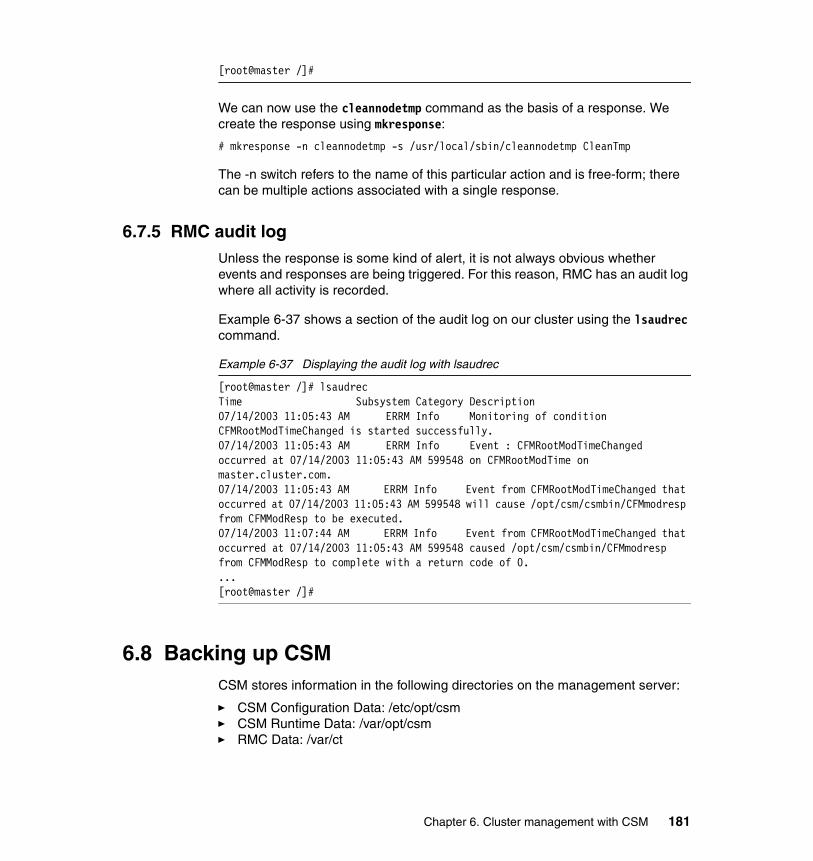
[root@master /]#
We can now use the cleannodetmp command as the basis of a response. We create the response using mkresponse:
# mkresponse -n cleannodetmp -s /usr/local/sbin/cleannodetmp CleanTmp
The -n switch refers to the name of this particular action and is free-form; there can be multiple actions associated with a single response.
6.7.5 RMC audit logUnless the response is some kind of alert, it is not always obvious whether events and responses are being triggered. For this reason, RMC has an audit log where all activity is recorded.
Example 6-37 shows a section of the audit log on our cluster using the lsaudrec command.
Example 6-37 Displaying the audit log with lsaudrec
[root@master /]# lsaudrecTime Subsystem Category Description07/14/2003 11:05:43 AM ERRM Info Monitoring of condition CFMRootModTimeChanged is started successfully.07/14/2003 11:05:43 AM ERRM Info Event : CFMRootModTimeChanged occurred at 07/14/2003 11:05:43 AM 599548 on CFMRootModTime on master.cluster.com.07/14/2003 11:05:43 AM ERRM Info Event from CFMRootModTimeChanged that occurred at 07/14/2003 11:05:43 AM 599548 will cause /opt/csm/csmbin/CFMmodresp from CFMModResp to be executed.07/14/2003 11:07:44 AM ERRM Info Event from CFMRootModTimeChanged that occurred at 07/14/2003 11:05:43 AM 599548 caused /opt/csm/csmbin/CFMmodresp from CFMModResp to complete with a return code of 0....[root@master /]#
6.8 Backing up CSMCSM stores information in the following directories on the management server:
� CSM Configuration Data: /etc/opt/csm� CSM Runtime Data: /var/opt/csm� RMC Data: /var/ct
Chapter 6. Cluster management with CSM 181

Additional user customizable files are located in /opt/csm/install. We recommend that these are backed up as well.
Note that by default, /cfmroot is a symlink to /etc/opt/csm/cfmroot. If you have a lot of data in /cfmroot, your CSM backup may be large.
In order to back up /var/ct, the RMC subsystems must be shutdown. The recommended procedure to back up the CSM configuration is to run the following on the management node:
1. Stop the RMC subsystems:
# /usr/sbin/rsct/bin/rmcctrl -z
2. Back up all CSM data related directories:
# tar -czvf csm-backup-20031119.tar.gz -C / etc/opt/csm var/opt/csm var/ct opt/csm/install
3. Restart the RMC subsystems:
# /usr/sbin/rsct/bin/rmcctrl -s
These files should be backed up periodically and after any significant change to the CSM configuration.
Additionally, you may choose to save a copy of your nodedef file to ease re-installation of CSM. If you did not save a nodedef file when you created the nodes, you can generate one from the CSM database by running:
# lsnode -F
6.9 Uninstalling CSMIf you want to completely remove CSM from all the nodes in your cluster and the management node, use the uninstallms command:
# uninstallms -u
This will:
� Remove the CSM code from the cluster nodes by running rmnode -u -N AllNodes.
� Uninstall CSM rpms from the management node.
� Delete the CSM logs from the management node.
The uninstallms -u command will not remove the CSM configuration from /etc/opt/csm, the CD images from /csminstall, or the csm.core fileset from the
182 Linux Clustering with CSM and GPFS

management node. These must all be uninstalled manually, as shown in Example 6-38.
Example 6-38 Uninstalling CSM
[root@master /]# uninstallms -uWARNING: The command will clean the nodes and remove all the nodes, node groups and uninstall Management Server.If you want to continue , press "y". Otherwise press Enter to quit.yDid not remove the directories or files /csminstall, /cfmroot.Did not Remove the Packages csm.core.Did not uninstall the Open Source prerequisites.The remote shell (SSH or RSH) have not been unconfigured on the Management Server. To ensure security, you should unconfigure the remote shell on the server manually.[root@master /]# rpm -e csm.core[root@master /]# rm -rf /etc/opt/csm /csmintall[root@master /]#
Chapter 6. Cluster management with CSM 183

184 Linux Clustering with CSM and GPFS

Chapter 7. GPFS installation and configuration
This chapter provides information on how to do the initial setup on the nodes for the GPFS installation and creation of the GPFS cluster, which includes:
� GPFS planning
� GPFS code installation
� GPFS cluster implementation
7
© Copyright IBM Corp. 2002, 2004 185

7.1 Basic steps to install GPFSThis section describes the basic steps for installing a GPFS cluster. The goal of this section is not to provide details of all the installation steps, but to give a quick overview of the installation process.
� Plan the installation
Before installing any software, it is important to plan the GPFS installation by choosing the hardware, deciding which kind of disk connectivity to use (direct attached or network attached disks), selecting the network capabilities (which depends a lot on the disk connectivity), and, maybe the most important, verifying that your application can take advantage of GPFS.
� Install the packages
At this point, the GPFS architecture has been defined and the machines have Linux installed (with or without the CSM product). It is time now to install the packages on all the nodes that will be part of the GPFS cluster.
� Create the GPFS cluster
Once the GPFS packages are installed on the nodes, you need to create the GPFS cluster. To create the GPFS cluster, we need a file that contains all of the node host names or IP addresses. Then we have to use the mmcrcluster command to create the cluster. This command will create cluster data information on all nodes chosen to be part of the GPFS cluster. In case a new node needs to be added to an already existing GPFS cluster, the mmaddcluster command can be used.
� Create the nodeset(s)
Now that GPFS knows which nodes are part of the cluster, we have to create the nodeset (a GPFS cluster can have multiple nodesets). The mmconfig command will be used to create a nodeset.
� Start GPFS
After the nodeset is created, you should start it before defining the disk. Use the mmstartup command to start the GPFS daemons.
� Disk definition
All disks used by GPFS in a nodeset have to be described in a file, and then this file has to be passed to the mmcrnsd command. This command gives a name to each described disk and ensures that all the nodes included in the nodeset are able to gain access to the disks with their new name.
186 Linux Clustering with CSM and GPFS

� Creating the file system
Once the cluster, the nodeset(s), and the disks have been defined, then it is time to create the file system. With GPFS, the mmcrfs command is used for that purpose.
There are many options that can be activated at this time, like file system auto-mounting, file system block size, data or metadata replication, and so on.
� Mounting the file system
At last, you have to mount the file system after it is being created. Once the file system had been mounted, it can be used by the nodes for read and write operations.
If you set auto-mounting option, your GPFS file system will be automatically mounted when the nodes reboot.
7.2 GPFS planningThe planning of a GPFS implementation is usually driven by four factors:
� The desired file system throughput and performance
� The desired service availability
� The availability and costs of storage and network hardware
� The GPFS file system size and replica
The best performance and file system availability can be achieved by using direct attached disks, while you can also have high availability of your disks using Network Shared Disks servers (NSD servers), with lower performance.
Direct attached configurations are feasible when the number of nodes in the nodeset is relatively small. When the number of nodes in the nodeset is greater than the number of nodes that can be simultaneously directly attached to the disks, you must use the Network Shared Disks (NSD), with disks defined in a primary and secondary servers.
You also have to define the size of your GPFS file system. The size of a GPFS file system depends on many factors, like block size and number of replicas. In an environment without any kind of replicas, the file system size can be about 95 to 99 percent of the capacity of the disks. If you activate full replication (data and metadata), you will end up with less then 50 percent of the capacity of the disks. See 4.2.5, “Data and metadata replication capability” on page 89 for more information.
Chapter 7. GPFS installation and configuration 187

7.2.1 Network implementationThe network utilization for the cluster is directly tied to the model of GPFS nodesets that will be used. In a NSD network attached model, all client nodes (all nodes that are not a primary server for some disk) will be using the network to gain access to the GPFS file systems. In a NSD direct attached model, the network will be used for metadata purposes only.
In NSD network attached model, the primary network should be at least Gigabit Ethernet running in full-duplex mode. The access to disk data through the network can easily saturate if you use a Fast Ethernet network. For better performance, Myrinet Technology should be considered.
You should also consider using a dedicated network segment for the nodes to communicate to each other instead of using only one network bus for everything. This is not a requirement, but can help to improve performance.
GPFS does not support IP aliases for the managed network adapters. You can use them, but do not use the aliases as references for the GPFS to communicate within the cluster.
7.2.2 DocumentationThe use of worksheets and drawings for documenting and planning the GPFS cluster installation and management is one of the keys for success. These worksheets can and will help you manage the disks, file systems, and nodes; hence, they must have enough information about all involved systems: Linux installation, network configuration, disk definition, file systems information, and information regarding the cluster itself.
Table 7-1 and Table 7-2 on page 189 are some examples of completed worksheets for a GPFS cluster.
Table 7-1 File system descriptions
File system Mount point NSDs Replicas
/dev/gpfs0 /gpfs0 gpfs1nsd;gpfs2nsd;gpfs3nsd
Data only
/dev/gpfs1 /gpfs1 gpfs4nsd;gpfs5nsd;gpfs6nsd
Metadata and data
/dev/gpfs2 /gpfs2 gpfs7nsd;gpfs8nsd;
Metadata only
188 Linux Clustering with CSM and GPFS

Table 7-2 NSD descriptions
7.3 Preparing the environmentThis section will provide information on how to prepare the environment to install GPFS software on the cluster nodes, getting them ready for GPFS customization and file system creation.
For the examples in this redbook, we will be using a six-nodes cluster. This cluster contains one management node, one storage node directly attached to storage enclosure, and four compute nodes named node001.cluster.com, node002.cluster.com, node003.cluster.com, and node004.cluster.com, referred to as node001, node002, node003, and node004. The operating system is Red Hat Linux 7.3 with kernel version 2.4.18-10smp.
7.3.1 Nodes preparationGPFS software comes as an option for IBM Cluster 1350. In this chapter, we assume that you have your IBM Cluster 1350 with CSM configured. We will take the advantage of CSM management tools such as cfmupdatenode, smsupdatenode, and dsh during GPFS installation. Refer to Chapter 6, “Cluster management with CSM” on page 149 for further information.
If you use the NSD network attached model for GPFS disk storage, you will need one storage attached server or so-called storage node. Refer to 5.4, “Special
Disk PVID NSD Holds D/M Primary server
Secondary server
C0A800E93BE1DAF6
gpfs1nsd D/M node1 node2
C0A800E93BE1DAF7
gpfs2nsd D/M node2 node1
C0A800E93BE1DAF8
gpfs3nsd D/M node3 node1
C0A800E93BFA7D86
gpfs4nsd D node1 node2
C0A800E93BFA7D87
gpfs5nsd D node2 node1
C0A800E93BFA7D88
gpfs6nsd D/M node3 node1
Chapter 7. GPFS installation and configuration 189

considerations for storage node installation” on page 146 on how to install the storage node.
7.3.2 Prerequisite softwareExample 7-3 describes some prerequisite software that needs to be installed prior to GPFS installation. It is necessary to verify that your nodes have at least the specified level of the prerequisite software described below installed on each node in the GPFS cluster; some of the software is already installed prior to CSM installation.
Table 7-3 Prerequisite software
7.3.3 Prepare kernel source file for GPFS and Myrinet adapterBecause GPFS code works at the kernel level (as kernel extensions), it highly depends on the kernel level to run properly. Therefore, you have to build your GPFS open source portability module before building a GPFS cluster, and a kernel source file is required for that. You may check the list of kernel versions that may be supported at the following site:
http://www-1.ibm.com/servers/eserver/clusters/software/gpfs_faq.html
Periodic updates of the portability layer to support additional kernel levels may be found at the following site:
http://oss.software.ibm.com/developerworks/projects/gpfs/
You also need the kernel source to build the Myrinet adapter driver.
Packages from Red Hat 7.3 CD-ROM Where to install
pdksh 5.2.14 In all nodes
gcc-c++-2.96-98 In the management node
libstdc++-devel-2.96-98 In the management node
gcc-2.96-98 In the management node
glibc-devel-2.2.5-34 In the management node
glibc-utils-2.2.5-34 In the management node
glibc-kernheaders-2.4-7.14 In the management node
cpp-2.96-98 In the management node
kernel-source-<your kernel version> In the management node
190 Linux Clustering with CSM and GPFS

This is a Red Hat Linux specific procedure to prepare the kernel:
1. The GPFS portability layer and Myrinet adapter source files set the Linux source directory to /usr/src/linux while the default directory in Red Hat is /usr/src/linux-<version>. Rather than changing both GPFS portability layer and Myrinet adapter source, we would suggest you make a symbolic link to linux-<version>. In our lab, we use kernel version 2.4.18-10smp, so our modification is as shown in Example 7-1.
Example 7-1 Symbolic link to the appropriate kernel
[root@masternode /]# cd /usr/src[root@masternode src]# ln –s linux-2.4.18-10smp linux [root@masternode src]#
2. Check the content of the VERSION, PATCHLEVEL, SUBLEVEL, AND EXTRAVERSION variables in the /usr/src/linux/Makefile file to match the release version of your kernel. Example 7-2 shows the content of these variables in our management server.
Example 7-2 Content of variables in /usr/src/linux/Makefile
VERSION = 2PATCHLEVEL = 4SUBLEVEL = 18EXTRAVERSION = -10smp
3. Copy the /usr/src/linux/configs/kernel-<version>.config file to /usr/src/linux/.config file and configure it, as shown in Example 7-3.
Example 7-3 Configuring the .config file
[root@masternode src]# cd /usr/src/linux[root@masternode linux]# cp configs/kernel-2.4.18-i686-smp.config .config[root@masternode linux]# make oldconfig[root@masternode linux]# make dep[root@masternode linux]#
7.3.4 Time synchronizationBecause all nodes will share the same disks and they will write on all disks and keep records of all activities, it is very important that all nodes have the same system time. This will assure file creation and modification time accuracy in the file system, as well as make it easier to cross-reference information between the nodes during trouble-shooting. We suggest that you use an Network Time Protocol (NTP) server for time synchronization within your GPFS cluster.
Chapter 7. GPFS installation and configuration 191

For information on how to install NTP, refer to 5.2.4, “NTP configuration” on page 111.
7.3.5 Setting the remote command environmentYou may choose whether to use rsh/rcp or ssh/scp for the cluster installation and management. The GPFS system will use these communication systems to install, configure, and manage the cluster. Considering that the nodes already have CSM configured and the default remote command for CSM is ssh and scp, we would recommend you use ssh and scp as well. The default remote command for GPFS is rsh and rcp. If you are going to use ssh and scp, you have to define them when you create the cluster. In our lab, we will use ssh and scp as our cluster remote command. Refer to “OpenSSH” on page 285 for information on how to customize SSH in the cluster.
SSH known hostsIn addition to SSH configuration, make sure that proper authorization is granted to all nodes in the GPFS cluster and the nodes in the GPFS cluster can communicate without the use of a password. If you use a Myrinet network, you have to modify /root/.ssh/known_hosts file in each nodes and add the Myrinet long and short network name and its IP address after each node name, so that SSH will treat them as its known hosts and not ask for password for every nodes. Example 7-4 shows the /root/.ssh/known_hosts file that we use in our SSH configuration.
Example 7-4 /root/.ssh/known_hosts file
masternode.cluster.com,masternode,10.0.0.1 ssh-rsa AAAAB3NzaC1yc2EAAAABIw...storage001.cluster.com,storage001,10.1.0.141,storage001-myri0.cluster.com,storage001-myri0,10.2.1.141 ssh-rsa AAAAB3NzaC1yc2EAAAABIwAAAIEAvC6Z4XyiZAdcCh3...node001.cluster.com,node001,10.0.3.1,node001-myri0.cluster.com,node001-myri0,10.2.1.1 ssh-rsa AAAAB3NzaC1yc2EAAAABIwAAAIEAzZSxfmnDP6LiO...node002.cluster.com,node002,10.0.3.2,node002-myri0.cluster.com,node002-myri0,10.2.1.2 ssh-rsa AAAAB3NzaC1yc2EAAAABIwAAAIEAv5/0Pr1pnpMkz...node003.cluster.com,node003,10.0.3.3,node003-myri0.cluster.com,node003-myri0,10.2.1.3 ssh-rsa AAAAB3NzaC1yc2EAAAABIwAAAIEAsemvouyg98eAV...node004.cluster.com,node004,10.0.3.4,node004-myri0.cluster.com,node004-myri0,10.2.1.4 ssh-rsa AAAAB3NzaC1yc2EAAAABIwAAAIEAvBuHkhGYmXpQ
To test whether we can go ahead with the GPFS code installation process, run the following test:
1. Log into node001 as root.
2. Connect to node001, node002, and node003 (through rsh or ssh).
3. From node002, connect to node001, node004, and node003.
192 Linux Clustering with CSM and GPFS

4. From node003, connect to node001, node002, and node004.
5. From node004, connect to node001, node002, and node003.
All connections should have completed without password prompting or any request for key confirmation.
7.3.6 Myrinet adapter installationMyrinet network comes as an option in IBM Cluster 1350. If you use Myrinet technology, you need to install Myrinet adapter on each nodes before beginning GPFS installation.
At the time this book is written, there is no RPM provided for this driver, so you need to configure, compile, and load the driver before installing GPFS. Because we will need to distribute the driver across the nodes, we suggest that you build the driver in the management node and use cfmupdatenode and dsh command to distribute and install the driver across the nodes. Refer to Chapter 6, “Cluster management with CSM” on page 149 for further information on those commands.
The driver for the Myrinet adapter can be downloaded from the following site:
http://www.myrinet.com/scs
The Myrinet source file sets the /usr/src/linux directory as its kernel source default directory. As part of the configuration in our ITSO lab environment, we have set a symbolic link from /usr/src/linux-<version> to /usr/src/linux in the kernel source preparation part. As an alternative to that, you can also use the following command:
# ./configure --with-linux=<linux-source-dir>
where <linux-source-dir> specifies the directory for the linux kernel source. The kernel header files MUST match the running kernel exactly; not only should they both be from the same version, but they should also contain the same kernel configuration options.
Below are the steps to install the driver in the management node:
1. Configure and compile the source file:
# tar -zxvf gm-1.6.3_Linux.tar.gz# cd gm-1.6.3_Linux/# ./configure# make
Chapter 7. GPFS installation and configuration 193

2. Then you need to run GM_INSTALL script in management node. Due to the way GM_INSTALL works, we must first install the files into /usr/gm and then copy them into /cfmroot:
# mkdir /usr/gm# /tmp/gm-1.6.3_Linux/binary/GM_INSTALL /usr/gm# mkdir -p /cfmroot/usr/gm# cd /usr/gm# find . | cpio -dump /cfmroot/usr/gm
Example 7-5 shows the installation process in our ITSO lab environment.
Example 7-5 GM_INSTALL output
[root@masternode gminstalldir]# mkdir /usr/gm[root@masternode gminstalldir]# /tmp/gm-1.6.3_Linux/binary/GM_INSTALL /usr/gmInstalling in "/usr/gm"instead of default "/opt/gm".Installing in /usr/gm.Creating installation directories. ................Installing libraries. .Installing applications. ........................Installing other files. ...........................................GM shared parts are now installed. Remember to run /usr/gm/sbin/gm_install_driversas root on each machine that will use GM to make GM usableon that machine.[root@masternode gminstalldir]# mkdir -p /cfmroot/usr/gm[root@masternode gminstalldir]# cd /usr/gm[root@masternode gm]# find . | cpio -dump /cfmroot/usr/gm35561 blocks[root@masternode gm]#
3. Distribute the files to all the managed nodes in the cluster using the CSM command cfmupdatenode:
# cfmupdatenode -a
4. Now run the gm_install_drivers command in all nodes to install the driver. The gm_install_drivers command will unload any existing GM device driver, load the current device driver, and create the /dev/gm<X> device. It does not configure the IP device, nor does it set up any scripts to load the GM driver at boot time. To install the driver in the /usr/gm directory in all nodes at once from the management node, issue the following command:
# dsh -av /usr/gm/sbin/gm_install_drivers
194 Linux Clustering with CSM and GPFS

Example 7-6 show the installation output in one node.
Example 7-6 /usr/gm/sbin/gm_install_drivers output
[root@masternode gminstalldir]# dsh -av /usr/gm/sbin/gm_install_drivers......storage001.cluster.com: GM drivers are now installed. Remember to runstorage001.cluster.com: /etc/init.d/gm startstorage001.cluster.com: to start the GM driver.......[root@masternode gminstalldir]#
We will now start the Myrinet adapter with the /etc/init.d/gm start command. Normally, we will not be using this script, but it is useful to test correct installation. Example 7-7 shows the result of /etc/init.d/gm start command.
Example 7-7 /etc/init.d/gm start command
[root@masternode /]# dsh -av /etc/init.d/gm startnode004.cluster.com: Starting gm... done.node001.cluster.com: Starting gm... done.node002.cluster.com: Starting gm... done.storage001.cluster.com: Starting gm... done.node003.cluster.com: Starting gm... done.[root@masternode /]#
During GM startup phase, GM prints messages to the kernel log (dmesg). Example 7-8 shows the messages of Myrinet adapter installation by using the dmesg command.
Example 7-8 dmesg output during Myrinet installation
GM: Version 1.6.3_Linux build 1.6.3_Linux [email protected]:/tmp/gm-1.6.3_Linux Tue Oct 22 10:11:15 CDT 2002GM: NOTICE: drivers/linux/gm/gm_arch.c:2870:gm_linux_init_module():kernelGM: Module not compiled from a real kernel build source treeGM: This build might not be supported.GM: Highmem memory configuration:GM: PAGE_ZERO=0x0, HIGH_MEM=0x3ffec000, KERNEL_HIGH_MEM=0x38000000GM: Memory available for registration: 225526 pages (880 MBytes)GM: MCP for unit 0: L9 4K (new features)GM: LANai rate set to 132 MHz (max = 134 MHz)GM: Board 0 page hash cache has 16384 bins.GM: Allocated IRQ20GM: 1 Myrinet board(s) found and initialized
Chapter 7. GPFS installation and configuration 195

This message tells you that the driver version is 1.6.3, built on masternode.cluster.com, which is our management node, under user root, and the original directory was /tmp/gm-1.6.3_Linux.
When building GM on Linux, it is not uncommon to see the following message in your GM_INSTALL output:
GM: Module not compiled from a real kernel build source treeGM: This build might not be supported.
This message can be ignored. It will probably happen on every Linux distribution, not just Red Hat, where they pre-built you a kernel binary and give you the source separately.
More specifically, you have a special source tree on Red Hat systems where no execution of make has been done (not exactly the copy of the source tree used to compile the Red Hat kernel). If the user is using the default Red Hat kernel, that is fine (but we cannot check this, hence the might in the message). Refer to http://www.myri.com/scs/faq/faq-install.html for more information.
Now the Myrinet driver has been installed and needs to be configured. Note that the following steps are slightly different from the installation file that comes with the driver, but we find this steps are the most efficient way for our cluster environment.
The Myrinet driver has to auto-load on boot. The gm_install_driver will have copied the module to /lib/modules, so we only need to modify /etc/modules.conf file so that every time the nodes are rebooted, it will automatically load the driver as a module. Use the following command with caution and make sure that you type the exact line as stated in the dsh command or you could wipe out your entire /etc/modules.conf file:
# dsh –av 'echo alias myri0 gm >> /etc/modules.conf'
After loading the driver, you have to build a routing table for the Myrinet network because Myrinet is a source-routed network, that is, each host must know the route to all other hosts through the switching fabric. The GM mapper command discovers all of the hosts connected to the Myrinet network, computes a set of deadlock free minimum length routes between the hosts, and distributes appropriate routes to each host on the connected network. That is why the GM mapper command must be run before any communication over Myrinet can be initiated. Below are the steps on how to do it.
1. Ensure the myrinet driver is loaded on all nodes. On the management node, run:
# dsh -av /etc/init.d/gm restart
196 Linux Clustering with CSM and GPFS

2. Run the mapper command in one node that has the Myrinet adapter physically installed in it:
# /usr/gm/sbin/mapper /usr/gm/etc/gm/static.args
The above command will create three static route configuration files which are static.hosts, static.map, and static.route files in your current directory.
3. Copy the above three files into the /cfmroot/usr/gm/etc/gm directory in the management node. Later, you will distribute them using the cfmupdatenode -a command, so that every node have the same knowledge of network topology:
# scp static.* masternode:/cfmroot/usr/gm/etc/gm
4. Still in management node, create a startup script that calls those three routing configuration files every time the nodes are rebooted and save it as /cfmroot/sbin/ifup-local, as shown in Example 7-9.
Example 7-9 Startup script for the Myrinet configuration files
#!/bin/sh
[ "X$1" = "Xmyri0" ] || exit 0
cd /usr/gm/etc/gm /usr/gm/sbin/file_mapper /usr/gm/etc/gm/file.args >/dev/null
5. Change the attributes of the /cfmroot/sbin/ifup-local file as executable:
# chmod 755 /cfmroot/sbin/ifup-local
6. Distribute the static.hosts, static.map, and static.route files, as well as the ifup-local script to all nodes:
# cfmupdatenode –a
7. Create the /etc/sysconfig/network-scripts/ifcfg-myri0 file manually in all the nodes. Example 7-10 shows an example of the /etc/sysconfig/network-scripts/ifcfg-myri0 file.
Example 7-10 /etc/sysconfig/network-scripts/ifcfg-myri0 file
[root@storage001 /]# less /etc/sysconfig/network-scripts/ifcfg-myri0DEVICE=myri0USERCTL=noONBOOT=yesBOOTPROTO=noneNETMASK=255.255.0.0IPADDR=10.2.1.141[root@storage001 /]#
Chapter 7. GPFS installation and configuration 197

8. In the management node, load the interface to all nodes by using the following dsh command:
# dsh –av ifup myri0
There are some ways to verify the installation, as follows:
1. Ping the Myrinet interface.
2. Run the ifconfig command. You should be able to see your interface including the IP address there. Example 7-11 shows the output of ifconfig command on one of our nodes.
Example 7-11 ifconfig myri0 output
[root@node001 root]# ifconfig myri0.......myri0 Link encap:Ethernet HWaddr 00:60:DD:7F:4E:57 inet addr:10.2.1.1 Bcast:10.2.255.255 Mask:255.255.0.0 UP BROADCAST RUNNING MULTICAST MTU:9000 Metric:1 RX packets:27 errors:0 dropped:0 overruns:0 frame:0 TX packets:17 errors:0 dropped:0 overruns:0 carrier:0 collisions:0 txqueuelen:100 RX bytes:1630 (1.5 Kb) TX bytes:1028 (1.0 Kb) Interrupt:20.......[root@node001 root]#
3. You may also run the /usr/gm/bin/gm_board_info command. Example 7-12 shows the output of the /usr/gm/bin/gm_board_info command on one of our nodes.
Example 7-12 /usr/gm/bin/gm_board_info output
[root@node001 root]# /usr/gm/bin/gm_board_infoGM build ID is "1.6.3_Linux [email protected]:/tmp/gm-1.6.3_Linux Tue Oct 22 10:11:15 CDT 2002."
Board number 0: lanai_clockval = 0x082082a0 lanai_cpu_version = 0x0900 (LANai9.0) lanai_board_id = 00:60:dd:7f:4e:57 lanai_sram_size = 0x00200000 (2048K bytes) max_lanai_speed = 134 MHz product_code = 83
Note: If you created the ifcfg-myri0 file using another ifcfg-<dev> file as a template, make sure you modify the entry DEVICE=<device> line with DEVICE=myri0. Otherwise, you will have two conflicting configuration files.
198 Linux Clustering with CSM and GPFS

serial_number = 96672 (should be labeled: "M3F-PCI64B-2-96672")LANai time is 0x1eb39318ba ticks, or about 982 minutes since reset.This is node 5 (node001.cluster.com) node_type=0Board has room for 8 ports, 3000 nodes/routes, 16384 cache entries Port token cnt: send=29, recv=248Port: Status PID 0: BUSY 14526 (this process [gm_board_info]) 3: BUSY -1Route table for this node follows:The mapper 48-bit ID was: 00:60:dd:7f:4e:57gmID MAC Address gmName Route---- ----------------- -------------------------------- --------------------- 1 00:60:dd:7f:4e:54 node002.cluster.com bf 2 00:60:dd:7f:37:ac storage001.cluster.com bc 3 00:60:dd:7f:4e:68 node004.cluster.com bd 4 00:60:dd:7f:4e:72 node003.cluster.com be 5 00:60:dd:7f:4e:57 node001.cluster.com 80 (this node) (mapper)[root@node001 root]#
The gm_board_info command above displays information about the Myrinet interfaces on this host, the status of the GM ports, and the routes of reachable interfaces in Myrinet network. This routing table is very important for accessibility between all Myrinet interfaces in the network.
After successfully installing and loading the Myrinet adapter, you should try to run the ssh command to all the nodes to make sure that no password will be asked in the connection. If not, see 7.3.5, “Setting the remote command environment” on page 192.
7.3.7 Prepare external storage for GPFSThere are two things to do before you start configuring your external storage:
1. GPFS needs the sg.o module for failover between primary and secondary NSD servers, but it will not automatically load when the machine reboots. Create a script called /cfmroot/etc/rc.modules to make it autoloaded, and then distribute it to all the nodes in the cluster, as shown in Example 7-13.
Example 7-13 Procedure to autoload rc.modules file
#!/bin/sh# /sbin/modprobe sg# chmod 755 /cfmroot/etc/rc.modules# cfmupdatenode -a
Chapter 7. GPFS installation and configuration 199
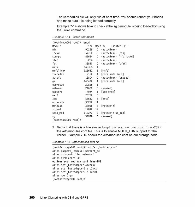
The rc.modules file will only run at boot-time. You should reboot your nodes and make sure it is being loaded correctly.
Example 7-14 shows how to check if the sg.o module is being loaded by using the lsmod command.
Example 7-14 lsmod command
[root@node001 root]# lsmodModule Size Used by Tainted: PFnfs 90268 0 (autoclean)lockd 57760 0 (autoclean) [nfs]sunrpc 81684 0 (autoclean) [nfs lockd]vfat 12284 2 (autoclean)fat 38840 0 (autoclean) [vfat]mmfs 642368 1mmfslinux 125632 1 [mmfs]tracedev 9152 1 [mmfs mmfslinux]autofs 12804 0 (autoclean) (unused)gm 446432 1 [mmfs mmfslinux]eepro100 20816 1usb-ohci 21600 0 (unused)usbcore 77024 1 [usb-ohci]ext3 70752 5jbd 53632 5 [ext3]mptscsih 36212 11mptbase 38016 3 [mptscsih]sd_mod 12896 12scsi_mod 112272 2 [mptscsih sd_mod]sg 34500 0 (unused)[root@node001 root]#
2. Verify that there is a line similar to options scsi_mod max_scsi_luns=255 in the /etc/modules.conf file. This is to enable MULTI_LUN support for the kernel. Example 7-15 shows the /etc/modules.conf on our storage node.
Example 7-15 /etc/modules.conf file
[root@storage001 root]# cat /etc/modules.confalias parport_lowlevel parport_pcalias usb-controller usb-ohcialias eth0 eepro100options scsi_mod max_scsi_luns=255alias scsi_hostadapter aic7xxxalias scsi_hostadapter1 aic7xxxalias scsi_hostadapter2 qla2200alias myri0 gm[root@storage001 root]#
200 Linux Clustering with CSM and GPFS

Once the above two steps are complete, you can start configuring your external Fibre Channel connected storage.
IBM Cluster 1350 comes with an optional IBM TotalStorage FAStT200HA Storage Server or IBM TotalStorage FAStT700 Storage Server and EXP700 storage enclosure.
Before starting to use your external storage, you have to configure the array and logical drive using IBM FAStT Storage Manager. Refer to the official product documentation on how to perform this configuration. For IBM TotalStorage FAStT200HA, refer to the following site:
http://www.pc.ibm.com/qtechinfo/MIGR-43824.html
For IBM TotalStorage FAStT700, refer to the following site:
http://www.pc.ibm.com/qtechinfo/MIGR-40358.html
Figure 7-1 shows a sample configuration using an IBM Total Storage FAStT200 Storage Server and QLogic QLA2200 host bus adapter.
Figure 7-1 FAStT logical disk configuration
Because GPFS will distribute workloads across the disks, it is suggested that you assign the same size and the same RAID level for each logical drive.
Chapter 7. GPFS installation and configuration 201

Red Hat Linux 7.3 has QLogic driver build in it, so it will recognize the host bus adapter and external storage directly, but you might want to check the http://www.pc.ibm.com/support site for the latest firmware and driver.
To see whether your host bus adapter and FAStT Storage Server have been detected, you may browse through /var/log/messages and find messages similar to the ones highlighted in Example 7-16 or simply run the dmesg command and search the word QLogic. The dmesg command, which is used to print kernel messages, is very useful in determining if a piece of hardware has been found, and if so, what device name has been assigned.
Example 7-16 Detect the hardware
scsi2 : QLogic QLA2200 PCI to Fibre Channel Host Adapter: bus 2 device 4 irq 22 Firmware version: 2.01.35, Driver version 5.31.RH1 Vendor: IBM Model: 3542 Rev: 0401 Type: Direct-Access ANSI SCSI revision: 03 Vendor: IBM Model: 3542 Rev: 0401 Type: Direct-Access ANSI SCSI revision: 03 Vendor: IBM Model: 3542 Rev: 0401 Type: Direct-Access ANSI SCSI revision: 03scsi(2:0:0:0): Enabled tagged queuing, queue depth 16.scsi(2:0:0:1): Enabled tagged queuing, queue depth 16.scsi(2:0:0:2): Enabled tagged queuing, queue depth 16.Attached scsi disk sdd at scsi2, channel 0, id 0, lun 0Attached scsi disk sde at scsi2, channel 0, id 0, lun 1Attached scsi disk sdf at scsi2, channel 0, id 0, lun 2SCSI device sdd: 142028800 512-byte hdwr sectors (72719 MB) sdd: unknown partition tableSCSI device sde: 142028800 512-byte hdwr sectors (72719 MB) sde: unknown partition tableSCSI device sdf: 142028800 512-byte hdwr sectors (72719 MB) sdf: unknown partition table
The machine type of the IBM TotalStorage FAStT200 is Model 3542. Example 7-16 shows that the IBM TotalStorage FAStT200 in our ITSO lab, which is attached to the QLogic QLA2200 Fibre Channel Host Adapter, is detected as scsi2. In addition to that, the example shows that the three logical drivers created using the IBM FAStT Storage Manager are recognized as sdd, sde, and sdf, respectively. In addition to that, you should notice that there is a message unknown partition table beside each device. It is because we have not create a partition to the disk yet. You need to create partition for each disk before starting to use them as your GPFS storage.
202 Linux Clustering with CSM and GPFS

In order to create a partition on those devices, you may use the fdisk command to create, for example, partitions on the devices /dev/sdd, /dev/sde, and /dev/sdf respectively, as follows:
# fdisk /dev/sdd# fdisk /dev/sde# fdisk /dev/sdf
The fdisk command will prompt for the type of partition (type n for new partition then p for creating a primary partition), the partition number (ranging from 1 to 4 in our example), the value of the first cylinder, and the value for the last cylinder (in our example, we accepted the default values). It also prompts you to accept the changes (pressing w to apply the changes and q to quit). Consult the official Red Hat Linux product documentation manual for a detailed explanation on how to create a partition using the fdisk command.
You can also use the fdisk command to verify that the partitions were created and display their attributes. Example 7-17 shows the fdisk command output in our ITSO lab environment. The /dev/sdd device now holds a partition named sdd1, /dev/sde holds the partition /dev/sde1, and dev/sdf holds the partition /dev/sdf1. Note that we run the fdisk command on the storage node from the management node using the ssh command.
Example 7-17 fdisk -l command output
[root@masternode bin]# ssh -n storage001 fdisk -l
Disk /dev/sda: 255 heads, 63 sectors, 2212 cylindersUnits = cylinders of 16065 * 512 bytes
Device Boot Start End Blocks Id System/dev/sda1 * 1 6 48163+ 83 Linux/dev/sda2 7 267 2096482+ 83 Linux/dev/sda3 268 398 1052257+ 83 Linux/dev/sda4 399 2212 14570955 5 Extended/dev/sda5 399 529 1052226 82 Linux swap/dev/sda6 530 660 1052226 83 Linux/dev/sda7 661 725 522081 83 Linux
Disk /dev/sdb: 255 heads, 63 sectors, 2212 cylindersUnits = cylinders of 16065 * 512 bytes
Device Boot Start End Blocks Id System
Disk /dev/sdc: 255 heads, 63 sectors, 2212 cylindersUnits = cylinders of 16065 * 512 bytes
Device Boot Start End Blocks Id System
Chapter 7. GPFS installation and configuration 203

Disk /dev/sdd: 255 heads, 63 sectors, 8840 cylindersUnits = cylinders of 16065 * 512 bytes
Device Boot Start End Blocks Id System/dev/sdd1 1 8840 71007268+ 83 Linux
Disk /dev/sde: 255 heads, 63 sectors, 8840 cylindersUnits = cylinders of 16065 * 512 bytes
Device Boot Start End Blocks Id System/dev/sde1 1 8840 71007268+ 83 Linux
Disk /dev/sdf: 255 heads, 63 sectors, 8840 cylindersUnits = cylinders of 16065 * 512 bytes
Device Boot Start End Blocks Id System/dev/sdf1 1 8840 71007268+ 83 Linux[root@masternode bin]#
7.3.8 Setting PATH for the GPFS commandTo ease the GPFS installation, we suggest you add a path to the GPFS binary directory to your $PATH environment in all nodes. This is how we do it:
1. Create /cfmroot/etc/profile.d/mmfs.sh, which contains:
PATH=$PATH:/usr/lpp/mmfs/binMANPATH=$MANPATH:/usr/lpp/mmfs/man
2. Run # chmod 755 /cfmroot/etc/profile.d/mmfs.sh.
3. Run # cfmupdatenode -a.
This way, the cfmupdatenode command will distribute /etc/profile.d/mmfs.sh to all nodes, including its attributes.
7.4 GPFS installationUp to this point, we have prepare the environment and covered the basis to proceed with the GPFS installation. This section describes the steps to install the GPFS software using the rpm command. For detailed information, refer to the IBM General Parallel File System for Linux: Concepts, Planning, and Installation Guide, GA22-7844.
204 Linux Clustering with CSM and GPFS

The GPFS installation procedures are the following and will be described in the next sections:
1. Install all the source files.2. Build the GPFS portability layer.
7.4.1 Installing the source filesPrior to installing GPFS, the following packages for both the SRC and RSCT components need to be installed and up and running:
� src-*.i386.rpm� rsct.core.utils-*.i386.rpm� rsct.core-*.i386.rpm� rsct.basic-*.i386.rpm
However, if CSM has already been installed and configured on the nodes GPFS is about to be installed on, which would be our recommendation, most of the packages listed above have already been installed during the CSM installation. The only remaining package that needs to be installed on all nodes is rsct.basic-*.i386.rpm. If CSM has not been installed on the nodes, all SRC and RSCT packages must be included in the installation steps described below.
Keep in mind that GPFS and CSM should use the same level of SRC and RSCT code and CSM management server node should not be part of GPFS cluster nodes, because it adds other resource classes to SRC and RSCT subsystems. At the time of writing this book, the current levels of SRC and RSCT are SRC Version 1.2 and RSCT Version 2.3.
GPFS consists of four source files, which are:
� gpfs.base-*.i386.rpm � gpfs.msg.en_US-*.i386.rpm� gpfs.gpl-*.i386.rpm (only for the node that builds the GPFS portability layer)� gpfs.docs-*.i386.rpm (optional, but recommended)
Because all nodes in our cluster have CSM installed, there is no need to include all SRC and RSCT packages. The following are the four packages that need to be installed:
1. rsct.basic-*.i386.rpm2. gpfs.base-*.i386.rpm3. gpfs.msg.en_US-*.i386.rpm4. gpfs.docs-*.i386.rpm
Note that the gpfs.gpl-*.i386.rpm package will only be installed on the management node. After that, the GPFS portability layer will be built and distributed to all the other nodes.
Chapter 7. GPFS installation and configuration 205
The following are the installation steps:
1. Copy the rsct.basic-*.i386.rpm, gpfs.base-*.i386.rpm, gpfs.msg.en_US-*.i386.rpm, and gpfs.docs-*.i386.rpm files under the /csminstall/Linux/RedHat/7.3/i386/updates directory:
# cp rsct.basic-*.i386.rpm gpfs*.rpm \ /csminstall/Linux/RedHat/7.3/i386/updates
2. Move to the /csminstall/Linux/RedHat/7.3/i386/updates directory:
# cd /csminstall/Linux/RedHat/7.3/i386/updates
3. Run the smsupdatenode command to install the files to all nodes. For more information on smsupdatenode command, see Chapter 6, “Cluster management with CSM” on page 149:
# smsupdatenode -ai rsct*.rpm gpfs*.rpm
7.4.2 Building the GPFS open source portability layerYou have to build the GPFS open source portability layer manually in one node (in our case, the management node), then copy them through all nodes. Make sure that you have a prepared kernel source files. See 7.3.3, “Prepare kernel source file for GPFS and Myrinet adapter” on page 190 on how to prepare your kernel source.
Below are the steps to build GPFS open source portability layer. Also, check the /usr/lpp/mmfs/src/README file for more up to date information on building the GPFS Open Source portability layer:
1. Install gpfs.gpl-*.i386.rpm in the management node:
# rpm -ivh gpfs.gpl-1.3.0-0.noarch.rpm
2. Modify and export the SHARKCLONEROOT variable to the /usr/lpp/mmfs/src value:
# export SHARKCLONEROOT=/usr/lpp/mmfs/src
3. Move to the /usr/lpp/mmfs/src/config directory:
# cd /usr/lpp/mmfs/src/config
4. Make a copy of the site.mcr.proto file, renaming it to site.mcr:
# cp site.mcr.proto site.mcr
5. Edit the /usr/lpp/mmfs/src/config/site.mcr file. There are some sections that need to be checked, as shown in Example 7-18.
Example 7-18 Values changed in the /usr/lpp/mmfs/src/config/site.mcr file
[root@masternode config]# more site.mcr/* Copyright IBM 1995 */
206 Linux Clustering with CSM and GPFS

/* $Id: site.mcr.proto,v 1.371.4.3 2002/10/04 18:23:52 gjertsen Exp $ */......../* #define GPFS_ARCH_POWER */#define GPFS_ARCH_I386......../* Linux distribution (select/uncomment only one) */LINUX_DISTRIBUTION = REDHAT_LINUX......../* Linux kernel versions supported for each architecture */
#ifdef GPFS_ARCH_I386#define LINUX_KERNEL_VERSION 2041800........[root@masternode config]#
In addition, uncomment any desired Linux kernel patches listed under the LINUX_PATCH_DEFINES section. The kernel will also need to be rebuilt and installed with the appropriate patches, which can be obtained at the following site:
http://www.ibm.com/developerworks/oss/linux/patches/
For detailed information on each patch, check the GPFS Frequently Asked Questions at:
http://www.ibm.com/servers/eserver/clusters/software/gpfs.html
6. Create your customized portability layer under the /usr/lpp/mmfs/src directory:
# make World# make InstallImages
Make sure that you type World with a capitalized W instead of world.
After you have issued the make InstallImages command, the mmfslinux, lxtrace, tracedev, and dumpconv files will be installed in /usr/lpp/mmfs/bin.
7. Copy the above binaries to the /cfmroot/usr/lpp/mmfs/bin directory and distribute them to all nodes using the cfmupdatenode command:
# mkdir -p /cfmroot/usr/lpp/mmfs/bin# cd /usr/lpp/mmfs/bin# cp mmfslinux lxtrace tracedev dumpconv /cfmroot/usr/lpp/mmfs/bin
Note: If you are building a portability layer for the SuSe distribution of Linux, you must also copy the autoconf.h and version.h header files into the Linux source tree:
cp /boot/vmlinuz.autoconf.h \ /lib/modules/‘uname -r‘/build/include/linux/autoconf.hcp /boot/vmlinuz.version.h \
/lib/modules/‘uname -r‘/build/include/linux/version.h
Chapter 7. GPFS installation and configuration 207

# cfmupdatenode -a
7.5 Creating the GPFS clusterThe first thing you must do in the process of creating a GPFS cluster is to define the characteristics of the cluster through the mmcrcluster command. The following are a brief description of the mmcrcluster command line options:
-n A list of node descriptors. You must provide a descriptor for each node to be added to the GPFS cluster. Each descriptor must be specified in the form primaryNetworkNodeName::secondaryNetworkNodeName. Those descriptors should be defined in a text file one per line.
-t The type of the cluster to be defined. At the time of writing this book, the only valid value is lc.
-p This is the primary GPFS cluster data server node used to store the GPFS cluster data.
-s Specifies the secondary GPFS cluster data server node used to store the GPFS cluster data. It is suggested that you specify a secondary GPFS cluster data server to prevent the loss of configuration data in the event your primary GPFS cluster data server goes down.
-r Specify the remote shell to be used. The default value is rsh. As CSM has already been installed in our cluster and it uses ssh as the remote shell, we will need to specify /usr/bin/ssh in this option.
-R Specify the remote file copy command to be used. The default value is rcp. Similarly to the remote shell option, we will need to specify /usr/bin/scp in this option.
7.5.1 Creating the GPFS nodes descriptor fileWhen creating your GPFS cluster, you need to provide a file containing a list of node descriptors, one per line for each node to be included in the cluster, including the storage nodes. Each descriptor must be specified in the form:
primaryNetworkNodeName::secondaryNetworkNodeName
Where:
primaryNetworkNodeName The host name of the node on the primary network for GPFS daemon to daemon communication.
designation Currently unused and specified by the double colon ::.
208 Linux Clustering with CSM and GPFS

secondaryNetworkNodeName The host name of the node on the secondary network, if one exists.
You may configure a secondary network node name in order to prevent the node from appearing to have gone down when the network is merely saturated. During times of excessive network traffic, if a second network is not specified, there is the potential for the RSCT component to be unable to communicate with the node over the primary network. RSCT would perceive the node as having failed and inform GPFS to perform node recovery.
Example 7-19 shows the contents the GPFS descriptors file we have created using the primaryNetworkNodeName as the one defined in our Myrinet network and the secondaryNetworkNodeName as the one defined in our Cluster network.
Example 7-19 /tmp/gpfs.allnodes file
[root@storage001 root]# cat /tmp/gpfs.allnodesstorage001-myri0::storage001node001-myri0::node001node002-myri0::node002node003-myri0::node003node004-myri0::node004[root@storage001 root]#
7.5.2 Defining the GPFS clusterIt is time now to run the mmcrcluster command to define the GPFS cluster. In our lab environment, we defined storage001-myri0 as the primary network for GPFS communication, ssh as remote shell command, scp as remote file copy commands, and lc for the cluster type. Example 7-20 on page 209 shows the output of the mmcrcluster command.
Example 7-20 mmcrcluster command output
[root@storage001 root]# mmcrcluster -t lc -p storage001-myri0.cluster.com -n \ /tmp/gpfs.allnodes -r /usr/bin/ssh -R /usr/bin/scpWed Oct 23 15:19:33 CDT 2002: mmcrcluster: Processing node storage001-myri0.cluster.comWed Oct 23 15:19:35 CDT 2002: mmcrcluster: Processing node node001-myri0.cluster.comWed Oct 23 15:19:36 CDT 2002: mmcrcluster: Processing node node002-myri0.cluster.comWed Oct 23 15:19:38 CDT 2002: mmcrcluster: Processing node node003-myri0.cluster.comWed Oct 23 15:19:40 CDT 2002: mmcrcluster: Processing node node004-myri0.cluster.comWed Oct 23 15:19:43 CDT 2002: mmcrcluster: Initializing needed RSCT subsystems.
Chapter 7. GPFS installation and configuration 209

mmcrcluster: Command successfully completed[root@storage001 root]#
This command, as with almost all GPFS commands, may take some time to execute, because it executes many tasks in all the nodes. Wait until the command finishes its execution, with success or not. If you stop its execution, the cluster definitions may not be fully created.
If one or more nodes are unavailable during the cluster definition, the mmcrcluster command will issue warnings regarding the nodes and they must be included in the cluster later using the mmaddcluster command.
After creating the cluster definitions, you can see the definitions using the mmlscluster command, as in Example 7-21.
Example 7-21 mmlscluster command output
[root@storage001 root]# mmlscluster
GPFS cluster information======================== Cluster id: gpfs1034298448 Remote shell command: /usr/bin/ssh Remote file copy command: /usr/bin/scp Primary network: myrinet Secondary network: ether
GPFS cluster data repository servers:------------------------------------- Primary server: storage001-myri0.cluster.com Secondary server: (none)
Cluster nodes that are not assigned to a nodeset:------------------------------------------------- 1 storage001-myri0 10.2.1.141 storage001-myri0.cluster.com 10.0.3.141 2 node001-myri0 10.2.1.1 node001-myri0.cluster.com 10.0.3.1
3 node002-myri0 10.2.1.2 node002-myri0.cluster.com 10.0.3.24 node003-myri0 10.2.1.3 node003-myri0.cluster.com 10.0.3.35 node004-myri0 10.2.1.4 node004-myri0.cluster.com 10.0.3.4
[root@storage001 root]#
210 Linux Clustering with CSM and GPFS

7.6 Creating the GPFS nodesetYou may have different nodesets within the GPFS cluster. A nodeset is a group of some or all of the GPFS nodes in a cluster, but all GPFS nodes must be in the cluster definition, and a node must be in one nodeset only.
The mmconfig command is responsible for creating the nodeset. The file containing the nodes in this nodeset is defined with the -n <nodename> parameter or -a for all nodes.
The following optional parameters can be also used:
-C Defines the name of the nodeset. If not specified, GPFS assigns an integer as the nodeset name: 1, 2, 3, and so on.
-M Specifies the amount of files to be cached. The default value is 1000.
-p The size of the cache on each node. The pagepool default value is 20 MB.
-P The communication protocol to be used for inter-node communication. Valid values are TCP and LAPI. The default is TCP.
-A Sets the nodes to start the GPFS daemons at boot time.
-D GPFS can generate dumps in case of problems in the file systems in the nodeset. This option will define the location of those dump files. The default value is /tmp/mmfs.
When we defined the nodeset in our lab, we did not define any name for the nodeset and will take the default name GPFS would assign to the cluster, which is 1, and will take the rest of parameter as the default, as shown in Example 7-22 on page 211.
Example 7-22 mmconfig command
[root@storage001 root]# mmconfig -aAmmconfig: Command successfully completedmmconfig: Propagating the changes to all affected nodes.This is an asynchronous process.[root@storage001 root]#
After issuing the mmconfig command, you can verify the nodeset definitions using the mmlsconfig command with the unique -C defining the name of the nodeset; if no nodeset name is specified, or if you specify . (dot) as the name of the nodeset (-C . ), the mmlsconfig command will display the configuration for nodeset to which the node executing the command belongs (this is valid for all commands that have the -C parameter). The output of the mmlsconfig command can be seen in Example 7-23.
Chapter 7. GPFS installation and configuration 211

Example 7-23 mmlsconfig command
[root@storage001 root]# mmlsconfigConfiguration data for nodeset 1:---------------------------------clusterType lccomm_protocol TCPmultinode yesautoload yesuseSingleNodeQuorum nogroup Gpfs.1recgroup GpfsRec.1
File systems in nodeset 1:--------------------------(none)[root@storage001 root]#
7.7 Starting GPFSAfter creating the nodeset, you can start the GPFS services on every node in the nodeset by issuing the mmstartup command with the -a or -C parameter and nodeset name. The -a parameter will start GPFS on all nodes in the nodeset while -C parameter with nodeset name will start the GPFS on the specified nodeset. Example 7-24 on page 212 shows the output of mmstartup command.
Example 7-24 mmstartup command
[root@storage001 root]# mmstartup -aWed Oct 23 15:29:51 CDT 2002: mmstartup: Starting GPFS ...storage001-myri0.cluster.com: 0513-059 The cthats Subsystem has been started. Subsystem PID is 10008.storage001-myri0.cluster.com: 0513-059 The cthags Subsystem has been started. Subsystem PID is 10227.storage001-myri0.cluster.com: 0513-059 The mmfs Subsystem has been started. Subsystem PID is 10417.node001-myri0.cluster.com: 0513-059 The cthats Subsystem has been started. Subsystem PID is 15766.node001-myri0.cluster.com: 0513-059 The cthags Subsystem has been started. Subsystem PID is 15883.node001-myri0.cluster.com: 0513-059 The mmfs Subsystem has been started. Subsystem PID is 15971.node002-myri0.cluster.com: 0513-059 The cthats Subsystem has been started. Subsystem PID is 28224.node002-myri0.cluster.com: 0513-059 The cthags Subsystem has been started. Subsystem PID is 28341.
212 Linux Clustering with CSM and GPFS

node002-myri0.cluster.com: 0513-059 The mmfs Subsystem has been started. Subsystem PID is 28429.node003-myri0.cluster.com: 0513-059 The cthats Subsystem has been started. Subsystem PID is 14675.node003-myri0.cluster.com: 0513-059 The cthags Subsystem has been started. Subsystem PID is 14792.node003-myri0.cluster.com: 0513-059 The mmfs Subsystem has been started. Subsystem PID is 14880.node004-myri0.cluster.com: 0513-059 The cthats Subsystem has been started. Subsystem PID is 27977.node004-myri0.cluster.com: 0513-059 The cthags Subsystem has been started. Subsystem PID is 28094.node004-myri0.cluster.com: 0513-059 The mmfs Subsystem has been started. Subsystem PID is 28182.[root@storage001 root]#
7.8 Disk definitionsIn this section, we show you how to define disks with the NSD server (see 4.2.2, “GPFS Network Shared Disk considerations” on page 81 for information on disk access models on GPFS cluster).
7.8.1 GPFS nodeset with NSD network attached serversA nodeset with NSD network attached servers means that all access to the disks and replication will be through one or two storage attached servers (also known as storage node). If your cluster has an internal network segment, this segment will be used for this purpose.
As mentioned in 4.2.2, “GPFS Network Shared Disk considerations” on page 81, NSD network attached disks are connected to one or two storage attached servers only. If a disk is defined with one storage attached server only, and the server fails, the disks would become unavailable to GPFS. If the disk is defined with two NSD network attached servers, then GPFS automatically transfers the I/O requests to the backup server.
Note: GPFS does not support using different disk access models within the same nodeset.
Chapter 7. GPFS installation and configuration 213

Creating Network Shared Disks (NSDs)You will need to create a descriptor file before creating your NSDs. This file should contain information about each disk that will be a NSD, and should have the following syntax:
DeviceName:PrimaryNSDServer:SecondaryNSDServer:DiskUsage:FailureGroup
Where:
DeviceName The real device name of the external storage partition (such as /dev/sde1).
PrimaryServer The host name of the server that the disk is attached to; Remember you must always use the node names defined in the cluster definitions.
SecondaryServer The server where the secondary disk attachment is connected.
DiskUsage The kind of information should be stored in this disk. The valid values are data, metadata, and dataAndMetadata (default).
FailureGroup An integer value (0 to 4000) that identifies the failure group to which this disk belongs. All disks with a common point of failure must belong to the same failure group. The value -1 indicates that the disk has no common point of failure with any other disk in the file system. GPFS uses the failure group information to assure that no two replicas of data or metadata are placed in the same group and thereby become unavailable due to a single failure. When this field is not specified, GPFS assigns a failure group (higher than 4000) automatically to each disk.
Example 7-25 shows a descriptor file named /tmp/descfile, which contains NSD information defined in our cluster.
Example 7-25 /tmp/descfile file
[root@storage001 root]# cat /tmp/descfile/dev/sdd1:storage001-myri0.cluster.com::dataAndMetadata:1/dev/sde1:storage001-myri0.cluster.com::dataAndMetadata:1/dev/sdf1:storage001-myri0.cluster.com::dataAndMetadata:1[root@storage001 root]#
Now we can create the Network Shared Disks by using the mmcrnsd command, as shown in Example 7-26.
214 Linux Clustering with CSM and GPFS

Example 7-26 mmcrnsd command
[root@storage001 root]# mmcrnsd -F /tmp/descfile mmcrnsd: Propagating the changes to all affected nodes.This is an asynchronous process.[root@storage001 root]#
After successfully creating the NSD for GPFS cluster, mmcrnsd will comment the original disk device and put the GPFS assigned global name for that disk device at the following line. Example 7-27 shows the modification that was made by the mmcrnsd command.
Example 7-27 /tmp/descfile (modified)
[root@storage001 root]# cat /tmp/descfile# /dev/sdd1:storage001-myri0.cluster.com::dataAndMetadata:1gpfs1nsd:::dataAndMetadata:1# /dev/sde1:storage001-myri0.cluster.com::dataAndMetadata:1gpfs2nsd:::dataAndMetadata:1# /dev/sdf1:storage001-myri0.cluster.com::dataAndMetadata:1gpfs3nsd:::dataAndMetadata:1[root@storage001 root]#
Sometimes you are using a disk to create a new NSD that already contained an NSD that has been terminated. In this situation, mmcrnsd may complain that the disk is already an NSD. Example 7-28 shows an example of the error message.
Example 7-28 Error message in mmcrnsd output
[root@node001 root ] # mmcrnsd -F /tmp/descfilemmcrnsd:Disk descriptor /dev/sde1:node001::dataAndMetadata:1 refers to anexisting NSD[root@storage001 root]#
In this case, if you are sure that the disk is not an in-use NSD, you can override the checking by using the -v no option. For example, the default value is -v yes to verify all devices. See Example 7-29 for details.
Example 7-29 -v no option
[root@node001 root]# mmcrnsd -F /tmp/descfile -v nommcrnsd: Propagating the changes to all affected nodes.This is an asynchronous process.[root@storage001 root]#
You can see the new device names by using the mmlsnsd command. Example 7-30 shows the output of the mmlsnsd command.
Chapter 7. GPFS installation and configuration 215

Example 7-30 mmlsnsd command
[root@storage001 root]# mmlsnsd
File system NSD name Primary node Backup node--------------------------------------------------------------------------- (free disk) gpfs1nsd storage001-myri0.cluster.com (free disk) gpfs2nsd storage001-myri0.cluster.com (free disk) gpfs3nsd storage001-myri0.cluster.com[root@storage001 root]#
You can also use the -m or -M parameter in the mmlsnsd command to see the mapping between the specified global NSD disk names and their local device names. Example 7-31 shows the output of the mmlsnsd -m command.
Example 7-31 mmlsnsd -m output
[root@storage001 root]# mmlsnsd -m
NSD name PVID Device Node name Remarks------------------------------------------------------------------------------------- gpfs1nsd 0A00038D3DB70FE0 /dev/sdd1 storage001-myri0.cluster.com primary node gpfs2nsd 0A00038D3DB70FE1 /dev/sde1 storage001-myri0.cluster.com primary node gpfs3nsd 0A00038D3DB70FE2 /dev/sdf1 storage001-myri0.cluster.com primary node[root@storage001 root]#
Creating the GPFS file systemOnce you have your NSDs ready, you can create the GPFS file system. In order to create the file system, you will use the mmcrfs command, where you must define the following attributes in this order:
1. The mount point.
2. The name of the device for the file system.
3. The descriptor file (-F).
4. The name of the nodeset the file system will reside on (-C) if you defined a nodeset name when creating the cluster.
The mmcrfs command will format the NSDs and get them ready to mount the file system, as well as adding an entry in the /etc/fstab file for the new file system and its mounting point.
Some of the optional parameters are:
-A [yes|no] Auto-mount the file system. The default value is yes.
216 Linux Clustering with CSM and GPFS

-B Block size for the file system. Default value is 256 KB, and can be changed to 16 KB, 64 KB, 512 KB, or 1024 KB. If you plan to have a file system with block size of 512 KB or 1024 KB, you must also set the value of the maxblocksize nodeset parameter using the mmchconfig command.
-M Maximum metadata replicas (maxDataReplicas). The default value is 1 and might be changed to 2.
-r Default data replicas. The default value is 1 and valid values are 1 and 2; This factor cannot be larger than maxDataReplicas.
-R Maximum data replicas. The default value is 1 and another valid value is 2.
-m Default metadata replicas. The default value is 1 and another valid value is 2. This factor cannot be larger than maxMetadataReplicas.
-n Estimated number of nodes to mount the file system. The default value is 32 and it is used to estimate the size of the data structure for the file system.
Some of the information above must be defined during the creation of the file system and cannot not be changed later. These parameters are:
� Block size� maxDataReplicas� maxMetadataReplicas� NumNodes
The rest of the file system parameters can be changed with the mmchfs command.
When creating our GPFS file systems in our lab environment, we used the default settings of block size value, number of nodes to mount the file system on, maxDataReplicas, and maxMetadataReplicas, which is 1, as shown in Example 7-32.
Example 7-32 Create NSD file system
[root@storage001 root]# mmcrfs /gpfs gpfs0 -F /tmp/descfile -A yes
The following disks of gpfs0 will be formatted on node storage001.cluster.com: gpfs1nsd: size 71007268 KB gpfs2nsd: size 71007268 KB gpfs3nsd: size 71007268 KBFormatting file system ...Creating Inode File 19 % complete on Wed Oct 23 16:24:14 2002 39 % complete on Wed Oct 23 16:24:19 2002
Chapter 7. GPFS installation and configuration 217

59 % complete on Wed Oct 23 16:24:24 2002 78 % complete on Wed Oct 23 16:24:29 2002 98 % complete on Wed Oct 23 16:24:34 2002 100 % complete on Wed Oct 23 16:24:35 2002Creating Allocation MapsClearing Inode Allocation MapClearing Block Allocation MapFlushing Allocation MapsCompleted creation of file system /dev/gpfs0.mmcrfs: Propagating the changes to all affected nodes.This is an asynchronous process.
[root@storage001 root]#
Sometimes you may receive an error message when creating a file system using NSDs that were in use for other file systems, as shown in Example 7-33. If you are sure that the disks are not in use anymore, you can override the verification by issuing the mmcrfs command with the -v no option. The output would be the same as the previous example.
Example 7-33 Error message with mmcrfs command
[root@storage001 root]# mmcrfs /gpfs gpfs0 -F /tmp/descfile -A yesmmcrfs: There is already an existing file system using gpfs0[root@storage001 root]#
After creating the file system, you can run mmlsfs command to display your file system attributes. Example 7-34 on page 218 shows the output of the mmlsfs command.
Example 7-34 mmlsfs command output
[root@storage001 root]# mmlsfs gpfs0flag value description---- -------------- ----------------------------------------------------- -s roundRobin Stripe method -f 8192 Minimum fragment size in bytes -i 512 Inode size in bytes -I 16384 Indirect block size in bytes -m 1 Default number of metadata replicas -M 1 Maximum number of metadata replicas -r 1 Default number of data replicas -R 1 Maximum number of data replicas -D posix Do DENY WRITE/ALL locks block NFS writes(cifs) or not(posix)? -a 1048576 Estimated average file size -n 32 Estimated number of nodes that will mount file system -B 262144 Block size
218 Linux Clustering with CSM and GPFS

-Q none Quotas enforced none Default quotas enabled -F 104448 Maximum number of inodes -V 6.00 File system version. Highest supported version: 6.00 -d gpfs1nsd Disks in file system -A yes Automatic mount option -C 1 GPFS nodeset identifier -E no Exact mtime default mount option -S no Suppress atime default mount option -o none Additional mount options[root@storage001 root]#
You may also run mmlsdisk to display the current configuration and state of the disks in a file system. Example 7-35 shows the output of the mmlsdisk command
Example 7-35 mmlsdisk command
[root@storage001 root]# mmlsdisk gpfs0disk driver sector failure holds holdsname type size group metadata data status availability------------ -------- ------ ------- -------- ----- ------------- ------------gpfs1nsd nsd 512 1 yes yes ready upgpfs2nsd nsd 512 1 yes yes ready upgpfs3nsd nsd 512 1 yes yes ready up[root@storage001 root]#
After creating the file system, GPFS will add a new file system in /etc/fstab, as show in Example 7-36 on page 219.
Example 7-36 /etc/fstab file
[root@storage001 root]# less /etc/fstab.../dev/gpfs0 /gpfs gpfs dev=/dev/gpfs0,autostart 0 0...[root@storage001 root]#
Mount GPFS file systemThe newly created GPFS file system will not automatically be mounted when you just installed GPFS cluster. To mount GPFS file system in all nodes after creating GPFS cluster, go to the management node and run:
# dsh -av mount /gpfs
Unless you use the -A no parameter with the mmcrfs command, your GPFS file system will be mounted automatically every time you start GPFS.
Chapter 7. GPFS installation and configuration 219

7.8.2 GPFS nodeset with direct attached disksThe creation of the disks in an environment with direct attached disks is quite similar to the steps described for the environment with NSD servers in 7.8.1, “GPFS nodeset with NSD network attached servers” on page 213. The differences relate to how the disks will be accessed.
Defining disksIn this case, the disks will not be attached to one server only, but all disks will have a direct connection to all of the nodes through the Fibre Channel switch. Therefore, there will be no need to specify primary or secondary servers for any of the disks, and the disk description file will have the second, third, and fifth fields specified in a different way.
The primary and secondary servers fields must be left null, and the last field must indicate that there is no common point of failure with any other disk in the nodeset. This can be done by specifying a failure group of -1, as in Example 7-37 on page 220.
Example 7-37 Failure group of -1
[root@storage /tmp]# cat disk_def/dev/sda:::dataAndMetadata:-1/dev/sdb:::dataAndMetadata:-1/dev/sdc:::dataAndMetadata:-1/dev/sdd:::dataAndMetadata:-1/dev/sde:::dataAndMetadata:-1[root@storage /tmp]#
After defining the disks you can verify them using the mmlsnsd command. This option shows all the disks for all the nodes, as in Example 7-38.
It is very important to note that it is not mandatory for the servers to have the same disk structure or amount of internal disks. The names of the disks can be different for each server. For example, in Example 7-38, you can verify that the first disk, with disk ID C0A800E93BE1DAF6, is named /dev/sda for node1, while in node2 its name is /dev/sdb.
Note: When trying to mount the GPFS file system in our ITSO lab environment using the mount /dev/gpfs / gpfs command, we received several kernel error messages. It may have been caused by the fact that the system does not know the file system type GPFS uses (GPFS file system).
220 Linux Clustering with CSM and GPFS

GPFS refers to the disks using the disk ID, so you do not have to worry about the /dev/ names for the disks being different among the GPFS nodes.
Example 7-38 mmlsnsd command
[root@node1 /root]# mmlsnsd -M
NSD name PVID Device Node name Remarks--------------------------------------------------------------------------------------- gpfs1nsd C0A800E93BE1DAF6 /dev/sda node1 directly attached gpfs1nsd C0A800E93BE1DAF6 /dev/sdb node2 directly attached gpfs1nsd C0A800E93BE1DAF6 /dev/sdb node3 directly attached gpfs2nsd C0A800E93BE1DAF7 /dev/sdb node1 directly attached gpfs2nsd C0A800E93BE1DAF7 /dev/sdc node2 directly attached gpfs2nsd C0A800E93BE1DAF7 /dev/sdc node3 directly attached gpfs3nsd C0A800E93BE1DAF8 /dev/sdc node1 directly attached gpfs3nsd C0A800E93BE1DAF8 /dev/sdd node2 directly attached gpfs3nsd C0A800E93BE1DAF8 /dev/sdd node3 directly attached gpfs4nsd C0A800E93BFA7D86 /dev/sdd node1 directly attached gpfs4nsd C0A800E93BFA7D86 /dev/sde node2 directly attached gpfs4nsd C0A800E93BFA7D86 /dev/sde node3 directly attached gpfs5nsd C0A800E93BFA7D87 /dev/sde node1 directly attached gpfs5nsd C0A800E93BFA7D87 /dev/sdf node2 directly attached gpfs5nsd C0A800E93BFA7D87 /dev/sdf node3 directly attached[root@node1 /root]#
7.9 Exporting a GPFS file system using NFSA GPFS file system can be exported to other hosts that are not part of the GPFS cluster. The process of exporting a GPFS file system to other servers is exactly the same as any ordinary file system through NFS.
7.10 GPFS shutdownYou can shut down all GPFS file systems and daemons using the mmshutdown command. This command umounts all GPFS file systems mounted on the localhost and shuts down all GPFS-related daemons.
If you want to shut down GPFS on a local node only, issue the mmshutdown command without any parameters, as shown in Example 7-39.
Example 7-39 Shut down a local node
[root@storage001 bin]# mmshutdown
Chapter 7. GPFS installation and configuration 221

Thu Nov 23 23:08:16 CDT 2002: mmshutdown: Starting force unmount of GPFS file systemsThu Nov 23 23:08:21 CDT 2002: mmshutdown: Shutting down GPFS daemons0513-044 The mmfs Subsystem was requested to stop.Shutting down!'shutdown' command about to kill process 30872Thu Nov 23 23:08:23 CDT 2002: mmshutdown: Finished[root@storage001 bin]#
If you want to shut down all GPFS nodes in the nodeset, issue the mmshutdown command with the -a parameter. Because you can run GPFS administrative commands from any node that belongs to the GPFS cluster, Example 7-40 shows the mmshutdown -a being executed in node001.
Example 7-40 Shut down all nodes in the nodeset
[root@node001 root]# mmshutdown -aTue Nov 23 23:20:42 CDT 2002: mmshutdown: Starting force unmount of GPFS file systemsTue Nov 23 23:20:47 CDT 2002: mmshutdown: Shutting down GPFS daemonsstorage001-myri0.cluster.com: 0513-044 The mmfs Subsystem was requested to stop.node001-myri0.cluster.com: 0513-044 The mmfs Subsystem was requested to stop.node002-myri0.cluster.com: 0513-044 The mmfs Subsystem was requested to stop.node003-myri0.cluster.com: 0513-044 The mmfs Subsystem was requested to stop.node004-myri0.cluster.com: 0513-044 The mmfs Subsystem was requested to stop.storage001-myri0.cluster.com: Shutting down!storage001-myri0.cluster.com: 'shutdown' command about to kill process 1428node001-myri0.cluster.com: Shutting down!node001-myri0.cluster.com: 'shutdown' command about to kill process 1646node002-myri0.cluster.com: Shutting down!node002-myri0.cluster.com: 'shutdown' command about to kill process 1730node003-myri0.cluster.com: Shutting down!node003-myri0.cluster.com: 'shutdown' command about to kill process 1727node004-myri0.cluster.com: Shutting down!node004-myri0.cluster.com: 'shutdown' command about to kill process 1732Tue Nov 23 23:20:49 CDT 2002: mmshutdown: Finished[root@node001 root]#
7.11 SummaryIn this chapter, we have provided information on how to install the GPFS software, how to create the GPFS cluster, and define the nodeset disks and file systems. This is the necessary information to make GPFS run.
222 Linux Clustering with CSM and GPFS

See Chapter 8, “Managing the GPFS cluster” on page 225 on how to manage the cluster by adding a new disk to an existing file system, delete a disk on an in-use file system, and some information on trouble-shooting, among other topics.
Chapter 7. GPFS installation and configuration 223

224 Linux Clustering with CSM and GPFS

Chapter 8. Managing the GPFS cluster
Managing a GPFS cluster implies managing the nodes in the nodeset, disks, and file systems. In this chapter, we cover some of the common tasks encountered when working with GPFS, including;
� Adding, removing, and replacing disks
� GPFS ACLs
� GPFS log and trace files and troubleshooting
8
© Copyright IBM Corp. 2002, 2004. All rights reserved. 225

8.1 Adding and removing disks from GPFSUnlike many traditional file systems, GPFS allows disks to be added and removed from the file system, even when it is mounted. In this section, we outline the procedures for working with disks.
8.1.1 Adding a new disk to an existing GPFS file systemFor this task, we will use a command that has not been discussed in this redbook before: mmadddisk. This command adds a new disk to a file system and optionally re-balances data onto the new disk.
Before adding the physical disk to the file system it must first be defined as an NSD. We will use mmcrnsd for this, as in 7.8.1, “GPFS nodeset with NSD network attached servers” on page 213.
In Example 8-1, we create an NSD using the second disk from node001.
Example 8-1 Creating an additional NSD with mmcrnsd
[root@storage001 root]# cat > newdisk.dsc/dev/sdb1:node001-myri0.cluster.com::dataAndMetadata:-1^D[root@storage001 root]# mmcrnsd -F newdisk.dscmmcrnsd: Propagating the changes to all affected nodes.This is an asynchronous process.[root@storage001 root]#
If the disk (/dev/sdb1 in this case) contains an NSD descriptor, the mmcrnsd command will fail. You can verify that the disk is not currently being used as an NSD by issuing the mmlsnsd -m command. After that, you can define the new disk by adding the -v no option to the mmcrnsd command line to disable disk verification.
Example 8-2 shows the use of the mmlsnsd command to verify that the NSD was created correctly. The newly created NSD should show up as (free disk), since it has not yet been assigned to a file system.
Example 8-2 Verifying correct NSD creation with mmlsnsd
[root@storage001 root]# mmlsnsdFile system NSD name Primary node Backup node--------------------------------------------------------------------------- gpfs0 gpfs2nsd storage001-myri0.cluster.com (free disk) gpfs3nsd node001-myri0.cluster.com[root@storage001 root]#
226 Linux Clustering with CSM and GPFS

Once the NSD has been successfully defined, we can use it to enlarge our GPFS file system with mmaddisk. Because GPFS paralyzes read and write operations, simply appending the disk to the file system is inefficient. Data will not be balanced across all the disks, so GPFS will be unable to make optimal use of the new disk. The mmadddisk command can automatically re-balance the data across all the disks through the use of the -r switch. In large file systems, the re-balance can take a long time, so we also supply the asynchronous switch (-a). This will cause the mmadddisk command to return while the re-balance continues in the background.
Example 8-3 shows the output of the mmadddisk command.
Example 8-3 Adding a disk to a GPFS file system with mmadddisk
[root@storage001 root]# mmadddisk gpfs0 -F newdisk.dsc -r -a
GPFS: 6027-531 The following disks of gpfs0 will be formatted on node storage001.cluster.com: gpfs3nsd: size 17767858 KBExtending Allocation MapGPFS: 6027-1503 Completed adding disks to file system gpfs0.mmadddisk: Propagating the changes to all affected nodes.This is an asynchronous process.[root@storage001 root]#
Using the mmlsdisk and mmlsnsd command, you can verify that the NSD is now a member of our GPFS file system, as in Example 8-4.
Example 8-4 Verifying the new NSD was added with mmlsdisk and mmlsnsd
[root@storage001 root]# mmlsdisk gpfs0disk driver sector failure holds holdsname type size group metadata data status availability------------ -------- ------ ------- -------- ----- ------------- ------------gpfs2nsd nsd 512 -1 yes yes ready upgpfs3nsd nsd 512 -1 yes yes ready up
Note: Although you can still access the file system while it is being re-balanced, certain GPFS metadata commands, including mmdf, cannot be run until the re-balance has completed.
Tip: Although disks can be re-balanced while the file system is running, it will affect the performance. You might want to think about adding the new disk(s) during a period of low activity, or re-balancing the disks at a later time with the mmrestripefs -b command.
Chapter 8. Managing the GPFS cluster 227
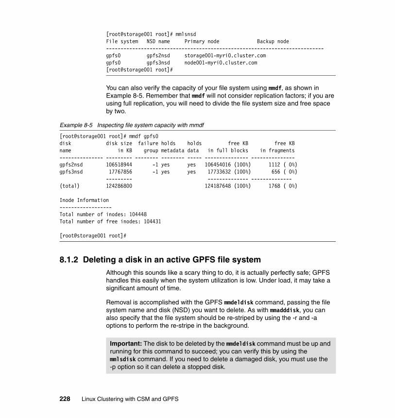
[root@storage001 root]# mmlsnsdFile system NSD name Primary node Backup node---------------------------------------------------------------------------gpfs0 gpfs2nsd storage001-myri0.cluster.comgpfs0 gpfs3nsd node001-myri0.cluster.com[root@storage001 root]#
You can also verify the capacity of your file system using mmdf, as shown in Example 8-5. Remember that mmdf will not consider replication factors; if you are using full replication, you will need to divide the file system size and free space by two.
Example 8-5 Inspecting file system capacity with mmdf
[root@storage001 root]# mmdf gpfs0disk disk size failure holds holds free KB free KBname in KB group metadata data in full blocks in fragments--------------- --------- -------- -------- ----- --------------- ---------------gpfs2nsd 106518944 -1 yes yes 106454016 (100%) 1112 ( 0%)gpfs3nsd 17767856 -1 yes yes 17733632 (100%) 656 ( 0%) --------- -------------- --------------(total) 124286800 124187648 (100%) 1768 ( 0%)
Inode Information------------------Total number of inodes: 104448Total number of free inodes: 104431
[root@storage001 root]#
8.1.2 Deleting a disk in an active GPFS file systemAlthough this sounds like a scary thing to do, it is actually perfectly safe; GPFS handles this easily when the system utilization is low. Under load, it may take a significant amount of time.
Removal is accomplished with the GPFS mmdeldisk command, passing the file system name and disk (NSD) you want to delete. As with mmadddisk, you can also specify that the file system should be re-striped by using the -r and -a options to perform the re-stripe in the background.
Important: The disk to be deleted by the mmdeldisk command must be up and running for this command to succeed; you can verify this by using the mmlsdisk command. If you need to delete a damaged disk, you must use the -p option so it can delete a stopped disk.
228 Linux Clustering with CSM and GPFS

Example 8-6 shows the removal of gpfs3nsd that we just added to our file system.
Example 8-6 Removing a disk from GPFS with mmdeldisk
[root@storage001 root]# mmdeldisk gpfs0 gpfs3nsd -r -aDeleting disks ...GPFS: 6027-589 Scanning file system metadata, phase 1 ... 31 % complete on Thu Nov 24 17:12:55 2002 62 % complete on Thu Nov 24 17:12:58 2002 93 % complete on Thu Nov 24 17:13:01 2002 100 % complete on Thu Nov 24 17:13:02 2002GPFS: 6027-552 Scan completed successfully.GPFS: 6027-589 Scanning file system metadata, phase 2 ...GPFS: 6027-552 Scan completed successfully.GPFS: 6027-589 Scanning file system metadata, phase 3 ...GPFS: 6027-552 Scan completed successfully.GPFS: 6027-565 Scanning user file metadata ... 84 % complete on Thu Nov 24 17:13:08 2002 100 % complete on Thu Nov 24 17:13:08 2002GPFS: 6027-552 Scan completed successfully.GPFS: 6027-370 tsdeldisk completed.mmdeldisk: Propagating the changes to all affected nodes.This is an asynchronous process.[root@storage001 root]#
Again, we can use the mmlsdisk and mmlsnsd commands to verify the successful removal of the disks, as in Example 8-7.
Example 8-7 Verifying successful disk removal with mmlsdisk and mmlsnsd
[root@storage001 root]# mmlsdisk gpfs0disk driver sector failure holds holdsname type size group metadata data status availability------------ -------- ------ ------- -------- ----- ------------- ------------gpfs2nsd nsd 512 -1 yes yes ready up# mmlsnsd
File system NSD name Primary node Backup node--------------------------------------------------------------------------- gpfs0 gpfs2nsd storage001-myri0.cluster.com (free disk) gpfs3nsd node001-myri0.cluster.com[root@storage001 root]#
Example 8-8 on page 230 shows how we could also have used mmlsnsd -F to show only free NSDs in our nodeset.
Chapter 8. Managing the GPFS cluster 229

Example 8-8 Listing free NSDs with mmlsnsd -F
[root@storage001 root]# mmlsnsd -F
File system NSD name Primary node Backup node--------------------------------------------------------------------------- (free disk) gpfs3nsd node001-myri0.cluster.com[root@storage001 root]#
8.1.3 Replacing a failing disk in an existing GPFS file systemGPFS allows for a failing disk to be replaced while the file system is up and running by using the mmrpldisk command. Although replacing with different size disks is supported, complications can arise and it should be avoided whenever possible. It is further recommended that you do not change the disk usage (data/metadata) or failure group if possible.
As when adding a new disk, the replacement disk must first be defined as an NSD. Example 8-9 shows the definition of the disk with the mmcrnsd command.
Example 8-9 Defining a replacement disk with mmcrnsd
[root@storage001 tmp]# cat > rpldisk.dsc/dev/sdb1:node002-myri0.cluster.com::dataAndMetadata:-1^D[root@storage001 tmp]# mmcrnsd -F rpldisk.dsc -v nommcrnsd: Propagating the changes to all affected nodes.This is an asynchronous process.[root@storage001 tmp]#
Now we can run, as shown in Example 8-10, the mmrpldisk command to actually perform the replacement. We replace failing disk gpfs3nsd with the newly created NSD.
Example 8-10 Replacing a disk with mmrpldisk
[root@storage001 tmp]# mmrpldisk gpfs0 gpfs3nsd -F rpldisk.dscReplacing gpfs3nsd ...
GPFS: 6027-531 The following disks of gpfs0 will be formatted on node storage001.cluster.com:
Important: You cannot use the mmrpldisk command to replace disks that have actually failed; they should be removed with the mmdeldisk -p command. Verify disks are available and up with the mmlsdisk command before attempting this procedure.
230 Linux Clustering with CSM and GPFS

gpfs5nsd: size 17767858 KBExtending Allocation MapGPFS: 6027-1503 Completed adding disks to file system gpfs0.GPFS: 6027-589 Scanning file system metadata, phase 1 ... 66 % complete on Thu Nov 24 17:42:44 2002 100 % complete on Thu Nov 24 17:42:45 2002GPFS: 6027-552 Scan completed successfully.GPFS: 6027-589 Scanning file system metadata, phase 2 ...GPFS: 6027-552 Scan completed successfully.GPFS: 6027-589 Scanning file system metadata, phase 3 ...GPFS: 6027-552 Scan completed successfully.GPFS: 6027-565 Scanning user file metadata ...GPFS: 6027-552 Scan completed successfully.Donemmrpldisk: Propagating the changes to all affected nodes.This is an asynchronous process.[root@storage001 tmp]#
We can now verify that the failing disk has been removed from the file system, as shown in Example 8-11.
Example 8-11 Using mmlsdisk and mmlsnsd to ensure a disk has been replaced
[root@storage001 tmp]# mmlsdisk gpfs0disk driver sector failure holds holdsname type size group metadata data status availability------------ -------- ------ ------- -------- ----- ------------- ------------gpfs2nsd nsd 512 -1 yes yes ready upgpfs4nsd nsd 512 -1 yes yes ready up# mmlsnsd -F
File system NSD name Primary node Backup node--------------------------------------------------------------------------- (free disk) gpfs3nsd node001-myri0.cluster.com[root@storage001 tmp]#
8.2 Removing all GPFS file systems and configurationIn a test environment, it is often useful to remove all GPFS configuration to the point where it is identical to a fresh install. This is also required if you want to uninstall GFFS.
Note: If you are replacing the failed disk with an identical disk (size, usage, and failure group), no re-balance is required. Otherwise, you may want to run use the mmrestripefs -b command sometime when system is not overloaded.
Chapter 8. Managing the GPFS cluster 231

The broad procedure is as follows:
1. Unmount all the file systems with umount.
It is easiest to do this using the dsh command. If you have multiple file systems, you must umount all of them.
2. Delete all file systems with mmdelfs.
Again, you must run the mmdelfs command once for each file system but it, like all the remaining commands in this process, need only be run on the GPFS primary node.
3. Delete all NSDs with mmdelnsd.
You will most certainly have multiple NSDs. Each one must be deleted using the mmdelnsd command.
4. Shutdown GPFS on all nodes with mmshutdown -a.
If you have multiple nodesets, you must run the mmshutdown -a command for each nodeset as follows:
# mmshutdown -C <nodeset> -a
5. Remove all nodes from nodeset with mmdelnode -a.
The removal should be done for each nodeset in the GPFS cluster using the mmdelnode command as follows:
# mmdelnode -C <nodeset> -a
6. And finally, remove the GPFS cluster definition with mmdelcluster -a.
Example 8-12 shows the commands we used to delete our small GPFS configuration. The commands were run exclusively on the GPFS primary node. All file systems were unmounted before we started.
Example 8-12 Removing all GPFS configuration from the primary node
[root@storage001 root]# mmdelfs /dev/gpfs0mmdelfs: Marking the disks as availableAll data on following disks of gpfs0 will be destroyed: gpfs1nsd gpfs2nsd gpfs3nsdCompleted deletion of file system /dev/gpfs0.mmdelfs: Propagating the changes to all affected nodes.This is an asynchronous process.
[root@storage001 root]# mmdelnsd 'gpfs1nsd;gpfs2nsd;gpfs3nsd'mmdelnsd: Propagating the changes to all affected nodes.
[root@storage001 root]# mmshutdown -a
232 Linux Clustering with CSM and GPFS
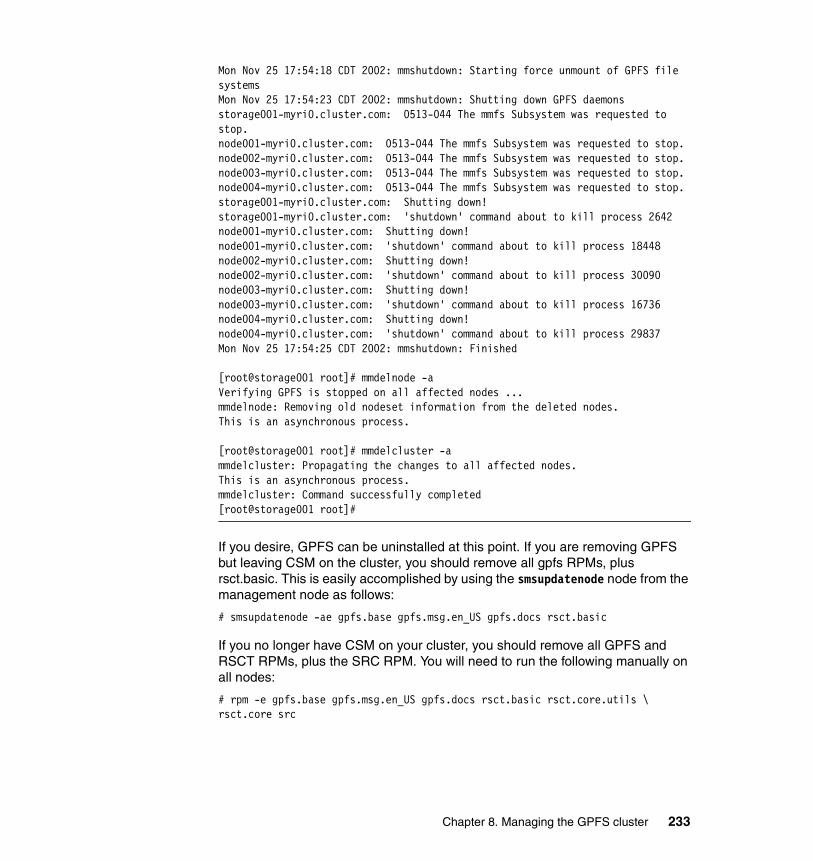
Mon Nov 25 17:54:18 CDT 2002: mmshutdown: Starting force unmount of GPFS file systemsMon Nov 25 17:54:23 CDT 2002: mmshutdown: Shutting down GPFS daemonsstorage001-myri0.cluster.com: 0513-044 The mmfs Subsystem was requested to stop.node001-myri0.cluster.com: 0513-044 The mmfs Subsystem was requested to stop.node002-myri0.cluster.com: 0513-044 The mmfs Subsystem was requested to stop.node003-myri0.cluster.com: 0513-044 The mmfs Subsystem was requested to stop.node004-myri0.cluster.com: 0513-044 The mmfs Subsystem was requested to stop.storage001-myri0.cluster.com: Shutting down!storage001-myri0.cluster.com: 'shutdown' command about to kill process 2642node001-myri0.cluster.com: Shutting down!node001-myri0.cluster.com: 'shutdown' command about to kill process 18448node002-myri0.cluster.com: Shutting down!node002-myri0.cluster.com: 'shutdown' command about to kill process 30090node003-myri0.cluster.com: Shutting down!node003-myri0.cluster.com: 'shutdown' command about to kill process 16736node004-myri0.cluster.com: Shutting down!node004-myri0.cluster.com: 'shutdown' command about to kill process 29837Mon Nov 25 17:54:25 CDT 2002: mmshutdown: Finished
[root@storage001 root]# mmdelnode -aVerifying GPFS is stopped on all affected nodes ...mmdelnode: Removing old nodeset information from the deleted nodes.This is an asynchronous process.
[root@storage001 root]# mmdelcluster -ammdelcluster: Propagating the changes to all affected nodes.This is an asynchronous process.mmdelcluster: Command successfully completed[root@storage001 root]#
If you desire, GPFS can be uninstalled at this point. If you are removing GPFS but leaving CSM on the cluster, you should remove all gpfs RPMs, plus rsct.basic. This is easily accomplished by using the smsupdatenode node from the management node as follows:
# smsupdatenode -ae gpfs.base gpfs.msg.en_US gpfs.docs rsct.basic
If you no longer have CSM on your cluster, you should remove all GPFS and RSCT RPMs, plus the SRC RPM. You will need to run the following manually on all nodes:
# rpm -e gpfs.base gpfs.msg.en_US gpfs.docs rsct.basic rsct.core.utils \ rsct.core src
Chapter 8. Managing the GPFS cluster 233

8.3 Access Control Lists (ACLs)The Access Control Lists for GPFS is a mechanism to restrict access to files in a GPFS file system. It is an enhancement to regular UNIX access controls provided though the chmod, chown, and chgrp commands. While chmod only permits you to specify rights for the files owner, group and all others, GPFS access control lists allow much finer grained control. Working in conjunction with regular file permissions, GPFS ACLs can establish control over files and directories based on multiple users and groups.
GPFS ACLs are manipulated with the GPFS mmgetacl, mmputacl, mmeditacl and mmdelacl commands.
Example 8-13 shows a hypothetical GPFS ACL file.
Example 8-13 Sample GPFS ACL
user::rwxgroup::rwxother::--xmask::rw-user:shill:rwxgroup:itso:rwxgroup:control:-w-
The first three lines of the ACL (user, group and other) are mandatory and correspond to the standard UNIX permissions of the file. The mask line is mandatory and specifies the maximum permissions available for entries other than user and other. The bottom three lines (user and group) specify the permissions for the users or groups they correspond to.
Note that always the most specific part of the ACL is the one that actually applies. For example, if an ACL specifies permissions for a user and a group the user is a member of, the user permissions and not the group apply, even if the user permissions are more restrictive.
For example, suppose we wanted to create a file in a GPFS file system that has different access depending on group: writable by the system administrators, readable by the staff, and no access to regular users. Using ordinary UNIX permissions, we would not be able to accomplish this, except via a user shared among the administrators. ACLs allow this to be accomplished easily, allowing permissions to be set differently for multiple groups or users.
ACLs can be applied to any file or directory in a GPFS file system using the mmputacl command. The mmgetacl command can then be used to confirm a successful ACL change. Example 8-14 shows how this can be done.
234 Linux Clustering with CSM and GPFS

Example 8-14 Setting and inspecting the GPFS ACL on a file
[root@storage001 root]# ls -l secretfile-rw-r----- 1 root staff 1424 Oct 18 15:41 secretfile
[root@storage001 root]# cat > acluser::rw-group::r--other::---mask::rw-group:sysadmin:rw-^D[root@storage001 root]# mmputacl -i acl secretfile[root@storage001 root]# mmgetacl secretfile#owner:root#group:staffuser::rw-group::r--other::---mask::rw-group:sysadmin:rw-[root@storage001 root]#
You can also edit ACLs using the mmeditacl command; it will get the ACL, start your preferred text editor (set by the EDITOR environment variable) to allow it to be modified, then write the ACL back when the editor exits. If there are any errors with the ACL, mmeditacl will re-start the editor so they may be corrected. Before you use mmeditacl, you must ensure the EDITOR environment variable points to the full path of your editor. For example:
# export EDITOR=/usr/bin/vim# mmeditacl secretfile
8.4 GPFS logs and tracesGPFS has the ability to generate very detailed logs and traces so problems can be quickly found in order to have GPFS up and running again as quickly as possible. In this section, we describe the logs, tracing, and some of the most common problems you may face when managing a GPFS cluster.
Chapter 8. Managing the GPFS cluster 235

8.4.1 GPFS logsThe mmfsd daemon generates detailed logs about GPFS operations and errors in the /var/adm/ras directory. Within this directory, we can find many log files named mmfs.log.date, where date is the date when the GPFS daemon was started. The current log file will also have a symbolic link to it named mmfs.log.latest so you can easily find it. Example 8-15 is an example of the mmfs.log file showing the GPFS initialization process.
Example 8-15 mmfs.log file
Tue Nov 26 11:34:27 CST 2002 runmmfs startingRemoving old /var/adm/ras/mmfs.log.* files:Unloading modules from /usr/lpp/mmfs/binmmfslinux configuration: I386 SMP 4GLoading modules from /usr/lpp/mmfs/binmmfslinux configuration: I386 SMP 4GWarning: loading /usr/lpp/mmfs/bin/tracedev will taint the kernel: non-GPL license - BSD without advertisement clauseWarning: loading /usr/lpp/mmfs/bin/mmfslinux will taint the kernel: non-GPL license - BSD without advertisement clauseWarning: loading /usr/lpp/mmfs/bin/mmfs will taint the kernel: non-GPL license - International Business MachinesWarning: loading /usr/lpp/mmfs/bin/mmfs will taint the kernel: forced loadModule Size Used by Tainted: PFmmfs 642368 0 (unused)mmfslinux 125632 0 [mmfs]tracedev 9152 0 [mmfs mmfslinux]Removing old /var/mmfs/tmp files:./complete.map.2002.10.23.15.30.06.node002./loadsyms./complete.map.2002.10.23.17.04.16.node002./complete.map.2002.10.23.17.47.57.node002./complete.map.2002.10.23.17.50.42.node002./complete.map.2002.10.23.18.24.27.node002./complete.map.2002.10.24.12.22.40.node002Tue Nov 26 11:34:29 2002: mmfsd initializing. {Version: 1.3.0.0 Built: Oct 72002 14:11:57} ...Tue Nov 26 11:34:31 2002: Waiting for myri0 adapter group subscriptionTue Nov 26 11:34:31 2002: Successfully subscribed to myri0 groupTue Nov 26 11:34:31 2002: Cluster type: 'LC'Tue Nov 26 11:34:31 2002: Using TCP communication protocolTue Nov 26 11:34:31 2002: Connecting to 10.2.1.141Tue Nov 26 11:34:31 2002: Connected to 10.2.1.141Tue Nov 26 11:34:31 CST 2002 /var/mmfs/etc/gpfsready invokedTue Nov 26 11:34:31 2002: mmfsd ready
236 Linux Clustering with CSM and GPFS

Tue Nov 26 11:34:31 CST 2002: mounting /dev/gpfs0Tue Nov 26 11:34:31 2002: Command: mount /dev/gpfs0 12006Tue Nov 26 11:34:33 CST 2002: finished mounting /dev/gpfs0
This log file will show any significant GPFS events and is extremely important when diagnosing and solving GPFS problems. If problems arise, look at the log on the nodes where the problems occurred and on the File System Manager.
To find out which node is the File System Manager, you can issue the mmlsmgr command from any node in the cluster. The output will be similar to that shown in Example 8-16.
Example 8-16 mmlsmgr command
[root@storage001 root]# mmlsmgrfile system manager node---------------- ------------------gpfs0 1 (storage001-myri0)[root@storage001 root]#
8.4.2 Trace facilityThe GPFS code is equipped with a large number of trace points to allow rapid problem determination of failures. In case you need the trace facility for problem determination, IBM support personnel will give you instructions on how the trace must be done, specifying trace levels and format.
You can use the mmtrace command to generate the trace for your system. To generate a trace using this script, follow these steps:
1. Start the trace by issuing:
# /usr/lpp/mmfs/bin/mmtrace
2. Recreate the problem.
3. Stop the trace after the problem-related events have already happened:
# /usr/lpp/mmfs/bin/mmtrace stop
If the problem occurs in a shutdown and restart of the GPFS daemons, specify -T in the mmstartup command. By default, traces are written to the /tmp/mmfs directory.
Chapter 8. Managing the GPFS cluster 237

8.5 Troubleshooting: Some possible GPFS problemsTroubleshooting of a GPFS file system can be complex due its distributed nature. In this section, we describe the most common problems you may find when running GPFS and possible solutions. For further information on trouble shooting, refer to IBM General Parallel File System for Linux: Problem Determination Guide, GA22-7842.
8.5.1 Authorization problemsssh and scp (or rsh and rcp) are used by GPFS administration commands to perform operations on other nodes. In order for these commands to be run, the sshd daemon must be running and configured to accept the connections from the other root users on the other nodes.
The first thing to check is the connection authorization from one node to other nodes and for extraneous messages in the command output. You can find information on OpenSSH customization in Appendix B, “Common facilities” on page 275. Check that all nodes can connect to all others without any password prompt.
You can also check if your GPFS cluster has been configured correctly to use the specified remote shell and remote copy commands by issuing the mmlscluster command, as in Example 8-17. Verify the contents of the remote shell command and remote file copy command fields.
Example 8-17 mmlscluster command
[root@storage001 root]# mmlscluster
GPFS cluster information======================== Cluster id: gpfs1035415317 Remote shell command: /usr/bin/ssh Remote file copy command: /usr/bin/scp Primary network: myrinet Secondary network: ether
GPFS cluster data repository servers:------------------------------------- Primary server: storage001-myri0.cluster.com Secondary server: (none)
Nodes in nodeset 1:------------------- 1 storage001-myri0 10.2.1.141 storage001-myri0.cluster.com 10.0.3.141 2 node001-myri0 10.2.1.1 node001-myri0.cluster.com 10.0.3.1
238 Linux Clustering with CSM and GPFS

3 node002-myri0 10.2.1.2 node002-myri0.cluster.com 10.0.3.2 4 node003-myri0 10.2.1.3 node003-myri0.cluster.com 10.0.3.3 5 node004-myri0 10.2.1.4 node004-myri0.cluster.com 10.0.3.4 [root@storage001 root]#
8.5.2 Connectivity problemsAnother reason why SSH may fail is that connectivity to a node has been lost. Error messages from mmdsh may indicate such a condition. For example:
mmdsh: node001 rsh process had return code 1.
There are many things that could cause this problem: cable failures, network card problems, switch failures, and so on. You can start by checking if the affected node is powered on. If the node is up, check the node connectivity and verify the sshd daemon is running on the remote node. If not, restart the daemon by issuing:
# service sshd start
Sometimes you may see a mmdsh error message due to the lack of an mmfsd process on some of the nodes, as in Example 8-18. Make sure the mmfsd is running on all nodes, using lssrc -a, as in Example 8-19.
Example 8-18 mmcrfs command
[root@storage001 root]# mmcrfs /gpfs gpfs0 -F DescFile -v yes -r 1 -R 2GPFS: 6027-624 No disksGPFS: 6027-441 Unable to open disk 'gpfs2nsd'.No such deviceGPFS: 6027-538 Error accessing disks.mmdsh: node001 rsh process had return code 19.mmcommon: Unexpected error from runRemoteCommand_Cluster: mmdsh. Return code: 1mmcrfs: tscrfs failed. Cannot create gpfs0[root@storage001 root]#
Example 8-19 Verifying mmfsd is running
# lssrc -aSubsystem Group PID Status cthats cthats 843 active cthags cthags 943 active ctrmc rsct 1011 active ctcas rsct 1018 active IBM.HostRM rsct_rm 1069 active IBM.FSRM rsct_rm 1077 active IBM.CSMAgentRM rsct_rm 1109 active IBM.ERRM rsct_rm 1110 active IBM.AuditRM rsct_rm 1148 active
Chapter 8. Managing the GPFS cluster 239

mmfs aixmm 1452 active IBM.SensorRM rsct_rm inoperative IBM.ConfigRM rsct_rm inoperative
8.5.3 NSD disk problemsIn this section, we describe the two most common problems related to NSD and disks. These are not the only problems you might face, but they are the most common.
The disk has disappeared from the systemSometimes you may face a disk failure and the disk appears to have disappeared from the system. This can happen if somebody simply removes an in-use hot-swap disk from the server or in the case of a particularly nasty disk failure.
In this situation, GPFS loses connectivity to the disk and, depending on how the file system was created, you may or may not lose access to the file system.
You can verify whether the disk is reachable by the operating system using mmlsnsd -m, as shown in Example 8-20. In this situation, the GPFS disk gpfs1nsd is unreachable. This could mean that the disk has been turned off, has been removed from its bay, or has failed for some other reason.
To correct this problem, you must first verify whether the disk is correctly attached and that it is not dead. After that, you can verify whether the driver for the disk is operational, and reload the driver using the rmmod and insmod commands. If the disk had only been removed from its bay or turned off, reloading the driver will activate the disks again, and then you can enable them again following the steps in “The disk is down and will not come up” on page 241. If the disk had any kind of hardware problem that will require replacing the disk, refer to 8.1.3, “Replacing a failing disk in an existing GPFS file system” on page 230.
Example 8-20 mmlsnsd command
[root@storage001 root]# mmlsnsd -m
NSD name PVID Device Node name Remarks----------------------------------------------------------------------- gpfs1nsd 0A0000013BF15AFD - node-a (error) primary node gpfs2nsd 0A0000023BF15B0A /dev/sdb1 node-b primary node gpfs3nsd 0A0000033BF15B26 /dev/sdb1 node-c primary node gpfs4nsd 0A0000013BF2F4EA /dev/sda9 node-a primary node gpfs5nsd 0A0000023BF2F4FF /dev/sda3 node-b primary node gpfs6nsd 0A0000033BF2F6E1 /dev/sda6 node-c primary node[root@storage001 root]#
240 Linux Clustering with CSM and GPFS

The disk is down and will not come upOccasionally, disk problems will occur on a node and, even after the node has been rebooted, the disk connected to it does not come up again. In this situation, you will have to manually set the disk up again and then run some recovery commands in order to restore access to your file system.
For our example, we see that the gpfs0 file system has lost two of its three disks: gpfs1nsd and gpfs3nsd. In this situation, we have to recover the two disks, run a file system check, and then re-stripe the file system.
Because the file system check and re-stripe require access to the file system, which is down, you must first re-activate the disks. Once the file system is up again, recovery may be undertaken. In Example 8-21, we verify which disks are down using the mmlsdisk command, re-activate the disks by using the mmchdisk command, and then verify the disks again with mmlsdisk.
Example 8-21 Reactivating disks
[root@storage001 root]# mmlsdisk gpfs0disk driver sector failure holds holdsname type size group metadata data status availability------------ -------- ------ ------- -------- ----- ------------- ------------gpfs1nsd nsd 512 1 yes yes ready downgpfs2nsd nsd 512 2 yes yes ready upgpfs3nsd nsd 512 3 yes yes ready down
[root@storage001 root]# mmchdisk gpfs0 start -d "gpfs1nsd;gpfs3nsd"Scanning file system metadata, phase 1 ...Scan completed successfully.Scanning file system metadata, phase 2 ...Scan completed successfully.Scanning file system metadata, phase 3 ...Scan completed successfully.Scanning user file metadata ... 77 % complete on Tue Nov 27 00:13:38 2001 100 % complete on Tue Nov 27 00:13:39 2001Scan completed successfully.
[root@storage001 root]# mmlsdisk gpfs0disk driver sector failure holds holdsname type size group metadata data status availability------------ -------- ------ ------- -------- ----- ------------- ------------gpfs1nsd nsd 512 1 yes yes ready upgpfs2nsd nsd 512 2 yes yes ready upgpfs3nsd nsd 512 3 yes yes ready up[root@storage001 root]#
Chapter 8. Managing the GPFS cluster 241

Now that we have the three disks up, it is time to verify the file system consistency. Additionally, because some operations could have occurred on the file system when only one of the disks was down, we must re-balance it. We show the output of the mmfsck and mmrestripefs commands in Example 8-22. The mmfsck command has some important options you may need to use, like -r, for read-only access, and -y, to automatically correct problems found in the file system.
Example 8-22 mmfsck and mmrestripefs commands
[root@storage001 root]# mmfsck gpfs0Checking "gpfs0"Checking inodesChecking inode map fileChecking directories and filesChecking log filesChecking extended attributes fileChecking file reference countsChecking file system replication status
33792 inodes 14 allocated 0 repairable 0 repaired 0 damaged 0 deallocated 0 orphaned 0 attached
384036 subblocks 4045 allocated 0 unreferenced 0 deletable 0 deallocated
231 addresses 0 suspended
File system is clean.# mmrestripefs gpfs0 -rScanning file system metadata, phase 1 ...Scan completed successfully.Scanning file system metadata, phase 2 ...Scan completed successfully.Scanning file system metadata, phase 3 ...Scan completed successfully.Scanning user file metadata ... 72 % complete on Tue Nov 27 00:19:24 2001 100 % complete on Tue Nov 27 00:19:25 2001
242 Linux Clustering with CSM and GPFS

Scan completed successfully.
[root@storage001 root]# mmlsdisk gpfs0 -eAll disks up and ready
[root@storage001 root]# mmlsdisk gpfs0disk driver sector failure holds holdsname type size group metadata data status availability------------ -------- ------ ------- -------- ----- ------------- ------------gpfs1nsd nsd 512 1 yes yes ready upgpfs2nsd nsd 512 2 yes yes ready upgpfs3nsd nsd 512 3 yes yes ready up[root@storage001 root]#
8.6 Gather information before contacting Support CenterWhen contacting the IBM Support Center, you will be required to have the following information:
� Description of the problem.
� Any syslog entries related to the problem, which can be found with the following command:
# grep “mmfs:” /var/log/messages
� mmfsadm dumps all output on at least the failing node and the file system manager’s node. Some errors may require that you have this information from all nodes.
� A master mmfs log file that is merged and chronologically sorted for the date of the failure. This can be done by copying the logs of all nodes for the date of the failure and using the cat and sort commands to merge them, as in Example 8-22 on page 242.
� The actual application output of the failure.
� Traces on affected nodes, if available. In some cases, this may mean all the nodes.
� Any internal dumps written to /tmp/mmfs relating to the time of the failure.
� On the failing node, the output of:
# rpm -aq
� For all failing file systems, the output of:
# mmlsdisk <filesystem>
Example 8-23 Gathering and sorting log data
# cp /var/adm/ras/mmfs.log.latest node001
Chapter 8. Managing the GPFS cluster 243

# scp node002:/var/adm/ras/mmfs.log.latest node002mmfs.log.latest 100% |*********************************| 44912 00:00# scp node003:/var/adm/ras/mmfs.log.latest node003mmfs.log.latest 100% |*********************************| 82790 00:00# ls -latotal 24drwxr-xr-x 2 root root 4096 Nov 29 21:49 .drwxr-x--- 13 root root 4096 Nov 29 00:26 ..-rw-r--r-- 1 root root 2440 Nov 29 00:29 node001-rw-r--r-- 1 root root 4912 Nov 29 00:29 node002-rw-r--r-- 1 root root 2790 Nov 29 00:30 node003# cat node* | sort -k 3,4 > merged.log# ls -latotal 36drwxr-xr-x 2 root root 4096 Nov 29 21:49 .drwxr-x--- 13 root root 4096 Nov 29 00:26 ..-rw-r--r-- 1 root root 10142 Nov 29 21:49 merged.log-rw-r--r-- 1 root root 2440 Nov 29 00:29 node001-rw-r--r-- 1 root root 4912 Nov 29 00:29 node002-rw-r--r-- 1 root root 2790 Nov 29 00:30 node003
244 Linux Clustering with CSM and GPFS

Chapter 9. Migrating xCat clusters to CSM
This chapter contains information for administrators of existing xCAT clusters that are interested in converting their cluster to CSM.
Topics include:
� xCAT overview
� Migration procedures
� xCAT and CSM co-existence information
The reader is expected to have some familiarity with xCAT technology.
9
© Copyright IBM Corp. 2002, 2004. All rights reserved. 245

9.1 xCAT overviewxCAT (Extreme Cluster Administration Toolkit) is a tool kit that can be used for the deployment and administration of Linux clusters. Its features are based on user requirements, and many of its features take advantage of IBM xSeries hardware. The development of xCAT grew out of the desire to automate a lot of the repetitive steps involved in installing and configuring a Linux cluster. The development of xCAT is driven by customer requirements and because xCAT itself is written entirely using scripting languages such as korn shell, perl, and Expect, the administrator can easily modify the scripts if necessary.
xCAT is intended to work mainly with High Performance Computing and Horizontal Scaling clusters.
Additional information on xCAT can be found at the IBM alphaWorks® Web site at:
http://www.alphaworks.ibm.com/tech/xCAT/
9.2 Migrating xCAT clusters to CSMIn order to migrate from xCAT to CSM, the information stored in the xCAT tables must be re-formatted such that it can be imported into the CSM node database.
To ease this process, IBM provides a migration tool provided by the IBM alphaWorks emerging technologies organization. Through alphaWorks, anyone can experience the latest IBM innovations at the earliest stages of development, before they are actually licensed or integrated into products. alphaWork’s Enhanced Cluster Tools (ECT) for Linux, for example, includes a set of tools for the enhancement of Cluster Systems Management (CSM). One such tool is a xCAT-to-CSM transitional tool allowing the migration of xCAT cluster managed resources to a CSM cluster structure. This xCAT-to-CSM transitional tool is know as xcat2csm and can be downloaded from the following site:
http://www.alphaworks.ibm.com/tech/ect4linux
9.2.1 Using xcat2csmThe xcat2csm tool will read the node information contained in the xCAT tables and generates two files containing node list and node group definition information in CSM understandable format:
� /tmp/nodedef� /tmp/nodegrpdef
246 Linux Clustering with CSM and GPFS

Before running xcat2csm you must set the XCATROOT environment variable. With newer releases of xCAT, this variable is mandatory and will have already been set; otherwise, you must set it to the directory where xCAT is installed (usually /usr/local/xcat or /opt/xcat). Other than that, xcat2csm operation is fully automated.
Example 9-1 shows the output of the xcat2csm command.
Example 9-1 Using xcat2csm
# export XCATROOT=/opt/xcat# /opt/csm/bin/xcat2csmLet's see where the xCAT directory is.......... /opt/xcat.Let's find out what version of xCAT you have... 1.1.9.9Now let's see what version of CSM you have..... 1.3.0.0Okay, now we're going to get data from your xCAT tables.Formatting the data in /tmp/nodedef...Formatting the node group data in /tmp/nodegrpdef...Done.
###################################################################
To best make use of the data files you just created, read theman pages for definenode and nodegrp. You should go through/tmp/nodedef and edit it to your liking and read the comments.Once you are satisfied, then run the command:/opt/csm/bin/definenode -f /tmp/nodedefThen, edit /tmp/nodegrpdef to your preference, and run the command:/opt/csm/bin/nodegrp -f /tmp/nodegrpdefThese two commands will set up your nodes and node groups in CSM
###################################################################
9.2.2 Edit the generated filesAs you can see from the output in Example 9-1, xcat2csm recommends inspecting the two files it creates before importing them into CSM. In this section, we will examine the files one by one.
The nodedef fileIn order to ease the definition of xCAT nodes in the CSM database, xcat2csm creates the nodedef file with as much information as possible about the nodes and in a convenient format. The nodes definitions in the generated nodedef file need then to be complemented with any CSM required node attribute.
Chapter 9. Migrating xCat clusters to CSM 247

For example, at the time of writing, xcat2csm does not recognize terminal server types or correctly convert console ports. If you are using a terminal server, you must manually convert all ConsolePortNum attributes and supply the correct ConsoleServerMethod attributes.
xCAT requires console server port numbers that are specified simply by TCP port. CSM understands the configuration of each supported terminal server and requires port numbers are specified by the physical port number of the unit. For example, on an Equinox ELS-16, TCP port 3001 corresponds to serial port 1, 3002 to serial port 2, and so on. On the MRV boxes, TCP port 2100 corresponds to port 1 and 2200 to serial port 2. You must manually convert these in the nodedef file as well as supplying the correct ConsoleServerMethod attribute. A list of valid ConsoleServerMethod attributes can be obtained from the nodeattributes man page. The two most common are els for Equinox ELS and ELS-IIs and mrv for the MRV In-Reach products.
In Example 9-2, we see the unmodified xcat2csm output for a single node.
Example 9-2 Excerpt from unmodified xcat2csm generated nodedef file
node01:# This ConsolePortNum below may need to be changed.# (e.g. if ELS, then ConsolePortNum - 3000.# if iTouch, then (ConsPortNum -2000)/100) ConsolePortNum=2500 ConsoleServerName=itouch1 HWControlNodeId=node01 HWControlPoint=rsa1 InstallAdapterMacaddr=00:06:29:de:9c:cc InstallDistributionName=RedHat InstallDistributionVersion=7.3 InstallOSName=Linux UserComment='generated by xcat2csm'
Once the correct ConsoleMethod ConsolePortnum changes have been made, the output should look something like Example 9-3.
Example 9-3 Excerpt from updated xcat2csm nodefile
node01: ConsoleMethod=mrv ConsolePortNum=5 ConsoleServerName=itouch1 HWControlNodeId=node01 HWControlPoint=rsa1 InstallAdapterMacaddr=00:06:29:de:9c:cc InstallDistributionName=RedHat InstallDistributionVersion=7.3
248 Linux Clustering with CSM and GPFS

InstallOSName=Linux UserComment='generated by xcat2csm'
For more information on nodedef files, refer to “Second method: Creating a node definition (nodedef) file” on page 135.
The nodegrpdef fileThe xcat2csm tool converts the entire collection of xCAT node groups into the nodegrpdef file. You should inspect the file and determine which, if any, of the groups you want to import into CSM.
Example 9-4 contains the nodegrpdef file generated by xcat2csm on our small cluster.
Example 9-4 Sample nodegrpdef file generated by xcat2csm
all: static,not validated,node01,node02,node03,node04,node05compute73: static,not validated,node01,node02,node03,node04,node05nan: static,not validated,rsa1,cws,myri
Note that these groups are entirely defunct with CSM. The group all has been superseded by the dynamic group AllNodes, The group compute73 by the RedHat73Nodes group, and the nan group is xCAT specific and no-longer required.
In a larger cluster, rackN or other potentially useful nodegroups may still exist. If these are still desirable, remove any unwanted groups from the nodegrpdef file before proceeding.
9.2.3 Importing the files into CSMOnce you are satisfied with the files, you can import them into the CSM database with the following commands. If you have elected not to import any of your xCAT groups, simply omit the nodegrp step:
# definenode -f /tmp/nodedef# nodegrp -f /tmp/nodegrpdef
Make sure that all nodes have been properly defined before you proceed with the node group definitions.
Once all the definitions have been made, you can use the lsnode <nodename> -l command to verify its attributes.
Chapter 9. Migrating xCat clusters to CSM 249

9.3 xCAT and CSM co-existenceIf you plan to continue to run your cluster with both xCAT and CSM in parallel, there are some points to be aware of. Here we address some of the most common.
Duplicate commandsBoth CSM and xCAT contain commands that perform similar functions and may even have the same name.
Both xCAT and CSM have the rpower command, although the syntax is different. We recommend that you place the CSM commands first and the PATH, as the CSM IBM.HWCTRLRM daemon can interfere with the operation of the xCAT commands that interact with the RSAs.
If you experience problems with the xCAT hardware management commands (rpower, rreset, and rvitals), you may have to use the appropriate CSM replacements or disable the IBM.HWCTRLRM daemon (not recommended).
xCAT has the rcons command while CSM has rconsole, but both perform the same function. If both use conserver (CSM 1.3 always does, xCAT can and usually does), using CSM to manage the conserver configuration should allow rcons and rconsole to co-exist.
Network installationxCAT and CSM use the same underlying mechanisms (dhcp and PXE) for network installing nodes; however, they manage this slightly differently. Although it is possible to pick and chose between xCAT and CSM for node installation, it requires careful understanding of the two software packages.
In general, if you will be using CSM for node installation, never run any of the xCAT tools for network installation: makedhcp, gendhcp, mkstage, mkks, rinstall, rclone, nodeset, and so on.
If you will be using xCAT for node installation, never run the CSM network installation commands: csmsetupks, installnode, and so on.
Adding nodesWhen adding nodes to the cluster, first add the nodes to the xCAT tables, then run xcat2csm -d. This will produce only "delta" output (the information for only the new nodes required to be imported into the CSM node database). Subject to the same modifications as above, this delta nodedef can then be imported into CSM using definenode -f.
250 Linux Clustering with CSM and GPFS

Part 3 Appendixes
Part 3
© Copyright IBM Corp. 2002, 2004. All rights reserved. 251

252 Linux Clustering with CSM and GPFS

Appendix A. SRC and RSCT
In this appendix, we discuss the two underlying components that provide common functions required by both CSM and GPFS. They are the System Resource Controller (SRC) and the Reliable Scalable Cluster Technology (RSCT).
A
Attention: Under normal operating conditions, there is no need to run the commands described in this appendix; they are automatically initiated as needed. The commands presented here are only to provide internal information that eventually may help to solve any problems that arise. If you have problems with your environment, we recommend that you call the IBM Support Center before trying to solve the problems yourself.
© Copyright IBM Corp. 2002, 2004 253

SRC and RSCT components overviewThe System Resource Controller and the IBM Reliable Scalable Cluster Technology components provide key capabilities for building and operating a cluster. These two components are used by both the General Parallel File System (GPFS) and Cluster Systems Manager (CSM) products.
Figure A-1 provides a high-level view of how these components relate to Linux, CSM, and GPFS. It may help to refer to this diagram throughout the rest of this chapter.
Figure A-1 SRC and RSCT architecture
The specifics of how CSM and GPFS utilize these components is covered in detail in the following sections.
System Resource Controller (SRC)The System Resource Controller subsystem provides a set of commands and subroutines that make it easier for the system manager and programmer to create and control subsystems in a cluster environment. A subsystem is a program or set of programs that is usually capable of operating independently or
Linux Operating System
IBM Reliable Scalable Cluster Technology (RSCT)
Cluster System Manager (CSM)
Group Services Topology Services
SystemResourceController
(SRC)
General Parallel File System
(GPFS)
254 Linux Clustering with CSM and GPFS

with a controlling system. A subsystem is designed as a unit to provide a appointed function.
The SRC was designed to minimize the need for operator intervention. It provides a mechanism to control subsystem processes using a common command line or through the C language programming interface. This mechanism includes the following:
� Consistent user interface for subsystem start, stop, and status inquiries
� Tracing of a subsystem or a group of subsystems
� Support for control of operations on a remote system
� Refreshing of a subsystem (such as after a configuration data change)
The SRC provides a common way to start, stop, and collect status information on processes.
Subsystem componentsA subsystem can have one or more of the following properties:
� Is known to the system by a name
� Requires a more complex execution environment than a subroutine or non-privileged program
� Includes application programs and libraries as well as subsystem code
� Controls resources that can be started and stopped by name
� Requires notification if a related process fails in order to perform cleanup or to recover resources
� Requires more operational control than a simple daemon process
� May need to be controlled by a remote operator
� Does not put itself in the background
The lssrc -a command provided by SRC displays a list of active and inactive subsystems. Example A-1 on page 255 show the output of the lssrc -a command on the storage node in our cluster.
Example: A-1 lssrc -a command output
[root@storage001 root]# lssrc -aSubsystem Group PID Status cthats cthats 843 active cthags cthags 943 active ctrmc rsct 1011 active ctcas rsct 1018 active
Appendix A. SRC and RSCT 255

IBM.HostRM rsct_rm 1069 active IBM.FSRM rsct_rm 1077 active IBM.CSMAgentRM rsct_rm 1109 active IBM.ERRM rsct_rm 1110 active IBM.AuditRM rsct_rm 1148 active mmfs aixmm 1452 active IBM.SensorRM rsct_rm inoperative IBM.ConfigRM rsct_rm inoperative[root@storage001 root]#
This sample shows subsystems that are installed by CSM Version 1.3.0. These subsystems are described in detail in Chapter 3, “Introducing Cluster Systems Management for Linux” on page 41.
Subsystems can be grouped in a subsystem group in order to allow the administrator control of several subsystems at one time. As shown in Example A-1, subsystems IBM.ERRM, IBM.SensorRM, and IBM.CSMAgentRM are part of the rsct_rm group.
The System Resource Controller has a hierarchical structure. The hierarchy begins with the operating system followed by a subsystem group (such as RSCT), which contains one or more subsystems (such as the GPFS subsystems).
Reliable Scalable Cluster Technology (RSCT)The RSCT component provides a set of services designed to address issues related to the high-availability of a system. It includes two subsystems, as shown in Figure A-1 on page 254:
� Topology Services� Group Services
Both of these distributed subsystems operate within a domain. A domain is a set of machines upon which the RSCT components execute and, exclusively of other machines, provides their services.
The CSM product uses only a relatively small subset of the RSCT components. This subset is primarily composed of a set of commands. Therefore, some parts on this chapter relate only to the GPFS product and not to CSM.
256 Linux Clustering with CSM and GPFS
Topology Services subsystemTopology Services provides high-availability subsystems with network adapter status, node connectivity information, and a reliable messaging service. The adapter status and node connectivity information is provided to the Group Services subsystem upon request. Group Services makes the information available to its client subsystems. The reliable messaging service, which takes advantage of node connectivity information to reliably deliver a message to a destination node, is available to the other high-availability subsystems.
The adapter status and node connectivity information is discovered by an instance of the subsystem on one node, participating in concert with instances of the subsystem on other nodes, to form a ring of cooperating subsystem instances. This ring is known as a heartbeat ring, because each node sends a heartbeat message to one of its neighbors and expects to receive a heartbeat from its other neighbor.
Actually, each subsystem instance can form multiple rings, one for each network it is monitoring. This system of heartbeat messages enables each member to monitor one of its neighbors and to report to the heartbeat ring leader, called the Group Leader, if it stops responding. The Group Leader, in turn, forms a new heartbeat ring based on such reports and requests for new adapters to join the membership. Every time a new group is formed, it lists which adapters are present and which adapters are absent, making up the adapter status notification that is sent to Group Services.
The Topology Services subsystem consists in the following elements:
� Topology Services daemon (hatsd)� Pluggable Network Interface Methods (NIMs)� Port numbers and sockets� Topology Services commands� Files and directories
Topology Services daemon (hatsd)The daemon is the central component of the Topology Services subsystem and is located in the /usr/sbin/rsct/bin/ directory. This daemon runs on each node in the GPFS cluster.
Note: Because both the SRC and RSCT components are required (and shipped) by both the CSM and GPFS, it is important to use the same version of SCR and RSCT during the installation. Refer to Chapter 5, “Cluster installation and configuration with CSM” on page 99 and Chapter 7, “GPFS installation and configuration” on page 185 for details.
Appendix A. SRC and RSCT 257

When each daemon starts, it first reads its configuration from a file set up by the startup command (cthats). This file is called the machines list file, because it has all the nodes listed that are part of the configuration and the IP addresses for each adapter for each of the nodes in that configuration.
From this file, the daemon knows the IP address and node number of all the potential heartbeat ring members.
The Topology Services subsystem directive is to form as large a heartbeat ring as possible. To form this ring, the daemon on one node must alert those on the other nodes of its presence by sending a proclaim message. According to a hierarchy defined by the Topology Services component, daemons can send a proclaim message only to IP addresses that are lower than its own and can accept a proclaim message only from an IP address higher than its own. Also, a daemon only proclaims if it is the leader of a ring.
When a daemon first starts up, it builds a heartbeat ring for every local adapter, containing only that local adapter. This is called a singleton group and this daemon is the Group Leader in each one of these singleton groups.
To manage the changes in these groups, Topology Services defines the following roles for each group:
� Group Leader
The daemon on the node with the local adapter that has the highest IP address in the group. The Group Leader proclaims, handles request for joins, handles death notifications, coordinates group membership changes, and sends connectivity information.
� Crown Prince
The daemon on the node with the local adapter that has the second highest IP address in the group. This daemon can detect the death of the Group Leader and has the authority to become the Group Leader of the group in that case.
� Mayor
A daemon on a node with a local adapter present in this group that has been picked by the Group Leader to broadcast a message to all the adapters in the group. When a daemon receives a message to broadcast, it is a mayor.
� Generic
This is the daemon on any node with a local adapter in the heartbeat ring. The role of the Generic daemon is to monitor the heartbeat of the upstream neighbor and inform the Group Leader if the maximum allowed number of heartbeats have been missed.
258 Linux Clustering with CSM and GPFS

Each one of these roles are dynamic, which means that every time a new heartbeat ring is formed, the roles of each member are evaluated and assigned.
In summary, Group Leaders send and receive proclaim messages. If the proclaim is from a Group Leader with a higher IP address, then the Group Leader with the lower address replies with a join request. The higher address Group Leader forms a new group with all members from both groups. All members monitor their upstream neighbor for heartbeats. If a sufficient number of heartbeats are missed, a message is sent to the Group Leader and the unresponsive adapter will be dropped from the group. Whenever there is a membership change, Group Services is notified if it asked to be.
The Group Leader also accumulates node connectivity information, constructs a connectivity graph, and routes connections from its node to every other node in the GPFS cluster. The group connectivity information is sent to all nodes so that they can update their graphs and also compute routes from their node to any other node. It is this traversal of the graph on each node that determines which node membership notification is provided to each node. Nodes to which there is no route are considered unreachable and are marked as down. Whenever the graph changes, routes are recalculated, and a list of nodes that have connectivity is generated and made available to Group Services.
When a network adapter fails or has a problem in one node the daemon will, for a short time, attempt to form a singleton group, since the adapter will be unable to communicate with any other adapter in the network. Topology Services will invoke a function that uses self-death logic. This self-death logic will attempt to determine whether the adapter is still working. This invokes network diagnosis to determine if the adapter is able to receive data packets from the network. The daemon will try to have data packets sent to the adapter. If it cannot receive any network traffic, the adapter is considered to be down. Group Services is then notified that all adapters in the group are down.
After an adapter that was down recovers, the daemon will eventually find that the adapter is working again by using a mechanism similar to the self-death logic, and will form a singleton group. This should allow the adapter to form a larger group with the other adapters in the network. An adapter up notification for the local adapter is sent to the Group Services subsystem.
Pluggable NIMsTopology Services’ pluggable NIMs are processes started by the Topology Services daemon to monitor each local adapter. The NIM is responsible for:
� Sending messages to a peer daemon upon request from the local daemon.
� Receiving messages from a peer daemon and forwarding it to the local daemon.
Appendix A. SRC and RSCT 259

� Periodically sending heartbeat messages to a destination adapter.
� Monitoring heartbeats coming from a specified source and notifying the local daemon if any heartbeats are missing.
� Informing the local daemon if the local adapter goes up or down.
Port numbers and socketsThe Topology Services subsystem uses several types of communications:
� UDP port numbers for inter-cluster communications
For communication between Topology Services daemons within the GPFS cluster, the Topology Services subsystem uses a single UDP port number. This port number is provided by GPFS during GPFS cluster creation. The Topology Services port number is stored in the GPFS cluster data so that, when the Topology Services subsystem is configured on each node, the port number is retrieved from the GPFS cluster data. This ensures that the same port number is used by all Topology Services daemons in the GPFS cluster. This intra-cluster port number is also set in the /etc/services file, using the service name cthats. The /etc/services file is automatically updated on all nodes in the GPFS cluster.
� UNIX domain sockets
The UNIX domain sockets used for communication are connection-oriented sockets. For the communication between the Topology Services clients and the local Topology Services daemon, the socket name is server_socket and it is located at the /var/ct/<cluster_name>/soc/cthats directory, where <cluster_name> is the name of the GPFS cluster. For communication between the local Topology Services daemon and the NIMs, the socket name is <NIM_name>.<process_id> and it is located at the /var/ct/<cluster_name>/soc/cthats/ directory, where <cluster_name> is the name of the GPFS cluster, <NIM_name> is the name of the NIM, and <process_id> is the process identifier (PID).
Topology Services commandsThe Topology Services subsystems contain several commands, such as:
� The cthatsctrl control command, which is used to add, remove, start, and stop the Topology Services subsystem to the operating software configuration of the GPFS cluster, as well as to build the configuration file for the subsystem.
� The cthats startup command, which is used to obtain the necessary configuration information from the GPFS cluster data server and prepare the environment for the Topology Services daemon. Under normal operating conditions, the Topology Services startup command runs without user initiation.
260 Linux Clustering with CSM and GPFS

� The cthatstune tuning command, which is used to change the Topology Services tunable parameters at run time without the need to shut down and restart the GPFS daemon.
For details on the above commands, refer to the IBM General Parallel File System (GPFS) for Linux: RSCT Guide and Reference, SA22-7854.
Configuring and operating Topology ServicesThe following sections describe how the components of the Topology Services subsystem work together to provide topology services. Included are discussions of Topology Services tasks.
The Topology Services subsystem is contained in the rsct.basic RPM. After the RPM is installed, you may change the default configuration options using the cthatsctrl command.
Initializing the Topology Services daemonNormally, the Topology Services daemon is started by GPFS. If necessary, you can start the Topology Services daemon using the cthatsctrl command or the startsrc command directly. The first part of initialization is done by the startup command, cthats. It starts the hatsd daemon, which completes the initialization steps.
During this initialization, the startup command does the following:
1. Determines the number of the local node.
2. Obtains the name of the cluster from the GPFS cluster data.
3. Retrieves the machines.lst file from the GPFS cluster data.
4. Performs file maintenance in the log directory and current working directory to remove the oldest log and rename any core files that might have been generated.
5. Starts the Topology Services hatsd daemon.
The daemon then continues the initialization with the following steps:
1. Reads the current machines list file and initializes internal data structures.
2. Initializes daemon-to-daemon communication, as well as client communication.
3. Starts the NIMs.
Attention: Under normal operating conditions, Topology Services is controlled by GPFS. User intervention of Topology Services may cause GPFS to fail. Be very cautious when manually configuring or operating Topology Services.
Appendix A. SRC and RSCT 261

4. For each local adapter defined, forms a membership consisting of only the local adapter.
At this stage, the daemon is now in its initialized state and ready to communicate with Topology Services daemons on other nodes. The intent is to expand each singleton membership group formed during initialization to contain as many members as possible. Eventually, as long as all adapters in a particular network can communicate with each other, there will be a single group to which all adapters belong.
Merging all adapters into a single groupInitially the subsystem starts out as N singleton groups, one for each node. Each of those daemons is a Group Leader of those singleton groups and knows which other adapters could join the group by the configuration information. The next step is to begin proclaiming to subordinate nodes.
The proclaim logic tries to find members as efficiently as possible. For the first three proclaim cycles, daemons proclaim to only their own subnet, and if the subnet is broadcast-capable, that message is broadcast. The result of this is that given the previous assumption that all daemons started out as singletons, this would evolve into M groups, where M is the number of subnets that span this heartbeat ring. On the fourth proclaim cycle, those M Group Leaders send proclaims to adapters that are outside of their local subnet.
This causes a merging of groups into larger and larger groups until they have coalesced into a single group.
From the time the groups were formed as singletons until they reach a stabilization point, the groups are considered unstable. The stabilization point is reached when a heartbeat ring has no group changes for the interval of 10 times the heartbeat send interval. Up to that point, the proclaim continues on a four cycle operation, where three cycles only proclaim to the local subnets, and one cycle proclaims to adapters not contained on the local subnet. After the heartbeat ring has reached stability, proclaim messages go out to all adapters not currently in the group regardless of the subnet to which they belong. Adapter groups that are unstable are not used when computing the node connectivity graph.
Topology Services daemon operationsNormal operation of the Topology Services subsystem does not require administrative intervention.
The subsystem is designed to recover from temporary failures, such as node failures or failures of individual Topology Services daemons. Topology Services also provides indications of higher-level system failures.
262 Linux Clustering with CSM and GPFS

However, there are some operational characteristics of interest to system administrators, and after adding or removing nodes or adapters you might need to refresh the subsystem. The maximum node number allowed is 2047 and the maximum number of networks it can monitor is 16.
Topology Services is meant to be sensitive to network response and this sensitivity is tunable. However, other conditions can degrade the ability of Topology Services to accurately report on adapter or node membership. One such condition is the failure to schedule the daemon process in a timely manner. This can cause daemons to be late in sending their heartbeats by a significant amount. This can happen because an interrupt rate is too high, the rate of paging activity is too high, or there are other problems. If the daemon is prevented from running for enough time, the node might not be able to send out heartbeat messages and will be considered to be down by other peer daemons. The node down indication, when notified to GPFS, will cause it to perform, in this case, undesirable recovery procedures and take over resources and roles of the node. Whenever these conditions exist, analyze the problem carefully to fully understand it.
Because Topology Services should get processor time-slices in a timely fashion, do not intentionally subvert its use of the CPU, because you can cause false indications.
Topology Services requires the IP source routing feature to deliver its data packets when the networks are broken into several network partitions. The network options must be set correctly to enable IP source routing. The Topology Services startup command will set the options:
� IP forward: Enable
echo 1 > /proc/sys/net/ipv4/ip_forward
� Accept source routing: Enable
echo 1 > /proc/sys/net/ipv4/conf/all/accept_source_routeecho 1 > /proc/sys/net/ipv4/conf/interface/accept_source_route
� RP filter: Disable
echo 0 > /proc/sys/net/ipv4/conf/all/rp_filterecho 0 > /proc/sys/net/ipv4/conf/interface/rp_filter
Attention: The network options to enable IP source routing are set to their default values for security reasons. Changing them may cause the node to be vulnerable to network attacks. System administrators are advised to use other methods to protect the cluster from such attacks.
Appendix A. SRC and RSCT 263
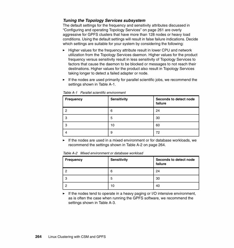
Tuning the Topology Services subsystemThe default settings for the frequency and sensitivity attributes discussed in “Configuring and operating Topology Services” on page 261 are overly aggressive for GPFS clusters that have more than 128 nodes or heavy load conditions. Using the default settings will result in false failure indications. Decide which settings are suitable for your system by considering the following:
� Higher values for the frequency attribute result in lower CPU and network utilization from the Topology Services daemon. Higher values for the product frequency versus sensitivity result in less sensitivity of Topology Services to factors that cause the daemon to be blocked or messages to not reach their destinations. Higher values for the product also result in Topology Services taking longer to detect a failed adapter or node.
� If the nodes are used primarily for parallel scientific jobs, we recommend the settings shown in Table A-1.
Table A-1 Parallel scientific environment
� If the nodes are used in a mixed environment or for database workloads, we recommend the settings shown in Table A-2 on page 264.
Table A-2 Mixed environment or database workload
� If the nodes tend to operate in a heavy paging or I/O intensive environment, as is often the case when running the GPFS software, we recommend the settings shown in Table A-3.
Frequency Sensitivity Seconds to detect node failure
2 6 24
3 5 30
3 10 60
4 9 72
Frequency Sensitivity Seconds to detect node failure
2 6 24
3 5 30
2 10 40
264 Linux Clustering with CSM and GPFS

Table A-3 Heavy paging or I/O environment
By default, Topology Services uses the settings shown in Table A-4.
Table A-4 Topology Services defaults
You can adjust the tunable attributes by using the cthatstune command. For example, to change the frequency attribute to the value 2 on network gpfs and then refresh the Topology Services subsystem, use the command:
cthatstune -f gpfs:2 -r
Refreshing the Topology Services daemonWhen your system configuration is changed (such as by adding or removing nodes or adapters), the Topology Services subsystem needs to be refreshed before it can recognize the new configuration.
To refresh the Topology Services subsystem, run either the cthatsctrl command or the cthatstune command, both with the -r option, on any node in the GPFS cluster.
Note that if there are nodes in the GPFS cluster that are unreachable with Topology Services active, they will not be refreshed. Also, if the connectivity problem is resolved such that Topology Services on that node is not restarted, the node refreshes itself to remove the old configuration. Otherwise, it will not acknowledge nodes or adapters that are part of the configuration.
Topology Services proceduresNormally, the Topology Services subsystem runs itself without requiring administrator intervention. On occasion, you might need to check the status of the subsystem. You can display the operational status of the Topology Services daemon by issuing the lssrc command.
Frequency Sensitivity Seconds to detect node failure
1 12 24
1 15 30
Frequency Sensitivity Seconds to detect node failure
1 4 8
Appendix A. SRC and RSCT 265

Topology Services monitors the Ethernet, the Myrinet switch, and the Token-Ring networks. To see the status of the networks, you need to run the command on a node that is up:
lssrc -ls cthats
In response, the lssrc command writes the status information to the standard output. The information includes:
� The information provided by the lssrc -s cthats command (short form).
� Six lines for each network for which this node has an adapter and includes the following information:
– The network name.
– The network index.
– The number of defined members: The number of adapters that the configuration reported existing for this network.
– The number of members: Number of adapters currently in the membership group.
– The state of the membership group, denoted by S (Stable), U (Unstable), or D (Disabled).
– Adapter ID: The address and instance number for the local adapter in this membership group.
– Group ID: The address and instance number of the membership group. The address of the membership group is also the address of the group leader.
– Adapter interface name.
– HB Interval, which corresponds to the Frequency attribute in the GPFS cluster data. This exists on a per network basis and has a default value that could be different.
– HB Sensitivity, which corresponds to the Sensitivity attribute in the GPFS cluster data. This exists on a per network basis and has a default value that could be different.
– Two lines of the network adapter statistics.
– The PID of the NIMs.
� The number of clients connected and the client process IDs and command names.
� Configuration instance: The instance number of the machines list file.
� Whether the daemon is working in a secure environment. If it is, the version number of the key used for mutual authentication is also included.
266 Linux Clustering with CSM and GPFS

� The segments pinned: NONE, a combination of TEXT, DATA, and STACK, or PROC.
� The size of text, static data, and dynamic data segments. Also, the number of outstanding memory allocations without a corresponding free memory operation.
� Whether the daemon is processing a refresh request.
� Daemon process CPU time, both in user and kernel modes.
� The number of page faults and the number of times the process has been swapped out.
� The number of nodes that are seen as reachable (up) from the local node and the number of nodes that are seen as not reachable (down).
� A list of nodes that are either up or down, whichever list is smaller. The list of nodes that are down includes only the nodes that are configured and have at least one adapter, which Topology Services monitors. Nodes are specified in the list using the format:
N1–N2(I1) N3–N4(I2)...
where N1 is the initial node in a range, N2 is the final node in a range, and I1 is the increment. For example, 5–9(2) specifies nodes 5, 7, and 9. If the increment is 1, then the increment is omitted. If the range has only one node, only the one node number is specified.
Example A-2 shows the output from the lssrc -ls cthats command on a node.
Example: A-2 lssrc -ls cthats output
[root@node001 root]# lssrc -ls cthatsSubsystem Group PID Status cthats cthats 1632 activeNetwork Name Indx Defd Mbrs St Adapter ID Group IDgpfs [ 0] 5 5 S 10.2.1.1 10.2.1.141gpfs [ 0] myri0 0x85b72fa4 0x85b82c56HB Interval = 1 secs. Sensitivity = 15 missed beatsMissed HBs: Total: 0 Current group: 0Packets sent : 194904 ICMP 0 Errors: 0 No mbuf: 0Packets received: 211334 ICMP 0 Dropped: 0NIM's PID: 1731gpfs2 [ 1] 5 5 S 10.0.3.1 10.0.3.141gpfs2 [ 1] eth0 0x85b72fa5 0x85b82c5aHB Interval = 1 secs. Sensitivity = 15 missed beatsMissed HBs: Total: 0 Current group: 0Packets sent : 194903 ICMP 0 Errors: 0 No mbuf: 0Packets received: 211337 ICMP 0 Dropped: 0NIM's PID: 1734 1 locally connected Client with PID:
Appendix A. SRC and RSCT 267

hagsd( 1749) Configuration Instance = 1035415331 Default: HB Interval = 1 secs. Sensitivity = 8 missed beats Daemon employs no security Segments pinned: Text Data Stack. Text segment size: 593 KB. Static data segment size: 628 KB. Dynamic data segment size: 937. Number of outstanding malloc: 383 User time 7 sec. System time 2 sec. Number of page faults: 844. Process swapped out 0 times. Number of nodes up: 5. Number of nodes down: 0.[root@node001 root]#
Group Services (GS) subsystemThe function of the Group Services subsystem is to provide other subsystems with a distributed coordination and synchronization service. Other subsystems that utilize or depend upon Group Services are called client subsystems. Each client subsystem forms one or more groups by having its processes connect to the Group Services subsystem and use the various Group Services interfaces. A process of a client subsystem is called a GS client.
A group consists of two pieces of information:
� The list of processes that have joined the group, called the group membership list
� A client-specified group state value
Group Services guarantees that all processes that are members of a group see the same values for the group information, and that they see all changes to the group information in the correct order. In addition, the processes may initiate changes to the group information via certain protocols that are controlled by Group Services.
A GS client that has joined a group is called a provider. A GS client that wants only to monitor a group without being able to initiate changes in the group is called a subscriber.
Once a GS client has initialized its connection to Group Services, it can join a group and become a provider. All other GS clients that have already joined the group (those that have already become providers) are notified as part of the join protocol about the new providers that want to join. The existing providers can either accept new joiners unconditionally (by establishing a one-phase join protocol) or vote on the protocol (by establishing an n-phase protocol). During the vote, they can choose to approve the request and accept the new provider into the group, or reject the request and refuse to allow the new provider to join.
268 Linux Clustering with CSM and GPFS

Group Services monitors the status of all the processes that are members of a group. If either the processes or the node on which a process is executing fails, Group Services initiates a failure notification that informs the remaining providers in the group that one or more providers have been lost.
Join and failure protocols are used to modify the membership list of the group. Any provider in the group may also propose protocols to modify the state value of the group. All protocols are either unconditional (one-phase) protocols, which are automatically approved, or conditional (n-phase) (sometimes called votes on) protocols, which are voted on by the providers.
During each phase of an n-phase protocol, each provider can take application-specific action and must vote to approve, reject, or continue the protocol. The protocol completes when it is either approved (the proposed changes become established in the group), or rejected (the proposed changes are dropped).
Group Services componentsThe Group Services subsystem consists of the following components:
� Group Services daemon
This daemon (hagsd) runs on each GPFS cluster node and is the central component of the Group Services subsystem.
� Group Services Application Program Interface (GSAPI)
This is the application programming interface that GS clients use to obtain the services of the Group Services subsystem. These API calls are used by both the CSM and GPFS products.
� Ports
The Group Services subsystem uses several types of communication:
– User Datagram Protocol (UDP) port numbers for intra-domain communications. That is, communications between Group Services daemons within an operational domain that is defined within the cluster.
The port used to communicate between nodes can be found in the /etc/services file (see the cthags tag).
– UNIX domain sockets for communications between GS clients and the local Group Services daemon (via the GSAPI).
� Control command
The control command is used to add the Group Services subsystem to the cluster. It can also be used to remove, start, or stop the subsystem from the cluster.
� Files and directories
Appendix A. SRC and RSCT 269

The Group Services subsystem uses the /var/ct directory to store files.
Group Services dependenciesThe Group Services subsystem depends on the following resources:
� System Resource Controller
A subsystem that can be used to define and control other subsystems. For more information, see “System Resource Controller (SRC)” on page 254.
� Cluster data
The cluster data contains the system configuration information, such as host names and MAC addresses. These data are used by GPFS or CSM commands to be able to contact cluster nodes. A GPFS cluster has a primary server, which is in charge of maintaining this data and may have a secondary server as a backup. These nodes are designated during the GPFS cluster creation. CSM stores the cluster data on the management server.
� Topology Services
A subsystem that is used to determine which nodes in a system are running at any given time. Group Services requests information such as adapter status and node connectivity from the Topology Services subsystem in order to make these information available to its clients. Details on how the Topology Services subsystem provides such information have been provided in “Topology Services subsystem” on page 257.
Configuring and operating Group ServicesThe following sections describe the various aspects of configuring and operating Group Services.
Group Services subsystem configurationGroup Services subsystem configuration is performed by the cthagscrtl command, which is included in the RSCT package.
The cthagsctrl command provides a number of functions for controlling the operation of the Group Services subsystem. These are:
� Add (configure) the Group Services subsystem
When the cthagsctrl command is used to add the Group Services subsystem, it first fetches the port number from the GPFS cluster data. Then it adds the Group Services daemon to the SRC using the mkssys command.
� Start and Stop the Group Services subsystem
The start and stop functions of the cthagsctrl command run the startsrc and stoprsc commands, respectively.
270 Linux Clustering with CSM and GPFS
� Delete (unconfigure) the Group Services subsystem
The delete function of the cthagsctrl command removes the subsystem from the SRC and removes the Group Services daemon communications port number from the /etc/services file. It does not remove anything from the GPFS cluster data because the Group Services subsystem may still be configured on other nodes in the operational domain.
� Turn tracing of the Group Services daemon on or off
The tracing function of the cthagsctrl command is provided to supply additional problem determination information when it is required by the IBM Support Center. Normally, tracing should not be turned on, because it might slightly degrade Group Services subsystem performance and can consume large amounts of disk space in the /var file system.
Initializing the Group Services daemonIn a normal condition, the Group Service daemon is started by GPFS. If necessary, the Group Services daemon can be started using the cthagsctrl command or the startsrc command directly.
During initialization, the Group Services daemon performs the following steps:
� It retrieves the number of the node on which it is running.
� It tries to connect to the Topology Services subsystem. If the connection cannot be established because the Topology Services subsystem is not running, it is scheduled to be retried periodically. This continues until the connection to Topology Services is established. Until the connection, the Group Services daemon writes an error log entry periodically and no clients may connect to the Group Services subsystem.
� It performs actions that are necessary to become a daemon. This includes establishing communications with the SRC subsystem so that it can return status in response to SRC commands.
� It establishes the Group Services domain, which is the set of nodes in the GPFS cluster. At this point, one of the GPFS daemons establishes itself as the GS name server. Until the domain is established, no GS client requests to join or subscribe to groups are processed. The GS name server is responsible for keeping track of all client groups that are created in the domain. To ensure that only one node becomes a GS name server, Group Services uses the following protocol:
a. When the daemon is connected to the Topology Services subsystem, it waits for Topology Services to tell it which nodes are currently running.
b. Based on the input from Topology Services, each daemon finds the lowest numbered running node in the domain. The daemon compares its own
Appendix A. SRC and RSCT 271

node number to the lowest numbered node and performs one of the following:
• If the node the daemon is on is the lowest numbered node, the daemon waits for all other running nodes to nominate it as the GS name server.
• If the node the daemon is on is not the lowest numbered node, it sends a nomination message to the lowest numbered node periodically, initially every five seconds.
c. Once all running nodes have nominated the GS name server and a coronation timer (about 20 seconds) has expired, the nominee sends an insert message to the nodes. All nodes must acknowledge this message. When they do, the nominee becomes the established GS name server and it sends a commit message to all of the nodes.
d. At this point, the Group Services domain is established and requests by clients to join or subscribe to groups are processed
� It enters the main control loop. In this loop, the Group Services daemon waits for requests from GS clients, messages from other Group Services daemons, messages from the Topology Services subsystem, and requests from the SRC for status.
Group Services daemon operationNormal operation of the Group Services subsystem requires no administrative intervention. The subsystem normally automatically recovers from temporary failures, such as node failures or failures of Group Services daemons. However, there are some operational characteristics that might be of interest to administrators:
� The maximum number of groups to which a GS client can subscribe or that a GS client can join is equivalent to the largest value containable in a signed integer variable.
� The maximum number of groups allowed within a domain is 65535.
� These limits are the theoretical maximum limits. In practice, the amount of memory available to the Group Services daemon and its clients will reduce the limits to smaller values.
On occasion, you may need to check the status of the subsystem. You can display the operational status of the Group Services daemon by issuing the lssrc command, as shown in Example A-3.
Example: A-3 Verify that Group Services is running
[root@storage001 root]# lssrc -ls cthagsSubsystem Group PID Status cthags cthags 2772 active1 locally-connected clients. Their PIDs:
272 Linux Clustering with CSM and GPFS

3223(mmfsd)HA Group Services domain information:Domain established by node 1Number of groups known locally: 3 Number of Number of localGroup name providers providers/subscribersGpfsRec.1 5 1 0Gpfs.1 5 1 0NsdGpfs.1 5 1 0[root@storage001 root]#
Appendix A. SRC and RSCT 273

274 Linux Clustering with CSM and GPFS

Appendix B. Common facilities
This appendix describes some common facilities that are used by CSM and GPFS products that may require special considerations when configuring your Linux cluster environment. These include:
� Domain Name Server (DNS)
� OpenSSH
B
© Copyright IBM Corp. 2002, 2004 275

DNS serverThis section provides basic information on how to set up a DNS server in CSM and GPFS installations. This section is not a complete reference for DNS, but rather covers those issues specific to these environments. Refer to DNS-specific documentation for further details.
Package descriptionBerkeley Internet Name Domain (BIND) is an implementation of the Domain Name System (DNS). The latest version can be found on the Internet Software Consortium (ISC) Web site at http://www.isc.org/products/BIND. It is an openly redistributable reference of the major components of the Domain Name System. It includes:
� A Domain Name System server� A Domain Name System resolver library� Tools to verify the proper operation of the DNS server
At the writing of this book, the latest version of BIND is Version 9.2.0.
DNS installationYou can directly compile the source code from ISC, or you can simply use the BIND package present on the Red Hat CD-ROM. To install the RPM, mount your Red Hat CD-ROM and install these two packages:
� # rpm -ivh bind-9.1.0-10.i386.rpm� # rpm -ivh bind-utils-9.1.0-10.i386.rpm
DNS configurationTo configure the DNS, edit the /etc/named.conf file. This file is composed of two parts. The first part refers to the general configuration parameters for the DNS server, like the directory where DNS zone configuration files are stored or the IP of the DNS servers to forward requests that cannot be resolved locally. The second part defines the zones for which the DNS server is authoritative (zones for which this DNS server acts as a primary or secondary server). For example:
� 0.0.127.in-addr.arpa.zone is for reverse localhost DNS resolution (127.0.0.0 subnet).
� 1.168.192.in-addr.arpa.zone is for our reverse network DNS resolution (192.168.1.0 subnet).
� localhost.zone is for the direct localhost DNS resolution.
276 Linux Clustering with CSM and GPFS

� clus-lab.austin.ibm.com.zone is for our domain DNS resolution.
Example B-1 shows you the zones we have defined in our labs.
Example: B-1 DNS zones - /etc/named.conf
options { directory "/var/named/"; forwarders { 9.3.199.2; 9.53.248.2; 9.53.249.2; }; allow-query { 192.168.1.0/24;}; allow-recursion { 192.168.1.0/24;}; transfer-format one-answer;};
zone "0.0.127.in-addr.arpa" { type master; file "0.0.127.in-addr.arpa.zone"; allow-update { none;};};
zone "1.168.192.in-addr.arpa" { type master; file "1.168.192.in-addr.arpa.zone"; allow-update { none;};};
zone "localhost" { type master; file "localhost.zone"; allow-update { none;};};
zone "clus-lab.austin.ibm.com" { type master; file "clus-lab.austin.ibm.com.zone"; allow-update { none;};};
Once your /etc/named.conf file is correct, create your zone files in /var/named/.
Example B-2 on page 279 shows the DNS configuration used in our labs.
� The $TTL 86400 text in the first line defines the time-to-live of the resource records in the zone for entries where the time-to-live is not explicitly defined.
Appendix B. Common facilities 277

� The second line defines the resource record (RR) Start of Authority (SOA) for the zone. The @ symbol is a reference to the zone name, and root.localhost describes the administrative contact for the zone, where the first dot (.) in the left should be exchanged by an @ to define the e-mail address. The numbers defined between the parenthesis, usually written one per line for better readability, define the following parameters: serial number of this zone file, refresh time, retry time (for failed refresh requests), expiration time, and minimum time-to-live for all entries in the zone.
� The next line defines an IN NS resource record. Since there is indication as to what RR this is associated with, the system uses the last used, the zone itself. In this case, IN NS defines the IP addresses of the name servers for the zone.
� The RR IN MX xx defines the different mail exchangers for the domain and their priority.
� The next entries are IN A records, defining the IP address for a name (real host name of the host).
� The RR IN CNAME defines the canonical name (alias) given to a host. For example, ftp.clus-labs.austin.ibm.com is an alias of the master.clus-labs.austin.ibm.com host.
Considerations when creating a zone fileThe following is some basic information that should help you when creating your own zone files for internal domains. This is regarding references to other host names and how to use the serial numbers in the SOA resource record.
Serial numbersThe serial numbers defined in the SOA resource record for each zone are used for secondary servers to check if the zone has been changed. For that reason, every time a zone file has been changed, the serial number must change also. To ease management, there are some patterns that can be used for serial numbers. One example is to create the serial numbers using the date of the last change in the file: YYYYMMDD##, where YYYY is the current year, MM the current month, DD the current day, and ## the sequence of changes. Every time you change this file, this serial number should be changed to reflect the date. If the last change occurred days before, just change the date and set ## to 01. If the last change occurred today, just add one to ##.
References to other host namesYou can define NS, MX, or any other RR referring to names, but you should take care of how you write the names. If the referenced name is in this same zone, you could write only the host name of the system, as defined in its IN A record. If the referenced host is in another zone, wherever it is, you should use its IP address or FDQN (Fully Qualified Domain Name). That is, its full host name,
278 Linux Clustering with CSM and GPFS

including its domain names and a dot (.) in the end of the name, like headnode.clus-lab.austin.ibm.com.
Example B-2 contains an example of the zone files that we used in our lab environment.
Example: B-2 DNS zone files
File /var/named/clus-labs.austin.ibm.com.zone
$TTL 86400@ IN SOA headnode.clus-lab.austin.ibm.com root.headnode.clus-labs.austin.ibm.com ( 4 ; serial 28800 ; refresh 7200 ; retry 604800 ; expire 86400 ; minimum )
; IP addresses of DNS servers for this zone; NS means Name Server IN NS 192.168.1.100; Mail server IN MX 10 master
; Addresses recordsclsnode1 IN A 192.168.1.201clsnode2 IN A 192.168.1.202clsnode3 IN A 192.168.1.203clsnode4 IN A 192.168.1.204master IN A 192.168.1.100mgtnode4 IN A 192.168.1.154consesp1 IN A 192.168.1.155
; Canonical names definitionsheadnode IN CNAME mastermail IN CNAME masterftp IN CNAME master
File /var/named/1.168.192.in-addr.arpa.zone
$TTL 86400@ IN SOA headnode.clus-lab.austin.ibm.com root.headnode.clus-labs.austin.ibm.com ( 2 ; serial 28800 ; refresh
Appendix B. Common facilities 279

7200 ; retry 604800 ; expire 86400 ; minimum )
IN NS 192.168.1.100
100 IN PTR master.clus-lab.austin.ibm.com.201 IN PTR clsnode1.clus-lab.austin.ibm.com.202 IN PTR clsnode2.clus-lab.austin.ibm.com.203 IN PTR clsnode3.clus-lab.austin.ibm.com.204 IN PTR clsnode4.clus-lab.austin.ibm.com.
Starting the DNS serverOnce your DNS zone files are created, you can start the DNS server and set it to be startable at boot time:
[root@master /root]# /etc/rc.d/init.d/named startStarting named: [ OK ][root@master /root]# chkconfig named on
You can verify that no errors occurred by inspecting the file /var/log/messages:
# tail -f /var/log/message
Nov 29 19:58:43 master named: named startup succeededNov 29 19:58:43 master named[7620]: starting BIND 9.1.0 -u namedNov 29 19:58:43 master named[7620]: using 1 CPUNov 29 19:58:43 master named[7624]: loading configuration from '/etc/named.conf'Nov 29 19:58:43 master named[7624]: the default for the 'auth-nxdomain' option is now 'no'Nov 29 19:58:43 master named[7624]: no IPv6 interfaces foundNov 29 19:58:43 master named[7624]: listening on IPv4 interface lo, 127.0.0.1#53Nov 29 19:58:43 master named[7624]: listening on IPv4 interface eth0, 192.168.1.100#53Nov 29 19:58:43 master named[7624]: dns_master_load: csm-labs.austin.ibm.com.zone:29: ignoring out-of-zone dataNov 29 19:58:43 master named[7624]: running
A mistake in the configuration file or zone files will prevent named from loading the file and that may be not easy to track. In that case, you may start the daemon using the -d # option (debug), where # is the debug level. When run with this option, named will create a debug file named named.run in the current directory with the required debug level.
280 Linux Clustering with CSM and GPFS

Testing the DNS serverThe best way to test a name server is to use programs like dig, nslookup, or host.
digThe syntax of this command is:
dig @server domain query-type query-class
For example:
[root@master /root]# dig @localhost clus-lab.austin.ibm.com ns
; <<>> DiG 9.1.0 <<>> @localhost clus-lab.austin.ibm.com ns;; global options: printcmd;; Got answer:;; ->>HEADER<<- opcode: QUERY, status: NOERROR, id: 7457;; flags: qr aa rd ra; QUERY: 1, ANSWER: 1, AUTHORITY: 0, ADDITIONAL: 0
;; QUESTION SECTION:;clus-lab.austin.ibm.com. IN NS
;; ANSWER SECTION:clus-lab.austin.ibm.com. 86400 IN NS 192.168.1.100.clus-lab.austin.ibm.com.
;; Query time: 1 msec;; SERVER: 127.0.0.1#53(localhost);; WHEN: Wed Dec 5 23:42:55 2001;; MSG SIZE rcvd: 69
[root@master /root]#[root@master /root]# dig @localhost . ns
; <<>> DiG 9.1.0 <<>> @localhost . ns;; global options: printcmd;; Got answer:;; ->>HEADER<<- opcode: QUERY, status: NOERROR, id: 7780;; flags: qr rd ra; QUERY: 1, ANSWER: 13, AUTHORITY: 0, ADDITIONAL: 13
;; QUESTION SECTION:;. IN NS
;; ANSWER SECTION:. 191030 IN NS M.ROOT-SERVERS.NET.. 191030 IN NS A.ROOT-SERVERS.NET.. 191030 IN NS B.ROOT-SERVERS.NET.. 191030 IN NS C.ROOT-SERVERS.NET.
Appendix B. Common facilities 281

. 191030 IN NS D.ROOT-SERVERS.NET.
. 191030 IN NS E.ROOT-SERVERS.NET.
. 191030 IN NS F.ROOT-SERVERS.NET.
. 191030 IN NS G.ROOT-SERVERS.NET.
. 191030 IN NS H.ROOT-SERVERS.NET.
. 191030 IN NS I.ROOT-SERVERS.NET.
. 191030 IN NS J.ROOT-SERVERS.NET.
. 191030 IN NS K.ROOT-SERVERS.NET.
. 191030 IN NS L.ROOT-SERVERS.NET.
;; ADDITIONAL SECTION:A.ROOT-SERVERS.NET. 364083 IN A 198.41.0.4B.ROOT-SERVERS.NET. 364083 IN A 128.9.0.107C.ROOT-SERVERS.NET. 364083 IN A 192.33.4.12D.ROOT-SERVERS.NET. 364083 IN A 128.8.10.90E.ROOT-SERVERS.NET. 364083 IN A 192.203.230.10F.ROOT-SERVERS.NET. 364083 IN A 192.5.5.241G.ROOT-SERVERS.NET. 364083 IN A 192.112.36.4H.ROOT-SERVERS.NET. 364083 IN A 128.63.2.53I.ROOT-SERVERS.NET. 364083 IN A 192.36.148.17J.ROOT-SERVERS.NET. 364083 IN A 198.41.0.10K.ROOT-SERVERS.NET. 364083 IN A 193.0.14.129L.ROOT-SERVERS.NET. 364083 IN A 198.32.64.12M.ROOT-SERVERS.NET. 364083 IN A 202.12.27.33
;; Query time: 2 msec;; SERVER: 127.0.0.1#53(localhost);; WHEN: Wed Dec 5 23:43:21 2001;; MSG SIZE rcvd: 436
[root@master /root]#
nslookupAn example of nslookup follows:
[root@master named]# nslookup -sil> clsnode1Server: 192.168.1.100Address: 192.168.1.100#53
Name: clsnode1.csm-labs.austin.ibm.comAddress: 192.168.1.201> ftpServer: 192.168.1.100Address: 192.168.1.100#53
ftp.csm-labs.austin.ibm.com canonical name = master.csm-labs.austin.ibm.com.Name: master.csm-labs.austin.ibm.com
282 Linux Clustering with CSM and GPFS

Address: 192.168.1.100> 192.168.1.202Server: 192.168.1.100Address: 192.168.1.100#53
202.1.168.192.in-addr.arpa name = clsnode2.csm-labs.austin.ibm.com.
hostAn example of host follows:
[root@master named]# host mastermaster.csm-labs.austin.ibm.com. has address 192.168.1.100[root@master named]# host mailmail.csm-labs.austin.ibm.com. is an alias for master.csm-labs.austin.ibm.com.master.csm-labs.austin.ibm.com. has address 192.168.1.100[root@master named]#
BIND loggingBIND is able to create detailed logging about its use, queries, security problems, violation attempts, and many other things. A simple logging configuration that would split its records in four different files in /var/log/bind can be found in Example B-3. This sample configuration should be placed in the /etc/named.conf file in the main section. Basically, it creates four different logging channels (config, critic, secure, and other), one for each log file, and then attaches DNS events to one of the logging channels. Some events are also being directed to the preexisting channel null.
Example: B-3 BIND logging example
logging {
channel config {
Note: The second example of dig gets all the name server (NS) records for domain . (dot). This domain (.) is the root domain of the entire DNS infrastructure, and those are the servers that are constantly asked about .com, .edu, .us, .fr, .br, and all top level domains. The output of this example is exactly the root.db or cache.db file defined in /etc/named.conf, defining the root servers for DNS. These entries do not change very often, but it is very common to add entries in the crontabs file of DNS servers to update their DNS root servers from time to time, by issuing the exact command used in the example and directing its output to the root.db file. But because the DNS server used in our examples does have forward servers, it will not do resolution using the root servers, and its configuration in /var/named.conf does not have an entry for the zone.
Appendix B. Common facilities 283

file "/var/log/bind/config"; severity debug; print-category yes; print-severity yes; print-time yes; }; channel critic { file "/var/log/bind/critic"; severity debug; print-category yes; print-severity yes; print-time yes; }; channel secure { file "/var/log/bind/secure"; severity debug; print-category yes; print-severity yes; print-time yes; };channel other { file "/var/log/bind/other"; severity debug; print-category yes; print-severity yes; print-time yes; }; category config { config; }; category security { secure; }; category xfer-in { other; }; category xfer-out { other; }; category update { other; }; // Don't want these messages category lame-servers { null; }; category notify { null; }; category queries { null; };};
Other featuresBIND has many other features that may be useful in cluster environments, but that are not covered in this redbook. If you need more information, we suggest you reference the Linux Documentation Project Web site at:
http://www.linuxdoc.org
284 Linux Clustering with CSM and GPFS
OpenSSHThis section provides information on how to configure nodes to run a secure shell (SSH) environment in a way that ssh and scp commands can replace the use of rsh and rcp for CSM and GPFS.
Package descriptionOpenSSH is the open-source implementation of the IEEE SSH protocol version 1 and 2. The Institute of Electrical and Electronics Engineers, Inc. (IEEE) is a non-profit, technical professional association. For more information about the IEEE (known as Eye-triple-E) can be found at the following Web site:
http://www.ieee.org/
OpenSSH is provided under Berkeley Software Distribution (BSD) license. For more information about the BSD license, refer to the following Web site:
http://www.openbsd.org
The RPM package includes the clients for ssh, scp, and sftp, as well as the sshd server and many local applications like ssh-keygen, ssh-add, ssh-agent, and sftp-server.
OpenSSH authentication methodsApart from keeping all communication encrypted during network transmission, SSH can provide stronger authentication methods, and in situations where non-password logins are needed, it can increase the security level for those transactions.
The SSH protocol Version 2 uses two different kinds of authentication: public key and password authentication. Because CSM and GPFS need all nodes to communicate to each other using non-password logins, the first method will be
Note: This section does not intend to provide information on how to configure SSH to run in the most secure way, but to provide information on how it can be configured so CSM and GPFS can utilize it.
Attention: Tests using ssh and rsh commands have shown some performance issues with the secure shell. Also, comparing scp and rcp commands in a cluster presented performance differences. So, before installing SSH, make sure your environment requires the secure shell service.
Appendix B. Common facilities 285

used, and this section provides you with information on how to prepare SSH for this situation.
Update the file /etc/hostsIn order to ease key and host names management, we suggest that you include all nodes in the /etc/hosts file, as in Example B-4.
Example: B-4 /etc/hosts file
127.0.0.1 localhost.localdomain localhost10.0.0.1 masternode.cluster.com masternode10.0.0.2 node001.cluster.com node00110.0.0.3 node002.cluster.com node002
Key generation for the root userThere are many ways to permit non-password login from one host to other hosts. For our situation, we generate a pair of keys for the root user on each node and exchange them.
The first step is to generate the keys themselves. This procedure will produce two files for each node: id_rsa that holds the private keys and id_rsa.pub that holds the public key.
Example B-5 shows the creation of a key pair using a null password. It is very important that the password for the key is null so there will not be any password prompt for the connection to be established. This is achieved by the use of the -N "" option.
Example: B-5 Key generation
# ssh-keygen -t rsa -N ""Generating public/private rsa key pair.Enter file in which to save the key (/root/.ssh/id_rsa):Your identification has been saved in /root/.ssh/id_rsa.Your public key has been saved in /root/.ssh/id_rsa.pub.The key fingerprint is:a6:c4:e5:02:7b:a0:3f:4b:58:e2:52:4b:05:ec:34:b5 root@masternode
Important: Ensure that no host name other than localhost will be assigned to the 127.0.0.1 address.
286 Linux Clustering with CSM and GPFS

Generation of authorized_keys fileWhen you try to log on to a host using public key authentication, a basic public key signing procedure is used to authenticate the user and grant access to the system. The SSH client signs a session identifier and sends the result to the server. The server will verify whether the signature is correct using the user’s pre-stored public key in the $HOME/.ssh/authorized_keys file. If the signature is correct, access is granted. If not, or if the public key was not found in the authorized_keys file, the server will try the next authentication method.
To create the authorized_keys file, you must copy the public keys from the root user on all nodes to the authorized_keys file on a single node (the local node in Example B-6). It is very important that all keys are copied into the file, even the public key of the host where the file is being created.
Example: B-6 Creating the authorized_keys file
# cd /root/.ssh# cat id_rsa.pub >> authorized_keys# ssh node001 cat .ssh/id_rsa.pub >> authorized_keysroot@node001's password:# ssh node002 cat .ssh/id_rsa.pub >> authorized_keysroot@node002's password:
Distribution of the authorized_keys file to the other nodesCopying the authorized_keys file generated in the last step to the other hosts will allow the root user on every node to log on to every other node without having to provide a password (see Example B-7).
Example: B-7 Distributing the authorized_keys file
# cd /root/.ssh# scp authorized_keys node001:.ssh/root@node001's password:authorized_keys 100% |*****************************| 711 00:00# scp authorized_keys node002:.ssh/root@node002's password:authorized_keys 100% |*****************************| 711 00:00
After copying the file, any valid login attempt will be done without a password prompt.
Appendix B. Common facilities 287

Ensuring all nodes know each otherSSH has some methods to ensure that the host you are connecting to really is the node you are trying to connect to. This may seem unnecessary, but it is very useful to prevent the man-in-the-middle attack.
When you install the SSH server on a node, you must create the host key pair for the server where the public key will be stored by the clients in the known_hosts file. When the SSH client connects again to the server, the client verifies whether the private key used by the server matches the public key stored in the known_hosts file. If it matches, it means that the private key has not been changed and the server you are connecting to really is the server you wanted to connect to. When the SSH client verifies the key has been changed, it will issue a warning to the user, as in Example B-8. Depending on the SSH configuration, the user will be able (or not) to confirm that the key has changed and connected to the server anyway. If the client does not permit the override of the alarm, the user will have to edit the known_hosts file and change (or delete) the key manually.
Example: B-8 Server verification
# ssh node001@@@@@@@@@@@@@@@@@@@@@@@@@@@@@@@@@@@@@@@@@@@@@@@@@@@@@@@@@@@@ WARNING: REMOTE HOST IDENTIFICATION HAS CHANGED! @@@@@@@@@@@@@@@@@@@@@@@@@@@@@@@@@@@@@@@@@@@@@@@@@@@@@@@@@@@@IT IS POSSIBLE THAT SOMEONE IS DOING SOMETHING NASTY!Someone could be eavesdropping on you right now (man-in-the-middle attack)!It is also possible that the RSA host key has just been changed.The fingerprint for the RSA key sent by the remote host isc9:7e:7b:b6:fc:54:b7:92:98:df:73:4f:6c:fc:39:60.Please contact your system administrator.Add correct host key in /root/.ssh/known_hosts to get rid of this message.Offending key in /root/.ssh/known_hosts:3RSA host key for node001 has changed and you have requested strict checking.
When an SSH connection is made to a host whose key is not in the known_hosts file, the client will ask the user to confirm the server key and identification, as shown in Example B-9 on page 289.
Note: The man-in-the-middle attack is done by replacing the server, changing the network routing, or placing a fake server between the client and the real server in a way that when clients try to connect to the server, they connect actually on the false server, pretending to be the real one.
288 Linux Clustering with CSM and GPFS

Example: B-9 Confirm server key and identification
# ssh node001The authenticity of host 'node001 (10.0.0.1)' can't be established.RSA key fingerprint is 1d:a9:d8:9b:f7:9d:fa:41:c9:ce:32:9b:14:00:b2:e3.Are you sure you want to continue connecting (yes/no)?
This situation requires user interaction (type yes to confirm the server key) for the logon process to continue. If that happens during CSM or GPFS installation, the installation process will fail.
It is very important that you ensure that all nodes know each other. This can be done by using the master node, for example, to connect to all nodes (including itself) and then copying the master node’s known_hosts file to all other nodes.
Example B-10 shows the process of creating the known_hosts file and replicating it to the other nodes.
Example: B-10 Creating and replicating known_hosts file
# ssh node001The authenticity of host 'node001 (10.0.0.1)' can't be established.RSA key fingerprint is 1d:a9:d8:9b:f7:9d:fa:41:c9:ce:32:9b:14:00:b2:e3.Are you sure you want to continue connecting (yes/no)? yesWarning: Permanently added 'node001,10.0.0.1' (RSA) to the list of known hosts.Last login: Thu Oct 31 16:20:00 2002 from masternode[root@node001 /root]# exitlogoutConnection to node001 closed.
# ssh node002The authenticity of host 'node002 (10.0.0.2)' can't be established.RSA key fingerprint is bb:ea:56:05:5d:e4:66:08:bb:66:70:10:6d:9d:0f:4b.Are you sure you want to continue connecting (yes/no)? yesWarning: Permanently added 'node02,10.0.0.2' (RSA) to the list of known hosts.Last login: Thu Oct 31 16:20:00 2002 from masternode[root@node002 /root]# exitlogoutConnection to node002 closed.
# scp .ssh/known_hosts node001:.ssh/known_hosts 100% |*****************************| 907 00:00# scp .ssh/known_hosts node02:.ssh/known_hosts 100% |*****************************| 907 00:00
We must remember also that SSH ties the key to the host name used in the connection. So if you already have the key for the host node001, and you try to connect to the same host using its Fully Qualified Domain Name (FQDN), SSH
Appendix B. Common facilities 289

will ask you again to confirm the key for the new host name. If your cluster may use both names (host name and FQDN), be sure to populate the known_hosts file with both names for all hosts.
If you want to avoid the user interaction on the first SSH call, you can set the following parameter in the /etc/ssh/ssh_config file:
StrictHostKeyChecking no
With this setting, you do not need to make any user interactions and the known_hosts file will automatically be updated. Warning messages will be included in the /var/log/messages log file.
Verification of the SSH configurationIn order not to have problems during CSM and GPFS installation using ssh and scp commands, we suggest that you run a few tests to ensure your SSH configuration is adequate for these systems to run.
The main requirement for CSM and GPFS regarding remote copy and remote shell connectivity is the possibility of one node to execute commands and transfer files to other nodes without having to provide any password. One way way to test this is to verify that no password is being asked for when you run ssh on every node connecting to every other node, including itself.
Additional information and trouble shootingFor more information on OpenSSH, access:
http://www.openssh.org/
For trouble-shooting information, access the OpenSSH Frequently Asked Questions (FAQ) and/or the mailing lists archive links on the home page.
290 Linux Clustering with CSM and GPFS

Appendix C. Migrating to GPFS 1.3 from earlier versions
This appendix provides the steps to migrate to GPFS Version 1.3 from earlier versions of GPFS.
C
© Copyright IBM Corp. 2002, 2004 291

Migration stepsAll nodes in a GPFS fileset must be running the same level of GPFS. If you want to test the newer revision of GPFS on a small subset of your cluster before installing it on the bulk of the nodes, you must remove some nodes from the GPFS nodeset. Details of how to do this are in the IBM General Parallel File System for Linux: Concepts, Planning, and Installation Guide, GA22-7844, although the procedure is a little involved. A potentially simpler approach is to install a small isolated cluster for testing. Here we cover simply the main migration of a cluster.
To upgrade GPFS on an entire cluster:
1. Shut down GPFS on all the nodes.
GPFS cannot be running on the nodes when the software is updated.
Ensure no applications are running that access GPFS, un-export any NFS exported GPFS file systems, and then run, from the GPFS primary node:
# mmshutdown -a
This will shut down GPFS on all the nodes in your GPFS cluster.
2. Install the new level of code.
Section 7.4.1, “Installing the source files” on page 205 details the procedure for installing GPFS RPMs with SMS. This same procedure can be used to upgrade the nodes to a later revision of code. The basic steps are:
a. Copy all GPFS and bundled RSCT RPMs to /csminstall/Linux/RedHat/7.3/i386/RedHat/updates.
b. Run cd /csminstall/Linux/RedHat/7.3/i386/RedHat/updates.
c. Use smsupdatenode to install the new versions of the code. Ensure that your gpfs wildcard only include the very latest release, for example:
# smsupdatenode -ai gpfs*1.3.0-0* rsct*2.3.0.10-0*
If the wildcard expand to multiple levels (1.3.0-0 and 1.3.0-1, for example), the smsupdatenode will fail.
3. Re-build and re-distribute the GPFS portability layer.
Although the GPFS portability layer source code (gpfs.gpl.*) need not be installed on all the nodes in the cluster, the binary modules built from it must.
Before installing the new modules, we recommend that the ones from the previous version are backed up, in case you want to revert back to the old
Note: If you are changing kernel versions as well as GPFS levels, it is strongly recommend that you perform at least rudimentary testing.
292 Linux Clustering with CSM and GPFS

level of code. The files are mmfslinux, lxtrace, tracedev and dumpconv, and are located in /usr/lpp/mmfs/bin; If you are using CFM to distribute these files, the master copies reside in /cfmroot/usr/lpp/mmfs/bin on the management node.
The procedure for building and distributing the portability layer is documented in 7.4.2, “Building the GPFS open source portability layer” on page 206.
If you are upgrading your Linux kernel at the same time as GPFS, be sure to build the portability layer (as well as additional drivers, such as gm) against the new version of the kernel source.
4. Start the new software.
In order to start the new version of GPFS, the newly built kernel modules must be loaded. In order to load the new modules, the old ones must first be unloaded. If possible, we recommend that this is performed with a reboot of all the nodes in the GPFS cluster; this allows GPFS startup on boot to be verified and provides a known clean starting point in the event of any problems.
If the nodes cannot be rebooted, run the following from the master node to unload the modules:
# dsh -av /sbin/rmmod mmfs mmfslinux tracedev
If this command fails, the nodes must be rebooted anyway.
If the nodes were not rebooted (or if GPFS is not configured to start on boot), start it by running the following command on the GPFS primary node:
# mmstartup -a
5. Verify the correct operation.
At this point, you should verify that GPFS is functioning correctly at the latest level. Check that the file systems mounted correctly and that you can perform normal file system operations (cd, ls, cat, and so on). Run a "real" job and ensure it runs correctly to completion.
6. Migrate the file system.
You may not be taking advantage of all the new features of your new version of GPFS until you migrate the file system format to the latest level. However, once you migrate the file system it becomes permanently incompatible with previous versions of GPFS. It is not recommended that you migrate immediately; instead, continue running without migration until you are satisfied that the new release operates correctly.
When you are ready, format migration can be performed by running the following command for each of your file systems:
# mmchfs -V <gpfsdevice>
Appendix C. Migrating to GPFS 1.3 from earlier versions 293

294 Linux Clustering with CSM and GPFS

Appendix D. Planning worksheets
This appendix includes sample worksheets used for planning both a CSM and GPFS installation. It includes:
� Management node TCP/IP attribute worksheet
� Compute node TCP/IP attribute worksheet
� Node attribute worksheet
� File system descriptions
� Network Shared Disk descriptions
D
© Copyright IBM Corp. 2002, 2004 295

CSM planning worksheetsThe following sections provide the planning worksheets for CSM.
Management node TCP/IP attributes worksheets
Hostname and domain
Hostname
Domain name
Gateway
DNS 1
DNS 2
DNS 3
Public VLAN
IP address
Subnet address
Cluster VLAN
IP address
Subnet address
Management VLAN
IP address
Subnet address
Other VLAN (Myrinet, Gigabit, and so on)
IP address
Subnet address
296 Linux Clustering with CSM and GPFS

Compute node TCP/IP attributes worksheet
Hostname IP address MAC address
Appendix D. Planning worksheets 297

Node attributes worksheets
Inst
allM
eth
od
H
WTy
pe
Co
nso
leP
ort
Nu
m
Co
nso
lem
eth
od
C
on
sole
serv
ern
um
ber
Co
nso
lese
rver
nam
e
HW
Co
ntr
ol
No
deI
d
Po
wer
met
ho
d
HW
Co
ntr
olP
oin
t H
ost
nam
e
298 Linux Clustering with CSM and GPFS

GPFS Planning worksheetsThe following sections provide the planning worksheets for GPFS.
File system descriptions
Inst
allP
KG
A
rch
itec
ture
Inst
all
Dis
trib
uti
on
Ver
sio
n
Inst
all
Dis
trib
uti
on
Nam
e
Inst
all
OS
Nam
e In
stal
l C
SM
Ver
sio
nH
ost
nam
e
File system Mount point NSDs Replicas
Appendix D. Planning worksheets 299

Network File Shared descriptions
Disk PVID NSD Holds D/M Primary server Secondary server
300 Linux Clustering with CSM and GPFS

Glossary
ASM Advanced Systems Management processor (also known as service processor) allows remote node power on/off/reset capability, monitors node environmental conditions, and allows remote POST/BIOS console, power management, and SNMP alerts.
Beowulf An approach to building a cluster of off-the-shelf commodity personal computers, interconnecting them with Ethernet, and running programs written for parallel processing.
Bootstrap Protocol (BOOTP) A protocol that allows a client to find both its Internet Protocol (IP) address and the name of a file from a network server.
cluster A loosely-coupled collection of independent systems (nodes) organized into a network for the purpose of sharing resources and communicating with each other.
Cluster Systems Management (CSM) A distributed system management solution for machines or nodes. With this software, an administrator can easily set up and maintain a system cluster by using functions like monitoring, hardware control, and configuration file management. Specifically, within the cluster, nodes can be added, removed, changed, or listed. Commands can be run across nodes or node groups in the cluster, and responses can be gathered. Nodes and applications can be monitored as to whether they are up or down, CPU, memory, and system utilization can be monitored, and automated responses can be run when events occur in the cluster. A single management server is the control point for the CSM cluster. Note that CSM manages a loose cluster of machines. It does not provide high availability services or fail-over technology, although high-availability clusters can be part of the set of machines that CSM is managing.
© Copyright IBM Corp. 2002, 2004. All rights reserved
disk descriptor Defines how a disk is to be used within a GPFS file system. This data is stored on the primary and secondary GPFS cluster data servers as defined in GPFS commands.
Domain Name System (DNS) A server program that supplies name-to-address conversion by mapping domain names to IP addresses. The domain name server allows users to request services of a computer by using a symbolic name, which is easier to remember than an IP address.
Dynamic Host Configuration Protocol (DHCP) An application-layer protocol that allows a machine on the network, the client, to get an IP address and other configuration parameters from the server.
High Availability (HA) clusters A system typically made up of two or more robust machines that mirror each other. Usually half the nodes are actively working, while the other half are quietly waiting to take over in case of a failure. HA cluster design varies according to its function.
High Performance Computing cluster (HPC cluster) A system designed for greater computational power than a single computer alone could provide. In the past, high-performance computing was typically reserved for the scientific community, but now it is breaking into the mainstream market. HPC is a field of computer science that focuses on developing supercomputers, parallel processing algorithms, and applications.
. 301

General Parallel File System (GPFS) Allows users shared access to files that may span multiple disk drives on multiple nodes. It offers many of the standard UNIX file system interfaces, allowing most applications to execute without modification or recompiling. GPFS also supports UNIX file system utilities, that is, users can continue to use the UNIX commands they have always used for ordinary file operations. The only commands unique to GFPS are those for administering the GPFS file system. GPFS provides file system services to parallel and serial applications. GPFS allows parallel applications simultaneous access to the same files, or different files, from any node in the GPFS nodeset, while managing a high level of control over all file system operations. GPFS is particularly appropriate in an environment where the aggregate peak need for data exceeds the capability of a distributed file system server.
GPFS cluster A subset of existing cluster nodes defined as being available for use by GPFS file systems. The GPFS cluster is created via GPFS commands. GPFS nodesets and file systems are subsequently created by other GPFS commands.
GPFS nodeset A GPFS nodeset is a group of nodes that all run the same level of GPFS code and operate on the same file systems. Users have the ability to define more than one GPFS nodeset in the same GPFS cluster.
Inter-Process Communication (IPC) The process by which programs communicate data to each other and synchronize their activities. Semaphores, signals, and internal message queues are common methods of interprocess communication.
KickStart Allows users to automate most of a Red Hat Linux installation. A system administrator can create a single file containing the answers to all the questions that would normally be asked during a typical Red Hat Linux installation.
Message Passing Interface (MPI) Message-passing standard that facilitates the development of parallel applications and libraries.
metadata Data structures that contain access information about file data. These might include inodes, indirect blocks, and directories. These data structures are used by GPFS but are not accessible to user applications.
mirroring The creation of a mirror image of data to be reserved in the event of disk failure.
Network File System (NFS) A distributed file system that allows users to access files and directories located on remote computers and to treat those files and directories as if they were local.
Network Shared Disk (NSD) A GPFS function that allows application programs executing at different nodes of a GPFS cluster to access a raw logical volume as if it were local at each of the nodes. In actuality, the logical volume is local at only one of the nodes, known as the server node.
open source Software that is developed and improved by a group of volunteers cooperating together on a network. Many parts of the UNIX operating system were developed this way, including Linux.
Preboot Execution Environment (PXE) Designed to define a standard set of preboot protocol services within a client, with the goal of allowing network-based booting to use industry-standard protocols.
PVM Portable message-passing programming system designed to link separate host machines to form a "virtual machine," which is a single, manageable computing resource.
PXELinux A SysLinux derivative for booting Linux off a network server using a network ROM conforming to PXE specifications.
RSA Remote Supervisor Adapter (also known as service processor) allows remote management similar to ASM. However, RSA provides additional functions over the ASM adapters. RSA is used with the new models like the Model 342.
302 Linux Clustering with CSM and GPFS

Red Hat Package Manager (RPM) A packaging system that allows users to package source code for new software into source and binary form such that binaries can be easily installed and tracked and source can be rebuilt easily.
Redundant Array of Independent Disks (RAID) A set of physical disks that act as a single physical volume and use parity checking to protect against disk failure.
Serial Storage Architecture (SSA) An expanded storage adapter for multi-processor data sharing in UNIX-based computing, allowing disk connection in a high-speed loop.
Simple Network Management Protocol (SNMP) A protocol governing network management and the monitoring of network devices and their functions.
small computer system interface (SCSI) An adapter supporting the attachment of various direct-access storage devices.
storage area network (SAN) The connectivity of multiple systems that attach to a single storage device.
SysLinux A boot loader for the Linux operating system that promises to simplify the Linux installation.
System Resource Controller (SRC) A set of commands and subroutines to make it easier for the system manager and programmer to create and control subsystems. A subsystem is any program or process or set of programs or processes that is usually capable of operating independently or with a controlling system.
Trivial File Transfer Protocol (TFTP) A set of conventions for transferring files between hosts using minimal protocol.
virtual file system (VFS) An abstraction of a physical file system implementation that provides a consistent interface to multiple file systems, both local and remote. This consistent interface allows the user to view the directory tree on the running system as a single entity even when the tree is made up of a number of diverse file system types.
VLAN Short for virtual LAN. A network of nodes that behave as if they were connected to the same cable even though they may actually be physically located on different segments of a LAN. VLANs are configured through software rather than hardware, which makes them extremely flexible.
virtual shared disk (VSD) A virtual component where nodes have access to remotely-mounted raw logical volumes.
Glossary 303

304 Linux Clustering with CSM and GPFS

acronyms
ACL Access Control List
APC American Power Conversion
API Application Program Interface
ASM Advanced System Management
ASMA Advanced System Management Adapter
BIND Berkeley Internet Name Domain
BIOS Basic Input Output System
BSD Berkeley Software Distribution
CE Customer Engineer
CFM Configuration File Manager
CSM Cluster Systems Management
DCEM Distributed Command Execution Manager
DHCP Dynamic Host Configuration Protocol
DMS Database and Distributed Management Server
DNS Domain Name System
DSA Digital Signature Algorithm
DSH Distributed Shell
ERRM Even Response Resource Manager
ESP Ethernet Serial Provider
FAQ Frequently Asked Questions
FQDN Fully Qualified Domain Name
Gb Gigabit
GB Gigabyte
GBIC GigaBit Interface Converter
GPFS General Parallel File System
GPS Global Positioning System
Abbreviations and
© Copyright IBM Corp. 2002, 2004. All rights reserved
GS Group Services
GSAPI Group Services Application Program Interface
GUI Graphical User Interface
HA High availability
IBM International Business Machines Corporation
IEEE Institute of Electrical and Electronics Engineers, Inc.
ISC Internet Software Consortium
ISO International Organization for Standardization
ITSO International Technical Support Organization
KVM Keyboard Video Mouse Switch
LKCD Linux Kernel Crash Dump
NFS Network File System
NIC Network Interface Card
NS Name Server
NSD Network Shared Disk
NTP Network Time Protocol
OEM Original Equipment Manufacturer
PCI Peripheral Component Interconnect
PCI Peripheral Computer Interface
PDU Power Distribution Unit
Perl Practical Extraction and Report Language
PID Process Identifier
POST Power-On Self-Test
PSSP Parallel System Support Programs
. 305

RAID Redundant Array of Independent Disks
RMC Resource Monitoring and Control
RPM Red Hat Package Manager
RR Resource Record
RSA Remote Supervisor Adapter
RSCT Reliable Scalable Cluster Technology
RSH Remote Shell
SCSI Small Computer System Interface
SNMP Simple Network Management Protocol
SOA Start of Authority
SPN Service Processor Network
SRC System Resource Controller
SSH Secure Shell
TB Terabyte
TCP Transmission Control Protocol
TFTP Trivial File Transfer Protocol
TTY Teletypewriter
UDP User Datagram Protocol
UPS Uninterruptible power supply
VFS Virtual File System
VLAN Virtual Local Area Network
WAN Wide Area Network
306 Linux Clustering with CSM and GPFS

Related publications
The publications listed in this section are considered particularly suitable for a more detailed discussion of the topics covered in this redbook.
IBM RedbooksFor information on ordering these publications, see “How to get IBM Redbooks” on page 310.
� GPFS: A Parallel File System, SG24-5165
� Implementing Linux with IBM Disk Storage, SG24-6261
� Linux HPC Cluster Installation, SG24-6041
� Running Linux Applications on pSeries, SG24-6033
� Sizing and Tuning GPFS, SG24-5610
Other publicationsThese publications are also relevant as further information sources:
� IBM Cluster Systems Management for Linux: Administration Guide, SA22-7873
� IBM Cluster Systems Management for Linux: Hardware Control Guide, SA22-7856
� IBM Cluster Systems Management for Linux: Planning and Installation Guide, SA22-7853
� IBM General Parallel File System for Linux: Administration and Programming Reference, SA22-7843
� IBM General Parallel File System for Linux: Concepts, Planning, and Installation Guide, GA22-7844
� IBM General Parallel File System for Linux: Problem Determination Guide, GA22-7842
� IBM General Parallel File System (GPFS) for Linux: RSCT Guide and Reference, SA22-7854
© Copyright IBM Corp. 2002, 2004. All rights reserved. 307

� IBM Reliable Scalable Cluster Technology for Linux: Guide and Reference, SA22-7892
� How to Build a Beowulf: A Guide to the Implementation and Application of PC Clusters (Scientific and Engineering Computation), by Thomas Sterling, et al. MIT Press, May 1999. ISBN 026269218X.
The following publications can be found at http://www.pc.ibm.com/support:
� IBM xSeries Model 345 Remote Supervisor Adapter Installation Guide
� IBM xSeries Model 335 Remote Supervisor Adapter User’s Guide
Online resourcesThese Web sites are also relevant as further information sources:
� Equinox Systems Web site
http://www.equinox.com
� Freshmeat Web site information on tftp
http://freshmeat.net/projects/atftp
� GNU General Public License information
http://www.linux.org/info/gnu.html
� GPFS for Linux Web site
http://www.ibm.com/servers/eserver/clusters/software/gpfs.html
� IBM alphaWorks ETC Web site
http://www.alphaworks.ibm.com/tech/ect4linux
� IBM developerWorks® Web site
http://www.ibm.com/developerworks
� IBM Cluster 1350 main Web site
http://www.ibm.com/servers/eserver/clusters/hardware/1350.html
� IBM xSeries Clustering Web site
http://www.pc.ibm.com/ww/eserver/xseries/clustering/info.html
� IBM FAStT200 High Availability Storage Servers information
http://www.pc.ibm.com/qtechinfo/MIGR-43824.html
� IBM GPFS FAQ Web site
http://www-1.ibm.com/servers/eserver/clusters/software/gpfs_faq.html
308 Linux Clustering with CSM and GPFS

� IBM GPFS/Linux Portability Layer Project
http://oss.software.ibm.com/developerworks/projects/gpfs
� IBM Linux Technology Center - Patches Web site
http://www.ibm.com/developerworks/oss/linux/patches
� IBM PC Support Web site
http://www.pc.ibm.com/support
� IBM Storage Systems for Linux information
http://www.storage.ibm.com/linux/index.html
� IBM TotalStorage FAStT700 Fibre Channel Storage Server information
http://www.pc.ibm.com/qtechinfo/MIGR-40358.html
� IEEE Web site
http://www.ieee.org
� Internet Software Consortium Web site
http://www.isc.org/products/BIND
� Linux Documentation project Web site
http://www.linuxdoc.org
� Linux Kernel Crash Dumps information
http://lkcd.sourceforge.net
� MRV Communications Inc Web site
http://www.mrv.com/product/MRV-IR-002/
� Myricon Inc. Web site
http://www.myri.com
� Myrinet Frequently Asked Questions (FAQ) Web site
http://www.myri.com/scs/faq/faq-install.html
� Myrinet Software and Documentation Web site
http://www.myrinet.com/scs
� Network Time Protocol Web site
http://www.ntp.org
� Open Source Project Web site
http://www.opensource.org
� OpenBSD Web site
http://www.openbsd.org
� OpenSSH Project Web site
Related publications 309
http://www.openssh.org
� Red Hat Linux 7.3 General Advisories
http://rhn.redhat.com/errata/rh73-errata.html
� Red Hat versions supported by IBM hardware information
http://www.pc.ibm.com/us/compat/nos/redchat.html
� xCat Project Web site
http://www.alphaworks.ibm.com/tech/xCAT
How to get IBM RedbooksYou can search for, view, or download Redbooks, Redpapers, Hints and Tips, draft publications and Additional materials, as well as order hardcopy Redbooks or CD-ROMs, at this Web site:
ibm.com/redbooks
Help from IBMIBM Support and downloads
ibm.com/support
IBM Global Services
ibm.com/services
310 Linux Clustering with CSM and GPFS

Index
Aaccess control list 49
creation 50ACL file 50adapters
Myrinet 18Advanced Systems Management Adapter
See ASMAagent resource manager 47AIX PSSP 43alphaWorks 246American Power Conversion 67AnyNodeFileSystemInodesUsed 59AnyNodeFileSystemSpaceUsed 58AnyNodePagingPercentSpaceFree 59AnyNodeProcessorsIdleTime 58AnyNodeTmpSpaceUsed 58AnyNodeVarSpaceUsed 58ASM
firmware 101processor configuration 123
ASMA 63, 72associations 61authentication 285authorization
GPFS 238authorized_keys2 file 287
BBeowulf 5
logical view 7BIND 276
logging 283
CCFM 35, 45, 65, 171CFMModResp 172, 178CFMRootModTime 176CFMRootModTimeChanged 59cfmupdatenode 65cleannodetmp 181cluster
© Copyright IBM Corp. 2002, 2004. All rights reserved
Beowulf 6components 17configuration 105definition 4IBM Cluster 1350 9management 20networks 17nodes 10, 25operating system 20software 20types 4xSeries custom cluster 9
cluster architecture 104cluster networks
Cluster VLAN 18Management VLAN 18Public VLAN 18
cluster nodex335 26x345 25
Cluster Systems Management for Linuxsee CSM
cluster VLAN 140Ethernet switch 18
cluster.nodes file 85common components of CSM and GPFS 253compute function 10compute nodes 10, 13
x335 26conditions 50, 55, 176
creating 62Configuration File Manager 35, 45, 171
see CFMConsoleMethod 133ConsolePortNum 133ConsoleServerName 133ConsoleServerNumber 133, 137control command
Group Services 269control function 11Crown Prince 258CSM 129
ACL 49architecture 43
. 311

authentication 49cluster architecture 104commands 62components 44, 62core 108, 125futures 73hardware control 45hardware limitations 67hardware requirements 66installation 99license 129monitoring 50node groups 47overview 20, 42planning 100remote commands 64remote hardware console 45removing nodes 159resource 43resource class 43resource managers 50, 53security 48software requirements 67Topology Services 257usage 149worksheet 295
CSM only installation 157csmsetupks script 140CT_MANAGEMENT_SCOPE 174
Ddaemon
Group Services 269, 271–272Topology Services 257, 261
DCEM 65, 169definenode 133, 137definenode command 138dhcpd 117DHCPDISCOVER 142, 156Diags 101dig 281Direct I/O 77Distributed Management Server
see DMSdistributed shell 45distributed shell (DSH) function 35dmesg 195DMS 54
DNS 276configuration 114, 276installation 276package 276starting 280testing 281zones 278
driftfile 146dsh 45, 64, 125, 145, 167dshbak 64, 163
EECT 246Equinox 19, 104
installation 116see terminal server
Equinox Serial Provider (ESP) 63ERRM 46, 55ESP 116ESP-16 104espx-cfg 118Ethernet 100event
actions 46conditions 46
Event Response Resource Managersee ERRM
EXP500 88EXP700 88external storage 29
Ffailing components 150failover 4failure group 77Fast Ethernet 18FAStT200 88FAStT700 89FC 88Fibre Channel 25, 88, 102file system
requirements 20FlashCopy 89fstab 85
GGeneric daemon 258
312 Linux Clustering with CSM and GPFS

getmacs command 142gigabit 100global management functions 84gm_board_info 199gm_install_drivers 194GMC 126GNOME 109GPFS 25
authorization 238cluster 76, 186cluster data server 85components 79daemon 79kernel module extension 80nodeset 76NSD 77overview 20portability layer 77quorum 77trace facility 237usage 149
GPFS cluster 76, 186GPFS daemon 80GPFS Network Shared Disk 77GPFS nodeset 76GPFS Open Source Portability Layer 77GPFS quorum 77Group Leader 258
Topology Services 257group membership 268Group Services 256
components 269configuring and operating 270control command 269daemon 269, 271–272files 269name server 271ports 269provider 268resources 270subscriber 268
Group Services API (GSAPI) 269group state value 268groups
joining 268GRUB 148, 162GUI file manager 126
HHA clusters 4hardware
Cluster 1350 24IPC 24KVM 24Myrinet 24
hardware control 45heartbeat ring 257high availability
cluster type 4high performance computing
cluster type 4–5high performance file system 20horizontal scaling
cluster type 4, 6host 283hostmap 155hostmap file 134, 136HPC clusters 5HS clusters 6HWControlNodeId 133, 151HWControlPoint 133, 137
IIBM Cluster 1350
overview 9, 22IBM Linux clusters
IBM Cluster 1350 9xSeries custom cluster 9
IBM TotalStorage FAStT200 88IBM TotalStorage FAStT700 89IBM Virtual Shared Disk 76IBM.DMSRM 174IBM.FileSystem 179IBM.HWCTRLRM 161, 174install function 11InstallAdapterMacaddr 153installation
overview 72installation utilities 47InstallMethod 134, 137installms 125installnode 143installnode command 145interprocess communication
IPC 15, 17IPC 24
Index 313

iTouchsee terminal server
Jjoining groups 268
KKDE 109Kernel Crash Dump 94Kernel Development package 109kernel extension 79, 190key generation 286KickStart 103, 139
configuration 291KVM 24KVM switch 19
LLILO 148, 162Linux
installation 99Linux Red Hat 7.3 33listing resources 51listing responses 59logging 48lsaudrec 181lscondition 130lshwinfo 134lsresponse 131lssrc command 51, 255
MMAC address 106, 140, 150management 20management function 11management node 11management nodes 12
x342 25x345 25
management operations 17Management Processor Network
see MPNmayor 258metadata 77metadata replication 89metanode 86mmcrcluster 186
mmcrnsd 82, 214mmfs 80mmfsd 80mmfslinux 81mmfsNodeData 85mmlscluster 210modules.conf 147monitoring 50monitorinstall 144MPN
definition 18MRV In-Reach
installation 114Myrinet 18, 24, 100, 105Myrinet adapter 190
Nname server
Group services 271network planning 100network requirements 66network shared disk 77networks 17, 30
Cluster VLAN 18Ethernet 18management 17Management VLAN 18Myrinet 18Public VLAN 18software installation 17storage access 17
nodetypes of 12
node groups 47NodeChanged 58nodedef file 135, 137NodeGroup resource class 46NodeGroupMembershipChanged 58nodegrp 130NodePowerStatus 58NodeReachability 59nodeset 76NSD 77, 81NSD servers 187nslookup 282NTP 107, 112
314 Linux Clustering with CSM and GPFS

OOpen Source portability layer 77OpenSSH 49, 285operating system for clusters 20
Ppackage installation 110pluggable NIMs 259portability layer 77portability layer module 79portability module 190ports
Group Services 269Topology Services 260
power control 64, 161PowerMethod 133, 137PreManaged mode 138PreManagedNode list 138PreManagedNode resource class 46private keys 49proclaim message 258provider
Group Services 268PSSP 42public keys 49PXE BIOS 102
Qqla2x00 147QLogic 202quorum 77quota management 87
Rracks 24Redbooks Web site 310
Contact us xixReliable Messaging Service 257remote console function 35remote hardware console 45remote hardware control 35removing CSM nodes 159replacing nodes 150resolv.conf 114resource 43, 174
CSM 43Resource Class 43
resource class 43resource lists 51Resource Managers 50, 53Resource Monitoring and Control
see RMC 43responses 50, 55, 59, 177
creating 62RMC 42–43, 47, 174rmcondresp 178rmnode 138rpower 138RSA 72RSA key generation 287RSCT 42–43
overview 254, 256rsh 48–49
Sscheduling 11SCSI 25scsi_hostadapter qla2x00 147security 102
RSA key generation 287sensors 47, 56, 175ServeRAID BIOS 102service processor ID 150setupks command 142sg.o module 199SLES 67SMS 173smsupdatenode 173, 206SNMP
alerts 18software
Cluster 1350 33software for clusters 20software installation networks 17software packages 68SRC 42–43
overview 254SSH 48, 285
authentication methods 285package 285
SSH protocol 48ssh troubleshooting 290startcondresp 178starting DNS 280step-tickers 112, 146
Index 315

stopcondresp 178storage 18storage access networks 17storage function 11storage node installation 147storage nodes 16
x342 25x345 25
subscriberGroup Services 268
SuSE 67syslogd 107, 113
Tterminal server 19
EquinoxiTouch
TFTP 140tftpboot 140Token management 87Topology Services 256, 270
components 257configuring and operating 261CSM 257daemon 257, 261Group Leader 257initialization 261ports 260tuning 264
troubleshooting definenode 138trusted host list 49tuning
Topology Services 264types of clusters 4types of nodes 12
UUpdatenodeFailedStatusChange 58user node 12UUCP 110, 121
VVSD 76
Xx335 26, 104x345 25, 104
xCAT 246xCAT-to-CSM 246xcpustate 173xSeries BIOS 101
Zzone
DNS 278
316 Linux Clustering with CSM and GPFS

(0.5” spine)0.475”<->
0.875”250 <->
459 pages
Linux Clustering with CSM
and GPFS


®
SG24-6601-02 ISBN 073849870X
INTERNATIONAL TECHNICALSUPPORTORGANIZATION
BUILDING TECHNICALINFORMATION BASED ONPRACTICAL EXPERIENCE
IBM Redbooks are developed by the IBM International Technical Support Organization. Experts from IBM, Customers and Partners from around the world create timely technical information based on realistic scenarios. Specific recommendations are provided to help you implement IT solutions more effectively in your environment.
For more information:ibm.com/redbooks
Linux Clustering with CSM and GPFSFS
Introducing the IBM Cluster
1350
IBM Bladecenter now supported
Installation quick guide
This IBM Redbook will guide system architects and systems engineers toward an understanding of cluster technology based on the IBM 1350 Linux Cluster that combines IBM xSeries rack-optimized servers running the Linux operating system with robust systems management and world-class service and support to deliver highly scalable, integrated cluster offerings.
The cluster installation and administration is based on Cluster Systems Management (CSM) for Linux, which dramatically simplifies administration of a Linux cluster by providing management from a single point-of-control.
This redbook also presents the General Parallel File System (GPFS) for Linux Clusters. GPFS provides a cluster-wide file system that allows users shared access to files spanning multiple disk drives. GPFS is based on a shared disk model, providing lower overhead access to disks not directly attached to the application nodes, and using a distributed protocol to provide data coherence for access from any node.
Back cover