ibm cloud for vmware solutions zerto virtual replication · networking and nfs storage in addition...
TRANSCRIPT

Page 1 of 24
IBM Cloud for VMware Solutions Zerto Virtual Replication
Date: 31st May 2017
Version: 1.0

Page 2 of 24
Table of Contents
1 Introduction ............................................................................................................................... 4
1.1 Pre-requisites...................................................................................................................... 4
2 System Context ........................................................................................................................ 5
2.1 Actors .................................................................................................................................. 5
2.2 Systems .............................................................................................................................. 5
3 Requirement Matrix .................................................................................................................. 7
4 Key Use Cases ......................................................................................................................... 8
4.1 Recover to Cloud – Any Storage Multi-Hypervisor ............................................................. 8
4.2 Protect Your Cloud – Intra-Cloud DR ................................................................................. 8
4.3 Migrate to the Cloud– Migration Platform ........................................................................... 9
4.4 Offer DRaaS with SoftLayer & Zerto .................................................................................. 9
5 Solution Architecture .............................................................................................................. 10
5.1 Architectural Overview ...................................................................................................... 10
5.2 Component Model ............................................................................................................ 11
5.2.1 Components Descriptions ........................................................................................ 11
5.3 Common Services ............................................................................................................ 16
5.3.1 Identity and Access Services ................................................................................... 16
5.3.2 Domain Name Services ........................................................................................... 17
5.3.3 NTP Services ........................................................................................................... 18
5.3.4 Certificate Authority Services ................................................................................... 18
6 Logical Operational Model ...................................................................................................... 19
6.1 Logical Operational Model Structure ................................................................................ 19
7 Physical Operational Model .................................................................................................... 21
8 Architectural Decisions ........................................................................................................... 22
Appendix A – Software Bill of Materials ........................................................................................ 23
Appendix B – Management Virtual Machine Summary ................................................................. 24

Page 3 of 24
Summary of Changes
This section records the history of significant changes to this document. Only the most significant changes
are described here.
Version Date Author Description of Change
1.0
2017-05-31 IBM Cloud Initial Release

Page 4 of 24
1 Introduction IBM Cloud for VMware Solutions allows existing VMware virtualized datacenter clients to extend into the
IBM Cloud. This permits uses like capacity expansion into the cloud (and contraction when not needed),
migration to the cloud, disaster recovery to the cloud, backup into the cloud and the ability to stand up a
dedicated cloud environment for development, test, training or lab.
This document details the design of the operational services that would provide disaster recovery service
for the cloud management platform based on Zerto Virtual Replication. The disaster recovery service needs
at least one cloud region separate to the central cloud to which the cloud management platform is
replicated. In the event of failure at the primary site, the cloud management platform is restarted at the
cloud region.
Figure 1 VMware Cloud Foundation Overview
1.1 Pre-requisites
The design requires the following pre-requisites:
Client is required to acquire all necessary software licenses and/or keys for all products used in
this design prior to commencement of implementation
Client is required to provide SoftLayer account
Client is responsible for SoftLayer related charges as a result of this design’s implementation
Client is responsible for connectivity from this design to any on premises environment or systems
Client is responsible for connectivity into this design for access by administrators and end users
Client is responsible to acquire and provide domain name
Client is responsible to provide hostname prefixes for the SoftLayer bare metal devices
provisioned through this design
Client to provide connection details and necessary credentials for any systems external to this
design that are to be integrated (refer to system context for options)
Client is responsible for licensing of any software products provisioned with the design

Page 5 of 24
2 System Context When depicting the VMware SDDC on IBM Cloud design as a single object, the following are the external
actors and systems that interface with the design.
SoftLayer
VMware on IBM Cloud
ClientOn PremisevSphere
Connects To
ManagesCloud
ConsumesCloud Services
ProvidesBare Metal Compute,
Storage, andNetwork
SendsEmails
TrustRelationship
for CloudServices
ExternalDomain
for CloudServices
TimeSynchronisation
for Cloud Services
BuildsEnvironment
ManagesServices
NTP
ClientDNS
ClientAuth.
SMTPRelay
PatchRepo
Checksfor Updates
RecipesPatches
End UsersService Provider
Cloud Admin
Figure 2 VMware SDDC on IBM Cloud System Context
2.1 Actors
The actors that interface with the design are described in the following table. There is not a direct
correlation between actors and persons. An actor role may be performed by one or more persons.
Alternately, one person may perform more than one actor role.
Table 1 VMware SDDC on IBM Cloud Interfaced Actors
Actor Description
Cloud Admin The cloud admin or administrator is responsible
for maintaining the cloud services.
This includes,
Assigning virtual resources to groups
Maintaining Cloud Software Platform
System Administrator roles
User Consumes the services that the cloud admin
allows access to. This typically includes,
Provisioning VMs
De-provisioning VMs
Start / Stop / restart VMs
2.2 Systems
The systems that interface with the design are described in the following table.

Page 6 of 24
Table 2 VMware SDDC on IBM Cloud Interfaced Systems
System Description
SoftLayer SoftLayer provides the bare metal, physical
networking and NFS storage in addition to the
automation to build the design when ordered.
Client On Premises vSphere The design is able to connect to an existing
vSphere environment on a client premises to
enable Hybrid capabilities.
Client SMTP Relay The design connects its SMTP server to a client’s
SMTP relay service to provide notifications on
aspects such as the process orchestration.
Client Authentication The design is able to connect to an existing client
authentication system to establish a trust
relationship which extends the client’s
authentication system into the cloud for use by the
cloud management platform.
Client DNS The design is able to connect to a client’s domain
name service (DNS) to extend the domain service
into the cloud for use by the cloud management
platform.
NTP Service The design requires an external NTP service to
provide time synchronization services for use by
the cloud management platform.
Patch Repo There are a number of internet based patch
repositories that the cloud management platform
applications need to connect to in order to
maintain the security and stability of the cloud
environment.

Page 7 of 24
3 Requirement Matrix
Requirement Description
Service Support for full multi-tenancy including data isolation, SLA management,
self-service portal, usage reporting and licensing
Service Level reporting and management (RPO, Retention, RTO), BCDR
Compliance reports
Frequency Ability to recovery to any point in time in past thirty days to remove
corruption and gain operational recovery
Data compression, Bandwidth throttling and management saves bandwidth
and journal storage and improves RPO
Objects Ability to restart operations in full compliance with expectations (RTO and
RPO) without the use of VMware Snapshots or additional hardware or any
impact to production
Type Solution must be able to support several combinations of:
o models (active/active or active/passive)
o type (cold DR, Warm DR, …. )
o topology (2 sites, 3 sites, 4 sites – 1:1, many:1, many: many)
Security Data flow must be over secure networks
Management It must be possible to manage the entire DR solution from a single
management GUI
Orchestration of failover with boot ordering and IP address change
Hybrid Cloud A common solution is required for protecting legacy data and data in the
cloud
Scalability The DR infrastructure must scale automatically with the amount of
data/elements to be protected up and the number of servers.
Consistent recovery of applications running across many Virtual machines
Reliability Automated failover, DR test and failback on application level or the whole
data center
Storage
Efficiency On-demand file, VM or file system restore from journal without failover
Optional backup in the cloud from journal without backup SW and backup
window or impact to production
DR Drills Non-disruptive DR testing with no impact to replication or production

Page 8 of 24
4 Key Use Cases
4.1 Recover to Cloud – Any Storage Multi-Hypervisor
Figure 3 Recover to Cloud – Any Storage Multi-Hypervisor
Protect Virtualized applications into IBM cloud
Supports vSphere, VCD or Hyper V
Any storage, any application, any operating system
Seconds RPO and minutes of RTO
Corruption recovery with up to thirty days of continuous protection
Customizable solution that scales
Predictable performance with SoftLayer Bare Metal servers and performance storage
Can be deployed in hours
4.2 Protect Your Cloud – Intra-Cloud DR
Figure 4 Protect Your Cloud – Intra-Cloud DR
Protect applications that are running on SoftLayer cloud
Supports vSphere, VCD or Hyper V
Seconds RPO and minutes of RTO
Corruption recovery with up to thirty days of continuous protection
Protect across 21 data centers in four continents
Take advantage of SoftLayer network global internet backbone
Can be deployed in hours

Page 9 of 24
4.3 Migrate to the Cloud– Migration Platform
Figure 5 Migrate to the Cloud– Migration Platform
Migrate your virtual applications to SoftLayer cloud non-disruptively
Supports vSphere, VCD or Hyper V
Non-disruptive testing of applications before migration
Supports failback and cloud bursting
Global presence 21 data centers in four continents
4.4 Offer DRaaS with SoftLayer & Zerto
Figure 6 Offer DRaaS withSoftLayer & Zerto
Flexible Platform to offer DRaaS using a shared infrastructure
Self-service portal with integrated cloud management platform
Can support customers with vSphere, VCD or Hyper V
Solution for any storage, any application, any operating system
Service level reporting billing support and full API
Seconds RPO and minutes of RTO
Global presence to support a large market
Cost effective usage based billing
Customer on-boarding in hours

Page 10 of 24
5 Solution Architecture
5.1 Architectural Overview
The disaster recovery service adds to the data protection service by protecting the management services in
the case of a complete site failure. It is an optional service to provide additional protection.
Since this requires more than one site, it is only applicable where a central cloud and at least one cloud
region has been included.
Zerto Virtual Replication is used to provide this service, together with keeping the same IP addressing of
the cloud management services at both sites.
Figure 7 Zerto Virtual Replication Architecture
Note: Each central cloud or cloud region in this design is equivalent to the site construct in Zerto Virtual
Manager.
Since the central cloud contains the portal and manages the services in all the regions, the following
applications are in scope of disaster recovery protection:
vRealize Automation
The services that support the services at each site do not require disaster recovery protection. This includes;
Cloud Builder, Cloud Driver and SDDC Manager.
vSphere, NSX and vCenter services which manage the services at the local site only.
Authentication, DNS and NTP which is distributed to the cloud regions already.
vRealize Log Insight and Software Orchestration which is replicated to all cloud regions

Page 11 of 24
5.2 Component Model
5.2.1 Components Descriptions
Zerto Virtual Replication is installed in a site with virtual machines to be protected as well as in the site
where these virtual machines will be recovered. The installation includes:
A Zerto Virtual Manager (ZVM), a Windows service and manages the replication at the site level,
and the ability to install Virtual Replication Appliances (VRAs), virtual machines installed on
each ESX/ESXi host to move the data to be replicated from the protected to recovery site.
A Virtual Backup Appliance (VBA), a Windows service that manages offsite backups within
Zerto Virtual Replication on each site. The VBA service runs on the same machine as the Zerto
Virtual Manager service.
Zerto Virtual Replication can be installed at multiple sites and each site can be paired to any other site. All
sites can be managed from a centralized user interface, the Zerto Cloud Manager (ZCM), a Windows
service, or each site can be managed separately via a Zerto user interface, accessed from a browser or from
within the vSphere Web Client or Client console. Zerto Virtual Replication is installed on both the
protected and recovery sites. Zerto Virtual Replication also supports both the protected and recovery sites
being managed by a single vCenter Server, for small branch offices. For example, from one datacenter to
another datacenter, both managed by the same vCenter Server1.
Figure 8 Zerto Virtual Replication Component Model
Page 12 of 24
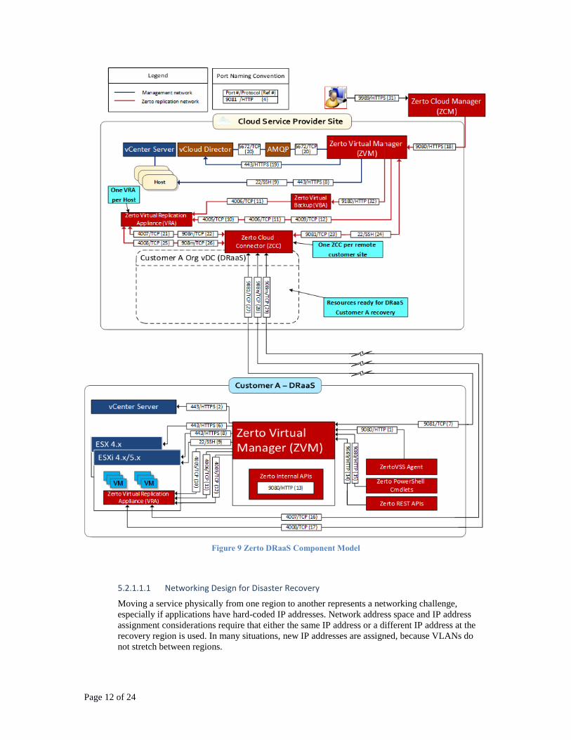
Figure 9 Zerto DRaaS Component Model
5.2.1.1.1 Networking Design for Disaster Recovery
Moving a service physically from one region to another represents a networking challenge,
especially if applications have hard-coded IP addresses. Network address space and IP address
assignment considerations require that either the same IP address or a different IP address at the
recovery region is used. In many situations, new IP addresses are assigned, because VLANs do
not stretch between regions.

Page 13 of 24
While protecting the management applications, it is possible to simplify the problem of IP address
assignment. This design leverages a load balancer to separate a public network segment and a
private network segment. The private network can remain unchanged and only the external load
balancer interface has to be reassigned.
On the public network segment, the management application is accessible via one or more virtual
IP (VIP) addresses
On the isolated private network segment, the application's virtual machines are isolated
After a failover, the recovered application is available under a different IPv4 address (VIP). The
use of the new IP address requires changes to the DNS records. DNS records are either changed
manually or by using a script in the Zerto Virtual Manager recovery plan.
Figure 10 Logical Network Design for Recover to Cloud & Migration Platform
Figure 11 Logical Network Design for Intra Cloud DR

Page 14 of 24
Figure 12 Logical Network Design for DRaaS
The IPv4 subnets are routed within the vSphere management network of each region. Nodes on
these network segments are reachable from within the SDDC. IPv4 subnets, such as the subnet for
the vRealize Automation primary components, overlap across a region. Make sure that only the
active IPv4 subnet is propagated in the region and beyond. The public facing Ext-Mgmt network
of both regions (grey networks) are reachable by users and provide connection to external
resources, such as Active Directory or DNS.
Load balancing functionality is provided by NSX Edge services gateways. In each region, the
same configuration for the management applications and their Zerto Virtual Manager shadow will
be used. Active Directory and DNS services must be running in both the protected and recovery
regions.
5.2.1.1.2 Zerto Replication
The Zerto Virtual Replication Appliances (VRA) copies I/O as it is created before it leaves the
hypervisor. This continuous block-level replication delivers RPOs of seconds, minimizing data
loss in the event of an outage.
Writes are captured by the Zerto Virtual Replication software in the hypervisor level, before they
are written to the physical disk at the protected site. These writes are sent to the recovery site
asynchronously, thus avoiding long distance replication latency for the production applications.
Also, because these writes are captured and sent to the recovery site, it is only the delta changes
and not the whole file or disk that is sent to the recovery site, reducing the amount of network
traffic, which reduces WAN requirements and significantly improves the ability to meet both RPO
and RTO targets.
5.2.1.1.3 Virtual Protection Groups
Virtual machines are protected in virtual protection groups (VPG). A VPG is a group of virtual
machines that you group together for recovery purposes.

Page 15 of 24
Once a virtual machine is protected, all changes made on the machine are replicated in the remote
site. The replicated virtual machines in the remote site can be recovered to any point in time
defined for the VPG or if a period further in the past is required, an offsite backup can be restored.
When a VPG is created, a replica of each virtual machine disk in the VPG is created under a VRA
on the recovery site. These replica virtual disks must be populated with the data in the protected
virtual machines, which is done by synchronizing the protected virtual machines with the recovery
site replicas. This synchronization between the protected site and remote site takes time,
depending on the size of the virtual machines and the network capacity between sites.
After the initial synchronization completes, only the writes to disk from the virtual machines in the
protected site are sent to the remote site. These writes are stored by the VRA in the remote site in
journals for a specified period, after which they are promoted to the replica virtual disks managed
by the VRA.
5.2.1.1.1 Messages and Commands for Zerto Virtual Manager
Zerto also provides a set of RESTful APIs and PowerShell cmdlets to enable incorporating some
of the disaster recovery functionality within scripts or programs.
Before and after executing a failover, move, or test failover, you can run executable scripts, such
as Windows .bat files or PowerShell scripts. A pre-recovery script is always run at the beginning
of the recovery operation. A post-recovery script is run after all the virtual machines are powered
on at the recovery site.
The scripts must be saved to the machine where the remote Zerto Virtual Manager (ZVM) is
installed.
Both pre-recovery and post-recovery scripts are run by the ZVM service on the ZVM machine.
The account running the ZVM service is the account that will run the scripts when they are
executed
5.2.1.1.2 Recovery Flow for Zerto Virtual Manager
Zerto Virtual Replication enables protecting virtual machines, for both disaster recovery or for
extended, longer term recovery from an offsite backup, by protecting the relevant virtual machines
in virtual protection groups. A virtual protection group (VPG) is a group comprised of virtual
machines that are grouped together for recovery purposes.
Disaster recovery using Zerto Virtual Replication enables recovering from a disaster to any point
between the moment just before the disaster and a specified amount of time in the past up to 30
days. The recovery is done in real time at the recovery site with a minimal RTO.
A recovery operation is one of the following:
A failover.
A planned move of the protected virtual machines from the protected site to the recovery
site.
A clone of the protected virtual machine to the recovery site.
Virtual machines are protected in VPGs. Once a VPG is created, Zerto Virtual Replication creates
a copy under the management of a Virtual Replication Appliance, VRA, on the recovery site, of
the protected virtual machine files, such as the configuration and data files. A VRA is installed on
every host where the machines are to be recovered.
When a recovery operation is performed, the VRA creates the virtual machines defined in the
VPG and attaches the virtual disks to these machines. It then promotes the data from the journal to
the virtual machine disks.
After initializing the VPG, all writes to the protected virtual machines are sent by the VRA on the
relevant host for each virtual machine on the protected site to the VRA on the recovery site
specified as the recovery host for the virtual machine. The information is saved in the journal for

Page 16 of 24
the virtual machine with a timestamp, ensuring write-fidelity. Every few seconds the Zerto Virtual
Manager causes a checkpoint to be written to every journal on the recovery site for every virtual
machine in the VPG, ensuring crash-consistency.
The data remains in the journal until the time specified for the journal when it is moved to the
relevant mirror disks, also managed by the VRA for the virtual machine. In this way, you can
recover the virtual machines using the mirror disks and then promoting the data from the journal
to include the final few hours of data for each virtual machine.
5.2.1.1.3 Recovery Plan Test Network
When a recovery plan is created, the test network options must be defined at VPG level. Selecting
an existing port group provides a granular configuration to meet the client’s testing requirements.
For virtual machines across ESXi hosts to communicate, distributed switches with uplinks to the
production network are used and a port group is created on the switch that is tagged with a non-
routable VLAN. In this way, the network is isolated and cannot communicate with other
production networks.
Because the isolated application networks are fronted by a load balancer, the recovery plan test
network is equal to the recovery plan production network and provides realistic verification of a
recovered management application.
5.2.1.1.4 Sizing
For each region, 1 Zerto Virtual Manager and one Zerto Virtual Replication appliance per each
ESXi host are deployed. The ZVM application is installed on a Windows 2012R2 virtual machine
and utilizes the built in SQL based DB. The Zerto Virtual Replication application is deployed as a
virtual appliance.
5.3 Common Services
Common services provide the services used by other services in the cloud management platform. This
includes identity and access services, domain name services, NTP services, SMTP services and Certificate
Authority Services.
5.3.1 Identity and Access Services
In this design, Microsoft Active Directory (AD) is employed. One MS Windows Active Directory VM will
be deployed as part of the VCF automated bring up process. VCF ESXi hosts, vCenter – SSO domain and
NSX will be configured to utilize MS AD authentication.

Page 17 of 24
5.3.1.1 MS AD
A single Microsoft Active Directory (AD) VM is deployed within the VCF instance. MS AD
serves to authenticate users to the management of the VCF instance only and is not meant to house
end users of the workloads deployed within VCF. The forest root of the MS AD will equal the
DNS domain name specified by the customer. This domain name is specified only for the first
VCF instance if multiple instances are linked. In the case of linked instances of VCF, each VCF
instance will contain an AD server that in the forest root replica ring. DNS zone files will also be
replicated.
5.3.1.2 vSphere SSO domain
The vSphere Single Sign On (SSO) domain is used as the initial authentication mechanism for a
single or multiple VCF instances which are linked. It also serves to connect a VCF instance or
instances to Microsoft Active Directory. With regards to VCF, the following SSO configuration is
employed:
The customer inputs the SSO domain name to be used, but the recommendation should
be to utilize the default SSO domain name of “vsphere.local” The SSO domain cannot
equal the DNS / AD domain name specified.
For instances of VCF that will be tied to an existing instance, the SSO domain of the first
VCF instance will automatically be used.
The SSO site name will equal the VCF instance name.
5.3.2 Domain Name Services
Domain Names Services (DNS) within this design are for the cloud management and infrastructure
components only.
VCF utilizes VMware Cloud Foundation automation. Cloud Foundation utilizes its own DNS server, which
resides within the SDDCmgr VM component. SDDCmgr managed VCF components (vCenter, PSC, NSX,
ESXi hosts) are configured to point to the SDDCmgr VM IP address as their default DNS by design.
Because the SDDCmgr generates and maintains host names for the things it manages, it is not
recommended to tamper with its DNS zone file directly for adding and removing hosts.
The end user will be allowed add host names (“A” records) and IP addresses into the SDDCmgr VM dns
server zone via the IBM Cloud for VMware solutions portal.
This design integrates DNS services on the deployed MS AD VMs with the SDDCmgr VM in the
following configuration:
The domain structure is specified by the customer. The domain name can be any number of levels
(up to the maximum that all VCF components will handle), with the lowest level being the
subdomain that the SDDCmgr is authoritative for.
o The DNS domain name entered will be used as the VCF deployed AD root forest domain
name. (if the DNS domain name = cloud.ibm.com then AD domain forest root =
cloud.ibm.com) Note that this DNS domain and AD domain is the same across all
federated instances of VCF
o The VCF instance name entered as the VCF instance subdomain. (if the VCF instance
name = SJC03 then the subdomain that the sddcmgr will own and deploy the cluster into
= SJC03.cloud.ibm.com) This domain name must be unique across all linked VCF
instances.
The SDDCmgr DNS configuration is altered to point to the deployed MS AD servers are
forwarders for all zones other then the zone it is responsible for.
The MS AD DNS servers are configured to be authoritative for the DNS domain space above the
SDDCmgr / VCF instance subdomain.
The MS AD DNS servers are configured to point to the SDDCmgr IP address for the subdomain
delegation of the zone the SDDCmgr is authoritative for.

Page 18 of 24
ANY Secondary cloud regions that are to be integrated to the first or target deployed cloud region
must utilize the same DNS name structure above the SDDCmgr subdomain.
5.3.3 NTP Services
This design’s NTP servers are a substratum of the IBM Cloud infrastructure NTP server deployed on the
MS Active Directory virtual machines. All VCF deployed components will be configured to utilize these
NTP servers. Having all components within the design utilizing the same NTP servers is critical for
certificates and MS AD authentication to function correctly.
5.3.4 Certificate Authority Services
By default, VMware vSphere 6.0 uses TLS or SSL certificates that are signed by VMware Certificate
Authority (VMCA) residing on the VMware Platform Services Controller appliance. These certificates are
not trusted by end-user devices or browsers. It is a security best practice to replace user-facing certificates
with certificates that are signed by a third-party or enterprise CA. Certificates for machine-to-machine
communication can remain as VMCA-signed certificates, however it is highly recommended that
customers follow best practices for their organization, which typically involve using an identified enterprise
certificate authority (CA).
The Windows AD servers within this design can be used to create local instance signed certificates. At this
time it is up to the customer to configure Certificate Authority services if needed.

Page 19 of 24
6 Logical Operational Model
The logical operational model provides guidance as to the design elements required to meet the functional
requirements.
6.1 Logical Operational Model Structure
The design consists of two distinct elements. A central cloud, through which the user and service provider
manage the entire cloud, and optionally, one or more associated cloud regions. Only the central cloud
contains the self-service portal. Additional regions (cloud regions) are added to provide remote sites, or
additional capacity beyond that of a single central cloud within the same site. Each cloud region is
configured into the central cloud for management. On premises vSphere environments are connected to
SoftLayer via either a VPN connection over the internet or dedicated links to form additional cloud regions.
The design of on premises vSphere environments is outside the scope of this document.
Figure 13 Logical Structure View

Page 20 of 24
Within a central cloud, the components interact with each other as follows:
Figure 14 Component Interaction Diagram
Both the central cloud and any additional cloud regions are built on SoftLayer.

Page 21 of 24
7 Physical Operational Model The physical operational model elaborates by applying the non-functional requirements to the logical
operational model.
SoftLayer Private Network
BCR
SoftLayer Public Network
SoftLayer File Storage
SoftLayerNTP Service
SoftLayerDNS Service
SoftLayer Services Network
ESG-Mgmt-NS (X Large)
UDLR
networkExchange Transit Nework
Protected Workload VMs
FCR
MBR
Central Cloud
BCR
SoftLayer File Storage
SoftLayerNTP Service
SoftLayerDNS Service
ESG-Mgmt-NS (X Large)
UDLR
Workload VXLAN
FCR
MBR
Cloud Region
SoftLayer Backbone
DAR DAR
Protected Workload VMs
(shadow)
SoftLayer Private Network
SoftLayer Services Network
SoftLayer Public Network
Vritual Replication Appliance
Workload VXLAN
Zerto Virtual Manager
Virtual Replication ApplianceZerto Virtual
Manager
Figure 15 Physical Operational Model - Intra Cloud DR
Management Network
Public Network
File StorageNTP Service DNS Service
Common Services Network
ESG-Mgmt-NS (X Large)
DLR
networkExchange Transit Nework
Protected Workload VMs
Router
Customer On Premise
BCR
SoftLayer File Storage
SoftLayerNTP Service
SoftLayerDNS Service
ESG-Mgmt-NS (X Large)
DLR
Workload VXLAN
Vyatta
SoftLayer
Protected Workload VMs
(shadow)
SoftLayer Private Network
SoftLayer Services Network
SoftLayer Public Network
Vritual Replication Appliance
Workload VXLAN
Zerto Virtual Manager
Virtual Replication ApplianceZerto Virtual
Manager
FCR
VPN
Figure 16 Physical Operational Model – DRaaS, Recover to Cloud & Migration Platform

Page 22 of 24
8 Architectural Decisions
# AD Decision
1 Site Failure One of the sites have to survive to the emergency condition and take-over
the failing site workload. The sites must be geographic distant and not
subject to the same risk conditions, which might cause the concurrent
unavailability of sites.
3 Cloud Components
scaling
Cloud components in the surviving site require to be scaled-out to start new
compute instances where the failing site workload can be took-over.
4 Cloud Components
re-provisioning
Cloud components not available in the surviving site require to be re-
provisioned and configured so that they can took-over extra workload in
emergency.
5 WAN circuits
scaling
Network bandwidth in the surviving site should be able to scale-up to
accommodate the additional network traffic that would be routed in
emergency.
6 Zerto call home Zerto Virtual Replication requires the ability to connect to zerto.com for
usage reporting and to enable product support and updates. An NSX Edge
Services Gateway S-NAT rule should be configured for the ZVM virtual
machine to connect to zerto.com
7 VRA addressing Zerto’s VRAs do not support multi-homing or NAT traversal. Zerto VRAs
may be deployed using SoftLayer private IP addresses or using customer-
provided IP addresses. Using SoftLayer addressing simplifies the cloud to
cloud replication case, but the on premise to cloud replication case
becomes possible only if the SoftLayer private addresses are tunneled to
the on premise deployment. If this tunneling is not feasible then it is
necessary to re-deploy the VRAs in SoftLayer using VXLAN and customer
provided IP addresses.

Page 23 of 24
Appendix A – Software Bill of Materials The following software products and versions are used in this design.
Table 3 Software Bill of Materials
Manufacturer Product Name Product Version
Zerto Virtual Replication 5.0U1
Microsoft Windows Server Standard 2012R2

Page 24 of 24
Appendix B – Management Virtual Machine Summary The following virtual machines are configured in the management cluster for the cloud management
platform by default, as well on the DR site(s).
Table 4 List of Virtual Machines and Sizes per site
Function vCPU
vRAM
(GB)
vDisk
(GB)
Zerto Virtual Manager (ZVM) 2 4 100
Virtual Replication Appliances (VRAs)
(One per each ESXi host) 1 3 11