ibm cloud for vmware solutions vmware on ibm cloud ...€¦ · vmware on ibm cloud solution...
TRANSCRIPT

Copyright IBM Corporation 2017 Page 1 of 28
IBM Cloud for VMware Solutions VMware on IBM Cloud
Solution Architecture
Date: 2017–11–15
Version: 3.0

Copyright IBM Corporation 2017 Page 2 of 28
Table of Contents
1 Introduction................................................................................................................................ 4
1.1 About VMware on IBM Cloud .............................................................................................. 4
1.2 Key Benefits ........................................................................................................................ 4
2 Design ....................................................................................................................................... 6
2.1 Overview.............................................................................................................................. 6
2.2 Physical Infrastructure ......................................................................................................... 6
Physical Host Design .................................................................................................. 7
Physical Network Design ............................................................................................ 7
Physical Storage Design .......................................................................................... 10
2.3 Virtual infrastructure .......................................................................................................... 12
VMware vSphere Design .......................................................................................... 12
VMware vSAN Design .............................................................................................. 13
VMware NSX Design ................................................................................................ 14
2.4 Common Services ............................................................................................................. 18
Identity and Access Services.................................................................................... 19
Domain Name Services ............................................................................................ 19
NTP Services ............................................................................................................ 20
Certificate Authority Services ................................................................................... 21
2.5 Infrastructure Management ............................................................................................... 21
Platform Services Controller Design ........................................................................ 22
vCenter Server Design ............................................................................................. 22
Cloud Builder and Cloud Driver ................................................................................ 23
SDDC Manager ........................................................................................................ 24
Automation flow ........................................................................................................ 24
2.6 Scale .................................................................................................................................. 24
Multi–site deployments ............................................................................................. 24
Scale Out with New Cluster ...................................................................................... 25
Scale Out Existing Cluster ........................................................................................ 25
2.7 Backup ............................................................................................................................... 25
NSX Backup ............................................................................................................. 25
Appendix A – License Requirements ............................................................................................. 26
Copyright IBM Corporation 2017 Page 3 of 28
Summary of Changes This section records the history of significant changes to this document.
Version Date Author Description of Change
2.0 2016–12–13 Simon Kofkin–Hansen
Daniel de Araujo
Frank Chodacki
Bob Kellenberger
Daniel Arrieta Alvarez
New design document replacing original 1.0
2.1 2017–03–10 Same Corrected VLAN allocations in Table 5
Removed order process section
3.0 2017–11–15 Simon Kofkin–Hansen
Daniel de Araujo
Frank Chodacki
Bob Kellenberger
Jim Robbins
Robert Warren
Scott Moonen
Converge vCenter Server and VMware Cloud
Foundation architectures
Addition of vSAN support for vCenter Server
Update for vSphere 6.5

Copyright IBM Corporation 2017 Page 4 of 28
1 Introduction
1.1 About VMware on IBM Cloud
The IBM Cloud for VMware Solution offerings enable existing VMware virtualized datacenter clients to
extend into the IBM Cloud or to house cloud native applications. This permits use cases like capacity
expansion into the cloud (and contraction when not needed), migration to the cloud, disaster recovery to the
cloud, backup into the cloud and the ability to stand up a dedicated cloud environment for development,
testing, training, lab or production.
This document details the design of the IBM Cloud for VMware Solutions offerings, including both
VMware Cloud Foundation and VMware vCenter Server, which target workloads requiring high levels of
availability and scalability. This design serves as a baseline architecture providing the foundation for other
internal or vendor specific components to be added in as required by specific use cases.
Figure 1 Overview of VMware on IBM Cloud
1.2 Key Benefits
VMware Cloud Foundation® (VCF) and vCenter Server (VCS) on IBM Cloud provide the fundamental
building blocks that include VMware vSphere, vCenter Server, NSX, and shared storage options including
vSAN, needed to flexibly architect a VMware software–defined data center (SDDC) solution that best fits
the client’s workloads. By using advanced automation and single–tenant bare metal infrastructure, the
entire VMware environment is rapidly deployed to the IBM Cloud and made available to the client in a
matter of hours. At this point, the client can access and manage the IBM–hosted environment via the native
VMware clients, Command Line Interface (CLI), existing scripts, or other familiar vSphere API–
compatible tools.
Post deployment, the client can add additional ESXi host nodes and manage the preconfigured backup and
patching of some management components. IBM Cloud Professional Services and Managed Services are
also available to help accelerate the client’s journey to the cloud with offerings like migration,
implementation and onboarding services.
In summary, the VMware on IBM Cloud offerings:
• Accelerate delivery of IT projects to developers and lines of business by reducing the time it
takes for procurement, architecture, implementation, and deployment of resources from weeks or
even months, to hours
• Enhance security with dedicated bare metal servers in a hosted private cloud, including the
encryption of data at rest*

Copyright IBM Corporation 2017 Page 5 of 28
• Enable consistent management and governance of the deployed hybrid cloud by providing full
administrative access to virtualization management, thus preserving your existing VMware
tooling, scripts, and investments in training
• Leverage VMware expertise at global scale with IBM Professional and Managed Services
spanning 30+ IBM Cloud data centers worldwide
* When using vSAN storage, encryption of data at rest is optional using either vSAN or vSphere
encryption. When using shared file–level storage, service–provider–managed encryption at rest is
available by default in select data centers, or is optional using vSphere encryption.

Copyright IBM Corporation 2017 Page 6 of 28
2 Design
2.1 Overview
The IBM Cloud for VMware solutions provide automation to deploy VMware technology components in
IBM Cloud datacenters across the globe. The offerings in this solutions portfolio include the following
VMware vSphere products within an automated deployed and configured cluster:
• VMware Cloud Foundation (VCF): vSphere ESXi, Platform Services Controller (PSC), vCenter
Server Appliance, SDDC Manager, NSX, and vSAN.
• VMware vCenter Server (VCS): vSphere ESXi, Platform Services Controller (PSC), vCenter
Server Appliance, NSX, and optionally vSAN.
The architecture consists of a single cloud region and supports the ability to extend into additional cloud
regions that are located in another geography and/or into another IBM Cloud pod within the same
datacenter. Note that a region is defined as a unique VCF or VCS instance. This design also allows for
automated expansion and contraction of virtual capacity within a VCF or VCS instance.
Figure 2 Solution Components of VMware on IBM Cloud
2.2 Physical Infrastructure
The physical infrastructure consists of three main components including physical compute, physical storage
and physical network. The physical compute provides the physical processing and memory that is used by
the virtualization infrastructure. The physical storage provides the raw storage capacity consumed by the
virtualization infrastructure. The physical network provides the network connectivity into the environment
that is then consumed by the network virtualization. For this design, the compute components are provided
by IBM Cloud bare metal servers and are listed on the VMware Hardware Compatibility Guide (HCG).
Storage components are provided either by IBM Cloud bare metal servers or by shared Network Attached
Storage (NAS) array using NFSv3. The network is provided by the IBM Cloud services network, and
includes additional services such as DNS and NTP. Please see the VMware on IBM Cloud Bill of Materials
document for more information on the specific hardware used in this solution; and the shared storage
reference architecture document for more information on the shared NAS used in this solution.

Copyright IBM Corporation 2017 Page 7 of 28
Physical Host Design
Physical compute refers to the bare metal hosts in the environment. The bare metal hosts recommended in
this solution are certified on the VMware Hardware Compatibility Guide and meet or exceed the minimum
requirements necessary to install, configure, and manage vSphere ESXi. A variety of configurations are
available to satisfy different requirements. A detailed listing of the exact specifications used for the
VMware on IBM Cloud solution offerings is listed in another document known as the hardware bill of
materials (BOM). Note these bare metal hosts reside within the IBM Cloud. Each VCF instance begins
with a 4–host deployment, and each VCS instance begins with a 3– or 4– host deployment (depending on
the choice of storage solution).
The physical host hardware BOM employs 2 locally attached disks allocated to the vSphere ESXi
hypervisor. Additional disks may be allocated for vSAN or NetApp ONTAP Select shared storage
solutions. The vSAN architecture is detailed later in this document, and the NetApp ONTAP Select
solution is discussed in a separate NetApp ONTAP Select architecture. The physical hosts all have
redundant 10 Gbps network connections for both public and private network access.
CPU Memory Network Number of Drives
Dual Intel Xeon, varying
core and speed
configuration
Varying
configuration
64GB and larger
4 × 10 Gbps 2 or more
Table 1 Physical Host Summary
Physical Network Design
Physical networking is handled by IBM Cloud. This section will describe the physical network provided by
the IBM Cloud and physical host connections (VLANs, MTU) associated with the physical hosts described
in the previous section.
IBM Cloud Network Overview
The physical network of IBM Cloud is separated into three distinct networks: Public, Private, and
Management.

Copyright IBM Corporation 2017 Page 8 of 28
Figure 3 IBM Cloud High–Level Network
Public Network
IBM Cloud data centers and network points of presence (PoP) have multiple 1 Gbps or 10 Gbps
connections to top–tier transit and peering network carriers. Network traffic from anywhere in the
world will connect to the closest network PoP, and it will travel directly across the network to its
data center, minimizing the number of network hops and handoffs between providers. Inside the
data center, 1Gbps or 10 Gbps of network bandwidth is provided to individual servers via a pair of
separate, peered aggregated frontend customer switches (FCS). These aggregated switches are
attached to a pair of separate routers (i.e., frontend customer routers, FCR) for L3 networking.
This multi–tier design allows the network to scale across racks, rows, and pods within an IBM
Cloud datacenter.
Private Network
All IBM Cloud data centers and PoPs are connected by the private network backbone. This private
network is separate from the public network, and it enables connectivity to services in IBM Cloud
data centers around the world. Moving data between data centers is done via multiple 10 Gbps or
40 Gbps connections to the private network. Similar to the public network, the private network is
multi–tiered in that servers and other infrastructure are connected to an aggregated backend
customer switches (BCS). These aggregated switches are attached to a pair of separate routers
(i.e., backend customer routers, BCR) for L3 networking. The private network also supports the
ability to utilize jumbo frames (MTU 9000) for physical host connections.
Management Network
In addition to the public and private networks, each IBM Cloud server is connected to an out–of–
band management network. This management network, accessible via VPN, allows Intelligent
Platform Management Interface (IPMI) access to the server independently of its CPU, firmware
and operating system for maintenance and administration purposes.
Primary and portable IP Blocks
IBM Cloud allocates two types of IP addresses to be used within IBM Cloud infrastructure:
• Primary IP addresses are assigned to devices, bare metal and virtual servers provisioned by
IBM Cloud. End users should not assign any IP addresses in these blocks.
• Portable IP addresses are provided for the end user to assign and manage as needed.
Primary or Portable IP addresses can be made routable to any VLAN within the customer account
if either VLAN Spanning is enabled within the account or the account is configured as a virtual
routing and forwarding (VRF) account.

Copyright IBM Corporation 2017 Page 9 of 28
VLAN Spanning
VLAN Spanning is an IBM Cloud global account setting that allows each Primary and Portable
subnet IP block within all VLANs within the account to be routable to each other. With this
setting disabled, IP blocks can still route to IBM Cloud services, but not each other. This
architecture requires VLAN Spanning to be enabled within the account where VCF and VCS are
deployed, in order that connections can be transparently made across the various subnets where
the solution components reside.
Virtual Routing and Forwarding (VRF)
IBM Cloud accounts may also be configured as a VRF account. This provides similar
functionality to VLAN spanning, enabling automatic routing between subnet IP blocks. All
accounts with Direct Link connections must be converted to, or created as, a VRF account.
Unfortunately, at the time of this writing the IBM Cloud UI cannot detect that VRF is enabled, so
it will issue a warning that you must ensure either VLAN spanning or VRF is configured in your
IBM Cloud account.
Physical Host Connections
Each physical host within the design has two redundant pairs of 10Gbps Ethernet connections into
each IBM Cloud Top of Rack (ToR) switch (public and private). The adapters are setup as
individual connections (unbonded) for a total of 4 × 10Gbps connections. This allows each
networking interface card (NIC) connection to work independent of one another.
Figure 4 Physical Host Connections
VLANs
The VMware on IBM Cloud offerings are designed with 3 VLANs (one public and two private)
assigned upon deployment. The public VLAN is assigned to eth1 and eth3, while the private
connections are assigned to eth0 and eth2. It is important to note that the public and the first
private VLAN created and assigned to this design are untagged by default within the IBM Cloud.
Subsequently, the additional private VLAN is trunked on the physical switch ports and tagged
within the VMware port groups that are consuming these subnets.
As stated previously, the private network consists of two VLANs within this design. Three subnets
are allocated to the first of these VLANs (here designated Private VLAN A): the first is a primary

Copyright IBM Corporation 2017 Page 10 of 28
private IP subnet range IBM Cloud assigns to the physical hosts. The second subnet is used for
management virtual machines (e.g., vCenter Server Appliance, Platform Services Controller). The
third is utilized for the VXLAN Tunnel Endpoints (VTEPs) assigned to each host via the NSX
Manager.
In addition to Private VLAN A, a second private VLAN (here designated Private VLAN B) exists
to support VMware features such as vSAN and vMotion, and for connectivity to network attached
storage (NAS). As such, the VLAN is divided into two or three portable subnets. The first subnet
is assigned to a kernel port group for vMotion traffic. The remaining subnet or subnets are used
for storage traffic: when using vSAN, one will be assigned to kernel port groups used for vSAN
traffic; when using NAS, one will be assigned to a port group dedicated to NFS traffic. Note all
subnets configured as part of a VCF or VCS automated deployment utilize IBM Cloud managed
ranges. This is to ensure any IP address can be routed to any data center within the IBM Cloud
account being used if it is required currently or in future.
This is all summarized in Table 2:
VLAN Type Description
Public Primary Assigned to physical hosts for public network access. Not
utilized upon initial deployment.
Private A Primary Single subnet assigned to physical hosts assigned by IBM Cloud.
Used by the management interface for vSphere management
traffic.
Private A Portable Single subnet assigned to virtual machines functioning as
management components.
Private A Portable Single subnet assigned to NSX VTEP
Private B Portable Single subnet assigned for vSAN, if in use
Private B Portable Single subnet assigned for NAS, if in use
Private B Portable Single subnet assigned for vMotion
Table 2 VLAN and Subnet Summary
This design is deployed with all VLAN–backed hosts and virtual machines configured to point to
the IBM Cloud BCR (backend “private network” customer router) as the default route. While VCF
and VCS instances enable the use of Software–Defined Networking (SDN), note any network
overlays created within a VMware instance which include routing to internal subnets are not
known by the IBM Cloud managed routers. Therefore, you may need to create static routes within
the VMware instance on some or all management components.
The private network connections are configured to use jumbo frame MTU size of 9000 which
improves performance for large data transfers such as storage and vMotion. This is the maximum
MTU allowed within VMware and by IBM Cloud. The public network connections use a standard
Ethernet MTU of 1500. This must be maintained as any changes may cause packet fragmentation
over the internet.
Physical Storage Design
This section discusses the configuration of the physical disks installed in each physical host, and
the configuration of shared file–level storage. This includes the OS (vSphere ESXi) disks as well
as those used for storage of the virtual machines. Storage used for virtual machines may be
comprised either of local disks virtualized by VMware vSAN, or of shared file–level storage.

Copyright IBM Corporation 2017 Page 11 of 28
Operating System Disks
The vSphere ESXi hypervisor is designed to be installed in a persistent location. As a result, the
physical hosts are comprised of two 1TB SATA disks in a RAID–1 configuration to support
redundancy for the vSphere ESXi hypervisor.
vSAN Disks
This design allows for the option of using either VMware vSAN or shared file–level storage as the
primary datastore for virtual machines. When using VMware vSAN, it is configured using an all–
flash configuration. This design allows for several configuration options, including 2U and 4U
chassis, a variety of numbers of disks, and a variety of disk sizes. All configurations use two
vSAN disk groups, with one solid state disk (SSD) for cache and one or more SSDs for capacity.
All drives allocated for vSAN consumption are configured in single–disk RAID–0. For details on
the supported configurations, refer to the VMware on IBM Cloud BOM document.
Shared File–Level Storage Across Hosts
This design allows for the option of using either VMware vSAN or shared file–level storage as the
primary datastore for virtual machines. When using shared file–level storage, one 2TB NFS share
is attached to the hosts that comprise the initial VMware cluster. This share, known as the
management share, is used for management components such as the VMware vCenter Server,
Platform Services Controller, and VMware NSX. The storage is attached via the NFSv3 protocol
and has the ability to support up to 4000 IOPS.
Figure 5 NFS shares attached to VMware deployment
Additional file shares for customer workloads can also be allocated and mounted across all hosts
at the time of purchase or later within the console. The user can select from the available IBM
Cloud Endurance file storage capacity options and performance tiers in the corresponding IBM
Cloud data center. All shares are attached using the NFSv3 protocol. Additionally, it is possible to
attach NFSv3 file shares from the NetApp ONTAP Select offering.
Note that the availability of the 10 IOPS/GB depends on the IBM Cloud data center. Data centers
that offer the 10 IOPS/GB performance tier also include provider–managed encryption of data at

Copyright IBM Corporation 2017 Page 12 of 28
rest (AES–256 encryption), and are backed by all–flash storage. At the time of this writing, the 10
IOPS/GB performance tier is limited to a maximum capacity of 4 TB. Please see the shared
storage reference architecture document for more information on the shared NAS used in this
solution.
2.3 Virtual infrastructure
The virtual infrastructure design includes the VMware software components that make up the virtual
infrastructure layer of the VMware on IBM Cloud solution. These components include the software
products that provide compute, storage, and network virtualization. The VMware products in this layer
include vSphere ESXi, VMware NSX, and optionally VMware vSAN.
VMware vSphere Design
The vSphere ESXi configuration consists of five main elements: boot configuration, time synchronization,
host access, user access, and configuration of DNS. Table 3 outlines the respective specifications for these.
After configuration and installation of ESXi, the host is added to a VMware vCenter Server™ and is
managed from there. To gain direct access to the host, the design supports three methods: Direct Console
User Interface (DCUI), ESXi Shell, and Secure Shell (SSH). The administrator can add users from the
Active Directory domain to enable user access to the host. By default, the only users who can log in
directly are the root and ibmvmadmin users of the host’s physical machine. All hosts in vCenter Server
solution design are configured to sync with a central NTP server.
Attribute Configuration parameter
ESXi boot location Uses local disks configured in RAID–1
Time sync Uses IBM Cloud NTP Server
Host access Supports DCUI, ESXi Shell, or SSH
User access Local Authentication and MS Active Directory
Domain Name Resolution Uses DNS referenced in section 2.4.2
Table 3 vSphere ESXi Configuration
When configured with vSAN storage, a VMware on IBM Cloud instance is provisioned with a vSphere
cluster of a minimum of 4 ESXi hosts up to a maximum of 32. When a vCS instance is configured only
with shared file–level storage, it is provisioned with a minimum of 3 ESXi hosts. The vSphere cluster
houses the virtual machines that manage the central cloud as well as compute resources for user workloads.

Copyright IBM Corporation 2017 Page 13 of 28
When the environment is scaled out to support more user workloads, the environment can scale out the
converged cluster by deploying additional compute hosts, by deploying additional clusters managed by the
same vCenter, or by deploying a new VCF or VCS instance with its own vCenter Server Appliance. For
more details refer to the IBM Cloud running VMware Clusters solution architecture document.
VMware vSAN Design
For this design, VMware Virtual Storage Area Network (vSAN) storage is employed within VCF and
optionally within VCS to provide shared storage for the vSphere hosts. vSAN aggregates the local storage
across multiple ESXi hosts within a vSphere cluster to be represented as a single virtual machine datastore.
Within this design, the compute nodes contain local disk drives for the ESXi OS and the vSAN datastore.
Two 1TB SATA drives are excluded in each node regardless of which cluster it belongs to for the purpose
of housing the ESXi installation.
Figure 6 vSAN Concept
Virtual SAN Design
vSAN employs the following components:
• Two–disk–group vSAN design, with each disk group consisting of two or more disks per disk
group. One SSD of the smallest size in the group serves as the cache tier and the remaining
SSDs serve as the capacity tier.
• The onboard raid controller is configured with each drive other than the two OS drives,
configured in a RAID–0 array per drive.
• A single vSAN datastore is created using all of the storage.
Virtual network setup
For this design, the vSAN traffic will traverse between ESXi hosts on a dedicated private VLAN.
The two network adapters attached to the private network switch are configured within vSphere as
a vSphere distributed switch (VDS) with both network adapters as uplinks. A dedicated vSAN
kernel port group configured for the vSAN VLAN resides within the VDS. Jumbo frames (MTU
9000) are enabled for the private VDS. Note that vSAN does not load balance traffic across
uplinks. As a result, one adapter is active while the other is in standby to support redundancy. The
network failover policy for vSAN is configured as “Explicit Failover” between physical network
ports. See section 2.2.2.2.
Virtual SAN Policy Design
Once VMware Virtual SAN is enabled and configured, storage policies are configured that define
the virtual machine storage characteristics. Storage characteristics specify different levels of
service for different virtual machines. The default storage policy specified in this design tolerates a
single failure. The default policy is configured with erasure coding, allowing for RAID–5 with a
failures–to–tolerate (FTT) setting of 1. This configuration requires a minimum of four hosts.
Alternatively, a RAID–6 configuration using FTT=2 maybe chosen, requiring a minimum of 6
hosts. Deduplication and compression are also enabled in the default storage policy.

Copyright IBM Corporation 2017 Page 14 of 28
This design will use the default policy unless otherwise specified by the client. If a custom policy
is configured, vSAN will guarantee it if possible. However, if the policy cannot be guaranteed, it
is not possible to provision a virtual machine that uses the policy unless it is enabled to force
provisioning.
Storage policies shall be reapplied upon the addition of new ESXi hosts or patching of the ESXi
hosts.
vSAN Settings
vSAN Settings are set based on experience in deploying VMware solutions within IBM Cloud.
This includes SIOC settings, explicit failover settings port group and disk cache settings.
• SSD drives are configured as no read ahead, write through, direct (NRWTD)
• Network I/O control (NETIOC) settings
o Management = 20 shares
o Virtual Machine = 30 shares
o vMotion = 50 shares
o vSAN = 100 shares
• Configure the vSAN kernel ports to explicit failover
VMware NSX Design
Network virtualization provides a network overlay that exists within the virtual layer. This provides the
architecture with features such as rapid provisioning, deployment, reconfiguration and destruction of on–
demand virtual networks. This design uses the vSphere Distributed Switch (vDS) and VMware NSX for
vSphere to implement virtual networking.
In this design, the NSX Manager is deployed on the initial cluster. Additionally, the NSX Manager is
assigned a VLAN–backed IP address from the private portable address block designated for management
components and configured with the DNS and NTP servers discussed in section 2.4. A summary of the
NSX Manager installation is shown in Table 4.
Attribute Specification
NSX Manager Virtual appliance
Number of vCPUs 4
Memory 16 GB
Disk 60 GB on the management NFS share
Disk type Thin provisioned
Network Private A portable designated for management components
Table 4 NSX Manager Specifications
The following figure shows the placement of the NSX Manager in relation to the other components in this
architecture.

Copyright IBM Corporation 2017 Page 15 of 28
Figure 7 NSX Manager Network Overview
After initial deployment, the IBM Cloud automation deploys three NSX Controllers within the initial
cluster. The controllers are assigned a VLAN–backed IP address from the Private A portable subnet
designated for management components. Additionally, VM–VM anti–affinity rules are created such that
controllers are separated amongst the hosts in the cluster. Note that the initial cluster should be deployed
with a minimum of three nodes to ensure high availability for the controllers.
In addition to the controllers, the IBM Cloud automation prepares the deployed vSphere hosts with NSX
VIBS that enable the use of a virtualized network (i.e., VXLANs) via the use of VXLAN Tunnel Endpoints
(VTEPs). The VTEPs are assigned a VLAN–backed IP addresses from the Private A portable IP address
range specified for VTEPs listed in Table 2 VLAN and Subnet Summary. Note that VXLAN traffic resides
on the untagged VLAN and is assigned to the private virtual distributed switch (vDS). Subsequently, a
segment ID pool is assigned and the hosts in the cluster are added to the transport zone. Note that only
unicast is used in the transport zone since IGMP snooping is not configured within the IBM Cloud.
NSX Edge Services Gateway (ESG) pairs are then deployed. In all cases, one gateway pair is used for
outbound traffic from automation components residing on the private network. In the case of VMware
vCenter Server (VCS), a second gateway, known as the customer–managed edge, is deployed and
configured with an uplink to the public network and an interface assigned to the private network. At this
point, any required NSX component such as, but not limited to, Distributed Logical Router (DLR), logical
switches, and firewalls can be configured by the administrator. For more information on the NSX Edges
that are deployed as part of the solution, please see the additional document named NSX Edge on IBM
Cloud Solution Architecture.
Distributed Switch Design
The design uses a minimum number of distributed switches (vDS). The hosts in the cluster are
connected to public and private networks. They are configured with two distributed virtual
switches. The use of two switches follows the physical network separation of the public and
private networks implemented within IBM Cloud. The following diagram shows the VDS design:
Copyright IBM Corporation 2017 Page 16 of 28
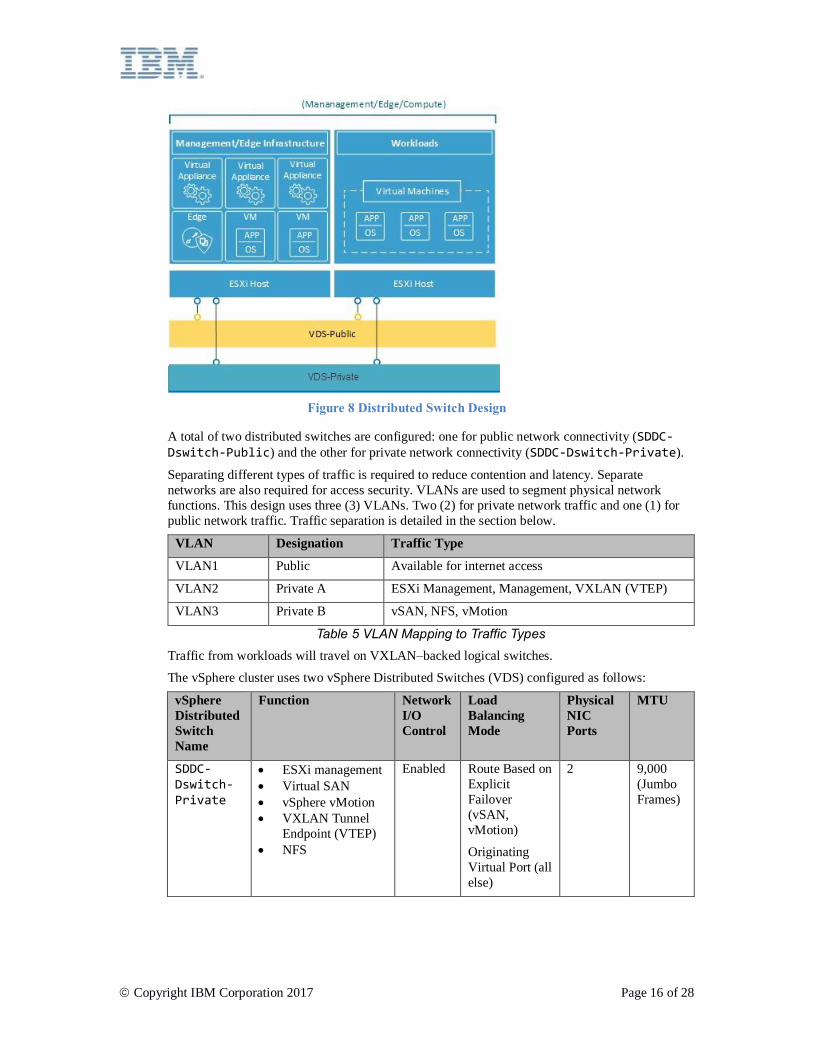
Figure 8 Distributed Switch Design
A total of two distributed switches are configured: one for public network connectivity (SDDC-Dswitch-Public) and the other for private network connectivity (SDDC-Dswitch-Private).
Separating different types of traffic is required to reduce contention and latency. Separate
networks are also required for access security. VLANs are used to segment physical network
functions. This design uses three (3) VLANs. Two (2) for private network traffic and one (1) for
public network traffic. Traffic separation is detailed in the section below.
VLAN Designation Traffic Type
VLAN1 Public Available for internet access
VLAN2 Private A ESXi Management, Management, VXLAN (VTEP)
VLAN3 Private B vSAN, NFS, vMotion
Table 5 VLAN Mapping to Traffic Types
Traffic from workloads will travel on VXLAN–backed logical switches.
The vSphere cluster uses two vSphere Distributed Switches (VDS) configured as follows:
vSphere
Distributed
Switch
Name
Function Network
I/O
Control
Load
Balancing
Mode
Physical
NIC
Ports
MTU
SDDC-Dswitch-Private
• ESXi management
• Virtual SAN
• vSphere vMotion
• VXLAN Tunnel
Endpoint (VTEP)
• NFS
Enabled Route Based on
Explicit
Failover
(vSAN,
vMotion)
Originating
Virtual Port (all
else)
2 9,000
(Jumbo
Frames)

Copyright IBM Corporation 2017 Page 17 of 28
vSphere
Distributed
Switch
Name
Function Network
I/O
Control
Load
Balancing
Mode
Physical
NIC
Ports
MTU
SDDC-Dswitch-Public
• External
management traffic
(North–South)
Enabled Route Based on
Originating
Virtual Port
2 1,500
(default)
Table 6 Converged Cluster Distributed Switches
Parameter Setting
Load balancing Route based on the originating virtual port *
Failover detection Link status only
Notify switches Enabled
Failback No
Failover order Active uplinks: Uplink1, Uplink2 *
* Note that the vSAN port group uses explicit failover with active/standby since it does not
support load balancing of vSAN storage traffic.
Table 7 Converged Cluster Distributed Switch Port Group Configuration Settings
vSphere
Distributed
Switch
Port Group
Name
Teaming Uplinks VLAN ID
SDDC-Dswitch-Private
SDDC-DPortGroup-Mgmt
Originating
virtual port
Active: 0, 1 VLAN1
SDDC-Dswitch-Private
SDDC-DPortGroup-vMotion
Originating
virtual port
Active: 0, 1 VLAN2
SDDC-Dswitch-Private
SDDC-DPortGroup-VSAN
Explicit failover Active: 0
Standby: 1
VLAN2
SDDC-Dswitch-Private
SDDC-DPortGroup-NFS
Originating
virtual port
Active: 0, 1 VLAN2
SDDC-Dswitch-Private
Automatically
generated by NSX
Originating
virtual port
Active: 0, 1 VLAN1
SDDC-Dswitch-Public
SDDC-DPortGroup-External
Originating
virtual port
Active: 0, 1 VLAN3
Table 8 Converged Cluster Virtual Switch Port Groups and VLANs

Copyright IBM Corporation 2017 Page 18 of 28
vSphere
Distributed
Switch
Purpose Connected Port
Group
Enabled Services MTU
SDDC-Dswitch-Private
Management SDDC-DPortGroup-Mgmt
Management
Traffic
1,500
(default)
SDDC-Dswitch-Private
vMotion SDDC-DPortGroup-vMotion
vMotion Traffic 9,000
SDDC-Dswitch-Private
VTEP Automatically
generated by NSX
- 9,000
SDDC-Dswitch-Private
VSAN SDDC-DPortGroup-VSAN
VSAN 9,000
SDDC-Dswitch-Private
NAS SDDC-DPortGroup-NFS
- 9,000
Table 9 Converged Cluster VMkernel Adapters
NSX
This design specifies the configuration of NSX components but does not apply any network
overlay component configuration. It is left up to the customer to design the network overlay based
on their needs. The following is configured:
• Management servers and controllers are installed an integrated into the vCenter web UI
• ESXi agents are installed and VTEP IP addresses are configured per ESXi host
• VTEP configuration, controller configuration, VXLAN configuration (transport zone)
• NSX Edge Services Gateway (ESG) appliances for use by management components
• For vCS only, NSX Edge Services Gateway (ESG) appliances for customer use
What is NOT configured:
• Virtual Distributed routers
• Micro segmentation
• VXLANs
• Linked NSX Management to other VMware instances
2.4 Common Services
Common services provide the services used by other services in the cloud management platform. This
includes identity and access services, domain name services, NTP services, SMTP services and Certificate
Authority Services.

Copyright IBM Corporation 2017 Page 19 of 28
Identity and Access Services
In this design, Microsoft Active Directory (AD) is employed for identity management. A single Windows
Active Directory virtual server instance (VSI) will be deployed as part of the VCF and VCS automation.
vCenter will be configured to utilize MS AD authentication.
Microsoft Active Directory
A single Microsoft Active Directory (AD) VSI is deployed onto the IBM Cloud infrastructure. MS
AD serves to authenticate users to the management of the VMware instance only and is not meant
to house end users of the workloads deployed within VMware. The forest root of the MS AD will
equal the DNS domain name specified by the customer. This domain name is specified only for
the first VCF or VCS instance if multiple instances are linked. In the case of linked instances, each
instance will contain an AD server that is in the forest root replica ring. DNS zone files will also
be replicated.
vSphere SSO domain
The vSphere Single Sign On (SSO) domain is used as the initial authentication mechanism both
for a single or for multiple VMware instances which are linked. It also serves to connect a
VMware instance or instances to Microsoft Active Directory. The following SSO configuration is
employed:
• The SSO domain of vsphere.local is always used
• For VMware instances that will be tied to an existing instance, the PSC will be joined to
the existing instance’s SSO domain
• The SSO site name will equal the VCF or VCS instance name
Domain Name Services
Domain Names Services (DNS) within this design are for the cloud management and infrastructure
components only.
VMware vCenter Server
The VCS deployment utilizes the deployed Microsoft Active Directory (AD) VSIs as DNS servers
for the instance. All deployed components (vCenter, PSC, NSX, ESXi hosts) are configured to
point to the MS AD as their default DNS. User customization of the DNS zone configuration is
permitted provided it does not interfere with the configuration of the deployed components.
This design integrates DNS services on the MS AD VSIs in the following configuration:

Copyright IBM Corporation 2017 Page 20 of 28
• The domain structure is specified by the customer. The domain name can be any number
of levels (up to the maximum that all VCS components will handle), with the lowest level
being the subdomain for the instance.
o The DNS domain name entered will be used as the VCS deployed AD root
forest domain name (e.g., if the DNS domain name = cloud.ibm.com then AD
domain forest root = cloud.ibm.com). Note that this DNS domain and AD
domain is the same across all federated instances of VCS.
o The customer selects an additional name as the VCS instance subdomain. This
subdomain name must be unique across all linked VCS instances.
• The MS AD DNS servers are configured to be authoritative for both the DNS domain and
subdomain space.
• The MS AD DNS servers are configured to point to the IBM Cloud DNS servers for all
other zones.
• Any secondary cloud regions that are to be integrated to the first or target deployed cloud
region must utilize the same DNS name structure above the subdomain.
VMware Cloud Foundation
The VCF deployment utilizes VMware Cloud Foundation automation, which uses its own DNS
server residing within the SDDC Manager VM component. SDDC Manager–managed VCF
components (vCenter, PSC, NSX, ESXi hosts) are configured to point to the SDDC Manager VM
IP address as their default DNS by design. Because the SDDC Manager generates and maintains
host names for the things it manages, it is not recommended to tamper with its DNS zone file
directly for adding and removing hosts.
This design integrates DNS services on the deployed Microsoft AD VSIs with the SDDC Manager
VM in the following configuration:
• The domain structure is specified by the customer. The domain name can be any number
of levels (up to the maximum that all VCF components will handle), with the lowest level
being the subdomain that the SDDC Manager is authoritative for.
o The DNS domain name entered will be used as the VCF deployed AD root
forest domain name (e.g., if the DNS domain name = cloud.ibm.com then AD
domain forest root = cloud.ibm.com). Note that this DNS domain and AD
domain is the same across all federated instances of VCF.
o The customer selects an additional name as the VCF instance subdomain. This
subdomain name must be unique across all linked VCF instances.
• The SDDC Manager DNS configuration is altered to point to the deployed MS AD
servers for all zones other than the zone it is responsible for.
• The MS AD DNS servers are configured to be authoritative for the DNS domain space
above the SDDC Manager / VCF instance subdomain.
• The MS AD DNS servers are configured to point to the SDDC Manager IP address for
the subdomain delegation of the zone the SDDC Manager is authoritative for.
• The MS AD DNS servers are configured to point to the IBM Cloud DNS servers for all
other zones.
• Any secondary cloud regions that are to be integrated to the first or target deployed cloud
region must utilize the same DNS name structure above the SDDC Manager subdomain.
NTP Services
This design utilizes the IBM Cloud infrastructure NTP servers. All deployed components will be
configured to utilize these NTP servers. Having all components within the design utilizing the same NTP
servers is critical for certificates and MS AD authentication to function correctly.

Copyright IBM Corporation 2017 Page 21 of 28
Certificate Authority Services
By default, VMware vSphere uses TLS certificates that are signed by VMware Certificate Authority
(VMCA) residing on the VMware Platform Services Controller appliance. These certificates are not trusted
by end–user devices or browsers. It is a security best practice to replace user–facing certificates with
certificates that are signed by a third–party or enterprise CA. Certificates for machine–to–machine
communication can remain as VMCA–signed certificates, however it is highly recommended that
customers follow best practices for their organization, which typically involve using an identified enterprise
certificate authority (CA).
The Windows AD servers within this design can be used to create local instance signed certificates. At this
time, it is up to the customer to configure Certificate Authority services if needed.
2.5 Infrastructure Management
Infrastructure management refers to the vSphere and, for VCF, the Cloud Foundation components that are
managing the VMware infrastructure. The vCenter Server is the centralized platform for managing vSphere
environments and is one of the fundamental components in this solution. In addition to the vCenter Server,
the Platform Services Controller (PSC) is leveraged in this solution to private a set of infrastructure
services including VMware vCenter Single Sign On, license service, lookup service, and VMware
Certificate Authority.
This design uses a single external Platform Services Controller instance and a single vCenter Server
instance; the Platform Services Controller instances and vCenter Server instance are separate virtual
machines.

Copyright IBM Corporation 2017 Page 22 of 28
Platform Services Controller Design
This design uses a single, external platform services controller installed on a portable subnet on the private
VLAN associated with management virtual machines. Its default gateway is set to the backend customer
router (BCR). The virtual appliance is configured with the specification listed in Table 10. Note these
values are set at the time of deployment and are immutable.
Attribute Specification
Platform Services Controller Virtual appliance
Number of vCPUs 2
Memory 2GB
Disk 30GB on local VMFS datastore
Disk type Thin provisioned
Table 10 Platform Services Controller Specifications
The platform services controller located in the central cloud region is assigned the default SSO domain of
vsphere.local.
vCenter Server Design
Like the platform services controller, the vCenter Server is deployed as an appliance. Additionally, the
vCenter Server is installed on a portable subnet on the private VLAN associated with management virtual
machines. Its default gateway is set to the IP address assigned on the BCR for that particular subnet. The
virtual appliance is configured with the specification listed in Table 11.
Attribute Specification
vCenter Server Virtual appliance
Appliance installation size Large (up to 1000 hosts, 10,000 VMs)
Platform Services Controller External
Number of vCPUs 8
Memory 32GB
Disk 285GB on local datastore
Disk type Thin provisioned
Table 11 vCenter Server Appliance Specifications

Copyright IBM Corporation 2017 Page 23 of 28
vCenter Server Database
This vCenter Server configuration uses a local, embedded PostgreSQL database that is included
with the appliance. The embedded database is used to remove any dependencies on external
databases and licensing.
vCenter Server Cluster Specification
This design utilizes clusters that comprise vSphere ESXi hosts provisioned as part of the solution.
Before clusters can be created, however, a data center object is created that signifies the location
of the vSphere ESXi hosts as well as the pod within the data center. After the data center object is
created, the cluster is created. The cluster is deployed with VMware vSphere High Availability
(HA) and VMware vSphere Distributed Resource Scheduler (DRS) enabled.
vSphere Distributed Resource Scheduler
This design will use vSphere Distributed Resource Scheduling (DRS) in the initial cluster and
within the additional compute clusters to initially place and dynamically migrate virtual machines
to achieve balanced clusters. The automation level is set to fully automated so that initial
placement and migration recommendations are executed automatically by vSphere. Note that
power management via the Distributed Power Management feature is not used in this design.
Additionally, the migration threshold is set to moderate so that vCenter will apply priority 1, 2, 3
recommendations to achieve at least a decent improvement in the cluster’s load balance.
vSphere High Availability
This design will use vSphere HA in the initial cluster and within the additional compute clusters to
detect compute failures and recover virtual machines running within a cluster. The vSphere HA
feature in this design is configured with both host monitoring and admission control enabled
within the cluster. Additionally, the initial cluster will reserve one node’s resources as spare
capacity for the admission control policy. Note that it is the customer’s responsibility to adjust the
admission control policy if the cluster is later expanded or contracted.
By default, the VM restart priority is set to medium and the host isolation response is set to “leave
powered on.” Additionally, VM monitoring is disabled and the datastore heartbeating feature is
configured to include any of the cluster data stores. This approach will use the NAS data stores if
they are present.
Cloud Builder and Cloud Driver
Cornerstone to these solutions is automation. Automation not only reduces the complexity of deployment
and drastically reduces deployment time, but ensures the VMware instance is deployed in a consistent
manner. Cloud Builder, Cloud Driver and SDDC Manager VMs, described below, work together to bring
up a new VMware instance and perform lifecycle management functions.
It is possible for the customer to delete or damage the VMs described in the following sections. In the event
that any of these VMs is removed, shut down or rendered inoperable in some way, VCF or VCS operation
is affected in the following ways:
• IBM Cloud for VMware portal functions are interrupted, including: instance or host status, add or
remove cluster, add or remove host, add or remove service, and patching.
Cloud Builder and Cloud Driver VMs are IBM developed components. They are not end user accessible
and have the following attributes and function:
• Cloud Builder is a temporary IBM Cloud virtual server instance (VSI) that bootstraps the
deployment, configuration, and validation of the solution components within the provisioned bare
metal ESXi hosts.
• Cloud Driver is a VM deployed within the VMware instance which remains as part of the instance
during its entire lifecycle. It communicates with the IBM Cloud for VMware portal through a
VMware NSX Edge Services Gateway (ESG) deployed exclusively for instance management use,

Copyright IBM Corporation 2017 Page 24 of 28
and acts as an agent to maintain the instance. The Cloud Driver is responsible for ongoing actions
such as the addition of new bare metal hosts to the cluster and the deployment of add–on services
into the instance. For VCF instances, the Cloud Driver communicates with the VMware SDDC
Manager VM to perform some functions such as host addition and patching.
SDDC Manager
For VCF instances, the SDDC Manager VM is a VMware developed and maintained component. It remains
as part of the VCF instance during its entire lifecycle. It is responsible for the following VCF lifecycle
functions:
• Management of VMware components including: vCenter Server, Platform Services Controller
(PSC), vSAN and NSX, including IP address allocation and hostname resolution
• Expansion and retraction of ESXi hosts within the cluster including any affected services (NSX
VTEP, vSAN, resource pools, etc.)
For VCS instances these activities are performed by the Cloud Driver as there is no SDDC Manager.
Automation flow
The following describes the order of events when a VMware instance is ordered via the IBM Cloud for
VMware portal:
1. Ordering VLANs and subnets for networking from IBM Cloud
2. Ordering IBM Cloud Bare Metal Servers with vSphere Hypervisor installed
3. Ordering of Microsoft Windows virtual server instance (VSI) to serve as Active Directory domain
controller
4. Validation of the networking and deployed hardware
5. If applicable, initial configuration of single node vSAN
6. Deployment and configuration of vCenter, PSC, and NSX
7. Clustering of remaining ESXi nodes, expansion of vSAN if applicable, and configuration of NSX
components (VTEP)
8. Deploying VMware Cloud Foundation SDDC Manager VM, if applicable, and Cloud Driver VM
9. Validating the installation and configuration of the environment
10. Removal of the Cloud Builder VSI
11. Deployment of optional services, such as backup server and storage
2.6 Scale
After the deployment of the initial hosts, the user has the ability to scale out the compute capacity from
within the IBM Cloud for VMware portal. This scale out of the environment follows one of three paths:
• Addition of new sites managed by separate vCenter Servers
• Addition of new clusters
• Addition of new hosts to an existing cluster
Multi–site deployments
VMware on IBM Cloud can leverage IBM Cloud’s world–wide data center presence and integrated
network backbone to allow for a variety of cross–geography use cases to be deployed and functioning
within a fraction of the time it would take to build such an infrastructure from scratch.
Concerning this design, the definition of a multi–site deployment is comprised of the following:
• An initial or primary VMware deployment containing a new DNS / AD root domain, sub–domain,
SSO domain, and SSO site name to be provided

Copyright IBM Corporation 2017 Page 25 of 28
• Single or multiple secondary sites which are provisioned into the primary sites SSO domain
requiring the following configuration:
o New SSO site name
o New DNS site / subdomain tied to the root of the primary domain
o DNS and AD replication setup between the secondary and primary site AD VMs
o PSC deployed and configured to replicate with the primary site PSC
• vCenter setup with Enhanced Linked Mode to the primary site vCenter
Additionally, the NSX manager in secondary sites may be setup as secondary NSX managers to the
primary site’s NSX manager.
Scale Out with New Cluster
The user also has the option to scale out the compute capacity by creating a new cluster from within the
console, ordering the hosts, and the new hosts are automatically added to the new cluster. This option will
create an additional, separate cluster in the environment and give users the ability to physically and
logically segregate management workloads from application workloads, the ability to segregate workloads
based on other characteristics (e.g., Microsoft SQL database cluster), and the ability to deploy applications
in highly available topologies.
Note that if the initial cluster will be converted into a management–only cluster, then the migration of
existing workloads will involve manual steps to be taken by the user. This may involve either the
reattachment of data stores to the new cluster or alternately storage migration. Please note that IP addresses of the workloads may need to be changed if the new cluster resides on in a different IBM Cloud pod or is
assigned a different VLAN ID.
Scale Out Existing Cluster
The user can scale out an existing cluster by ordering hosts from within the console and the new hosts are
automatically added to the cluster. Note that users may need to adjust the HA reservation policy for the
cluster based on their reservation requirements.
2.7 Backup
As part of this solution, Veeam backup software is optionally deployed on an IBM Cloud virtual server
instance (VSI) using IBM Cloud Endurance storage outside the VMware cluster. The purpose of this
software is to back up the management components in this solution. Specifically, Veeam will automatically
back up the vCenter Server Appliance, Platform Services Controller, Cloud Driver and, if present, SDDC
Manager VM. These backups occur daily with 14 restore points, and the user has the ability to modify the
backup schedule.
NSX Backup
Proper backup of all NSX components is crucial to restore the system to its working state in the event of a
failure. It is not sufficient to back up the NSX VMs; the NSX backup function within the NSX manager
must be employed for a proper backup. This requires that a FTP or SFTP server be specified for the
repository of NSX backup data.
The NSX Manager backup contains all of the NSX configuration, including controllers, logical switching
and routing entities, security, firewall rules, and everything else that you configure within the NSX
Manager UI or API. The vCenter database and related elements like the virtual switches need to be backed
up separately. The NSX configuration should be backed up in conjunction with a vCenter backup.
The NSX manager will be configured to deposit its backups on the Cloud Driver virtual machine. A SFTP
server is configured on the Cloud Driver to allow the NSX manager to deposit its backups. The Cloud
Driver itself is backed up externally to the cluster by the Veeam backup service.

Copyright IBM Corporation 2017 Page 26 of 28
Appendix A – License Requirements Within this design, there are multiple components that require licenses. This appendix captures the
minimum licenses required for the environment to operate correctly.
Component Purpose License
VMware vSphere Virtualization platform for compute VMware
vSphere 6.5
Enterprise Plus
VMware vCenter Server Infrastructure Management vCenter Server
6.5 Standard
VMware NSX Network virtualization (edge firewall) *NSX Base for
Service
Providers 6.3
VMware vSAN Storage virtualization (if selected) VMware vSAN
6.6 Advanced
Table 12 License Requirements
*NSX Base for Service Providers edition is only available for service providers through the VMware vCloud Air Network (vCAN). The features in this edition can be found in Table 13.

Copyright IBM Corporation 2017 Page 27 of 28
NSX Features Base Advanced Enterprise
Distributed switching and routing • • •
NSX Edge firewall • • •
NAT • • •
NSX Edge load balancing • • •
VPN (IPsec) • • •
API-driven automation • • •
Integration with vRealize and OpenStack* • • •
Automation of security policies with vRealize • •
SW L2 bridging to physical environment • •
Dynamic routing with ECMP (active-active) • •
Distributed firewalling • •
Integration with Active Directory • •
Server activity monitoring • •
Service insertion (3rd party integration) • •
VPN (SSL) •
Distributed load balancing •
Cross vCenter NSX •
Multi-site NSX optimizations •
Remote Gateway •
Integration with HW VTEPs •
Table 13 NSX Feature Comparison Matrix
*L2, L3 & NSX Edge integration only. No consumption of Security Groups

Copyright IBM Corporation 2017 Page 28 of 28
vSAN Feature Advanced Enterprise
Storage policy–based management • •
Flash read/write caching • •
Distributed RAID • •
Virtual Distributed Switch • •
Rack awareness • •
vSphere replication • •
Software checksum • •
All–Flash hardware • •
iSCSI target service • •
IOPS limit • •
Deduplication and compression • •
RAID–5/6 erasure coding • •
Data at rest encryption •
Stretched cluster with local failure protection •
Table 14 vSAN Feature Comparison Matrix