iai erc3 catalog
TRANSCRIPT

w w w . i n t e l l i g e n t a c t u a t o r. c o m
The stainless sheet type and gateway
unit have been added to the series!
ROBO Cylinder® with Built-in Controller
ERC3 series
ELECTROMATEToll Free Phone (877) SERVO98
Toll Free Fax (877) SERV099www.electromate.com
Sold & Serviced By:

1
Controller-integrated Actuator
Features of ERC31. Space-saving and wire-saving, because no space is needed to install a controller
2. Since a controller is built into the actuator, teaching can be performed near the actuator.
4. The maximum standard stroke has been extended.
3. The high-output driver boosts the payload to approx. 1.5 times and maximum speed also to 1.5 times compared to a conventional model
Controllers for actuators
All you need is the actuator, because a controller is built in.
Built-in controller
No need for controller space
PLC PLC
No space is needed to install controllers, so the control panel can be made smaller.
The space-saving design lets you effectively utilize your facility.
❚ ERC3 series❚ Conventional system
Empty!
Teaching pendant
❚ ERC3 series❚ Conventional system
The teaching site is far from
the control panel, so checking the
movement is difficult.
Detailed adjustment can be made while checking the
movement close by.
10000
2
4
6
8
10
200 300 400 500 600 700 800 900 1000
Speed [mm/sec]
Payload comparison of ERC3/ERC2 (Lead: 12mm) ERC2-SA6CERC3-SA5C
Payl
oad
[kg]
Speed Approx.
1.5 times
Payload Approx.
1.5 times
800mm
ERC3series
Conventionalmodel
600mm
30% longer
ELECTROMATEToll Free Phone (877) SERVO98
Toll Free Fax (877) SERV099www.electromate.com
Sold & Serviced By:

The ERC3 is a ROBO Cylinder comprising a built-in controller and actuator. Two types of controllers are available for the ERC3: “CON” type and “MEC” type. Specify an appropriate type in your order.
CON type
Use this type if you use motorized cylinder applications frequently. • 16 positioning points under the standard
specification, extendable up to 512 points when the PIO converter (optional) is used
• Connectable to major field networks using the gateway unit (optional)
MEC type
Use this type if the actuator only needs to move through 2 or 3 points, just like an air cylinder.• Operable only with the Quick Teach (optional)
without a power-supply unit or PLC
Refer to P. 5 for details.
Quick Teach RCM-PST
Connect the Quick Teach, and you can perform teaching or trial operation with the ERC3 without supplying power.
PIO converterRCB-CV
Connect the PIO converter to increase the number of positioning points to 512 or use the ERC3 as a simple absolute unit.
Gateway unit RCM-EGW
This unit lets you connect the ERC3 to a CC-Link, DeviceNet or other field network.
Removable 24-VDC power-supply unit
Quick Teach
Refer to P. 7 to 9, 51 and 52. Refer to P. 45 to 47. Refer to P. 48 to 50.
PIO converter Gateway unit
2ELECTROMATE
Toll Free Phone (877) SERVO98Toll Free Fax (877) SERV099
Sold & Serviced By:

TypeSlider type
Cleanroom type[ERC3CR]
Simple, dustproof type (stainless sheet type) [ERC3D]
SA5C SA5CSA7C SA7C
P.15 P.19P.17 P.21
External view
Section view (mm)
Stroke(mm)
Ball screw lead (mm)
Maximum speed*1
(mm/s)
Maximum payload*2
(kg)
Page
50~800 50~800
3 6 12 20 4 8 16 24 3 6 12 20 4 8 16 24
20 18 9 6.5 45 40 35 17 20 18 9 6.5 45 40 35 17
12 6 2.5 1 22 14 6 3 12 6 2.5 1 22 14 6 3
210490
9801200
210490
9801200
225450
9001120
225450
9001120
Horiz
onta
lVe
rtica
l
50
53.5
17.273
71
25.550
53.5
73
71
3
Meeting Wide-ranging Applications
Actuator Product Lineup
(Notes) The above values are all based on operating each unit at an acceleration/deceleration of 0.3 G with the high-output setting enabled. *1 The maximum speed may not be reached when the stroke is shorter. Also note that the longer the stroke, the lower the maximum speed becomes in order to avoid reaching a dangerous speed. For details, refer to the specification page of each model. *2 The maximum payload is based on operation at the rated acceleration. The higher the acceleration, the lower the maximum payload becomes. For details, refer to the table of payloads by acceleration on P.32.
The product lineup of the controller-integrated actuator series ERC3 is shown below.
ELECTROMATEToll Free Phone (877) SERVO98
Toll Free Fax (877) SERV099www.electromate.com
Sold & Serviced By:

Standard type [ERC3]
TypeSlider type Rod type
SA5C RA4CSA7C RA6C
P.23 P.27P.25 P.29
External view
Section view (mm)
Stroke(mm)
Ball screw lead (mm)
Maximum speed*1
(mm/s)
Maximum payload*2
(kg)
Page
50~800 50~300
3 6 12 20 4 8 16 24 3 6 12 20 4 8 16 24
20 18 9 6.5 45 40 35 17 40 40 25 6 70 55 40 13
12 6 2.5 1 22 14 6 3 18 12 4.5 1.5 25 17.5 8 3
225 210 225450
700 800
210420
700 800490
9801200
450
9001120
Horiz
onta
lVe
rtica
l
64
7450
50
4552 72
64
4(Notes) The above values are all based on operating each unit at an acceleration/deceleration of 0.3 G with the high-output setting enabled. *1 The maximum speed may not be reached when the stroke is shorter. Also note that the longer the stroke, the lower the maximum speed becomes in order to avoid reaching a dangerous speed. For details, refer to the specification page of each model. *2 The maximum payload is based on operation at the rated acceleration. The higher the acceleration, the lower the maximum payload becomes. For details, refer to the table of payloads by acceleration on P.32.
ELECTROMATEToll Free Phone (877) SERVO98
Toll Free Fax (877) SERV099www.electromate.com
Sold & Serviced By:
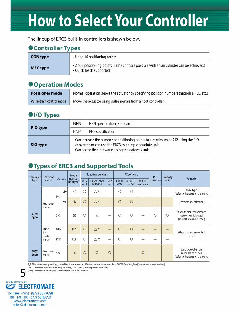
How to Select Your ControllerController Types
CON type • Up to 16 positioning points
MEC type • 2 or 3 positioning points (Same controls possible with an air cylinder can be achieved.) • Quick Teach supported
Operation ModesPositioner mode Normal operation (Move the actuator by specifying position numbers through a PLC, etc.)
Pulse-train control mode Move the actuator using pulse signals from a host controller.
I/O Types
PIO typeNPN NPN specification (Standard)
PNP PNP specification
SIO type• Can increase the number of positioning points to a maximum of 512 using the PIO converter, or can use the ERC3 as a simple absolute unit• Can access field networks using the gateway unit
Types of ERC3 and Supported Tools
Controller type
Operation mode I/O type
Model number
(I/O type)
Teaching pendant PC softwarePIO
converterGateway
unit RemarksCON-PTA
Quick TeachRCM-PST
SEP-PT
RCM-101-MW
RCM-101-USB
MEC PC software
CON type
Positioner mode
PIO
NPN NP *1 — — — — Basic type (Refer to the page on the right.)
PNP PN *1 — — — — Overseas specification
SIO SE — — When the PIO converter or
gateway unit is used (At least one is required.)
Pulse-train control mode
NPN PLN *1 — — — —When pulse-train control
is usedPNP PLP *1 — — — —
MEC type
Positioner mode SIO SE — — — —
Basic type when the Quick Teach is used
(Refer to the page on the right.)
: All functions are supported, : Limited functions are supported (Effective functions: Home return, Servo ON/OFF, JOG+, JOG-, Stop (Press and hold to reset the alarm)) *1 The SIO communication cable (for Quick Teach) (CB-PST-SIO050) must be purchased separately. (Note) The PIO converter and gateway unit cannot be used at the same time.
The lineup of ERC3 built-in controllers is shown below.
5ELECTROMATE
Toll Free Phone (877) SERVO98Toll Free Fax (877) SERV099
Sold & Serviced By:

PLC
100-VAC power supply
24-VDC power supply
Teaching pendant CON-PTAPC software
ERC3
System configuration
Quick Teach
100/200-VAC power supply
ERC3
System configuration
The basic types of ERC3 built-in controllers are listed below. Select one of the following types for any standard application.
➀ Basic type
➁ Basic type when the Quick Teach is used
ERC3
ERC3
Quick Teach (Refer to P. 7 and 51.)
Controller type CON type (Up to 16 positioning points)
Operation mode Positioner mode
I/O type PIO type
Controller type MEC type (2 or 3 positioning points)
Operation mode Positioner mode
I/O type SIO type
6ELECTROMATE
Toll Free Phone (877) SERVO98Toll Free Fax (877) SERV099
Sold & Serviced By:
7
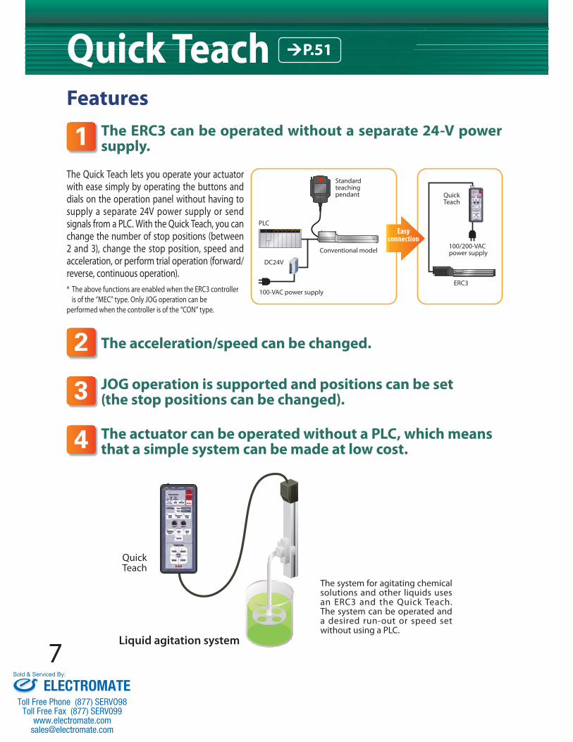
FeaturesThe ERC3 can be operated without a separate 24-V power supply.
The acceleration/speed can be changed.
JOG operation is supported and positions can be set (the stop positions can be changed).
The actuator can be operated without a PLC, which means that a simple system can be made at low cost. 4
3
2
1The Quick Teach lets you operate your actuator with ease simply by operating the buttons and dials on the operation panel without having to supply a separate 24V power supply or send signals from a PLC. With the Quick Teach, you can change the number of stop positions (between 2 and 3), change the stop position, speed and acceleration, or perform trial operation (forward/reverse, continuous operation).* The above functions are enabled when the ERC3 controller is of the “MEC” type. Only JOG operation can be performed when the controller is of the “CON” type.
ERC3
Quick Teach
100/200-VAC power supply
PLC
DC24V
100-VAC power supply
Standard teaching pendant
Easy connection
Conventional model
Quick Teach
The system for agitating chemical solutions and other liquids uses an ERC3 and the Quick Teach. The system can be operated and a desired run-out or speed set without using a PLC.
Liquid agitation system
Quick Teach P.51
ELECTROMATEToll Free Phone (877) SERVO98
Toll Free Fax (877) SERV099www.electromate.com
Sold & Serviced By:

Explanation of TermsFWD POS
Names of movements
(End position)middle middle
FWD BackActual movement
(Home position)
BACK POS
(middle position)
I recommend using the Quick Teach
if you want to operate your ERC3
right away.
8
Explanation of the Operation Panel
Press this button (and hold it for at least 1 second) to switch the number of positions between 2 and 3.
STOP POS NUM buttonUse this button to switch between modes 1 and 2 below: 1. Acceleration/speed2. Acceleration/speed/position
TEACH MODE button
Test run Use buttons in this area to actually move the actuator and check the saved operation.
In a 2-position travel, the actuator movesfrom the BACK position to the FWD position.In a 3-position travel, the actuator movesfrom the BACK position to the middle position, then to the FWD position.
The actuator returns to the home position.
Stops the above operation.
In a 2-position travel, the actuator movesback and forth between the FWD andBACK positions. In a 3-position travel, the actuator repeats its movement from the BACK position, middle position, FWD position, then BACK position.
FWD button
BACK button
STOP button
RUN button
Switch to a desired movement (among the following types): FWD POS: The actuator moves toward the end position. BACK POS: The actuator moves toward the home position. MIDDLE POS: The actuator moves toward the middle position.
buttons
FWD POS
MIDDLE POS
BACK POS/ /
Acceleration/Deceleration and Speed Settings Use buttons in this area to set how you want the actuator to move.
/ knobsYou can turn these knobs to change the actuator speed and acceleration within a range of 1% to 100% of the maximum speed and rated acceleration/deceleration, respectively. * The minimum speed may not be 1% of the maximum speed. For the minimum speed, refer to the operation manual.
ACCEL SPEED
/ buttons
Use this button to turn on/off the motor power.
Use these buttons to jog the actuator in the negative and positive directions.
SERVO ON/OFF button
JOG- JOG+
Pressing this button saves the speed, acceleration and position adjusted above.
SAVE button
When the actuator is started, home return is performed first to confirm the coordinate position of 0mm.
HOME buttonPressing this button disables the operation and all inputs from the operation panel buttons. It also enables PIO commands to the ERC3.
AUTO buttonMANUAL buttonPress this button (and hold it for at least 1 second) to set the acceleration/speed or perform a test run.
ELECTROMATEToll Free Phone (877) SERVO98
Toll Free Fax (877) SERV099www.electromate.com
Sold & Serviced By:

9
Quick Teach P.51
Operation MethodChanging the acceleration/speed
Changing the position
Performing test run (continuous operation)
➊ Press and hold the MANUAL button. ➋ Press the HOME button. ➌ Confirm that the Accel & Speed LED is lit. ➍ Press the button corresponding to the stop position (FWD POS/MIDDLE POS/BACK POS) where you want to change the acceleration/speed. * The MIDDLE POS button is available when the actuator is stopping at three positions.
➎ Turn the Accel/Speed knobs. * You can use the knobs to change the acceleration and speed within a range of 1% to 100% of the rated acceleration/deceleration and maximum speed, respectively. The minimum speed may not be 1% of the maximum speed, depending on the actuator. Refer to the operation manual for the minimum speed.
➏ Press the SAVE button.
➊ Press and hold the MANUAL button. ➋ Press the HOME button. ➌ Press the RUN button. * The actuator will move back and forth between the "forward position and back position" if it has been set to stop at two positions. The actuator will move repeatedly in the sequence of "forward position ➞ middle position ➞ back position ➞ forward position" if it has been set to stop at three positions.
➍ Press the STOP button to stop the operation.
➊ Press and hold the MANUAL button. ➋ Press the HOME button. ➌ Press the STOP POS NUM button and determine the number of stop positions. ➍ Press the TEACH MODE. (Both the Accel & Speed LED and Position LED should illuminate.) ➎ Press the button corresponding to the stop position (FWD POS/MIDDLE POS/BACK POS) where you want to change the position. * The MIDDLE POS button is available when the actuator is stopping at three positions.
➏ Move the actuator to a desired position. * You can jog the actuator or turn off the servo and move the actuator by hand.
➐ Press the SAVE button. * Exercise caution because the conditions of the Accel/Speed knobs will also be saved together with the position.
➐
➏
➎➍
➌
➋➊
➏
➎
➍
➌
➋➊
➊➋
➍
➌
ELECTROMATEToll Free Phone (877) SERVO98
Toll Free Fax (877) SERV099www.electromate.com
Sold & Serviced By:

10
Inkjet printer system Component palletizing system
Product life testing system Work part alignment system
Slider type
Rod type
This system prints on components using an inkjet printer. The ERC3 is used to move components. Since the ERC3 can operate at a constant speed, stable printing quality can be achieved.
This ERC3-based system palletizes automobile components. Two axes are arranged separately to pick components and place them onto the pallet. The takt time can be reduced by performing approach and return at high speed and placement at low speed.
This ERC3-based system conducts life testing on electronic equipment. The push speed and force can be changed according to the product.
Cardboard boxes transported on the conveyor are pushed to one side and aligned.
Printer headInkjet printer
Application Examples
ELECTROMATEToll Free Phone (877) SERVO98
Toll Free Fax (877) SERV099www.electromate.com
Sold & Serviced By:
11
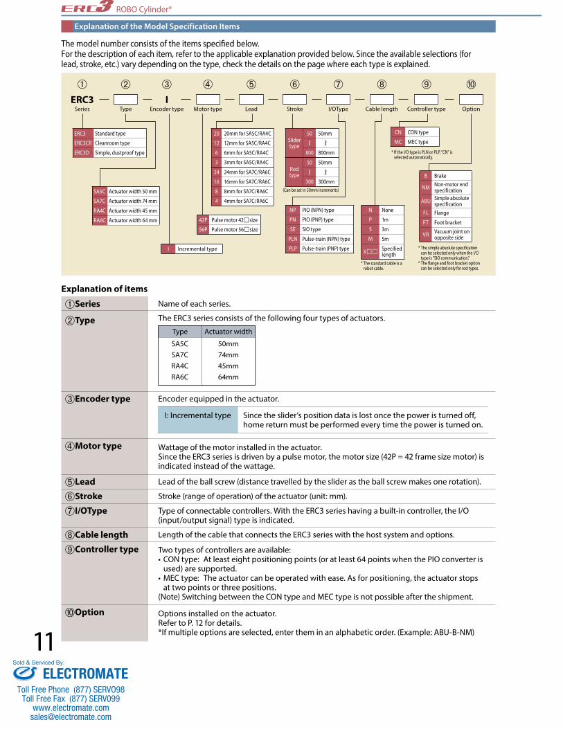
Explanation of the Model Specification Items
The model number consists of the items specified below. For the description of each item, refer to the applicable explanation provided below. Since the available selections (for lead, stroke, etc.) vary depending on the type, check the details on the page where each type is explained.
Explanation of items
➀Series Name of each series.
➁Type
➂Encoder type Encoder equipped in the actuator.
The ERC3 series consists of the following four types of actuators.
➃Motor type Wattage of the motor installed in the actuator. Since the ERC3 series is driven by a pulse motor, the motor size (42P = 42 frame size motor) is indicated instead of the wattage.
➄Lead Lead of the ball screw (distance travelled by the slider as the ball screw makes one rotation).
➅Stroke Stroke (range of operation) of the actuator (unit: mm).
➆I/OType Type of connectable controllers. With the ERC3 series having a built-in controller, the I/O (input/output signal) type is indicated.
➇Cable length Length of the cable that connects the ERC3 series with the host system and options.
Options installed on the actuator. Refer to P. 12 for details. *If multiple options are selected, enter them in an alphabetic order. (Example: ABU-B-NM)
➈Controller type
➉Option
Two types of controllers are available: • CON type: At least eight positioning points (or at least 64 points when the PIO converter is used) are supported. • MEC type: The actuator can be operated with ease. As for positioning, the actuator stops at two points or three positions. (Note) Switching between the CON type and MEC type is not possible after the shipment.
Actuator widthType
SA5CSA7CRA4CRA6C
50mm74mm45mm64mm
I: Incremental type Since the slider’s position data is lost once the power is turned off, home return must be performed every time the power is turned on.
ROBO Cylinder®
20 20mm for SA5C/RA4C
12 12mm for SA5C/RA4C
6 6mm for SA5C/RA4C
3 3mm for SA5C/RA4C
24 24mm for SA7C/RA6C
16 16mm for SA7C/RA6C
8 8mm for SA7C/RA6C
4 4mm for SA7C/RA6C
ERC3Series Type Motor type Stroke Controller type OptionLead I/OType Cable length
IEncoder type
ERC3 Standard type
ERC3CR Cleanroom type
ERC3D Simple, dustproof type
SA5C Actuator width 50 mm
SA7C Actuator width 74 mm
RA4C Actuator width 45 mm
RA6C Actuator width 64 mm 42P Pulse motor 42size
56P Pulse motor 56size
N None
P 1m
S 3m
M 5m
X Specified length
B Brake
NM Non-motor end specification
ABU Simple absolute specification
FL Flange
FT Foot bracket
VR Vacuum joint on opposite side
NP PIO (NPN) type
PN PIO (PNP) type
SE SIO type
PLN Pulse-train (NPN) type
PLP Pulse-train (PNP) typeI Incremental type
(Can be set in 50mm increments)
* If the I/O type is PLN or PLP, "CN" is selected automatically.
* The simple absolute specification can be selected only when the I/O type is "SIO communication." * The flange and foot bracket option can be selected only for rod types.
* The standard cable is a robot cable.
➀ ➁ ➂ ➃ ➄ ➅ ➆ ➇ ➉➈
Slider type
50 50mm
800 800mm
Rod type
50 50mm
300 300mm
CN CON type
MC MEC type
ELECTROMATEToll Free Phone (877) SERVO98
Toll Free Fax (877) SERV099www.electromate.com
Sold & Serviced By:

12
Actuator Options
75
11
34±0.1
4-ø6.6, bored 4-ø6.6, bored4-C1
34±0
.144
.56.
510
60±0.2
ERC3-RA4C type
71
17±0.1
2-ø6.6, bored4-ø4.5, boredDepth 8, counterbored depth 4.5
4-C1
10±0
0.5
1020
34±0.157±0.2
ERC3-RA4C type
99
14
50±0.2
4-ø9, bored 4-ø9, bored4-C1
50±0
.263
.58.
512
82±0.2
ERC3-RA6C type
957925
2-ø9 , bored through
2-ø6.5, bored through Depth 11, counterbored depth 7
4-C1
4-C1
12.5
2512
ERC3-RA6C type
Applicable models
Applicable models
Applicable models
Applicable models
Applicable models
Applicable models
Description
Description
Description
Description
Description
Description
All modelsA mechanism to hold the slider in place when the actuator is used vertically, so that it will not drop and damage the work part, etc., when the power or servo is turned off.
All modelsSelect this option if you want to change the home position of the actuator slider or rod from the normal position (motor side) to the front side.
ERC3-RA4C/RA6CA bracket used to secure a rod actuator from the actuator side. The flange can be purchased separately later on.
ERC3-RA4C/RA6CThis bracket is used to affix the rod type with bolts from above the actuator. The bracket can be purchased separately later on.
ERC3CR-SA5C/SA7CUnder the standard specification, the vacuum joint is installed on the left side of the actuator as viewed from the motor. When this option is selected, the position of this joint is moved to the right side (opposite side).
All modelsThis option is used to allow the actuator to operate without returning home first when the power is turned on. It can be selected only when the I/O type is "SIO communication (SE)." * The simple absolute battery is installed in the PIO converter (refer to P. 45), so the separately sold PIO converter of simple absolute specification is required.
Brake Model number: B
Non-motor end specification Model number: NM
Simple absolute specification Model number: ABU
Flange Model number: FL
Foot bracket Model number: FT
Vacuum joint on opposite side Model number: VR
ROBO Cylinder®
ELECTROMATEToll Free Phone (877) SERVO98
Toll Free Fax (877) SERV099www.electromate.com
Sold & Serviced By:
13
ROBO Cylinder®
2. Acceleration/Deceleration
3. Duty
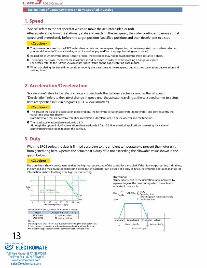
"Acceleration" refers to the rate of change in speed until the stationary actuator reaches the set speed. "Deceleration" refers to the rate of change in speed until the actuator traveling at the set speed comes to a stop. Both are specified in "G" in programs (0.3 G = 2940 mm/sec2).
<Caution>➊ The greater the value of acceleration (deceleration), the faster the actuator accelerates (decelerates) and consequently the travel time becomes shorter. Note, however, that an excessively higher acceleration (deceleration) is a cause of error and malfunction.
➋ The rated acceleration (deceleration) is 0.3 G. Although the upper limit of acceleration (deceleration) is 1 G (or 0.5 G in a vertical application), increasing the value of acceleration/deceleration reduces the payload.
With the ERC3 series, the duty is limited according to the ambient temperature to prevent the motor unit from generating heat. Operate the actuator at a duty ratio not exceeding the allowable value shown in the graph below.
<Caution>The duty limits shown below assume that the high-output setting of the controller is enabled. If the high-output setting is disabled, the payload and maximum speed become lower, but the actuator can be used at a duty of 100%. Refer to the operation manual for information on how to change the high-output setting.
[Duty ratio]"Duty ratio" refers to the utilization ratio indicated by a percentage of the time during which the actuator operates in one cycle.
D= TM
×100(%) TM+TR
D: DutyTM: Operating time (including push-motion operation) TR: Stationary timeSpeed
Acceleration Constant speed
Operating time TM
Duration of 1 cycle
Stationary time TR
Deceleration Stationary
1. Speed"Speed" refers to the set speed at which to move the actuator slider (or rod). After accelerating from the stationary state and reaching the set speed, the slider continues to move at that speed until immediately before the target position (specified position) and then decelerates to a stop.
<Caution>➊ The pulse motors used in the ERC3 series change their maximum speed depending on the transported mass. When selecting your model, refer to "Correlation diagrams of speed vs. payload" (on the page featuring each model).
➋ Regardless of whether the stroke is short or long, the set speed may not be reached if the travel distance is short. ➌ The longer the stroke, the lower the maximum speed becomes in order to avoid reaching a dangerous speed. For details, refer to the "Stroke vs. Maximum Speed" table on the page featuring each model.
➍ When calculating the travel time, consider not only the travel time at the set speed, but also the acceleration, deceleration and settling times.
Explanations of/Cautionary Notes on Items Specified in Catalog
Model Duration of 1 cycle (TM + TR)SA5C/RA4C 15 minutes or lessSA7C/RA6C 10 minutes or less
The duration of one cycle shall be assumed as follows:
Notes:Do not operate the actuator at a duty ratio exceeding the allowable value. If the actuator is operated at a duty ratio exceeding the allowable value, the life of the capacitor used in the controller will become shorter.
0 5 10 15 20 25 30 35 4029
Duty (%)
Ambient temperature (°C) (%)
80
70
60
50
40
Standard type
Cleanroom type, Simple, dustproof type
50%
40%
ELECTROMATEToll Free Phone (877) SERVO98
Toll Free Fax (877) SERV099www.electromate.com
Sold & Serviced By:
14
ROBO Cylinder®
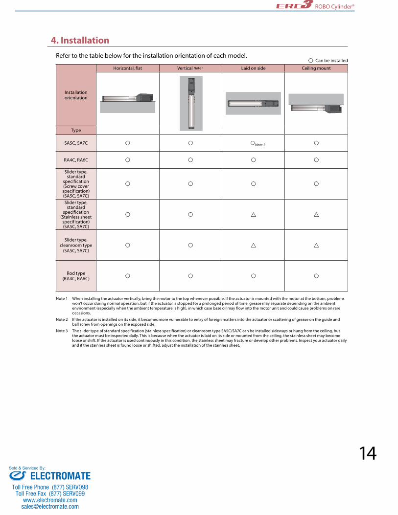
4. InstallationRefer to the table below for the installation orientation of each model.
Note 1 When installing the actuator vertically, bring the motor to the top whenever possible. If the actuator is mounted with the motor at the bottom, problems won’t occur during normal operation, but if the actuator is stopped for a prolonged period of time, grease may separate depending on the ambient environment (especially when the ambient temperature is high), in which case base oil may flow into the motor unit and could cause problems on rare occasions.
Note 2 If the actuator is installed on its side, it becomes more vulnerable to entry of foreign matters into the actuator or scattering of grease on the guide and ball screw from openings on the exposed side.
Note 3 The slider type of standard specification (stainless specification) or cleanroom type SA5C/SA7C can be installed sideways or hung from the ceiling, but the actuator must be inspected daily. This is because when the actuator is laid on its side or mounted from the ceiling, the stainless sheet may become loose or shift. If the actuator is used continuously in this condition, the stainless sheet may fracture or develop other problems. Inspect your actuator daily and if the stainless sheet is found loose or shifted, adjust the installation of the stainless sheet.
Installation orientation
Horizontal, flat Vertical Note 1 Laid on side Ceiling mount
Type
SA5C, SA7C Note 2
RA4C, RA6C
Slider type, standard
specification (Screw cover specification) (SA5C, SA7C)
Slider type, standard
specification (Stainless sheet specification) (SA5C, SA7C)
Slider type, cleanroom type
(SA5C, SA7C)
Rod type(RA4C, RA6C)
: Can be installed
ELECTROMATEToll Free Phone (877) SERVO98
Toll Free Fax (877) SERV099www.electromate.com
Sold & Serviced By:
15
ROBO Cylinder®
50
53.5
68.7
299.9~1049.9
Stroke50~800
Unit: mm
③Cable length
*Refer to P. 44 for maintenance cables.
Type Cable symbolStandard price
PIO type SIO type
Standard type (Robot cable)
P (1m) — —S (3m) — —M (5m) — —
Special length X06(6m)~X10(10m) — —
①Stroke
Stroke (mm)
Standard price
450 —500 —550 —600 —650 —700 —750 —800 —
Stroke (mm)
Standard price
50 —100 —150 —200 —250 —300 —350 —400 —
Name Option code See page Standard priceBrake B P12 —Non-motor end specification NM P12 —
Vacuum joint on opposite side VR P12 —
Simple absolute specification ABU P12 — (*)
00 200 400
Speed (mm/s)600 800 1000 1200 1400 200 400 600 800 1000 1200 14000
5
10
15
20
25
0
Speed (mm/s)
2
4
6
8
10
12
14
Paylo
ad (k
g)
Paylo
ad (k
g)
Lead 3Lead 3
Lead 6Lead 6
Lead 12Lead 12Lead 20Lead 20
Lead 6Lead 6
Lead 12Lead 12 Lead 20Lead 20
HorizontalHorizontal VerticalVertical
5
7996.5
18
Lead 3Lead 3
2.5
0.50.5 0.50.5
115.5
The values below are based on operation at 0.3 G.The values below are based on operation at 0.3 G.
High-output setting enabled (Factory default)
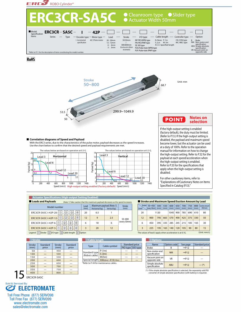
ERC3CR-SA5C Model Specification Items
ERC3CRSeries
SA5CType
42PMotor type Lead Stroke OptionCable lengthI/O type
42Pulse motorI: Incremental specification
NP: PIO (NPN) typePN: PIO (PNP) typeSE: SIO typePLN: Pulse-train (NPN) type PLP: Pulse-train (PNP) type
CN: CON typeMC: MEC type
20 : 20mm 12 : 12mm 6 : 6mm 3 : 3mm
*Refer to P.11 for the description of items constituting the model number.
Cleanroom type Slider typeActuator Width 50mm
50:50mm
800:800mm(Can be set in 50mm
increments)
B : Brake NM : Non-motor end specification ABU: Simple absolute specificationVR: Vacuum joint on opposite side
N: None P: 1mS: 3 m M: 5mX: Specified length
Controller type
IEncoder type
Correlation diagrams of Speed and Payload With the ERC3 series, due to the characteristics of the pulse motor, payload decreases as the speed increases. Use the chart below to confirm that the desired speed and payload requirements are met.
Notes on selection
If the high-output setting is enabled (factory default), the duty must be limited. (Refer to P.13.) If the high-output setting is disabled, the payload and maximum speed become lower, but the actuator can be used at a duty of 100%. Refer to the operation manual for information on how to change the high-output setting. Refer to P.32 for the payload at each speed/acceleration when the high-output setting is enabled.Refer to P.33 for the specifications that apply when the high-output setting is disabled.
For other cautionary items, refer to “Explanations of/Cautionary Notes on Items Specified in Catalog (P.13).”
POINT
Model number Lead(mm)
Maximum payload (Note 1) Stroke(mm)Horizontal (kg) Vertical (kg)
ERC3CR-SA5C-I-42P-20- ➀ - ➁ - ➂ - ➃ 20 6.5 1
50~800(every 50mm)
ERC3CR-SA5C-I-42P-12- ➀ - ➁ - ➂ - ➃ 12 9 2.5
ERC3CR-SA5C-I-42P-6- ➀ - ➁ - ➂ - ➃ 6 18 6
ERC3CR-SA5C-I-42P-3- ➀ - ➁ - ➂ - ➃ 3 20 12
Legend ➀ Stroke ➁ I/O type ➂ Cable length ➃ Option (Unit: mm/s)
Leads and Payloads (Note 1) Take caution that the maximum payload decreases as the speed increases.
StrokeLead
50~450(every 50mm)
500(mm)
550(mm)
600(mm)
650(mm)
700(mm)
750(mm)
800(mm)
Suction amount(Nl/min)
20 1120 1045 900 785 690 610 80
12 900 795 665 570 490 425 375 330 50
6 450 395 335 285 245 215 185 165 30
3 225 195 165 140 120 105 90 80 15
Stroke and Maximum Speed/Suction Amount by LeadActuator Specifications (High-output Setting Enabled)
ERC3CR-SA5C
(*) If the simple absolute specification is selected, the separately sold PIO converter of simple absolute specification (with battery) is required.
The values of lead 3 apply when acceleration is at 0.1G.
④Options
ELECTROMATEToll Free Phone (877) SERVO98
Toll Free Fax (877) SERV099www.electromate.com
Sold & Serviced By:

16
ROBO Cylinder®
39
5055.3
43.553
.568.7
6 20 632
17.2
32.5
Opposite side
5
Detail Y
6.5
4.5
ø4.5
5
Detail view of mounting hole
ø8
*4 Outer diameter of suction joint tube: ø6
24
2050C×100P
62AG7 126.9
26B×100P
Y
3Stroke
3
ø40 (range of rotation)
105.7L
90 34.2
32 43.2
ME
ME (*2)
Home
K20
SE
19±0.02
30 43
15.5 9 15.5
26(ø4H7 pitch ±0.02)
2-ø4,H7 depth 6 4-M4 depth 9
27.2
21
Teaching port
Cable joint connector (*1)
148.2
The overall length of the brake speci�cation is 42.5mm longer than the standard speci�cation and its mass is 0.4 kg heavier.
External view of the brake speci�cation
105.742.5
O�set reference position for moments (*3)
4+0.
012
0
Standard
Suction joint (*4)
H - Oblong hole penetrating through one wall (Maximum insertion depth 7 from the bottom of the base)
D-M4 depth 9
J (Pitch between ø4H7 and oblong hole)
F-ø4.5, through ø8 counterbored, depth 5.5 (from the opposite side)
2 -ø4H7 penetrating through one wall (Maximum insertion depth 7 from the bottom of the base)
*1 Connect the power & I/O cable. Refer to P.44 for details on this cable SE: Stroke End ME: Mechanical End
*2 The slider moves to the ME during home return, so pay attention to possible contact with surrounding structures.
*3 Reference position is used when calculating the Ma and Mc moments
Dimensional Drawings
CAD drawings can be downloaded from the website. www.intelligentactuator.com
2D CAD2D
CAD
②I/O typeControllers (Built into the Actuator)
With the ERC3 series, one of the following five types of built-in controllers can be selected depending on the external input/output (I/O) type. Select the type that meets your purpose.
Name External view Model number FeaturesMaximum number of
positioning pointsInput power
Power supply capacity
Standard price
Reference page
PIO type (NPN specification) ERC3CR-SA5C-I-42P---NP--
Simple control type accommodating up to 16 positioning points
16
DC24V
High-output setting
enabled: 3.5A rated 4.2A
max.
High-output setting
disabled: 2.2A
— P35
PIO type (PNP specification) ERC3CR-SA5C-I-42P---PN--
I/O type supporting inputs/outputs of the
PNP specification often used overseas
16
SIO type ERC3CR-SA5C-I-42P---SE--High-function type
accommodating up to 512 positioning points (PIO converter is used)
512
Pulse-train type (NPN
specification)ERC3CR-SA5C-I-42P---PLN--
Pulse-train input type supporting the NPN
specification −
Pulse-train type (PNP
specification)ERC3CR-SA5C-I-42P---PLP--
Pulse-train input type supporting the PNP
specification −
L
L
Ma MaMb Mc Mc
(*1) The specification in [ ] applies when the lead is 20 mm.(*2) Based on 5,000 km of traveling life.
Item Descr ipt ionDrive system Ball screw ø10 mm, rolled C10Positioning repeatability (*1) ± 0.02 mm [± 0.03 mm]Lost motion 0.1 mm or lessStatic allowable load moment Ma: 29.4 N•m, Mb: 42.0 N•m, Mc: 60.5 N•mDynamic allowable load moment (*2) Ma: 7.1 N•m, Mb: 10.2 N•m, Mc: 14.7 N•m
Overhang load lengths 150mm or less in Ma direction, 150 mm or less in Mb and Mc directions
Ambient operation temperature, humidity 0 to 40˚C, 85% RH or less (Non-condensing)
Allowable load moment directionsOverhang load lengths
Stroke 50 100 150 200 250 300 350 400 450 500 550 600 650 700 750 800L 299.9 349.9 399.9 449.9 499.9 549.9 599.9 649.9 699.9 749.9 799.9 849.9 899.9 949.9 999.9 1049.9A 73 100 100 200 200 300 300 400 400 500 500 600 600 700 700 800 B 0 0 0 1 1 2 2 3 3 4 4 5 5 6 6 7 C 0 0 1 1 2 2 3 3 4 4 5 5 6 6 7 7 D 4 4 4 6 6 8 8 10 10 12 12 14 14 16 16 18 F 4 4 6 6 8 8 10 10 12 12 14 14 16 16 18 18 G 166 216 266 316 366 416 466 516 566 616 666 716 766 816 866 916H 0 1 1 1 1 1 1 1 1 1 1 1 1 1 1 1J 0 85 85 185 185 285 285 385 385 485 485 585 585 685 685 785K 194.2 244.2 294.2 344.2 394.2 444.2 494.2 544.2 594.2 644.2 694.2 744.2 794.2 844.2 894.2 944.2
Mass (kg) 1.6 1.8 2.0 2.1 2.3 2.5 2.6 2.8 3.0 3.1 3.3 3.5 3.6 3.8 4.0 4.1
Dimensions and Mass by StrokeActuator specificaton
ERC3CR-SA5C
ELECTROMATEToll Free Phone (877) SERVO98
Toll Free Fax (877) SERV099www.electromate.com
Sold & Serviced By:

ROBO Cylinder®
17 ERC3CR-SA7C
73
71
85
372.2~1122.2
Stroke50~800 Unit: mm
Correlation diagrams of Speed and Payload With the ERC3 series, due to the characteristics of the pulse motor, payload decreases as the speed increases. Use the chart below to confirm that the desired speed and payload requirements are met.
0 200 400 600 800 1000 1200 14000
Speed (mm/s)
5
10
15
20
25
0 200 400 600 800 1000 1200 14000
Speed (mm/s)
51015202530
50454035
Paylo
ad (k
g)
Paylo
ad (k
g)
Lead 8Lead 8
Lead 16Lead 16
Lead 24Lead 24
Lead 4Lead 4
Lead 8Lead 8
Lead 16Lead 16Lead 24Lead 24
1 1
22
14
6
33.54.5
HorizontalHorizontal VerticalVerticalLead 4Lead 4
1818
44 4422
1717
Type Cable symbolStandard price
PIO type SIO type
Standard type (Robot cable)
P (1m) — —S (3m) — —M (5m) — —
Special length X06(6m)~X10(10m) — —
(*) If the simple absolute specification is selected, the separately sold PIO converter of simple absolute specification (with battery) is required.
Name Option code See page Standard priceBrake B P12 —Non-motor end specification NM P12 —
Vacuum joint on opposite side VR P12 —
Simple absolute specification ABU P12 — (*)
Notes on selection
If the high-output setting is enabled (factory default), the duty must be limited. (Refer to P.13.) If the high-output setting is disabled, the payload and maximum speed become lower, but the actuator can be used at a duty of 100%. Refer to the operation manual for information on how to change the high-output setting. Refer to P.32 for the payload at each speed/acceleration when the high-output setting is enabled.Refer to P.33 for the specifications that apply when the high-output setting is disabled.
For other cautionary items, refer to “Explanations of/Cautionary Notes on Items Specified in Catalog (P.13).”
POINT
The values below are based on operation at 0.3 G.The values below are based on operation at 0.3 G.
High-output setting enabled (Factory default)
③Cable length
*Refer to P. 44 for maintenance cables.
①Stroke
ERC3CR-SA7C Model Specification Items
ERC3CRSeries
SA7CType
56PMotor type Lead Stroke OptionCable lengthI/O type
56Pulse motorI: Incremental specification
NP: PIO (NPN) typePN: PIO (PNP) typeSE: SIO typePLN: Pulse-train (NPN) type PLP: Pulse-train (PNP) type
CN: CON typeMC: MEC type
24 : 24mm 16 : 16mm 8 : 8mm 4 : 4mm
Cleanroom type Slider typeActuator Width 73mm
50:50mm
800:800mm(Can be set in 50mm
increments)
B : Brake NM : Non-motor end specification ABU: Simple absolute specificationVR: Vacuum joint on opposite side
N: None P: 1mS: 3 m M: 5mX: Specified length
Controller type
IEncoder type
*Refer to P.11 for the description of items constituting the model number.
Legend ➀ Stroke ➁ I/O type ➂ Cable length ➃ Option
Leads and Payloads (Note 1) Take caution that the maximum payload decreases as the speed increases. Stroke and Maximum Speed/Suction Amount by LeadActuator Specifications (High-output Setting Enabled)
Model number Lead(mm)
Maximum payload (Note 1) Stroke(mm)Horizontal (kg) Vertical (kg)
ERC3CR-SA7C-I-56P-24- ➀ - ➁ - ➂ - ➃ 24 17 3
50~800(every 50mm)
ERC3CR-SA7C-I-56P-16- ➀ - ➁ - ➂ - ➃ 16 35 6
ERC3CR-SA7C-I-56P-8- ➀ - ➁ - ➂ - ➃ 8 40 14
ERC3CR-SA7C-I-56P-4- ➀ - ➁ - ➂ - ➃ 4 45 22
(Unit: mm/s)
StrokeLead
50~550(every 50mm)
600(mm)
650(mm)
700(mm)
750(mm)
800(mm)
Suction amount(Nl/min)
24 1200 1155 1010 890 790 90
16 980<840>
865<840> 750 655 580 515 70
8 490 430 375 325 290 255 40
4 210 185 160 145 125 30
④Options
Stroke (mm)
Standard price
50 —100 —150 —200 —250 —300 —350 —400 —
Stroke (mm)
Standard price
450 —500 —550 —600 —650 —700 —750 —800 —
The value inside < > indicates vertical usage.The values of lead 8 and lead 4 apply when acceleration is at 0.1G.
ELECTROMATEToll Free Phone (877) SERVO98
Toll Free Fax (877) SERV099www.electromate.com
Sold & Serviced By:

ROBO Cylinder®
Dimensional Drawings
CAD drawings can be downloaded from the website. www.intelligentactuator.com
2D CAD2D
CAD
Dimensional Drawings
CAD drawings can be downloaded from the website. www.intelligentactuator.com
18ERC3CR-SA7C
20 20 20 4-M5 depth 10
44.9
21
The overall length of the brake speci�cation is 51 mm longer than the standard speci�cation and its mass is 0.5 kg heavier.
000185.5
134.551
J (Pitch between ø4H7 and oblong hole)30C×100P
A 80 25.510 G 163.2
Y
B×100PE - ø4H7 penetrating through one wall (Maximum insertion depth 12 from the bottom of the base)
F-ø6, through ø9.5 counterbored, depth 11 (from the opposite side)
D-M5 depth 11Suction joint (*4)
3320.5
134.5KL
128 39.2
58.7
SEME ME
40
*4 Outer diameter of suction joint tube: ø8
43
7173
5771
85
488 32 8
25.5
52.5
32±0.02
50
39
49.5
5
ø9.5
ø6
12.5
5.5
6
Detail view of mounting hole
O�set reference position for moments
Opposite side
4 +
0.01
2
0
2-ø5, H7 depth 10
(ø5H7 pitch ±0.02)
ø46 (range of rotation)Stroke
Home
Standard
Detail Y
External view of the brake speci�cation
Teaching port
Cable joint connector (*1)
*1 Connect the power & I/O cable. Refer to P.44 for details on this cable SE: Stroke End ME: Mechanical End
*2 The slider moves to the ME during home return, so pay attention to possible contact with surrounding structures.
*3 Reference position is used when calculating the Ma and Mc moments
H - Oblong hole penetrating through one wall (Maximum insertion depth 12 from the bottom of the base)
②I/O typeControllers (Built into the Actuator)
With the ERC3 series, one of the following five types of built-in controllers can be selected depending on the external input/output (I/O) type. Select the type that meets your purpose.
Name External view Model number FeaturesMaximum number of
positioning pointsInput power
Power supply capacity
Standard price
Reference page
PIO type (NPN specification) ERC3CR-SA7C-I-56P---NP--
Simple control type accommodating up to 16 positioning points
16
DC24V
High-output setting
enabled: 3.5A rated 4.2A
max.
High-output setting
disabled: 2.2A
— P35
PIO type (PNP specification) ERC3CR-SA7C-I-56P---PN--
I/O type supporting inputs/outputs of the
PNP specification often used overseas
16
SIO type ERC3CR-SA7C-I-56P---SE--High-function type
accommodating up to 512 positioning points (PIO converter is used)
512
Pulse-train type (NPN
specification)ERC3CR-SA7C-I-56P---PLN--
Pulse-train input type supporting the NPN
specification −
Pulse-train type (PNP
specification)ERC3CR-SA7C-I-56P---PLP--
Pulse-train input type supporting the PNP
specification −
Dimensions and Mass by StrokeActuator specificaton
L
L
Ma MaMb Mc McAllowable load moment directions
Overhang load lengths
(*1) The specification in [ ] applies when the lead is 24 mm.(*2) Based on 5,000 km of traveling life.
Item Descr ipt ionDrive system Ball screw ø12 mm, rolled C10Positioning repeatability (*1) ± 0.02 mm [± 0.03 mm]Lost motion 0.1 mm or lessStatic allowable load moment Ma: 70.0 N•m, Mb: 100.0 N•m, Mc: 159.5 N•mDynamic allowable load moment (*2) Ma: 15.0 N•m, Mb: 21.4 N•m, Mc: 34.1 N•m
Overhang load lengths 150 mm or less in Ma direction, 150 mm or less in Mb and Mc directions
Ambient operation temperature, humidity 0 to 40˚C, 85% RH or less (Non-condensing)
Stroke 50 100 150 200 250 300 350 400 450 500 550 600 650 700 750 800L 372.2 422.2 472.2 522.2 572.2 622.2 672.2 722.2 772.2 822.2 872.2 922.2 972.2 1022.2 1072.2 1122.2A 0 100 100 200 200 300 300 400 400 500 500 600 600 700 700 800 B 0 0 0 1 1 2 2 3 3 4 4 5 5 6 6 7 C 1 1 2 2 3 3 4 4 5 5 6 6 7 7 8 8 D 4 6 6 8 8 10 10 12 12 14 14 16 16 18 18 20 E 2 3 3 3 3 3 3 3 3 3 3 3 3 3 3 3F 4 4 6 6 8 8 10 10 12 12 14 14 16 16 18 18 G 199 249 299 349 399 449 499 549 599 649 699 749 799 849 899 949H 0 1 1 1 1 1 1 1 1 1 1 1 1 1 1 1 J 0 85 85 185 185 285 285 385 385 485 485 585 585 685 685 785K 237.7 287.7 337.7 387.7 437.7 487.7 537.7 587.7 637.7 687.7 737.7 787.7 837.7 887.7 937.7 987.7
Mass (kg) 3.6 3.9 4.1 4.4 4.7 4.9 5.2 5.5 5.7 6.0 6.3 6.5 6.8 7.1 7.3 7.6
ELECTROMATEToll Free Phone (877) SERVO98
Toll Free Fax (877) SERV099www.electromate.com
Sold & Serviced By:

ROBO Cylinder®
19 ERC3D-SA5C
50
53.5
68.7
299.9~1049.9
Stroke50~800
Unit: mm
④Options
(Unit: mm/s)
Stroke
Lead50~450
(every 50mm)500(mm)
550(mm)
600(mm)
650(mm)
700(mm)
750(mm)
800(mm)
20 1120 1045 900 785 690 610
12 900 795 665 570 490 425 375 330
6 450 395 335 285 245 215 185 165
3 225 195 165 140 120 105 90 80
③Cable length
*Refer to P. 44 for maintenance cables.
Type Cable symbolStandard price
PIO type SIO type
Standard type (Robot cable)
P (1m) — —S (3m) — —M (5m) — —
Special length X06(6m)~X10(10m) — —
①Stroke
Stroke (mm)
Standard price
450 —500 —550 —600 —650 —700 —750 —800 —
Stroke (mm)
Standard price
50 —100 —150 —200 —250 —300 —350 —400 —
(*) If the simple absolute specification is selected, the separately sold PIO converter of simple absolute specification (with battery) is required.
The values of lead 3 apply when acceleration is at 0.1G.
Name Option code See page Standard priceBrake B P12 —Non-motor end specification NM P12 —
Simple absolute specification ABU P12 — (*)
Notes on selection
If the high-output setting is enabled (factory default), the duty must be limited. (Refer to P.13.) If the high-output setting is disabled, the payload and maximum speed become lower, but the actuator can be used at a duty of 100%. Refer to the operation manual for information on how to change the high-output setting. Refer to P.32 for the payload at each speed/acceleration when the high-output setting is enabled.Refer to P.33 for the specifications that apply when the high-output setting is disabled.
For other cautionary items, refer to “Explanations of/Cautionary Notes on Items Specified in Catalog (P.13).”
POINT
Model number Lead(mm)
Maximum payload (Note 1) Stroke(mm)Horizontal (kg) Vertical (kg)
ERC3D-SA5C-I-42P-20- ➀ - ➁ - ➂ - ➃ 20 6.5 1
50~800(every 50mm)
ERC3D-SA5C-I-42P-12- ➀ - ➁ - ➂ - ➃ 12 9 2.5
ERC3D-SA5C-I-42P-6- ➀ - ➁ - ➂ - ➃ 6 18 6
ERC3D-SA5C-I-42P-3- ➀ - ➁ - ➂ - ➃ 3 20 12
Legend ➀ Stroke ➁ I/O type ➂ Cable length ➃ Option
Leads and Payloads (Note 1) Take caution that the maximum payload decreases as the speed increases. Stroke and Maximum Speed by LeadActuator Specifications (High-output Setting Enabled)
ERC3D-SA5C ERC3D
Series
SA5CType
42PMotor type Lead Stroke OptionCable lengthI/O type
42Pulse motorI: Incremental specification
NP: PIO (NPN) typePN: PIO (PNP) typeSE: SIO typePLN: Pulse-train (NPN) type PLP: Pulse-train (PNP) type
CN: CON typeMC: MEC type
20 : 20mm 12 : 12mm 6 : 6mm 3 : 3mm
Simple, dustproof type Slider type Actuator Width 50mm
50:50mm
800:800mm(Can be set in 50mm
increments)
B : Brake NM : Non-motor end specification ABU: Simple absolute specification
N: None P: 1mS: 3 m M: 5mX: Specified length
Controller type
IEncoder type
Model Specification Items
00 200 400
Speed (mm/s)600 800 1000 1200 1400 200 400 600 800 1000 1200 14000
5
10
15
20
25
0
Speed (mm/s)
2
4
6
8
10
12
14
Paylo
ad (k
g)
Paylo
ad (k
g)
Lead 3Lead 3
Lead 6Lead 6
Lead 12Lead 12Lead 20Lead 20
Lead 6Lead 6
Lead 12Lead 12 Lead 20Lead 20
HorizontalHorizontal VerticalVertical
5
7996.5
18
Lead 3Lead 3
2.5
0.50.5 0.50.5
115.5
The values below are based on operation at 0.3 G.The values below are based on operation at 0.3 G.
High-output setting enabled (Factory default)
Correlation diagrams of Speed and Payload With the ERC3 series, due to the characteristics of the pulse motor, payload decreases as the speed increases. Use the chart below to confirm that the desired speed and payload requirements are met.
*Refer to P.11 for the description of items constituting the model number.
ELECTROMATEToll Free Phone (877) SERVO98
Toll Free Fax (877) SERV099www.electromate.com
Sold & Serviced By:

ROBO Cylinder®
Dimensional Drawings
CAD drawings can be downloaded from the website. www.intelligentactuator.com
2D CAD2D
CAD
Dimensional Drawings
CAD drawings can be downloaded from the website. www.intelligentactuator.com
20ERC3D-SA5C
39
5055.3
43.5
53.568
.7
6 20 632
5
Detail Y
6.5
4.5
ø4.5
5 J (Pitch between ø4H7 and oblong hole)2050C×100P
62AG7 126.9
26
B×100P2 - ø4H7 penetrating through one wall (Maximum insertion depth 7 from the bottom of the base)
D-M4 depth 9 F-ø4.5, through ø8 counterbored,
depth 5.5 (from the opposite side)
H - Oblong hole penetrating through one wall (Maximum insertion depth 7 from the bottom of the base)
Y
24
27.2
21
Teaching port
Cable joint connector (*1)
External view of the brake speci�cation
148.2105.742.5
Stroke318
394 32.2
105.7KL
ME SEME (*2)
15.5 9 15.5
26(ø4H7 pitch ±0.02)
4-M4 depth 9
30 43
2-ø4, H7 depth 6
19±0.02
Home
O�set reference position for moments (*3)
4 +
0.01
2
0
ø8
Detail view of mounting hole
The overall length of the brake speci�cation is 42.5 mm longer than the standard speci�cation and its mass is 0.4 kg heavier.
*1 Connect the power & I/O cable. Refer to P.44 for details on this cable SE: Stroke End ME: Mechanical End
*2 The slider moves to the ME during home return, so pay attention to possible contact with surrounding structures.
*3 Reference position is used when calculating the Ma and Mc moments
②I/O typeControllers (Built into the Actuator)
With the ERC3 series, one of the following five types of built-in controllers can be selected depending on the external input/output (I/O) type. Select the type that meets your purpose.
Name External view Model number FeaturesMaximum number of
positioning pointsInput power
Power supply capacity
Standard price
Reference page
PIO type (NPN specification) ERC3D-SA5C-I-42P---NP--
Simple control type accommodating up to 16 positioning points
16
DC24V
High-output setting
enabled: 3.5A rated 4.2A
max.
High-output setting
disabled: 2.2A
— P35
PIO type (PNP specification) ERC3D-SA5C-I-42P---PN--
I/O type supporting inputs/outputs of the
PNP specification often used overseas
16
SIO type ERC3D-SA5C-I-42P---SE--High-function type
accommodating up to 512 positioning points (PIO converter is used)
512
Pulse-train type (NPN
specification)ERC3D-SA5C-I-42P---PLN--
Pulse-train input type supporting the NPN
specification −
Pulse-train type (PNP
specification)ERC3D-SA5C-I-42P---PLP--
Pulse-train input type supporting the PNP
specification −
L
L
Ma MaMb Mc Mc
(*1) The specification in [ ] applies when the lead is 20 mm.(*2) Based on 5,000 km of traveling life.
Item Descr ipt ionDrive system Ball screw ø10 mm, rolled C10Positioning repeatability (*1) ± 0.02 mm [± 0.03 mm]Lost motion 0.1 mm or lessStatic allowable load moment Ma: 29.4 N•m, Mb: 42.0 N•m, Mc: 60.5 N•mDynamic allowable load moment (*2) Ma: 7.1 N•m, Mb: 10.2 N•m, Mc: 14.7 N•m
Overhang load lengths 150 mm or less in Ma direction, 150 mm or less in Mb and Mc directions
Ambient operation temperature, humidity 0 to 40˚C, 85% RH or less (Non-condensing)
Allowable load moment directionsOverhang load lengths
Stroke 50 100 150 200 250 300 350 400 450 500 550 600 650 700 750 800L 299.9 349.9 399.9 449.9 499.9 549.9 599.9 649.9 699.9 749.9 799.9 849.9 899.9 949.9 999.9 1049.9A 73 100 100 200 200 300 300 400 400 500 500 600 600 700 700 800 B 0 0 0 1 1 2 2 3 3 4 4 5 5 6 6 7 C 0 0 1 1 2 2 3 3 4 4 5 5 6 6 7 7 D 4 4 4 6 6 8 8 10 10 12 12 14 14 16 16 18 F 4 4 6 6 8 8 10 10 12 12 14 14 16 16 18 18 G 166 216 266 316 366 416 466 516 566 616 666 716 766 816 866 916H 0 1 1 1 1 1 1 1 1 1 1 1 1 1 1 1J 0 85 85 185 185 285 285 385 385 485 485 585 585 685 685 785K 194.2 244.2 294.2 344.2 394.2 444.2 494.2 544.2 594.2 644.2 694.2 744.2 794.2 844.2 894.2 944.2
Mass (kg) 1.6 1.8 2.0 2.1 2.3 2.5 2.6 2.8 3.0 3.1 3.3 3.5 3.6 3.8 4.0 4.1
Dimensions and Mass by StrokeActuator specificaton
ELECTROMATEToll Free Phone (877) SERVO98
Toll Free Fax (877) SERV099www.electromate.com
Sold & Serviced By:

ROBO Cylinder® ROBO Cylinder®
ERC3D-SA7C21
73
71
85
372.2~1122.2
Stroke50~800 Unit: mm
ERC3D-SA7C
③Cable length
*Refer to P. 44 for maintenance cables.
Type Cable symbolStandard price
PIO type SIO type
Standard type (Robot cable)
P (1m) — —S (3m) — —M (5m) — —
Special length X06(6m)~X10(10m) — —
①Stroke
Stroke (mm)
Standard price
450 —500 —550 —600 —650 —700 —750 —800 —
Stroke (mm)
Standard price
50 —100 —150 —200 —250 —300 —350 —400 —
(*) If the simple absolute specification is selected, the separately sold PIO converter of simple absolute specification (with battery) is required.
Name Option code See page Standard priceBrake B P12 —Non-motor end specification NM P12 —
Simple absolute specification ABU P12 — (*)
④Options
ERC3D-SA7C ERC3D
Series
SA7CType
56PMotor type Lead Stroke OptionCable lengthI/O type
56Pulse motorI: Incremental specification
NP: PIO (NPN) typePN: PIO (PNP) typeSE: SIO typePLN: Pulse-train (NPN) type PLP: Pulse-train (PNP) type
CN: CON typeMC: MEC type
24 : 24mm 16 : 16mm 8 : 8mm 4 : 4hmm
Simple, dustproof type Slider type Actuator Width 73mm
50:50mm
800:800mm(Can be set in 50mm
increments)
B : Brake NM : Non-motor end specification ABU: Simple absolute specification
N: None P: 1mS: 3 m M: 5mX: Specified length
Controller type
IEncoder type
Model Specification Items
*Refer to P.11 for the description of items constituting the model number.
0 200 400 600 800 1000 1200 14000
Speed (mm/s)
5
10
15
20
25
0 200 400 600 800 1000 1200 14000
Speed (mm/s)
51015202530
50454035
Paylo
ad (k
g)
Paylo
ad (k
g)
Lead 8Lead 8
Lead 16Lead 16
Lead 24Lead 24
Lead 4Lead 4
Lead 8Lead 8
Lead 16Lead 16Lead 24Lead 24
1 1
22
14
6
33.54.5
HorizontalHorizontal VerticalVerticalLead 4Lead 4
1818
44 4422
1717
The values below are based on operation at 0.3 G.The values below are based on operation at 0.3 G.
High-output setting enabled (Factory default)
Correlation diagrams of Speed and Payload With the ERC3 series, due to the characteristics of the pulse motor, payload decreases as the speed increases. Use the chart below to confirm that the desired speed and payload requirements are met.
Notes on selection
If the high-output setting is enabled (factory default), the duty must be limited. (Refer to P.13.) If the high-output setting is disabled, the payload and maximum speed become lower, but the actuator can be used at a duty of 100%. Refer to the operation manual for information on how to change the high-output setting. Refer to P.32 for the payload at each speed/acceleration when the high-output setting is enabled.Refer to P.33 for the specifications that apply when the high-output setting is disabled.
For other cautionary items, refer to “Explanations of/Cautionary Notes on Items Specified in Catalog (P.13).”
POINT
Model number Lead(mm)
Maximum payload (Note 1) Stroke(mm)Horizontal (kg) Vertical (kg)
ERC3D-SA7C-I-56P-24- ➀ - ➁ - ➂ - ➃ 24 17 3
50~800(every 50mm)
ERC3D-SA7C-I-56P-16- ➀ - ➁ - ➂ - ➃ 16 35 6
ERC3D-SA7C-I-56P-8- ➀ - ➁ - ➂ - ➃ 8 40 14
ERC3D-SA7C-I-56P-4- ➀ - ➁ - ➂ - ➃ 4 45 22
Legend ➀ Stroke ➁ I/O type ➂ Cable length ➃ Option
Leads and Payloads (Note 1) Take caution that the maximum payload decreases as the speed increases. Stroke and Maximum Speed by LeadActuator Specifications (High-output Setting Enabled)
(Unit: mm/s)
StrokeLead
50~550(every 50mm)
600(mm)
650(mm)
700(mm)
750(mm)
800(mm)
24 1200 1155 1010 890 790
16 980<840>
865<840> 750 655 580 515
8 490 430 375 325 290 255
4 210 185 160 145 125The value inside < > indicates vertical usage.The values of lead 8 and lead 4 apply when acceleration is at 0.1G.
ELECTROMATEToll Free Phone (877) SERVO98
Toll Free Fax (877) SERV099www.electromate.com
Sold & Serviced By:

ROBO Cylinder® ROBO Cylinder®
Dimensional Drawings
CAD drawings can be downloaded from the website. www.intelligentactuator.com
2D CAD2D
CAD
22ERC3D-SA7C
Dimensional Drawings
CAD drawings can be downloaded from the website. www.intelligentactuator.com
2D CAD2D
CAD
43
7173
5771
85
9 30 948
D-M5 depth 11
H - Oblong hole penetrating through one wall (Maximum insertion depth 12 from the bottom of the base)
5
Detail Y ø9.5
12.5
5.5
6
J (Pitch between ø4H7 and oblong hole)30C×100P
A 80 25.510 G 163.2
B×100P
F-ø6, through ø9.5 counterbored, depth 11 (from the opposite side)
E - ø4H7 penetrating through one wall (Maximum insertion depth 12 from the bottom of the base)
Y
3 321.5 126 40.2
134.5KL
ME SE SE ME
39(ø5H7 pitch ±0.02)
20 20 20 4-M5 depth 102-ø5, H7 depth 10
50 49.5
44.9
21
*1 Connect the power & I/O cable. Refer to P.44 for details on this cable SE: Stroke End ME: Mechanical End
*2 The slider moves to the ME during home return, so pay attention to possible contact with surrounding structures.
*3 Reference position is used when calculating the Ma and Mc moments
Teaching port
Cable joint connector (*1)
185.5134.551 224
O¡set reference position for moments
4+0.
012
0
ø6Detail view of mounting hole
32±0.02
Stroke
The overall length of the brake speci£cation is 51 mm longer than the standard speci£cation and its mass is 0.5 kg heavier.
External view of the brake speci�cation
Stroke 50 100 150 200 250 300 350 400 450 500 550 600 650 700 750 800L 372.2 422.2 472.2 522.2 572.2 622.2 672.2 722.2 772.2 822.2 872.2 922.2 972.2 1022.2 1072.2 1122.2A 0 100 100 200 200 300 300 400 400 500 500 600 600 700 700 800 B 0 0 0 1 1 2 2 3 3 4 4 5 5 6 6 7 C 1 1 2 2 3 3 4 4 5 5 6 6 7 7 8 8 D 4 6 6 8 8 10 10 12 12 14 14 16 16 18 18 20 E 2 3 3 3 3 3 3 3 3 3 3 3 3 3 3 3F 4 4 6 6 8 8 10 10 12 12 14 14 16 16 18 18 G 199 249 299 349 399 449 499 549 599 649 699 749 799 849 899 949H 0 1 1 1 1 1 1 1 1 1 1 1 1 1 1 1 J 0 85 85 185 185 285 285 385 385 485 485 585 585 685 685 785K 237.7 287.7 337.7 387.7 437.7 487.7 537.7 587.7 637.7 687.7 737.7 787.7 837.7 887.7 937.7 987.7
Mass (kg) 3.6 3.9 4.1 4.4 4.7 4.9 5.2 5.5 5.7 6.0 6.3 6.5 6.8 7.1 7.3 7.6L
L
Ma MaMb Mc Mc
(*1) The specification in [ ] applies when the lead is 24 mm.(*2) Based on 5,000 km of traveling life.
Item Descr ipt ionDrive system Ball screw ø12 mm, rolled C10Positioning repeatability (*1) ± 0.02 mm [± 0.03 mm]Lost motion 0.1 mm or lessStatic allowable load moment Ma: 70.0 N•m, Mb: 100.0 N•m, Mc: 159.5 N•mDynamic allowable load moment (*2) Ma: 15.0 N•m, Mb: 21.4 N•m, Mc: 34.1 N•m
Overhang load lengths 150 mm or less in Ma direction, 150 mm or less in Mb and Mc directions
Ambient operation temperature, humidity 0 to 40˚C, 85% RH or less (Non-condensing)
Allowable load moment directionsOverhang load lengths
Dimensions and Mass by StrokeActuator specificaton
②I/O typeControllers (Built into the Actuator)
With the ERC3 series, one of the following five types of built-in controllers can be selected depending on the external input/output (I/O) type. Select the type that meets your purpose.
Name External view Model number FeaturesMaximum number of
positioning pointsInput power
Power supply capacity
Standard price
Reference page
PIO type (NPN specification) ERC3D-SA7C-I-56P---NP--
Simple control type accommodating up to 16 positioning points
16
DC24V
High-output setting
enabled: 3.5A rated 4.2A
max.
High-output setting
disabled: 2.2A
— P35
PIO type (PNP specification) ERC3D-SA7C-I-56P---PN--
I/O type supporting inputs/outputs of the
PNP specification often used overseas
16
SIO type ERC3D-SA7C-I-56P---SE--High-function type
accommodating up to 512 positioning points (PIO converter is used)
512
Pulse-train type (NPN
specification)ERC3D-SA7C-I-56P---PLN--
Pulse-train input type supporting the NPN
specification −
Pulse-train type (PNP
specification)ERC3D-SA7C-I-56P---PLP--
Pulse-train input type supporting the PNP
specification −
ELECTROMATEToll Free Phone (877) SERVO98
Toll Free Fax (877) SERV099www.electromate.com
Sold & Serviced By:

ROBO Cylinder® ROBO Cylinder®
ERC3-SA5C23
④Options③Cable length
*Refer to P. 44 for maintenance cables.
Type Cable symbolStandard price
PIO type SIO type
Standard type (Robot cable)
P (1m) — —S (3m) — —M (5m) — —
Special length X06(6m)~X10(10m) — —
①Stroke
Stroke (mm)
Standard price
450 —500 —550 —600 —650 —700 —750 —800 —
Stroke (mm)
Standard price
50 —100 —150 —200 —250 —300 —350 —400 —
00 200 400
Speed (mm/s)600 800 1000 1200 1400 200 400 600 800 1000 1200 14000
5
10
15
20
25
0
Speed (mm/s)
2
4
6
8
10
12
14
Paylo
ad (k
g)
Paylo
ad (k
g)
Lead 3Lead 3
Lead 6Lead 6
Lead 12Lead 12Lead 20Lead 20
Lead 6Lead 6
Lead 12Lead 12 Lead 20Lead 20
HorizontalHorizontal VerticalVertical
5
7996.5
18
Lead 3Lead 3
2.5
0.50.5 0.50.5
115.5
The values below are based on operation at 0.3 G.The values below are based on operation at 0.3 G.
High-output setting enabled (Factory default)
Correlation diagrams of Speed and Payload With the ERC3 series, due to the characteristics of the pulse motor, payload decreases as the speed increases. Use the chart below to confirm that the desired speed and payload requirements are met.
Notes on selection
If the high-output setting is enabled (factory default), the duty must be limited. (Refer to P.13.) If the high-output setting is disabled, the payload and maximum speed become lower, but the actuator can be used at a duty of 100%. Refer to the operation manual for information on how to change the high-output setting. Refer to P.32 for the payload at each speed/acceleration when the high-output setting is enabled.Refer to P.33 for the specifications that apply when the high-output setting is disabled.
For other cautionary items, refer to “Explanations of/Cautionary Notes on Items Specified in Catalog (P.13).”
POINT
Model number Lead(mm)
Maximum payload (Note 1) Stroke(mm)Horizontal (kg) Vertical (kg)
ERC3-SA5C-I-42P-20- ➀ - ➁ - ➂ - ➃ 20 6.5 1
50~800(every 50mm)
ERC3-SA5C-I-42P-12- ➀ - ➁ - ➂ - ➃ 12 9 2.5
ERC3-SA5C-I-42P-6- ➀ - ➁ - ➂ - ➃ 6 18 6
ERC3-SA5C-I-42P-3- ➀ - ➁ - ➂ - ➃ 3 20 12
Legend ➀ Stroke ➁ I/O type ➂ Cable length ➃ Option
Leads and Payloads (Note 1) Take caution that the maximum payload decreases as the speed increases. Stroke and Maximum Speed by LeadActuator Specifications (High-output Setting Enabled)
50
50
68.7
284.5~1034.5
Stroke50~800
Unit: mm
(Unit: mm/s)
Stroke
Lead50~450
(every 50mm)500(mm)
550(mm)
600(mm)
650(mm)
700(mm)
750(mm)
800(mm)
20 1120 1115 935 795 680 585 510
12 900 805 665 560 475 405 350 300
6 450 400 330 280 235 200 175 150
3 225 200 165 140 115 100 85 75
(*) If the simple absolute specification is selected, the separately sold PIO converter of simple absolute specification (with battery) is required.
Name Option code See page Standard priceBrake B P12 —Non-motor end specification NM P12 —
Simple absolute specification ABU P12 — (*)
ERC3-SA5C ERC3
Series
SA5CType
42PMotor type Lead Stroke OptionCable lengthI/O type
42Pulse motorI: Incremental specification
NP: PIO (NPN) typePN: PIO (PNP) typeSE: SIO typePLN: Pulse-train (NPN) type PLP: Pulse-train (PNP) type
CN: CON typeMC: MEC type
20 : 20mm 12 : 12mm 6 : 6mm 3 : 3mm
Standard type Slider typeActuator Width 50mm
50:50mm
800:800mm(Can be set in 50mm
increments)
B : Brake NM : Non-motor end specification ABU: Simple absolute specification
N: None P: 1mS: 3 m M: 5mX: Specified length
Controller type
IEncoder type
Model Specification Items
*Refer to P.11 for the description of items constituting the model number.
The values of lead 3 apply when acceleration is at 0.1G.
ELECTROMATEToll Free Phone (877) SERVO98
Toll Free Fax (877) SERV099www.electromate.com
Sold & Serviced By:

ROBO Cylinder® ROBO Cylinder®
Dimensional Drawings
CAD drawings can be downloaded from the website. www.intelligentactuator.com
2D CAD2D
CAD
24ERC3-SA5C
4750
55.3
68.7
57
X
5
Detail Y
ø4.5
ø83
4.5
5
Detail view of X(Mounting hole and the reference plane)
reference plane
O�set reference position for Ma/Mc moments *3
36.5
50
4-M4 depth 8
3Stroke
326 51 15
142.5L
F
ME HOMESE
20.5 20.541 55
B (reamed hole and oblong hole pitch)50 20C×100P
A 44 143
D×100P
26 24
2-ø4, H7 depth 5.5(from the bottom of the base)G-M4 depth 7
H-ø4.5, through ø8 counterbored, depth 4.5 (from the opposite side)
J-Oblong hole, depth 5.5(from the bottom of the base)
Y
2-ø4, H7 depth 6
50(P
itch
of re
amed
ho
les(
±0.
02)
ME(*2)105.7
*1 Connect the power & I/O cable. Refer to P.44 for details on this cable SE: Stroke End ME: Mechanical End
*2 The slider moves to the ME during home return, so pay attention to possible contact with surrounding structures.
*3 Reference position is used when calculating the Ma and Mc moments
185
Teaching port
Cable joint connector *1
27.248
.1
105.742.5
(300)Cable joint connector *1
4+0.
012
0
External view of the brake speci�cationThe overall length of the brake speci¡cation is 42.5 mm longer than the standard speci¡cation and its mass is 0.4 kg heavier.
L
L
Ma MaMb Mc Mc
(*1) The specification in [ ] applies when the lead is 20 mm.(*2) Based on 5,000 km of traveling life.
Item Descr ipt ionDrive system Ball screw ø10 mm, rolled C10Positioning repeatability (*1) ± 0.02 mm [± 0.03 mm]Lost motion 0.1 mm or lessStatic allowable load moment Ma: 29.4 N•m, Mb: 42.0 N•m, Mc: 60.5 N•mDynamic allowable load moment (*2) Ma: 7.1 N•m, Mb: 10.2 N•m, Mc: 14.7 N•m
Overhang load lengths 150 mm or less in Ma direction, 150 mm or less in Mb and Mc directions
Ambient operation temperature, humidity 0 to 40˚C, 85% RH or less (Non-condensing)
Allowable load moment directionsOverhang load lengths
Dimensions and Mass by StrokeActuator specificatonStroke 50 100 150 200 250 300 350 400 450 500 550 600 650 700 750 800
L 284.5 334.5 384.5 434.5 484.5 534.5 584.5 634.5 684.5 734.5 784.5 834.5 884.5 934.5 984.5 1034.5 A 73 100 100 200 200 300 300 400 400 500 500 600 600 700 700 800 B 0 85 85 185 185 285 285 385 385 485 485 585 585 685 685 785 C 0 0 1 1 2 2 3 3 4 4 5 5 6 6 7 7 D 0 0 0 1 1 2 2 3 3 4 4 5 5 6 6 7 F 142 192 242 292 342 392 442 492 542 592 642 692 742 792 842 892 G 4 4 4 6 6 8 8 10 10 12 12 14 14 16 16 18 H 4 4 6 6 8 8 10 10 12 12 14 14 16 16 18 18 J 0 1 1 1 1 1 1 1 1 1 1 1 1 1 1 1
Mass (kg) 1.4 1.5 1.6 1.7 1.9 2.0 2.1 2.2 2.3 2.4 2.5 2.7 2.8 2.9 3.0 3.1
②I/O typeControllers (Built into the Actuator)
With the ERC3 series, one of the following five types of built-in controllers can be selected depending on the external input/output (I/O) type. Select the type that meets your purpose.
Name External view Model number FeaturesMaximum number of
positioning pointsInput power
Power supply capacity
Standard price
Reference page
PIO type (NPN specification) ERC3-SA5C-I-42P---NP--
Simple control type accommodating up to 16 positioning points
16
DC24V
High-output setting
enabled: 3.5A rated 4.2A
max.
High-output setting
disabled: 2.2A
— P35
PIO type (PNP specification) ERC3-SA5C-I-42P---PN--
I/O type supporting inputs/outputs of the
PNP specification often used overseas
16
SIO type ERC3-SA5C-I-42P---SE--High-function type
accommodating up to 512 positioning points (PIO converter is used)
512
Pulse-train type (NPN
specification)ERC3-SA5C-I-42P---PLN--
Pulse-train input type supporting the NPN
specification −
Pulse-train type (PNP
specification)ERC3-SA5C-I-42P---PLP--
Pulse-train input type supporting the PNP
specification −
ELECTROMATEToll Free Phone (877) SERVO98
Toll Free Fax (877) SERV099www.electromate.com
Sold & Serviced By:

ROBO Cylinder® ROBO Cylinder®
25 ERC3-SA7C
74
64
85
347.5~1097.5
Stroke50~800 Unit: mm
0 200 400 600 800 1000 1200 14000
Speed (mm/s)
5
10
15
20
25
0 200 400 600 800 1000 1200 14000
Speed (mm/s)
51015202530
50454035
Paylo
ad (k
g)
Paylo
ad (k
g)
Lead 8Lead 8
Lead 16Lead 16
Lead 24Lead 24
Lead 4Lead 4
Lead 8Lead 8
Lead 16Lead 16Lead 24Lead 24
1 1
22
14
6
33.54.5
HorizontalHorizontal VerticalVerticalLead 4Lead 4
1818
44 4422
1717
③Cable length
*Refer to P. 44 for maintenance cables.
Type Cable symbolStandard price
PIO type SIO type
Standard type (Robot cable)
P (1m) — —S (3m) — —M (5m) — —
Special length X06(6m)~X10(10m) — —
①Stroke
Stroke (mm)
Standard price
450 —500 —550 —600 —650 —700 —750 —800 —
Stroke (mm)
Standard price
50 —100 —150 —200 —250 —300 —350 —400 —
The values below are based on operation at 0.3 G.The values below are based on operation at 0.3 G.
High-output setting enabled (Factory default)
Correlation diagrams of Speed and Payload With the ERC3 series, due to the characteristics of the pulse motor, payload decreases as the speed increases. Use the chart below to confirm that the desired speed and payload requirements are met.
Notes on selection
If the high-output setting is enabled (factory default), the duty must be limited. (Refer to P.13.) If the high-output setting is disabled, the payload and maximum speed become lower, but the actuator can be used at a duty of 100%. Refer to the operation manual for information on how to change the high-output setting. Refer to P.32 for the payload at each speed/acceleration when the high-output setting is enabled.Refer to P.33 for the specifications that apply when the high-output setting is disabled.
For other cautionary items, refer to “Explanations of/Cautionary Notes on Items Specified in Catalog (P.13).”
POINT
Legend ➀ Stroke ➁ I/O type ➂ Cable length ➃ Option
Leads and Payloads (Note 1) Take caution that the maximum payload decreases as the speed increases. Stroke and Maximum Speed by LeadActuator Specifications (High-output Setting Enabled)
Model number Lead(mm)
Maximum payload (Note 1) Stroke(mm)Horizontal (kg) Vertical (kg)
ERC3-SA7C-I-56P-24- ➀ - ➁ - ➂ - ➃ 24 17 3
50~800(every 50mm)
ERC3-SA7C-I-56P-16- ➀ - ➁ - ➂ - ➃ 16 35 6
ERC3-SA7C-I-56P-8- ➀ - ➁ - ➂ - ➃ 8 40 14
ERC3 -SA7C-I-56P-4- ➀ - ➁ - ➂ - ➃ 4 45 22
(*) If the simple absolute specification is selected, the separately sold PIO converter of simple absolute specification (with battery) is required.
Name Option code See page Standard priceBrake B P12 —Non-motor end specification NM P12 —
Simple absolute specification ABU P12 — (*)
(Unit: mm/s)
StrokeLead
50~550(every 50mm)
600(mm)
650(mm)
700(mm)
750(mm)
800(mm)
24 1200 1130 975 850 745
16 980<840>
880<840> 750 645 565 495
8 490 440 375 320 280 245
4 210 185 160 140 120
④Options
ERC3-SA7C ERC3
Series
SA7CType
56PMotor type Lead Stroke OptionCable lengthI/O type
56Pulse motorI: Incremental specification
NP: PIO (NPN) typePN: PIO (PNP) typeSE: SIO typePLN: Pulse-train (NPN) type PLP: Pulse-train (PNP) type
CN: CON typeMC: MEC type
24 : 24mm 16 : 12mm 8 : 8mm 4 : 4mm
Standard type Slider typeActuator Width 74mm
50:50mm
800:800mm(Can be set in 50mm
increments)
B : Brake NM : Non-motor end specification ABU: Simple absolute specification
N: None P: 1mS: 3 m M: 5mX: Specified length
Controller type
IEncoder type
Model Specification Items
*Refer to P.11 for the description of items constituting the model number.
The value inside < > indicates vertical usage.The values of lead 8 and lead 4 apply when acceleration is at 0.1G.
ELECTROMATEToll Free Phone (877) SERVO98
Toll Free Fax (877) SERV099www.electromate.com
Sold & Serviced By:

ROBO Cylinder® ROBO Cylinder®
Dimensional Drawings
CAD drawings can be downloaded from the website. www.intelligentactuator.com
2D CAD2D
CAD
ERC3-SA7C 26
65.
55
ø9.5
ø5.5
Reference plane
Detail view of X(Mounting hole and the reference plane)
O�set reference position for Ma/Mc moments (*3)
6485
7174
82
X
46.5
5
Detail Y
4 +0
.012
0
G-M5 depth 9
J-Oblong hole, depth 6(from the bottom of the base)
8.530
80A
D×100P
C×100P
40
YB (reamed hole and oblong hole pitch)
173.5
K-ø4, H7 depth 6 (from the bottom of the side)
H-ø5.5, througø9.5 counterbored, depth 5.5 (from the opposite side)
3328.5 76 20
F 173L
MESE
134.5Stroke
Home
ME(*2)
72(P
itch
of re
amed
ho
les
±0.0
2)
4-M5 depth 102-ø5, H7 depth 10 32 32646 6
Teaching port
Cable joint connector (*1)
44.965
.8
224134.551
External view of the brake speci�cationThe overall length of the brake speci�cation is 51 mm longer than the standard speci�cation and its mass is 0.5 kg heavier.
*1 Connect the power & I/O cable. Refer to P.44 for details on this cable SE: Stroke End ME: Mechanical End
*2 The slider moves to the ME during home return, so pay attention to possible contact with surrounding structures.
*3 Reference position is used when calculating the Ma and Mc moments
(*1) The specification in [ ] applies when the lead is 24 mm.(*2) Based on 5,000 km of traveling life.
Item Descr ipt ionDrive system Ball screw ø12 mm, rolled C10Positioning repeatability (*1) ± 0.02 mm [± 0.03 mm]Lost motion 0.1 mm or lessStatic allowable load moment Ma: 70.0 N•m, Mb: 100.0 N•m, Mc: 159.5 N•mDynamic allowable load moment (*2) Ma: 15.0 N•m, Mb: 21.4 N•m, Mc: 34.1 N•m
Overhang load lengths 150 mm or less in Ma direction, 150 mm or less in Mb and Mc directions
Ambient operation temperature, humidity 0 to 40˚C, 85% RH or less (Non-condensing)
L
L
Ma MaMb Mc McAllowable load moment directions
Overhang load lengths
Dimensions and Mass by StrokeActuator specificatonStroke 50 100 150 200 250 300 350 400 450 500 550 600 650 700 750 800
L 347.5 397.5 447.5 497.5 547.5 597.5 647.5 697.5 747.5 797.5 847.5 897.5 947.5 997.5 1047.5 1097.5 A 0 100 100 200 200 300 300 400 400 500 500 600 600 700 700 800 B 0 85 85 185 185 285 285 385 385 485 485 585 585 685 685 785 C 1 1 2 2 3 3 4 4 5 5 6 6 7 7 8 8 D 0 0 0 1 1 2 2 3 3 4 4 5 5 6 6 7 F 174.5 224.5 274.5 324.5 374.5 424.5 474.5 524.5 574.5 624.5 674.5 724.5 774.5 824.5 874.5 924.5 G 4 6 6 8 8 10 10 12 12 14 14 16 16 18 18 20 H 4 4 6 6 8 8 10 10 12 12 14 14 16 16 18 18 J 0 1 1 1 1 1 1 1 1 1 1 1 1 1 1 1 K 2 3 3 3 3 3 3 3 3 3 3 3 3 3 3 3
Mass (kg) 3.2 3.4 3.6 3.8 4.0 4.3 4.5 4.7 4.9 5.1 5.4 5.6 5.8 6.0 6.2 6.5
②I/O typeControllers (Built into the Actuator)
With the ERC3 series, one of the following five types of built-in controllers can be selected depending on the external input/output (I/O) type. Select the type that meets your purpose.
Name External view Model number FeaturesMaximum number of
positioning pointsInput power
Power supply capacity
Standard price
Reference page
PIO type (NPN specification) ERC3-SA7C-I-56P---NP--
Simple control type accommodating up to 16 positioning points
16
DC24V
High-output setting
enabled: 3.5A rated 4.2A
max.
High-output setting
disabled: 2.2A
— P35
PIO type (PNP specification) ERC3-SA7C-I-56P---PN--
I/O type supporting inputs/outputs of the
PNP specification often used overseas
16
SIO type ERC3-SA7C-I-56P---SE--High-function type
accommodating up to 512 positioning points (PIO converter is used)
512
Pulse-train type (NPN
specification)ERC3-SA7C-I-56P---PLN--
Pulse-train input type supporting the NPN
specification −
Pulse-train type (PNP
specification)ERC3-SA7C-I-56P---PLP--
Pulse-train input type supporting the PNP
specification −
ELECTROMATEToll Free Phone (877) SERVO98
Toll Free Fax (877) SERV099www.electromate.com
Sold & Serviced By:

ROBO Cylinder® ROBO Cylinder®
27 ERC3-RA4C
45
52
68.7
286~536
Stroke50~300
Unit: mm
05
1015202530
454035
0 100 200 300 400 500 700 900600 800Speed (mm/s)
0 100 200 300 400 500 700 900600 800Speed (mm/s)
02468
1012
20181614
Paylo
ad (k
g)
Paylo
ad (k
g)
Lead 3Lead 3Lead 3Lead 3
Lead 6Lead 6
Lead 6Lead 6Lead 12Lead 12
Lead 12Lead 12Lead 20Lead 20 Lead 20Lead 20
44111.51.5
4.54.5
116666
5.55.5
1616
HorizontalHorizontal VerticalVertical
0.53.5
③Cable length
*Refer to P. 44 for maintenance cables.
Type Cable symbolStandard price
PIO type SIO type
Standard type (Robot cable)
P (1m) — —S (3m) — —M (5m) — —
Special length X06(6m)~X10(10m) — —
①Stroke
Stroke (mm) Standard price
50 —100 —150 —200 —250 —300 —
(*) If the simple absolute specification is selected, the separately sold PIO converter of simple absolute specification (with battery) is required.
Name Option code See page Standard priceBrake B P12 —Non-motor end specification NM P12 —
Simple absolute specification ABU P12 — (*)
Flange FL P12 —Foot bracket FT P12 —
The values below are based on operation at 0.3 G.The values below are based on operation at 0.3 G.
High-output setting enabled (Factory default)
Correlation diagrams of Speed and Payload With the ERC3 series, due to the characteristics of the pulse motor, payload decreases as the speed increases. Use the chart below to confirm that the desired speed and payload requirements are met.
Notes on selection
If the high-output setting is enabled (factory default), the duty must be limited. (Refer to P.13.) If the high-output setting is disabled, the payload and maximum speed become lower, but the actuator can be used at a duty of 100%. Refer to the operation manual for information on how to change the high-output setting. Refer to P.32 for the payload at each speed/acceleration when the high-output setting is enabled.Refer to P.33 for the specifications that apply when the high-output setting is disabled.
For other cautionary items, refer to “Explanations of/Cautionary Notes on Items Specified in Catalog (P.13).”
POINT
Model number Lead(mm)
Maximum payload (Note 1) Maximum push force (N)
Stroke(mm)Horizontal (kg) Vertical (kg)
ERC3-RA4C-I-42P-20- ➀ - ➁ - ➂ - ➃ 20 6 1.5 56
50~300(every 50mm)
ERC3-RA4C-I-42P-12- ➀ - ➁ - ➂ - ➃ 12 25 4.5 93
ERC3-RA4C-I-42P-6- ➀ - ➁ - ➂ - ➃ 6 40 12 185
ERC3-RA4C-I-42P-3- ➀ - ➁ - ➂ - ➃ 3 40 18 370
Legend ➀ Stroke ➁ I/O type ➂ Cable length ➃ Option
(Unit: mm/s) Leads and Payloads (Note 1) Take caution that the maximum payload decreases as the speed increases. Stroke and Maximum SpeedActuator Specifications (High-output Setting Enabled)
StrokeLead
50~200(every 50mm)
250(mm)
300(mm)
20 800
12 700 695 485
6 450 345 240
3 225 170 120
④Options
ERC3-RA4C ERC3
Series
RA4CType
42PMotor type Lead Stroke OptionCable lengthI/O type
42Pulse motorI: Incremental specification
NP: PIO (NPN) typePN: PIO (PNP) typeSE: SIO typePLN: Pulse-train (NPN) type PLP: Pulse-train (PNP) type
CN: CON typeMC: MEC type
20 : 20mm 12 : 12mm 6 : 6mm 3 : 3mm
Standard type Rod type Actuator Width 45mm
50:50mm
300:300mm(Can be set in 50mm
increments)
B : Brake NM : Non-motor end specification ABU: Simple absolute specificationFL : FlangeFT : Foot bracket
N: None P: 1mS: 3 m M: 5mX: Specified length
Controller type
IEncoder type
Model Specification Items
*Refer to P.11 for the description of items constituting the model number.
The values of lead 3 apply when acceleration is at 0.1G.
ELECTROMATEToll Free Phone (877) SERVO98
Toll Free Fax (877) SERV099www.electromate.com
Sold & Serviced By:
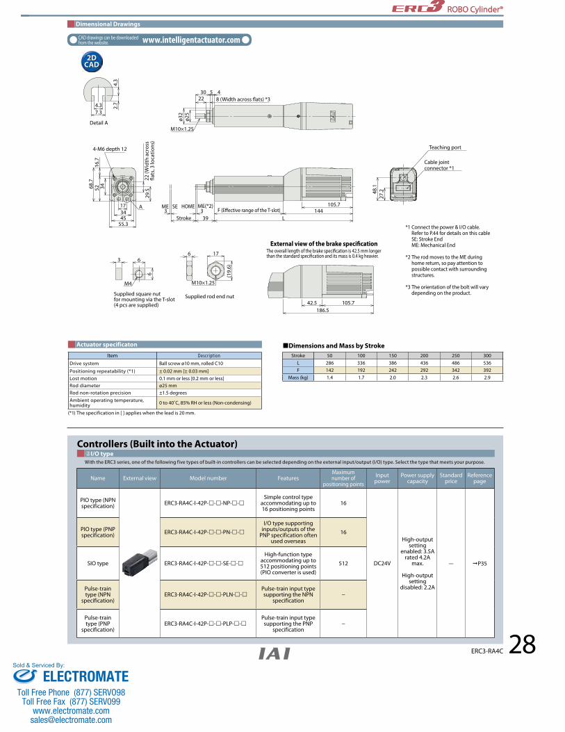
ROBO Cylinder® ROBO Cylinder®
Dimensional Drawings
CAD drawings can be downloaded from the website. www.intelligentactuator.com
2D CAD2D
CAD
28ERC3-RA4C
②I/O typeControllers (Built into the Actuator)
With the ERC3 series, one of the following five types of built-in controllers can be selected depending on the external input/output (I/O) type. Select the type that meets your purpose.
Name External view Model number FeaturesMaximum number of
positioning pointsInput power
Power supply capacity
Standard price
Reference page
PIO type (NPN specification) ERC3-RA4C-I-42P---NP--
Simple control type accommodating up to 16 positioning points
16
DC24V
High-output setting
enabled: 3.5A rated 4.2A
max.
High-output setting
disabled: 2.2A
— P35
PIO type (PNP specification) ERC3-RA4C-I-42P---PN--
I/O type supporting inputs/outputs of the
PNP specification often used overseas
16
SIO type ERC3-RA4C-I-42P---SE--High-function type
accommodating up to 512 positioning points (PIO converter is used)
512
Pulse-train type (NPN
specification)ERC3-RA4C-I-42P---PLN--
Pulse-train input type supporting the NPN
specification −
Pulse-train type (PNP
specification)ERC3-RA4C-I-42P---PLP--
Pulse-train input type supporting the PNP
specification −
Teaching port
Cable joint connector *1
*1 Connect the power & I/O cable. Refer to P.44 for details on this cable SE: Stroke End ME: Mechanical End
*2 The rod moves to the ME during home return, so pay attention to possible contact with surrounding structures.
*3 The orientation of the bolt will vary depending on the product.
27.248
.1
186.5105.742.5
17
(19.
6)
M10×1.25
Supplied rod end nut
66
6
M4
3
173445
55.3
345216
.7
29.5
68.7
A
4.37.3
2.7
4.3
ø25
ø32
453022
M10×1.25
3 339
144L
ME SE 105.7
External view of the brake speci�cationThe overall length of the brake speci�cation is 42.5 mm longer than the standard speci�cation and its mass is 0.4 kg heavier.
Stroke
ME(*2)HOMEF (E�ective range of the T-slot)
Supplied square nut for mounting via the T-slot(4 pcs are supplied)
4-M6 depth 1222
(Wid
th a
cros
s �a
ts, 3
loca
tions
)
Detail A
8 (Width across �ats) *3
Dimensions and Mass by StrokeActuator specificaton
(*1) The specification in [ ] applies when the lead is 20 mm.
Item Descr ipt ionDrive system Ball screw ø10 mm, rolled C10
Positioning repeatability (*1) ± 0.02 mm [± 0.03 mm]Lost motion 0.1 mm or less [0.2 mm or less]Rod diameter ø25 mmRod non-rotation precision ±1.5 degreesAmbient operating temperature, humidity 0 to 40˚C, 85% RH or less (Non-condensing)
Stroke 50 100 150 200 250 300L 286 336 386 436 486 536 F 142 192 242 292 342 392
Mass (kg) 1.4 1.7 2.0 2.3 2.6 2.9
ELECTROMATEToll Free Phone (877) SERVO98
Toll Free Fax (877) SERV099www.electromate.com
Sold & Serviced By:

ROBO Cylinder® ROBO Cylinder®
29 ERC3-RA6C
64
72
85
334.5~584.5
Stroke50~300
Unit: mm
③Cable length①Stroke
Paylo
ad (k
g)
Paylo
ad (k
g)
0102030405060
8070
0 100 200 300 400 500 700600Speed (mm/s)
0 100 200 300 400 500 700 900600 800Speed (mm/s)
0
5
10
15
20
25
30Lead 4Lead 4 Lead 4Lead 4
Lead 8Lead 8
Lead 8Lead 8Lead 16Lead 16
Lead 16Lead 16Lead 24Lead 24 Lead 24Lead 24
5555
1313 1515
22 2222
3333
88
17.517.5
2.52.533
HorizontalHorizontal VerticalVertical
The values below are based on operation at 0.3 G.The values below are based on operation at 0.3 G.
High-output setting enabled (Factory default)
Correlation diagrams of Speed and Payload With the ERC3 series, due to the characteristics of the pulse motor, payload decreases as the speed increases. Use the chart below to confirm that the desired speed and payload requirements are met.
Notes on selection
If the high-output setting is enabled (factory default), the duty must be limited. (Refer to P.13.) If the high-output setting is disabled, the payload and maximum speed become lower, but the actuator can be used at a duty of 100%. Refer to the operation manual for information on how to change the high-output setting. Refer to P.32 for the payload at each speed/acceleration when the high-output setting is enabled.Refer to P.33 for the specifications that apply when the high-output setting is disabled.
For other cautionary items, refer to “Explanations of/Cautionary Notes on Items Specified in Catalog (P.13).”
POINT
Legend ➀ Stroke ➁ I/O type ➂ Cable length ➃ Option
(Unit: mm/s) Leads and Payloads (Note 1) Take caution that the maximum payload decreases as the speed increases.
Actuator Specifications (High-output Setting Enabled)
Model number Lead(mm)
Maximum payload (Note 1) Maximum push force (N)
Stroke(mm)Horizontal (kg) Vertical (kg)
ERC3-RA6C-I-56P-24- ➀ - ➁ - ➂ - ➃ 24 13 3 182
50~300(every 50mm)
ERC3-RA6C-I-56P-16- ➀ - ➁ - ➂ - ➃ 16 40 8 273
ERC3-RA6C-I-56P-8- ➀ - ➁ - ➂ - ➃ 8 55 17.5 547
ERC3-RA6C-I-56P-4- ➀ - ➁ - ➂ - ➃ 4 70 25 1094
Stroke and Maximum SpeedStroke
Lead50~250
(every 50mm)300
(mm)
24 800 <600>
16 700 <560>
8 420 400
4 210 <175> 210 <175>
*Refer to P. 44 for maintenance cables.
Type Cable symbolStandard price
PIO type SIO type
Standard type (Robot cable)
P (1m) — —S (3m) — —M (5m) — —
Special length X06(6m)~X10(10m) — —
Stroke (mm) Standard price
50 —100 —150 —200 —250 —300 —
(*) If the simple absolute specification is selected, the separately sold PIO converter of simple absolute specification (with battery) is required.
Name Option code See page Standard priceBrake B P12 —Non-motor end specification NM P12 —
Simple absolute specification ABU P12 — (*)
Flange FL P12 —Foot bracket FT P12 —
④Options
The value inside < > indicates vertical usage.The values of lead 8 and lead 4 apply when acceleration is at 0.1G.
ERC3-RA6C ERC3
Series
RA6CType
56PMotor type Lead Stroke OptionCable lengthI/O type
56Pulse motorI: Incremental specification
NP: PIO (NPN) typePN: PIO (PNP) typeSE: SIO typePLN: Pulse-train (NPN) type PLP: Pulse-train (PNP) type
CN: CON typeMC: MEC type
24 : 24mm 16 : 16mm 8 : 8mm 4 : 4mm
Standard type Rod type Actuator Width 64mm
50:50mm
300:300mm(Can be set in 50mm
increments)
B : Brake NM : Non-motor end specification ABU: Simple absolute specificationFL : FlangeFT : Foot bracket
N: None P: 1mS: 3 m M: 5mX: Specified length
Controller type
IEncoder type
Model Specification Items
*Refer to P.11 for the description of items constituting the model number.
ELECTROMATEToll Free Phone (877) SERVO98
Toll Free Fax (877) SERV099www.electromate.com
Sold & Serviced By:

ROBO Cylinder® ROBO Cylinder®
30ERC3-RA6C
Dimensional Drawings
CAD drawings can be downloaded from the website. www.intelligentactuator.com
2D CAD2D
CAD
25506469
40
507213
85
A
6.510.5
3.6
8
10
10
M6
Supplied square nut for mounting via the T-slot(4 pcs are supplied)
5
22
(25.
4)
M14×1.5
Supplied rod end nut
8
33 176.5L49.5
ME(*2)ME SE SE
227.5134.551
134.5
4540.530.5
M14×1.5
Teaching port
Cable joint connector *1
*1 Connect the power & I/O cable. Refer to P.44 for details on this cable SE: Stroke End ME: Mechanical End
*2 The rod moves to the ME during home return, so pay attention to possible contact with surrounding structures.
*3 The orientation of the bolt will vary depending on the product.
44.965
.8
Detail A
10 (Width across �ats) (*3)
ø43
ø30
4-M8 depth 1627
(Wid
th a
cros
s �at
s, 3
loca
tions
)
Stroke F (E�ective range of the T-slot)
External view of the brake speci�cationThe overall length of the brake speci�cation is 51 mm longer than the standard speci�cation and its mass is 0.5 kg heavier.
②I/O typeControllers (Built into the Actuator)
With the ERC3 series, one of the following five types of built-in controllers can be selected depending on the external input/output (I/O) type. Select the type that meets your purpose.
Name External view Model number FeaturesMaximum number of
positioning pointsInput power
Power supply capacity
Standard price
Reference page
PIO type (NPN specification) ERC3-RA6C-I-56P---NP--
Simple control type accommodating up to 16 positioning points
16
DC24V
High-output setting
enabled: 3.5A rated 4.2A
max.
High-output setting
disabled: 2.2A
— P35
PIO type (PNP specification) ERC3-RA6C-I-56P---PN--
I/O type supporting inputs/outputs of the
PNP specification often used overseas
16
SIO type ERC3-RA6C-I-56P---SE--High-function type
accommodating up to 512 positioning points (PIO converter is used)
512
Pulse-train type (NPN
specification)ERC3-RA6C-I-56P---PLN--
Pulse-train input type supporting the NPN
specification −
Pulse-train type (PNP
specification)ERC3-RA6C-I-56P---PLP--
Pulse-train input type supporting the PNP
specification −
Dimensions and Mass by StrokeActuator specificaton
(*1) The specification in [ ] applies when the lead is 24 mm.
Item Descr ipt ionDrive system Ball screw ø12 mm, rolled C10
Positioning repeatability (*1) ± 0.02 mm [± 0.03 mm]Lost motion 0.1 mm or less [0.2 mm or less]Rod diameter ø30 mmRod non-rotation precision ±1.0 degreesAmbient operating temperature, humidity 0 to 40˚C, 85% RH or less (Non-condensing)
Stroke 50 100 150 200 250 300L 334.5 384.5 434.5 484.5 534.5 584.5 F 158 208 258 308 358 408
Mass (kg) 3.9 4.4 4.9 5.4 5.9 6.4
ELECTROMATEToll Free Phone (877) SERVO98
Toll Free Fax (877) SERV099www.electromate.com
Sold & Serviced By:

ROBO Cylinder® ROBO Cylinder®
31
In a push-motion operation, the push force can be used by changing the current-limiting value of the controller over a range of 20% to 70%. The maximum push-force varies depending on the model, so check the required push force from the table below and select an appropriate type meeting the purpose of use.
When performing a push-motion operation using a slider actuator, limit the push current so that the reactive force moment generated by the push force will not exceed 80% of the rated moment (Ma, Mb) specified in the catalog. To help with the moment calculations, the application position of the guide moment is shown in the figure below. Calculate the necessary moment by considering the offset of the push force application position. Note that if an excessive force exceeding the rated moment is applied, the guide may be damaged and the life may become shorter. Accordingly, include a sufficient safety factor when deciding on the push force.
Calculation example) If a push-motion operation is performed with an ERC3-SA7C by applying 100 N at the position shown to the right, the moment received by the guide, or Ma, is calculated as (46.5 + 50) x 100 = 9650 (N•mm) = 9.65 (N•m).
Since the rated moment Ma of the SA7C is 15 (N•m), 15 x 0.8 = 12 > 9.65, suggesting that this selection is acceptable. If an Mb moment generates due to the push-motion operation, calculate the moment from the overhang length and confirm, in the same way, that the calculated moment is within 80% of the rated moment.
ERC3 SA5C:h=36.5mm SA7C:h=46.5mmERC3CR/ERC3D SA5C:h=39mm SA7C:h=43mm
50m
mh
Selection Guideline (Correlation Diagram of the Push Force and the Current-limiting Value)
Correlation Diagrams of the Push Force and the Current-limiting Value The table below is only a reference, and the graphs may vary slightly from the actual values.
SA5C/RA4C type
RA6C type
SA7C type
0
50
350
400
300
250
200
150
100
Current-limiting value (%)
Push
forc
e (N
) Lead 3Lead 3
Lead 12Lead 12
Lead 6Lead 6
Lead 20Lead 20
70 806050403020100
0
200
1200
1000
800
600
400
70 806050403020100Current-limiting value (%)
Lead 4Lead 4
Lead 16Lead 16Lead 8Lead 8
Lead 24Lead 24
Push
forc
e (N
)
0
100
700
800
600
500
400
300
200
Current-limiting value (%)
Lead 4Lead 4
Lead 16Lead 16
Lead 8Lead 8
Lead 24Lead 24
70 806050403020100
Push
forc
e (N
)
The relationship of the push force and the current-limiting value is only a reference, and the graphs may vary slightly from the actual values.
If the current-limiting value is less than 20%, the push force may vary. Make sure the current-limiting value remains 20% or more.
The graphs assume a traveling speed of 20 mm/s during push-motion operation.
Notes on Use
ELECTROMATEToll Free Phone (877) SERVO98
Toll Free Fax (877) SERV099www.electromate.com
Sold & Serviced By:

ROBO Cylinder® ROBO Cylinder®
32
Selection Guideline (Table of ERC3 Payload by Speed/Acceleration)
The maximum acceleration/deceleration of the ERC3 is 1.0 G in a horizontal application or 0.5 G in vertical application. The payload drops as the acceleration increases, so when selecting a model, use the tables below to find one that meets the desired speed, acceleration and payload.
High-output setting enabled (Factory default)
ERC3-SA7CLead 16Lead 24 Lead 8 Lead 4Orientation Horizontal Vertical
Speed(mm/s)
Acceleration (G)0.1 0.3 0.5 0.7 1 0.1 0.3 0.5
0 35 35 35 26.5 26.5 7 6 4
140 35 35 35 26.5 26.5 7 6 4
280 35 28 28 22 18 7 6 4
420 30 23 12.5 11 10 5 5 4
560 22 15 9.5 7.5 5.5 5 4 3
700 20 11 5.5 3.5 2 3.5 2.5 1.5
840 4 2.5 1
980 2
Orientation Horizontal Vertical
Speed(mm/s)
Acceleration (G)0.1 0.3 0.5 0.7 1 0.1 0.3 0.5
0 43 40 40 40 40 15 14 13
70 43 40 40 40 40 15 14 13
140 40 40 40 38 35 15 14 13
210 40 36 35 30 24 11 9 9
280 40 23 11 8 2 8 7 6
350 35 4 2 2 5 3.5 1.5
420 25 2.5
490 15 1.5
Orientation Horizontal Vertical
Speed(mm/s)
Acceleration (G)0.1 0.3 0.5 0.7 1 0.1 0.3 0.5
0 45 45 45 40 35 22 22 22
35 45 45 45 40 35 22 22 22
70 45 42 42 35 35 22 22 22
105 42 40 40 35 35 20 20 19
140 42 40 25 25 22 15 12 11
175 38 18 10 4.5
210 35 6.5
Orientation Horizontal Vertical
Speed(mm/s)
Acceleration (G)0.1 0.3 0.5 0.7 1 0.1 0.3 0.5
0 20 17 15 13 11 3 3 3
200 20 17 15 13 11 3 3 3
400 20 14 14 13 10 3 3 3
600 20 14 10 8 8 3 3 3
800 10 10 8 6 2.5 3 2.5
1000 8 4 2 1 2
1200 4 2 1
ERC3-RA4CLead 12Lead 20 Lead 6 Lead 3Orientation Horizontal Vertical
Speed(mm/s)
Acceleration (G)0.1 0.3 0.5 0.7 1 0.1 0.3 0.5
0 25 25 14 14 12 4.5 4.5 3.5
100 25 25 14 14 12 4.5 4.5 3.5
200 25 25 11 8 8 4.5 4.5 3.5
300 25 25 11 7 5.5 4 4 3.5
400 17.5 16.5 8 4 3.5 3.5 3.5 2.5
500 15 5.5 2 2 3.5 2
600 10 3.5 2 1
700 6 2 1 1
Orientation Horizontal Vertical
Speed(mm/s)
Acceleration (G)0.1 0.3 0.5 0.7 1 0.1 0.3 0.5
0 6 6 6 5 4.5 1.5 1.5 1.5
160 6 6 6 5 4.5 1.5 1.5 1.5
320 6 6 6 5 3 1.5 1.5 1.5
480 6 6 6 4.5 3 1 1 1
640 6 4 3 2 1 1
800 4 3 0.5 0.5
Orientation Horizontal Vertical
Speed(mm/s)
Acceleration (G)0.1 0.3 0.5 0.7 1 0.1 0.3 0.5
0 40 40 31.5 30 25 12 12 10
50 40 40 31.5 30 25 12 12 10
100 40 40 31.5 24.5 21 12 12 10
150 40 40 24.5 17.5 17.5 11 11 7
200 40 40 21 14 12.5 8 8 5.5
250 35 24.5 17.5 14 11 7 7 4
300 28 21 12.5 12.5 8 5.5 5.5 4
350 24.5 17.5 9.5 5.5 5.5 4 3.5 3.5
400 17.5 9.5 7 4 2.5 3.5 2.5 2
450 17.5 5.5 2 1 1
Orientation Horizontal Vertical
Speed(mm/s)
Acceleration (G)0.1 0.3 0.5 0.7 1 0.1 0.3 0.5
0 40 40 40 40 35 18 18 17
25 40 40 40 40 35 18 18 17
50 40 40 40 40 35 18 18 17
75 40 40 40 40 35 16 16 16
100 40 40 40 40 35 16 15 15
125 40 40 40 40 30 16 12 10
150 40 40 40 30 25 10 8 5.5
175 36 36 35 25 20 10 5.5 5
200 36 28 28 19.5 14 7 5 4.5
225 36 16 14 10 6 4 3.5 2
Lead 20ERC3-SA5C
Lead 12 Lead 6 Lead 3Orientation Horizontal Vertical
Speed(mm/s)
Acceleration (G)0.1 0.3 0.5 0.7 1 0.1 0.3 0.5
0 6.5 6.5 5 5 4 1 1 1
160 6.5 6.5 5 5 4 1 1 1
320 6.5 6.5 5 5 4 1 1 1
480 6.5 6.5 4 4 4 1 1 1
640 6.5 6.5 3.5 3.5 3 1 1 1
800 5.5 5.5 3.5 3 1 1 1 1
960 5.5 2.5 2 1 0.5 0.5
1120 5.5 1 1 1 0.5 0.5
Orientation Horizontal Vertical
Speed(mm/s)
Acceleration (G)0.1 0.3 0.5 0.7 1 0.1 0.3 0.5
0 9 9 9 9 8 2.5 2.5 2.5
100 9 9 9 9 8 2.5 2.5 2.5
200 9 9 9 9 8 2.5 2.5 2.5
300 9 9 9 9 7 2.5 2.5 2.5
400 9 9 8 8 6 2.5 2.5 2.5
500 9 9 8 5.5 5.5 2.5 2.5 2
600 9 9 8 5.5 4 2.5 2 1.5
700 9 7 6 4 2.5 2.5 1 0.5
800 5.5 3.5 2 1 0.5 0.5
900 5 2.5 1 0.5
Orientation Horizontal Vertical
Speed(mm/s)
Acceleration (G)0.1 0.3 0.5 0.7 1 0.1 0.3 0.5
0 18 18 13 12 11 6 6 6
50 18 18 13 12 11 6 6 6
100 18 18 13 12 11 6 6 6
150 18 18 13 12 11 6 6 6
200 18 18 13 12 11 6 6 6
250 18 17 13 12 9 6 5 4.5
300 16 16 12 11 7 4.5 4 3.5
350 14 14 8 8 6 4 3.5 3
400 10.5 10 7 4.5 4 2.5 2 1.5
450 7.5 7 4 2.5 1 1 0.5
Orientation Horizontal Vertical
Speed(mm/s)
Acceleration (G)0.1 0.3 0.5 0.7 1 0.1 0.3 0.5
0 20 20 16 16 13 12 12 12
25 20 20 16 16 13 12 12 12
50 20 20 16 16 12 12 12 12
75 20 20 16 16 12 12 12 12
100 20 18 14 12 10 12 10.5 10.5
125 20 17 14 9.5 8 12 10.5 10.5
150 20 17 11 8 7 9.5 8 8
175 20 10 10 4.5 3.5 7 7 6
200 20 9 3 6 4 2
225 15 4.5
ERC3-RA6CLead 16Lead 24 Lead 8 Lead 4Orientation Horizontal Vertical
Speed(mm/s)
Acceleration (G)0.1 0.3 0.5 0.7 1 0.1 0.3 0.5
0 45 40 30 28 26 8 8 8
140 45 40 30 28 26 8 8 8
280 45 34 30 24 18 6.5 5.5 5.5
420 45 22 17 13 10 5.5 4 3
560 9.5 5 2.5 1.5 2 1
700 2
Orientation Horizontal Vertical
Speed(mm/s)
Acceleration (G)0.1 0.3 0.5 0.7 1 0.1 0.3 0.5
0 20 13 11 10 8 3 3 2
200 20 13 11 10 8 3 3 2
400 20 13 11 10 8 2 2 2
600 13 7 5 3.5 2 2
800 3 1
Orientation Horizontal Vertical
Speed(mm/s)
Acceleration (G)0.1 0.3 0.5 0.7 1 0.1 0.3 0.5
0 60 55 45 40 40 17.5 17.5 17.5
70 60 55 45 40 40 17.5 17.5 17.5
140 60 55 40 40 40 11 11 11
210 60 50 40 28 26 7.5 7.5 7
280 60 32 20 15 11 6 5.5 4.5
350 50 14 4.5 1 3 2.5 2
420 15 2
Orientation Horizontal Vertical
Speed(mm/s)
Acceleration (G)0.1 0.3 0.5 0.7 1 0.1 0.3 0.5
0 70 70 60 60 50 25 25 25
35 70 70 60 60 50 25 25 25
70 70 70 60 60 50 25 25 25
105 70 70 55 45 40 15 15 15
140 70 50 30 20 15 11.5 10 8
175 50 15 6 3
210 20
ELECTROMATEToll Free Phone (877) SERVO98
Toll Free Fax (877) SERV099www.electromate.com
Sold & Serviced By:

ROBO Cylinder® ROBO Cylinder®
33
Correlation diagrams of Speed and PayloadWith the ERC3 series, due to the characteristics of the pulse motor, payload decreases as the speed increases.Use the chart below to confirm that the desired speed and payload requirements are met.
The values below are based on operation at 0.2 Gfor lead 4 and 0.3 G for all other leads.
The values below are based on operation at 0.2 Gfor lead 3 and 0.3 G for all other leads.
0 100 200 300 400 500 700 900600 8000
Speed (mm/s)
2468
1012
20181614
0 100 200 300 400 500 700 900600 8000
Speed (mm/s)
51015202530
454035
0 100 200 300 400 500 7006000
Speed (mm/s)
5
10
15
20
25
30
0 100 200 300 400 500 700 900600 8000
Speed (mm/s)
102030405060
8070
ERC3-RA4C ERC3-RA6C
23.5
17.5
The values below are based on operation at 0.2 G.The values below are based on operation at 0.2 G.
The values below are based on operation at 0.2 Gfor lead 4 and 0.3 G for all other leads.
The values below are based on operation at 0.2 Gfor lead 3 and 0.3 G for all other leads.
00 200 400
Speed (mm/s)600 800 1000 1200 1400
200 400 600 800 1000 1200 14000
5
10
15
20
25
0
Speed (mm/s)
2
4
6
8
10
12
14
0 200 400 600 800 1000 1200 14000
Speed (mm/s)
5
10
15
0 200 400 600 800 1000 1200 14000
Speed (mm/s)
5
10
15
20
25
ERC3�-SA5C ERC3�-SA7C
The values below are based on operation at 0.2 G.The values below are based on operation at 0.2 G.
Paylo
ad (k
g)
Paylo
ad (k
g)
Paylo
ad (k
g)Pa
yload
(kg)
Paylo
ad (k
g)Pa
yload
(kg)
Paylo
ad (k
g)
Paylo
ad (k
g)
HorizontalHorizontal
HorizontalHorizontalHorizontalHorizontal
HorizontalHorizontal
2222
22
33
0.50.5
0.50.5 0.50.5 0.50.533 22 11
2525
5555
2525
0.50.5
1.51.5
0.50.5 0.50.5 0.50.5
2.52.5
2.52.5
2.52.5
4.54.5
2.52.51.51.5
1.51.5
1111 3.53.53.53.5
66
1212
66
Lead 4Lead 4
Lead 4Lead 4
Lead 4Lead 4
Lead 4Lead 4
Lead 20Lead 20
Lead 20Lead 20
Lead 20Lead 20
Lead 20Lead 20
Lead 12Lead 12
Lead 12Lead 12
Lead 12Lead 12
Lead 12Lead 12
Lead 6Lead 6
Lead 6Lead 6
Lead 6Lead 6
Lead 6Lead 6
Lead 3Lead 3
Lead 3Lead 3
Lead 3Lead 3
Lead 3Lead 3
Lead 8Lead 8
Lead 8Lead 8
Lead 8Lead 8
Lead 8Lead 8
Lead 16Lead 16
Lead 16Lead 16
Lead 16Lead 16
Lead 16Lead 16
Lead 24Lead 24
Lead 24Lead 24
Lead 24Lead 24
Lead 24Lead 24
1111
12121212
66
VerticalVertical VerticalVertical
VerticalVertical VerticalVertical
High-output setting disabled Specification
ELECTROMATEToll Free Phone (877) SERVO98
Toll Free Fax (877) SERV099www.electromate.com
Sold & Serviced By:
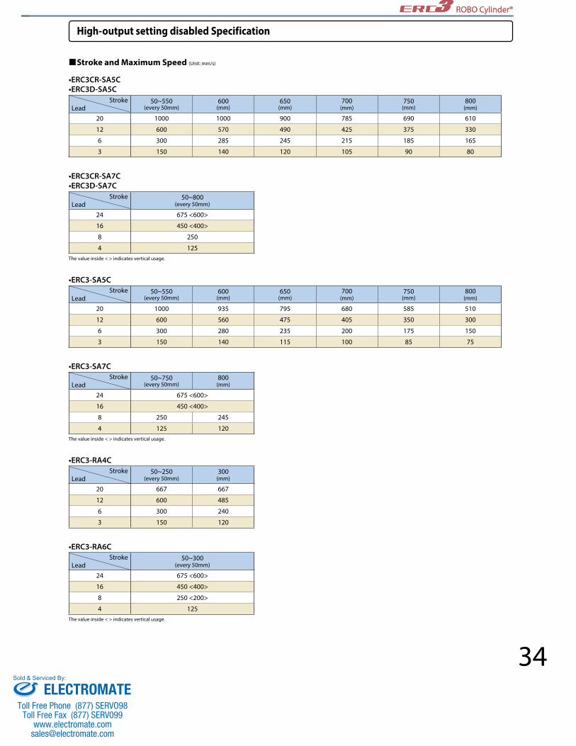
ROBO Cylinder® ROBO Cylinder®
34
High-output setting disabled Specification
Stroke and Maximum Speed (Unit: mm/s)
•ERC3CR-SA5C•ERC3D-SA5C
•ERC3-SA5C
•ERC3-RA4C
•ERC3CR-SA7C•ERC3D-SA7C
•ERC3-SA7C
•ERC3-RA6C
StrokeLead
50~550(every 50mm)
600(mm)
650(mm)
700(mm)
750(mm)
800(mm)
20 1000 1000 900 785 690 610
12 600 570 490 425 375 330
6 300 285 245 215 185 165
3 150 140 120 105 90 80
StrokeLead
50~550(every 50mm)
600(mm)
650(mm)
700(mm)
750(mm)
800(mm)
20 1000 935 795 680 585 510
12 600 560 475 405 350 300
6 300 280 235 200 175 150
3 150 140 115 100 85 75
StrokeLead
50~250(every 50mm)
300(mm)
20 667 667
12 600 485
6 300 240
3 150 120
StrokeLead
50~300(every 50mm)
24 675 <600>
16 450 <400>
8 250 <200>
4 125
StrokeLead
50~800(every 50mm)
24 675 <600>
16 450 <400>
8 250
4 125
StrokeLead
50~750(every 50mm)
800(mm)
24 675 <600>
16 450 <400>
8 250 245
4 125 120
The value inside < > indicates vertical usage.
The value inside < > indicates vertical usage.
The value inside < > indicates vertical usage.
ELECTROMATEToll Free Phone (877) SERVO98
Toll Free Fax (877) SERV099www.electromate.com
Sold & Serviced By:

ROBO Cylinder® ROBO Cylinder®
35 ERC3
Model number NP/PN/SE/PLN/PLP
Controller part of actuator with built-in controller
ERC3 controller specification
Model number
List of Models
➆&➈refers to the I/O type and controller type shown in the above table.
Controller type CON type MEC type
Operation mode Positioner mode Pulse-train control mode Positioner mode
I/O typePIO
SIO NPN PNPPIO
SIONPN PNP NPN PNP
Type(I/O type) NP PN SE PLN PLP NP PN SE
Position points 16 points
512 points (When the PIO converter or gateway unit is used)
— — 3 points 2 points/3 points
Description Basic type Basic type The PIO converter or
gateway unit can be used. (Note)
When pulse trains are
used
When pulse trains are
used3-point
movement 3-point
movement
The Quick Teach and PIO converter
or gateway unit can be used. (Note)
External view
Standard price —
20 for SA5C/RA4C 20 mm
12 for SA5C/RA4C 12 mm
6 for SA5C/RA4C 6 mm
3 for SA5C/RA4C 3 mm
24 for SA7C/RA6C 24 mm
16 for SA7C/RA6C 16 mm
8 for SA7C/RA6C 8 mm
4 for SA7C/RA6C 4 mm
Series Type Motor type Stroke Controller type OptionLead I/OType Cable lengthI
Encoder type
N None
P 1m
S 3m
M 5m
X Specified length
NP PIO (NPN) type
PN PIO (PNP) type
SE SIO type
PLN Pulse-train (NPN) type
PLP Pulse-train (PNP) type
CN CON type
MC MEC type
(Can be set in 50mm increments)
* If the I/O type is PLN or PLP, "CN" is selected automatically.
* The simple absolute specification can be selected only when the I/O type is "SIO communication." * The flange and foot bracket option can be selected only for rod types.
* The standard cable is a robot cable.
ERC3 Standard type
ERC3CR Cleanroom type
ERC3D Simple, dustproof type
42P Pulse motor 42size
56P Pulse motor 56size
I Incremental type
➀ ➁ ➃ ➅ ➈ ➉➄ ➆ ➇➂
Slider type
50 50 mm
800 800 mm
Rod type
50 50 mm
300 300 mm B Brake
NM Non-motor end specification
ABU Simple absolute specification
FL Flange FT Foot bracket
VR Vacuum joint on opposite side
SA5C Actuator width 50 mm
SA7C Actuator width 74 mm
RA4C Actuator width 45 mm
RA6C Actuator width 64 mm
(Note) The PIO converter and gateway unit cannot be used at the same time.
ELECTROMATEToll Free Phone (877) SERVO98
Toll Free Fax (877) SERV099www.electromate.com
Sold & Serviced By:

ROBO Cylinder® ROBO Cylinder®
36ERC3
PC Wiring Diagram
System Configuration
SIO connector
(Only one can be connected) Teaching pendantPC
ERC3
The SIO connector is used to connect a teaching tool.
PIO Type/Pulse-train type
ERC3
PLC
ERC3
PIO Converter
PLC
SIO Type
Teaching pendant(See P51~54.)<Model number: CON-PTA ><Model number: SEP-PT><Model number: RCM-PST>
Teaching pendant(See P51~54.)<Model number: CON-PTA ><Model number: SEP-PT><Model number: RCM-PST>I/O flat cable
<Model number: CB-PAC-PIO>Standard lengths: 2 m/3 m/5 mRefer to P. 47 for the maintenance cable.
Power & I/O cable for SIO type <Model CB-ERC3S-PWBIO>Standard lengths: 1 m/3 m/5 mRefer to P. 44 for the maintenance cable.
Power & I/O cable for PIO type <Model number: CB-ERC3P-PWBIO>Standard lengths: 1 m/3 m/5 mRefer to P. 44 for the maintenance cable.
PC software (See P54) PC software for ROBO Cylinder® * The cable is supplied with the PC software. (RS 232 connection version) <Model number: RCM-101-MW> (USB connection version) <Model number: RCM-101-USB> MEC PC software * A separate cable is required.
PC software (See P54) PC software for ROBO Cylinder® * The cable is supplied with the PC software. (RS 232 connection version) <Model number: RCM-101-MW> (USB connection version) <Model number: RCM-101-USB> MEC PC software * A separate cable is required.
24-VDC power supply <Model number: PS-241 (100-V input)><Model number: PS-242 (200-V input)>
24-VDC power supply <Model number: PS-241 (100-V input)><Model number: PS-242 (200-V input)>
Simple absolute battery (absolute specification)
* If the pulse-train type is used with a PLC of open collector output, the AK-04 is required.
Supplied with Actuator
Supplied with Actuator
Supplied with PIO converter
Supplied with PIO converter
Option
Option
Option
Download
Option
Option
Option
Option
ELECTROMATEToll Free Phone (877) SERVO98
Toll Free Fax (877) SERV099www.electromate.com
Sold & Serviced By:

Item Description
Power supply voltage 24 VDC±10%
Load current (including current consumed for control) High-output setting enabled: 3.5 A rated/4.2 A max. High-output setting disabled: 2.2A
Heat output High-output setting enabled: 8 W High-output setting disabled: 5W
Rush current (Note 1) 8.3A
Momentary power failure resistance MAX. 500μs
Motor control method Field-weakening vector control
Supported encoder Incremental encoder of 800 pulses/rev in resolution
Actuator cable length 10 m max.
Serial communication interface (SIO port) RS485: 1 channel (conforming to Modbus protocol RTU/ASCII) / Speed: 9.6 to 230.4 kbpsActuators can be controlled via serial communication in a mode other than pulse-train
External interface PIO specification Dedicated 24-VDC signal input/output (NPN or PNP selected)—Up to 6 input points, up to 4 output points Cable length: 10m max.
Data setting/input method PC software, touch-panel teaching pendant, quick teach
Data retention memory Position data and parameters are saved in the non-volatile memory (There is no limit to the number of times the memory can be written.)
Operation mode Positioner mode/Pulse-train control mode
Number of positions in positioner mode Standard 8 points, maximum 16 points Note) Positioning points vary depending on the selected PIO pattern.
Pulse-train interface
Input pulse
Differential method (line driver method): 200 kpps max. / Cable length: 10m max.
Open collector method: Not supported* If the host is of open collector output type, use the optional AK-04 (sold separately) to convert open collector pulses to differential pulses.
Command pulse magnification (electronic gear ratio: A/B)
1/50 < A/B < 50/1Setting range of A and B (set by parameters): 1 to 4096
Feedback pulse output None
LED indicators (installed on the motor unit) Servo ON (green), servo OFF (unlit), emergency stop (red), alarm (red), resetting (orange)
Isolation resistance 500 VDC, 10 MΩ or more
Electric shock protection mechanism Class I basic isolation
Cooling method Natural air cooling
Environment
Ambient operating temperature 0 to 40°C
Ambient operating humidity 85%RH or less (non-condensing)
Ambient storage temperature -20 to 70°C (excluding batteries)
Operating altitude Altitude 1000m or less
Protection degree IP20
Cooling method Natural air cooling
Vibration resistance Number of vibrations: 10 to 57 Hz/Amplitude: 0.075 mm (Test conditions) Number of vibrations: 57 to 150 Hz/Acceleration: 9.8 m/s2
Sweep time in X/Y/Z directions: 10 minutes/Number of sweeps: 10 times
Impact (Test conditions) 150mm/sec2, 11mm/sec, sinusoidal half pulse, 3 times each in X, Y and Z directions
37 ERC3
ROBO Cylinder®
List of Base Controller Specifications
Note 1 Rush current will flow for approx. 5msec after the power is turned on (at 40°C). Take note that the value of rush current varies depending on the impedance of the power line.
The ERC3 series has no built-in emergency stop circuit, so the customer must provide an emergency stop circuit. Refer to the operation manual for details on the emergency stop circuit.
Emergency Stop Circuit
ELECTROMATEToll Free Phone (877) SERVO98
Toll Free Fax (877) SERV099www.electromate.com
Sold & Serviced By:

Pin number
Category
Controller type CN (CON type) MC (MEC type)
PIO function
Parameter No. 25 (PIO pattern) selection Selected on teaching pendantor in PC software0 1 2
8-point type Solenoid type 16-point type Standard/Movement between 2 points (single solenoid)
2 inputs/Movement among 3 points
Input
Number of positioning points 8 points 3 points 16 points 2 points 3 pointsHome return signal × × × ×
Jog signal × × × × ×Teaching signal (writing
of current position) × × × × ×
Brake release × × × × ×
OutputMoving signal × × × × ×
Zone signal × × ×Position zone signal × × × ×
A1 Frame ground FGB1 +24V for control power supply CPA2 − —B2 0 V for control power supply GNDA3 External brake release input BKB3 +24V for motor power supply MPA4 Emergency stop input EMGB4 0 V for motor power supply GNDA5 − —B5 − —A6 − —B6 − —A7 − —B7 − —A8 − —B8 − —A9
Input
IN0 PC1 ST0 PC1 ST0 ST0B9 IN1 PC2 ST1 PC2 — ST1
A10 IN2 PC4 ST2 PC4 RES RESB10 IN3 HOME — PC8 — —A11 IN4 CSTR RES CSTR — —B11 IN5 *STP *STP *STP — —A12
Output
OUT0 PEND PE0 PEND LS0/PE0 LS0/PE0B12 OUT1 HEND PE1 HEND LS1/PE1 LS1/PE1A13 OUT2 ZONE1 PE2 PZONE/ZONE1 HEND LS2/PE2B13 OUT3 *ALM *ALM *ALM *ALM *ALM
* The output circuit is not isolated from signals output to external equipment.* The input circuit is not isolated from signals input from external equipment.
NPN specification NPN specification
PNP specification PNP specification
Item SpecificationInput points 6 pointsInput voltage 24 VDC ±10%Input current 5mA/1 circuitLeak current 1mA/point max.
Item SpecificationOutput points 4 pointsLoad voltage 24 VDC ±10%Maximum load current 5mA/1 circuitResidual voltage 2 V or less
ERC3Internal power supply: 24 V
5.6KΩ100KΩ
20KΩInput
terminal
Internal circuit
External power supply: 24 V
15ΩLoad
Output terminal
ERC3
Internal circuit
ERC3
5.6KΩ
100KΩ
20KΩInput
terminal
Internal circuit
External power supply: 24 V
Internal power supply: 24 V
15ΩLoad
Output terminal
ERC3
Internal circuit
38ERC3
ROBO Cylinder®
Positioner modeI/O specification (PIO type)
I/O Signal Table (PIO Type) [ERC3 and PLC Connected Directly]
Input Part Output Part
(Note) Signals marked with an asterisk (*) (ALM/STP) are negative logic signals so they are nomally on.
ELECTROMATEToll Free Phone (877) SERVO98
Toll Free Fax (877) SERV099www.electromate.com
Sold & Serviced By:
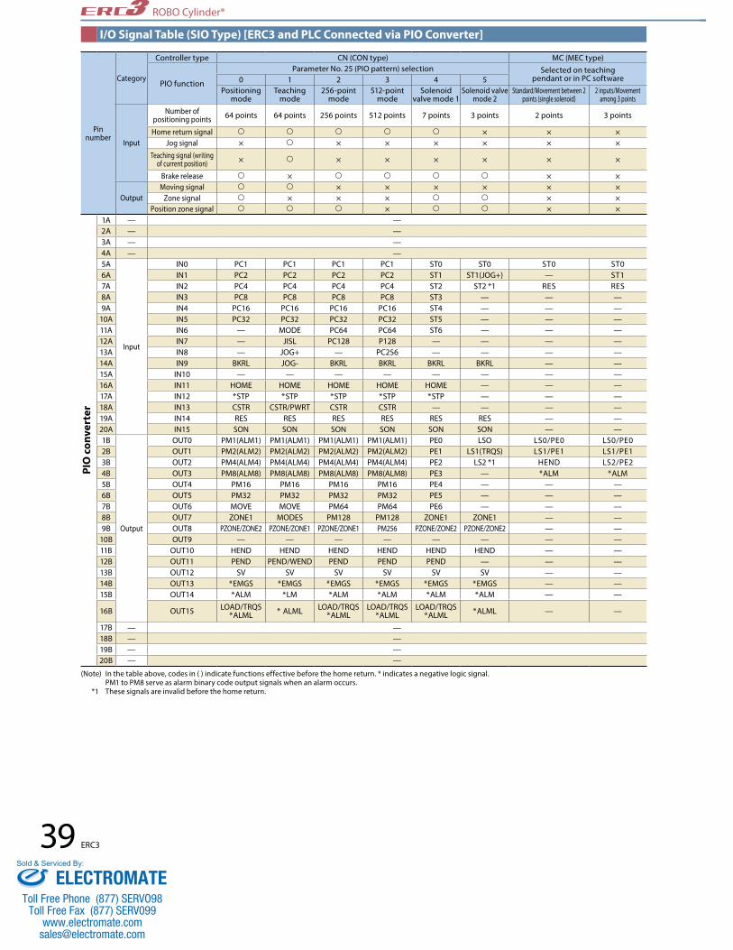
Pin number
Category
Controller type CN (CON type) MC (MEC type)
PIO function
Parameter No. 25 (PIO pattern) selection Selected on teaching pendant or in PC software0 1 2 3 4 5
Positioning mode
Teaching mode
256-point mode
512-point mode
Solenoid valve mode 1
Solenoid valve mode 2
Standard/Movement between 2 points (single solenoid)
2 inputs/Movement among 3 points
Input
Number of positioning points 64 points 64 points 256 points 512 points 7 points 3 points 2 points 3 points
Home return signal × × ×Jog signal × × × × × × ×
Teaching signal (writing of current position) × × × × × × ×
Brake release × × ×
OutputMoving signal × × × × × ×
Zone signal × × × × ×Position zone signal × × ×
1A — —2A — —3A — —4A — —5A
Input
IN0 PC1 PC1 PC1 PC1 ST0 ST0 ST0 ST06A IN1 PC2 PC2 PC2 PC2 ST1 ST1(JOG+) — ST17A IN2 PC4 PC4 PC4 PC4 ST2 ST2 *1 RES RES8A IN3 PC8 PC8 PC8 PC8 ST3 — — —9A IN4 PC16 PC16 PC16 PC16 ST4 — — —
10A IN5 PC32 PC32 PC32 PC32 ST5 — — —11A IN6 — MODE PC64 PC64 ST6 — — —12A IN7 — JISL PC128 P128 — — — —13A IN8 — JOG+ — PC256 — — — —14A IN9 BKRL JOG- BKRL BKRL BKRL BKRL — —15A IN10 — — — — — — — —16A IN11 HOME HOME HOME HOME HOME — — —17A IN12 *STP *STP *STP *STP *STP — — —18A IN13 CSTR CSTR/PWRT CSTR CSTR — — — —19A IN14 RES RES RES RES RES RES — —20A IN15 SON SON SON SON SON SON — —1B
Output
OUT0 PM1(ALM1) PM1(ALM1) PM1(ALM1) PM1(ALM1) PE0 LSO LS0/PE0 LS0/PE02B OUT1 PM2(ALM2) PM2(ALM2) PM2(ALM2) PM2(ALM2) PE1 LS1(TRQS) LS1/PE1 LS1/PE13B OUT2 PM4(ALM4) PM4(ALM4) PM4(ALM4) PM4(ALM4) PE2 LS2 *1 HEND LS2/PE24B OUT3 PM8(ALM8) PM8(ALM8) PM8(ALM8) PM8(ALM8) PE3 — *ALM *ALM5B OUT4 PM16 PM16 PM16 PM16 PE4 — — —6B OUT5 PM32 PM32 PM32 PM32 PE5 — — —7B OUT6 MOVE MOVE PM64 PM64 PE6 — — —8B OUT7 ZONE1 MODES PM128 PM128 ZONE1 ZONE1 — —9B OUT8 PZONE/ZONE2 PZONE/ZONE1 PZONE/ZONE1 PM256 PZONE/ZONE2 PZONE/ZONE2 — —
10B OUT9 — — — — — — — —11B OUT10 HEND HEND HEND HEND HEND HEND — —12B OUT11 PEND PEND/WEND PEND PEND PEND — — —13B OUT12 SV SV SV SV SV SV — —14B OUT13 *EMGS *EMGS *EMGS *EMGS *EMGS *EMGS — —15B OUT14 *ALM *LM *ALM *ALM *ALM *ALM — —
16B OUT15 LOAD/TRQS*ALML * ALML LOAD/TRQS
*ALMLLOAD/TRQS
*ALMLLOAD/TRQS
*ALML *ALML — —
17B — —18B — —19B — —20B — —
PIO
con
vert
er
39 ERC3
ROBO Cylinder®
(Note) In the table above, codes in ( ) indicate functions effective before the home return. * indicates a negative logic signal. PM1 to PM8 serve as alarm binary code output signals when an alarm occurs. *1 These signals are invalid before the home return.
I/O Signal Table (SIO Type) [ERC3 and PLC Connected via PIO Converter]
ELECTROMATEToll Free Phone (877) SERVO98
Toll Free Fax (877) SERV099www.electromate.com
Sold & Serviced By:

Category Signal name Signal abbreviation Function overview
Input
PTP strobe (start signal) CSTR The actuator starts moving to the position set by the command position number.
Command position number PC1~PC256 This signal is used to input the position number of the position to move the actuator to (binary input).
Forced brake release BKRL The brake is forcibly released.
Pause *STP When this signal turns OFF while the actuator is moving, the actuator will decelerate to a stop. The remaining travel is put on hold while the actuator is stopped and will resume when the signal turns ON.
Reset RES Present alarms are reset when this signal turns ON. By turning ON this signal while the actuator is paused (*STP signal is OFF), the remaining travel can be cancelled.
Servo ON SON The servo is ON while this signal is ON, and OFF while the signal is OFF.
Home return HOME Home return operation is performed when this signal is turned ON.
Teaching mode MODE The actuator switches to the teaching mode when this signal turns ON. The mode will not change unless the CSTR, JOG+ and JOG- signals are all OFF and the actuator is not operating.
Jog/inching switching JISL The actuator can be jogged with a JOG+ or JOG- command while this signal is OFF. The actuator operates by inching with a JOG+ or JOG- command while this signal is ON.
Jog JOG +JOG −
When the JISL signal is OFF, the actuator jogs in the positive direction upon detection of the ON edge of the JOG+ signal, or in the negative direction upon detection of the ON edge of the JOG- signal. The actuator decelerates to a stop if the OFF edge is detected while jogging in each direction. The actuator operates by inching when the JISL signal is ON.
Current position write PWRT When a position number is specified and this signal is turned ON for 20 ms or more in the teaching mode, the current position is written to the specified position number.
Start signal ST0~ST6 In the solenoid mode, the actuator moves to the specified position when this signal turns ON.
Output
Positioning complete PEND/INPThis signal turns ON when the actuator reaches the positioning band after moving. The PEND signal does not turn OFF even when the actuator moves beyond the positioning band, but the INP signal turns OFF. A parameter is used to switch between PEND and INP.
Completed position number PM1~PM256 The position number of the position reached upon completion of positioning is output (by a binary signal).
Home return complete HEND This signal turns ON upon completion of home return. It will remain ON until the home position is lost.
Zone signal 1 ZONE1This signal turns ON when the current position of the actuator falls within the parameter-set range.
Zone signal 2 ZONE2
Position zone PZONE This signal turns ON when the current position of the actuator enters the range set in the position data table while moving to a position. This signal can be used with ZONE1, but the PZONE signal is effective only when moving to a set position.
Alarm *ALM This signal remains ON while the controller is normal, and turns OFF when an alarm occurs.
Moving MOVE This signal is ON while the actuator is moving (also during home return and push-motion operation).
Servo ON SV This signal is ON when the servo is ON.
Emergency stop output *EMGS This signal is ON when the controller is not in the emergency stop mode, and turns OFF when an emergency stop is actuated.
Teaching mode output MODES This signal turns ON when the actuator enters the teaching mode due to an input of the MODE signal. It turns OFF when the actuator returns to the normal mode.
Write complete WENDThis signal is OFF immediately after switching to the teaching mode, and turns ON the moment the writing per the PWRT signal is completed.This signal also turns OFF when the PWRT signal turns OFF.
Current position number PE0~PE6 This signal turns ON when the actuator completes moving to the target position in the solenoid mode.
Limit switch output LS0~LS2 This signal turns ON when the current position of the actuator enters the positioning band (±) around the target position. If the home return has been completed, this signal is output even before a move command is issued or the servo is OFF.
Load output judgment status LOAD This signal turns ON when the in-certification-range command torque exceeds the threshold.
Torque level status signal TRQS This signal turns ON when the motor current reaches the threshold.
Minor failure alarm *ALML This signal is output when a message-level alarm generates.
40ERC3
ROBO Cylinder®
Explanation of Signal Names
(Note) In the table above, * indicates a negative logic signal.
ELECTROMATEToll Free Phone (877) SERVO98
Toll Free Fax (877) SERV099www.electromate.com
Sold & Serviced By:

ERC3
(Not used)Serial communication
GroundCN2
FG
1A SGA
1B SGB
Orange (red 1)
Orange (black 1)
PIO connecter
0V (NPN specification)24-VDC (PNP specification)
24-VDC (NPN specification)0V (PNP specification)
*The wire colors change as follows if a robot cable is used.
(Note) To forcibly release the brake, provide a switch between BKR and 0V and turn it ON.
I/O interface (Refer to the I/O connection for each PIO pattern on P. 38.)
A9
A10
A11
A12
A13
B13
B12
B11
B10
B9
Line color Pin numberGray (red 1) 2AGray (black 1) 2BGray (red 2) 7AGray (black 2) 7B
Input to host system(PLC)Output from
host system(PLC)
PIO connecterPIO converter
I/O interface (Refer to the I/O connection for each PIO pattern on P. 39.)
1A2A3A4A5A6A7A8A9A10A11A12A13A14A15A16A17A18A19A20A
1B2B3B4B5B6B7B8B9B10B11B12B13B14B15B16B17B18B19B20B
Brown-1Red-1Orange-1Yellow-1Green-1Blue-1Purple-1Gray-1White-1Black-1Brown-2Red-2Orange-2Yellow-2Green-2Blue-2Purple-2Gray-2White-2Black-2
Brown-1Red-1Orange-1Yellow-1Green-1Blue-1Purple-1Gray-1White-1Black-1Brown-2Red-2Orange-2Yellow-2Green-2Blue-2Purple-2Gray-2White-2Black-2
0V (NPN specification)24-VDC (PNP specification)
Output from host system
(PLC)
Input to host system(PLC)
24-VDC (NPN specification)0V (PNP specification)
41 ERC3
ROBO Cylinder®
I/O Wiring Diagram
PIO 8-point Type (ERC3 and PLC Connected Directly)
PIO Positioning Mode (Standard Type) (ERC3 and PLC Connected via PIO Converter)
ELECTROMATEToll Free Phone (877) SERVO98
Toll Free Fax (877) SERV099www.electromate.com
Sold & Serviced By:

Code RemarksDifferential input voltage range 26C31 or equivalent
Maximum cable length Differential line driver method: 10m max. Open collector method (AK-04 used): 2m max.
Maximum number of input pulses Differential line driver method: 200 kpps max. Open collector method (AK-04 used): 60kpps max.
ERC3
Internal circuit
Internal circuit
18KΩ
26C31 or equivalent line driver
26C31 or equivalent line driver
PP
/PP
/NP
NP
180Ω
1KΩ
1KΩ
ERC3Host unit
CB-ERC3P-PWBIO
Positioning unit Pulse-train control
Pulse command (corresponding to line driver 26C31)
B7 PP
/ PP
NP
/ NP
B8
A8
A7
ERC3Host unit
0V
0V
Pulse signal
CB-ERC3P-PWBIO
Positioning unitPulse converter
AK-04(Optional)
Pulse-train control
B7
B8
PP
/ PP
PP
/ PP
24V
GND
PP
NP
1
2
1
2
3
4
3
4NP
/ NP
NP
/ NP
A7
A8
+24V0V
42ERC3
ROBO Cylinder®
Pulse-train control modeI/O specification (Pulse-train type)
Pulse-train Control Circuit
Input Part
* If the user-side I/O is of open collector type, use the AK-04.
Host Unit = Differential Type
Host Unit = Open Collector Type
* The AK-04 (optional) is needed to input pulses. * Use the same power supply for open collector input/output to/from the host and for the AK-04.
ELECTROMATEToll Free Phone (877) SERVO98
Toll Free Fax (877) SERV099www.electromate.com
Sold & Serviced By:

Pin number Category I/O number Signal abbreviation Signal name Description of function A1 Frame ground FG — Frame ground. B1 +24 V for control power supply CP — +24 V of the control power supply is input.A2 —B2 0 V for control power supply GND — 0 V of the control power supply.A3 External brake release input BK — This signal is used to release the brake externally. The brake is released when +24 V is input.B3 +24 V for motor power supply MP — +24 V of the motor power supply is input.A4 Emergency stop input EMG — Input signal for emergency stop.B4 0 V for motor power supply GND — +24 V of the motor power supply is input.A5B5A6B6A7 /PP Command pulseB7 PP Command pulseA8 /NP Command pulseB8 NP Command pulseA9
Input
IN0 SON Servo ON The servo is ON while this signal is ON, and OFF while the signal is OFF.B9 IN1 TL Torque limit selection When this signal is turned ON, the motor torque is limited to the value set by a parameter.
A10 IN2 HOME Home return Home return operation is performed when this signal is turned ON.
B10 IN3RES Reset This signal serves as a reset signal when the torque is not limited (torque TL signal is OFF).
When this signal turns ON, present alarms are reset.
DCLR Deviation counter clear
This signal serves as a deviation counter signal when the torque is limited (torque TL signal is ON). This signal clears the deviation counter.
A11 IN4 —B11 IN5 —A12
Output
OUT0 SV Servo ON status This signal turns ON when the servo is ON.
B12 OUT1INP Positioning
completeThis signal serves as a positioning complete signal when the torque is not limited (torque TL signal is OFF). It turns ON when the remaining travel pulses in the deviation counter are within the range of positioning band.
TLR Torque limited This signal serves as a torque limited signal when the torque is limited (torque TL signal is ON). If the torque is limited, this signal turns ON when the torque limit is reached.
A13 OUT2 HEND Home return complete This signal turns ON upon completion of home return.B13 OUT3 *ALM Controller alarm status This signal turns ON when the controller is normal, and turns OFF when an alarm generates.
Pin number Category I/O number Signal abbreviation Signal name Description of function A1 Frame ground FG — Frame ground.B1 +24 V for control power supply CP — +24 V of the control power supply is input.A2 —B2 0 V for control power supply GND — 0 V of the control power supply.
A3 External brake release input BK — This signal is used to release the brake externally. The brake is released when +24 V is input.
B3 +24 V for motor power supply MP — +24 V of the motor power supply is input. A4 Emergency stop input EMG — Input signal for emergency stop.B4 0 V for motor power supply GND — +24 V of the motor power supply is input.A5B5A6B6A7 /PP Command pulseB7 PP Command pulseA8 /NP Command pulseB8 NP Command pulseA9
Input
IN0 SON Servo ON The servo is ON while this signal is ON, and OFF while the signal is OFF.B9 IN1 TL Torque limit selection When this signal is turned ON, the motor torque is limited to the value set by a parameter.
A10 IN2 HOME Home return Home return operation is performed when this signal is turned ON.B10 IN3 RES Reset Present alarms are reset when this signal is turned ON.A11 IN4 —B11 IN5 —A12
Output
OUT0 SV Servo ON status This signal turns ON when the servo is ON.B12 OUT1 INP Positioning complete This signal turns ON when the amount of remaining travel pulses in the deviation counter falls within the positioning band.A13 OUT2 HEND Home return complete This signal turns ON upon completion of home return.B13 OUT3 *ALM Controller alarm status This signal turns ON when the controller is normal, and turns OFF when an alarm generates.
43 ERC3
ROBO Cylinder®
I/O Signals for the Pulse-train Control Mode
[2] Push-motion Operation - PIO Pattern: 1
*indicates a negative logic signal. Negative logic signals are normally ON while the power is supplied, and turn OFF when the signal is output.
[1] Positioning Operation - PIO Pattern: 0
* indicates a negative logic signal. Negative logic signals are normally ON while the power is supplied, and turn OFF when the signal is output.
The table below lists the signal assignments for the flat cable for the pulse-train control mode. Connect an external device (such as PLC) according to this table.
ELECTROMATEToll Free Phone (877) SERVO98
Toll Free Fax (877) SERV099www.electromate.com
Sold & Serviced By:
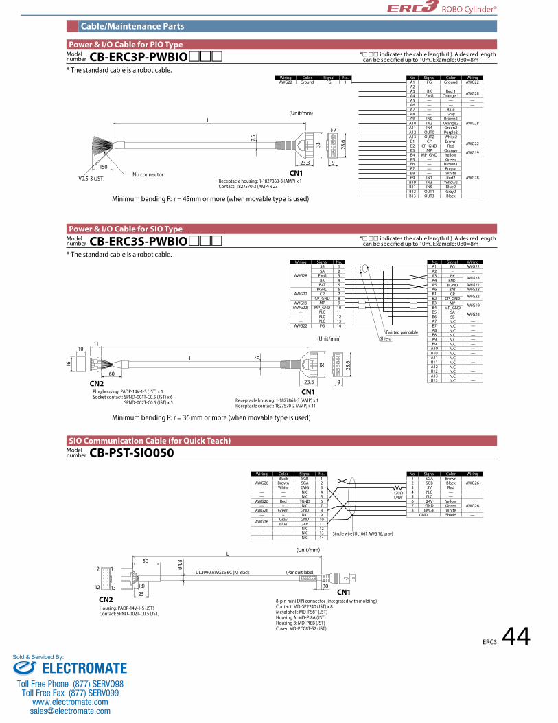
2
12
1
13
50
2530(3)
4.8
9
B A
23.3
CN1
CN1CN2
7.5
33 28.6
150
V0.5-3 (JST)No connector
Minimum bending R: r = 45mm or more (when movable type is used)
Minimum bending R: r = 36 mm or more (when movable type is used)
Receptacle housing: 1-1827863-3 (AMP) x 1Contact: 1827570-3 (AMP) x 23
Housing: PADP-14V-1-S (JST) Contact: SPND-002T-C0.5 (JST)
8-pin mini DIN connector (integrated with molding) Contact: MD-SP2240 (JST) x 8 Metal shell: MD-PS8T (JST)Housing A: MD-PI8A (JST)Housing B: MD-PI8B (JST)Cover: MD-PCC8T-S2 (JST)
UL2990 AWG26 6C (K) Black (Panduit label)
Single wire (UL1061 AWG 16, gray)
120Ω1/4W
L
L
(Unit/mm)
(Unit/mm)
No. Signal Color WiringA1 FG Ground AWG22A2 — — —A3 BK Red 1 AWG28A4 EMG Orange 1A5 — — —A6 — — —A7 — Blue
AWG28
A8 — GrayA9 IN0 Brown2
A10 IN2 Orange2A11 IN4 Green2A12 OUT0 Purple2A13 OUT2 White2B1 CP Brown AWG22B2 CP_GND RedB3 MP Orange AWG19B4 MP_GND YellowB5 — Green
AWG28
B6 — Brown1B7 — PurpleB8 — WhiteB9 IN1 Red2
B10 IN3 Yellow2B11 IN5 Blue2B12 OUT1 Gray2B13 OUT3 Black
Wiring Color Signal No.AWG22 Ground FG 1
Wiring Color Signal No.
AWG26Black SGB 1
Brown SGA 2White EMG 3
— — N.C 4— — N.C 5
AWG26 Red TGND 6— − N.C 7
AWG26 Green GND 8— − N.C 9
AWG26 Gray GND 10Blue 24V 11
— — N.C 12— — N.C 13— — N.C 14
Twisted pair cableShield
Wiring Signal No.
AWG28
SB 1SA 2
EMG 3BK 4
BAT 5
AWG22BGND 6
CP 7CP_GND 8
AWG19(AWG22)
MP 9MP_GND 10
— N.C 11— N.C 12— N.C 13
AWG22 FG 14
SignalA1 AWG22A2 −A3 AWG28A4A5 AWG22A6 AWG28B1 AWG22B2B3 AWG19B4B5 AWG28B6A7 —B7 —A8 —B8 —A9 —B9 —
A10 —B10 —A11 —B11 —A12 —B12 —A13 —B13 —
No. Signal Color Wiring1 SGA Brown
AWG262 SGB Black3 5V Red4 N.C —5 N.C —6 24V Yellow
AWG267 GND Green8 EMGB White
GND Shield —
44ERC3
6
923.3
CN1CN2
33
Plug housing: PADP-14V-1-S (JST) x 1 Socket contact: SPND-001T-C0.5 (JST) x 6 SPND-002T-C0.5 (JST) x 5 Receptacle housing: 1-1827863-3 (AMP) x 1
Receptacle contact: 1827570-2 (AMP) x 11
L
(Unit/mm)
28.6
60
1110
16
ROBO Cylinder®
Cable/Maintenance Parts
Power & I/O Cable for PIO Type* indicates the cable length (L). A desired length
* indicates the cable length (L). A desired length
CB-ERC3P-PWBIOModel number
CB-ERC3S-PWBIOModel number
CB-PST-SIO050Model number
Power & I/O Cable for SIO Type
SIO Communication Cable (for Quick Teach)
* The standard cable is a robot cable.
* The standard cable is a robot cable.FG−
BKEMG
BGNDBATCP
CP_GNDMP
MP_GNDSASBN.CN.CN.CN.CN.CN.CN.CN.CN.CN.CN.CN.CN.CN.C
WiringNo.
ELECTROMATEToll Free Phone (877) SERVO98
Toll Free Fax (877) SERV099www.electromate.com
Sold & Serviced By:

45 ERC3
ROBO Cylinder®
Options
PIO Converter <RCB-CV>
■Features
When connected to the PIO converter, the ERC3 series can demonstrate functions equivalent to the RCP4 controller "PCON-CA." Use the PIO converter if you want to configure a high-function system using the ERC3 series, use the absolute function or monitor the status of the actuator.
Realizing controller functions of the next higher class with the ERC3 series
ERC3Home return
Home return operation is no longer required
In the simple absolute mode…
The actuator can be operated immediately after reconnecting the power.
■ Increased maximum number of positioning points
While the maximum number of positioning points supported by the ERC3 series’ built-in controller is 16, it increases to 512 when the PIO converter is connected.Connecting the PIO converter also increases the numbers of I/O signals, allowing for complex controls and connection with peripheral equipment.
■ Supporting the simple absolute mode The standard encoder of the ERC3 series is of incremental type. Once the power is turned off, therefore, the actuator’s current position is lost and home return operation will be required next time the actuator is started. When the PIO converter is connected, the ERC3 lets you select the simple absolute mode. Home return operation is not required while the encoder is in the simple absolute mode, because the current position is retained.* To use the simple absolute function, the PIO converter must be of the simple absolute type (equipped with the simple absolute battery) and the actuator must also be of the simple absolute specification. * Among the diffrent I/O types, only the serial communication type supports the simple absolute function.
■ Status LEDs indicating the operating status of the actuator The PIO converter lets you check the following status using the status LEDs provided on the front panel (optional).
■ Command current ratio level ■ PIO input terminal status ■Alarm code ■ PIO output terminal status
Status LEDs
16 LEDs indicate the operating status of
the actuator.
ELECTROMATEToll Free Phone (877) SERVO98
Toll Free Fax (877) SERV099www.electromate.com
Sold & Serviced By:

46ERC3
ROBO Cylinder® ROBO Cylinder®
RCBSeries Type I/O type I/O cable length Simple absolute
function supported
CV Built-in power cutoff relay type (standard)
CVG External power cutoff relay type
NP NPN specification (without monitoring LEDs)
PN PNP specification (without monitoring LEDs)
NPM NPN specification (with monitoring LEDs)
PNM PNP specification (with monitoring LEDs)
0 No cable
2 With 2m cable
3 With 3m cable
5 With 5m cable
(No entry) Simple absolute function not supported (for incremental specification only)
AB Simple absolute function supported (with simple absolute battery)
ABUN Simple absolute function supported (without simple absolute battery
* Select "NPM/PNM" if you want to use the functions of monitoring LEDs on the front panel.
Item DescriptionNumber of connected axes ERC3 1 axisPower supply voltage 24VDC±10%Control power capacity 0.8A max.Heat output 1.3WMomentary power failure resistance 500μs max.Serial communication interface(SIO port)
RS485: 1 channel (conforming to Modbus protocol RTU/ASCII) / Speed: 9.6 to 230.4 kbpsActuators can be controlled via serial communication.
External interface Dedicated 24-VDC signal input/output (NPN or PNP selected)—Up to 16 input points, up to 16 output points / Cable length: 10 m max.Data setting/input method PC software, touch-panel teaching pendantOperation Mode Positioner modeNumber of positions in positioner mode Standard 64 points, maximum 512 points Note) Positioning points vary depending on the selected PIO pattern.
LED display (installed on the front panel)
Status indicator LED - Steady green light: Servo ON / Blinking green light: Auto servo OFF / Steady red light: Alarm present Absolute battery status indicator LED - Green: Fully charged / Orange: Charging / Red: Not connectedAbsolute reset status LED - Green: Absolute reset complete / Red: Absolute reset not yet complete LED0 to LED15 (optional): 4 different statuses can be indicated by changing the switch setting. Command current ratio, alarm code, PIO input status, PIO output status
Electromagnetic brake forced release switch (installed on the front panel) Switched between NOM (standard) and BK RLS (forced releases)Isolation resistance 500VDC, 10MΩ or moreElectric shock protection mechanism Class I basic isolationCooling method Natural air cooling
Environment
Ambient operating temperature 0 to 40°Ambient operating humidity 85%RH or less (non-condensing)Ambient storage temperature −20 to 70° (excluding batteries)Operating altitude Altitude 1000m or lessProtection degree IP20
Vibration resistanceNumber of vibrations: 10 to 57 Hz / Amplitude: 0.075 mm Number of vibrations: 57 to 150 Hz / Acceleration: 9.8 m/s2 Sweep time in X/Y/Z directions: 10 minutes / Number of sweeps: 10 times
Weight 103g or less, or 287g (including 190g for the battery) or less for the simple absolute specificationExternal Dimensions 25W×90H×98D
Consumable partsRTC backup capacitor: Approx. 5 years*Drive-source cutoff relay: Approx. 100,000 actuationsAbsolute battery: Approx. 3 years
■Base Specifications
*When the power is supplied 12 hours a day at an ambient temperature of 40°C and the actuator is stopped (power turned off ) 12 hours a day in an ambient temperature of 20°C.
■Model Configuration
NOMRLS Brake release switch
■ Brake release switch for at-will release of the brakeIf your ERC3 actuator comes with a brake, the brake can be turned on/off freely using the brake release switch on the front panel of the PIO converter. To release the brake, turn the switch to the "RLS" position.* If the actuator is used vertically, hold the actuator in place before releasing the brake.
Release the brake: RLSNormal: NOM
■ Calendar function for checking when errors occurredThe PIO converter has a calendar function that lets you check the details of past alarms, such as when each alarm occurred, by connecting the teaching pendant and PC software to the PIO converter. This function is useful when analyzing alarms.
ELECTROMATEToll Free Phone (877) SERVO98
Toll Free Fax (877) SERV099www.electromate.com
Sold & Serviced By:

47 ERC3
ROBO Cylinder®
No. Signal name
Cable color Wiring
1A - Brown - 1
Flat cable A (crimped)
2A - Red - 13A - Orange - 14A - Yellow - 15A IN0 Green - 16A IN1 Blue - 17A IN2 Purple - 18A IN3 Gray - 19A IN4 White - 1
10A IN5 Black - 111A IN6 Brown - 212A IN7 Red - 213A IN8 Orange - 214A IN9 Yellow - 215A IN10 Green - 216A IN11 Blue - 217A IN12 Purple - 218A IN13 Gray - 219A IN14 White - 220A IN15 Black - 2
No. Signal name
Cable color Wiring
1B OUT0 Brown - 3
Flat cable B (crimped)AWG 28
2B OUT1 Red - 33B OUT2 Orange - 34B OUT3 Yellow - 35B OUT4 Green - 36B OUT5 Blue - 37B OUT6 Purple - 38B OUT7 Gray - 39B OUT8 White - 3
10B OUT9 Black - 311B OUT10 Brown - 412B OUT11 Red - 413B OUT12 Orange - 414B OUT13 Yellow - 415B OUT14 Green - 416B OUT15 Blue - 417B — Purple - 418B — Gray - 419B — White - 420B — Black - 4
L
20A
1A
20B
1B
No connector
No connector
Flat cable (20 cores) x 2
Half-pitch MIL socket: HIF6-40D-1.27R (Hirose)
HIF6-40D-1.27R
A
B
* indicates the cable length (L). A desired length can be specified up to 10m. Example: 080=8mCB-PAC-PIOModel
number
I/O Flat Cable
98
25
90
35.4
(Wid
th o
f DIN
rail:
35m
m)
40 fr
om ce
nter
of D
IN ra
il (5
)(1
0)
80
Moving band of DIN lock tab: 5mm
4
■Connection Example
■External Dimensions
■Standard PricesPower cut-off relay Monitoring LEDs Positoning method Model Numbers Standard Prices
Built-in type
N/AIncremental specification RCB-CV-(NP/PN)-➀ —Simple absolute specification (with battery) RCB-CV-(NP/PN)-➀ -AB —Simple absolute specification (without battery) RCB-CV-(NP/PN)-➀ -ABUN —
AvailableIncremental specification RCB-CV-(NPM/PNM)-➀ —Simple absolute specification (with battery) RCB-CV-(NPM/PNM)-➀ -AB —Simple absolute specification (without battery) RCB-CV-(NPM/PNM)-➀ -ABUN —
External type
N/AIncremental specification RCB-CVG-(NP/PN)-➀ —Simple absolute specification (with battery) RCB-CVG-(NP/PN)-➀ -AB —Simple absolute specification (without battery) RCB-CVG-(NP/PN)-➀ -ABUN —
AvailableIncremental specification RCB-CVG-(NPM/PNM)-➀ —Simple absolute specification (with battery) RCB-CVG-(NPM/PNM)-➀ -AB —Simple absolute specification (without battery) RCB-CVG-(NPM/PNM)-➀ -ABUN —
*➀ in the model numbers below represents the number indicating I/O cable length.
Option
Simple absolute battery(absolute specification)
I/O flat cable<Model number: CB-PAC-PIO>Standard lengths: 2 m/3 m/5 m
24-VDC power supply <Model number: PS-241 (100-V input)><Model number: PS-242 (200-V input)>
•ThePIOconverterisinstalledonaDINrail.•TheabsolutebatteryisattachedonthesidefaceofthePIO converter using a Velcro tape.
PC software (See P54)
PC software for ROBO Cylinder® * The cable is supplied with the PC software. (RS 232 connection version) <Model number: RCM-101-MW> (USB connection version) <Model number: RCM-101-USB> MEC PC software * A separate cable is required.
Teaching pendant(See P51~54.)<Model number: CON-PTA ><Model number: SEP-PT><Model number: RCM-PST>
PIO converter
PLC
ERC3
Power & I/O cable for SIO type <Model number: CB-ERC3S-PWBIO>Standard lengths: 1 m/3m/5mRefer to P. 44 for the maintenance cable.
Option
Option
Supplied with PIO converter
Supplied with PIO converter
Supplied with Actuator
ELECTROMATEToll Free Phone (877) SERVO98
Toll Free Fax (877) SERV099www.electromate.com
Sold & Serviced By:

48ERC3
ROBO Cylinder®
■Features •Usethepositionadjustmentswitchesonthefrontpaneltojogtheactuator •Thebrakereleaseswitchforeachaxisisprovidedonthefrontpanel
RCMSeries Controller type I/O signal pattern
■Model Configuration
The ERC3 gateway unit lets you connect up to four ERC3 actuators to implement the gateway function. The gateway unit connects to a PLC or other host control system via a field network. It supports seven network protocols (CC-Link, DeviceNet, PROFIBUS-DP, MECHATROLINK-II, CompoNet, EtherCAT, EtherNet/IP).
Gateway Unit <RCM-EGW>
■Base Specifications
Note) Approx. 50 μs of rush current flows after the power is turned on.
Item Description
Number of controlled axes Up to 4 axes
Control/motor power-supply voltage 24 VDC ±10%
Control power capacity 1 A max.
Load current (per axis)
High-output setting enabled 3.5 A rated/4.2 A max.
High-output setting disabled 1.2 A rated/2.2 A max.
Brake release power capacity (per axis) 0.15 A max.
Rush current (Note) 60 A max.
Cable length between actuator and gateway unit 10 m max. (A dedicated cable is used)
Number of positioning pointsUp to 512 points (Unlimited in the simple direct mode or direct numerical specification mode)(Note) The number of positioning points varies depending on the operation pattern selected by the parameter.
Electromagnetic brake forced release The electromagnetic brake for each axis can be released using the applicable brake forced release switch provided on the front panel.
Environment
Ambient operating temperature 0~40o
Ambient operating humidity 85% RH max. (Non-condensing)
Protection class IP20
EGW Built-in power cutoff relay type
EGWG External power cutoff relay type
CC CC-Link
DV DeviceNet
PR ProfiBus
ML MECHATROLINK-II (To be released soon)
CN CompoNet
EC EtherCAT (To be released soon)
EP EtherNet/IP
Common LED indicators
Position adjustment switches
Brake release switch
Axis-specific LED indicators
■Standard Price
(*) To be released soon
Built-in power cutoff relay type External power cutoff relay typeModel Standard price Model Standard price
CC-Link connection specification RCM-EGW-CC — RCM-EGWG-CC —DeviceNet connection specification RCM-EGW-DV — RCM-EGWG-DV —ProfiBus connection specification RCM-EGW-PR — RCM-EGWG-PR —MECHATROLINK-II connection specification (*) RCM-EGW-ML — RCM-EGWG-ML —CompoNet connection specification RCM-EGW-CN — RCM-EGWG-CN —EtherCAT connection specification (*) RCM-EGW-EC — RCM-EGWG-EC —EtherNet/IP connection specification RCM-EGW-EP — RCM-EGWG-EP —
Options
ELECTROMATEToll Free Phone (877) SERVO98
Toll Free Fax (877) SERV099www.electromate.com
Sold & Serviced By:

49 ERC3
ROBO Cylinder®
CON Type Specifications O: Supported X: Not supported
ROBO Cylinder function
Operation pattern (PIO pattern)
0 1 2 3 4 5
Positioning mode Teaching mode 256-point mode 512-point mode Solenoid valve mode 1 Solenoid valve mode 2
Home return operation (Note 1)
Positioning operation
Speed & acceleration/deceleration setting
Pitch feed (inching)
Push-motion operation
Speed change while moving
Operation at different acceleration/speed
Pause (Note 2)
Zone signal output
PIO pattern selection
MEC Type Specifications
ROBO Cylinder functionOperation pattern
1-input, 2-point move 2-input, 3-point move
Home return operation (Note 1) (Note 1)
Positioning operation
Speed & acceleration/deceleration setting
Pitch feed (inching)
Push-motion operation
Speed change while moving
Operation at different acceleration/speed
Pause
Zone signal output
■Operation Mode
■Control Signals in the Remote I/O Mode
Note 1) Switched using the ERC3’s PIO pattern parameter. Note 2) Switched using the ERC3’s operation pattern parameter.
Note 1) Home return is performed with the first move command. Note 2) Supported if ERC3 Parameter No. 27, “Move command type” is set to “0.”
Note 1) Home return is performed with the first move command.
Operation pattern Description
Positioner 1/simple direct mode In the positioner 1 mode, position data of up to 512 points can be registered to stop the actuator at any of the registered positions. The current position can also be monitored. In the simple direct mode, the target position can be specified directly by entering a value. The current position can also be monitored.
Direct numerical specification modeThe target position, speed, acceleration/deceleration and push-current limiting value can be each specified by entering a value. In addition to the current position, the current speed and command current value can also be monitored.
Positioner 2 modeIn this mode, the actuator is operated using the position data of up to 512 points set in the position table. The current position cannot be monitored. The functions available in this mode are the same as those provided in the positioner 1 mode, except that less amount of data can be sent/received.
Positioner 3 modeIn this mode, the actuator is operated using the position data of up to 256 points set in the position table. The current position cannot be monitored. The amount of data sent/received in this mode is further less than that in the positioner 2 mode, and the actuator is controlled using the minimum signals required for positioning.
Remote I/O The same six functions (Note 1) available with the PIO specification (CON type) can be controlled. The same two functions (Note 2) available with the PIO specification (MEC type) can be controlled.
The table below lists the ERC3 functions that can be controlled in each type.
ELECTROMATEToll Free Phone (877) SERVO98
Toll Free Fax (877) SERV099www.electromate.com
Sold & Serviced By:
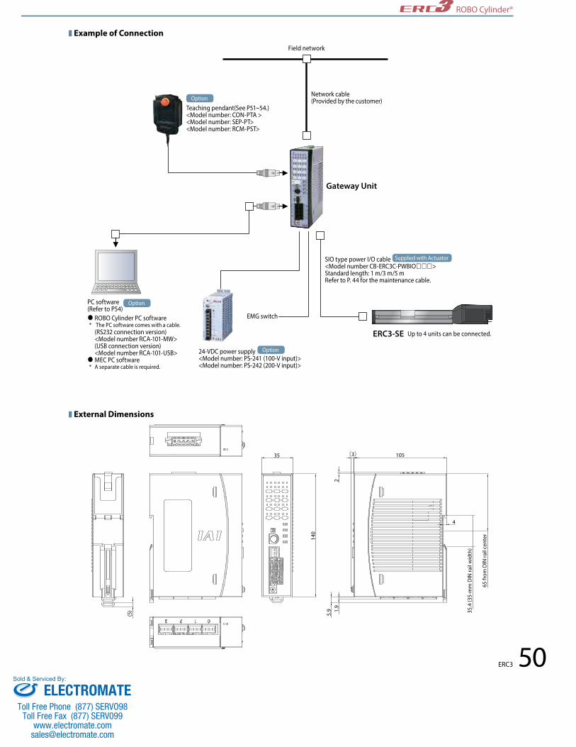
50
ROBO Cylinder®
ERC3
35 105
140
4
65 fr
om D
IN ra
il ce
nter
35.4
(35-
mm
DIN
rail
wid
th)
(3)
(5)
21.
95.
9
■Example of Connection
■External Dimensions
Field network
EMG switch
Network cable (Provided by the customer)
24-VDC power supply <Model number: PS-241 (100-V input)><Model number: PS-242 (200-V input)>
PC software (Refer to P54) ROBO Cylinder PC software * The PC software comes with a cable. (RS232 connection version) <Model number RCA-101-MW> (USB connection version) <Model number RCA-101-USB> MEC PC software * A separate cable is required.
Teaching pendant(See P51~54.)<Model number: CON-PTA ><Model number: SEP-PT><Model number: RCM-PST>
Gateway Unit
ERC3-SE Up to 4 units can be connected.
SIO type power I/O cable <Model number CB-ERC3C-PWBIO>Standard length: 1 m/3 m/5 mRefer to P. 44 for the maintenance cable.
Option
Option
Option
Supplied with Actuator
ELECTROMATEToll Free Phone (877) SERVO98
Toll Free Fax (877) SERV099www.electromate.com
Sold & Serviced By:

Teaching pendantController type CON-PTA RCM-PST SEP-PT
CON type —MEC type
PC software Controller type RCM-101-MW RCM-101-USB MEC PC software
CON type —MEC type — —
RCMSeries Unit name Input
power supplyPanel
language
PST Product unit
PS Power-supply unit0 24 VDC (24-V power-supply specification,
without power-supply unit)
1 Single-phase 100 to 115 VAC (100-V power-supply specification)
2 Single-phase 100 to 230 VAC (200-V power-supply specification)
EU Single-phase 100 to 230 VAC (200-V power-supply specification for Europe)
(No entry) Japanese version
ENG English version
Item Description
Product name 24-VDC specification 100-VDC specification 200-VDC specification 200-V power-supply specification for Europe (Note 2)
Product model RCM-PST-0 RCM-PST-1 RCM-PST-2 RCM-PST-EU
Productconfiguration
Teaching pendant RCM-PST-0
Power-supply unit −(Teaching pendant only) RCM-PS-1 RCM-PS-2 RCM-PS-EU
Power supply voltage 24 VDC±10%(DC 21.6V to DC 26.4V)
Single-phase 100 to 115 VAC±10%
(AC 90V to AC 126.5V)
Single-phase 100 to 230 VAC±10%
(AC 90V to AC253 V)
Single-phase 100 to 230 VAC±10%
(AC90V~AC253V)
Load capacity (motor power capacity) of connected ERC3(Note 1)
ERC3 Rated Maximum 42P 1.2A 2.0A56P 1.2A 2.0A
Number of controlled axes 1 axis
Environment conditionsOperating temperature range: 0 to 40°C
Operating humidity range: 85% RH or less (non-condensing)Storage temperature range: -20°C to 70°C
Protection degree IP20Power-supply frequency 50Hz/60HzPollution degree Pollution degree 2Leak current — 0.5mA max 0.75mA maxCooling method Natural air cooling
Cable lengthActuator cable: 10m or less
AC cable: 2mSIO communication cable (optional): 5m
Product size 65 (W) x 157 (H) x 21.6 (D) 65 (W) x 157 (H) x 64.4 (D)Weight *Excluding connection cables 120g 540g 535gStandard price — — — —
Load capacity (motor power capacity) of connected ERC3(Note 1)
ERC3 Rated Maximum 42P 1.2A 2.2A56P 1.2A 2.2A
51 ERC3
ROBO Cylinder®
Notes on Selecting Teaching Pendant and PC Software
Options
With the ERC3 series, usable teaching pendant and PC software vary depending on the controller type (CON type/MEC type). Refer to P.5 for controller types.
■Features •User-friendlypanelsheetswitchesandknobsletyoucomplete the settings in no time. •Thesmallpendantcanbeheldinahand. •Separatepower-supplyunit
■Model configuration
■Base Specifications
: All functions are supported / : Limited functions are supported (home return, servo ON/OFF, JOG+, JOG-, stop (press and hold to reset alarms))
A teaching pendant equipped with intuitive operation buttons and acceleration/speed knobs that can be used easily even by mechanical engineers and those who never operated a robot before.
Quick Teach <RCM-PST>
Note 1) If an ERC3 actuator whose high-output setting is enabled is used to perform test run using the Quick Teach connected to the above power-supply unit, the ERC3 may not operate as specified. (Position data can be edited without problems.) If test run is performed with the actuator’s high-output setting enabled, connect a 24-VDC power supply to the Quick Teach. In this case, disconnect the power-supply unit. Note 2) The CE Mark-compliant 200-V power-supply specification for Europe will be released soon.
ELECTROMATEToll Free Phone (877) SERVO98
Toll Free Fax (877) SERV099www.electromate.com
Sold & Serviced By:

Brake EMG
Manual mode
Auto
FWD BACK
RUN STOP
Test run
EWDPOS
MIDDLEPOS
BACKPOS
Setting
SERVOON/OFF
SAVE
JOG_ JOG+
HOME
TEACHMODE
MANUAL
Ext.start
Accel Speed
24V input
Alart Power
Accel & Speed
Position
STOPPOS NUM
to Controller
3pnt 2pnt Complete
Stop pos.
ManuCont
Pos.adj
Nom
Power-supply unit
21.6
65
157
64.4
Brake EMG
Manual mode
Auto
FWD BACK
RUN STOP
Test run
EWDPOS
MIDDLEPOS
BACKPOS
Setting
SERVOON/OFF
SAVE
JOG_ JOG+
HOME
TEACHMODE
MANUAL
Ext.start
Accel Speed
24V input
Alart Power
Accel & Speed
Position
STOPPOS NUM
to Controller
3pnt 2pnt Complete
Stop pos.
ManuCont
Pos.adj
NomBrake EMG
Manual mode
Auto
FWD BACK
RUN STOP
Test run
EWDPOS
MIDDLEPOS
BACKPOS
Setting
SERVOON/OFF
SAVE
JOG_ JOG+
HOME
TEACHMODE
MANUAL
Ext.start
Accel Speed
24V input
Alart Power
Accel & Speed
Position
STOPPOS NUM
to Controller
3pnt 2pnt Complete
Stop pos.
ManuCont
Pos.adj
Nom
1
6
5
23
4
7
52ERC3
ROBO Cylinder®
Name and Function of Each Part/External Dimensions
Shown above are the external dimensions of the Quick Teach with power-supply unit (model number: RCM-PST-1/2/EU). The 24-V power-supply specification (model number: RCM-PST-0) has no power-supply unit.
<Quick Teach and Model Numbers>
Model number: RCM-PST-0(24-VDC specification)
Model number: RCM-PST-1 RCM-PST-2 RCM-PST-EU(Power-supply unit specifications)
ERC3 connector ............................ For cable connection with the ERC3. External 24-V connector ........... 24 VDC±10%. * Supplied with a plug connector. Emergency stop connector ..... Connect an emergency stop switch. * Supplied with a plug connector.Brake switch .................................. Forced release switch for an actuator with brake.
AC input cable .............................. Single-phase 100 or 230-V input. * Varies depending on the product. Wall-mounting hook .................. The hook can be secured with M3 or equivalent screws or bolts (screw head size: 06 or less). Operation switches ..................... Panel sheet switches
123
4
6
7
5
24-VDC power supply
< Model number: PS-241 (100-V input) >< Model number: PS-242 (200-V input) >
ERC3
ERC3
Power & I/O cable for SIO type <Model number: CB-ERC3S-PWBIO>Standard lengths: 1m/3m/5mRefer to P. 44 for the maintenance cable.
Quick Teach RCM-PST-0
Quick Teach RCM-PST-1, RCM-PST-2, RCM-PST-EU
AC power supply
Power & I/O cable for SIO type <Model number: CB-ERC3S-PWBIO>Standard lengths: 1m/3m/5mRefer to P. 44 for the maintenance cable.
<Using a 24-VDC power supply>
<Using a 100/200-VAC power supply>
■Connection Example
■Supplying power from the Quick Teach to the ERC3
Option
Supplied with Actuator
Supplied with Actuator
ERC3
Quick Teach RCM-PST-0
S10 communication cable<Model number: CB-PST-SIO050>Refer to P. 44 for details on the cable.
Power & I/O cable for PIO type <Model CB-ERC3P-PWBIO>Standard lengths: 1m/3m/5mRefer to P. 44 for the maintenance cable.
24-VDC power supply <Model number: PS-241 (100-V input)><Model number: PS-242 (200-V input)>
■Connecting the Quick Teach to the ERC3 supplied with power
Option
Option
Supplied with Actuator
ELECTROMATEToll Free Phone (877) SERVO98
Toll Free Fax (877) SERV099www.electromate.com
Sold & Serviced By:

CON-PTA
Item DescriptionModel number CON-PTA-C-ENG CON-PDA-C-ENG CON-PGA-C-S-ENG
Type Standard type Enable switch type Safety-category compliant typeConnectable controllers ACON/PCON/SCON/RACON/RPCON/MSCON ASEP/PSEP/MSEP/DSEP AMEC/PMEC ERC2 (*1) /ERC33-position enable switch
Functions
•Positiondatainput/editing•Movingfunction(movingtosetpositions,jogging/inching)•Parameterediting•Monitoring(currentposition,currentspeed,I/Osignals,alarmcode,alarmgenerationtime)•Saving/readingdatato/fromexternalSDcards(positiondataparameters,alarmlist)•Takttimeminimizationfunction•Maintenanceinformation(totalnumberofmovements,totaldistancetravelled,etc.)
Display 65536 colors (16-bit colors), white LED backlightAmbient operating temperature/humidity 0 to 50°C, 20 to 80% RH (non-condensing)
Environmental resistance IP40 or equivalentMass Approx. 570g Approx. 600g
Cable length 5m
Accessories Stylus StylusStylus, TP adapter (Model number: RCB-LB-TG)
Dummy plug (Model number: DP-4)Controller cable (Model number: CB-CON-LB005)
Stylus
Wall-mounting hook
Enable switch
14 24
10 4
98
Emergency stop button
Operation screen
13292.1
180
5m
(50)
Developed based on the design of the popular CON-PT series adopting an easy-to-use interactive touch-panel menu screen, this new data input device supports various functions offered by the ERC3 series controller.
1. Color screen for greater ease of view2. Supporting the takt time minimization function and maintenance information checking/ input functions of the ERC3 series3. Position, parameters and other data can be saved in a SD card 4. Built-in clock function records the date & time of each event; data can then be saved in a SD card.
*1 Among the ERC2 series, only the actuators bearing 4904 or greater number stamped on the serial number label can be connected.
Name of Each Part/External Dimensions
Option•Strap(Modelnumber:STR-1)
Touch-panel Teaching Pendant for Position Controller
53 ERC3
ROBO Cylinder®
Options
Name of Eech Part
Model Numbers/Specifications
ELECTROMATEToll Free Phone (877) SERVO98
Toll Free Fax (877) SERV099www.electromate.com
Sold & Serviced By:

RS232 conversion adapter RCB-CV-MW
External device communication cable CB-RCA-SIO050
0.3m
5m
PC software (CD)
External device communication cable CB-RCA-SIO050
USB conversion adapter RCB-CV-USB
USB cableCB-SEL-USB030
3m 5m
PC software (CD)
❚ Features Teaching device offering position input, test run, monitoring and other functions. * This teaching pendant can be used when the ERC3’s controller type is set to "MEC type."
❚ Features This startup support software provides functions to input positions, perform test runs and monitor data, among others. Incorporating all functions needed to make adjustments, this software helps shorten the initial startup time. * This software can be used when the ERC3’s controller type is set to "CON type."
❚ Model number RCM-101-MW (With external device communication cable + RS232 conversion unit)❚ Configuration
❚ Model number RCM-101-USB (With external equipment communication cable + USB conversion adapter + USB cable)❚ Configuration
❚ Configuration
❚ Specifications
SEP-PT version 3.00 or later is supported.
PC software version 8.03.00.00 or later is supported.
The MEC PC software can be used with the version
2.00.00.00 or later.
5m
SEP-PT132 92.1
Item SEP-PTData input
Actuator operation
Ambient operating temperature/humidity Temperature 0 to 40oC, humidity 85%RH or less
Operating ambience Free from corrosive gases or significant powder dust.
Protection degree IP40
Mass Approx. 550g
Cable length 5m
Display 3-color LED touch panel with backlight
Standard price —
PC connection method Model Name Price
RS232CB-RCA-SIO050 External device communication cable —RCB-CV-MW RS232 conversion adapter —
USBCB-RCA-SIO050 External device communication cable —RCB-CV-USB USB conversion adapter —CB-SEL-USB030 USB cable — 54ERC3
ROBO Cylinder®
Options
Touch-panel Teaching Pendant for Position Controller SEP-PT
■PC Software (Windows Only)
■MEC PC SoftwareYou can change the stop position data, perform test run and do many other things on a PC using the MEC PC software. This software also lets you use the middle stop function, perform push-motion operation, change the coordinates, etc., with ease. The MEC PC software can be downloaded on the IAI’s website.
* This software can be used when the ERC3’s controller type is set to "MEC type."
IAI’s website: www.intelligentactuator.com
The cable supplied with the above "PC software (RCM-101-MW/RCM-101-USB)" can be used to connect the PC and ERC3 series. To purchase a cable separately, select an appropriate cable/adapter by referring to the table below.
ELECTROMATEToll Free Phone (877) SERVO98
Toll Free Fax (877) SERV099www.electromate.com
Sold & Serviced By:

CJ0184-4A-UST-2-0214
IAI America, Inc.Headquarters: 2690 W. 237th Street, Torrance, CA 90505 (800) 736-1712
1261 Hamilton Parkway, Itasca, IL 60143 (800) 944-0333 1220 Kennestone Circle, Suite 108, Marietta, GA 30066 (888) 354-9470
www.intelligentactuator.com
IAI Industrieroboter GmbHOber der Röth 4, D-65824 Schwalbach am Taunus, Germany
IAI Robot (Thailand), CO., Ltd.825 PhairojKijja Tower 12th Floor, Bangna-Trad RD.,Bangna, Bangna, Bangkok 10260, Thailand
The information contained in this product brochure may change without prior notice due to product improvements.
ELECTROMATEToll Free Phone (877) SERVO98
Toll Free Fax (877) SERV099www.electromate.com
Sold & Serviced By: