iacmi: a disruptive moment in automotive history · iacmi: a disruptive moment in automotive...
TRANSCRIPT

IACMI: A Disruptive Moment
in Automotive History
Craig Blue
Chief Executive Officer

2IACMI Overview
January 9, 2015: President Obama
Announces New Composite Institute
“…and today, we’re proud to announce our
latest manufacturing hub, and it is right
here in Tennessee. Led by the University
of Tennessee–Knoxville, the hub will be
home to 122 public and private partners
who are teaming up to develop materials
that are lighter and stronger than steel. ”

3IACMI Overview
• Operated by an independent not-for-profit
• Governed by a board of directors
• A wholly owned subsidiary of the University of Tennessee Research Foundation
• Incorporated in the State of Tennessee
• Headquartered in Knoxville, Tennessee
4IACMI Overview
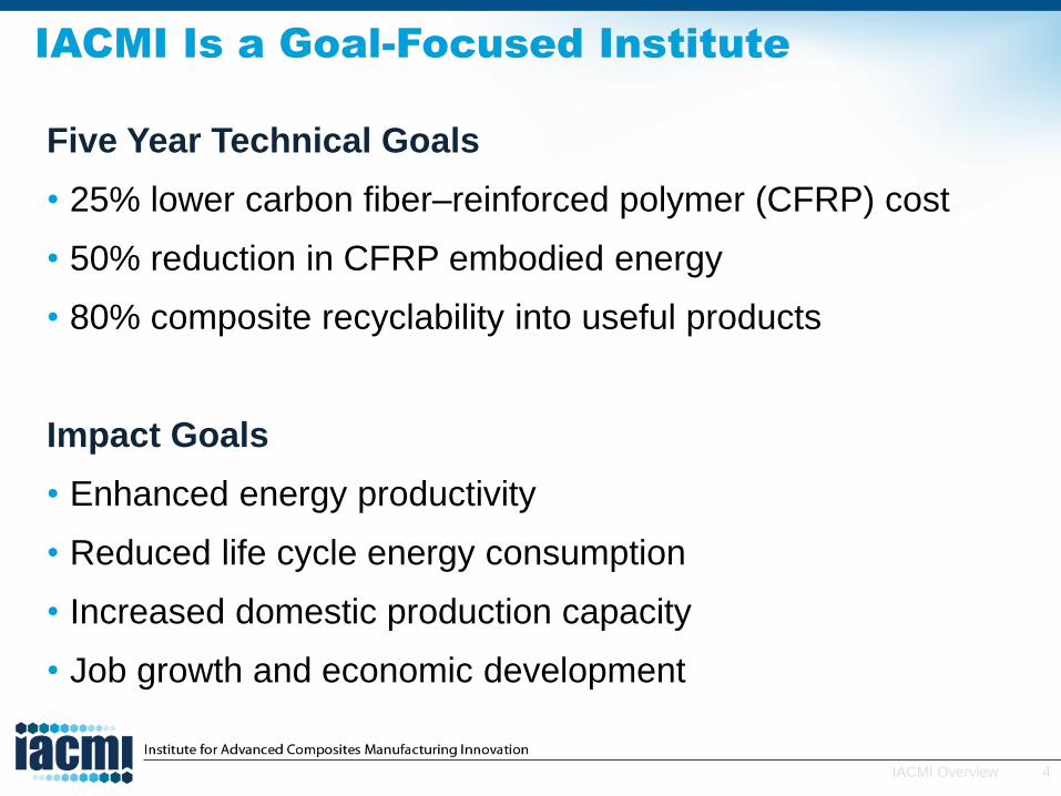
IACMI Is a Goal-Focused Institute
Five Year Technical Goals
• 25% lower carbon fiber–reinforced polymer (CFRP) cost
• 50% reduction in CFRP embodied energy
• 80% composite recyclability into useful products
Impact Goals
• Enhanced energy productivity
• Reduced life cycle energy consumption
• Increased domestic production capacity
• Job growth and economic development
5IACMI Overview
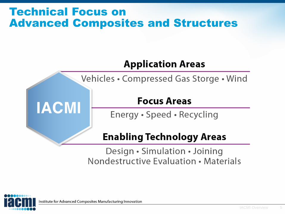
Technical Focus on
Advanced Composites and Structures
6IACMI Overview
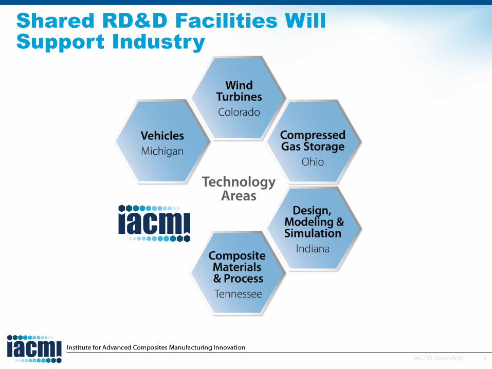
Shared RD&D Facilities Will
Support Industry

7IACMI Overview
Core Partners are Capable and Strategically
Located
>70% of automotive production occurs in IACMI states
Colorado has more blade facilities (factories plus technical centers) than any other state
>60% of manufacturers of compressed gas–fueled vehicles with in half-day drive from IACMI focus areas
>70% of US auto R&D in Michigan alone

8IACMI Overview
Solutionspinning
line Carbon Fiber Technology
Facility Pre-preg
productionpilot/full
scale
Pilot-scalePCM
1,000 ton press
Full ScalePCM
4,000 ton press
Scale-up Across IACMI State Partners
9IACMI Overview
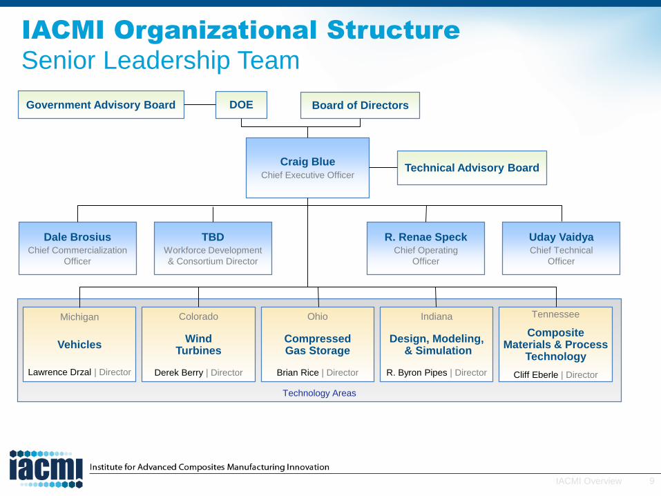
IACMI Organizational Structure
Senior Leadership Team
Technology Areas
Technical Advisory Board
DOE Board of Directors
Michigan
Vehicles
Lawrence Drzal | Director
Colorado
Wind Turbines
Derek Berry | Director
Ohio
CompressedGas Storage
Brian Rice | Director
Indiana
Design, Modeling,& Simulation
R. Byron Pipes | Director
Tennessee
CompositeMaterials & Process
Technology
Cliff Eberle | Director
Craig BlueChief Executive Officer
Dale BrosiusChief Commercialization
Officer
TBDWorkforce Development
& Consortium Director
R. Renae SpeckChief Operating
Officer
Uday VaidyaChief Technical
Officer
Government Advisory Board

10IACMI Overview
IACMI has >190 Supporters and Growing
11IACMI Overview
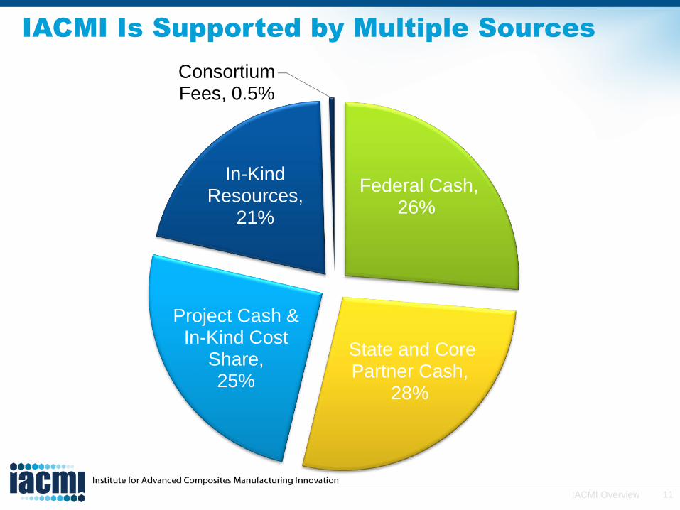
IACMI Is Supported by Multiple Sources
Federal Cash, 26%
State and Core Partner Cash,
28%
Project Cash & In-Kind Cost
Share, 25%
In-Kind Resources,
21%
Consortium Fees, 0.5%

12IACMI Overview
Economic Development Council
A Platform for State Economic Collaboration
Each state deploys
hundreds of millions of dollars annually to create jobs and investment through
• Business services/ incentives
• Venture funds
• Workforce training
• Innovation incubation
Collaboration of state
development leaders seeding economies
worth $2 trillion

13IACMI Overview
Leveraging Core State Partnerships
for STEM and Workforce Development
UniversitiesWorkforceRetraining
K–12Community
Colleges
Internships

14IACMI Overview
An Integrated Approach Is Required
Vehicles Technology Area
Professor Lawrence T. Drzal, Director
Ray Boeman, Associate Director
16IACMI Overview
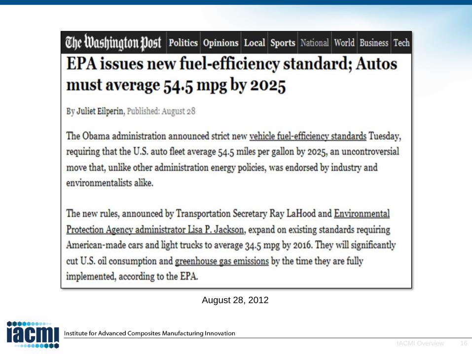
August 28, 2012

17IACMI Overview
Vehicle Response to 54.5mpg Challenge
• Lightweighting is an important end-use energy efficiency strategy in transportation. For example a 10% reduction in vehicle weight can improve fuel efficiency by 6%–8% for conventional internal combustion engines or increase the range of a battery-electric vehicle by up to 10%.
• Composites can offer a range of mass reductions over steel ranging from 25 to 30% (glass fiber systems) up to 60 to 70% (carbon fiber systems).
Specific stiffness and specific strength for various materials:
carbon fiber reinforced polymer (CFRP) composites and
glass fiber reinforced polymer (GFRP) composites.
University of Cambridge, http://wwwmaterials.eng.cam.ac.uk/mpsite/interactive_charts/spec‐spec/basic.html

18IACMI Overview
Why Lightweighting?
“Excess weight kills any self-propelled vehicle. There are a lot of fool ideas about weight . . . Whenever anyone suggests to me that I might increase weight or add a part, I look into decreasing weight and eliminating a part!” – Henry Ford, 1922
Every automotive manufacturer is pursuing lightweightingas a key strategy to reduce fuel consumption—irrespective
of the powertrain technology pathway.

19IACMI Overview
Lightweighting Vehicles
Global Comparison of Light-Duty Vehicle
Fuel Economy/GHG Emissions Standards, International
Council on Clean Transportation, August, 2011
Carbon fiber reinforced polymer (CFRP) composites have the greatest weight reduction potential if cost and
manufacturing issues can be solved.
20IACMI Overview
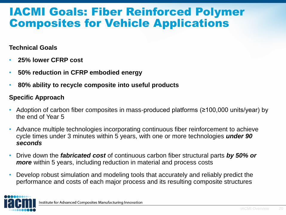
IACMI Goals: Fiber Reinforced Polymer
Composites for Vehicle Applications
Technical Goals
• 25% lower CFRP cost
• 50% reduction in CFRP embodied energy
• 80% ability to recycle composite into useful products
Specific Approach
• Adoption of carbon fiber composites in mass-produced platforms (≥100,000 units/year) by the end of Year 5
• Advance multiple technologies incorporating continuous fiber reinforcement to achieve cycle times under 3 minutes within 5 years, with one or more technologies under 90 seconds
• Drive down the fabricated cost of continuous carbon fiber structural parts by 50% or more within 5 years, including reduction in material and process costs
• Develop robust simulation and modeling tools that accurately and reliably predict the performance and costs of each major process and its resulting composite structures

21IACMI Overview
How Will IACMI Vehicle Technology Area
(VTA) Achieve Its Goals?
• Knowledgeable and dedicated professional staff
• State-of-the art automotive composite process facilities at manufacturing scale
• Integration of participant teams in the vehicle supply chain
– OEM, Tier 1, material suppliers, SMEs
• Identification and support for leading-edge projects
• Access to facilities for proprietary projects
• Workforce development opportunities

22IACMI Overview
>70% of automotive production occurs in IACMI states
>70% of US auto R&D in Michigan alone
Michigan Is Strategically Located and the
Leader in US Auto Production and R&D

23IACMI Overview
State of Michigan Support
• Michigan Economic Development Corporation —MEDC
– Develop automotive strategic plan
• Demographics and vehicle market
• Vehicle design
• Connected vehicles
• Powertrain and propulsion technologies
• Manufacturing and supply chain
• Material and joining technologies
– Establish collaboration center across supply chain
• OEM-tiers-suppliers-tooling-fabricators-design-testing
– Leverage expertise to attract federal and industry investment
– Develop talent in materials engineering, modeling, simulation, systems engineering and skilled trades
• Michigan State, Michigan, Michigan Tech, Wayne State
• Community Colleges: Lansing CC, Macomb CC, Alpena CC
– $15M investment in IACMI-VTA 5 years
Automotive Strategic Plan

24IACMI Overview
Vehicles Technology Area: Resources
Automation processes,
in situ thermoplastic infusion
Models for preforming,
infusion, cure kinetics, performance
High strain rate testing, NDE,
mesoscale molding,
netshape preforming,
ICME processing and performance
Low-cost carbon fiber (LCCF),
lab-scale intermediates and composites fabrication,
NDE,
recycling
• Michigan State University Resources (lab scale)
• Composite Materials and Structures Center
• Composite Vehicles Research Center
• 22,500 ft2 facility for analysis, characterization, processing and testing
• Faculty, research staff, Postdocs, graduate students
• Scale-up facility (MSU operated)
• Located in 40,000 ft2 proximate to
ALMMI/LIFT to foster IMI collaboration
and multi-material solutions
• Centrally located in Detroit
• MI State-(MEDC) funded full-scale
equipment and facilities

25IACMI Overview
MI-Vehicles Technology Area:
MSU Resources and Expertise
• Composite Materials and Structures Center
• Composite Vehicles Research Center
• MSU—Applied Research Laboratory, ITAR/EAR Compliant
– Research, characterization, testing, development facilities
• Polymer composite processing and modeling
• Process development, modeling and manufacturing-liquid systems
• Additive manufacturing of thermoplastic composites
• Multifunctional composites (nanoparticles)
• Joining—adhesive bonding, mechanical fastening, bolt design
• Surface treatments and sizing of reinforcing fibers and adherends
• Biobased structural composites
• Modeling and structural analysis (static, crash, impact, fire, fatigue)
• Dynamic characterization and design
• NDI, NDE in-situ, and remote sensing
26IACMI Overview
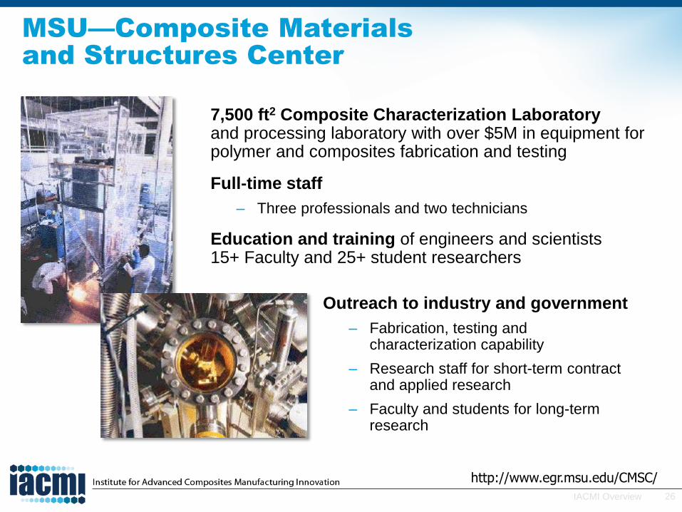
MSU—Composite Materials
and Structures Center
7,500 ft2 Composite Characterization Laboratoryand processing laboratory with over $5M in equipment for polymer and composites fabrication and testing
Full-time staff
– Three professionals and two technicians
Education and training of engineers and scientists 15+ Faculty and 25+ student researchers
http://www.egr.msu.edu/CMSC/
Outreach to industry and government
– Fabrication, testing and characterization capability
– Research staff for short-term contract and applied research
– Faculty and students for long-term research

27IACMI Overview
MSU—Composite Vehicle
Research Center
Center of Excellence for the research, design, and implementation of composites for lightweight, durable, cost-effective, efficient, and safe vehicles
• Emphasis on composite vehicle systems, subsystems, and components
• Intersection of composites and vehicle technologies
• ITAR-compliant off-campus facility
• “Design validated by experiment”
• Integration of analytical, numerical, and experimental approaches
Focal Areas:
• Impact and crash resistance
• Design and manufacturing – liquid molding
• Multifunctional composites
• Composites joining – bonded and bolted
• Multi-scale damage modeling
• Wireless health monitoring
• Structural optimization
28IACMI Overview
Vehicle Scale-up Facility (Detroit Area)
• OEMs and Tier 1 Industries met over a 24 month period to identify what was necessary to achieve large-scale production of polymer composites for automotive applications
• Shared facility located in epicenter of automotive R&D
– Easy and flexible access
• Production-scale equipment to demonstrate production rates >100,000 parts/year
• Automated preprocessing of composite constituents and post-processing of composites parts at scale
• Integrated in-situ recycling of offal

29IACMI Overview
IACMI-VTA Process Capabilities
• Preforming
– Automated cutting
– Thermoplastic tape layup
– Preforming press
– Thermoplastic consolidation
• Finishing
– Waterjet
– Multiaxis trim router
• Large Composite Part Fabrication
– Insert/Overmold Injection Molding (IOIM). Structural injection molding of long fiber reinforced thermoplastics into a cavity with continuous fiber preforms, composites, etc.) has been placed in performance-critical locations.
– High Pressure Resin Transfer Molding (HP-RTM) Structural dry fiber preform is placed into a mold cavity, and a liquefied, reactive resin, such as epoxy or polyurethane, is injected through the preform and cured. Both thermoset and reactive thermoplastics.
– Compression Molding of Continuous Fiber Prepreg (Thermoset, Thermoplastic) SMC processes will be modified to accommodate continuous fiber prepregsthat have been robotically cut, stacked and debulked to reduce waste and increase properties along specific load paths.
• Material formulation
– Hot-melt prepreg line
– Thermoplastic recycling regrind/recompound

30IACMI Overview
Example Project: Compression Molding of
Continuous Fiber Prepreg
Project Elements Addressed by IACMI
• Development of large parts employing CARBON and/or GLASS fiber and unidirectional preform molding of prepregs targeted at 3 min part cycle for parts the size of a roof
• Draping simulation, rheological characterization, property determination to form the basis for process modeling and simulation
• Enhanced robotics for cutting, kitting, and stacking for complex parts at less than 3 min cycle times
• Optimized cutting paths and part design and high-speed tape laying to minimize waste
• Combination of continuous and discontinuous fiber prepreg materials in a single molding process
• Hands-on training of technicians/engineers
• Opportunity for proprietary material and/or process development
Source, Schuler
Source, Composites World

31IACMI Overview
Composite Joint Design and Multi-material Attachment Technology
Project: Develop process-specific joint and interface design incorporating
both adhesive bonding and mechanical fastening for FRP/metal joints
Example Cross-Cutting Project
Adhesive Bonding • Potential reduction in weight & cost
• Preferred over mechanical fastening
• Eliminates stress concentrations due to holes
Types of Adhesive Jointsa) Lap-Joint
b) Double Lap-Joint
c) Butt Joint
d) Scarf Joint
e) Corner/L-joint
f) T-/Pi- Joint
Objectives • Quantify the performance of tailorable, multifunctional,
adhesively bonded structural composite joints. Includes
Pi-, lap-, and dissimilar materials
• Model mechanical response under static and dynamic
conditions
• Develop high speed surface prep and fabrication methods
Mechanical Fastening• Required for repair, reassembly
• FRP composites require special hole design &
fasteners to avoid hole-initiated damage
32IACMI Overview
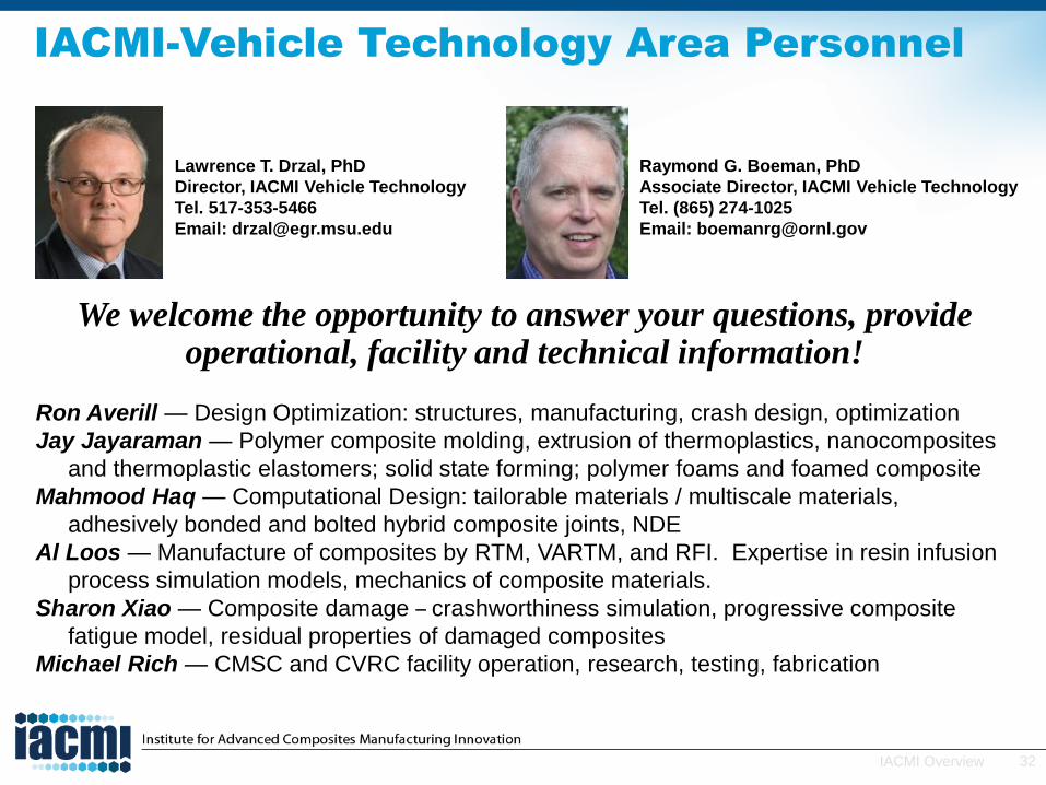
IACMI-Vehicle Technology Area Personnel
We welcome the opportunity to answer your questions, provide operational, facility and technical information!
Ron Averill — Design Optimization: structures, manufacturing, crash design, optimization
Jay Jayaraman — Polymer composite molding, extrusion of thermoplastics, nanocomposites
and thermoplastic elastomers; solid state forming; polymer foams and foamed composite
Mahmood Haq — Computational Design: tailorable materials / multiscale materials,
adhesively bonded and bolted hybrid composite joints, NDE
Al Loos — Manufacture of composites by RTM, VARTM, and RFI. Expertise in resin infusion
process simulation models, mechanics of composite materials.
Sharon Xiao — Composite damage – crashworthiness simulation, progressive composite
fatigue model, residual properties of damaged composites
Michael Rich — CMSC and CVRC facility operation, research, testing, fabrication
Lawrence T. Drzal, PhD
Director, IACMI Vehicle Technology
Tel. 517-353-5466
Email: [email protected]
Raymond G. Boeman, PhD
Associate Director, IACMI Vehicle Technology
Tel. (865) 274-1025
Email: [email protected]

Compressed Gas Storage
Technology Area and Intermediate
Scale Manufacturing
Brian Rice, Director, CGS

34IACMI Overview
Why Ohio?
Ohio ranks #2 in the US in automotive-related employment
60% of compressed gas−fueled vehicle manufacturers within half-day drive from IACMI centers
35IACMI Overview
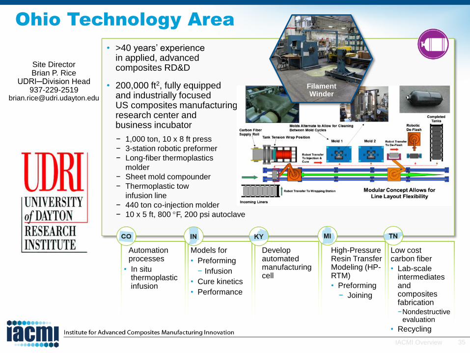
• >40 years’ experiencein applied, advancedcomposites RD&D
• 200,000 ft2, fully equippedand industrially focusedUS composites manufacturingresearch center andbusiness incubator
− 1,000 ton, 10 x 8 ft press
− 3-station robotic preformer
− Long-fiber thermoplastics
molder
− Sheet mold compounder
− Thermoplastic tow
infusion line
− 440 ton co-injection molder
− 10 x 5 ft, 800 F, 200 psi autoclave
Filament Winder
Automation processes
• In situ thermoplastic infusion
Models for
• Preforming
− Infusion
• Cure kinetics
• Performance
Develop automated manufacturing cell
High-Pressure Resin Transfer Modeling (HP-RTM)
• Preforming
− Joining
Low costcarbon fiber
• Lab-scale intermediates and composites fabrication −Nondestructive
evaluation
• Recycling
Site DirectorBrian P. Rice
UDRI─Division Head937-229-2519
Ohio Technology Area

36IACMI Overview
DOE Compressed Gas Storage (CGS) Tank
Targets
Reduce the cost of a type IV hydrogen storage tank by 30% (2018) and 50% (2024) with a capacity of 500,000 units/year
Type IV: An all-composite construction featuring a polymer (typically high-density polyethylene, or HDPE) liner with carbon fiber or hybrid carbon/glass fiber composite. The composite materials carry all of the structural loads.
Fabrication method: Filament winding, a mature industry, 40+ years
The markets: Pressure vessels (2015)*
High-pressure gas storage vessels represent one of the biggest and fastest-growing markets for advanced composites, as transportation markets demand alternative fuels (Compressed natural gas [CNG] and hydrogen) for motive power systems.
*Composites World January 12, 2015

37IACMI Overview
http://www.calstart.org/Libraries/CalHEAT_Documents/Heavy-Duty_NGV_Roadmap_2014.sflb.ashx
KCF = 1000 cubic feet
Reduced Cost of CGS Tanks Enables
Greater Use of Domestic Fuels Such
As Natural Gas
38IACMI Overview
*Composites World January 12, 2015
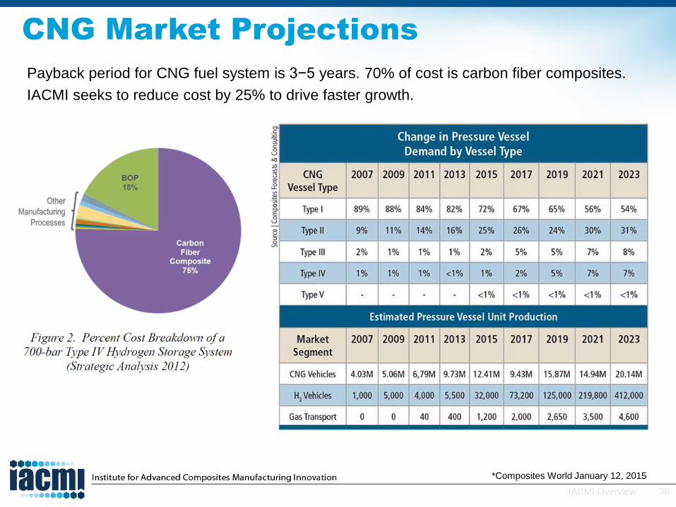
CNG Market Projections
Payback period for CNG fuel system is 3−5 years. 70% of cost is carbon fiber composites.
IACMI seeks to reduce cost by 25% to drive faster growth.

39IACMI Overview
(1) http://www.afdc.energy.gov/vehicles/natural_gas.html(2) overview_of_ngv_cylinder_safety_standards.pdf (Mark Trudgeon, July 2005)
Natural Gas Vehicle Cylinder Safety
Standards
There are approximately 15 million road vehicles, worldwide, using CNG for fuel. That number is increasing every year (but only 150,000 in the US) (1).
In 1992, the US developed ANSI/AGA NGV,2 “American National Standard for Basic Requirements for Compressed Natural Gas Vehicle (NGV) Fuel Containers.” (NGV2-2000) (NGV2-2007) (2)
Cylinder designs that meet the requirements of these standards:
will have a fatigue life that exceeds the specified service life
when pressure-cycled to failure, will leak but not rupture
when subject to hydrostatic burst tests, will have stress ratio factors that exceed the valuesspecified for the cylinder type and the materials used
must meet damage tolerance criteria for drop impact, bonfire, penetration, and environment
Service pressure of 245 bar (3600 psi), safety factor of 2.35 for carbon fiber
IACMI to foster improved safety as well as cost reduction

40IACMI Overview
*Courtesy of Xperion
CGS Manufacture SOA
41IACMI Overview
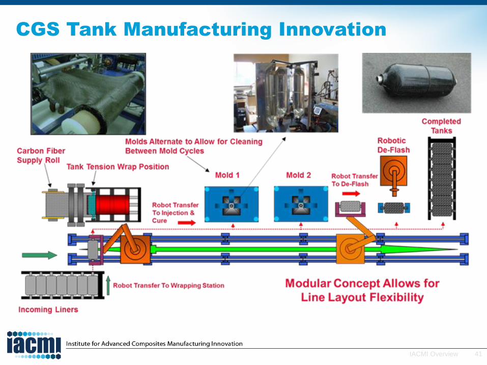
CGS Tank Manufacturing Innovation
42IACMI Overview
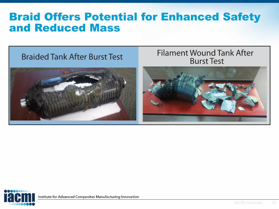
Braid Offers Potential for Enhanced Safety
and Reduced Mass

43IACMI Overview
Safety is Critical
44IACMI Overview
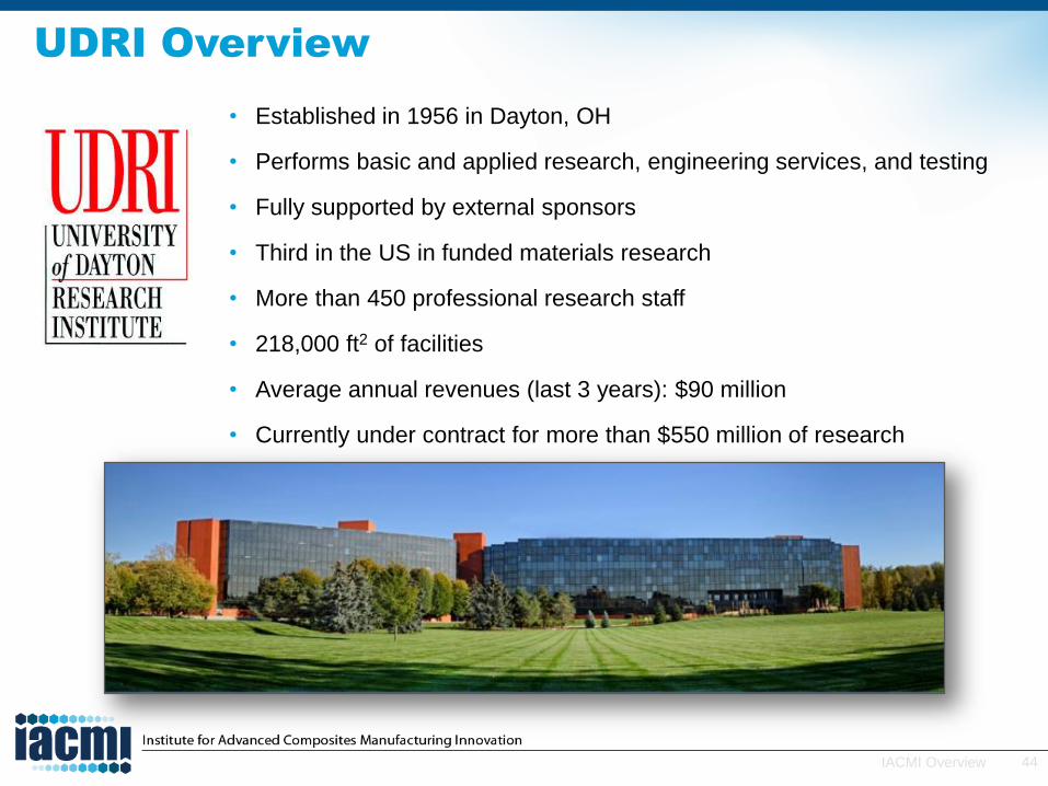
UDRI Overview
• Established in 1956 in Dayton, OH
• Performs basic and applied research, engineering services, and testing
• Fully supported by external sponsors
• Third in the US in funded materials research
• More than 450 professional research staff
• 218,000 ft2 of facilities
• Average annual revenues (last 3 years): $90 million
• Currently under contract for more than $550 million of research

45IACMI Overview
1000 ton press for HP-RTM and prepreg compression molding
Ohio IACMI Automotive Work Cell

46IACMI Overview
Injection Molding Specifications
• Cincinnati Milacron NT440 S Powerline model
• Horizontal injection shot capacity: 40 oz (1135 g)
• Vertical injection shot capacity: 10 oz (284 g)
• Maximum injection rate (horizontal): 20.8 oz/s (590 g/sec)
• Peak injection pressure: 30,000 psi (206 MPa)
Mold and Clamp Unit
• Daylight: 56.1 in. (1425 mm)
• Minimum mold height: 9.8 in. (250 mm)
• Maximum mold height: 29.5 in. (750 mm)
“One of a kind” all-electric Cincinnati
Milacron injection molding machine.
Ability to use 440 tons of clamping
force and two barrels, our machine is
ideal to conduct developmental work
and short production runs for
automotive insert/overmolding
applications.
Dry insert; reinforcing fabric
Thermoplastic Injection Overmolding

47IACMI Overview
Custom Polymer Compounding
Devolatilizing Twin Screw Extruder
• Model: Coperion ZSK 26
• Drive: 30 HP Allen Bradley AC induction motor, 1800 RPM base speed, oil-lubricated reduction and distribution gear assembly with torque limiting coupling
• Screw: co-rotating shafts, 12–1200 RPM screw speed, 82 N-m available torque per shaft, configurable screw designs
• Barrel: 25mm diameter barrels, 1300 mm length, nitrided steel, 7 independent controlled heating zones, 15.6 kW total heating power, 400°C maximum temperature, pressure transducer at barrel exit
• Venting: 3 vent ports for devolatilization, each with vacuum/pressure gauge, sight glass, throttling nitrogen valve, and insert block (when venting is not used). All vents connect to vacuum manifold pipe system

48IACMI Overview
Fatigue testing
of composite
spring
Truck spring fatigue
Structures and Material Evaluation
• Proficient with a large variety of standardized tests(e.g., ASTM, SAE)
− ISO-9000 certification
• Wide variety of materials:
− Metals (e.g., aluminum, titanium, steel, nickel- based, magnesium)
− Composite systems
• polymeric (PMCs)
• metallic (MMCs)
• ceramic (CMCs)
− Elastomers
− Polymers
− Components
− Structures/substructures
49IACMI Overview
Jared Stonecash937-229-4361
Brian Rice937-229-2519
UDRI Contact Information
Contact UDRI personnel to network and discuss potential IACMI projects:

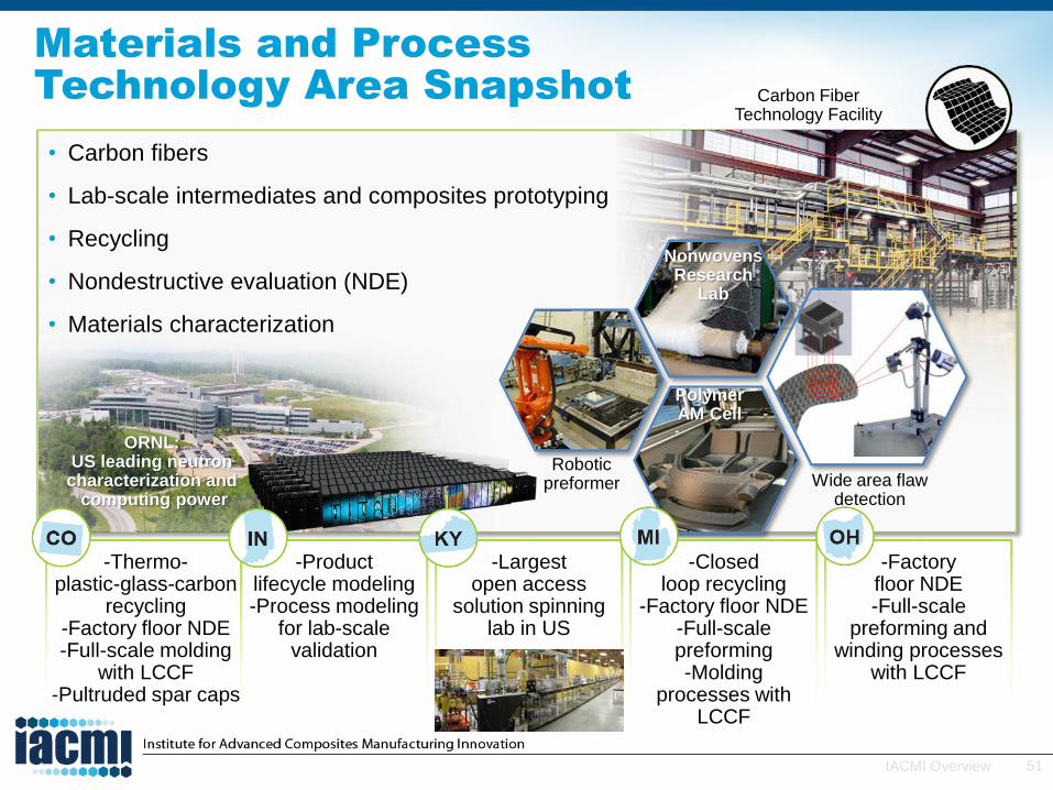
Materials and Processing
Technology Area
Cliff Eberle
Director, Materials and Processing Technology Area
51IACMI Overview
• Carbon fibers
• Lab-scale intermediates and composites prototyping
• Recycling
• Nondestructive evaluation (NDE)
• Materials characterization
Materials and Process
Technology Area Snapshot
Wide area flaw detection
Carbon Fiber Technology Facility
Polymer AM Cell
Robotic preformer
Nonwovens Research
Lab
ORNL: US leading neutron characterization and
computing power
-Thermo-plastic-glass-carbon
recycling -Factory floor NDE-Full-scale molding
with LCCF -Pultruded spar caps
-Product lifecycle modeling-Process modeling
for lab-scale validation
-Largest open access
solution spinning lab in US
-Closed loop recycling
-Factory floor NDE -Full-scale preforming-Molding
processes with LCCF
-Factory floor NDE -Full-scale
preforming and winding processes
with LCCF

52IACMI Overview
IACMI Goals as stated in the Funding
Opportunity Announcement
Focus Areas
• Vehicles• Wind Turbine Blades• Compressed Gas Storage (CNG, Hydrogen)
Five Year Technical Goals
• 25% lower CFRP cost• 50% reduction in CFRP embodied energy • 80% composite recyclability into useful products
Impact Goals
• Enhanced energy productivity• Reduced life cycle energy consumption• Increased domestic production capacity
• Job growth and economic development
TRL 4 - 7
These goals depend on materials and processing technology developments
53IACMI Overview
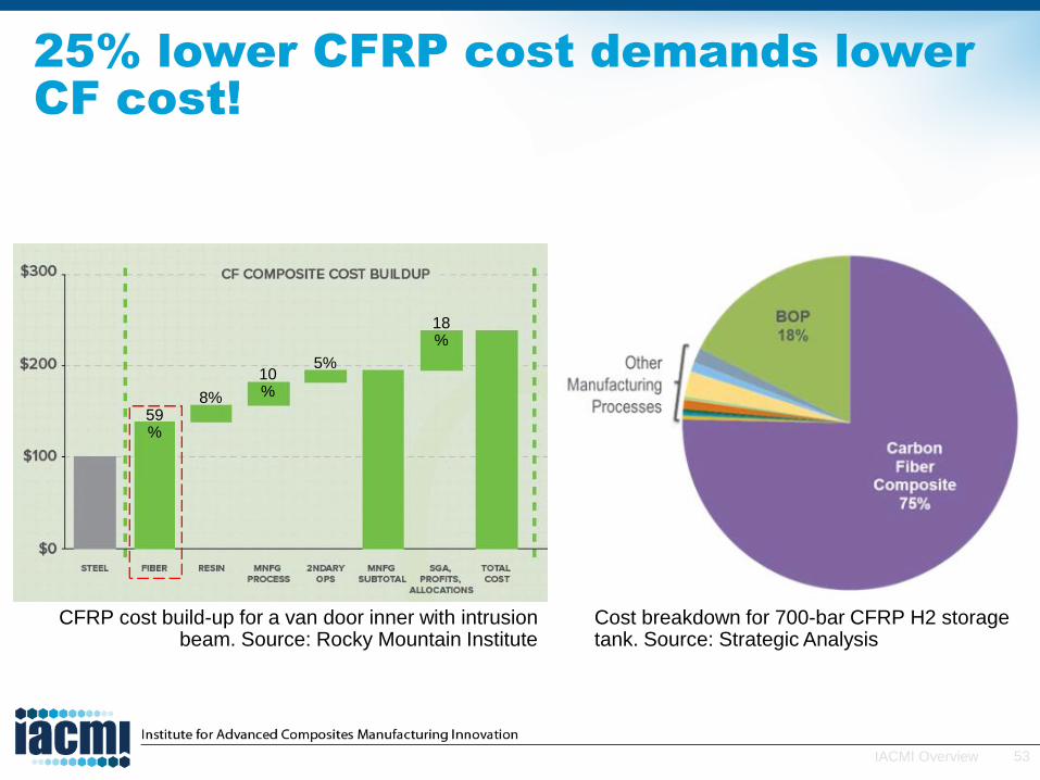
25% lower CFRP cost demands lower
CF cost!
CFRP cost build-up for a van door inner with intrusion beam. Source: Rocky Mountain Institute
Cost breakdown for 700-bar CFRP H2 storage tank. Source: Strategic Analysis
59%
8%
10%
5%
18%
54IACMI Overview
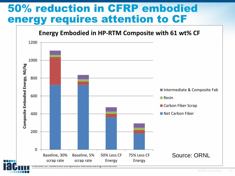
50% reduction in CFRP embodied
energy requires attention to CF
0
200
400
600
800
1000
1200
Baseline, 30%scrap rate
Baseline, 5%scrap rate
50% Less CFEnergy
75% Less CFEnergy
Co
mp
osi
te E
mb
od
ied
En
erg
y, M
J/kg
Energy Embodied in HP-RTM Composite with 61 wt% CF
Intermediate & Composite Fab
Resin
Carbon Fiber Scrap
Net Carbon Fiber
Source: ORNL

55IACMI Overview
IACMI has unique precursor and carbon
fiber processing capabilities
Melt spinning
World’s largest university-based
solution spinning lab
Bench and pilot
scale heat treatment
equipment
World’s most flexible carbon fiber
semi-production facility

56IACMI Overview
Highlighted M&P Composites Fabrication
• Lab scale
– Compounding
– Weaving
– Prepregging
– Injection molding
– Compression molding
– Thermoforming
• Full scale
– Robotic preforming
– 3D printing
– Filament winding
– Pultrusion
Robotic preforming
Big area additive manufacturing cell
57IACMI Overview
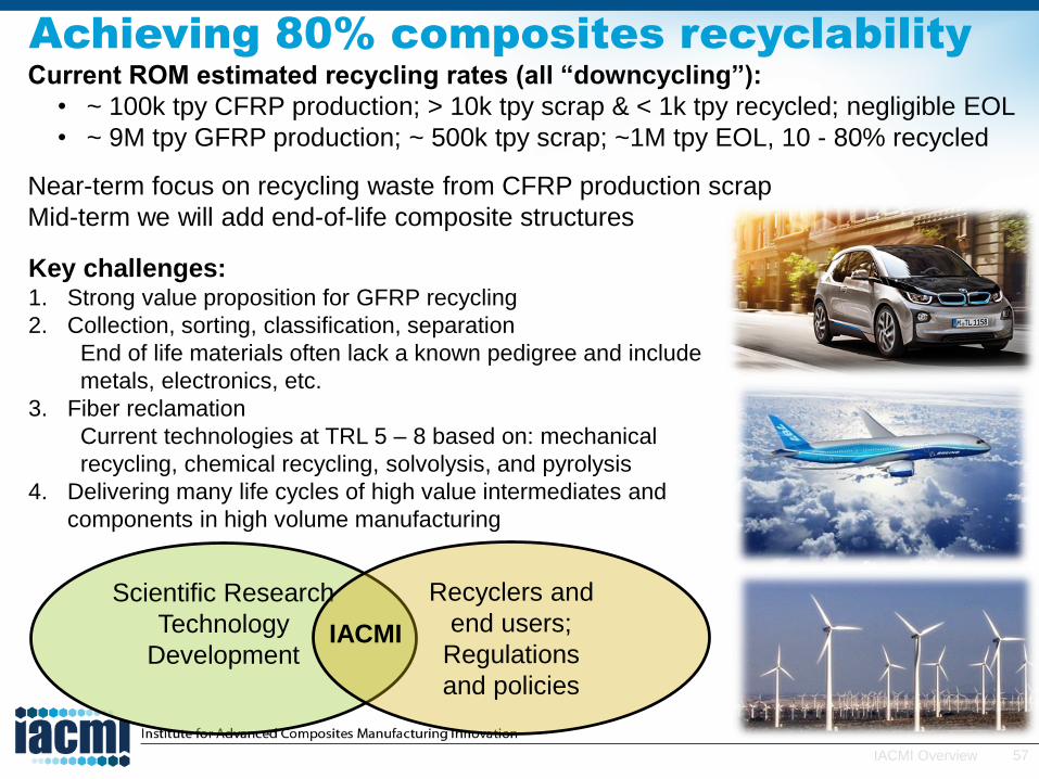
Current ROM estimated recycling rates (all “downcycling”):
• ~ 100k tpy CFRP production; > 10k tpy scrap & < 1k tpy recycled; negligible EOL
• ~ 9M tpy GFRP production; ~ 500k tpy scrap; ~1M tpy EOL, 10 - 80% recycled
Near-term focus on recycling waste from CFRP production scrap
Mid-term we will add end-of-life composite structures
Achieving 80% composites recyclability
Key challenges:1. Strong value proposition for GFRP recycling
2. Collection, sorting, classification, separation
End of life materials often lack a known pedigree and include
metals, electronics, etc.
3. Fiber reclamation
Current technologies at TRL 5 – 8 based on: mechanical
recycling, chemical recycling, solvolysis, and pyrolysis
4. Delivering many life cycles of high value intermediates and
components in high volume manufacturing
Scientific Research
Technology
Development
Recyclers and
end users;
Regulations
and policies
IACMI

58IACMI Overview
IACMI recycling capabilities
Adherent Technologies wet chemical composite recycling pilot reactor
MIT-RCF’s slurry preforming (top) and roll goods (bottom) production in its commercial carbon fiber recycling facility
Photos courtesy of Adherent Technologies and MIT-RCF

59IACMI Overview
Title: Three Dimensional Microstructure of Polymeric Composite Materials Used
in Sandwich Structures Using Dual Modality from Combined High Resolution
X-ray and Neutron TomographyDr. Dayakar Penumadu, University of Tennessee, Knoxville, USA
18th International conference on Composite Materials (ICCM 18), Jeju, S. Korea
Navy Relevance: Understanding the failure mechanism at multi-length scales non-destructively of the wet and dry CFRP specimen will benefit
with safer application of CFRP use in Navy vessels.
Current Research: X-ray and neutron tomography techniques provide non-destructive method to visualize the interior of the CFRP facings for
failure mechanism investigation. The technique revealed the non-uniform density distribution of resin in the sample. The wet sample failed with
the delamination of the outer layer concentrating in the failure zone while the entire dry sample took part in the failure process during cyclic
loading.
Objective: Overview of X-ray and neutron tomography performed on the CFRP facing used for sandwich structures is given. The capabilities and limitations of the techniques are presented. Three-dimensional Image registration of X-ray and neutron tomography data is performed, and the contrasts of X-ray and neutron images are compared. The imaging technique will be applied to study the failure mechanism of wet and dry CFRP under loading.
X-ray Tomography SetupNeutron Tomography Setup
Peak Energy: 7.30x10⁻⁶ keV
Parallel Beam
Resolution: 29.8 m/voxel
FOV: 61 x 61 mm2
Peak Energy: 100 keV
Cone Beam
Resolution: 13.2 m/voxel
FOV: 30.5 x 30.5 mm2
Neutron Tomography Slice X-ray Tomography Slice
Dry Wet
Failure
ZoneAway Failure
ZoneAway
Failure Mechanism Comparison of Wet and
Dry CFRP after Cyclic Loading
1.70
cm-1
0.98
0.27
Resin
Fiber Bundle
Non-Uniform Resin
Density Distribution
NDE Overview
• We apply NDE data to help meet IACMI metrics for speed and yield by closing the loop around process design and control.
• We deploy our NDE capabilities where and when needed across the supply chain and product lifecycle.
Process Quality ControlProperty Quality AssuranceProduct Lifecycle Support
Flaw imaging
Precursors
Fibers
Composites
Components
Assemblies
Rapid inspection
Process monitoring
of material state
Products
Health
monitoring
Microstructure
imaging
60IACMI Overview
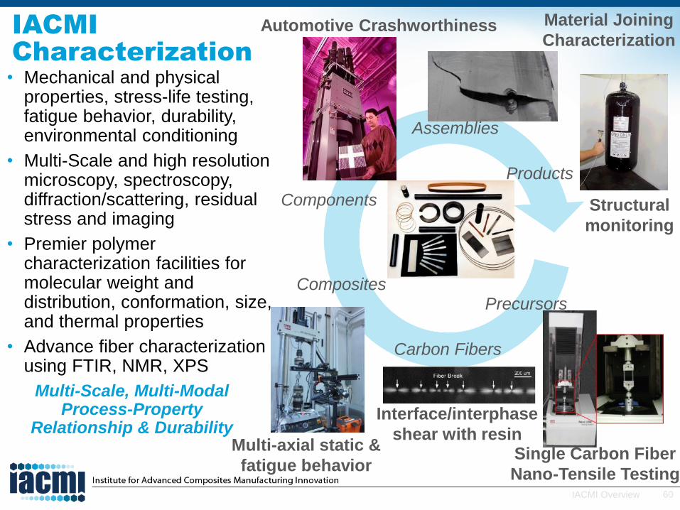
IACMI
Characterization
• Mechanical and physical properties, stress-life testing, fatigue behavior, durability, environmental conditioning
• Multi-Scale and high resolution microscopy, spectroscopy, diffraction/scattering, residual stress and imaging
• Premier polymer characterization facilities for molecular weight and distribution, conformation, size, and thermal properties
• Advance fiber characterization using FTIR, NMR, XPS
Multi-Scale, Multi-ModalProcess-Property
Relationship & Durability
Automotive Crashworthiness
Precursors
Carbon Fibers
Composites
Components
Assemblies
Products
Structural
monitoring
Multi-axial static &
fatigue behaviorSingle Carbon Fiber
Nano-Tensile Testing
Interface/interphase
shear with resin
Material Joining
Characterization

61IACMI Overview
Materials and Processing POC’s
Doug Adams (NDE)
615-322.-2697
Cliff Eberle (M&P)
865-574-0302
Soydan Ozcan (Recycling)
865-241-2158
Dayakar Penumadu
Materials characterization
865-974-2503
Matt Weisenberger
Solution Spinning
859-257-0322

Innovative Modeling and
Simulation Technology Area
R. Byron PipesExecutive Director
Innovative Modeling and Simulation Technical Area
63IACMI Overview
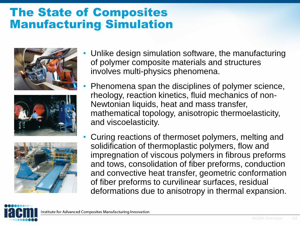
The State of Composites
Manufacturing Simulation
• Unlike design simulation software, the manufacturing of polymer composite materials and structures involves multi-physics phenomena.
• Phenomena span the disciplines of polymer science, rheology, reaction kinetics, fluid mechanics of non-Newtonian liquids, heat and mass transfer, mathematical topology, anisotropic thermoelasticity, and viscoelasticity.
• Curing reactions of thermoset polymers, melting and solidification of thermoplastic polymers, flow and impregnation of viscous polymers in fibrous preforms and tows, consolidation of fiber preforms, conduction and convective heat transfer, geometric conformation of fiber preforms to curvilinear surfaces, residual deformations due to anisotropy in thermal expansion.
64IACMI Overview
Human Talent and Tools
• Education and training of a new generation of engineers who can transform a metals-based industry to a composites-based industry is needed.
• Simulation tools that capture the multiplephenomena in composites manufacturing to achieve near-optimum manufacturing and designs are essential.
• These tools can revolutionize high performance products for energy efficiency and value in use.

65IACMI Overview
• Purdue’s cdmHUB and cvfHUB will put browser-based simulation in the hands of subject matter expertsand Tier III suppliers− cvfHUB: Deliver a comprehensive suite of commercial simulation
tools for center of excellence project teams in MI, OH, CO, TN
Innovative Design, Predictive Modeling
and Simulation Technology Area: Portal IN
Integration of many major commercial simulation tools
Vehicle teams
Wind teams
CGS teams
Tool training
Tool evaluator (TML)
New tool development
Commercial tools
Browser-based
Secure data
• Automated tape laying and fiber placement
• RTM• Nondestructive
evaluation• Curing simulation
• Molecular material studies
• Material and discovery studio
• Preforming draping • Simulation cure kinetic
modeling
• HP-RTM• Preforming• Joining• Braiding• Design and modeling
simulation• Draping simulation• Curing
• Molecular material studies
• Material and discovery studio

66IACMI Overview
Preform
Stacking
Consolidation/
Compaction in
Mold
Consolidated Preform Assembly: Fiber Orientation
Cure Kinetics in
the Mold
Heat Transfer
and Exotherm
in the Press
Resin Infusion
Effective Anisotropic Heat Transfer Properties
Preform Assembly: Fiber Orientation
Residual Stress
State
Preform
Shaping
Effective
Mechanical
Properties
Post-mold
Deformation
CATIA
DIGIMATPAM-RTMDIGIMAT
CATIA DIGIMATCATIA
RAVEN
CATIA/COMPAC
DIGIMAT COMPRO MARC/ ABAQUS
COMPRO
Model Composites Manufacturing
Process—High Pressure RTM
67IACMI Overview
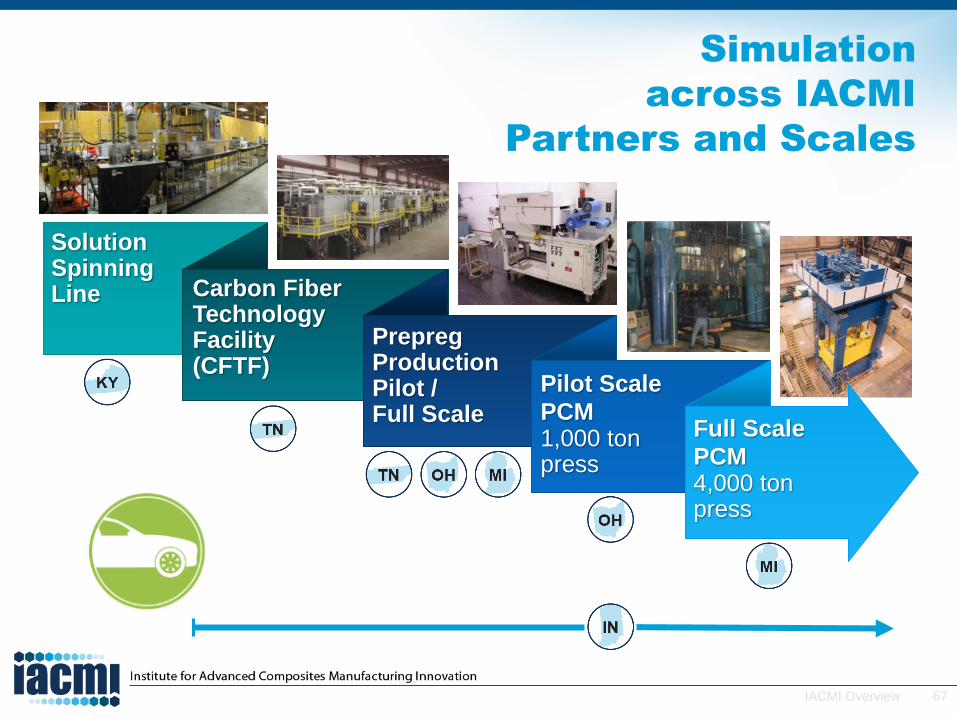
Simulation
across IACMI
Partners and Scales
SolutionSpinningLine Carbon Fiber
Technology Facility (CFTF)
Pilot Scale
PCM1,000 ton press
PrepregProductionPilot / Full Scale
Full Scale
PCM4,000 ton press
68IACMI Overview
Simulation Tool Validation
• Simulation tools validated at the lab scale at Purdue
• Lab-scale manufacturing process facilities established for all IACMI processes
• Simulation tools validated for all manufacturing processes within IACMI
• Simulation tool input data developed for all IACMI materials systems and processes
• Simulation tool validated at subscale and full scale at other IACMI sites

69IACMI Overview
Indiana Manufacturing Institute
70IACMI Overview
Indiana Manufacturing Institute (IMI)
• WEST LAFAYETTE, Ind.—Purdue Research Foundation board of directors on February 18, 2015 approved construction of the $50 million, 62,000 ft2 IMI, where Purdue University researchers will expand research in composite materials manufacturing.
• IACMI will occupy approximately 30,000 ft2 of the IMI.
• Validation at the lab scale for all IACMI manufacturing processes will be located adjacent to simulation studios of the cvfHUB.
• Cooperating industries are invited to co-locate in the IMI.

71IACMI Overview
Innovative Design, Predictive Modeling
and Simulation Technology Area: Portal IN
• R. Byron Pipes, Executive Director [email protected](765) 418-5447
• Ron Steuterman, Managing Director [email protected](765) 426-1335
• Wenbin Yu, cvfHUB Director [email protected](435) 764-8877
• Johnathan Goodsell, Validation Director [email protected] (765) 414-7858
WE WELCOME INQUIRIES

Working with IACMI
Craig Blue
Chief Executive Officer
73IACMI Overview
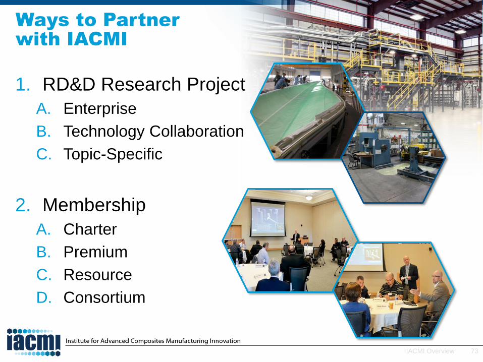
Ways to Partner
with IACMI
1. RD&D Research Project
A. Enterprise
B. Technology Collaboration
C. Topic-Specific
2. Membership
A. Charter
B. Premium
C. Resource
D. Consortium
74IACMI Overview
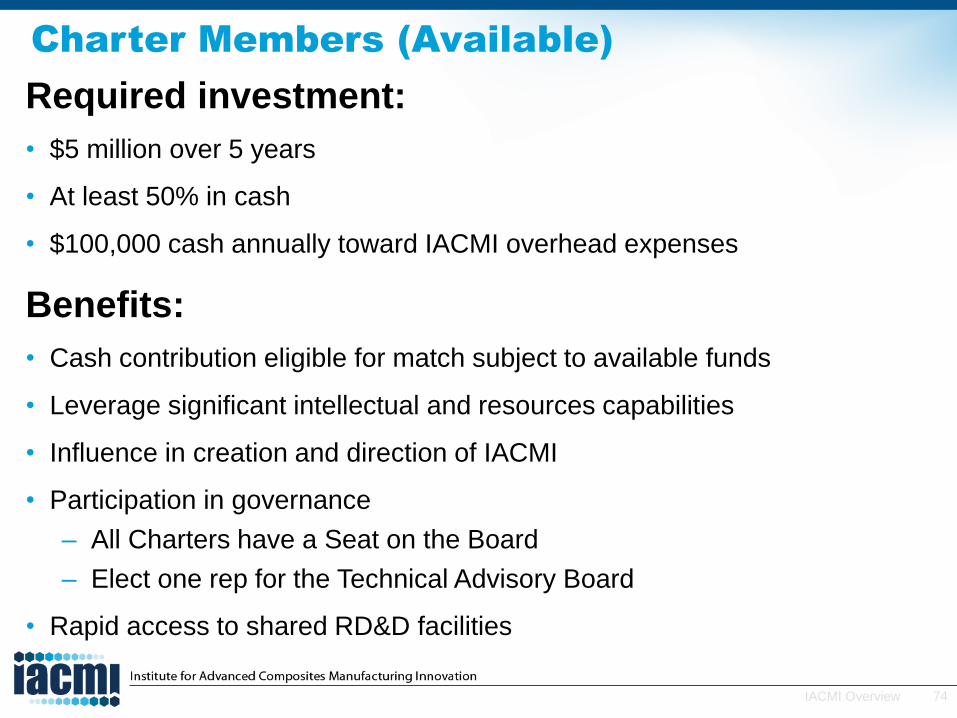
Charter Members (Available)
Required investment:
• $5 million over 5 years
• At least 50% in cash
• $100,000 cash annually toward IACMI overhead expenses
Benefits:
• Cash contribution eligible for match subject to available funds
• Leverage significant intellectual and resources capabilities
• Influence in creation and direction of IACMI
• Participation in governance
– All Charters have a Seat on the Board
– Elect one rep for the Technical Advisory Board
• Rapid access to shared RD&D facilities

75IACMI Overview
Premium Members (Available)
Required investment:
• $1 million over 5 years
• At least 50% in cash
• $20,000 annually toward IACMI overhead expenses
Benefits:
• Cash contribution eligible for match subject to available funds
• Participation in governance
– Elect one rep for the Board
– Elect one rep for the Technical Advisory Board
• Leverage significant intellectual and resources capabilities
• Enterprise-wide proprietary projects
76IACMI Overview
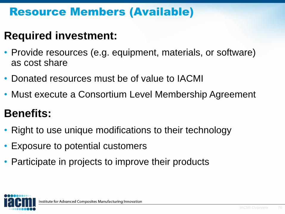
Resource Members (Available)
Required investment:
• Provide resources (e.g. equipment, materials, or software) as cost share
• Donated resources must be of value to IACMI
• Must execute a Consortium Level Membership Agreement
Benefits:
• Right to use unique modifications to their technology
• Exposure to potential customers
• Participate in projects to improve their products

77IACMI Overview
Consortium Members (Available)
Required investment:
• $5,000 annually for industry with ≤500 employees and educational institutions
• $10,000 annually for industry with >500 employees
Benefits:
• Opportunities to engage
• Opportunities to build key relationships
• Opportunities to participate in governance
– Elect one SME rep for the Board
– Elect one SME and one Large Co. rep for the Technical Advisory Board
• Opportunities to fuel your company’s growth within the composites ecosystem
78IACMI Overview
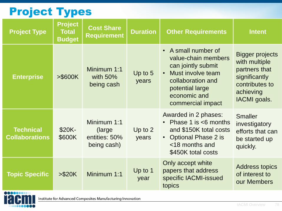
Project Types
Project Type
Project
Total
Budget
Cost Share
RequirementDuration Other Requirements Intent
Enterprise >$600K
Minimum 1:1
with 50%
being cash
Up to 5
years
• A small number of
value-chain members
can jointly submit
• Must involve team
collaboration and
potential large
economic and
commercial impact
Bigger projects
with multiple
partners that
significantly
contributes to
achieving
IACMI goals.
Technical
Collaborations
$20K-
$600K
Minimum 1:1
(large
entities: 50%
being cash)
Up to 2
years
Awarded in 2 phases:
• Phase 1 is <6 months
and $150K total costs
• Optional Phase 2 is
<18 months and
$450K total costs
Smaller
investigatory
efforts that can
be started up
quickly.
Topic Specific >$20K Minimum 1:1Up to 1
year
Only accept white
papers that address
specific IACMI-issued
topics
Address topics
of interest to
our Members

79IACMI Overview
IP Summary
Enterprise and
Technology
Collaboration
Projects
Topic Specific
Projects
Company(ies)
Generated IP
Company(ies) owns* 1st: Charter Members would get a
6 months from notification option to
co-exclusive commercial license* then;
2nd: Premium Members would get a
6 months from notification option to
co-exclusive commercial license* then;
3rd: Resource Members would get a
6 months from notification option to
co-exclusive commercial license*.
Academic & DOE
National Lab
Generated IP
Company(ies) would get
6 months option to a
field-limited exclusive
license for an additional
fee*
Jointly-Created IP Same as above*
*Government agencies may have certain statutory or contractual IP rights, e.g. license for government use,
requirements, and substantial US Manufacturing

80IACMI Overview
Project
Proposal
and Review
Process
RFP will include
evaluation criteria,
including statement
of industrial need that
aligns with IACMI
goals
Responsive to
roadmap needs
Evaluators include
Directors, TAB, TAB-
assigned, BOD,
and/or DOE
White Papers
accepted on a rolling
basis

81IACMI Overview
$70M - DOE
$189M - Other
123 - Member Consortium
6 Core Partner States
Strong Leadership
5 Technology Areas
Production capacity
Jobs
- 75%CFRP embodied energy savings
- 50%CFRPproduction cost
Greenhouse gas avoidance
- 25%
- 50%
- 50%- 75%
95%FRP recycled and/or reused
80%
Federal Investment Will Catalyze
a Composites Ecosystem in the
Heart of US Manufacturing

82IACMI Overview
Questions?
• Visit IACMI.orgto learn more.