i three cardinal -.-.------------------. ..,. , ..:..z€¦ · this meter, which is of the moving...
TRANSCRIPT

CONSOLE INSTALLATION IMPROVEMENTSi
DECEMBER 7th 1929 15 CENTS Threeof
Cardinala Receiver
Virtues-.-.------------------.
E ,--------- A. I N.1 ty. I s 4 -.1 ,z -4-s i -..-4 ,
.t: '.*4*: I
. ------,... -..,........,. ,_..:..z.1. 1 --- i1
-......- -4....
1 1
,.:... .....r. ,..... 4
...,....,_,...i e A
,...vt.
4:..,.
4" ,' Voltage DivisionREG. U.S. PAT. OFF.
... .._--7.,...--,S"'
Push-Pull Speakerst"..----.'.4 4......",.. :::..t .. %..? p.,-ttv:4:111 )110)
...,.: ..,1 . ::,..., ,v......
---------.
..,--.-...........
,.".--7.1
.r1
r...'-'...ss'.- -.*.."''''s---.\ ...s.____...,.._,...
... ,.. .... ......
. ,...
4' .. A- A-7Z 7_,..:.*--t. -- --- 4-4" 4 ?...0
__.......,-..--- HowTold
Currentfor Schoolboys
Flows402nd Consecutive Issue-EIGHTH YEAR
e
1
f
1,X
ie.lir
... .
< .
L
AllibwilimP
),. ClIall 4 .6g0 .41.
. 44P
."411Orws
--
' Coils are tested for identical inductance by means of an oscillator. When zero beat isestablished the coil under test is just the same inductance as the master model. See
article on pages 5, 6 and 7.
RADIO WORLD, published by Hennessy Radio Publications Corporation. Roland Burke Hennessy, editor; Herman Bernard, managing editor and business manager,all of 145 West 45th Street, New York, N. Y.

RADIO WORLD December 7, 1929
NEW J -245-X TROUBLE -SHOOTING JIFFY TESTERIllumination Continuity and Polarity
The three -meter assembly, In the crackle -brown finish carrying case, with slip-oncover in place. The handle is genuineleather. The buckled strap holds the
cover on.
Makes All Necessary Tests inTHE new Jiffy Tester, J -295-X, is a complete servicing outfit. It
consists of a three -meter assembly in a metal case, with slip-oncover and a cable plug. There are ten adapters. It is vital to
have the complete outfit so you can meet any emergency.With this outfit you plug the cable into a vacated socket of a receiver,
fort makingremoved
te stusb: e pinla tethe urterestnetr,
uapn
dou
si1n0gthe llraemcepiveerre'ss; plate
voltage up to 300 volts; filament or heater voltage (AC or DC), upto 10 voila.
Each meter may be used independently. One of the adapters-a pairof test leads, one red, the other black, with tip Jack terminals-serves
this purpose. Multiplier J-106 extends the range of the DC voltmeterto 600 volts, but this reading must be obtained independently, as must
readings on the 0-60 scale of the DC voltmeter. Independent readingof the AC voltmeter for line of voltage is necessary; also to use 0-190scale while Multiplier J-111 extends the AC scale to 560 volts for readingpower transformer secondaries.
The other adapters permit the testing of special receiver tubes, so that
tests may be made, in all, of 22 different tubes: 201A, 200A.
TJX199, TriT199, 120. 240. 171, 171A. 112. 112A. 245. 224, 222, 228.
280, 281, 227, 226, 210. 250, Kellogg tubes and old style Arcturus tubes.
iwwrs __ to WO Mr. WO WI%
GUARANTY RADIO GOODS CO.143 West 45th Street, Just East of Broadway.N. Y. City.171 Please send me on 5 -day money -back guaranty your J -295-X Jiffy
Tester, complete, with all 10 adapters, and with illuminated TesterFREE with each order. Also send instruction sheet, tube data sheet
and rectifier tube testing information.CI Enclosed pleasend 315.82 remittance. Ship at your expense. [Canadian
must be P.O. or ExpressCI Please ship C. 0. D. $15.82 plus cartage and P.O. fee.
NAMEADDRESS
CITY STATE
S -DAY MONEY -BACK GUARANTY
Tester FREE with Each Outfit!
Your Price
$ 1 5.82Complete
Illumination Tester, VestPocket Size, Shows Shortsand Opens Visually, alsopolarity of DC line. A
Neon lamp is built In.
1-1 I I Multiplier, upper left, with tip; below it. J-106 Multiplier with tip; plugs, eft toright, J -I9, conforms UV socket to UX plug; 1-20, conforms UX tester socket toUVI99 tube; J-24, to test Kellogg and ola style Arcturus tubes.
a Jiffy and Simplifies Service Work!HEN servicing a radio set, power amplifier, speech amplifier or soundreproduction or recording eouipment, the circuits and voltages are almostinaccessible, unless a plug-in tester is used,
The Jiffy 245-X plugs in and does everything you want done. It consists of:(1)-The encased three -meter assembly, with 4 -prong (UX) and 5 -prong
(UY) sockets built in; changeover switch built in, from 0.20 to 0-100 ma.;ten vari-colored jacks, five of them to receive the vari-colored tipped ends ofthe plug cable; grid push_button, that when pushed in connects grid directto the cathode for 224 and 227 tubes, to note change in plate current, and thusshorts the signal input.
(2) -4 -prong adapter for 5 -prong plug of cable.(3)-Screen grid cable for testing screen grid tubes.(4)-Pair of Test Leads for individual use of meters.(5)-J-106 Multiplier, to make 0-300 DC read 0-600.(6)-J-111 Multiplier, to make 0-140 AC read 0.560.(7)-Two jack tips to facilitate connection of multipliers to jacks in tester.(8), (9), (10)-Three adapters so UV199 and Kellogg tubes may be tested.(11)-Illumination Tester.The illumination tester will disclose continuities and opens and also the
polarity of DC house mains. It is as handy as a pencil and fits in your vestpocket. It works on voltages from 100 to 400. There are two electrodes in aNeon lamp in the top of the instrument. On AC both electrodes light. OnDC only one lights, and that one is negative of the line, the light being onthe same side as the lead. Hence the illuminator shows whether tested sourceis AC or DC, and if DC, which side is negative.
Even the output of the speaker cord will show a light.Also, the device will test which fuses are blown in fused house lines, AC orDC. Besides it tests ignition of spark plugs of automobiles, boats and airplanes,
also faulty or weak spark plugs.Just flash on the illumination tester momentarily. It will last about 4,000
flashes.
W

December 7, 1929 RADIO WORLD 3
0-600v, AC & DCHigh Resistance Meter
ACCURATE TO 1%!
0-800 AC and DC Voltmeter-oeme meter reads heti-with 82" long flexible corda built in, and equippedwith hanger. Extreme diameter (less hanger) 2%".
MOST USEFUL!Here is a meter that nerves an abundance of rues.
because it has a wide voltage range, 0 to 600 volts, andmeasures voltage of alternating current and direct current,and is accurate U 1%. In meter it's accuracy thatcounts.
You can measure not only the DC voltages of Beliminators, power packs and B batteries, with easilylegible readings of 20 volts per division of the Neale,with wide division' between 100 and 400 volts, to theYOU can easily see to within 5 volts, but you can alesmeasure the AC voltage across high -voltage power transformer seconderiee If full -wave rectification Is used,you measure each of the two sections of the transformersecondary and add the renege". Thus up to 1,200 totalvolts across the secondary may be read. For half -warerectification. a secondary up to 600 volts is read acrossthe total winding. You find out at once whether thiswinding is open or "honed, since no reading then wouldbe obtained, or find out whether the voltage is right.or too high or too low. In all instances the AC voltageacross the secondary should read higher than the de-sired DC output, due to the voltage drop In the tubeand to the current in the entire voltage divider and itssections. The normal deduction from the AC voltage, toobtain the DC voltage, is at leant 10%.
A REQUISITE FOR SERVICING!Often 'mice men, experimenters and students 0311.1
know not only the transformer high voltage. but alsowhether the AC line voltage is the rated 110 volts or notThis meter tells you. Connect it across the 110 -volt lineBy reading this voltage and the voltage of the high-voltagesecondary you can also determine the etep-up ratio, bydividing the smaller reading into .the larger.
Because this is a high -resistance meter YOU can relyon the accuracy of the readings.
Only a high -resistance meter can accurately measurethe DC voltage of a B eliminator. Other meters draw somuch current that the reading may be 50 volts leo.than what it should be, or still more inaccurate, andyou could almost guess the voltage more accurately theea low -resistance meter would read.
MONEY -BACK GUARANTY!Thin meter 1s Bold on a 5 -day money -back guaranty.
Buy one, try it, test it thoroughly, compare It with othermeters in performance and appearance. If not fullysatiofied, send it back and your money will be promptlyrefunded.
The meter is full nickel plated, highest possiblepolish, has green cords, with red ( positive) and black(negative) moulded bakelite tip -holders, and sturdy tips.
The positive and negative Indications are for DC measure-ments. For AC the meter may be connected at random.
This meter, which is of the moving vane type. lemade in Germany and represents finest workmanship.Cat. M600 AC -DC $4.95
SEND NO MONEY!
GUAR. NTY RADIO GOODS COMPANY,149 West 45th Street, New Yerk, N. Y
(Just East of Broadway).Please ship at once C.O.D. one 0-800 voltmeter, read
log both AC and DC, on 5 -day money -back guaranty.This meter must be exactly as advertised in Radio WorldCat. M600, price $4.95
NAME
ADDRESS
City State
5 -DAY MONEY -BACK GUARANTY
New
Farrand InductorExtremely Sensitive, Faithful Speaker at 50% off List Price!
Model 6-G . $10.00List Price $20.00
Model 10-G . . $11.00List Price $22.00
The New Farrand Inductor Chassis, the Inductor unit on a spider astern bly, with gone and supporting brackets. Chassis comes completely assem-bled, with 10 -ft. cord, ready to play.
How the New Inductor Excels!THE new Farrand Inductor Chassis is all the rage now because it affords
extremely high sensitivity with faithful reproduction of all the notes ofthe audible scale. Here is a speaker that will support the good low -note
reproduction of the most modern and most excellent audio amplifiers, withoutdiscriminating against middle or upper frequencies. If you do not have aspeaker that will respond faithfully to the audible scale of frequencies, then thevalue of any good audio amplifier is largely lost.
An entirely new principle is involved in the Inductor Unit. The armature,instead of moving from side to side in the direction of the pole pieces, as hap-pens in ordinary magnetic units, moves like a piston along the length of theair gap and maintains a steady distance from the pole pieces. As the sensi-tivity is extraordinarily high, the gap is made wide, and the armature will notstrike the pole pieces.
The Inductor Chassis comes completely assembled, ready for operation. Allyou need do is connect the speaker cords to the output posts of your receiveror power amplifier. No energizing field is necessary.
Treat yourself to one of these exceptional chasses, and put it in a cabinet,or use some other form of baffle if you prefer. The chassis works well justas you get it, but works still better when aided by a cabinet or baffle.
These models, No. 6-G and No. 10-G, work exceptionally well with any of thefollowing as single output tube: 171, 171A, 245 or 250. Also the same modelsare meant for any type of tubes in push-pull.
Model No. 6-G is 10" extreme outside diameter of cone, and Model 10-G is12" extreme outside diameter of cone. The larger size, Model 10-G, gives a littlebetter reproduction of low notes. Both types stand the same exceedingly highvolume and output and use exactly the same unit.
Brookfield CabinetModel 10 for 10-G Inductor
Model 6 for 6-G InductorEither cabinet $6.50
A highly suitablecabinet for the Far -rand InductorChassis is theBrookfield, made intwo models, one foreach size Inductorcone. The finish isgenuine ply wal-nut. The baffle et -f ect is particularlyfine. These cabinetsare specially madefor these speakersand are beautiful inappearance, as wellas sturdy, becauseof extreme expert-ness and care inmanufacture.
Acoustical Engineering Associates143 West 45th Straet, New York City.
(Just East of Broadway)Ge.itlemen : Enclescd please find 0 money order
0 check for $ for which pleasesend me at once
0 One Model 6-0 Farrand Inductor SpeakerChassis, $10.000 One Model 10-0 Farrand Inductor SpeakerChassis, 11.000 One Model 10 Brookfield cabinet 6.500 One Model 6 Brookfield cabinet 6.50
0 For C. 0. D. shipment pot cross here
Name
Address
City State[Prepaid orders shipped same day as received
Canadian remittance must be by postal or ex-oress money order.]

4 RADIO WORLD December 7, 1929
111aveYouSeen the NE,RADI 0IV IE
inmdg News..
RADIO NEWS
The NEW RADIO NEWS,Dept. 8601,
881 Fourth Avenue, New York, N. Y.
Gentlemen:Please send me the next 9 Issues
of the NEW RADIO NEWS ab yourspecial introductory offer of only $1,which I enclose (regular newsstandprice is $2.25 for 9 issues, or $2.50 a year by subscription). 1
understand that you will cheerfully return my dollar if I am notperfectly satisfied after reading the first issue.
Name
City
Address
-0-0
I
I
I
I
I
I
I
I
I
-I
CCASIONALLY a man gets so close toradio that he doesn't see the broaderaspects of the industry. Certainly it isall right to know about the newest re-
ceivers, and how to build them. Certainly thenewest discoveries in servicing and handlingradio parts and sets should be told clearly andat length in the magazine he reads. The NEWRADIO NEWS brings you all this every month.
But it brings you much more than this. Itprovides you with the vital radio news of thewhole world in a terse, business -like way thatdemands reading by every man whose interestlies in radio.
Beyond the fact that the NEW RADIONEWS is actually new from cover to cover, youbegin to realize that RADIO NEWS hasgrown up.
It sees with modern vision the trends and de-velopments in the radio industry. If a new dis-covery in television occurs in Greece or evenPatagonia, you'll find all you want to knowabout it in the NEW RADIO NEWS. If theFederal Radio Commission makes some new rul-ing, you can count on RADIO NEWS for thecomplete story of it. If an Austrian inventordesigns a new improved radio tube, you'll besure to find it all explained in RADIO NEWS.
That is why we say with emphasis-if it'sradio news, it is in RADIO NEWS. And if youare the sort of man whose mind seeks an ex-ecutive viewpoint of radio's rapid progress,you'll want the NEW RADIO NEWS deliveredto you every month.
A SPECIAL OFFERTO RADIO MEN
To introduce the NEW RADIO NEWS tothose in the industry, we offer to send you thenext 9 Big Numbers for a single $1! On thenewsstands you would have to pay $2.25 forthese same 9 issues, or $2.50 a year by sub-scription. We make this exceedingly low offer,because we know that once you see the NEWRADIO NEWS, you will continue to read it inthe years to come.
Simply fill out and mail the coupon at theleft. It brings you the Big New RADIO NEWSat a jobber's discount.

0I 1, 1111,1,116$ la NI o11111111111111111101111111111111,11 ,I11111,1i111 1,1.1.,11111,0,111I
r.r;i 04: ittypT -`11,-.
Ali- ..... ,.0 .
, I7
61
AFfriliili11111.zz.U1,44-74Att,
47i)ri TIT 11111111'V IiiiiIIIMIT Mill'r
1,1,I
Vol. XVI, No. 12December 7th,
15c per Copy, $6.00(Entered as second-class1922, at the Post OfficeN. Y., under act of
Whole No. 4021929
per Yearmatter, March,at New York,March, 1879.]
Technical Accuracy Second to NoneLatest Circuits and News
EIGHTH YEAR
A Weekly Paper published by HennessyRadio Publications Corporation, fromPublication Office. 145 West 45th Street,
New York, N. Y.(Just East of Broadway)
Telephone, BRYant 0558 and 0559RADIO WORLD, owned and published by Hennessy Radio Publications Corporation, 145 West 45th Street, New York, N. Y. Roland Burke Hennessy,president and treasurer, 145 West 45th Street, New York, N. Y.; M. B. Hennessy, vice-president, 145 West 45th Street, New York, N. Y.; HermanBernard, secretary, 145 West 45th Street, New York, N. Y. Roland Burke Hennessy, editor; Herman Bernard, business manager and managing editor;J. E. Anderson, technical editor.
Console InstallationsHow Some Common Troubles May Be Avoided
By H. B. HermanCONSOLE installations present some special problems,
one of them being acoustical coupling, another box reson-ance. Also, occasionally the space problem arises, as
apparently one has more apparatus than can be accommodated,and in seeking a way out he will run into stray coupling diffi-culties.
It has been noticed by nearly every experimenter who hasbeen engaged on AC work that hum often arises as if fromsome inexplicable cause. This will happen almost invariablywhen the speaker is in the console, and the power amplifier isclose to it. What is meant by "close" is hard to define exactly,as the degree of amplification in the audio amplifier has muchto do with the consequent trouble.
If the amplification is high, the field about the audio apparatusis strong, hence the same separation that under other circum-stances would be wide and hum -free becomes close and hum -bound. If hum arises the coupling is too close.
TILT OFTEN SOLVES PROBLEMSince the speaker is some form of electro-magnet, changingthe relative position of the speaker in respect to the audio
amplifier often will provide a ready remedy. If the console isso built that the speaker must be in a given position, as isnearly always the case, due to the baffle and cutout for therim of a cone, then if relative alteration of position is to beintroduced, that must be done by tilting the audio amplifier.
A slight tilt often will solve the problem.Another simple remedy, where the power amplifier is inde-pendent of the tuner, is to turn the power amplifier around.
Often the detector tube of the tuner is so positioned that it istoo close to the output of the power amplifier. Of coursecoupling between tuner output and power amplifier input isihtentional, the very means of delivering from one the voltageand current intended for the other. Stray coupling usuallyarises between the detector and the power amplifier output,or the speaker and detector.
By turning the power amplifier around, even at the sacrificeof putting binding posts out of ready reach, the separationbetween unintentionally united circuits may be increased, and apermanent cure effected.
CAPACITY EFFECT ON HUMHum that is due to poor filtration requires better filtration.
If the capacities are too low and the inductances of the choicecoils in the filter section are too low, increase these. To increasecapacity, connect extra capacity in paralled with existingcapacity, but be sure that the condensers newly introduced havea sufficiently high voltage rating for the purpose. Do not usea 200 volt DC voltage rating condenser across a rectifier output,as these days the output voltage DC is more likely to be around400 to 600 volts at that point.
Additional choke coils should be connected in series, prefer-ably at the filter section output.You can have too much capacity, as welt as too little. This
arises from the fact that th- filter is, broadly speaking. a tunedcircuit, tuned to trap out the objectionable frequencies intro-duced by the AC line itself through the power transformer..Therefore if you use too much capacity you may miss the regionof desired exclusion. just as you may do by using too little.This point, important though it is, often is overlooked, and
FIG. 1HOW A DYNAMIC SPEAKER IS PLACED IN A CON-
SOLE SO AS TO USE THE BOTTOM BOARD OF THECONSOLE AS A BAFFLE. PARTICULARLY IN ROOMSTHAT HAVE CARPETED FLOORS THIS METHOD
WORKS OUT EXCELLENTLY.
seldom has been mentioned in print. The author never saw apublished statement on the subject.
POSITIONS OF SPEAKERS
In console installations hum accentuation may be due to boxresonance, which is the characteristic of the box wherebyfrequencies of particular pitch are echoed and thus becomeadditive in their radiation. This accounts largely for boominessand barrel -like reproduction. Hence the box resonance may bein the region of 120 cycles, the second harmonic of the common60 -cycle frequency of the AC line voltage. Also it may bearound 60 cycles itself, but this is rather unlikely, because thatis a low frequency indeed, and besides is not the predominatinghum frequency. The second harmonic predominates.Often in a console installation one is guided by someone'sparticular aesthetic choice. In general speakers are placed sothat they radiate sound from above the tuner, in the directionof the ear of a person standing before the front panel, or

RADIO WORLD December 7, 1929
Hum Eradication in U
FIG. 2ANOTHER TYPE OF CONSOLE ASSEMBLY, WHERE
THE SPEAKER IS ON TOP, BEHIND IT THE POWERAMPLIFIER AND BELOW THE TUNER.
from below the tuner, in the direction of the ear of a personsitting at the front panel.
In either instance the power amplifier, if a separate unit,likely will be in the remaining compartment, rather than onthe same level with the speaker. But if the speaker and anypart of the radii circuit proper are on the same level, separatethem if hum is severe, by placing the other apparatus above orbelow the speaker. Where a front panel is a question, anotherpiece of finished wood may be drilled to receive the tuningknob, volume control and switch, these extra pains being wellworth while to cure the objectionable condition of seeminglyineradicable hum.
AN EASY TESTAs a test of coupling, disconnect the console speaker and
attach another speaker. Then carry the new speaker awayfrom the console, and notice how the hum disappears. If youhave no extra speaker you can contrive to detach the consolespeaker and carry this to perform the test. You will then -on-firm the existence of acoustical coupling, a magnetic unison of
two circuits that it is imperative to keep disunited.Follow up this test by returning closer to the console, as
close as you desire, and tilting the speaker. You will 'find thata certain angle will give minimum hum, and since the speakerin the console can not well be tilted, the power amplifier maybe tilted to establish the angle.
BOTTOM AS BAFFLE
Another method of establishing a workable condition is tohave the cutout for the speaker at the bottom of the console,and while this usually will give right-angle relativity, hence
small or non-existent coupling, it is beyond the contrivance ofmost service men and experimenters to drill out the neces-sary large hole to make the bottom of the console serve as
the auxiliary sounding board or baffle. Yet, to cure a badcondition, it would be a good idea to get a replacement board
for the bottom, even if you haye to enlist the aid of a cabinet
maker, and substitute this for the solid bottom, rearrangingthe radio apparatus accordingly, or remove the solid bottomand have a cabinet maker cut out the hole.
Fig. 1 shows a console installation with a dynamic speaker
Acoustical Coupling and Poorusing the bottom board of the console as a baffle, the soundradiation being in the direction of the floor. As the floor issupposedly carpeted, the rebounding effect of the sound wavesis greatly reduced and excellent acoustical results prevail.Stray coupling is avoided by the disposition of the tuner andthe power amplifier, so that the tuner is above and the poweramplifier below. However, different apparatus might requiredifferent relative placement, but this can be arranged. Firstfind the electrical solution-the eradication of the objection -ability of hum-and the mechanical means necessary to attainthat end must be enacted.
WHEN RF GAIN IS HIGHThe tuner shown in Fig. 1 is the MB -29, and the power
amplifier is the 245 push-pull Velvetone, both manufactured byNational Company and both representing high standards ofachievement. The MB -29 is a highly sensitive AC tuner, usingan untuned screen grid input, three stages of tuned screengrid radio frequency amplification and a tuned input to the 227tube used as a power detector. Thus four 224 tubes and one227 tube are used.
With sensitivity of as high an order as resulting from anexcellently designed RF channel, as in the MB -29, precautionshave to be taken for hum avoidance, but it is an easy matterto do this, since the MB -29 is widely used, and those whohave installed it according to directions have not reported anyhum.
If hum does result it is usually due to misconnections orlack of connections in the power amplifier, where one otherthan the Velvetone is used. Of course the Velvetone, whilespecially suited for this circuit, need not necessarily be used,the objects of obtaining the proper coupling, amplification andvoltages being attainable with installations that many usersof the MB -29, present or prospective, now have.
CHECK UP POWER AMPLIFIEREvery instance of connection to another power amplifier than
Velvetone should be accompanied by a thorough check-up ofthe power amplifier used. For instance, an unconnected gridreturn in the first audio stage will result in hum of an aston-ishing magnitude, whereas establish the connection, providethe correct bias, and, lo, the hum disappears. This mistakeactually was made by an executive who is not a radio expert,but does like to monkey around with radio. A service manhad to travel eleven miles to cure the baffling nuisance, and ittook just three minutes to find and remedy the defect. Theexecutive had to pay $8, but considered the money well spent.
The same pair-the MB -29 and the Velvetone-are shownin Fig. 2 in a different console with speaker on top, radiatingin the direction of a person standing in front of the frontpanel, the power amplifier behind the speaker, and the tunerbelow. This arrangement also worked out well, due to theshield cases of the Velvetone.
In installing the MB -20 in a console, only four main frontpanel holes need be considered. The first is the circle for thewindow or screen of the new National modernistic dial. Thesecond is the hole for the shaft that actuates the dial mechan-ism by means of a front panel knob.. The layout inside theconsole will determine the height of centers of these holes,since both are on a perpendicular central line of the panel.The two dial holes may be taken right off the escutcheon anda couple of small extra holes drilled as required.
DETAILS FOR TWO HOLESBut the location of the volume control shaft at left and AC
switch at right require dimensional assistance. Fig. 3 shows thedimensions, the hole for the tuning shaft being used as thereference point. Notice that the distance is 3 r/2 " to left andright and that a 1/2" hole is provided in each instance for thevolume control and the AC switch.
It is highly recommended that the MB -29 be tried by thosedesirous of using or placing a very sensitive tuner, because thiscircuit has not only stood up excellently, after six months ofrigid tests under all operating conditions, but it has evokedenthusiasm from such hard-boiled radioists as owners of retailstores, who usually get enthusiastic over nothing except extradiscounts, and from experimenters of many years' standing, whoread of each "startling new development" with askance, but,though they may have doubted when they read, certainly werewon over by personal experience with the MB -29.If one does not feel he can wire the circuit successfully hemay obtain a laboratory-wired receiver, expertly put togetherin the Jackson Laboratories, and tested for distance receptionbefore shipment. Much distance is an assured fact with the

December 7, 1929 RADIO WORLD 7
I
ltra-Sensitive ReceiversFiltration Cause Annoyance
MB -29, also high selectivity without serious encroachment onsidebands.
SOME POINTS CLEARED UPHere are a few points that may be considered "installation-
ary" :(1)-Detector voltage. The diagram of the MB -29 as printed
herewith, Fig. 4, does not show any particular detector voltage.But a card that accompanies the parts for the MB -29 revealsthat this voltage should be 135 volts. The B post of the inputto the power amplifier therefore takes 135 volts, and while itis a fact that reception will be obtained even with lesser orgreater voltage, it is inadvisable to use less, as then the detec-tor is worked as a simple negative bias detector, instead of asa power detector (which means high plate voltage and highnegative bias). Power detection affords a greater signed volt-age handling capacity of the detector tube and should be usedby all means. The bias is taken care of automatically, byresistors in the MB -29, but the amount of bias depends on theamount of plate and bleeder current. Do not use more than135 volts here, as a resistor would heat up unduly.
(2)-The AC switch on the MB -29 subpanel or chassis isnot intended for any direct use in connection with the tuner, forinstance not for turning on and off the heater voltage on the224 and 227 tubes, but is there merely for convenience, so thatthe AC line voltage may be turned on or off by this switch,hence the switch will control dynamic speaker, supply to andhence from the power amplifier, including heater voltage.
(3)-The tuning condensers have trimmers built in, and thesetrimmers are correctly set at the factory but may jar out ofproper setting in transit. Do not assume they have gonewrong, as usually they remain intact. But if the amplificationis not as you are led to suspect, at least that is a clue to thepossibility of misadjustment. So tune in a low wavelengthstation, turn back the volume control until the signal comes inclearly, even though not loudly, and then adjust the trimmers,one at a time, starting with the first one at right. After youhave adjusted for maximum volume, turn the dial knob slightlyand see whether volume may be increased even a little. If soone or more of the trimmers are "out," so readjust at the newsetting. The capacity condition, and not the coils, is a possiblesource of reduced sensitivity, as the coils are groove -wound,all precisely alike, and are tested for identity by an oscillator,as shown on the front cover.
When all is at it should be with the trimmers the DX stationswill come pouring in-one station at a time, however. You willbe surprised at the tremendous volume of the DX signals.
(4)-Poor tubes will make a failure out of any radio demon-stration, so if you run into poor sensitivity trouble, first inspectthe tubes and the voltages. Test the voltages first, as thatcosts nothing. If all voltages show up correctly, then try anew 224 tube in one of the four sockets, then the new tubein another socket until you have tried all four sockets. In onesocket at least you should notice a marked improvement, and
Cfgp.
L
L1 cAP\
111
C9
L2 CAP
Rf
1-1111111
?RESENT HOLE FOR.(TUNING SHAFT
5i -1-.) 3 i..
'1
HOLE
FIG.FIG. 3DETAIL FOR LOCATING THE VOLUME CONTROL
HOLE AT LEFT AND THE AC SWITCH HOLE AT RIGHTFOR THE MB -29 TUNER.
the tube removed therefrom may be taken for granted to bedefecthre.
COILS MUST BE SHIELDEDThe MB -29 is taken as an example because of its extreme
sensitivity. However, there are other sensitive receivers, fewof them of the commercial type, but nearly all of them speciallyengineered for discriminating users.
In dealing with any sensitive tuner it is imperative to selectone that is carefully shielded, as to the coils, although the con-densers and tubes do not have to be shielded. In the case ofthe tubes, however, if the amplification of the screen grid tubein particular is pressed too far, even at radio frequencies, micro-phonic effects will result result, and it will be necessary to putsome sort of mechanical damper on the tube itself, such as ahowl arrester or a spring bracket that catches the bulge of thetube envelope and which bracket should be fastened to the sub -panel.
The fact of microphonism in audio amplifiers, where tubesof delicate geometrical structure, such as screen grid, are usedat too high amplification, is well known. But that this conditionmay arise likewise at radio frequencies is now stated in printfor what is believed to be the first time.
The detector tube itself may become microphonic in anyreceiver if pressed too far, in fact, microphonism has beenassociated with the detector tube and the output tube of anaudio amplifier for years. A mechanical damper is usually aforegone solution.
Trouble from microphonism need not be expected with theMB -29, because of the circuiting of the detector tube to beable to stand a heavy signal voltage toad without the tube'selements being subjected to mechanical jarring.
L 3 CAP L4
ti L .JC6
.R4
8 L6
C 7 0,..7
R5
o 8*/$Sro /BOa+67O
FIG. 4CIRCUIT DIAGRAM OF THE MB -29. P, EXTREME RIGHT, REPRESENTS A LEAD CARRIED FROM THE LEFT-HAND POST OF THE MB -29, OR DETECTOR OUTPUT, TO THE P POST OF THE PRIMARY OF THE FIRSTAUDIO TRANSFORMER IN THE AMPLIFIER. THE B POST OF THE PRIMARY OF THE AUDIO TRANSFORMER
SHOULD BE CONNECTED TO PLUS 135 VOLTS.

8 RADIO \\TOR 1. D December 7, 1929
qNTCAP_
4(222)481.
4111)
411. L 2
FY
411,
40
,.. __.4.1. .1110---.10 421.
4I.410 OP
MIN mm
. 0 TC .0005C2
00r1C2
1 3
-
3 T
Three Cardinal VSignificance of Selectivity,
By James
,Cg Cs_
(240) .0/ "A` (222).0/
(//21)
R0 SP'
Sig
0- 0-.^6'. -n-
/.3 -n-
Spy
Contributing
8* 43qt
6- 8-C 3c
FIG. 1.
SENSATIVITY AND SELECTIVITY HAVE BEEN GIVEN APPROXIMATELY EQUAL CONSIDERATION IN THE DE-SIGN OF THIS CIRCUIT. THERE IS A MINIMUM OF SI DEBAND CUTTING, YET THE RECEIVER IS CAPABLEOF PICKING UP MODERATELY DISTANT STATIONS. THE QUALITY IS RETAINED BY USING RESISTANCE AND
PUSH-PULL 'COUPLING IN THE AUDIO AMPLIFIER.
OMMERCIAL receivers vary greatly in the properties ofsensitivity, selectivity, and fidelity, the three cardinalvirtues of any receiver. All receivers, however, without
exception are rated perfect on all three counts by the manu-facturers. This does not mean, though, that the manufacturersare dishonest and deliberately place their own receivers on thepinnacle of perfection knowing that their claims are not true.Much depends on the point of view, or on the method of rating.
It is a simple matter for any manufacturer of radio receiversto devise a system of rating a receiver in such a manner thatthis receiver receives the highest possible percentage, or so thatit rates higher than any other. This, however, as was statedabove, does not signify any deliberate dishonesty. It simplymeans that the manufacturer has set a standard and then pro-ceeded to design to fit that standard. Another receiver, pos-sibly equally good, or even better, may on the -same standardrate much lower because the designers of that receiver placedgreater emphasis on other factors thought by them to be moreimportant than the factors given first consideration by thedesigners of the first receiver.
DEFINITION OF SENSITIVITY
The first consideration of a receiver is sensitivity. That is,it must be able to respond to extremely weak radio signals andamplify them so that a given output of sound results. Sensitiv-ity can be defined in at least two ways but since both meanthe same thing in effect we shall content ourselves with oneof them. Suppose we fix a definite sound output level, say onewatt delivered to the loudspeaker. What must the signal in-tensity be at the antenna binding posts to insure this output?If the answer to this question be given in microvolts per meter,that answer gives a numerical measure of the sensitivity. Thesmaller the number the greater the sensitivity. Thus one re-ceiver may have a sensitivity of one microvolt per meter, an-other a sensitivity of 10 microvolts per meter, and still anothera sensitivity of 100 microvolts per meter. The first of thesethree would be a very sensitive set and would be capable ofgetting many distant stations. The third receiver would berelatively insensitive and would only be able to receive someof the stronger local stations.
But sensitivity is not a constant quantity throughout thetuning range of the receiver. Usually it is greater at the upperfrequency end of the range than at the lower. In the ratingof a receiver this variation must be taken into account. Some
manufacturers may take the higher value of sensitivity whileothers may take the mean. Naturally if the higher value istaken the receiver will rate higher than if the average is used.
THE BEST RECEIVERNow the best receiver from the point of view of sensitivity
is one which has a nearly constant value of sensitivity through-out the scale. This point is not covered in the rating eitherwhen the highest measured sensitivity is taken alone or whenthe average is taken. Receivers can be designed so that thesensitivity is substantially the same throughout the tuningrange, but to achieve this end very careful and intelligent engi-neering work must go into' the tuner.
Closely associated with sensitivity is the property of selectiv-ity. Without sufficient selectivity an otherwise excellent re-ceiver would be next to useless for it could not receive anystation uniquely. It would receive many at the same time. Onthe other hand, with excessive selectivity an otherwise excellentreceiver would be infericor because it would not be capable ofgood quality. The designer of the receiver must strike a happymedium in his choice of selectivity, and in doing so he mustuse good judgment. But what factors must be taken intoaccount in making the choice? He may give too much con-sideration td selectivity and so sacrifice quality, or again, hemay give quality too much consideration and so sacrifice neces-sary selectivity.
When this designer has set his standard-made his choice-hecan easily design the receiver to meet it. But will this choicemeet with the approval of other engineers equally well versedin the subject, and will it meet with the approval of the ultimateuser? No matter what his choice may be it is certain thatmany will find fault with his particular compromise betweenselectivity and quality.
SELECTIVITY VERSUS FREQUENCY
When the designer sets his standard Of selectivity he musttake into account the sensitivity of his receiver, which he hadchosen previously, for the greater the sensitivity the higher theselectivity must be. The reason is obvious. The sensitive re-ceiver may be required to receive a station 3,000 miles awaywhile a local station, separated by only 10 kc., may be operatedwithin a few miles. The untuned signal from the local stationmay be stronger than the tuned signals from the distant, unlessthe selectivity of the receiver is extremely high.

December 7, 1929 RADIO WORLD
irtues of a RecetverSensitivity, and Fidelity
H. CarrollEditor.
We found that the sensitivity of a receiver varied somewhatwith frequency, unless it was carefully engineered to avoidthis variation. Likewise the selectivity of a receiver varieswith the frequency, and this variation is even greater, rela-tively. Moreover, it is well nigh impossible in a practical wayto avoid this variation. The selectivity depends o'n the fre-quency ratio between the desired carrier and the closest in-terfering carrier and on the resistance in the tuned circuits. Themore the frequency radio differs from unity the more easily 'arethe two stations separated. At the lower end of the broadcastband the frequency ratio may be 550/560, or .982, and at theother end it may be 1,490/1,500, or .993. Thus if the resistancesin the two cases were the same, the receiver would be lessselective at the upper frequency limit because the frequency ratiois closer to unity. But the resistances in the tuned circuits donot remain the same; they increase as the frequency increases.This effect operates in the same dirction, that is, so as to makethe receiver less selective at the upper frequency of the broad--cast band.
Which selectivity is to be taken as that of the receiver, theone at 1,500 kc dr the one at 550 kc? One manufacturer mighttake that at 550 and thus get a high rating for the receiver,and another might take the average and thus get a lower rating.The standard method is to show curves at both frequency ex-tremes as well as one in the middle of the band in order toshow completely the performance of the receiver in respectto selectivity. But such curves do not give a receiver a highrating number on an arbitrary scale, possibly chosen so as toshow a particular receiver in a favorable light. But they do tellthe complete story.
POINTS OF QUALITY
We have already alluded to the fact that the quality of areceiver is intimately connected with the selectivity, but thisis not the only thing that affects the quality. Indeed, thereare so many things that influence the quality that it is prac-tically impdssible to mention all, much less discuss them atlength.
There are two types of distortion. The first is variation inthe output with frequency and the second is alteration of thewave form. If these two wave form distortio'n is the easierto discover by ear and the more difficult to measure with in-struments. Yet with reasonable use of tubes and voltages,wave form distortion is negligible in comparison with frequency,distortion or the variation of the output with frequency.
Frequency distortion first enters the signal in the tuner,assuming that no such distortion enters at the transmitting sta-tion. The selectivity of the tuner cuts out the higher audionotes. Then more of it enters in the detector and in thecoupling devices between the audio tubes. The loudspeakeris usually a prolific source of this type of distortion. Anothersource, which is usually not fully recognized, is feedbackthrough the B supply, whether that be a battery or a rectifier -filter combination.
It is customary to measure the total frequency distortion bycomparing the signal impressed on the detector grid and thesignal delivered to the loudspeaker. This measurement excludesthe effect of the tuner because what is impressed o'n the de-tector grid is an audio signal. It also excludes some of theeffect of the loudspeaker aud its surroundings. However, .ifthe measurement is made under dynamic conditions some ofthese effects are automatically taken into account.
When such a measurement o'n an audio amplifier and de-tector is made a certain result is obtained at 30 cycles per sec-ond, another result at 300 cycles, and still another at 3,000cycles per second. In general 'there are probably not morethan two frequencies at which the same result will be obtained.In the perfect amplifier the same result should be obtained atevery frequency within the entire audio scale, which mightbe taken arbitrarily to be 30 to 10,0000 cycles.
FREQUENCY DISTORTIONIn most practical receivers it will be found that the greatest
response will be at about 500 cycles per second and that it willbe less the farther the frequency of measurement is from thisvalue. If the response falls off just a little between the limits30 to 8,000 cycles per second it may be said that the amplifieris capable of very good quality. If the response falls off rap-idly and to very low values at these arbitrary limits, the qualityis poor. Only a few amplifiers can be rated good on this rigid
test. But if we place the liinits at 60 and' 5,000 .c,cles many re-ceivers will rate highly.
What will be the difference in- practical results between anamplifier which cuts off sharply at 5,000 cycles and. anotherwhich holds up well to 8,000 cycles and :above?, 21 ki ,. ratthere will be very little noise of the crackling, sparkingrvari ;ty.Many place a great deal of emphasis on this absence; ri gthe amplifier highly. But this amplifier will also be sadly,lack-ing in clarity of speech and brillian:y of music. Speakers willmumble their words and understanding will largely be basedon intelligent guesses as to what he or she is ,talking about.Many people don't rate this so highly; they prefer to under-stand without guessing. The second amplifier, having a cutoffat 8,000 cycles or abdve will do much better on speech but willbring a little ,more noise. But the difference in the amount ofnoise is not so great as to justify the sacrifice of clear speechand brilliant music. After all, the object of the radio receiveris to bring in signals, not to exclude incidentals. That is thewriter's point. of view, it is admitted, and it is not concurred inby all. Possibly the object of the receiver is to exclude the un-desired. Certainly that is the object of the tuner.
IMPORTANCE OF LOW NOTESThe amplifier which goes down to 30 cycles will predominate
in the bass as compared with that which cuts off at 60 cycles.Some like the bass above all things. They think it a point ofexcellence in a receiver when the -low notes are powerful enoughto rattle the dishes in the cupboard and the bric-a-brac in theparlor. They think so much of the noises that these things makewhen they are shaken by the low notes froin the speaker thatthey don't mind guessing at what speakers say on the radio. Butthen there are others who would rather have the primary noisesover the radio set than the secondary. Perhaps they are thosewho are too lazy' to enter a guessing contest every time theloudspeaker actually speaks. Or possiblY they are those whoabhor the voices of the announcer, of women, of political orators,and of all others who have a message.
Where is the line to be drawn between clearness of speechand absence of extraneous noises, between rattling 'of dishesand realistic low note reproduction? It is a matter of com-promise. One engineer makes one compromise, for reasonsbest known to himself and the production department. An=other engineer makes a different compromise. Each one caneasily devise a rule for rating his receiver so that it rates 100per cent, or so that it rates several points higher than his se-verest competitor.
The advertising copy writer is an expert in his line, whichincludes a thorough understanding of the psychology of theultimate consumer, and he is able to convince almost any pros-pect that whatever the quality of the product he is mo'mentarilyinterested in is superior to any other. And he may treat twodifferent receivers the same day with equal skill. That is whatmakes some purchaser hesitate and ask somebody he knowswho is supposed to have a knoWledge of the real facts whichreceiver is really the better. Arid his answer in self defense isusually, stop, look and liSten in ,any radio' store. The one thatthe prospective purchaser likes the best out of all the receiversin the store is the best in that group. If the customer is reallysatisfied that he has got his money's worth, what does it matterwhether the sound is down one or two decibels at 60 cycles,or if it is down the same amount at 30 cycles compared withthe output -at some other frequency. If the response of thereceiver is really bad he knows enough not to be satisfied,
WAVE FORM DISTORTIONThe wave form distortion is the most serious form of dis-tortion, but this is usually within the operator's control. If hisreceiver is not capable of great output all he has to do is..tokeep it within the limit. There is .a ,sensitivity control incor-
porated in every set just for this purpose. No matter howfaithful an amplifier is in respect to' frequency distortion theoutput can be made. horrible by turning up the sensitivity con-trol too far.It might be added that the demand for 10 kc selectivity is not
consistent with the demand for faithful response. When fidelityis the paramount consideration sensitivity and selectivity shouldbe sacrificed and the set should be tuned in on local stationswhenever possible. From every point of view the receptionfrom a local station will be superior to that from distant stations.There will be less interference picked up, less sideband cuttingand hence greater realism.

10 RADIO WORLD December 7, 1929
Variable Voltage DividerAccurate Settings Obtained
THE desirability of having a voltage divider with movabletaps so that any voltage may be obtained for any currentdistribution has always been recognized by circuit design-
ers and resistance manufacturers, but there have been veryfew satisfactory units. The problem has always been to gettaps which could be moved to any position on the voltagedivider and so constructed that a large portion of the resist-ance would not be short-circuited by each tap. Variousschemes have been tried and abandoned because of unsuitabilityof manufacture or because of unsatisfactory operation. Manyhave been abandoned because they are too clumsy.
However, there is one which has recently been devised whichseems to meet all requirements and yet is very compact andconvenient to use. The resistance wire, 10,000 ohms in all, is
wound on a refractory tube, covered with enamel and baked.But before the baking process part of the enamel is wiped offso as to expose the bare wire without in any way short-circuit-ing any turns. After baking a strip across the turns of wirethe length of the total resistor is clean and subject to pressureconnection without any conductor desired.
The connectors are mounted on a bakelite strip runningparallel with the coil and to it rigidly at the center and at bothends. The center support not only strengthens the bakelitestrip, but it provides a fixed center tap. Between each end andthe center tap are four movable contactors attached to thebakelite with eyelets in such manner that they can be turnedthrough a considerable angle. When the contactors are set atright angles to the bakelite strip they divide the resistance into10 approximately equal sections, that is, so that between anytwo adjacent contactors or between a contactor and the centertap, or between a contactor and the ends there is a resistanceof 1,000 ohms.
SWIVEL CONTACTORSThe contactors can swing so that any two adjacent ones can
touch, either by turning one atone or by turning the twotoward each other. This includes the two ends and the fixedcenter tap as well as the movable contactors. That is to say,the contactors nearest the ends can be turned to touch theends of the resistance strip and the two near the center canbe moved to touch the center. This insures maximum flexibilityin adjusting the voltages.
The contactors are made so that any one will not touch morethan two adjacent turns at one time, so that at most eachcontactor can short-circuit on one turn of wire. Moreover,they are constructed so that they slide over the wire easilywithout any cutting, yet with sufficient pressure to insure apositive, low resistance contact.
The opposite ends of the contactors are provided with solder-ing lugs, tinned to make soldered connections easy. The twoends of the wire and the center tap are accessible for connec-tions through small machine screw binding posts.
The advantage of such construction of the voltage divideris readily appreciated by those who use circuits which requireaccurate voltage adjustments for a great variety of circuits.The sliding taps are especially advantageous for adjusting gridbias. For example, suppose that the circuit requires three differ-ent bias values, each to be adjusted accurately to a differentvalue. The common cathode return is then made to the thirdcontact from one end and set so that the highest required biasis correct when the grid return for the corresponding tube, ortubes, is made to the nearest end. There are then two slidingcontactors between the end and the cathode connection andthey can be set in different positions to provide the other twobias voltages required.
VARIATION OF PLATE VOLTAGE
The plate voltage can likewise be adjusted by connectingthe plate returns to the remaining contactors. All the platevoltages are measured from that contactor which is used forthe cathode return. If two of the contactors are used for gridbias and one for the cathode, there remain five contactors. thecenter tap and the end for different plate voltages. Theseshould be sufficient to accommodate almost any type of circuit.
It is true that 10,000 ohms may not be sufficient for somecircuits, but in case a somewhat higher resistance is desiredit is possible to connect a fixed resistor in series with theunit to make up the required total. This is usually done any-
way, especially when the total voltage available is of the orderof 450 volts.
The question of determining just how to secure the propervoltages is sometimes not easy to solve. When a voltagedivider of fixed taps is used it is only necessary to specify thetotal current that should flow and to give the number of thetap for a given grid return or plate return. But when the tapsare adjustable this cannot be done. It is actually necessary tomeasure the voltages between any two taps, and, of course,there is no other way of getting an accurate adjustment.
The simplest way of adjusting the voltages is to connect ahigh resistance voltmeter across two taps, such as between thecathode return and one of the plate or grid voltage taps, andadjust the position of the slider until the meter reads thedesired voltage. In order to be sure that the voltage thus ob-tained will be correct when the meter is removed, the voltmetershould have a resistance of 1,000 ohms per volt. A much bettermeter is a vacuum tube voltmeter, one which does not drawany current at all. Any voltage indicated by such a meter isthe actual voltage existing across the taps both when themeter is connected and when it is not, since it takes no currentthat may alter the voltage and current distribution.
The suggestion to use a vacuum tube voltmeter is oftenappalling to radio fans, who are wont to believe that such ameter is too complex for them to build and to use. The factabout such a meter is that it is just as easy to build and to useas a one tube set, and with all the equipment necessary it costsless than a good 1,000 ohm per volt voltmeter-much less.Anybody who does a great deal of circuit testing and experi-menting should rig up one of these meters. It pays becausewith it voltages can be measured that cannot be measuredwith any other kind of voltmeter regardless of its cost.
CALIBRATIONThose having a 0-1 milliammeter can readily improvise a
1,000 ohm per volt voltmeter with which accurate measurementscan be made. Suppose that it is necessary to measure grid volt-ages of the order of 84 volts. The range of the meter canbe made 0-100 volts, which can be used not only to measuregrid voltages, but also some of the plate and screen grid volt-ages. If a fixed resistance of 100,000 ohms is connected in serieswith the 0-1 milliammeter and then connected across the voltagetaps the voltage will be 100 volts when the meter reads fullscale. Other readings are in proportion to the deflection. Thatis to say, when the reading on the meter is 5 milliamperes thevoltage across the terminals is 5 volts.
Now it will be quite difficult to get a resistance of exactly100,000 ohms, for such resistances of sufficient accuracy arenot obtainable in radio stores and can only be had at all athigh cost. But it is not necessary to use accurate resistorsprovided the one used is calibrated. Select one rated at 100,000ohms and connect it in series with the milliammeter. Thenconnect various voltages of known value, such as 22.5, 45, 67.5,and so on, using for the purpose a fresh B battery. Notethe deflection on the milliammeter for each known voltageand plot a curve, voltage against deflection. The curve willbe very nearly straight since the deflection is proportional tothe voltage. The only deviation from true linearity will bebecause the resistance used does not remain constant but varieswith the current in it.
Once the calibration curve of the resistance has been obtainedany voltage within the range of the meter can be obtainedjust as accurately as if the meter had not been improvised.It is only necessary to connect the meter with the resistance inseries across an unknown voltage and note the deflection.The curve gives the value of the unknown voltage whatever thedeflection may be within the calibration range.
If it is necessary to measure higher voltages than 100 voltsit is only necessary to use a resistance of higher value. Forexample, if it is necessary to measure up to 450 voltsthe resist-ance to be used should be 500,000 ohms. This, too, should becalibrated in the same way.
USE AS VARIABLE RESISTANCEOne convenient and useful application of the voltage divider
strip with the many contactors is as a variable resistance. Byselecting suitable taps and by sliding one or both it is possibleto get any resistance value between zero and 10,000 ohms.
Care should be exercised when it is used for this purpose inhigh voltage circuits, however, because the terminals are ex-posed and they have to be moved by hand. If one hand shouldtouch one end of the resistor and the other a point of highpotential. relatively, an unpleasant sensation might be experi-enced. Moreover, in some instances the resistance might hehot enough to burn the hand.

December 7, 1929 RADIO WORLD 11
Push -Pull SpeakersMagnet Winding Center -Tapped for Symmetrical Circuits
By Capt. Peter V. O'Rourke
..SPR/A/G-'
FIG. 1A SKETCH SHOWING THE PRINCIPLE OF THE IN-DUCTOR DYNAMIC SPEAKER. THIS SPEAKER CANBE CONNECTED DIRECTLY IN THE OUTPUT OF APUSH-PULL AMPLIFIER BY CONNECTING THE EX-TREME TERMINALS TO THE PLATES AND THE LEAD
CONNECTING THE TWO COILS TO THE B SUPPLY.
ONE of the advantages of the inductor dynamic loudspeakeris that it can be connected in push-pull withdut muchtrouble and thus make use of the superior quality which
such amplification affdrds. There are two spools in the inductor,both of the same value, and connected by a lead which is read-ily accessible. To connect the speaker in push-pull it is onlynecessary to connect one of the extreme terminals to the plateof one tube and the other terminal to the plate of the othertube. Then a lead is connected to the junction between the twocoils and run to the plate battery or the B supply unit. Thespeaker is then connected in the plate circuits of both tubesand coupled equally to both, and that without the use of thecustomary push-pull output transformer. Any distortion whichthe output transformer might introduce is thus eliminated fromthe receiver. The matching of the tubes to the speaker is goodfor most tubes because the impedance df each coil is such asto make the coupling efficient.
The principle of the inductor dynamic speaker is illustratedin the accompanying sketch, Fig. 1. The two equal coils aremarked Cl and C2 and the lead joining them is run diagonallyacross the armature, in the picture, of course. It is this leadthat should be tapped for making the B plus connection whenthe speaker is used directly in a push-pull circuit without theinterposition of a transformer.
Some speakers of this type are provided with a lead for thispurpose sd that they can be used either in push-pull or in theordinary fashion at will. When connecting such a speaker inpush-pull without the use of a coupling transformer care shouldbe taken that the plate current is not excessive. That means,of course, that the speaker should not be used directly in theplate circuit of a large power tube, such as the 250, unless ithas been wound especially for such a large tube.
COUPLING DYNAMIC SPEAKERS
Sometimes a considerable improvement in quality from dyna-mic speakers can be secured by the use of a special couplingtransformer in which the ratio of turns can be varied. Allspeakers do not have the same impedance, neither do all tubesto which they may be connected have the same impedance.Td match any speaker to any tube the ratio of turns of thespecial coupling transformer should be varied until best resultsare obtained. The transformer really matches the effectiveresistances of the tube and the speaker so as to get the maxi-mum undistorted output fro'm the tube into the speaker, or toget the maximum transfer of energy. As is well known, toget the maximum transfer of energy the impedance df thespeaker should be equal to the impedance of the tube, and toget maximum undistorted output the impedance of the speakershould be twice that of the tube.
i?*FIG. 2
A VARIABLE RATIO TRANSFORMER CAN BE CON-NECTED BETWEEN THE POWER TUBE OF AN AMPLI-FIER AND VOICE COIL OF A DYNAMIC SPEAKER WITHGOOD RESULTS PROVIDED THE RATIO OF TURNS ISCHANGED EXPERIMENTALLY UNTIL THE BEST POS-
SIBLE COMBINATION IS SECURED.
When the coupling transformer is regarded as part of theloudspeaker, the primary impedance of the transformer be-comes the equivalent impedance of the speaker. By varyingthe ratid of turns the impedance of the primary, when thespeaker is connected to the secondary and when it is workingnormally, can be made to equal the impedance of the tube orto be equal to twice this impedance.
TAPPED OUTPUT DEVICEThere is a transformer of excellent design available which
contains a number of taps in the primary. To vary the turnsratio of this transformer in practice it is only necessary toconnect the voice coil of the dynamic speaker across differenttaps. Fig. 2 shows an output tube in which one of these vari-able ratid transformers is illustrated. The voice coil of the dyna-mic speaker is to be connected to the terminals marked VC.This does not mean that the two terminals of the dynamicspeaker are to be connected here, because in most dynamicsthese leads run to a transfdrmer of fixed ratio. This trans-former should be disconnected and the variable ratio trans-former substituted. Market improvement both in quality andvolume have been secured by making this substitution. Ofcourse, it is understood that the transformer substituted isequal to or better than the regular transformer in respect toquality capability.
Dial Calibration by
Wave or FrequencyTo calibrate a tuning dial in kilocycles df meters some
means must be taken to hold the input capacity or the ca-pacity of the antenna circuit to a standard. In some instancesthis may be done by equalizing condensers, but after a dummytube is used to make the succeeding tuned circuit independentof antenna capacity.
The recent development of pre -selector, band pass and band -filter units has simplified the use of a standard antenna ca-pacity sd there will be little or no variation when used on theantenna at home.
Whether the dial be calibrated in kilocycles or meters is amatter of taste, although the kilocycle readings usually arethe more accurate. With a receiver having kilocycle readings,you can actually judge its selectivity characteristics. That is youcan tell whether the receiver is capable of tuning in stationsten kilocycles apart. Calibration must be made for a particularreceiver, dr for identical patterns of this receiver.

12 RADIO WORLD December 7, 1929
GU-
-110vAC-
Sources of Receiver Po
Pt
8+ B -
FIG. 26(A)-BATTERY HEATED FILAMENT TUBE, NEGA-,
TIVELY BIASED BY AC BATTERY.(B)-A RESISTOR USED FOR BIASING.(C)-DIRECTION OF PLATE CURRENT FLOW.(D)-AN AC TUBE, DIRECTLY HEATED FILAMENT.(E)-AN AC TUBE, INDIRECTLY HEATED CATHODE (K).
[The following article is one of a series entitled, "Radio forSchoolboys." Another instalment will be published next week, issueof November 30th.=Editor.]
IN THE operation of a receiver three sources of power areused: (1), the signal wave, introduced into the first tube ;(2) the filament power and (3) the plate power.
The signal wave is power of alternating current and alternat-ing voltages.
The filament power is either direct or alternating. If direct,the 'battery type tubes are used, such as 201A, 222, 199, 240, 112A,
171A. If alternating, special tubes for AC operation are used.These are of two types : the directly heated filament type andthe indirectly heated cathode type. The directly heated AC typeof tube is the 226, and in the case of the output stage of anaudio amplifier, the 112A or 171A may be heated directly from5 volts of AC. The indirectly heated type tube is represented bythe 227, 224 and 228. An independent element heats up theheater, which communicates its heat by thermal radiation tothe electron emitter, called the cathode.
The plate power is derived from B batteries or from a B
Pl.
Questions
B+
(See answers on page 13)(1)-By virtue of what phenomenon does a crystal act as
detector ?(2)-In operating a regenerative receiver, should it be made
to oscillate when you are tuning in or listening in?(3)-What are the source and effect of regeneration?(4)-Describe the action of capacity neutralization.(5)-State the six types of fundamental receiver circuits and
describe their distinguishing characteristics.(6)-Is tuned radio frequency amplification advisable ahead
of the modulator of a superheterodyne? If so, why?(7)-Is the oscillator selective in a superheterddyne?(8)-What type of receiver uses a supermediate frequency?(9)-May a weak interfering signal produce a strong effect
in a superheterodyne? If so, why?(10)-Does a superheterodyne generate its own carrier? If
so, why?
How Battery and AC Type TubesBy J. E. Anderson an
supply. The B supply is operated from the house lighting cur-rent, and may be of the DC type or AC type. If DC, then theoutput voltage is limited, always being less than the line voltage.There is no limit to the output voltage of an AC type B supply,except as imposed by the powei transformer and other circuitconstants.
The only other source or voltage is for grid biasing, butwhere C batteries are used, no current is drawn from the C bat-teries, so voltage alone is considered. To constitute power theremust be voltage and current.' In bias obtained from voltagedrops in resistors, as in B supplies of the "electric" type, currentflows through the resistor, but not in the grid load circuititself.
LOWER DETECTOR FILAMENT VOLTAGEIn Fig. 26A is shown the fundamental circuit of a battery -
heated filament type tube. The grid load is GL and the plateload is PL. G, P, F minus and F plus represent the three ele-ments of the tube and correspond to four posts on the socket.The filament, with its two socket posts, constitutes only oneelement. R is a resistor used to reduce the voltage of the bat-tery to the required voltage for the filament. For a 201A tubeused as here as an audio amplifier, with a 6 -volt storage bat-tery source of power, and a required filament voltage of 5 volts,R would be 4 ohms, because at 5 volts on the filament 25 am-pere (a quarter of an ampere) flows, the resistance being equalto the voltage divided bx the current. The voltage drop de-sired being 1 volt and the current .25 ampere, the quotient is 4.(1 divided by one -quarter.)
Where a tube is used as detector somewhat improved resultsoften are obtained at a slightly lower than the rated filamentvoltage.
Negative grid bias is applied to the tube by connecting thepositive of a C battery to negative of the A battery, and re-turning the grid of the tube, through the coil GL, to a nega-tive post of the C battery. The actual bias is the battery volt-age plus the voltage drop in R, because the negative filamentis the reference point in computations. Hence minus A is 1
volt negative in respect to the negative filament. If the C bat-tery voltage is 3 volts the effective negative bias is 4 volts.
If different biases are to be applied to different battery typetubes, the grid returns must be made to separate voltages.
If a resistor is interposed between negative A and negative B,as in Fig. 26B, the current flow will produce a voltage drop,and this drop may be used fur biasing, so that negative biasresults. But since negative A is common to all the battery -heated type tubes in a circuit, this method of eliminating theC battery is practical only when the same bias is to be appliedto all tubes, which does not arise in practice.
DIRECTION OF CURRENT FLOWThere is no direct current flowing in the grid circuit when the
bias is negative. When it is positive grid current will flow,and this reduces selectivity in a radio frequency amplifier, andintroduces some distortion in any circuit, amplifier or detector.
The direction of the flow of plate current, by the acceptedmethod of considering direction of flow of electricity is revealedin Fig. 26C. This is an arbitrary method, and is not even cor-rect, as the assumption of direction of current flow was madelong before the electron theory became firwily established, hencebefore experimental proof of the direction of flow. Nevertheless,the whole technique of electricity was developed along the linesof this misconception of direction of current flow, and whilethe mistake is accepted even yet as the orthodox method ofanalysis, it is understood that an erroneous assumption is beingfollowed. All meters are made on the basis of this assump-tion, and there is no resultant harm in continuing the accept-ance of the error, so long as the facts themselves are under-stood.
The current flows from positive to negative under this theory,although subsequent research proved to the satisfaction oflearned minds that the real direction was from negative to posi-tive. So when we look at Fig. 26C we see the arrow leadingfrom B plus, going up through the plate coil to the plate ofthe tube, past the grid to the filament and dividing to go downthe two legs of the filament, uniting through the A battery toreturn to the starting point, common B minus and A minus.
Inside the battery, therefore, to get from minus B to plus B,the current must be assumed to be travelling from negative topositive. The direction is the same, but the point of view isdifferent. Just as the direction of travel of the hands of aclock is always the same-clockwise-whereas at the upper semi -condensers and Chi and Ch2 are the chokes. The constantsof the circuit are so chcosen as to produce 300 volts between

December 7, 1929 RADIO WORLD 13
wer Told for SchoolboysAre Circuited-B Supply AnalyzedId Herman Bernard
circle the hands travel from left to right and at the lower semi-circle from right to left.
DIRECTLY HEATED AC TUBES
Fig. 26D shows a directly heated AC tube. A power trans-former, in this instance supplying only filament voltage andcurrent and hence called a filament transformer, receive the 110volt AC line voltage at the primary and steps it down to therequired voltage for the filament of the tube. If a 226 tube isused, the filament voltage is 1.5 volts.
Here the plate current courses as in the case of the battery -heated type tube, but when it reaches the filament it goes downthe two legs to the center -tap, and from the center tap to thegrid return. The purpose of using a center tap is to establish apoint of steady average voltage to reduce hum. Either thetransformer secondary may be center -tapped or a center -tappedresistor may be placed across the secondary and the returnmade to the resistor's center.
In either instance it is usual to provide the negative bias byutilizing the voltage drop in a resistor. The plate current, toreturn to the B voltage source, has to be united with the elec-tron -emitting circuit, here called the filament, so if a resistoris interposed between the filament's electrical center and Bminus, a grid return made to B minus would constitute a nega-tive bias equal to the voltage drop in the resistor.
Fig. 26 E shows the same type or circuit, only a heater typetube is used. The heater circuit is electrically independent ofthe elements of the tube and therefore the tube is still of thethree -element variety. The heater communicates heat tothe electron emitter. This method enables the use ofthis type tube as a detector without hum, whereas directlyheated types of AC tubes can not be used as detectors withoutintolerable hum. The heater type tube, however, is not restrictedto detector use, but is becoming more and more popular as anamplifier, too, for instance the 224 screen grid AC tube.
The bias for a heater type tube is obtained by using a resistorbetween cathode and B minus and connecting grid .return to Bminus.
B SUPPLY ANALYZED
In any such instance of return to negative of the B supply,the question arises as to what to call this return. Should it becalled C minus or B minus? If the return effects a C biasit should be called C minus for the particular tube or tubesthus biased, but if it effectuates no bias it should be called Bminus. In either event it is correct to refer to it as negativeof the B supply, which, while it means in a strict sense thesame as B minus, nevertheless permits the use of two termsfor distinction between a return made for bias purposes or with-out biasing.
The circuit arrangement of a B supply is shown in Fig. 27.The tube is repiesented by two plates and a filament. This is arectifier tube of the full -wave type, e.g., the 280. The filamentis heated by AC and is the positive of the B supply, taken fromeither filament post or from center tap. The two plates arerepresented by the G and P posts of a socket and may be con-nected either way.
The primary of the power transformer is connected to thehouse lighting' and heating circuit, while there are two second-aries: the low -voltage filament secondary and the high voltagerectifier secondary. The negative of the B supply is taken froma center tap of the high voltage secondary.
To eliminate hum a filter circuit is introduced. This consistsof condensers and choke coils. FC1, FC2 and FC3 are the filterof the circuit are so chosen as to produce 300 volts betweennegative and positive of the B supply. Intermediate voltagesare provided by taps on a resistor connected across the output.This resistor is called a voltage divider. From each inter-mediate B voltage to ground a bypass condenser is connected,BP1, BP2 and BP3. The capacity should not be less than 1mfd., and where the bypassing is across a section of the resistorcarrying heavy current, as for biasing a power tube, the ca-pacity should be considerably higher, at least 4 mfd.
ALLOWANCE FOR VOLTAGE DROPS
The difference between the filter condensers and the bypasscondensers, aside from capacity, is simply one of rating. Thefilter condensers must stand a heavy voltage, including surgevoltages that rise to considerably beyond the steady value. Thebypass condensers are of the low voltage type, e.g., 200 voltsDC working voltage. For a supply of the type diagrammed,the filter condensers should have a rating of at least 500 voltsAC working voltage. The AC working voltage rating is always
110v AC
CH1 CH2
BP3'
+300(250 en4-230(Isoer)+50(50 ef)+6(Ger)0 (oef)
FIG. 27CIRCUIT OF A B SUPPLY, OPERATED FROM 110 VOLTS
AC.
lower than the DC working voltage rating of any condenser.While 300 volts direct current appear across the extreme ter-
minals, a greater voltage than this must be present in each halfof the high voltage secondary, because the rectifier tube notonly has resistance but its resistance changes according to theamount of current drawn, and also the choke coils have con-siderable direct current resistance. Therefore, in designing apower transformer for general use, an assumption must be madethat a certain average amount of current will be drawn, whichallows automatically for the resistance of the rectifier tube andtakes into consideration likewise an average value of resist-ance of the choke coils, as well as the resistance of the voltagedivider and to some extent the capacity of FC1. The less theresistance of the voltage divider, and also the greater the ca-pacity of FC1, the higher the direct output voltage will be,particularly since the current drain through the resistor alone,known as bleeder current, is less.
Answers(Questions on page 12)
(1)-A crystal detects by virtue of passing current in onedirection only.
(2)-A regenerative receiver should not be operated in anoscillating condition because it then acts as a radio frequencytransmitter and sends out squeals that penetrate often for miles.
(3)-The source of regeneration is an output voltage returnedto a tube's input. The effect is to reduce the radio frequencyresistance of the circuit, thus improving signal strength andselectivity.
(4)-Capacity neutralization is effective because a feedbackthrough tube -element capacity is negatived by an externalcapacity adjusted to produce an equal but oppositively phasedvoltage, thus cancelling the feedback.
(5)-The six fundamental receiver circuits are : crystal, regen-erator, neutrodyne, tuned radio frequency, screen grid andsuperheterodyne. The crystal receiver uses a crystal as detector.The regenerator uses regeneration, controlled by a panel knob.The Neutrodyne employs tuned raido frequency amplificationwith external capacities to neutralize or cancel the feedbackdue to inter -electrode tube capacity. Tuned radio frequency isthe same as the Neutrodyne with the neutralizing capacitiesomitted, but some other form of stabilization 'used. A screengrid receiver is one using screen grid tubes for radio frequency"amplification. A Superheterodyne is a receiver that changesthe desired incoming frequency, by a mixer, to save lower fre-quency for amplification at this fixed intermediate frequencyprior to detection.
(6)-Yes, because of interference reduction.(7)-The oscillator is not selective. It simply generates dif-
ferent oscillator frequencies. Its apparent selectivity is theselectivity of the intermediate amplifier.
(8)-A receiver using a supermediate frequency is one thathas a secondary radio frequency amplification level of higherfrequency than broadcast frequencies, and uses the sum ofthe oscillator and modulator frequencies, instead of, as in theSuperheterodyne, the difference.
(9)-Yes, because the oscillator is strong, and the mixtureis therefore strong.
(10)-Yes, for intermediate frequency amplification.
1-1 RADIO WORLD December 7, 1929
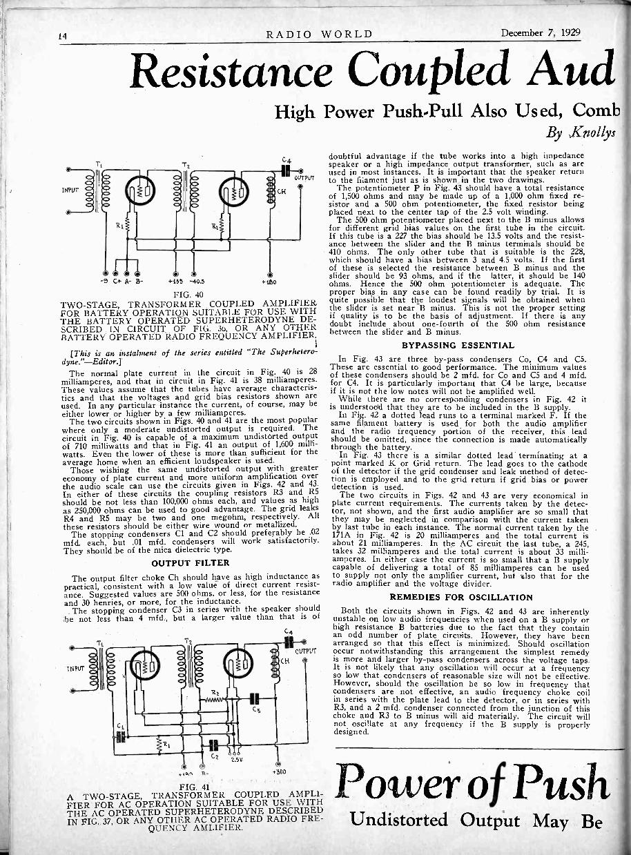
Resistance Coupled Aud
-s C+ A- B- 4-155 -40.5
High Power Push -Pull Also Used, CombBy Knollys
+ii5O
FIG. 40TWO -STAGE, TRANSFORMER COUPLED AMPLIFIERFOR BATTERY OPERATION SUITABLE FOR USE WITHTHE BATTERY OPERATED SUPERHETERODYNE DE-SCRIBED IN CIRCUIT, OF FIG. 36, OR ANY OTHERBATTERY OPERATED RADIO FREQUENCY AMPLIFIER.
[This is an instalment of the series entitled "The Superhetero-dyne."-Editorj
The normal plate current in the circuit in Fig. 40 is 28milliamperes, and that in circuit in Fig. 41 is 38 milliamperes.These values assume that the tubes have average characteris-tics and that the voltages and grid bias resistors shown areused. In any particular instance the current, of course, may beeither lower or higher by a few milliamperes.
The two circuits shown in Figs. 40 and 41 are the most popularwhere only a moderate undistorted output is required. Thecircuit in Fig. 40 is capable of a maximum undistorted outputof 710 milliwatts and that in Fig. 41 an output of 1,600 milli -watts. Even the lower of these is more than sufficient for theaverage home when an efficient loudspeaker is used.
Those wishing the same undistorted output with greatereconomy of plate current and more uniform amplification overthe audio scale can use the circuits given in Figs. 42 and 43.In either of these circuits the coupling resistors R3 and R5should be not less than 100,000 ohms each, and values as highas 250,000 ohms can be used to good advantage. The grid leaksR4 and R5 may be two and one megohm, respectively. Allthese resistors should be either wire wound or metallized.
The stopping condensers Cl and C2 should preferably be .02mfd. each, but .01 mfd. condensers will work satisfactorily.They should be of the mica dielectric type.
OUTPUT FILTERThe output filter choke Ch should have as high inductance as
practical, consistent with a low value of direct current resist-ance. Suggested values are 500 ohms, or less, for the resistanceand 30 henries, or more, for the inductance.,The stopping condenser C3 in series with the speaker should
;be not less than 4 mfd., but a larger value than that is ofC4
4.4C4IN+'500
FIG. 41A TWO -STAGE, TRANSFORMER COUPLED AMPLI-FIER FOR AC OPERATION SUITABLE FOR USE WITHTHE AC OPERATED SUPERHETERODYNE DESCRIBEDIN FIG. 37, OR ANY OTHER AC OPERATED RADIO FRE-
QUENCY AMLIFIER.
doubtful advantage if the tube works into a high impedancespeaker or a high impedance output transformer, such as areused in most instances. It is important that the speaker returnto the filament just as is shown in the two drawings.
The potentiometer P in Fig. 43 should have a total resistanceof 1,500 ohms and may be made up of a 1,000 ohm fixed re-sistor and a 500 ohm potentiometer, the fixed resistor beingplaced next to the center tap of the 2.5 volt winding.
The 500 ohm potentiometer placed next to the B minus allowsfor different grid bias values on the first tube in the circuit.If this tube is a 227 the bias should be 13.5 volts and the resist-ance between the slider and the B minus terminals should be410 ohms. The only other tube that is suitable is the 228,which should have a bias between 3 and 4.5 volts. If the firstof these is selected the resistance between B minus and theslider should be 93 ohms, and if the latter, it should be 140ohms. Hence the 500 ohm potentiometer is adequate. Theproper bias in any case can be found readily by trial. It isquite possible that the loudest signals will be obtained whenthe slider is set near B minus. This is not the proper settingif quality is to be the basis of adjustment. If there is anydoubt include about one-fourth of the 500 ohm resistancebetween the slider and B minus.
BYPASSING ESSENTIALIn Fig. 43 are three by-pass condensers Co, C4 and C5.
These are essential to good performance. The minimum valuesof these condensers should be 2 mfd. for Co and C5 and 4 mfd.for C4. It is particularly important that C4 be large, becauseif it is not the low notes will not be amplified well.
While there are no corresponding condensers in Fig. 42 itis understoo'd that they are to be included in the B supply.
In Fig. 42 a dotted lead runs to a terminal marked F. If thesame filament battery is used for both the audio amplifierand the radio frequency portion of the receiver, this leadshould be omitted, since the connection is made automaticallythrough the battery.
In Fig. 43 there is a similar dotted lead terminating at apoint marked K or Grid return. The lead goes to the cathodeof the detector if the grid condenser and leak method of detec-tion is employed and to the grid return if grid bias or powerdetection is used.
The two circuits in Figs. 42 and 43 are very economical inplate current requirements. The currents taken by the detec-tor, not shown, and the first audio amplifier are so small thatthey may be neglected in comparison with the current takenby last tube in each instance. The normal current taken by_ the171A in Fig. 42 is 20 milliamperes and the total current isabout 21 milliamperes. In the AC circuit the last tube, a 245,takes 32 milliamperes and the total current is about 33 milli-amperes. In either case the current is so small that a B supplycapable of delivering a total of 85 milliamperes can be usedto supply not only the amplifier current, but also that for theradio amplifier and the voltage divider.
REMEDIES FOR OSCILLATION
Both the circuits shown in Figs. 42 and 43 are inherentlyunstable on low audio frequencies when used on a B supply orhigh resistance B batteries due to the fact that they containan odd number of plate circuits. However, they have beenarranged so that this effect is minimized. Should oscillationoccur notwithstanding this arrangement the simplest remedyis more and larger by-pass condensers across the voltage taps.It is not likely that any oscillation will occur at a frequencyso low that condensers of reasonable size will not be effective.However, should the oscillation be so low in frequency thatcondensers are not effective, an audio frequency choke coilin series with the plate lead to the detector, or in series withR3, and a 2 mfd. condenser Connected from the junction of thischoke and R3 to B minus will aid materially. The circuit willnot oscillate at any frequency if the B supply is properlydesigned.
Power of PushUndistorted Output May Be

December 7, 1929 RADIO WORLD 15
to for Superheterodyneslining Resistance and Transformer UnitsSatterwhite
These two circuits are capable of the best quality of allpractical audio amplifiers. Moreover they are not only the mosteconomical in operation but also the least expensive to build.
In several popular commercial receivers the audio amplifierconsists of one stage of resistance coupling and one stage ofpush-pull. Such an amplifier is not only capable of fine tonequality, but also of a high undistorted output. Indeed, the out-put is nearly four times as high, for the same tubes and volt-ages, as that for the corresponding single tube output circuit, andthe quality depends on the grade of push-pull input and outputtransformers used.
Two such amplifiers are diagrammed in Figs. 44 and 45, thefirst for battery operation and the second for alternating cur-rent. The elements of these amplifiers have been discussedin the previous amplifiers and need not be discussed againexcept where differences occur.
SAME VALUES USEDThe coupling and grid leak resistors and the stopping con-denser capacity have the same value as the correspondingvalues of the resistance coupled circuits in Figs. 42 and 43.R1 in Fig. 44 is a 4 -ohm resistor and R2 a 2 -ohm resistor, the
first capable of carrying .25 ampere and the second .5 ampere.The grid bias resistor P in Fig. 45 should have a value justhalf as much as the corresponding resistor in Fig. 43. In thiscircuit only a 227 tube is suitable ahead of the push-pull stagebecause transformer coupling follows. Since the bias on thistube should be 13.5 volts, and further, since the total currentin the lower part of P is 70 milliamperes, the slider should beset at 193 ohms from B minus. Of the 70 milliamperes 6 arecontributed by the 227 and 64 by the two 245 tubes. Whitethe total value of P in this circuit should be 750 ohms it is allright to make it 800 ohms.It may be impractical in some instances to use fixed resistorsfor P, since the required value is not standard. There is acommercial resistor of 1,000 ohms capable of carrying thecurrent and having two sliders. One of these sliders can beused for adjusting the total resistance to the required valueand the other for locating the cathode return at the properplace to give a bias of 13.5 volts on the first tube.The current required by the circuit in Fig. 44 is about 47milliamperes and that required by the circuit in Fig. 45 is 70, as
was stated previously. This assumes that the first tube in Fig.44 is a 112A, which is recommended. The plate current ineither of these circuits is so high that a heavy duty B supplyis necessary if the same unit is to supply the radio frequencyportion. Of course it depends on how much current is takenby the radio frequency amplifier. But we have special refer-ence to the Superheterodyne circuit described. For the AC cir-cuit, particularly, it is recommended that two different B supplyunits be used, since this can usually be done more economicallythan using one which is substantial enough to handle the com-plete circuit adequately.
The tow side of the input in both of these amplifiers is treatedjust as it was in Figs. 43 and 44.
OUTPUT OF PUSH-PULL CIRCUITSThe maximum undistorted output of the circuit in Fig. 44 isabout 2.5 watts, a conservative value, while that in the circuitin Fig. 45 is around 6 watts. That is, the output of a push-pullcircuit may be as high as four times as great as that of asingle tube of the same kind and with the same voltages. Thisis not to be interpreted to mean that for the same input voltage
the output will be four times as great, but that the input canbe increased until the output is about four times before thetotal harmonic distortion will be the same percentage of thetotal input.If grid bias or power detection is used ahead of any oneof the circuits shown in Figs. 40 to 45, inclusive, the outputof the detector will be ample to load up the power stage to thehighest permissible limit. Of course the amplification in theradio and intermediate frequency amplifiers must be high
-Pull CircuitsFour Times Part of the Tube
F
B+ -4.5 AB- A+ -40.5c+
OUTPUT:
FIG. 42A TWO -STAGE, RESISTANCE COUPLED AMPLIFIERFOR BATTERY OPERATION SUITABLE FOR USE WITHANY RADIO FREQUENCY AMPLIFIER OPERATING ONDIRECT CURRENT. THIS AMPLIFIER IS CAPABLE OF
EXCEPTIONALLY FINE QUALITY.
enough to supply the required signal voltage on the grid ofthe detector.
It would be desirable to use a single audio amplifier tube ina receiver, because the fewer tubes used the better the chanceof retaining the quality of the output. The possibility of doingthis, however, is contingent on using a power detector which!is capable of delivering an undistorted signal large enough toload up the tube or tubes used as power amplifier. By using180 volts on the plate of the detector and 25 volts bias on thegrid it is possible by using a step-up transformer having aratio of about 4 -to -1 to get a signal of 38 volts on the poweramplifier. This is sufficient, or nearly so, to load up a singletube of the 171A type.
It would not be sufficient, however, to load up a 245 or eithertwo 171A or two 245 in push-pull. So when push-pull is used:or a single 245, it is desirable to use at least one intermediateaudio amplifier, and this might well be resistance coupled to thedetector. It is not recommended that the plate voltage on thedetector be increased much above 180 volts in order to get ahigher possible output, the only alternative for another stageof audio amplification.
RELATIVELY STABLEThe two amplifiers shown in Figs. 44 and 45 are relatively
stable because if the final stage is well balanced there is onlytwo plate circuits in which signal energy flows. However, ifthe power amplifier is unbalanced there may be considerablefeedback which may cause instability. It is not possible to tellwhether this feedback will result in a decrease in the amplifi-cation or in oscillation, because the action will depend on whichtube is the stronger. If the circuit oscillates with the powertubes in one way, they should be reversed, which should stopthe oscillation. Even if the circuit does not oscillate the tubesshould be reversed and that combination used which gives thebetter quality.
If the B supply leads and the grid voltage battery or bias.resistor are well by-passed, there should not be enough feed-back one way or the other to produce any noticeable effect.
C2 C5
z
KO---OA GRID
RETURN l2.511
AC+ 18000,155
+180
OUTPUT
FIG. 43THIS CIRCUIT IS ESSENTIALLY THE SAME AS THATIN FIG. 42 EXCEPT THAT IT IS DESIGNED FOR ACOPERATION. EITHER A 227 GENERAL PURPOSE TUBECAN BE USED IN THE FIRST STAGE, OR A 228 HIGH.MU HEATER TYPE TUBE.

16 RADIO WORLD December 7, 1929
(i) ANT.
171 A Push -Pull Output in Diamond
02
CAP222
8011411fiD0015d MCP
CT ,
0111 TGC3
IERI
NA 71I TS,.
.0440sIC4 24.0
2,TaRi
.00055MFR.
L4 ati
C5
111I2A
aArt
R
112
*SP
5P+
C
R5
PL
SW.
COW
THE CIRCUIT DIAGRAM OF THE BATTERY MODELPUSH-PULL, SCREEN GRID DIAMOND WHICH HASBEEN BUILT BY A LARGE NUMBER WHO ARE DE-LIGHTED AT ITS PERFORMANCE. IT IS SELECTIVE,SENSITIVE AND CAPABLE OF A HIGH UNDISTORTED
OUTPUT.
The audio amplifier of the battery model Push -Pull ScreenGrid Diamond three 112A tubes are used as diagrammed. Whilethis circuit is capable of sufficient undistorted output to satisfymost requirements in the home, some builders prefer to use171A tubes in the output stage to insure a still greater undis-torted output. When this change is made the tube ahead ofthe push-pull should be retained because its maximum undis-torted output working into a transformer is more than sufficientto deliver the necessary signal to a 171A push-pull stage to loadit up' to the limit.
The main changes required in the circuit pertain to the volt-ages applied on the push-pull tubes, as shown in the circuitbelow. In the original circuit the output is taken across thecenter -tapped choke coil L6, but in the circuit below an outputtransformer is used.
Since a voltage of 180 volts is used on the power stage in thesecond, circuit, this voltage is also used on the detector throughthe high resistance R3, which in the upper circuit is given as`.25 megohm. This is satisfactory in either case. It must berealized that when the amplifier given below is used in connec-tion ,with. the Diamond the B voltage supply must be of theheayy ,duty type since the push-pull tubes in the lower circuittake considerably more current.
The coupling resistor R3 was given above as 250,000 ohms,which is a suitable value when the detector precedes. The gridleak R4 may well be 2 megohms and the coupling condenser Cl,should be .02 mfd. Since the ballast iesistors R1 and R2 arenot represented directly in the complete circuit above, theyshould not be used when the amplifier is substituted in thereceiver.
A BATTERY OPERATED AMPLIFIER USING RESIST-ANCE AND PUSH-PULL COUPLING AND 171A OUTPUTTUBES WHICH CAN BE SUBSTITUTED IN THE DIA-MOND RECEIVER ABOVE WHEN GREATER OUTPUT IS
DESIRED.
8+135
5+221 To 45
C-714
Right a
(1)-Regeneration in a one tube set enhances both the seisitivity and the selectivity and the reason for this is that ttenergy fed back from the plate circuit to the grid circuit overcomes the radio frequency resistance in the circuit.
(2)-Neutralization in a radio frequency circuit is effected 1feeding back energy from the plate to the grid in such pha:and by such amount as to overcome the positive feedbacthrough the plate to grid capacity.
(3)-If neutralization, so called, is overdone the circuit bicomes insensitive.
(4)-There is no danger of oscillation in the intermedifrequency amplifier of a Superheterodyne because the fquency of operation is so low that the plate to grid capacis not large enough to cause sufficient feedback.
(5)-It is the oscillator in a Superheterodyne which detmines the selectivity of the receiver and this is readily provby observing the accuracy with which the oscillator condenmust be adjusted to get maximum volume.
(6)-If a receiver is built exactly in accordance withdirections of the designer of the circuit there is no danger tthat circuit will motorboat.
(7)-A receiver coupled with transformers throughout ismune from motorboating no matter what B supply is used,cause such a circuit cannot amplify the low frequencies suciently to sustain the oscillation.
(8)-The plate current in a receiving tube is oscillating ;is, it flows first in one direction and then in the other.
(9)-The plate voltage on a tube is only pulsating. It dnot oscillate.
(10)-Resistance coupled circuits are the most economicaloperate because the plate current in them is lower than tin any other type, and therefore both the amplifier and recti'tubes last longer.
Answers
(1)-Right. Both the sensitivity and the selectivity oreceiver depends on the amount of effective resistance intuned circuits, both being less the higher the resistance. Wthere is regeneration the energy loss in the resistance ofcircuit is supplied by the feedback and hence the effectresistance is reduced.
(2)-Right. Neutralization proper is a balancing arranment whereby a portion of the signal in the plate circuit is fl
back to the grid in opposition to that fed back through the tulcapacity. While there are many different variations of the mascheme they all work on essentially the same principle. TI
grid resistance method of so-called neutralization is notneutralizing method at all but only a losser.

December 7, 1929 RADIO WORLD 17
CIO.001 mfd
Thorough Filtering in B Supply
T1
T
6
O5 VOLTS2 AMR
280
C2
T2mfd.
C3 C4 C5
OM OM ....T2mfd 2 mfd ? Mfd
,C>V
C. 12 AMP
2 V
3 AMP
5W F 1AMP
II @ 110 VOLTSAC
ANT GNO.COMMON C- FOR 245
Wrong ?(3)-Right. This is correct not only for the different type
of true neutralizers but also for the losser method of stabilizingla circuit.
(4)-Wrong. The frequency cannot be too low, for evenin audio frequency amplifiers it is possible to induce oscillationin the same way. It is true, though, that the higher the fre-quency the more easily the circuit oscillates by virtue of thefeedback through the inter -electrode capacity.
11 (5)-Wrong. The oscillator has nothing to do with the selec-Itivity of the circuit, and all that the apparent sharpness of theoscillator shows is that the intermediate frequency filter isselective.
(6)-Wrong. This statement presumes that the descriptioniven by the designer covers all possible conditions of operation.bviously, no one can cover any subject so thoroughly, andarticularly not such a complex subject as motorboating.oreover, the term exactly is usually interpreted so loosely
hat any receiver whatsoever fits the case if the builder desires't to do so. Often an amateur builder will concoct his ownreceiver and call it by the same name given to a receiver bysome designer and then blame him if the set does not workatisfactorily.(7)-Wrong. There is no receiver which is immune from
notorboating, because the cause of this trouble is present in11 and the frequency of oscillation is not limited. Some of theest transformers now available are so efficient at low and sub -
audible frequencies that receivers coupled with them motorboateadily.
(8)-Wrong. It is pulsating and unidirectional. It can onlyow in one direction because the voltage source, battery or Battery eliminator, is always connected in the circuit in theme direction. It can drive current through the circuit in only
ne direction, but it can drive it through at different rates.oreover, the tube only admits current in one direction.(9)-Right. This was stated in the preceding answer. It
oes not oscillate, but pulsates. However, the variation in therrent behaves toward suitable coupling devices just as if itere oscillating.(10)-Right.' If a tube is powered so that it can deliver altage of about 100 volts to the succeeding tube in a trans-rmer coupled circuit, the plate current is about 10 milli-peres. If the tube is resistance coupled and powered so thatcan deliver the same voltage it can easily be adjusted soat the current is no more than one milliampere, or even one -nth milliampere. The less the current taken by the tube the
nger will the amplifier and rectifier tubes last, because thereonly a limited amount of life in any tube, and that life iseasured in ampere -hours.
-2 TV. -FOR 227, 224
TTTTEACH 8 mfd
0C+5 C+2 84-50 8+180 8+250FOR CATHODES FOR 245
DC VOLTAGES AS STATED --ARE AT 80 MILS MAX
THOSE WHO ARE LOOKING FOR A GOOD B SUPPLYUNIT AND FILAMENT TRANSFORMER CAPABLE OFPOWERING AN AC CIRCUIT OF FROM 'FIVE TO SEVENTUBES WILL FIND THIS SUITABLE. THE POLO B
BLOCK IS THE FOUNDATION.
One of the special features of the B supply unit depictedabove is the thorough filtering, that is, the use of many andlarge bypass condensers. This makes the circuit suitable foruse with high quality audio amplifiers in which there is dangerof motorboating when used with less thoroughly filtered B sup-ply.
It will be observed that the capacities across the lower sectionof the voltage divider in the B supply above are 8 microfarad.This means that they are electrolytic for condensers of suchlarge capacities cannot be obtained economically in any othertype. It would be desirable also to make the condensers C3, .C4 and C5 of this type for this would not only improve thefiltering but would make the B supply more efficient on a highquality amplifier. The total capacity of these condensers ifof the electrolytic type might well be 18 mfd.
It is especially suitable for a circuit in which the resistanceand push-pull coupled amplifier below is incorporated. The Bsupply not only furnishes the plate voltages for this circuit butalso the filament and heater current for the tubes. While thehighest voltage in the B supply circuit is given as 250 volts andthe highest called for in the amplifier below is 300 volts, thetwo really mean the same thing, for in either case the total DCvoltage is 300 volts. In the circuit above the 50 -volt bias requiredon the 245 tubes is not included in the computation while in thecircuit below it is. The actual voltages are the same, however.
R5
KO-- --OR GRIP1CrO RN
Rp
180 eit.155
Ti
6a
080 B -
T2
a-Ca0
+500
OUTPUT
THE CIRCUIT OF A SPLENDID RESISTANCE ANDPUSH-PULL COUPLED AC OPERATED AUDIO AMPLI-FIER WHICH IS CAPABLE OF ABOUT 5 WATTS OFUNDISTORTED OUTPUT. IT CAN BE USED WITH THE
B SUPPLY UNIT DEPICTED ABOVE.

16 RADIO WORLD December 7, 1929
® ANT.
171 A Push -Pull Output in Diamond
2CAP
222
SWAIM .010015C>
L3 c>C>
C>
L4
C4
2MEG II
.00035MFD.
Num
111C12
.000ts24-0
a
C5
R4
II2A 112A
*SP
*SP+
® 02 A
R51.34,
PL.C
SW. -..
* GNP.
THE CIRCUIT DIAGRAM OF THE BATTERY MODELPUSH-PULL, SCREEN GRID DIAMOND WHICH HASBEEN BUILT BY A LARGE NUMBER WHO ARE DE-LIGHTED AT ITS PERFORMANCE. IT IS SELECTIVE,SENSITIVE AND CAPABLE OF A HIGH UNDISTORTED
OUTPUT.
The audio amplifier of the battery model Push -Pull ScreenGrid Diamond three 112A tubes are used as diagrammed. Whilethis circuit is capable of sufficient undistorted output tomost requirements in the home, some builders prefer to use171A tubes in the output stage to insure a still greater undis-torted output. When this change is made the tube ahead ofthe push-pull should be retained because its maximum undis-torted output working into a transformer is more than sufficientto deliver the necessary signal to a 171A push-pull stage to loadit up to the limit.
The main changes required in the circuit pertain to the volt-ages applied on the push-pull tubes, as shown in the circuitbelow. In the original circuit the output is taken across thecenter -tapped choke coil L6, but in the circuit below an outputtransformer is used.
Since a voltage of 180 volts is used on the power stage in thesecond, circuit, this voltage is also used on the detector throughthe high resistance R3, which in the upper circuit is given as25 megohm. This is satisfactory in either case. It must berealized that when the amplifier given below is used in connec-tion ,witk the Diamond the B voltage supply must be of theheayy. duty type since the push-pull tubes in the lower circuittake cOnsiderably more current.
The coupling resistor R3 was given above as 250,000 ohms,which is a suitable value when the detector precedes. The gridleak R4 may well be 2 megohms and the coupling condenser Clshould be .02 mfd. Since the ballast 'resistors 121 and R2 arenot represented directly in the complete circuit above, theyshould not be used when the amplifier is substituted in thereceiver.
+MO -6 C* B- A+ +05 -40.5 4280
A BATTERY OPERATED AMPLIFIER USING RESIST-ANCE AND PUSH-PULL COUPLING AND 171A OUTPUTTUBES WHICH CAN BE SUBSTITUTED IN THE DIA-MOND RECEIVER ABOVE WHEN GREATER OUTPUT IS
DESIRED.
8+05
B+222 To 45
At
A- B -
C-710'4
Right (
(1)-Regeneration in a one tube set enhances both the sesitivity and the selectivity and the reason for this is that tlenergy fed back from the plate circuit to the grid circuit ovecomes the radio frequency resistance in the circuit.
(2)-Neutralization in a radio frequency circuit is effected 1feeding back energy from the plate to the grid in such phaand by such amount as to overcome the positive feedbagthrough the plate to grid capacity.
(3)-If neutralization, so called, is overdone the circuit bcomes insensitive.
(4)-There is no danger of oscillation in the intermediafrequency amplifier of a Superheterodyne because the frquency of operation is so low that the plate to grid capaciis not large enough to cause sufficient feedback.
(5)-It is the oscillator in a Superheterodyne which detemines the selectivity of the receiver and this is readily proveby observing the accuracy with which the oscillator condensmust be adjusted to get maximum volume.
(6)-If a receiver is built exactly in accordance with tldirections of the designer of the circuit there is no danger ththat circuit will motorboat.
(7)-A receiver coupled with transformers throughout is inmune from motorboating no matter what B supply is used, bcause such a circuit cannot amplify the low frequencies suflciently to sustain the oscillation.
(8)-The plate current in a receiving tube is oscillating; this, it flows first in one direction and then in the other.
(9)-The plate voltage on a tube is only pulsating. It dnot oscillate.
(10)-Resistance coupled circuits are the most economicaloperate because the plate current in them is lower than tin any other type, and therefore both the amplifier and rectifttubes last longer.
Answers
(1)-Right. Both the sensitivity and the selectivity ofreceiver depends on the amount of effective resistance in tltuned circuits, both being less the higher the resistance. Wh(there is regeneration the energy loss in the resistance of tlcircuit is supplied by the feedback and hence the effectiiresistance is reduced.
(2)-Right. Neutralization proper is a balancing arrangment whereby a portion of the signal in the plate circuit is f(back to the grid in opposition to that fed back through the tulcapacity. While there are many different variations of the mascheme they all work on essentially the same principle. TIgrid resistance method of so-called neutralization is notneutralizing method at all but only a losser.

December 7, 1929 RADIO WORLD 17
Clo.001 tni-cl
Thorough Filtering in B Supply
T5W F I Arm,'
110 Vot.r5AG
Ch1 Ch2
0 0 0ANT 4ND. C+.5 C+2 8+50 8+180 84-250
cominow C- FOR 245 FOR 227, 224 FOR CATHODES
Wrong ?
circuit.
(4)-Wrong. The frequency cannot be too low, for even
(3)-Right. This is correct not only for the different typef true neutralizers but also for the losser method of stabilizing
in audio frequency amplifiers it is possible to induce oscillationn the same way. It is true, though, that the higher the fre-uency the more easily the circuit oscillates by virtue of the
feedback throne' the inter -electrode capacity.(5)-Wrong. The oscillator has nothing to do with the selec-
ivity of the circuit, and all that the apparent sharpness of thescillator shows is that the intermediate frequency filter is
'selective.(6)-Wrong. This statement presumes that the description
given by the designer covers all possible conditions of operation.Obviously, no one can cover any subject so thoroughly, andparticularly not such a complex subject as motorboating.Moreover, the term exactly is usually interpreted so looselythat any receiver whatsoever fits the case if the builder desiresit to do so. Often an amateur builder will concoct his ownreceiver and call it by the same name given to a receiver bysome designer and then blame him if the set does not worksatisfactorily.
(7)-Wrong. There is no receiver which is immune frommotorboating, because the cause of this trouble is present inall and the frequency of oscillation is not limited. Some of thebest transformers now available are so efficient at low and sub -audible frequencies that receivers coupled with them motorboatreadily.
(8)-Wrong. It is pulsating and unidirectional. It can onlyow in one direction because the voltage source, battery or Battery eliminator, is always connected in the circuit in theame direction. It can drive current through the circuit in onlyne direction, but it can drive it through at different rates.oreover, the tube only admits current in one direction.(9)-Right. This was stated in the preceding answer. It
oes not oscillate, but pulsates. However, the variation in theurrent behaves toward suitable coupling devices just as if itere oscillating.(10)-Right.. If a tube is powered so that it can deliver a
oltage of about 100 volts to the succeeding tube in a trans-ormer coupled circuit, the plate current is about 10 milli-mperes. If the tube is resistance coupled and powered so thatt can deliver the same voltage it can easily be adjusted sothat the current is no more than one milliampere, or even one -tenth milliampere. The less the current taken by the tube the'longer will the amplifier and rectifier tubes last, because thereis only a limited amount of life in any tube, and that life is
easured in ampere -hours.
FOR 245
DC VOLTAGES AS STATED --ARE AT 80 MILS MAX
THOSE WHO ARE LOOKING FOR A GOOD B SUPPLYUNIT AND FILAMENT TRANSFORMER CAPABLE OFPOWERING AN AC CIRCUIT OF FROM FIVE TO SEVENTUBES WILL FIND THIS SUITABLE. THE POLO B
BLOCK IS THE FOUNDATION.
One of the special features of the B supply unit depictedabove is the thorough filtering, that is, the use of many andlarge bypass condensers. This makes the circuit suitable foruse with high quality audio amplifiers in which there is dangerof motorboating when used with less thoroughly filtered B sup-ply.
It will be observed that the capacities across the lower sectionof the voltage divider in the B supply above are 8 microfarad.This means that they are electrolytic for condensers of suchlarge capacities cannot be obtained economically in any othertype. It would be desirable also to make the condensers C3,C4 and C5 of this type for this would not only improve thefiltering but would make the B supply more efficient on a highquality amplifier. The total capacity of these condensers ifof the electrolytic type might well be 18 mfd.
It is especially suitable for a circuit in which the resistanceand push-pull coupled amplifier below is incorporated. The Bsupply not only furnishes the plate voltages for this circuit butalso the filament and heater current for the tubes. While thehighest voltage in the B supply circuit is given as 250 volts andthe highest called for in the amplifier below is 300 volts, thetwo really mean the same thing, for in either case the total DCvoltage is 300 volts. In the circuit above the 50 -volt bias requiredon the 245 tubes is not included in the computation while in thecircuit below it is. The actual voltages are the same, however.
DR GYMRETURN
IR3
LSO 0%135 4i80 B -
aaaaa
OUTPUT
THE CIRCUIT OF A SPLENDID RESISTANCE ANDPUSH-PULL COUPLED AC OPERATED AUDIO AMPLI-FIER WHICH IS CAPABLE OF ABOUT 5 WATTS OFUNDISTORTED OUTPUT. IT CAN BE USED WITH THE
B SUPPLY UNIT DEPICTED ABOVE.

18 RADIO WORLD December 7, 1929
A Question and AnswerDepartment conducted byRadio World's TechnicalStaff. Only Questionssent in by UniversityClub Members are ans-wered. Those not ans-wered in these columnsare answered by mail.
RADIO L NIVERSITY
Annual subscriptions areaccepted at $6 for 52numbers, with the privil-ege of obtaining answersto radio questions for theperiod of the subscrip-tion, but not if any otherpremium is obtained withthe subscription.
L- C4
FIG. 810THE THREE CONDENSERS IN THE TUNER OF THIS CIRCUIT CAN BE GANGED SINCE THE ROTORSARE ALL CONNECTED TO THE SAME POINT. THIS CIRCUIT IS CAPABLE OF HIGH SENSITIVITY AND
GREAT UNDISTORTED VOLUME.
A FADING PHENOMENONHERE is a nut for you to crack. And if you do it yon will
earn my everlasting gratitude. My audio amplifier con-tains one resistance coupler and one push-pull input
transformer. I also use a push-pull output transformer. Thereceiver is operated from a B battery eliminator. Here is thetrouble. The signals fade in and out in a quite regular manner.The trouble must be in the circuit because I have another setand that does not act that way. What might be the trouble?Suggest the cause and a remedy.-E. W. A.
Your receiver, in the first place, is very efficient on the lownotes and on frequencies below audibility. That is fortunate.Your B supply, in the second place, is not adequate for the job.That is not so good. It causes, in conjunction with your goodamplifier, an oscillation at a very slow frequency. The remedyfor this condition is not so simple as it would be if the oscilla-tion were at a higher frequency. More condensers across thevoltage taps in the eliminator are beneficial, and they will curethe trouble if they are large enough. Having used up all thecondensers you have, or all that you can buy, the next thing isto reduce the value of the grid leak until the oscillation stops.If the resistance has to be reduced so much that the signalsalso are greatly reduced, change the stopping condenser in theresistance coupler for one of lower value.
* * *
ESTIMATING PLATE CURRENTCAN YOU suggest a good method for estimating the total
current that a radio receiver will take when the plate andgrid voltages and the number and type of tubes are given?
I realize that if the current in any one tube is known under thespecified conditions all the current can be obtained by addition.Hence give thq method for obtaining the current in any tube.-E. A. Z.
There are tables and curves available for all the tubes incommon use, and these should be consulted. There is no otherway. Either take the values of current obtained by others ormeasure the current yourself. The most useful tables or curvesare those which give the relationship between the plate voltageand the plate current for different values of grid bias. Suchcurves were given in several issues of RADIO WORLD lastFall and they are also given in Audio Power Amplifiers, by J.E. Anderson and Herman Bernard. In using curves select thebias desired and follow the line until the applied plate voltageline is reached, and read the corresponding current. Do thesame for all the tubes in the set. If there are more than onetube of the same kind and operating under the same conditionssimply mulitply the current for one tube by the number ofsimilar tubes.
* * *
CALCULATING POWER REQUIREDHOW can I determine the total power taken by an AC re-
ceiver without measuring the input to the transformer ortransformers connected to the lighting circuit? Is there
any way, without using meters?-H. A. F.Some meters must be used to get a close estimation of the
power required, but the measurement can be done with those
meters available to most set owners, that is, voltmeters and mil-liarinneters. Many set owners now have circuit and tube testerswhich contain all the meters necessary. First figure out thepower required by the filaments of all the tubes in the set, in-cluding the rectifier. This power can be estimated quite closelyby taking the rated filament currents and the rated filament volt-ages. The power expended in any filament, or heater, is theproduct of the current and the terminal voltage. For example,if the rated filament voltage and current of a 250 are 7.5 voltsand 1.25 amperes, the power required is 9.375 watts. The powerfor the others is obtained in the same way.
After the filament power has been obtained the plate powershould be computed from the highest DC voltage in circuit andthe total plate and bleeder currents. The product of the highestvoltage and the total current is the plate power required. Add thisto the filament power and increase the sum by about 20 per centto allow for losses in the transformers. The results are close tothe power taken from the AC line. If you have an AC ammeter,connect it in series with the primary of the power transformerto get the total AC current. Multiply this with the normal volt-age of the line, say 110 or 115 volts, and the results is approxi-mately equal to the power taken by the receiver. This valuemay be a few per cent high.
If you want to get the cost of the power it takes to operatethe set, multiply the power by the cost per kilowatt hours andyou get the cost per hour. For example, suppose that the com-puted or measured value of the power required is 60 watts andthe price of electric energy is 7.5 cents, the cost per hour ofoperating the set is 7.5 x .06 cents. That is, .45 cents per hour.Of course, this is a small part of the total cost of operation ifthe depreciation of the tubes and the receiver is taken intoaccount, but even if this is counted in the cost will not be morethan a few cents per hour.
* * *
HE WANTS A COMPLEX CIRCUITWILL YOU kindly publish a circuit diagram of an AC
receiver containing three screen grid tubes, includingthe detector, one 227 audio amplifier and two 245 tubes
in push-pull? I would prefer one in which the tuners areshielded and in which the condensers can be ganged. I havefollowed very carefully your discussions on power amplifiersand I believe that I can fill in all the different values myself.At any rate I want to try my knowledge on the circuit and ifI get stuck I'll impose on your good nature once more.-W. A. S.
Fig. 810 contains a circuit which seems to fill all the require-ments. It is a straightforward circuit in every respect and com-plete with the exception of the B supply. Two features mayneed special attention, although you may have studied themin the series on power amplifiers. We refer to the method ofgetting proper bias voltages on the detector and the first audioamplifier. As a suggestion, R2 and R3 should have a totalresistance value of 25,000 ohms and the sum of R4 and R5 mayhave the same value. However, there is no great need of usingR5, since the plate current in this stage is considerable. If R5is not used R4 should be determined on the basis that the platecurrent alone flows through R4.

December 7, 1929 RADIO WORLD 19
INTERESTED IN CRYSTALSIHAVE ALWAYS been partial to crystal rectifiers because
of the excellent quality which can be obtained with them,and I should like to know on what principle they operate ;
that is, what makes them rectify. I would appreciate a full dis-cussion of it.-M. 0. G.
The ,superiority of crystal detection in respect to quality overtube rectifiers is a fiction pure and simple. It arose from thefact that at the beginning tube detectors were used in conjunc-tion with very bad amplifiers and still worse loudspeakers,whereas crystal rectifiers were used directly on head sets. Ityou hook up the same amplifier to a crystal set and a tube de-tector you will get practically the same quality, but the crystalset will be much less selective. The difference in selectivity,however, is not so great as to account for any difference in thequality that may be thought to exist. Respecting the principleon which a crystal works, there is no agreement among thosewho have studied the crystal enough to have any opinion worthattention. Some say that the rectification occurs in the body ofthe crystal, others say that it takes place at the surface. In thisrespect probably both are right, for there are many differentcrystals. Some authorities think that the effect is thermal andothers believe it is chemical. The chemical idea seems to havethe upper hand, because the rectification seems to be similar tothe rectification of dissimilar metals now used considerably inpower supply devices. But the question is still open.
* * *
MODULATION CAPABILITYRECENTLY I have seen the term "modulation capability."
Is that an equivalent statement to per cent. modulation?There are now supposed to be stations the waves of
which are modulated 100 per cent. Is such high modulationreally possible?-D. J. W.
A transmitter radio frequency current is not modulated atthe same percentage all the time, but depends on the intensityof the sound that is being transmitted. A very weak sound maynot modulate the wave by more than one per cent. and a strongsound may modulate it 100 per cent., or it may even overmodu-late it. The modulation capability is the highest percentagemodulation of which the transmitter is capable without produc-ing distortion. In modern transmitters the highest percentageis 100 per cent., or complete modulation. This does not meanthat the wave is ever modulated to this extent, but that itmay be during occasional bursts of sound. Such high degreeof modulation is not desirable unless straight line rectificationis used in the receiver. Since high degrees of modulation aredesirable from the point of view of channel and power economy,there is no doubt that in the future all broadcast stations willhave a 100 per cent. modulation capability and all receiverswill have straight line detection. We are rapidly approachingthat state of development.
* * *
EMISSION TEST ON 112A TUBEKINDLY SUGGEST a metho'd of making emission tests
on the 112A tube, and give the current that can be ex-pected. I have the information necessary for making such
tests for all the other standard tubes but have not been ableto find any directions for this tube.-J. C. D.
Emission tests should not be taken on this tube. Test it asan amplifier. What does an emission test indicate anyway?There are cases when emission tests will indicate the true con-dition of a tube, for example, if the plate current is very highand the tube still refuses to work, the tube is gassy and theemission will apparently be very large. The 112A tube willshow a blue glow when it is gassy.
* * *
PROPER CONNECTIONS OF RF COILSWHAT ARE the proper connections of a radio frequency
transformer in which the primary and the secondary arewound on the same form ? Does it really make much
difference just so the primary is in the plate circuit and thesecondary in the grid circuit?-D. A. M.
Assuming that the two windings are in the same direction,that is, such as would be the case if a single winding were cutat a suitable point to produce on terminal for the secondaryand one for the primary, these two terminals should go to Fminus and B plus, respectively. The outside terminal of thesecondary should go to the grid and the outside terminal of theprimary should go to the plate. This is the preferred Way, butit really does not make much difference which way the terminalsare connected, subject to your own proviso. However, if oneparticular method is selected for one transformer in a circuit,the same should be used for all. If the coil is to be used as anoscillator and both the extreme terminals are connected to thesame tube, oscillations will not occur unless the above connec-tion is used. There is one alternative connection for an oscilla-tor, and that is to connect the inner terminals to the grid andplate and the outer terminals to F and B. But electrically this
) connection is essentially the same as the first.* * *
SUGGESTED EQUALIZATIONUNDERSTAND that the amplification in resistance coupledcircuits is low on high frequencies due to inter -electrodecapacities, and also if the load on the tube is inductive the
amplification is high for the same reason. If that is so, would
SECONDARY OFqF TR ANSFORME R
6r
FIG. 811A SIMPLE RECTIFIER CAN BE CONSTRUCTED WITH
A RECEIVING TUBE AS RECTIFIER BUT IN MOSTINSTANCES IT IS NECESSARY TO USE A TRANS-FORMER BETWEEN THE LINE AND THE RECTIFIER
EVEN WHEN A LOW VOLTAGE IS WANTED.
it not be possible to equalize the amplification by connectinga small inductance in series with the coupling resistor.-E. H. H.
It is so all right, for one of the defects Of resistance couplingis that the amplification is low on the highest audio frequencies.It is also true that circuits having inductive loads oscillateat high frequencies, or at least amplify more than at low. Itdoes seem possible to equalize the amplification just as yousuggest. We cannot recall a circuit, however, in which it hasbeen done, nor do we recall any experimental work on it.But the scheme is not worth while in an amplifier designedfor broadcast reception or for use with any audio circuit,because the reduction in the amplification is not appreciableinside essential audio frequency band. For special circuits, suchas television and picture receivers it might be worth while.There are other ways of getting full amplification up to ashigh as 30,000 cycles per second.
* * *
A SIMPLE RECTIFIERIS IT POSSIBLE to use a small receiving tube heated with
direct current as a rectifier in a low power Z supply unitwithout using any input transformer I can see no reason
why this arrangement should not work. If there is any pleasepoint them out. A circuit diagram would be appreciated.-B. D.
Under certain conditions this is possible, but the tube usedmust be large enough to supply all the current that is required.The arrangement does not always work for ground on the lineand the ground on the set may cause a partial or total short-circuit. If, however, an input transformer is used it works everytime. Fig. 811 shows a circuit containing a six -volt tube asrectifier. The input plug should go to the secondary of a trans-former the primary of which is in the line. Unless only a fewmilliamperes are wanted it is best to use a regular rectifiertube.
1.
Join
Radio World's
NIVERSITY CLUBAnd Get Free Question and Answer Service for the Coming
52 Weeks. This Service for University Subscribers OnlySubscribe for RADIO WORLD for one year (52 numbers)Use the coupon below. Your name will be entered on our sub-scription and University Club lists by special number. Whensending questions, put this number on the outside of the for-warding envelope (not the enclosed return envelope) and alsoput it at the head of your queries. If already a subscriber,send $6 for renewal from close of present subscription andyour name will be entered in Radio University.
NO OTHER PREMIUM GIVEN WITH THIS OFFER[In sending in your queries to the University Department picas.
paragraph and number them. Write on one side of sheet only41ways give your University Club Number.]
RADIO WORLD, 145 West 45th Street, New York City.Enclosed find $6.00 for RADIO WORLD for one year (52 nos.)and also enter my name on the list of members of RADIOWORLD'S UNIVERSITY CLUB, which gives me free answersto radio queries for 52 ensuing weeks, and send me my numberindicating membership.
Name
Street
City and StateIf renewing subscription, put cross here. 0

20 RADIO WORLD December 7, 1929
JERSEY FIGHTS
NEW WABC SITE
AS BLANKETINGWashington
The State of New Jersey is making adetermined fight to prevent the incursion ofthe Columbia Broadcasting Company intoits territory. The System recently wasgranted a license by the Federal Radio Com-mision to build a 50,000 watt transmitter forits key station, WABC, at Columbia Bridge,near. Morristown, N. J. The present trans-mitter, is on the outskirts of New York City.The New Jersey Radio Commission wasgranted a hearing before the Commission atwhich every effort was made to have thepermit rescinded.
The New Jersey Radio Commission issueda statement in which it is said that the newWABC high -power transmitter, if placednear Morristown, will effectively "blanketthat city, together with Montclair, theOranges and Newark." Engineers of theWestern Electric Company, designers andbuilders of the transmitter, say, however,that little fear need be felt on this score,tests having shown that interference of the"blanketing kind" is normally not foundmore than a mile from the transmitting an-tenna when modern receivers are used.
"This attitude on the part of the NewJersey Radio Commission does not reflect inany way on WABC or any other station,"the radio board representative explained,nor on the quality of the programs broad-cast by out -of -the -State radio facilities. Itis merely that New Jersey thinks it shouldhave a say in the question of whether anysuch broadcaster may set up a station onState soil without the people having a voicein the matter. It is understood that suchtransmitters ruin reception for listeners whoreside nearby.
Good News forRadio Dealers
Have you heard about it? Did youread the New York Times a few daysago to the effect that, notwithstandingthe recent stock slump, R. H. Macy, B.Altman & Co., Arnold Constable & Co.,John Wanamaker, Bloomingdale's andGimbel's, the biggest department storesin New York-and maybe that means theworld-announced that the recent jolt inthe stock market had not affected theirsales? As a matter of fact Macy saidthat the November sales of store wasthe biggest in the history of the firm.Every one of the stores has shown anincrease in sales over last year.
Radio dealers, why not you?
Silver Back on JobAfter Auto Accident
ChicagoMcMurdo Silver, president of Silver -
Marshall, Inc., was back at his desk aftera month's absence due to injuries incurred inan automobile accident.
His health is completely recovered, andhe has assumed all his former duties whichwere handled during his absence by a com-mittee of three.
Literature WantedTHE names and addresses of readers of
RADIO WORLD who desire literatureon parts and sets from radio manufac-
turers, jobbers, dealers and mail orderhouses are published in RADIO WORLDon request of the reader. The blank atbottom may be need, or a poet eard or let-ter will do instead.
RADIO WORLD,145 West 45th St., N. Y. ( Ity.
I desire to receive radio literature.
Name
Address
City or town
State
R. J. McCutcheon, c.o. Colorado Fuel & IronCo., Pueblo, Colo.
W. B. Bartholomew, Cleveland Ave., OBS. Sta..Pittsburgh, Pa.
Harold L. Casto, 229 Chester Ave., N. S., Pitts-burgh, Pa.
W. W. Kroeger, Box 18. Sidney, Neb.Edward Taylor, 1394 E. Hewson St., Phila.. Pa.A. Freedman, 1781 77th St., Brooklyn, N. Y.L. A. Weiss, R. F. D. 8, Parkview Ave., Kala-
mazoo, Mich.L. E. Dunston, Box 143, Athens, Ga.Don Drenner, 221 E. "D" St., Oklahoma City,
Okla.Caswell Radio Repair Service, R. R. No. 1,
Dayton, Ohio.0. L. Billingsley, P. 0. Box 22, Brownwood,
Texas.Earle W. Stahl, 499 Madison St.. Milwaukee,
Wis.M. C. Miller, Box 117, Centerville, Crawford
Co., Pa.John A. Coy, 224 East Court St., Apt. 208, Flint,
Mich.H. G. Knab, 238 13th St., Brooklyn, N. Y.Kneiling's Radio Shop, 812 No. State St., Tacoma,
Wash.Ed. Roberts. Fen'l. Del'y., Lubbock, Texas.Ray E. Krout, 1218 Topping, Kansas City, Mo.W. B. Lucas, R. F. D. No. 1, Pasco, Wash.Peter J. McEntee, 1210 Woodycrest Ave., New
York City.Peter Bella, 218 Nimrod St., Brooklyn, N. Y.Ralph Quarles, 324 W. 53rd St., New York City.C. H. DeLander, 1839 N. Bryant, Minneapolis,
Minn.J. W. Squires, co. Taft School, Watertown.
Conn.
ForumWE WON'T
ICAN NOT refrain from offering a wordof congratulation on your excellentmagazine. While others seem to be
finding it difficult to maintain fan interestyou show a constantly improving facilityin that direction and RADIO WORLD hascome with us here to be a sort of con-temporaneous and up-to-the-minute textbook. We wish you continued success,and don't let anybody tell you there oughtto be more general news and fewer tech-nical articles.
E. W. MATTHEWS,Augusta, Ga.
* * *
SHOUTS FOR BIGGER SETSIAM INTERESTED in the MB -29 be-
cause it is not the same old infernalfour tuber. I know nothing of the coils
or how to make them. This simply meansthat I have .0005 Hammarlund condensersand drum dials on hand and would notdiscard them. They are good. I alsohave sockets and condensers by thebunch. Now can a man be expected tobuy a whole new outfit every time a newset comes out? That is why I am shout-ing for a six or seven tube set as a fea-ture article in RADIO WORLD with full de-tails. You can do it if you want to.Have some variety, please. I was listen-ing to N. Y. at 3 P. M. this afternoon ona factory set. Will any of yours do that?
W. A. WEST,Halifax, N. S.
DATE SLIP-UP
BARS STATIONS
ON RENEWALSWashington
Two cases were dismissed by the Courtof Appeals of the District of Columbiaon like issues like those on appeal fromdecisions of the Federal Radio Commis-sion. The By -Products Coal Company,of Bypro, Ky., and the J. P. Burton CoalCompany, of Cleveland, Ohio, which hadpreviously maintained between the twolocations a limited point-to-point radio-telegraph service, lost their plea for re-newal because they had not filed theirappeal within the twenty -day periodspecified b law.
"The action of the court," the generalcounsel of the Commission, B. M. Web-ster Jr., said, "is significant in that thecourts' action upholds a rule of the Com-mission that the date of the Commis-sion's decision in a given case, unlessotherwise specified by the Commission,is the effective date of that decision.
"The same issue arose in the case ofthe General Electric Company v. theFederal Radio Commission," Mr. Web-ster said, "the first case taken to theCourt of Appeals under the radio act of1927. The motions in that case were notpassed upon by the court, although byproceeding to render a decision on themerits of the case, the court, in effect,denied the motions."
RADIO WORLDAS A CHRISTMAS GIFT
Many persons have found that theirfriends appreciate subscription for RADIOWORLD as Christmas gifts. Why not sendthat friend of yours-especially theschoolboy who finds so much of realvalue in our columns-RADIO WORLD as a52 -weeks' gift? Send us $6 with thename and the address of the person towhom you want the copies to go, andwe shall see that your friend is advisedto whom he is indebted for the yearlysubscription.
Send now and the subscription will besure to start during the holiday season.RADIO WORLD, 145 W. 45th St., N. Y. City.
Board is Hard UpFor Payroll Funds
WashingtonThe Federal Radio Commission had less
than $300 on hand to meet a $15,000 pay-roll. A proposed transfer of $25,000 fromthe Department of Commerce appropria-tion to the Federal Radio Commissionhas been disapproved by the ComptrollerGeneral of the United States, J. R. Mc -Carl.
The appropriation of the Commissionfor the fiscal year was $164,440 and therestill remains of this fund $45,000 for op-erating expenses, but under law this maynot be used for pay -roll purposes.
A THOUGHT FOR THE WEEKrmore radio stores would stress servicea little more and "unheard of prices" alittle less, that ill-favored, interjectional
appellation, "Gyp!" would be heard lessfrequently throughout the land.

December 7, 1929 RADIO WOR 1,1) 21
CRYSTAL TRUE
TO 5 PARTS IN
EVERY MILLIONWashington.
Great contributions to the advancement ofradio as a science and as an art and toaviation have been made by the Bureau ofStandards, as evidenced by the annual reportof the Director, Dr. George K. Burgess.
Extracts from the department's summaryof the report as appertaining to radio, fol-lows:
"Among important developments listed inthe report are the new type visual airplaneradio beacon, improved methods of protect-ing electrical airplane equipment from radiointerference, and better quartz oscillatorsfor use in radio transmission.
Accurate Quartz Oscillators"A new type of visual airplane -radio bea-
con sending out ariy number of courses up to12 was developed.
"Methods of shielding the electrical equip-ment of airplane engines have been devisedto eliminate radio interference, and confer-ences have been held with manufacturersof engines and ignition systems.
"The type -testing of commercial engineshas grown into one of the most importantlines of test work at the Bureau and is adirect safeguard for every passenger on acommercial plane. As a result of experi-ments made in the Bureau the noise in anairplane cabin will be greatly reduced.
"The radio section has succeeded in im-proving the quartz oscillators used as funda-mental standards of frequency, so that theerror in constancy of these instruments doesnot exceed five parts per million.
Sun Spot Theory Proved"The precision of the methods used in test-
ing oscillators for broadcasting stations hasbeen increased tenfold. The study of thefundamentals of radio transmission has con-tinued, and it has been found that daylightradio signal intensity varies directly anddaylight static inversely as solar activity.
"In other words, the relationship betweenradio signal transmission and the sun -spotcycle seems established beyond doubt."
Number of StationsDrops to Below 600
WashingtonThe Federal Radio Commission recently
announced that for the first time since thatbody assumed control of the radio situation,more than three years ago, the number ofbroadcasting stations operating in the UnitedStates has dropped below 600.
When the Commission took over control,February 23rd, 1927, records show, therewere 733 broadcasting stations on the airholding licenses from the Department ofCommerce, the Commission's predecessor.
Radio Signal ServicePerfected for Planes
A new use for radio is a signal servicefor air lanes to cover every square mile ofAmerican territory where planes fly. Thiswill be developed and put in use by theAeronautics Bureau of the Department ofCommerce, which is completing the greatestand most widespread weather informationset-up ever _established in any country.
Twenty-four stations located in variousstrategic parts of the country are alreadyhooked -up for this service.
Baird TelevisionReady for Proof
The Baird system of television, devel-oped by John L. Baird, Scottish inventor,soon will be demonstrated in the heartof New York City, according to a state-ment issued by Captain 0. G. Hutchin-son, general manager of the Bairdinterests.. The system is said to requireonly the width of wavelength used byAmerican broadcasting stations.
"We are here to prove that televisionis an established fact. It can be madeimmediately acceptable in the home asan educational and entertainment featurethrough present radio broadcasting fa-cilities," said Captain Hutchinson. "Itis now possible, using the ordinary wavebands allotted for speech and musicbroadcasting, to transmit images andvoices on the program wave lengths.Such broadcasting is being done throughLondon, Berlin and many other stations,using the Baird system. British radio setowners are receiving television from 2L0daily and the German radio public fromthe station at Witzlieben."
CATHODE RAY
REPLACES DISKA new system of television in which the
cathode ray tube is utilized in place of theformer method of scanning the image bymeans of the conventional disk was dem-onstrated befote the Institute of Radio En-gineers Convention in Rochester, N. Y.
Dr. Vladimir Zworykin, research engineerof the Westinghouse Electric and Manufac-turing Company, demonstrated the apparatusand pointed out that its use will make pos-sible the transmission of motion picture andsynchronized action without pre-emptingnumerous valuable wave channels nowrequisite for television purposes.
The cathode ray television receiver has nomechanical moving parts. It is quiet in op-eration and produces a picture with lessflicker than systems using scanning disks.
The picture now possible with apparatusalready developed is approximately four byfive inches in size, but the inventor pointedout that additional experiments will un-doubtedly lead to tubes which will producelarger pictures.
Chain Stores ProtestKWKH Talk as Slur
Statements alleged to be made over theair derogatory to chain stores, through themedium of KWKH, at Shreveport, La., byits owner, W. K. Henderson, have 'resultedin complaints to the Federal Radio Commis-sion from trade associations and chain storesthroughout the South.
Approximately forty telegrams, it wasstated, were received on one day from chainstores within service range of the Shreve-port station asking the Commission to takeaction. It is said that R. W. Lyons, of NewYork, executive secretary of the NationalChain Stores Association, including in itsmembership such organizations as Sears -Roebuck and Montgomery -Ward and Com-pany and other National chains, also wroteletters of protest to the Commission.
Next Week-Christmas Numberof Radio World!
BILL CONTINUES
BOARD A YEAR
AS EXECUTIVESWashington
At the regular session of Congress, a jointresolution to be introduced by Senator Dill(Dem.), of Washington, and RepresentativeWhite (Rep.) of Lewiston, Me., will pro-pose indefinite continuation of the executivelife of the Federal Radio Commission.These legislators have been co-authors fromtime to time of resolutions extending thelife of the Cott mission and amending theradio law otherwise.
"We want the Radio Commission to liveuntil a communications commission is cre-ated," said Mr. Dill, who is a member of theInterstate Commerce Committee, beforewhich is now pending the bill (S. 6) of thechairman, Senator Couzens (Rep.), ofMichigan, to create a commission on com-munications and power.
Controversial Subjects Out
Regarding the resolution which will bedrawn, Senator Dill said, "it will not con-tain any controversial amendments to thepresent law. It was at first planned to in-clude an amendment to the act, repealing theDavis equalization amendment, and makingsome changes in procedure on appeals.
Senator Dill added, "that the resolutionto continue the Commission might not hepassed before the Christmas holidays, butthat the regulating authority of the Commis-sion would simply revert back to the Secre-tary of Commerce on the first of the yearand continue under his authority."
Must Continue, Says Davis
Representative Davis (Dem.), of Tulla-homa, Tenn., in giving his views on the pro-posed resolution, said he favored not onlyinclusion of sufficient funds in a deficiencybill to meet the Radio Commission's pay rolldiscrepancy but also extension of the life ofthe Commission.
"I was the first in either House of Con-gress publicly to advocate a Federal commis-sion on communications," he said. "I stillbelieve in it and I believe it will ultimatelybe brought about. Meantime, everybodymust realize that there is no alternative butto continue the Federal Radio Commissionuntil such time as other Federal machineryfor the purpose can be set up."
Anti -Noise Body
Gets Speaker ComplaintsIn New York City by the movement to
abate unnecessary noises has caused someremarks about radio as a source of com-plaint. In response to questionnaires sentout by the Noise Abatement Commission,1,500 answers list as noises most offensiveand nerve-racking, shrill and far-reachingradio loudspeakers and amplifiers, rum-bling trucks and screeching auto horns.
Many also complained against over-loaded demonstration amplifiers used bydealers in front of their places of busi-ness.
RADIO WORLD'S BOOK SERVICEhas been found of great value not onlyby radio fans, constructors, etc., but alsoby radio and other technical schoolsthroughout the country. See the radiobooks advertisements in this issue.

77 RADIO \V O R L D December 7, 1929
TERRELL LAUDS Crystal Standard
17,000 "HAMS" Invitations to a conference to be held
Sought by NavyWashington.
by the Bureau of Engineering, Depart -
ASKS SUPPORTtent of the Navy, have been issued tothe Radio Corporation of America, Gen-eral Electric Co., Westinghouse Electric& Manufacturing Company, GeneralRadio Company and the American Op-
The difficult task of "policing the tical Company, among others. Theether," performed by the radio division object is unoformity of production ofof the Department of Commerce, will be quartz crystal controls employed inmade easier when new equipment now maintaining radio transmitters on specificon order is placed in service, according frequencies, in the interest of reducingto the report of W. D. Terrell, chief of interference.the division. Notable among the ap- The crystal controls now made com-paratus, said Mr. Terrell, will he the mercially are not uniform, it was stated,constant -frequency monitoring station, or with the result that the product of one"master radio traffic cop," now being in- laboratory may not be interchangedstalled in the geographical center of the with that of another, even if both arecountry-at Grand Island, Nebr. This prescribed for the same frequency. Suchstation, situated on a 50 -acre tract, will conditions can be corrected if specifica-cover the entire range of the spectrum, tions are agreed upon. All departmentsand from it transmitters the world over of the Government interested in radiomay be checked as to their frequency. have also been invited to participate inThe very latest in radio -checking ap- the conference.paratus is being installed, he said. Thestation will be complete within itself,generating its own energy and a 24 -hour -a -day service will be insuredthroughout the year.
A fine tribute to the American ama-teurs, totaling approximately 17,000, waspaid by Mr. Terrell, who said that whileother countries are worrying over theproblem of controlling, taxing and dis-couraging the few surviving amateursthey have, he said, "this country is con-stantly endeavoring to keep this largegroup of experimenters engaged in usefuland interesting work."
1661. 6.6616 C661.1 36i
6 6616 Tos6 W. Nome, SA
6106 N6616,1664 %.
6 t656 It,.,. 601 661II6,6.1110ertialt5ie$1.111./
6.46.65, IV a C Cerist
Fourteen CircuitsEach Shown in Colored Picture Diagram,Colored Schematic Diagram and Front
Panel LayoutGet This FREE Book!
Complete AC electeio receivers, with B eliminatorsincluded, also AC receivers without B eliminators, alsobattery operated models, all easy -to -build circuits, usingyour own parts.=I INIM I = IBMS 11 /ISRADIO WORLD, 143 W. 45th St.. N. Y. City.(Just East of Broadway)
Get a real kick out of listening to foreign stationsGentlemen: Enclosed pleas. find $1.00 for which pleasesand me Radio World each week for eight weeks (regular on a real short-wave circuit, the National ThrillPrice, $1.90) and besides send me a FREE copy of the Box. Uses one 222 screen grid RF amplifier, one1929 edition of The Radio Blueprint Library of AC andBattery Hookups. 200A detector, one 240 first audio and one 171A
or 112A output. Single control. Buy the partsName and build the circuit in two hours. Data sheetAddress shows dial settings where foreign stations come in.
Cat. SW4EF, all parts, including decorative brownCity State steel cabinet, all six plug-in coils, list price $51.90
Note: Present mail subscribers may take advantage of (less tubes). Your price $31.00.this offer by putting a cross in this square. 0 Your sub-scription will be extended eight weeks.
[Canadian remittance must be by postal or express Guaranty Radio Goods Co.money order, due to high discount rate on cashingCanadian chocks in New York.] 143 West 45th Street New York City
INCOME TAX IS
LICENSE PLANA schedule of fees to be imposed on
all radio broadcasting stations will beproposed in radio legislation to be spon-sored soon by Senator C. C. Dill of theState of Washington. A fee of 20 centsper watt for broadcasting companies anda flat license charge for communicationcompanies, together with a pro rata taxon net incomes has been suggested bymembers of the Commission in confer-ence with the Washington Senator.
Ira E. Robinson, chairman of theCommission, in testimony before theSenate Interstate Commerce Commission,expressed himself as favoring suchlicense fees.
Short Wave Circuit
Naleueing I nrau isoa, 4 -tubs short wave circuit, 15 to 595-"eters, battery -operation of filaments; B supply, either
batteries or eliminator.
BOARD FIGHTS
KWY ATTEMPT
TO CLINCH WAVEWashington.
The suit brought by KYW, KFKXand KYWA, Westinghouse stations inthe Chicago area, to compel the FederalRadio Commission to issue unrestrictedlicenses for operation on 1,020 kilocycles,is being fought by the Commission onthe ground the renewal licenses werejust like the former ones in effect. Alsothe board asks dismissal of the appealon the ground the stations were late infiling it, and besides there is no pro-vision of law under which the appeal canbe taken.
The appeals claimed that the Commis-sion had not renewed the licenses of thestations in exact accordance with the ap-plications, but had inserted in the licensea clause to the effect that the 1,020 -kilo-cycle channel properly belongs to theSecond or East-Central Zone under thereallocation order of the Commission andthat it merely was loaned to the Fourthor Middlewestern Zones, in which KYWand KYWA are located.
The clause was inserted in the renewalsfor the 90 -day period which began No-vember 1st.
It was pointed out that KYW uses10,000 watts power, 5,000 of which isissued experimentally, and that KYWAis used as a "booster" station, being auto-matically synchronized by wire with themain station.
The language inserted in the licensesfor the current licensing period, specify-ing that the 1,020 -kilocycle channel be-longed to the Second Zone "was insertedpursuant to and in direct compliance withsection 5 of the amendatory act of March28th, 1928, commonly known as theDavis Amendment," the motion of theCommission for dismissal states. Thissection provides, it adds, "that if andwhen there is a lack of applications fromany zone for the proportionate share oflicenses, wavelengths, time or operation,or station power to which such zone isentitled, the licensing authority may issuelicenses for the balance of the proportionnot applied for from any zone., to appli-cants from other zones for a temporaryperiod of 90 days each, and shall specifi-cally designate that said apportionmentis only for said temporary period."
Six stations in the Second Zone havefiled applications for the 1,020 -kilocyclechannel, and hearings have been desig-nated for early in 1930. The Westing-house Company, the motion says, willhave opportunity to defend its right tothe frequency at these hearings, becauseits stations are "of exceptional quality."
Blueprint FREE !Get a free blueprint of either circuit listed eethe coupon below. by sending $1.00 fir sightweeks' subscription for RADIO WORLD. or seed$1.50 fp, 19 weeks' (quarter of a year) and getboth blueprints free!RADIO WORLD, 145 W. 45th St.. N. Y. City
Enclosed please find: Si for which send RADIO WORLD far8 weeks and send free blueprint of thebattery model 4 -tube Screen Grld Diamondof the Air. SI for which send RADIO WORLD for8 weeks and send free blueprint of the4 -tube AC Screen Grid Diamond of theIr51.50 for which send RADIO WORLD for15 weeks and send both blueprints free.(If renewing subsoription put grim hero )
NAME
ADDRESS
CITY STATE

December 7, 1929 RADIO WORLD 23
ASKS AIR RULE WGY Has Special
BY COMMERCE
DEPARTMENTWashington.
A plan to have the Department ofCommerce reassume regulation of radiowas proposed by Representative Kelly(Rep.), of Pittsburgh, Pa.
Mr. Kelly, a majority member of theHouse Committee on Post Offices andPost Roads, has been studying bothpostal conditions and radio progress fora number of years. He believes thereshould be a reform in governmentalprocedure with respect to the handlingof radio and is one of a group in Con-gress who have taken special interest inradio legislation. This group includesSenator Couzens (Rep.), of Michigan;Senator Dill (Dem.), of the State ofWashington; Senator White (Rep.), ofLewiston, Me., and Representative Davis,(Dem.), of Tullahoma, Tenn., all ofwhom have been prominent in radiolegislation.
Favors Responsible Government
"My idea," Representative Kelly said,"is to leave the regulation of the radio tothe Department of Commerce. I believein responsible government. That meansthat wherever possible all these differentindependent Federal commissions shouldbe placed under the appropriate depart-ments instead of continuing as separateentities.
"The Department of Commerce is thelogical agency for dealing with the prob-lems of radio communication.
Board May Be Continued"It is, of course, quite likely that some
extension of time may be necessary forthe Commission in order to enable it tocomplete pending business that should becleared up before it goes out of exist-ence. But I believe that the ultimatepower should be placed as soon as pos-sible in the Department of Commerce,where it properly belongs today."
REGULATION COSTS $750,000
Hours for AustraliaA daily morning broadcast for the
benefit of listeners in Australia and thefar corners of the earth has been in-augurated by WGY and its associatedshort-wave transmitters, Schenectady,N. Y. The program, which includesnews items, talks and music, is on theair between 6 and 7 a. m., Eastern On application recently made beforeStandard time, daily except Sunday. him, Vice -Chancellor Church, in New -These broadcasts will be picked up in ark, N. J., appointed Harry G. HendricksEastern Australia at 9 p. m. the evening and Oscar A. Klamer receivers for theof the same day. Earl Radio Corporation of Clifton, N. J.,
W2XAF, operating on the wave of and New York City, reputed to be one31.48 meters (9,530 kilocycles) will carry of the largest manufacturers of radiothe program. This program is the result sets in the country.of numerous requests from listeners all The company had consented to thethrough the Antipodes. application for receivership and was in-
structed to shay cause why the receiver-ship should not be made permanent.
It is stated that 2,000 employees hadbeen laid off and that the company hadbeen running at 50 per cent. of its capac-ity and at a loss.
A petition filed by the Emeloid Com-pany, of Kearny; N. J., stated thatwhile the Earl company placed its assetsat $3,075,000 plus $800,000 accounts re-ceivable that a forced sale of the assetswould not bring more than one-thirrd.
This petition also set forth liabilitiesat more than $3,000,000 to more than 200creditors and states that the companyhas no ready cash and is insolvent.
Another petition filed by John A. Coz-zone puts the assets at $4,000,000, withliabilities of $3,800,000. Among thelarger creditors named are the KlamarFurniture Company, $500,000; the Arc-turus Radio Corporation, tube manufac-turers, $250,000; the Westinghouse Elec-tric & Manufacturing Company, $56,000;the Scovill Manufacturing Company,$150,000, and the Erickson Manufactur-ing Company, $31,000. The Earl RadioCorporation's main offices are at 142East 42d Street, New York City, and itsfactory at Clifton, N. J.
AIR HAILED AS
STUDY MEDIUMIn addition to its many other advan-
tages in the cultural held, such as edu-cation in music and general entertain-ment of the masses, radio is also bring-ing a new educational opportunity to theAmerican people, in the opinion ofCharles W. Taylor, Superintendent ofPublic instruction, State of Nebraska.Mr. Taylor said:
"They tell me that most of the 500commercial stations are putting on talksof a more or less instructive sort-evi-dently because they believe that many oftheir listeners like something to thinkabout now and then.
"We can see that radio may have quitesurprising possibilities in many ways, formany people. College graduates who liketo follow some of the subjects they hadin college; high-school graduates whonever had a chance for college; parentswho have boys and girls away at schooland like to follow what the youngstersare getting; people who are busy instore or office or shop all day but areambitious to get ahead in their own lineor in some other; blind and disabledand shut-in persons hungry for the inter-esting ideas they can't go out and get.
Radio regulation costs the Government These are some of the groups we can see$750,000 annually, being disbursed be- would get a good deal from first-ratetween the Radio Commission and the radio talks or courses.radio division of the Department of Com- "There is another interesting side tomerce. This expense is continually this question of broadcasting Americanmounting, it is said, and it is not un- education. The radio is coming into thelikely that in another year it will reach schoolroom. This will never mean, I am$1,000,000. A large portion of this sum told, that when the loudspeaker comesis expended in the technical and en- in the teacher goes out. It means onlygineering department of radio, eventually that the teacher can have, for a few min -benefiting the broadcaster and communi- utes a day, the help of a specialist incation company. some subject."
SEPARATE TESTER COMBINATIONConsists of two -meter assembly in neat blackmetal case, with an external high resistancemeter. The two meters in the case read(a) 0-20, 0.100 milliamperes; (b) 0.10 volts.AC or DC, same meter reads both. The ex-ternal high resistance meter reads 0-600 volts.AC or DC (same meter reads both). Thusyou can test any plate current up to 100 ma.,any filament voltage, AC or DC, up to 10 V.,and any plate voltage, or line voltage or otherAC or DC voltage, up to 600 volts. Five -prongplug, screen grid cable, and 4 -prong adapterincluded. Order Cat. ST -COMB @ $11.012 -meter assembly, cable plugs, Cat. 215 (a $7.060-600 AC -DC meter alone, Cat. M600 @ $4.95
Guaranty Radio Goods Co., 143 West 45th St., N. Y. City
EARL RECEIVER
NAMED, DEBTS
AT $3,000,000,
Aristocrat Floor Speaker$14.00With Melded W..d Hera if a ft.
qiee travel (exponential bee) witheaffle and harp meter butlt le.dxtreerdleary Israeli.
The speaker cabinet is walnut finish, 33" high.241/2" wide, 171/2" deep, with carved legs.Golden cloth grille covers front opening. Builtinside is No. 595 molded wood horn with baffleand No. 203 driving motor unit that stands 250volts without filtration. Horn and motor re-movable. Table alone is worth price asked.
Shipped C.O.D. if desired.Acoustical Engineering Associates143 WEST 45th STREET NEW YORK CITY

RADIO WORLD December 7, 1929
Your Choice ofThese Nine Meters FREE!
1
6-11 Voltmeter D.0 No. 3200.50 Voltmeter D.0 No. 3378 -Volt Charge Tester D.0 No. 230-10 Amperes D.0 No. 3380-25 Milliamperes D.0 No. 3250.50 Mill!mew's. D.0 No. 5500-100 Milliamperes D.0 Ns. 3900-300 Milliamperes D.0 No. 3990-400 Milliamperes D.0 No. 344
Equip Yourself NowWith Necessary Meters!
To do your radio work properly you need meters. Hero IsYour opportunity to get them at no extra cost. 8es the listof nine meters at left. Heretofore we have offered the °holesof any one of these meters free with an 8 -weeks oubseliptirmfor RADIO WORLD, et II. the regular price for molesubscription. Now we extend this offer. For the Oros sloeyou are permitted to obtain any one or more or all of thesemeters free, by sending in $1 for 8 -week's subscription, en-titling you to one meter; $2 for 16 weeks, entitling you totwo meters; 83 for 28 weeks, entitling you to three meters'54 for 35 weeks, entitling you to four meters; 85 for 44 weeksentitling you to 5 meters; $6 for 62 weeks, entitling you tosix meters. Return this offer with remittance, and cheek offdesired meters in squares at left.
RADIO WORLD will help you in your radio work, BOyou will be able to use the meters most valuably. Heapabreast of all the new circuits, intimate details on perfectingexisting sets. and get inside track on sensitivity, distancereception, tonal quality, and news of radio, technical and non-technical. Enjoy the writing, of Dr. Lee De Forest, McMurdoSilver, J E. Anderson, Herman Bernard and a host of otherradio engineers who contribute their knowledge to you throughthe medium of RADIO WORLD, the first and only illustratednational echo weekly. You can find no magazine that bettercaters to your needs than RADIO WORLD. Short waves?RADIO WORLD will tell you all about them. Extremelysensitive broadcast receivers? Their construction and operationare fully discussed with confident regularity. Power supplies- -push-pull or otherwise? AC receivers? Screen grid tubes?Large receivers that give a super -abundance of performance -small, economical receivers that give performance out of allcomparison to their size ? Are you interested in these? Thenyou're Interested In RADIO WORLD.
Present mall subscribers may renew their subscription underthis remarkably generous offer. Put a cross in square. 0
RADIO WORLD145 W. 45th St., N. Y. City -Published Weekly.All Newsstands. 151 per espy -55. elk montho--$0 a yaw
LACAULT'S BOOKG IVES YOU A FINEU NDERSTANDING OFthe SUPER -HETERODYNE
RE. LACAULT, E.E., LR.E., who died recently, we one of the outstanding authorities on the Super -
Heterodyne. He wrote a book, "Super -Heterodyne Con-struction and Operation," that explains In a non -technicalmanner the phenomena associated with a Super -Hetero-dyne. More, it gives a clear outline of the way such
receiver functions, and naturally gives the clues tosolving virtually all the troubles that may arise InSuper.
So thoroughly did Lacault do his wrok that he coveredassociated topics, thus making his book sidelight onradio in general. including advice on trouble -shooting.
Therefore the service man, the home experimenter, thecustom get builder and the student will welcome thisbook.
It consists of 103 pages and Includes 68 Illustrations.It is bound in maroon buckram.
There are three valuable tables in the book, also. Oneclassifies harmonics into groups, e.g.. sound, radio, shortwaves, heat, light, chemical rays, X-rays and "unknown."Another is a trouble -shooting chart, classifying "troubleexperienced" and "causes" and referring to the text forspecific solutions. The third is a table for convertingbroadcast frequencies to wavelengths (accurate to .1 ofa meter) or for converting the wavelength into frequency.
9-sHE book begins with a comparison of1 alternating and direct current and pro-
ceeds to a discussion of the relation of wave-length to frequency. Then tuning is explained.
Condensers, coils, induction, vacuum tubeoperation and testing, earphones and speakers,rectification, oscillation, grid condenser action,modulation, grid bias detection, regeneration.beat notes. frequency changing, audio ampli-fication, batteries, aerials, loops, wiring,sockets, and shielding are only some of theother important topics covered.
Besides, there is an entire chapter on theconstruction of a Super -Heterodyne receiver,with list of parts, front, top and rear viewsof set, front panel layout, shield dimensionaldrawings, schematic diagram of wiring andplettire diagrams of the top and bottom viewsof the subpanel.
You Can Get This BookAt Once !
You will want this book not only for present readingbut also for future reference. It is authoritative andhighly Informative. Send for it now! It's free witheach order for an eight weeks' subscription for RADIOWORLD. Present subscribers may renew under this offerTheir subscriptions will be extended eight weeks. Pleaseuse coupon.
RADIO WORLD, 145 W. 45th St., N. Y. City(lust East of Broadway)Gentlemen: Enclosed find $1.00. Please enter my sub
scrlption for RADIO WORLD for eight weeks at $1 00and send me at once one copy of R. E. Lacault's "SuperHeterodyne Construction and Operation," FREED
0 I am a subscriber at present. (Check off If true )
Name
Address
CB, State
5 -DAY MONEY -BACK GUARANTEE0 It C. 0. D. desired, put cross ham
Component Partsfor
PUSHUPULLBATTERYDIAMOND
[Check off parts you want. Eachpart is sold separately.]O L1L2-Antenna coil RF3 @ $ 0.80D L3L4L5-3-circuit SG coil SGT3 @ 1.30O 1 -6 -Push-pull output transformer 2.830 Tl-Push-pull input transformer 3.410 CT --80 mid. equalizer .35O Cl, C2 -Two .00035 mid. ext. shafts @ 98c 1.960 C3, C5 -Two .01 mid. mica condensers .70D R -One 6.5 ohm filament resistor .250 R1, Sw-One 75 ohm switched rheostat, .80O R2, C4-2 meg. Lynch leak, grid clip con-
denser .510 R3 -One .25 meg. .30O R4 -One 5.0 meg. .30O R5 -One 1.3 ohm filament resistor .20O Ant., Gnd., Sp. (+) Sp. (-)-Four posts
(H .10 .400 One drilled front panel 7x18" 1.850 One socketed, self -bracketing metal sub -panel, all holes drilled 3.50ID One National new modernistic drum dialwith color wheel, pilot bracket, 6v. lamp,hardware, knob 3.13
0 Two matched knobs for rheo. and ticklerla .18 .36D Five vari-colored cable leads 0 .07 .35D Flexible link and insulated shaft .550 One screen grid clip .06
O All parts V.3.91
INS
GUARANTY RADIO GOODS CO., 143 W. 45th St., N.Y.C.(Just East of Broadway)
Enclosed please find $ for which pleasemail at once the parts for the Push -Pull Battery ModelDiamond of the Air as checked off above.
0 If ordering C.O.D. put check mark here.
Name
Address
City State
TRIAL SUBSCRIPTION, 8 WEEKS,$1.00. Send $1 and we will send youRadio World for 8 weeks, postpaid.RADIO WORLD, 145 West 45th St.,N. Y. City.
"AERIAL NAVIGATION and METEOROLOGY."By Capt. Yancey. $4.00 postpaid. Radio World.145 W. 45th St., N. Y. City.
GUARANTY RADIO GOODS CO.143 West 45th Street, New York, N. Y.
One Tube?Two Tubes?
Three Tubes?Four Tubes?
Circuits for Schoolboys -Easy to Build, Very, Veryinexpensive!
A One Tube Receiver, parts costing $4.281A Two Tube Audio Amplifier, parts costing $5.23!A Three Tube Speaker -Operating Circuit, parts cost-
ing $11,101A FourTube Speaker -Operating Circuit, parts costInc $12.721The construction of these circuits, with pictorialdiagram as one of the illustrations, was described by
Jack Tully, himself a schoolboy, in RADIO WORLD.See list below.O Sept. 21st and 28th issues, One -Tube DX Set, byJack Tully; two-part article.O Oct. 6th, Three -Tube Single Dial Speaker Set, byJack Tully.
Ort. 12th, Two Stage Transformer, Coupled AudioAmplifier, by Jack Tully.
CI Oct. 19th, Four -Tube DX Speaker Set, by Jack Tully.Pi cents a copy Order at once while these copies areavailable.RADIO WORLD, 145 W. 45th St., New York
Blueprint of the
New One -Dial
Push -Pull Battery Model
SG DIAMONDFull-sized picture diagram of the wiring,with list of parts. This 5 -tube receiver isreally superlative. It gives you screengrid radio frequency amplification andpush-pull output, most economically.Send $1.00 today for this blueprint or
order it shipped C. 0. D.
RADIO WORLD145 West 45th Street
Just East of Broadway New York City
EVERY WEEK in RADIO WORLD appears afeature article of intense interest to schoolboys.Parents and other relatives will bring great de-light to youngsters by sending $3 for a 6 months'subscription for RADIO WORLD (26 issues) in theyoungster's name.-Rsoto WORLD, 145 West 45thStreet, New York City.
SUBSCRIBE NOW!RADIO WORLD, 145 West 45th St., New
York City. Enclosed please find my remit-tance for subscription for RADIO WORLD,one copy each week for specified period:E $6 for one year, 52 issues.Ei $3 for six months, 26 issues.o $1.50 for three months, 13 issues.
This is a renewal of an existing mailsubscription (Check off if true).
Your name
Address
City

December 7, 1929 RADIO WORLD 23
0.60,0.300HIGH RESISTANCE
DC VOLTMETERWith three 28" tipped leads built in
3-246 Voltmeter. tormeasuring all directcurrent voltages. in-cluding B elimina-tees. 0-60. 0-300(double range).
A portable type, high resistancemeter, 2%' outside diameter, forclose reading of direct currentvoltages up to 60 volts, and forreading DC voltages up to 300
volts. 'three sari -colored 28" In-sulated leads, with jack tips. arebuilt In. Black is minus, yellow1,3 (0 volts maximum and red is300 volts maximum. These volt-ages are marked at the meteroutlets. Cat. 1-246. Net price,82.28.
Multiplier, with jack terminals,to increase range 0-300 range to0-600. Cat .1-106JT (with jackterminals). net price, $1.18.
GUARANTY RADIO GOODS CO.143 West 45th St., N. Y. City
fr
Il
RADIO WORLD, 145 W. 45th St-, N. Y. CIty.(Just East of Broadway)
0 Enclosed please fled $3.00 for which please sendone aluminum siMpanel 10.20" for the new batterymode] 4 -tube 80 Diamond of the Mr. with socketsbuilt in, and with self -bracketing front and side andrear supporta: also tend hardware and insulatingwashers.
Enclosed please Ind 12.35 for which please send7:21" drilled Bakelite front panel for the new bat-ter, model DimondID Enclosed please find $3.25 for the 10x20" aluminumsubpanel, etc., for the new AC Screen Grid Diamond.O Enclosed please end 12.35 for the 7121" drilledBakelite front panel for the new AC Screen GridDiamond.
o Enclosed please find $5.00 for botb the aluminumsubpanel. etc., and the drilled Bakelite front panelof the battery model0 Enclosed please find $5.25 for both the aluminumeubpanel, etc.. and the drilled Bkel its front panelof the AC model
I Name
Address
City. State
MORECROFTNew second edition of "Principles of
Radio Communication," by Prof. John HMorecroft, of the Electrical EngineeringDepartment of Columbia University andpast president of the Institute of ElectricalEngineers. This is an outstanding andauthoritative book on the subject.
This large book on radio principles andpractice is something that you must not bewithout. Every set builder,. every designer,every engineer, every service man, simplymust have this book. Ready reference toall intricate problems makes this volumeinvaluable. Set builders, experimenters, distributors, dealers, salesmen and teachers.students and operators, all find Morecrofttheir standby, and now the new secondedition awaits you. 1,001 pages and lyillustrations in this cloth -bound volum
Price $7.50
RADIO WORLD145 West 45th Street
New York City( Just East of Broadway)
RADIO WORLD'S BOOK SERVICEhas been found of great value not onlyby radio fans, constructors, etc., but alsoby radio and other technical schoolsthroughout the country. See the radiobooks advertisements in this issue.
All Parts for
H1333$28.33HB44 $46-44
THE 111.133 is a threestage screen grid radiofrequency amplifier, with screen grid powerdetector, all shielded, 112A first audio and
112A push-pull output. Single dial control, seven -tube circuit. Price includes all parts and cracklebrown finish drilled cabinet. Order Cat. 111333 at$20.33 (less tubes),
THE IIB44 is the same fundamental circuit asthe f11133 but is for AC operation. Threestages of screen grid RF, with screen grid
power detector, all shielded, 227 first audio and245 push-pull output. Single dial control 7.tubecircuit and 280 rectifier, 8 all told. Price in-cludes all parts, including power equipment.socketed subpanel (8 sockets. including one for280 rectifier) and crackle brown finish drilledcabinet. Order Cat. 111144 at $46.44 (less tubes).
GUARANTY RADIO GOODS CO.143 West 45th Street
New York, N. Y.
(Just East of Broadway)Remittance with order.Ship C. 0. D.
For That Boy at Christmas TimeWhy not have us send him RADIO WORLD for the coming year and
keep him abreast of all that is going on in radio? Besides, every weekRADIO WORLD will carry him a message that suggests your thought.fulness.
Also, on receipt of your $6, we shall take pleasure in sending him aspecial letter to the effect that you have requested us to put his name onour subscription list for 52 issues.
Subscription Dept., RADIO WORLD, 145 W. 45th St., N. Y. C.RECENT NUMBERS
for the current year are procurable atthe rate of 15c a copy, or 8 copies for$1.00. RADIO WORLD, 145 West 45thSt., N. Y. City."AERIAL NAVIGATION and METEOROLOGY."By Capt. Yancey. $4.(4) postpaid. Radio World,145 \V. 45th St., N. Y. City.
PUBLISHERS CAN SUPPLY ALL 1929 SUMMERCOPIES OF RADIO WORLD
If you have missed any copies of Radio World for the summer of 1929and want to complete your file, let us know what issues you are short andwe will mail them to you at 15c a copy, or any seven issues for $1.00,mailed postpaid.
Circulation Dept., Radio World, 145 W. 45th St., N. Y. City.
FILL OUT AND MAIL NOWSUBSCRIPTION BLANK
RADIO WORLDRADIO WORLD
Please send me RADIO WORLD for
SUBSCRIPTION RATES:Single Copy $ .15Three Months 1.50Six Months 3.00One Year, 52 Issues 6.00
Add $1.00 a Year for ForeignPostage; 50c for Canadian Postage.
please find
145 West 45th Street, New York Cu)months, far which
enclosed
BROADWAY -HOLLYWOODWorld's most intriguing place'. Wber femalestage, memo. radio stars lire their lives. intimatestories of their stage and conceal doings is
NEW STAR National IllustratedYORK rsJ Amusement Weekly
Edited by Roland Burke Hennessy. Clever writerscover comedy, tragedy. faseinatior et entire/haatlife. Portraim and unusual Pictures sf ramrilaa-10e eon,. $5 year 151 issues). SPECIAL: 11Issues $1 and erperts answer your queettaas,FREE. STAR. INS Broadway, New YerL
U.S. Pat.1676069& Pat. Pend.
ADJUSTABLESLIDING
CLIP
frith
Build aBETTER
Eliminator
TRUVOLTS-the SAFE resierances for radio battery etiml-nators end power packs. Heavy nIchrome wireuniquely wound for maximumair-cooling insures greateraccuracy and durability. F lardmodels have sliding clip forsetting at exact value desired.All usual sizes.
TRUVOLT Variable has knobcontrol and onehole mountlug. Lasts longer due toendwise travel of contact overwire. 22 sizes-$2.50 each.
175 Vairlok et.. New 'York. N.Y.
ELECTRADMail CouponFor Details 0% 1
Nak
vk4 INtO IVA 61.%-sv 0%."

26 RADIO WORLD December 7, 1929
New 228, High Gain Detector for AC Sets
Kelly 228 SPeelal Detectorfer AC el cults has a highmu. (Amp!Melon factor)and Increases sensitivity.
INCREASE the sensitivity of modern AC -operatedcircuits by substituting the new Kelly 228 ACdetector, a high mu tube (large amplification),
for the 227 tube otherwise used. The result is im-mediately obvious in the greatly increased volume.Otherwise weak, distant stations come in strongerand tone quality is improved. Simply substitute the228 for the 227. No wiring change of any kind isrequired. .
If an AC receiver uses resistance -coupled or impedance -coupled first audiostage, where the resistor or coil is inthe plate circuit of the first audio tube,the 228 may be used as audio amplifier,too. It is not suitable as a radio fre-quency amplifier.
CHARACTERISTICS OF THE KELLY 228Heater voltage 2.5 volts AC. Grid bias, detector -6 volts.Heater current 1.75 amperes. Grid bias, amplifier -2.5 volts.Amplification factor 45. Load resistance, 0.1 to 0.5 meg.Mutual conductance 1,000. Internal plate resistance 45,000Plate voltage 180 volts. ohms.
$2.5°Screen Grid Tubes
THE Kelly screen grid tubes are of two types: the 222 forstorage -battery operation of the filament, and the 224 forAC operation of the filament. The tubes are similar but not
identical. Either type may be used as radio frequency amplifier,detector or, with resistor plate load, as audio amplifier.
The 222 has four prongs and fits into the regular UX socket.The 224 has five prongs and requires the special five -spring UYsocket. The control grid is the cap of the tube.
The filament voltage of the 222 is 3.3 volts, the plate voltage135, the screen grid voltage 45 volts or less. The heater voltageof the 224 is 2.5 volts AC, the plate voltage 180, the screengrid voltage 75 volts or less.
The net price of the 222 is $3.50, while the net price of the224 is $3.00.
Other TubesThe line of Kelly tubes includes, besides the 228, 222 and
224, the following types: 245 226, 227, 171A, 280, 240, 112A,201A and UX199. The 240 is a high mu tube for battery operationof the filament. It is suitable as detector or audio amplifierwhere a resistor of .25 meg. or an impedance coil is in theplate circuit.
You run no risk whatever when you purchase Kelly tubes.Not only are they expeitly made but they are sold on a 5 -daymoney -back guarantee. This exclusive form of protection enablesyou to be the ultimate judge in your own laboratory or yourown home, with no appeal from your decision on our part. Ifyou are not delighted with the performance of Kelly tubesyour money will be promptly refunded on the foregoing 5 -daybasis.
GUARANTY RADIO GOODSEnclosed please find $
marked below:O 228 AC high mu. $2.500 224 AC screen grid $3.000245 AC power tube $2.250 226 AC amplifier KU0 227 AC det.-amp. 51.500 280 AC rectifier 51.75O 222 battery screen grid $3.500 240 battery high muO II2A power tube
ALL PRICES QUOTED A
CO., 143 West 45th St., N. Y. City.for which ship at once Kelly tubes
O 17IA power tube $0.950 20IA battery tube $0.65El UX199 battery tube $1.25O Matched pair of 245s for
push-pull (for both) $4.50O Matched pair 17IAs for AC
push-pull (for both) $1.90O Matched pair of I I2As for
$0.95 push-pull (for both) $1.90RE SELLING PRICES AND ARE NET.
Name
AddressCity State
0 Put cross here If C.O.D. shipment is desired.Canadian remittance must be by postal or express money order.
NETPRICE
Kelly 224 Screen Grid Tubeassures best tube perform-ance in the most up-to-dateAC circuits using screen
grid tubes.
SUBSCRIBERS!Look at the Expiration
Date on YourWrapper
Please look at the subscriptiondate stamped on your last wrap-per, and if that date indicatesthat your subscription is aboutto expire, please send remit-tance to cover your renewal.
In this way you will get yourcopies without interruption andkeep your file complete.
SUBSCRIPTION DEPARTMENTRADIO WORLD
145 WEST 45TH ST., N. Y. CITY
4.GANGCONDENSER
With TrimmersBuilt in $3.95
!IIIIIIII lila
Capacity of each of the four sec-tions is .00035 mfd. Overall length11". Accurate capacity and precisealignment.
Guaranty Radio Goods Co.143 West 45th Street,
New York City[just East of Broad\va v.]
MICROPHONELIGHTERS
for cigars or cigarettes, with buttonswitch at top. Press the switch andlight up!
Model A lighter, microphone de-sign, with 5 -ft. AC cable andplug. Works on 110 volts, ACany frequency and on direct cur-rent. Price $1.00
Model B lighter, microphone de-sign, on tray, with 5 -ft AC cableand plug. Works on 110 voltAC, any frequency, and on directcurrent. Exactly the same lighteras the other, only tray is added.
Price $1.50
This lighter is instantaneous. Hold button downonly long enough to light a cigar or cigarette.The two models are furnished in attractivesprayed finish. Both are very compact! Forinstance, the tray is only 4%" in diameter.Use these lighters in your home and forholiday gifts.The heater element is renewable.
RADIO WORLD. 145 West 45th St., N. Y. City Please send me Model A Microphone Lighter at $1.080 Please send me Model B at $1.50.
Enclosed is remittance [Canadian must be P.O. sr ex-press money order.]Ship C. 0. D.
Nam.
Address
City State
New DRAKE'SENCYCLOPEDIA
A reference work that has subjectsclassified in alphabetical order.
Each rule, fact, method.plan, layout and diagramIs instantly picked out andseparated from everythingelse by placing all Jul:deedsin alphabetical order withcross references for everyimaginable name under whichthe information might beclassed.
This alphabetical arrange-ment lets the experiencedworker refer directly is theone thing in which be isinterested at the monismwithout hunting through non-essentials. The needs of thebeginner are cared for.
The important articles dealprimarily with receivers andreception. They do not stopwith the electrical end, but
BOOK IS 21/4" THICK, go also into the mechanicsof construction.WEIGHS 314 LBS., 1.025 Every new thing in ndtsILLUSTRATIONS. Is covered in detail.
1.680 Alphabetical Headings from A -battery toZero Beat
1,025 Illustrations, Diagrams, Layouts and Graphs920 Pages, Each 6 by 9 inches
240 Combinations for Receiver LayoutsOF THE PRINCIPAL ARTICLES
159 Concern service men, 129 help the set builder.162 help the experimenter, 155 Interest the student75 assist In sales work, 73 Interest set owners.
PRICE, $6.00Remit with order and we pay cartage. Canadianremittance must be by postal or express money orderOrder C. 0. D. and you pay cartage.
RADIO WORLD, 145 W. 45th St., N. Y. Cit.,

RADIO WORLD 27December 7, 1929
OK SERVICE;AS the first and only national radio weekly, now in its eighth year, RADIO WORLD publishes the most
timely, up-to-date news of radio circuits and events in the set -building and broadcasting fields. Tech-nical accuracy second to none. Get a copy at your news-stand today, 15c. RADIO WORLD advises im-
partially on all radio topics, including what text books to buy, and helps you to read the books Properly.Every book advertised on this page is essential to your radio library.
Five New Volumes Offer Short -Cut to Knowledge!MORECROFT
"Elements of Radio Communication"The latest book by Prof.
John H. Morecroft, of theEngineering Department ofColumbia University, and pastpresident of the Instite oRadio Engineers, is his
ut"Ele-f
ments of Radio Communica-tion," a book for the noviceto enjoy. We regard this asthe best elementary book toInform you authoritatively onthe technical phases of radioin plain language, withoutrequirement of mathematicalknowledge. The book is acomplete course on the ele-ments of radio, containingmuch material never beforepublished. It has 226 pages,170 illustrations and a com-plete index. Just out, it isthe book of the year in radio.Cloth bound. Order Cat. ME
$3.00
By the same author: "Prin-ciples of Radio Communica-tion," second (new) edition.This book is for , advancedstudents. It is the standardof excellence in its field. It
covers much tho same ground as the later book, only much morefully and more technically. Contains 1,001 pages, 831 illustra-tions. ('loth bound. Order Cat. MP @ $7.50
MOYER and WOSTREL"Radio Receiving Tubes"
The need for an elementary book on radio tubes that answersall the important questions has been Ailed by James A. Moyer,Director of University Extension. Massachusetts Department ofEducation, and John F. Wostrel. Instructor in Radio Engineer-ing, Division of University Extension. Massachusetts Departmentof Education.
This new book is a complete discussion of tube principles,functions and uses, thoroughly up-to-date. In this book theessential principles underlying the operation of vacuum tubesare explained in as non -technical a manner as is consistent withaccuracy. The book covers the constriction, action, reactivation,testing and use of vacuum tubes as well as specifications forvacuum tubes and applications for distant control of industrialprocesses and precision measurements. 297 pages, cloth bound.Order Cat. MWT @ $2.50By the same authors:
"Practical Radio," Including the testing of radio receivingsets, 371f pages, 223 illustrations. Cloth bound. Order Cat.3IWPR $2.50
"Practical Radio Construction and Repairing." 319 pages, acompanion volume. Order Cat. MWPRC ® $2.00[Boa's: The standard book on tubes for advanced students is..The Theitnionic Vacuous Tube," by Hendrik Van der Bijl.Order list. VDB @ $5.00]
0.0 Voltmeter D.00.50 Voltmeter D.00 -Volt Charge Tester D.00.10 Amperes D.0
Cat. 326Cat. 337Cat. 23Cat. 338
0 0.25 Milliamperes D.0 Cat. 325NO 9.50 Milliamperes D.0 Cat. 350ID 0.100 Milliamperes D.0 Cat. 3900 0.300 Milliamperes D.0 Cat. 3991-1 0-400 Milliamperes D.0 Cat. 394
Ii
RADIO WORLD will help you in your radio work, so you still be able to use meters most valuably. Keepabreast of new circuits, intimate details on perfecting existing sets, get inside track on sensitivity, distancereception, tonal quality, and news of radio, technical and non -technical. Enjoy the writings of McMurdo Silver,J. E. Anderson, Herman Bernard, John F. Rider and a host of other radio engineers in RADIO WORLD.You can find no magazine that better caters to your needs than RADIO WORLD. Short waves? RADIOWORLD will tell you all about them. Extremely sensitive broadcast receivers? Their construction andoperation are fully discussed with confident regularity. Power supplies-push-pull or otherwise? AC re-ceivers? Screen grid tubes? Large receivers that give a super -abundance of performance-small, economicalreceivers that give performance out of all comparison to their size? Are you interested in these? Then you'reinterestd in RADIO WORLD.
See the list of nine meters at left. Obtain one or more of these meters free, by sending in 91 for 8 -weeks'subscription, entitling you to one meter; $2 for 16 weeks, entitling you to two meters; $3 for 26 weeks. en-titling you to three meters; $4, for 35 weeks, entitling you to four meters; $5 for 44 weeks, entitling you to 5meters: $6 for 52 weeks, entitling you to six meters.
Present RADIO WORLD mail subscribers may renew their subscription under this remarkably generousoffer. Put a cross in square. 0
ANDERSON and BERNARD"Power Amplifiers"
Here is the first book to be published on the subject of "PowerAmplifiers." Now printing, it is certain to fill a void in radioliterature. The whole subject is fully covered in a masterfultheoretical discussion of audio amplifiers and power supplies,supplemented by constructional chapters, with complete wiringdiagrams and specification of parts. Learn while you build!J. E. Anderson, M. A., technical editor of RADIO WORLD, andHerman Bernard. LL. B., managing editor of RADIO WORLD,both of the Institute of Radio Engineers, have explained fully thephenomena of power amplifiers. Learn all about motorboatingand its cures, push-pull theory and practice, grid bias methodsand effects, vacuum tubes in audio circuits, AC and battery typeAF amplifiers, phase relationships, common impedance, filtersystems, by-pass condenser effects, necessities for tone Quality,values of coupling constants, and a host of other topics associatedwith power amplification, including speech amplifiers and "talkie" installations.
More than 200 pages and more than 100 illustrations are devotedto an analysis of this outstanding radio subject. "Power Ampli-fiers" is authoritative, original and comprehensive. It is freefrom the traditional errors that have crept into this subject. Thetheoretical part of the book can be understood by most novices,while the constructional part, that. capitalizes the previously im-parted knowledge, is thoroughly understandable by anybody.There is virtually no mathematics in the book. Cloth bound.Order Cat. PAM Q
POWER AMPLIFIERS
a,
JE. 41T4.x...,and
Hrrun Akenstij
I
$3.50
RIDER"Service Man's Manual"
Two new books by John F. Rider. R. K.. Member, Institute of Radio Engineers, constitute the seriesgrouped by him under the heading "Service Man's Manual." Part I is "Mathematics of Radio."Part II is "Trouble Shooter's Manual."
The value of one of these books is more than doubled by the possession of the other."The Mathematics of Radio," 128 pages, 8%x11", 119 illustrations, bridges the gap between the
novice and the college professor. It gives a theoretical background so necessary for a proper under-standing of radio and audio circuits and their servicing. Flexible cover. Order Cat. MOR Q....$2.00
The first comprehensive volume devoted exclusively to the topic uppermost in every service man'smind is "Trouble Shooter's Manual," just published. It is not only a treatise for service men, tellingthem how to overcome their most serious problems, and fully diagramming the solutions, but it is acourse in hose to become a service man. It gives all the details of servicing as they have never beengiven before. Finding the right mode of attack, applying the remedy promptly and obtaining theactual factory -drawn diagrams of receivers always have been a big load on the service man's chest.But no more. Rider, expert on trouble shooting, has producd the outstanding volume on servicing,and has taken the load off the service man's chest!
This book is worth hundreds of dollars to any one who shoots trouble in receivers-whether they befactory -made, custom-built or home-made receivers. The home experimenter, the radio engineer, thecustom set -builder, the teacher, the student-all will find this new book immensely informative andabsolutely authoritative.
MORE THAN 100 WIRING DIAGRAMS OF RECEIVERS MADE BY MORE THAN FORTYDIFFERENT SET MANUFACTURERS ARE PUBLISHED IN THIS BOOK, INCLUDING OLDMODELS AND LATEST MODELS! RCA, ATWATER KENT, CROSLEY, MAJESTIC, ZENITH,STROMBERG CARLSON, KOLSTER, FEDERAL, FADA, Etc. 240 pages, size a1/2x11"; 200 illus-trations. Imitation leather cover. Order Cat. TSM @ $3.50
Read Radio World Every Week
RADIO WORLD145 W. 45th St.. N. Y. City-Published Weekly.
All Newsstands, 15c per copy-$3, sir months-$6 a year
Gentlemen: Enclosed find $ forwhich please send items checked on coupon..
(R -10)
.0 CAT. ME la $3.00 0 CAT
. $7.50 0 CAT0 CAT. PAM Q.... . $3.50 0 CAT
337Name
CI CAT. MP ®23
O CAT. MWT Q .... $2.50 0 GAT 338O CAT. MWPR Q . . $2.50 0 CAT 325 AddressO CAT. MWPRC Q... $2.00 0 CAT 350El CAT. MOR @ $2.00 CAT 390[7 CAT. TSM (0. , . $3.50 CAT
334 City9u CAT. VDB @ $5.00 CAT State
PLEASE GIVE US TWO WEEKSfor changing your address, showing newrenewal expiration date, etc. Subscrip-tion orders are arriving in such largenumbers that it takes two weeks toeffectuate the change. RADIO WORLD,145 West 45th St., N. Y. City.
TRIAL SUBSCRIPTIONSend $1 for trial subscription for 8 weeks, starting with current issue, or of any
recent issue. Radio World, 145 W. 45th St., N. Y. City.
A GREAT ADVERTISING MEDIUM!That describes Radio World. Rates on application. Radio World, 145 W. 45th St.,
N. Y. City.
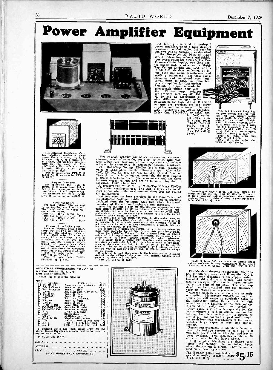
28 RADIO WORLD December 7, 1929
Power Amplifier Equipment
Polo Filament Transformer Only,four windings, consists of 50-60cycle" 110 v. winding, 2% v. at12 amps.. 2% v. at 3 amps., 5 v.at 2 amps. All windings, save pri-mary, are center -tapped (red). Size,4%" high x 39i," wide x 3" frontto back. Weight, 6 lbs. OrderCat. PFT @ $4.25.
[For 25 cycles order PFT-25 @$7.00; for 90 cycles order PFT-90@ $6. 25. ]
By -pals CondensersFor by-passing leads to
ground or C minus from 200 v.post or less, where current Is lessthan 10 m.a., 1 mfd. paper dielec-tric condensers are useful. OrderLV-1 @ $0.50 ea.
Filter CondensersFor high voltage filtration next
to the rectifier, use 1 or 2 mfd.The 2 mfd. makes the output volt-age a little higher.Order Cat. HV-1 (1,000 v.
DC, 550 v. AC) $1.76Order Cat. HV-2 (1,000 v
DC, 550 v. AC) $3.52
Filament -Plate -Choke BlockSan -e as Filament -Plate Supply,
except that two 50 henry chokes arebuilt in. Six windings: primary,110 v., 50-60 cycles; 2.5 v. at 12amps.; 2.5 v. at 3 amps.; 5 v. at2 amps.; 729 v. at 100 m.a.;choke Alt AC windings center -tapped (red), except primary. Con-nect either end of a choke to oneend of other choke for midsection.Order Cat. P-245-FPCH @..$10.00
[For 90 cycles order P-295-FPCH-40 @ $13.50.]
[For 25 cycles order P-245-FPCH-25 @ $14.50.]
At left is illustrated a push-pullpower amplifier, using a first stage ofresistance coupled audio, 280 rectifierand two 245s in push-pull, as describedin the November 2d issue of RadioWorld. Abounding volume and faithfultone reproduction are assured. The PoloFilament -Plate Supply, two Polo cen-ter -tapped audio chokes and a Multi -Tap Voltage Divider are used, with aQ 2-8, 2-18 Mershon condenser, an in-put push-pull audio transformer andauxiliary equipment. The total parts,including cadmium -plated steel sub -panel, come to $43.57 net, the bestpower amplifier for that modestamount. Provision is made forphonograph pickup plug inser-tion. Thirteen output voltagesare provided, including 300, 180,75, 50 and an assortment ofnine different voltages under50 available for bias. All A, B and Cvoltages are provided for the poweramplifier and for a tuner to be usedwith it employing 227, 224 or 228 tubes.Order Cat. P0 -245 -PA @ $43,57 net,
for 50-60 cycles,110 volts. (For25 cycles orderP0 -245 -PA -25$48.57. For 40cycles order PO -245 - PA - 40 @$46.07.]
Two rugged, expertly engineered wire-wouna enamelledresistors, mounted in series, one atop the other, with four-teen useful lugs, providing all necessary choice of voltageswithout the uncertainty of adjustable variable resistance.
The Multi -lap Voltage Divider has a total resistancevalue of 13,850 ohms, in the following steps: 3,000, 4,500,2,000, 800, 700, 600, 550, 500, 450, 400, 200, 100 and 50 ohms.With the zero voltage lug (at lower left) the total numberof useful lugs is fourteen. The resistance stated are thosebetween respective lugs and are to be added together toconstitute 13,850 ohms total.
A conservative rating of the Multi -Tap Voltage Divideris 50 watts, continuous use. The unit is serviceable in al(installations where the total current drain does not exceed125 milliamperes.
Extreme care has been exercised in the manufacture ofthe Multi -Tap Voltage Divider. It is mounted on bracketsinsulated from the resistance wire that afford horizontalmounting of the unit on baseboards and subpanels.
There long has been a need for obtaining any necessary interme-diate voltage. Including all biasing voltages, from a Multi -Tap Volt-age Divider, but each lug has to be put on individually by hand,and soldered, so that manufacturing difficulties have left the marketbarren of such a device until now.
The Multi -Tap Voltage Divider is useful in all circuits, includingPush-pull and single -sided ones, where the current rating of 125milliamperes is net seriously exceeded and the maximum voltage isnot more than 400 volts. If good ventilation is provided, this rat -in,; may be exceeded 15 per cent.
The expertness of design and construction will be appreciated bythose whose knowledge teaches them to appreciate parts finely made.
When the Multi -Tap Voltage Divider is placed across the filteredoutput of a B supply which serves a receiver, the voltages are inproportion to the current flowing through the various resistances.If a B supply feeds a receiver with two -stage audio amplifier, thelast stage a single -sided 245, then the voltages would be 250 maxi-mum for the power tube, 180, 135, 75, 50, 90, 35. 30. 25, 16, 10,6 and 3. By snaking suitable connection of grid returns the lowervoltages mry be used for negative bias or even for positive voltageon the plates.
If push-pull is used, the current in the biasing section is almostdoubled, so the midtsp of the power tubes' filament winding wouldgo to a lug about half way down.
Order Cat. MTVD at $3.95.- - -ACOUSTICAL ENGINEERING ASSOCIATES.143 West 45th St., N. Y. CRY -(Just East of Broad.eay.)
Please ship at once the following:Quan-
tity Cat. No. P0 -295 -PAO P0 -245 -PA -90 PO -245 -PA -25O PFPSO PFPS-400O PFTPFPS-25O PFT-40 PFT-25O P-245-FPCHO P-245-FPCH-40 P-245-FPCH-25 PDC PSCO MTVDO Q2-8. 2-18BO LV-1110 HV-1 HV-2
Product PricePaver amp. parts, 50-60 c. $43.57Same, 90 cycles 46.07Same, 25 cycles 48.57Fil. plate supply, 50-60 c. 7.50Same, 90 cycles 10.00Same. 25 cycles 12.00Fil. trans., 50-60 e. 4.25Same, 90 cycles 6.25Same, 25 cycles 7.00Power -filter block 10.00Same for 40 cycles 13.59Same for 25 cycles 14.50Double c. -t. choke 3.71Single choke 2.50Multi -tap volt. div. 3.95Mershon with bracket 5.15200 v., 1 mfd. by-pass cond. .50
1,000 v., 1 mfd. filter cond. 1.761,000 v., 2 mfd. filter cond. 3.52
Enclosed please find check-money order-for theabove. [Note: Canadian remittance must be by postal orexpress money order.]
Please ship C.O.D.
NAME
ADDRESS
CITY. STATE5 -DAY MONEYBACK GUARANTEE!
4Inimuquf1,11
111111:11:511H01111111110
.
=--
POLO.111YEERIMG lASOltaonmr,
..... Trea AOC aCo
.4\d4,'N, 411\.
Polo 245 Filament Plate Sup-ply (less chokes) has four wind-ings, all save primary center -tapped (red), is 4%" wide, 5"high, 4" front to back. Weight,9 lbs. Filament windings, 2.5 v.at 12 amps.. 2.5 v. at 3 amps.(tor 295 filaments). 5 v. at 2amps. for 280 rectifier, and 724v. @ 100 m.a., center -tapped.Order Cat. PFPS @ $7.50.
[For 25 cycles order Cat.PFPS-25 @ $12.00.]
[For 90 cycles order Cat.PFPS-40 @ $10.00.]
Center -tapped double choke, 125 m.a. rating, 30henrys in each section. Used for filtering B supplyor for a push-pull output impedance, where speakercords go directly to plates of tubes. Center tap is red.Order Cat. PDC @ $3.71.
Single 30 henry 100 m.a. choke for filtered output(where condenser is used additionally or for addedfiltration of a B supply. Order Cat. PSC @ $2.50.
The Mershon electrolytic condenser, 415 voltsDC, for filtering circuits of B supplies. Q 2-8,2-18 has four capacities in one copper casing:two of 8 mfd. and two of 18 mfd. The coppercase is negative. The smaller capacities arenearer the edge of the case. The vent capshould not be disturbed, and the electrolyteneeds no refilling or replacement.-Mershon electrolytic condensers are instantlyself -healing. Momentary voltages as high as1,000 volts will cause no particular harm tothe condenser unless the current is highenough to cause heating, or the high voltageis applied constantly over a long period.
High capacity is valuable especially for thelast condenser of a filter section, and in by-passing, from intermediate B+ to ground orC+ to C-, for enabling a good audio ampli-fier to deliver true reproduction of low notes.Suitably large capacities also stop motor -boating.
Recent improvements in Mershons have re-duced the leakage current to only 1.5 to 2mils total per 10 mfd. at 300 volts, and less atlower voltages. This indicates a life of 20years or more, barring heavy abuse.
In B supplies Mershons are always used"after" the rectifier tube or tubes, hencewhere the current is direct. They cannot beused on alternating current.The Mershon comes supplied with Itspecial mounting bracket. Order "5.15Q 2-8, 2-18 B

December 7, 1929 RADIO WORLD 29
L
What'sGoing to
HappenNext Month?
IT'S easy enough to find out. If you are a radio dealer,jobber, service -man or radio salesman, we will tell you
what to do in January and the months to follow. If youare not engaged in the business of radio merchandising,please do not communicate with us. Send us $2.00, alongwith your business card or letterhead, proving that youare a radio business man, and we will send the next twelveissues of "RADIO" to you, starting with the great 126 -
page December number. Each month "RADIO" tells theradio merchant how to make more money SELLINGRADIO. More than 35,000 radio dealers are now reading"RADIO." Subscriptions at the $2.00 rate will be
accepted during the month of December. Thereafterthe rate is $5.00 per year. Your money cheerfully re-funded if you are not entirely convinced that "RADIO"is worth its weight in gold.
Your Letter Head or Business Card Must Accompany
Your Subscription. No Subscription Accepted
From People Who Are Not in the Radio Business
Publishers of "RADIO"415 Lexington Avenue New York, N. Y.307 No. Michigan Avenue, Chicago, Ill.
R.W.I
428 Pacific Bldg., San Francisco, Cal. I86 St. Botolph Street, Boston, Mass.
(Send subscription to office nearest you.) I
HERE is $2.00 in full payment for a one year suscription to "RADIO" starting Iwith the December issue. My business card or letterhead, proving that I ama radio merchant, is attached to this order. I
Name
Street & No.
City State
I am a 0 Dealer El Jobber 0 Service Man 0 Salesman(Please be sure to state which)

30 RADIO WORLD December 7, 1929
Horn Unit $2.25
This unit is pre-eminent for horn -type speakerssuch as the exponential horns or other long tonetravel horns. The faintest word from a "whispering tenor" or the tumultuous shout of the crowdor highest crescendo of the band is brought outclearly, distinctly. Stands up to 450 volts without filtering. Works right out of your set'spower tube, requiring no extra voltage sourceStandard size nozzle and cap are die-cast aluminum, one piece, with milled platinum -likefinish. The casing is full nickel, of highest posBible polish. Works great from AC set, batteryset or any other set, push-pull or otherwise.
For Portable UseThis unit can be used in a portable without an.horn attached and will give loud reproductionOrder Cat. 225, with 4% ft. cord attached . .
(Shipping weight, 2 lbs.) $2.25
Air -Column Horn8 -ft. tone travel molded wood horn (less unitNo. 225) is obtfinable already mounted inbaffle box. Outside overall dimensions of bathebox, 21/s" high, 18" wide, 15" front to backShipping weight, 27 lbs. Order Cat. 596 @ $8.00Acoustical Engineering Associates,145 W 45th St.. N. Y. City (lust E. of Bway).
Please ship C. 0. D.0 Cat. No. 225 W $2.25 0 Cat. No. 596 t $5.0'
Name
Address
Gib State
FIVE-DAY MONEY -BACK GUARANTEE
Slightly higher west of the
List price
$15.00Rockies
PHONOGRAPHMUSIC
is at its bestwith the
Super PhonovoxPlays records electrically through your radio with amazing tonerealism and volume. New combination switch and volume control(with special adapter for screen grid tubes) switches instantly fromradio to records without changing any connection. English 36%Cobalt Magnets provide extreme sensitivity. Hear it at your dealers.Two new low impedance models now available.
PACENT ELECTRIC CO., INC., 91 SEVENTH AVE., N. Y.Pioneers in Radio and Electric Reproduction for over 20 years
Manufacturing Licensee for Great Britain and Ireland: Igranic Electric Co., Ltd., Bedford, Eng.Licensee for Canada: White Radio Limited, Hamilton, Ont.
ILVEIP10111111,114When it comes to making sick radios well, orgood radios better, just remember-
CLAROSTATthe name of a line of products dedicated to bet-ter radio results.Clanostat Mfg. Co., 291 N. 6th St., B'klyn, N. Y.
LYNCHTUBADAPTAFor Better TONEList Price.. $2.50Improves reception and prolongs life of ex-pensive power tubes. Gskd in last audio stage.Write for descriptive circular and completecatalogue Lynch Guaranteed Radio Products.LYNCH MFG. CO., Inc.. 1775 B'way, N. Y.
SUBSCRIBERS? Look at the ExpirationDate on Your Wrapper
Please look at the subscription date stamped on your last wrapper, and if that dateindicates that your subscription is about to expire, please send remittance to coveryour renewal. Please give our subscription department two weeks to make changesin expiration dates, street addresses, etc.
In this way you will get your copies without interruption, and keep your filecomplete.
SCREEN GRID TUNER
The moat sensitive tuned radio frequency tuner so far developed, theSIB -23 is long on distant reception, and penetrates seemingly unsur-mountable barriers to reception. On the MB -29 the stations come Inno matter where you are. The MB -29, designed by James Millen andProf Glen H. Browning, is the choice of the most discriminating.It is designed only for AC operation, uses four stages of screen gridBF and a power detector (227). Use 135 to 180 volts on the detector.Testimonials from radio's hardest -boiled experts prove this Is thecircuit of circuits. Buy the parts and find fullest radio delight.Tou will be sure nobody else has a tuner as good as yours, unlesshe too has an MB -29. Complete component parts for National ScreenGrid Tuner MB -29, mounted on frostedaluminum chassis, including rainbow modern - $40000idle drum dial HC. Order catalog No.MB -29-K, list price, less tubes, $69.50Tour price
SUBSCRIPTION DEPARTMENTRADIO WORLD, 145 West 45th St., N. Y. City
B-29The National Velvetone Push -PullPower Amplifier (shown at right)consists of an AC -operated filament -plate supply, with two stage trans-former audio amplifier and outputtransformer built in. Made only for110-V., 50-60 cycles. Sold only incompletely wired form, licensed underRCA patents.The new Power Amplifier has beendeveloped and built to get the verymost out of the MB -29. It is a com-bination power supply and audio ampli-fier, using a 280 tube for a rectifier,one stage of transformer audio with a227 tube and a stage of push pullamplification with two 245s. It furnishesall power for itself and for the MB -29,as we'll as the audio channel. Ordercatalog PPPA, list price, completelywired and equippedwith phonographjack, (less tubes)$97.50. Your price. $5500
Push -Pull Amplifier
View of National Velvetone Push -Pull Power Amplifier.an expertly made A, B and C supply and audio amplifier.
producing marvelous tone quality.
GUARANTY RADIO GOODS CO.143 WEST 45TH STREET NEW YORK CITY

December 7, 1929 RADIO WORLDBRILLIANT, NEW0.1 MA, $5.95
Here is a 0-1 milliammeter, accurateto plus or minus 1% clearly legible totwo -one hundredths of a milliampereat any reading (20 microamperes).This expertly made precision instru-ment is offered at the lowest price sofar for a 0-1 ma. Order Cat. FO -1at $5.95. C. 0. D. orders accepted.
Guaranty Radio Goods Co.143 West 45th Street,
New York City
AERIAL TUNERImproves Your Reception
caa
Remove aerial lead from set. Connect aerialinstead to one of the binding posts of the AerialTuner Connect the other binding post of theAerial Tuner to antenna post of your set. Thenmove the lever of the Aerial Tuner until any weakstation comes in loudest. The lever need not bemoved for every different frequency tuned in.The Aerial Tuner acts as an antenna loadingcoil and Outs the antenna's frequency at anyfrequency in the broadcast band that you desireto build sin.
GUARANTY RADIO GOODS CO.143 West 45th Street
New York City(Just East of Broadway)
10111%.%"10%110111t1101%11011%.%1011%0
NATIONALMODERNISTIC PROJECTION DIAL
WITH RAINBOW FEATURE
Modernize the appearance of your receiver by installingthe brilliant new National dial, with color wheel built in,vo that as you turn the dial knob one color after anotherfloods the screen on which the dial numbers are read. Onthis screen the numbers are projected, so that YOU get thesame dial reading from any position of the eye. This isjust what DX hunters want-laboratory precision of dialreading.
The escutcheon is of modernistic design. The VelvetVernier mechanism drives the drum superbly.
Order today. Remit with order and we pay cartage.Shipments day following receipt of order.
GUARANTY RADIO GOODS CO.,143 W. 45th St., N. Y. City (Just E. of B'way)
Enclosed please find $3.13 for which please send medial marked below:0 Cat. HC6, National modernistic drum dial, with color
wheel built in, pilot bracket, 6 -volt pilot lamp forstorage battery or A eliminator sets; hardware; instruc-tions $3.13
CI Cat. NC21/2. same as above, but with 2',4 -voltAt' pilot lamp
0 Order C.O.D. and I pay cartage.
NAME
ADDRESS
CITY STATE
RADIO WORLD'S BOOK SERVICEhas been found of great value not onlyby radio fans, constructors, etc., but alsoby radio and other technical schoolsthroughout the country. See the radiobooks advertisements in this issue.
LACAULT'S BOOK"Super -Heterodyne Construction and Operation,"giving the master's most masterful ..,
of the theory, performance and construction ofthis fascinating type of circuit, is a necessityto every serious radio experimenter. Mors than100 pages and more than 50 illustrations. Buck-ram cover. This book by R. E. Lacault, FREEIf you send $1.00 for an 8 -weeks subscriptionfor Radio World. Present subscribers may acceptthis offer. Subscription will be extended.
RADIO WORLD 145 W. 45th St., N.Y. Citylust East of B'way
NATIONALVelvet B Eliminator $16.1311$ Volts (28$ Tubs Free)
Latest Model National Velvet -B, Type 8580.handsome crackle finish black metal casing, for usewith sets up to and including eta tubes. Input105-120 volts AC, 50 to 60 cycles. Output. 180volts maximum at 95 milliamperes. Three variableoutput Intermediate voltages. (Det.. RP, AF)Eliminator has excellent filter system to eliminatebum, Ineluding SO henry choke and 1$ ofdMershon condenser. No motorboating I(Eliminator Licensed under patents of the RadiiCorporation of America and associated companies. 1
Guaranty Radio Goods Co.143 W. 45TH STREET
(Just East if Broadway)NEW YORK CITY
New Junior Model
POLO UNIT $4The famous twin magnet principle fordouble sensitivity, large magnets for greatflux, permanently adjusted armature, allare in the new junior model Polo Unit.Weight, 244 lbs. Stands 150 volts unfil-tered. Stands up to 250 push-pull filtered.Works any output tube, power or other-wise. Supplied with 10 -ft. cord. Order.,nit now. Five-day money -back guarantee.Shipped C. 0. D. if desired.
Acoustical EngineeringAssociates
143 West 45th StreetNew York City
(Just East of Broadway)
RADIO WORLDand "RADIO NEWS"
BOTH FOR $7ONE YEAR (g). .00
You can obtain the two leading radio techaieal maga-zines that cater to experimenters, service men and students,the first and only national radio weekly and the leadingmonthly, for one year each, at a saving of $1.50. Theregular mail subscription rate for Radio World for seeyear, new and fascinating copy each week for 52 weeks,is $6.00. Send 1n $1.00 extra, get "Radio Mawr shotfor a year-a new issue each month for twelve monthsTotal, 64 issues for $7.00.
0 If renewing Radio World subscription, put erosasquare.RADIO WORLD, 145 West 45th Street, New Tort. N. 1.
Quick Action Classified AdsRadio World's Speedy Medium for Enterprise and Sales
10 cents a word - 10 words minimum - Cash with OrderEDISON STORAGE BATTERIES -100 volts$6.50; l44 Horsepower Alternating Motors $7.00.Hoffmann Electrical Shops, 904 North Fifth,Philadelphia, Pa.
"MATHEMATICS OF RADIO."-A great helpto everybody interested in radio. $2 postpaid.Radio World, 145 W. 45th St., N. Y. City.
RECENT NUMBERS OF RADIO WORLD, for1929, 15c per copy. Any 7 copies for $1. RadioWorld, 145 W. 45th St., N. Y. City.
TELEVISION and all about it in "A B C ofTelevision," by Raymond Francis Yates. $3 post-paid. Radio World, 145 W. 45th St., N. Y. City.
"EVERYBODY'S AVIATION GUIDE." By Maj.Page. $2 postpaid. Also "Modern Aircraft" bysame author. $5. postpaid. Radio World, 145 W.45th St., N. Y. City.
EXPERIENCED RETAIL SALESMENDAVEGA DIVISION AND CITY DIVISION OFTHE ATLAS STORES CORPORATION IS NOWIN NEED OF SEVERAL HIGH-POWERED EX-PERIENCED RETAIL RADIO SALESMENWHO WOULD LIKE TO ASSOCIATE THEM-SELVES WITH THE LIVEST RETAIL RADIOSALES ORGANIZATION IN THE UNITEDSTATES-A COMPANY THAT PERMITS ITSMEN TO EARN IN SALARIES AND COMMIS-SIONS UNUSUALLY LARGE WEEKLY IN-COMES. PLUS UNLIMITED OPPORTUNITIESFOR PROMOTION. INTERVIEWS WILL BETREATED IN CONFIDENCE. SEE ED. LEVY,SALES MANAGER FOR THE EASTERNDIVISION, DAVEGA, INC., 114 EAST 23STREET, NEW YORK CITY.
EVERYTHING IN RADIOAt attractive Prices Sets or parts
Orders shipped exactly as ordered. Promptservice. Write for prices. Inquiries invited.Send your address.ALL RADIO CO., 417 North Clark St., Chicago
BE SURE TO READ the advertisement onanother page of this issue about the HB Compact.Guaranty Radio Goods Co., 143 W. 45th St.,N. Y. City.
TWO FOR ONE. Radio World for 52 weeks andRadio News twelve months at the combinationrate of $7. Radio World, 145 W. 45th St., N. Y.
"MODERN AIRCRAFT," By Maj. Page. $5.postpaid; and "Everybody's Aviation Guide," ByMaj. Page, price $2. postpaid. Latest and bestup-to-date aviation books. Radio World, 145W. 45th St., N. Y. City.
"A B C OF AVIATION." By Maj. Page. $1.00postpaid. Radio World, 145 W. 45th St., N. Y.City.

RADIO WORLD December 7, 1929
THREE CHRISTMAS GIFT BOOKS FOR SERVICE MEN!"Trouble Shooter's Manual""Mathematics of Radio"
The niost popular and fastest -selling book in radio today. Wiring dia-grams of commercial receivers are contained in this outstanding book.
A sure route to a good grasp on radio technique. Radio theory outlined so thatanybody can understand it.
"Testing Units for Service Men" Circuits and Methods of Testing Equipment, particularly use ofindividual meters and of meters united in combination testers.
These Three Books by John F. Rider Constitute an Outstanding Asset to All Possessors!"Trouble Shooter's Manual"is the first comprehensive volume devoted ex-clusively to the topic. The 240 pages include200 illustrations devoted to wiring diagrams offactory -made receivers, besides other illustra-tions. It is not only a treatise for service men,telling them how to overcome their most seriousproblems, and fully diagramming the solutions,but is a course in how to become a service man.
This book is worth hundreds of dollars toany one who shoots trouble in receivers -whether they be factory -made, custom-built orhome-made receivers.
Besides 22 chapters covering thoroughly thefield of trouble shooting, this volume containsthe wiring diagrams of models, as obtaineddirrect from the factory, a wealth of hithertoconfidential wiring information released for thefirst time in the interest of producing betterresults from receivers. You will find these
diagrams alone well worth the price of the book. The wiring diagrams are of newand old models, of receivers and accessories and as to some of the set manufacturers,all the models they ever produced are shown in wiring diagrams! Here is the listof receivers, etc., diagrams of which are published in this important and valuablebook:
Wiring Diagrams of All These ReceiversR. C. A.
60, 62, 20, 64, 30, 105, 51,16, 32. 50, 25 A.C., 28 A.C..41, Receptor S.P.U., 17, 18,33.
FEDERALType E series filament, TypeE series ( filament, Type Dseries filament, Model B.Model H.
ATWATER-KENT10B, 12. 20, 30, 35, 48, 32,33, 40, 38, 36, 37. 40, 42,52, 50, 44, 43, 41 power unitsfor 37, 38, 44, 43, 41.
CR OHL EYXJ, Trirdyn 3R3. 601, 401.401A, 608, 704, B and C sup-ply for 704, 704A, 704B, 705,706.
STEWART-WARNER300. 305, 310, 315, 320, 325,500, 520, 525, 700, 705, 710,715 720. 530, 535, 750, 801,802, 806.
GREBEMill, MII2, synchrophase 5,synchrophase .ACI3. synchrophaseAC7. Deluxe 428.
PH ILCOPhilco-electric, 82, 86.
K)Ls ER4 -tube chassis used in 6 tubesets, tuning chassis for 7 tubesets, power amplifier, 7 tubspower pack and amplifier, Ctube power pack and amplifier,6 tube power pack and ampli-fier, rectifier unit K-23,
ZENITH39, 39A, 392, 392A, 40A.35PX, 35APX, 352X, 852APX,37A, 35P, 35AP, 352P, 352AP,31P. 342P, 33, 34, 35. 35A,342. 352, 352A. 362, 31, 333,353A, power supply ZE17,power supply ZE12.
MAJESTIC70. 70B, 180, power pack 7BP3,7P6, 7P3 (old wiring) 8P3,8P6.7BP6.
FRESHMANMasterpiece, equaphase. G.0-60-S Dower supply, L andLS, 015, Q, K60 -S powersupply.
STROMBERG -CARLSON1A, 2B, 501. 502, 523, 524,635, 638, 403AA power plant,404 RA power plant.
All -AMERICAN6 tube electric, 8 tube 80, 83,84, 85, 86, 88, 6 tube 80, 61.62, 65, . 66, u and 8 tube A.C.power pack.
DAY FANOEM7, 4 tube, 5-5 tube 1925model, Day Fan 8 A.C., powersupply for 6 tube LC.. Bpower supply 5524 and 5525.motor generator and fib:4r, 6tube motor generator set, 6tube 110 volt D.C. set. 6 tube32 volt D.C. set.
FADA50/80A receivers, 460A, Fade10. 11, 30. 31, 10Z, 11Z, 30Z,31Z, 16, 17, 32, 16Z, 32Z, 19.!IA special, 192A -192S and192BS units, BSC& 480A, andSF 50/80A receivers, 460A re-ceiver and R60 unit, 7 A.C.receiver. 475 UA or CA andSF45-75 UA or CA, 50, 70,71, 72, C electric unit forspecial and 7 A.C. receivers.ABC 6 volt tube supply, 86Wand 82W. E180Z power plantand E 420 power plant.
FREED EISEMANNNR5, F1.18, NR -0, 470, NR57,457, NR11, NR80 D.C.
COLONIAL26, 31 LC., 31 D.C.
WORKRITE8 tube chassis, 6 tube chassis.
AMRAD70, 7100, 7191 power unit.
SPARTONA.C. 89.
MISCELLANEOUSDeForest F5, DIO, D17. SuperZenith Magnavox dial, Ther-miodyne. Grimes 4DL inverseduplex, Garod neutrodYne.Garod EA, Ware 7 tube, Waretype T. Federal 102 special,Federal 59, Kennedy 220,Operadio portable, SleeperRX1, Amrad inductrol.
HERE ARE THE 22 CHAPTER HEADINGSServive ProcedurePractical Application of AnalysisVacuum TubesOperating SystemsAerial Systems"A" Battery EliminatorsTroubles in "A" EliminatorsTrouble Shooting in "A" Eliminators"B" Battery EliminatorsTroubles in "B" Battery Eliminators
TREATISE OH
TESTING UNITS
FOR SERVICE MEN
I
Trouble Shooting in "B" Battery EliminatorsSpeakers and TypesAudio AmplifiersTrouble Shooting in Audio AmplifiersTroubles in Detector SystemsRadio Frequency AmplifiersTrouble Shooting in RF AmplifiersSeries Filament ReceiversTesting, and Testing DevicesTroubles in DC SetsTroubles in AC Sets
"Testing Units for Service Men."A 48 -page, liberally illustrated book on testingunits and circuits. Tells what equipment a serv-ice man should have and how to use it mosteffectively and quickly. Rapidity of operation isone of the points stressed throughout this valu-able book, as a service man's time is his chiefstock in trade.
CONTENTSTube Reactivator and VoltagesCalibrated Vacuum Tube BridgeGeneral Utility Tube TesterAC -DC Receiver TesterEliminator TestersSignal Generator for Receiver TestingOscillatorsCathode Ray 0 sei llographIndicating SystemsTube VoltmetersMeasurement of Inductance, Impedance, Capac-ity. DC ResistanceMulti -Range MetersService Station Test Bench
"Mathematics of Radio"TABLE OF CONTENTS:
OHM'S LAW.RESISTANCES: Basis for resistance variation, atomic
structure, temperature coefficient, calculation of re -vistance variation, expression of ampere, volt andOhm fractions, application of voltage drop, platecircuits, filament circuits, filament resistances, gridbias resistances.
DC FILAMENT CIRCUITS: Calculation of resistances.AC FILAMENT CIRCUITS: Transformers, wattage
rating, distribution of output voltages, voltage re-ducing resistances, line voltage reduction.
CAPACITIES: Calculation of capacity, dielectric con-stant condensers in parallel, ondensers in series,
in parallel, in series, utilityof parallel condensers, series condensers.
VOLTAGE DIVIDER SYSTEMS FOR B ELIMI-NATORS: Calculation of voltage divider resistances,types of voltage dividers, selection of resistances,wattage rating of resistances.
INDUCTANCES: Air core and iron core, types of aircore inductances, unit of inductances, calculation ofinductance.
INDUCTANCE REQUIRED IN RADIO CIRCUITS:Relation of wavelength and product of inductanceand capacity, short wine coils, coils for broadcastband, coupling and mutual inductance, calculationof mutual inductance and coupling.
REACTANCE AND IMPEDANCE: Capacity react-ance, inductance reactance, impedance.
RESONANT CIRCUITS: Series resonance, parallelresonance. coupled circuits, bandpass filters forradio frequency circuits.
IRON CORE CHOKERS AND TRANSFORMERS:Design of chokes, core, airgap, inductance, reactance,wimp,eindagnsee, transformers, half wave, full ways
VACUUM TUBES: Two element filament type, elec-tronic, emission, limitations, classifications of fila-ments, structure, two element rectifying tubes,process of rectification, tungar. bulb.
THREE ELEMENT TUBES: Structure of tube, de-tector, grid bias, grid leak and condenser, amplifiers.tube constants, voltage amplification, resistancecoupling, reactance coupling, transformer coupling,variation of impedance of road with frequency, tunedPlate circuit.
POWER AMPLIFICATION: Square law, effect ofload, calculation of output power, undistorted outputpower, parallel tubes, push-pull systems, plateresistance.
GRAPHS AND RESPONSE CURVES: Types ofpaper, utility of curves, types of curves, significanceof curves, voltage amplification, power amplification,power output, radio frequency amplification.
MULTIPLE STAGE AMPLIFIERS: Resistance coup-ling, reactance coupling, tuned double impedance am -plification, underlying principles, transformer coup -ling, turns ratio, voltage ratio, tyes of cores, latecurrent limitation, grid current limitation.
ALTERNATING CURRENT TUBES: Temperature va-riation hum, voltage variation hum, relation betweengrid and filament, filament circuit center tap, typesof AC tubes.
SCREEN GRID TUBE: Structural design, application,amplification associated tuned circuits, radio fre-quency amplification, audio frequency amplification.
rt- RADIO WORLD. 145 West 45th St., New York, N. V.
Enclosed pleaseti(n.Idu:st East of Broadway)
63.50 for which please send me postpaid "Trouble Shooter's Manual" (Cat.TSM), by John F. Rider, 240 pages, 814111", more than 200 illustrations,including wiring diagrams of commercial receivers as advertised; imitationleather cover, gold lettering. $2.00 for which please send me postpaid "Mathematics of Radio" (Cat. MOB),by John F. Rider, 128 pages, 8%111", 119 illustrations, flexible cover. 61.00 for which please send me postpaid "Treatise on Testing Units for ServiceMen" (Cat. TII). by John F. Rider. 43' pages, 61419%".If ordering C.O.D., put cross in this square.
11.
NAME
ADDRESS
CITY STATE[Canadian remittances must be made by postal or express money order.]