i the cardington m author fire tests i - aisc.org the cardington fire tests gerald newman ... an...
TRANSCRIPT
I w
I s~
I I I I I I I I I I I I I I I I I
The Cardington Fire Tests
Gerald Newman
Author
Mr. Gerald Newman has worked in structural lire engi
neering for 20 years starting with single story buildings and fire protection materials and moving towards multi·story buildings. He is a member of a number British and European fire commiffees dealing with fire testing and structural fire engineering. He was the main author of the British Standard, 8S5950·8, Code of Practice for fire resistant deSign and has recently been appointed to the project team for the Eurocode, EC4-1-2 dealing with composite construction. His main activity in the last three years has been as a consultant to the research that the has been carried on the full scale fire testing of an eight-story office building at BRE, Cardington, in the United Kingdom. The test program has been completed but work continues on the development of design guidance based on observed behavior and computer modeling
Summary
This paper briefly reviews the structural fire engineering
methods available to engineers in the United Kingdom and Europe and then gives a description of some full·scale fire tests carried out at Cardington (UK) in an old, very large, airship hangar.
It is accepted in the UK and Europe that, in many cases, structural response in fire may be calculated rather than be evaluated in a fire resistance test. Simple methods exist which predict the results of a fire resistance test taking into account such things as applied load, span and support conditions. Examples are given of beam and column elements which can be used without applied fire protection to achieve up to 180 minutes fire resistance.
The behavior of structures in actual fires has shown that the elemental approach inherent in national building regulations may
28-1
be conservative. During 1995 and 1996 structural response was studied in a series of fire tests in the UK in a specially constructed eight story steel-framed building. The largest test covered a floor area in excess of 300 m2• This paper reviews the tests and describes in some detail the behavior in one of the larger tests.
Following on from the tests, design guidance is being developed. This will be based on analysis of the test using finite element methods. It is hoped that simple design guidance can be developed which will enable most of the steel floor beams to be used without applied protection and without the necessity to use complex programs. It is expected that all columns will require protection to control potential damage and to ensure overall frame stability. Some examples are given of possible forms which the design guidance may take.
The research has been financed by British Steel, the United Kingdom Government (DETR) and the European Coal and Steel Community (ECSC).

I I I I I I I I I I I I I I I I I I
28-2 I

I ~ 1 1/1
I I I I I I I I I I I I I I I I I
THE CARDINGTON FIRE TESTS Gerald Newman, Ian Simms et al Steel Construction Institute, Ascot, UK
1 INTRODUCTION In September 1996 a programme of fire tests 'li was completed in UK at the Building Research Establishment 's, Cardington Laboratory. The tests were carried out on an 8 storey composite steel framed building which had been constructed as a typical multistorey office building.
The purpose of the tests was to investigate the behaviour of a real structure under rea l fire conditions and to collect data that would allow computer programs, which are capable of analysing structures in fire, to be verified. The ultimate aim of the Cardington research is to improve and rationalise the design of structures to resist fire whilst still achieving agreed levels of safety. This Will almost certainly Involve using less applied protection and possibly greater use of active safety measures.
Before describing the tests and the outcome It IS Important to put the tests Into context. In UK and Europe designing structures to have fire resistance is becoming more common. UK has had BS5950-8, Code of practice for fire resistant design''', since 1990 and the Structural Eurocodes have recently been published. There are also differences in fire resistance testing methods between Europe and North America and differences in fire regulations .
2 ASPECTS OF THE EUROPEAN FIRE "SCENE" The Broadgate Fire
In 1990 a fire developed In a partly completed 14 storey office block on the Broadgate development in London"'. Fire temperatures were estimated to be over 1 OOooC. Following the fire structural elements covering an area of approximately 40 x 20m were replaced, but importantly no structural failure occurred and the Integrity of the floor slab was maintained during the fire (Figure 11. The direct fire loss was in excess of (25M , of which less than (2M was attributed to the structura l frame and floor damage, the other costs resulted from smoke damage.
Figure 1 Deformed structure at 8roadgate
28-3

The design of the Cardington tests was influenced by the Broadgate fire. Following this fire it could be seen that some of the elements had lost their load carrying capacity during the fire. However, the structure performed well with no signs of collapse. It was clear that the composite fl,?or had a major Influence on the overall stability of the structure, acting as a diaphragm or membrane distributing loads from weakening members.
Fire resistance testing
In UK and Europe all tests on structural elements are loaded tests. Failure is based on a deflection limitation. The temperature of any part of an element is not relevant. Some types of steel beam are used in UK based on flange temperatures in excess of 750°C. This would not be permitted in North America where normally failure is based on a maximum temperature and IS not related to structural failure. Differences also exist in restraint conditions. Restrained tests are the norm in North America but are largely unheard of in Europe. In this paper brevity dictates that a long discussion on the pros and cons of boundary conditions in fire resistance testing is not possible.
Fire regulations
In England and Wales periods of fire resistance such as 30, 60 or 90 minutes are not mandatory. The Building Regulation states that "the building shall maintain its stability for a reasonable time" . Fire resistance periods are recommended and 99% of all buildings are built to the recommended periods. However, the flexibility implied in the basic regulation opens the door to other 'fire engineering' approaches .
Design codes
BS 5950-8, Code of practice for fire resistant design , published in 1990, was one of the first structural fire deSign codes in the World. It contains both general principles for structural fire design and specific deSign Information for some common cases. BS 5950-8 contains information on composite and noncomposite steel construction. During, 1999 the equivalent Eurocodes will be published in the UK. EC3-1-2'41 covers the fire resistant design of non-composite and EC4-1-2'S1 covers the design of steel and concrete composite structures.
All three Standards present design rules for elements which are either based on the analysis of a number of fire tests, or are based on some mathematical model of structural behaviour. These codes are based on the assumption that the fire is considered to be an accident which will rarely occur. At the time of a fire the building is not likely to be loaded to its design limit and some reductions from the normal, in-service, design loads are allowed.
All design codes contain information on the strength of materials. Design methods in fire are generally based on the normal 'cold' methods but utilise reduced material properties at elevated temperatures.
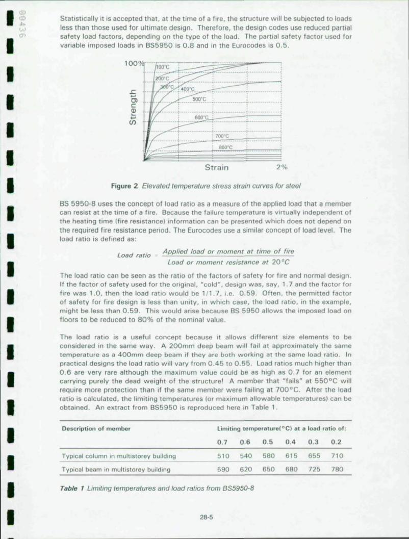
All materials lose strength and stiffness at high temperatures. The commonly used grades of structural steel and concrete lose about half their strength at 600°C. The elevated temperature stress-strain curves for structural steel are presented in Figure 2.
Structural elements are designed at normal temperatures with a safety factor on strength of about 2, so at 600 ° C they could have lost their Initial reserve of strength and they may fail. However, in any practical design, the safety factor may vary from about 1.6 to 2.5. This is because the initial design may be based on a deflection limit rather than strength. The failure temperature in fire will normally vary from about 550°C to 700°C. In some circumstances this variation can be economically significant, allowing savings to be made in fire protection costs.
28-4
I I I I I I I I I ' I I I I I I I I I I
I ~
I I I I
I I I I I I I I I I I I
Statistically It IS accepted that , at the time of a fire, the structure will be subjected to Joads Jess than those used for ultimate design. Therefore, the design codes use reduced partial safety load factors, depending on the type of the load. The partial safety factor used for variable Imposed loads in BS5950 IS 0.8 and in the Eurocodes IS 0.5.
.......... ........
---~- .... ---i-
... _ ... __ _ ;':'_:;"~"~' _-,l~7:::0:;O .;:;~.,,_"' .. "' .. "' .. i .. = .. :: .. ::.-:: .. :::.:-: .. ~. ~ .; .... ::"u~ : 800 C ",_ ............. ,
Strain 2%
Figure 2 Elevated temperature stress strain curves for steel
BS 5950-8 uses the concept of load ratio as a measure of the applied load that a member can resist at the time of a fife. Because the failure temperature IS virtually Independent of the heating time (fire resistance) Information can be presented which does not depend on the reqUIred fire resistance period. The Eurocodes use a similar concept of load level. The load ratio is defined as:
Load ratio Applied load or moment at time of fire
Load or moment resistance at 20°C
The load ratio can be seen as the ratio of the factors of safety for fire and normal deSign. If the facto r of safety used for the original, "cold", deSign was, say, 1.7 and the factor for fife was 1.0, then the load ratio would be 111 .7 , i.e. 0.59 . Often , the permitted factor of safety for fife design is less than unity, in which case, the load ratio, In the example, might be less than 0 .59. ThiS would arise because BS 5950 allows the Imposed load on floors to be reduced to 80% of the nominal value.
The load ratio is a useful concept because It allows different size elements to be considered In the same way. A 200mm deep beam will fall at approximately the same temperature as a 400mm deep beam if they are both working at the same load ratio. In practical designs the load ratio Will vary from 0.45 to 0.55 . Load ratios much higher than 0.6 are very ra re although the maximum value could be as high as 0.7 for an element ca rrying purely the dead weight of the st ructure! A member that "fails" at 550°C will require more protection than If the same member were failing at 700°C. After the load ratio IS calculated, the limiting temperatures (or maximum allowable temperatures) can be obtained. An extract from BS5950 is reproduced here In Table 1.
Description of member
Typical column In multlstorey bUilding
TYPical beam in multistorey bUilding
Limiting temperature( OC I at a load ratio of :
0 .7 0 .6 0 .5 0.4 0.3
510 540 580 615 655
590 620 650 680 725
0.2
710
780
Table 1 Llmitmg temperatures and load ratios from 8S5950-8
28·5

Using the concept of load ratio and limiting temperature it is possible to show that some sections do not require fire protection or that it is possible to use reduced amounts of fire protection .
Unprotected steel
In UK and Europe the use of unprotected steel for fire resistance resistances up to 60 minutes (and sometimes 90) is common'SI. Some types of unprotected beams and columns are illustrated in Figure 3. Exposed flange temperature in all cases will be in excess of 750°C.
Unprotected beams
._. -, ....
Partially encased beam· up to 120 minutes fire resistance
ASB with deep decking 60 mlns fire resistance
Unprotected columns
Blockfilled column 30 mins fire resistance
Partially encased composite column 120 minutes fire reSistance
Figure 3 Types of unprotected steel beams and columns
3 THE CARDINGTON FIRE TESTS The Cardington fire tests were conducted in an eight story office building deSigned to be a typical example of the type of braced structure and load levels which are commonly found in the UK. On plan the building covered an area of 21 m x 45m with an overall height of 33m. There were 5 equally spaced bays along the length of the building and three bays 6m. 9m and 6m across the width. The frame had three braced cores. one central 9m x 2.5m lift core and two 4m x 4.5m stairwells at either end of the structure. The building under construction is shown in Figure 4. The beams were designed as simply-supported acting compositely with the floor slab. The composite flooring system consisted of steel decking with grade 35 concrete and A 142 mesh . The depth of the slab was 130mm. To comply with UK building regulations this type of building would normally have 90 minutes fire resistance. Fin plates were used for the beam to beam connections and flexible end plates for the beam-to column connections. The structure was loading using sandbags distributed over each floor to simulate typical office loading .
The research programme was in two parts. One project was funded by British Steel and European Coal and Steel Community (ECSCI and one project was funded by the UK Government via the Building Research Establishment (BRE). The organisations involved included British Steel. BRE, Sheffield University, TNO (The Netherlandsl. CTICM (France) and The Steel Construction Institute.
2B-6
I I I I I I I I I I I I I I I I I I I I

I I I I I I I
I I I I I I I I I
Figure 4 The test bUilding under construction
The two programmes of tests IECSC and BRE) took place between January 1995 and July 1996 and were designed to be complementary. Where possible, lessons from one test influenced the details of the follOWing tests. Table 2 summaries details of the 6 large scale tests which were conducted and Figure 5 shows the locations within the frame were these tests took place. Test one Involved a single beam and the surrounding floor slab which was heated by a purpose bUilt gas fired furnace . Test 2 was conducted on a plane frame spanning across the building at one floor level which included primary beams and associated columns. Tests 3 , 4 and 5 Involved compartments of various sizes. The columns In these tests were generally protected up to the underSide of the floor slab and the beams and floor slab were left unprotected . The structure was subjected, in each case, to a natural fire fuelled by timber Cribs. The last test was a demonstration uSing furniture typically found In modern offices.
A diSCUSSion of all the tests would be somewhat long so, thiS paper concentrates on the restrained beam test and the office demonstration test.
Test Sponsor Description Floor area 1m· ) Location
ECSC Restrained beam 24 level 7
2 ECSC Plane frame 53 IO\l'el4
3 ECSC 1 SI Corner 76 10\1'012
4 BRE 2nd Corner 54 level 3
5 BRE Large compartment 340 level 3
6 ECSC large compartment (office) 136 level 2
Table 2 Summary of the test programme
26-7

3.1
45m
3
5
21m
2
4 6
Figure 5 Test locations
1. Restrained beam test (ECSC) 3. Corner test (ECSC) 5. Large compartment (BRE)
Test 1, Restrained Beam
2. Plane frame test (ECSC) 4. Corner test (BRE) 6. Simulated office (ECSC)
The restrained beam test was carried out on the seventh floor of the building used a purpose built gas fired furnace which heated the beam over the middle B.Om of its 9.0m span . This permitted the connections to remain as close as possible to ambient temperature . Although, previous research has shown that it is not necessary to fire protect the voids between the beam and the steel decking, the voids were filled in this case in order to reduce the thermal gradient and simplify the computer modelling. The heated steel beam and the surrounding structure were extensively instrumented using strain gauges, position sensors, inclinometers and thermocouples. The maximum displacement and temperature of the beam are shown in Figure 6 .
Local buckling occurred in the bottom flange of the beam at both ends (Figure 7) . In addition to this the bottom flange had also distorted as it expanded against the web of the column section.
The test was terminated because of instrument failure. At the end of the test the maximum displacement was approximately 250mm and the bottom flange was at a temperature of about 900 D C. The beam showed no sign of 'runaway' and was clearly being supported by the floor slab.
Thermal contraction of the beam during cooling caused the end·plate connection at both ends of the beam to fracture in the region adjacent to the edge of the heated affected zone of the weld on one side of the connection. Although the end plate has become completely detached down one side this had relieved the induced tensile strains, with the plate on the other side of the beam web maintaining the shear capacity of the connection.
3.2 The Simulated Office Demonstration Test
The aim of this test was to demonstrate that the type of structural behaviour observed in the earlier tests would also occur when subjected to a more realistic fire scenario, while at the same time investigating other aspects of structural behaviour not previously addressed.
28·8
I I I I I I I I I I I I I I I I I I I

I I I
I I I I I I I I I I I I I I
250 r--~ 1000
800
600
' 00
200
o 0 o ro ~ ~ ~ 100 I~ ~ I~ I~ 200
T.me (mIn. )
Figure 6 Maximum displacement and temperature
Figure 7 Restrained beam after test
(;
"" ! 3
i • E , ~ x ~
A compartment 18m wide and up to 10m deep with a floor area of 135m' was constructed using concrete blockwork. A gap. later filled with ceramiC fibre. of approximately 250mm was left between the top of the block work and underside of the structure to allow the heated structure to deform freely. The deSign of the compartment was such that it represented an open plan office and contained a senes of work stallons consisting of modern day furnishings. computers and filing systems (Figure 8) .
The test conditions were deSigned and calculated to create the most severe fire possible . Windows were provided along one wall uSing single panel aluminium glaZing In which the total area of fenestration was eqUivalent to 20% of the total floor area . The relative dimensions of the frames with respect to height and Width were determined on the baSIS of providing the most detrimental opening factor to achieve near maximum compartment temperatures when all the glaZing was destroyed dUring the test.
The total fife loading was equivalent to 46kg of woodl m' of floor area . Based on previous surveys of the type of loading found In typical offices. the fife load consisted of 19% plastics. 11 % paper and 70% wood. The quantity of fire combustible material was In excess of the 95% fractlle for office fire loadings. ThiS IS higher than the 80% fractlle currently proposed In both European deSign recommendations and the new UK Fife Englneenng Code Draft for Developmentl1l. The fire was start ed at the rear of the
compartment.
Within the compartment the columns together with the beam-to·column connections were protected uSing 25mm ceramic fibre blanket. Both the pnmary and secondary beams remained totally exposed Including all the beam· to-beam connecllons . The block work gable wall was left as originally constructed and all Wind posts. ties and wall restraints remained In place.
28-9

Figure 8 Internal view of the compartment
Within 10 minutes of ignition, local atmosphere temperatures had attained in excess of 900oC. The recorded maximum atmosphere and unprotected steel temperatures were 1213°C and 1150 0 C respectively. At the height of the fire (Figure g). the calculated heat release rate was 58MW. A maximum vertical displacement of 640mm was recorded after 62 minutes (Figure 10)
Figure 9 Test 6 at the height of/he fire
All the combustible material in the compartment was completely burnt including the contents of the filing cabinets . From the temperatures measured by protected indicative specimens suspended from the floor slab, the fire seventy was found to be equiva lent to 74 minutes in the standard fire resistance test . The structure showed no signs of failure (Figure 11).
28·10
I I I I I I I I I I I I I I I I I I I

I I I I I I I I I I I I I I I I I I
700 1,200
600 . , ... 1.000 E • • , , .. ~500 "
. , , ~ E "
• • 800 • .. -. .. ........ E 400 . e! 8 ... . <1
'" • , 600 e! Ci '. ~ ,a 300 " ' .. E '. ~ .... ........... 400 .. ....
i 200 >
100 MaXimum vertical displacement Temperature 200
a a a 20 40 60 80 100 120 Time (mlns)
Figure 10 Maximum displacement and temperature of 9m secondary beam
Figure 11 Structural damage resulting from Test 6
In the test some of the connections suffered partial failure on cooling . The maon cause IS qUite well understood . Beams are subject to various stresses dUring the heating. These Include those caused by thermal restraint and negative bending . In some cases some form of compressive instability occurred which caused the beams to shorten. On cooling the connections were then subject to tensile forces which caused various forms of failure. This IS discussed later.
The failures included the shearing of bolts and the shearing of end plates in heat affected zones. However, no beams collapsed . ThiS was largelv due to the shear path provided by the composite slab and the residual strength of the damaged connection .
4 COMMENTS ON OBSERVED BEHAVIOUR From the test programme a number of observations of the structural behaViour of multlstorey steel frames have be made. On a number of tests difficulties With local buckling of beams and columns Within the connection region were observed . The behaViour of the composite floor slabs was also of Interest With their performance being much better than would have otherWise been expected . The connection performance dUring the cooling phase due to the presents of tensile forces was an Important observation .
28-11

Columns In Test 2, the heated columns were fire protected over most of their length, with the passive protection being stopped 200mm below the deepest connecting beam (Figure 12). During the test, the exposed part of the steel column failed in compression when it reached a steel temperature of approximately 670°C. The shape of the squashed column was governed by the induced imperfection caused by the bottom flange of the connected beams (which were of different depth) bearing onto the column flange, as the curvature of the beams increased (Figure 13). Although this behaviour did not result in overall structural failure, the local compression deformation of the column did cause damage to the floors above the fire compartment. It was decided to protected the columns over their full length (including the connections) in all the remaining tests and therefore to avoid local failure of the columns.
305x165x40UB
610x228xl01UB 356x171x51UB
200
Fire protection
Figure 12 Extent of column fire protection and column deformation in Test 2
Column squashed over this length
Figure 13 Part of exposed column which squashed during Test 2
Composite beams The steel beams act compositely with the concrete slab in normal and fire conditions. The internal beams and many of the perimeter steel beams were unprotected in all of the tests, and no signs of structural collapse was evident. The maximum recorded internal steel temperature was over 1100oC.
Internal beams Many internal beams showed signs of local buckling in the lower flange and part of the web in the proximity of the connections. This was caused by the restraint to thermal expansion from the much cooler structure surrounding the fire compartment, and was accentuated by the negative moment caused by thermally induced curvature and connection restraint. Due to local buckling, it is difficult to quantify the transfer of moment from the beam into the connections. Therefore, at present, it is advisable to design unprotected beams in multi-storey buildings as simply-supported in the fire condition. However, it is apparent that some other beneficial mechanisms must have come into play in order that the fire performance of the beams was so much improved. It is suggested that this beneficial mechanism was thought to be catenary action of the beams at large deformations. In this case, the connections act in tension, rather than bending.
28-12
I I I I I I I I I I I I I I I I I I I
I I I I I I I I I I I I I I I I I I
Perimeter beams
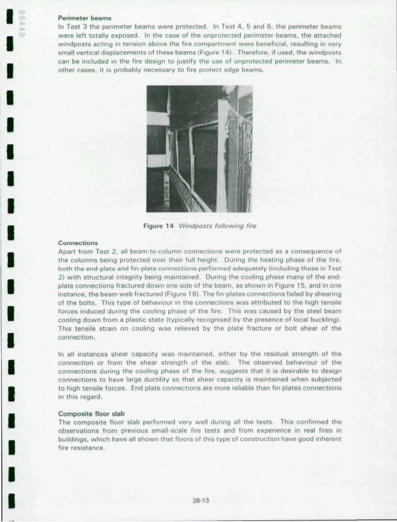
In Test 3 the perimeter beams were protected . In Test 4 , 5 and 6 , the perimeter beams were left totally exposed. In the case of the unprotected perimeter beams, the attached wind posts acting in tension above the fire compartment were benefiCial , resulting In very small vertical displacements of these beams IFigure 14). Therefore, If used , the wlndposts can be Included In the fire design to Jusllfy the use of unprotected perimeter beams. In other cases, It IS probably necessary to fire protect edge beams.
Figure 14 Windposrs following fire
Connections Apart from Test 2, all beam-to-column connections were protected as a consequence of the columns being protected over their full height. DUring the heating phase of the fire, both the end-plate and fin-plate connections performed adequately (including those In Test 2) With structural Integrity being maintained. DUring the cooling phase many of the end plate connections fractured down one Side of the beam , as shown In Figure 15, and In one Instance, the beam web fractured IF,gure 16). The fin-plates connectIOns failed by shearing of the bolts. ThiS type of behaVIOur In the connections was attnbuted to the high tenSile forces induced during the cooling phase of the fire . ThiS was caused by the steel beam cooling down from a plastiC state ItYPlcally recognised by the presence of local buckling) . ThiS tenSile strain on cooling was relieved by the plate fracture or bolt shear of the connection.
In all instances shear capacity was maintained, either by the reSidual strength of the connection or from the shear strength of the slab. The observed behaViour of the connections during the cooling phase of the fire, suggests that It IS deSirable to deSign connections to have large ductility so that shear capacity IS maintained when subjected to high tensile forces. End plate connections are more reliable than fin plates connectIOns in thiS regard.
Composite floor slab The composite floor slab performed very well dUring all the tests. ThiS confirmed the observations from prevIous small ·scale fire tests and from experience In real fires In bUildings, which have all shown that floors of thiS type of construction have good Inherent fire resistance .
28·13

• • •
TyPic.! spill In connectIon oocunno on oooimg
J.j:,.J.,;;t..;:-- Shear cap8Clty malntamed by unsplil SIde of plate
TenSIle fome Induced
on "'0''''''
Figure 15 Fracture of end-plate during the cooling phase of the fire
Fractured fillet weld
End plate tom from beam
Figure 16 Connection detail showing fractures
The bridgingl membrane characteristics of the composite slab had a benefiCial effect on the structural performance of the unprotected beams dUring the tests, when the beams had lost a large proportion of their bending resistance. In the first instance the slab bridges across the weakening heated steel members by utili sing its full moment capacity . As the displacements increase further, the slab then acts as a tensile membrane through the mesh reinforcement. Both types of behaViour are shown diagrammatically in Figure 17 . In the case of tensile membrane act ion , If the supports have no horizontal restraint li.e. t he slab is at an edge of a building) then a compressive membrane ring will eventually form around the area of slab in the cooler part of the compartment , as shown in Figure 18.
To include the beneficial effects of the load carrying capacity of the fl oor slab in structural fire design, its membrane action needs to be fully understood and the span lor sIZe of fire compartment) limits defined . ThiS task is being addressed at present by a number of research organisations.
This action only occurs when a local area of the slab is heated and there is sufficient restraining effect around the perimeter of the heated area . It is not clear how large the heated area can be in order that thiS action is effective in supporting the beams to we ll beyond thei r critical temperature . The slab above protected beams is effective in resisting compression .
28-14
I I I I I I I I I I I I I I I I I I I

I ~
I I I I I I I I I I I I I I I I I I
Figure 17
Heated beam
a) Stldglng action by bending resistance of reinforced concrete slab
Heated beam
b) Bridging action by tensile membrane action of reinforcement
Bridging across a heated beam by the slab acting In bending and membrane actton
Although extenSive cracking was observed In the concrete above the flte compartment, ItS integrity as a compartment floor was generally maintained dutlng the healing phase of the flte. In one test large cracks occurred around an Internal column, creating gaps In the floor slab. Investigation of this area showed that the mesh reinforcement was not lapped correctly , and was Just 'butted' together. It IS clearly important that, to ensure Integtlty of the compartment, and for the capability of utilising tensile membrane action , care should be taken to ensure that the reinforcement is correctly lapped in accordance With normal specificatIOns. Special, high ductility, 'flte englneellng' mesh would certainly be more effective than standard mesh and conSideration IS being given to developing such a mesh.
Compression Zone
Figure 18 Tensile membrane action of slab without horizontal restraint to edges
Compartment walls In Tests 4 and 5, Internal compartment walls were constructed uSing steel stud partitions With flte resistant board . In Test 4, the wall was placed under unprotected beams. Due to the shielding effect of the wall , the vertical deflection of these beams was very small and the integrity of the compartment wall was maintained . In Test 5 , the compartment wall was placed 'off-gild ' and the deflection of the slab caused Integllty failure of the compartment wall.
28-15

Therefore It is advisable, If possible, to place compartment walls under beams WhiCh, as shown In Test 4, leads to nominal vertical deflection of these beams. However, to comply with the insulation Criterion for separating elements, specified in fire testing standards, these beams would normally be protected, incorporating an additional level of safety in maintaining the integrity of the compartment wall.
Comparison with Structural Fire Design Codes Design codes have been based on the results of standard fire resistance tests. As these tests are commonly conducted on single elements the behaviour of these elements are usually different when they are included in the frame. Due to the inherent continUity in the frame providing the capability of transfemng load away from the fire affected areas by a number of mechanisms the behaviour of the full structure makes the guidance given in the design codes appear very conservative. Utilising continuity in the structure relies on compartmentation of the structure limiting the fire affected area to a size in which these mechanisms such as membrane action can successfully redistribute the loads.
Some of the beam results from the Cardington tests are summarised in Table 3 along with the corresponding failure temperatures as given by the design codes. It is interesting to note that the temperatures are all appreciably higher than those which may have been predicted by 855950-8 or the Eurocodes.
The maximum steel temperature reached during the six fire tests at Cardington was in excess of 11 OooC, which occurred with no signs of structural collapse. Using modern fire codes, which are based on the standard fire tests, failure (or structural collapse) was calculated to occur at a critical temperature of approximately 680°C. This supports the hypothesIs that the current level of safety in structural fire resistant design is extremely high . Future work will concentrate on quantifying the current levels of safety and developing definitive design gUidance, which will incorporate a more economical approach to structural fire design .
Test beam Flange temperature at B55950 Part B limiting end of test (OC ) temperature ( ° C )
Restrained beam 850+ 670
20 test 9 metre span 800 720
20 test 6 metre span 800 670
ECSC Corner test 9 metre span 1000+ 670
BRE Corner test 9 metre span 1000+ 670
ECSC Office test 9 metre span 1100 670
Table 3 Measured beam temperatures and 8S5950 Part 8 limiting temperatures
5 DEVELOPMENT OF DESIGN GUIDANCE Following the fire test programme further research has started to try to understand the observed behaviour at Cardington and develop design gUidance. Two groups have been set up: the first, the "science" group has the task of building finite element models of the structure with the aim of understanding the various modes of behaviour and their relative Importance. The second, the "design" group, has the role of developing design aids and disseminating the lessons from Cardington.
The development of design guidance will be in two phases. The first phase is to look carefully at what happened at Cardington and, based largely on observation, give advice and make limited recommendations (Levell). A summary of the Levell guidance in given in Section 5.1 .
28-16
I I I I I I I I I I I I I I I I I I I

I I I I I I I I I I I I I I I I I
The development of comprehensive design rules (Level 2) will necessarily follow the advanced finite element work being carried out by the "science" group . Some difficult problems have to be solved, Interestingly, for the steel Industry, many of these problems relate to modelling concrete behaviour in fire .
The ultimate aim of the research IS to reduce the amounts of applied fire protection in steel framed buildings whilst achieving agreed levels of safety. The research is not a complete answer In Itself but it should allow us to justify a more logical approach to structural fire safety. Any new design philosophy must include measures to ensure that the overall stability of the building is maintained , that the necessary compartmentation is maintained and that the bUilding is safe for fire fighters .
5.1 level 1 Design Guidance
Note: The following summary of proposed recommendations should be read as an indication of the direction that we are moving in the UK. They represent thoughts at the time of writing IJanuary 1999) and may be subject to major change before eventual publication.
Recommendations are being prepared for buildings requiring 15 , 30 and 60 minutes fire resistance. The draft recommendations for 60 minutes are presented here . In the UK approximately 80% of multi storey buildings are reqUired to have 30 or 60 minutes fire resistance .
The proposed design recommendations have been prepared With a number of conSiderations in mind :
1.
2.
3.
For buildings in which the elements of construction require 60 minutes fire resistance damage should be confined to the fire compartment thus making repair possible.
On the fire floor excessive structural deformation will not cause failure of compartmentation, i.e. the fire IS contained Within Its compartment of Origin and should not spread hOrizontally .
The safety of fire fighters is maintained.
The guidance applies to composite steel framed bUildings of the type tested at Cardington. That is to say:
1. The structure is a braced , non-sway frame.
2 . The floors are composite and constructed using a profiled steel deck acting together with a reinforced concrete slab.
3 . The floor beams are down stand I or H sections and act compositely with the floor slab via welded shear connectors .
4 . The beam end connections are simple.
5. The steelwork is designed in accordance 8r1tlsh or European standards.
5.1.1 Fire Resistance
The follOWing recommendations are for buildings In which the elements of structure are required to have 60 minutes fire resistance . That is to say that. if the indiVidual beams, columns and floor slabs were tested in a standard fire resistance test, they would achieve 60 minutes fire resistance .
28·17
5 .1 .2 Recommendations for structural elements
Detailed recommendations are given for beams, columns, floor slabs and connections. Separate recommendations are given for steelwork used in the construction of protected shafts .
Loading In fire conditions advantage can be taken of reductions in load factors for Imposed loads specified In BS 5950-B . The total Imposed load in the fire condition, Including ceiling, services and partitions, on the floor should not exceed 8 kN/m2
•
Beams The span of any beam should not exceed 9 metres.
Beams framing into columns: Provide 60 minutes fire resistance
Beams not framing into columns: No fire protection required.
Edge beams: Provide 60 minutes fire resistance or wind posts at not more than 3 m centres
Load ratio The load ratio, calculated in accordance with BS5950-8 should not exceed 0.6
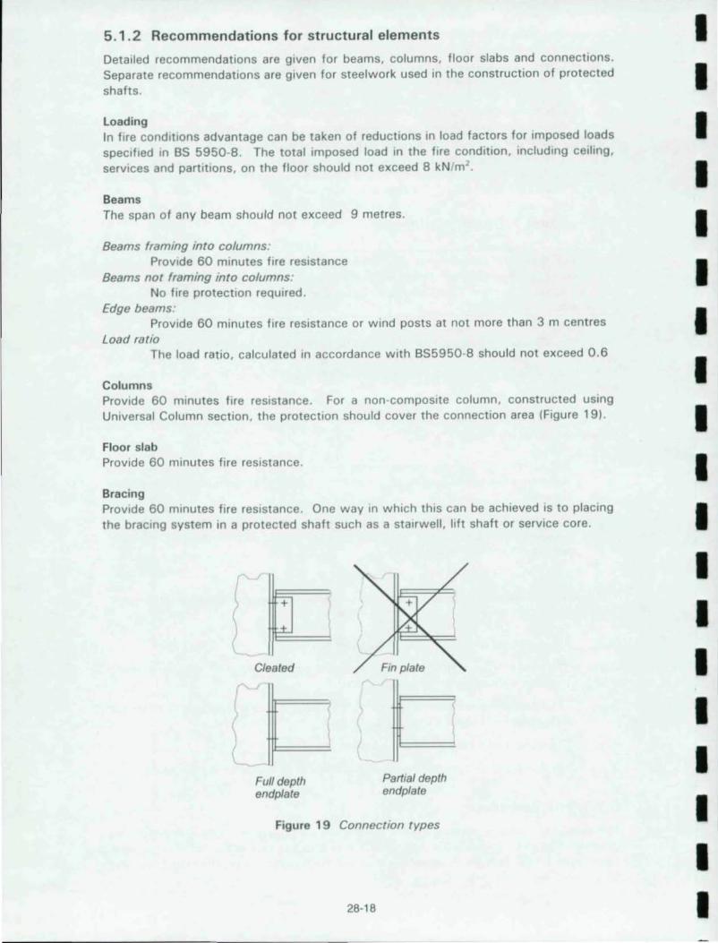
Columns Provide 60 minutes fire resistance . For a non-composite column, constructed uSing Universal Column section, the protection should cover the connection area (Figure 19).
Floor slab Provide 60 minutes fire resistance.
Bracing Provide 60 minutes fire resistance. One way in which this can be achieved IS to placing the bracing system in a protected shaft such as a stairwell, hft shaft or service core.
+
Cleated
Full depth endplate
i
Partial depth endplate
Figure 19 Connection types
26-16
I I I I I I I I I I I I I I I I I I I
I I I I I I I I I I I I I I I I I I
Connections Beam to column and beam to beam:
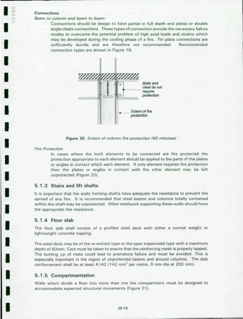
Connections should be design to have partial or full depth end plates or double angle cleats connections. These types of connection provide the necessary failure modes to overcome the potential problem of high axial loads and strains which may be developed during the cooling phase of a fire . Fin plate connections are sufficIently ductile and are therefore not recommended . Recommended connection types are shown in Figure 19.
Boffsaoo cleat do not require protection
ExtfHlt of tim protection
Figure 20 Extent of column fire protection (60 minutesl
Fire Protection In cases where the both elements to be connected are fire protected the protection appropriate to each element should be applied to the parts of the plates or angles in contact which each element . If only element requires fire protection then the plates or angles in contact with the other element may be left unprotected (Figure 20) .
5.1.3 Stairs and lift shafts
It is important that the walls forming shafts have adequate fire resistance to prevent the spread of any fire. It is recommended that steel beams and columns totally contained within the shaft may be unprotected . Other steelwork supporting these walls should have the appropriate fire resistance .
5.1.4 Floor slab
The floor slab shall consist of a profiled steel deck with either a normal weight or lightweight concrete topping.
The steel deck may be of the re-entrant type or the open trapezoidal type with a maximum depth of 60mm. Care must be taken to ensure that the reinforcing mesh is properly lapped. The butting up of mats could lead to premature failure and must be avoided. This is especIally Important in the region of unprotected beams and around columns. The slab reinforcement shall be at least A142 (142 mm' per metre, 6 mm dia at 200 mm).
5.1.5 Compartmentation
Walls which divide a floor into more than one fire compartment must be designed to accommodate expected structural movements (Figure 211 .
28-19

In some cases the deflection allowance may be in the form of a sliding joint but In other cases the potential deflection may be too large and some form of deformable curtain may be required.
(b)
(c) -Deformable blanket
(a) Compartment wall
Figure 21 Positions of compartment walls Figure 22 Large deflection of floor slab
a) Walls below beams
The beams above walls are part of the wall and must be constructed as separating elements, i.e. they must have adequate insulation and integrity.
A bare steel beam will almost certainly fail the insulation requirements so some form of insulation must be applied. It IS recommended that to meet this requirement the beam is fire protected to the general standard being used (60 minutes). In this respect intumescent coatings are not appropriate as they do not react until the steel temperature is above that specified for insulation.
A steel beam without penetrations will have integrity . However, any service penetrations must be properly fire stopped and all voids above composite beams should also be fire stopped.
The tests at Cardington demonstrated that the vertical deflection of beams above and parallel to walls was not a problem so no special recommendations are made regarding deflection heads for walls.
b) Beam crossing wall
In this case the vertical deflectIOn of a beam crossing the wall or the deflection of the floor slab could be large and the construction of the wall must include a suitable deflection allowance (Figure 22).
For a wall below the middle half of a beam the deflection allowance should be equal to span/20. This may be reduced linearly to zero for the end quarters of the beam.
c) Floor slab above wall
In this case the vertical deflection of the floor slab could be large and the construction of the wall must include a suitable deflectIOn allowance.
The deflection allowance should be based on the middle half of any span having a deflection of span /20 with a linear reductIOn to zero at the ends. The deflection of supporting beams should be assessed In a similar manner.
28-20
I I I I I I I I I I I I I I I I I I I

I I I I I I I I I I I I I I I I I
6 CONCLUSIONS In this paper the authors have described some of the research Into structural fire engineering which are taking place in UK and Europe. In particular the Cardington fire tests have been described and possible design recommendations presented. Important differences between European and North American building regulations and fire testing procedures have also been highlighted .
The team developing 'post-Cardington ' design guidance are continuing to study the behaViour of multistorey bUildings in fire but following publication of Levell gUidance labout the time of this conference) more detailed design recommendations are probably another three years away .
For the Cardington studies to have any Impact the industry must convince the specifiers and the regulators that satisfactory safety standards are maintained and that economies of some kind can be made . The former POint IS very Important. The key word IS ·satisfactory". It is clear that existing standards for fire protecting structures are not logical. Beams do not always require the same amount of fire resistance or fire protection as columns, provided that continuity through a composite floor can be guaranteed .
Any new design philosophy must Include measures to ensure that the overall stability of the building is maintained, that the necessary compartmentatlon IS maintained and that the building IS safe for fire fighters . We face an Interesting and challenging future .
28·21

7
1 .
2.
3.
4 .
5.
6.
7.
REFERENCES
Title unknown at time of writing A description of all the fire tests will be published during the early part of 1 999 by British Steel (Technical). The data will also be made available. Contact: Dr B R Kirby British Steel
Swinden Technology Centre Moorgate Rotherham, UK Tel + 44 (0) 1709 820166 Fax + 44 (0) 1909 825337
BRITISH STANDARDS INSTITUTION BS 5950: The Structural Use of Steelwork in Buildings Part 8: Code of Practice for Fire Resistant Design, BSI , 1990
STEEL CONSTRUCTION INDUSTRY FORUM Structural fire engineering, Investigation of Broadgate Phase 8 fire Steel Construction Institute, 1991
BRITISH STANDARDS INSTITUTION BS ENV 1993: Eurocode 3: Design of steel structures Part 1.2 Structural fire design (including UK NAD) BSI, expected early 1999
BRITISH STANDARDS INSTITUTION BS ENV 1994: Eurocode 4: Desi9n of composite steel and concrete structures Part 1.2 Structural fire design (including UK NAD) BSI, expected early 1999
BAILEY C G, NEWMAN G M, SIMMS W I The design of steel framed bu ildings w ithout applied fire protection The Steel Construction Institute, P186, 1999
BRITISH STANDARDS INSTITUTION DD240, Fire safety engineering in buildings BSI, 1997
28-22
I I I I I I I I I I I I I I I I I I I