i t ay p o f b m firelock v36, k8.0 p r models … product data revised … · factory hydrostatic...
TRANSCRIPT

Technical Specifications:
Models: V3612 and V3611
Style: Horizontal Sidewall and Recessed HorizontalSidewall
Nominal Orifice Size: 17/32"/14 mm
Orifice Insert: Stainless steel per UNS S30300
K-Factor: 8.0 Imp./11.5 S.I.1
Nominal Thread Size: 1" NPT/33.7 mm
Max. Working Pressure: 175 psi/1200 kPa
Factory Hydrostatic Test: 100% @ 500 psi/3450 kPa
Min. Operating Pressure: 7psi/48 kPa
Temperature Rating: See chart on page 3.1 For K-Factor when pressure is measured in Bar, multiply S.I. units by 10.0.
Dry Type PendantsStandard and Quick Response
Approvals/Listings:
See Victaulic Publication 10.01 for more details.
Product Description:
The V36 Dry Sprinkler is used in special applicationssuch as freezing environments and conditions wheresediment or foreign materials might accumulate inordinary horizontal pipe nipples.
The Model V36 Dry Type Horizontal Sidewall Sprinklerutilizes a frangible glass bulb. At the bulb’s ratedtemperature, the sprinkler opens releasing the bulb seatassembly, causing the inner tube assembly to move, allowingthe spring assembly to pivot alongside the inner tube. At thistime, water flows through the sprinkler and is distributed bythe deflector, in an approved discharge pattern.
Coverage:
For coverage area and sprinkler placement, refer toNFPA 13 or applicable standards.
FlushHorizontal Sidewall
Dry Sleeve & SkirtHorizontal Sidewall
Dry RecessedHorizontal Sidewall
ExtendedHorizontal Sidewall
PlainHorizontal Sidewall
Exaggerated for clarity
Exaggerated for clarity
FireLock® V36, K8.0Models V3611, V3612
40.65
1
victaulic.com | Sprinklers | FireLock® | K8.0, V36 | Publication 40.6540.65 3128 Rev. K Updated 6/2014 © 2014 Victaulic Company. All rights reserved.
Job/Owner
System No.
Location
Contractor
Submitted By
Date
Engineer
Spec Section
Paragraph
Approved
Date
CITY O
F MED
FORD
APPRO
VED
Sam Barnum
03/29/18

Material Specifications:
Deflector: Brass per UNS C22000 or Stainless Steel per UNS S30400
Bulb: Glass with glycerin solution
Bulb Nominal Diameter:
Standard: 5.0 mm
Quick Response: 3.0 mm
Split Spacer: Stainless steel per UNS S30300
Load Screw: Brass per UNS C36000
Pip Cap: Stainless steel per UNS S30300
Spring Seal Assembly: Teflon2 coated Beryllium nickelalloy and stainless steel per UNS S30300
Frame: Die cast brass
Outer Tube: Galvanized steel pipe
Inner Tube: Stainless steel per UNS S30400
Escutcheon/Plate: 1010 - 1018 mild steel and stainlesssteel
Torsion Spring: SST Wire
Accessories
Installation Wrench:
Model V36 Open End and Recessed Wrenches fit allV36 Series frames.
Sprinkler Finishes:
Plain brass
Chrome plated
White painted3 4
Flat black painted3 4
Custom painted3 4
Proprietary Nickel Teflon2 Coated4
VC-2505
155, 200, 286 SR Only:
Wax4
For cabinets and other accessories refer to separatesheet.2 Teflon is a registered trademark of Dupont Co.
3 Not available on the Intermediate Level Style Pendent.
4 UL Listed for corrosion resistance.
5 UL Listed and FM Approved for corrosion resistance.
NOTE: Weather resistant escutcheon available upon request.
2
victaulic.com | Sprinklers | FireLock® | K8.0, V36 | Publication 40.65
40.65 3128 Rev. K Updated 6/2014 © 2014 Victaulic Company. All rights reserved.
victaulic.com
CITY O
F MED
FORD
APPRO
VED
Sam Barnum
03/29/18

Approvals/Listings:
APPROVALS/LISTINGSModel
V3612 V3612 V3611 V3611
Orifice Size (inches) 17/32 17/32 17/32 17/32
Orifice Size (mm) 14 14 14 14
Nominal K Factor Imperial 8.0 8.0 8.0 8.0
Nominal K Factor S.I.6 11.5 11.5 11.5 11.5
Response Quick Quick Standard Standard
Deflector Type Horizontal SidewallRecessed Horizontal
SidewallHorizontal Sidewall
Recessed HorizontalSidewall
Approved Temperature Ratings F°/C°
cULus 7
135°F/57°C155°F/68°C 200°F/93°C286°F/141°C
135°F/57°C155°F/68°C 200°F/93°C286°F/141°C
135°F/57°C155°F/68°C 200°F/93°C286°F/141°C
135°F/57°C155°F/68°C 200°F/93°C286°F/141°C
6 For K-Factor when pressure is measured in Bar, multiply S.I. units by 10.
7 Approved for V3605 and V3606 dry sprinklers up to 48" length.
Note: Listings and approval as of printing. Light hazard or ordinary hazard.
Dimensions:
NOTE : The “A” dimension of a dry sprinkler, which extends into a freezer from a wet piping system, must take into account the wall or ceiling thickness of the
freezer. See IMPORTANT INSTALLATION INFORMATION later in this document.
same outlet size
prinkler thread size
1" NPT
1½" Min. Dia.
Hole in Wall 3" Dia.
"A"
(Min. 1¼")
2½"
¼"
Flush
Tee with same outlet sizeas sprinkler thread size
See page 4, No. 2
1" NPT
"A"(Min. 1½")
2"
Plain Barrel
Tee with same outlet size
as sprinkler thread size
1" NPT
1¾" Min. Dia.
Hole in Wall
3"
Dia.
Two Piece
Escutcheon
"A"
(Min. 1¼")
3" Min.4½" Max.
Sleeve & Skirt
Tee with same outlet size
as sprinkler thread size
1" NPT
"A"
(Min. 1¼")
1½" Min. Dia.
Hole in Wall
Two Piece
Escutcheon
4" Min.
5¼" Max.
3½"
Dia.
Extended
Tee with same outlet size
as sprinkler thread size
1" NPT
2" Min. Dia.
Hole in Wall
2"
Dia.
"A"(Min. 1¾")
Wall Cup
Collar
1" Min.
2" Max.
Recessed
Deflector To Ceiling Distance 4 – 12"/102 – 305 mmFor All Configurations Shown Above.
Tee with same outlet size as sprinkler thread size.
See “Important InstallationInformation”, later in this
document
Tee with same outlet size as sprinkler thread size.
See “Important InstallationInformation”, later in this
document
Tee with same outlet size as sprinkler thread size.
See “Important InstallationInformation”, later in this
document
Tee with same outlet size as sprinkler thread size.
See “Important InstallationInformation”, later in this
document
Tee with same outlet size as sprinkler thread size.
See “Important InstallationInformation”, later in this
document
3
victaulic.com | Sprinklers | FireLock® | K8.0, V36 | Publication 40.65
40.65 3128 Rev. K Updated 6/2014 © 2014 Victaulic Company. All rights reserved.
victaulic.com
CITY O
F MED
FORD
APPRO
VED
Sam Barnum
03/29/18

Important Installation Information:
For detailed installation instructions, see publication I-40.
No. 1 Victaulic Model V36 Series Dry sprinklers should be installed in accordance with NFPA 13. These sprinklers are to be installed using a pipe wrench applied to the outer tube. When this is not possible, the proper sprinkler wrench may be used with extreme care for lengths up to approximately 18". Excessive force may distort the frame thus destroying the unit.
No. 2 Dry sprinklers MUST be installed only into the outlet of a cast or malleable iron tee.
No. 3 DO NOT install dry sprinklers into any couplings or threaded elbows. In addition, DO NOT install dry sprinklers into any fitting that interferes with thread penetration. NOTE : The end seal of the dry sprinkler MUST NOT bottom out in the fitting.
Diameter of hole is dependent upon thetype of escutcheon selected. Space mustbe sealed to prevent condensation fromforming, per NFPA requirements.
End Seal
Insulation
Wall or Ceiling of Freezer
Exaggerated for Clarity
�A�See Note
�C� Exposed Minimum BarrelLength (Refer to Table)
�D�
HEATED SPACE
COLD SPACE
TYPICAL SLEEVE AND SKIRT CONFIGURATION FOR EXAMPLE ONLY
NOTE :
The “A” dimension of a dry sprinkler, which extends into a freezer from a
wet piping system, must take into account the wall or ceiling thickness of the
freezer. The minimum length of the dry sprinkler should not be less than the
lengths specified in the following table, plus the thickness of the freezer’s wall
or ceiling (“A” = “C” + “D”).
Refer to the drawing for a representation of the “A” dimension. DO NOT
attempt to modify dry sprinklers, since they are manufactured to this specific
“A” dimension.
The following table is used when the ambient temperature is maintained
between 40° F/4° C and 60°F/16°C around the wet piping system.
Ambient TemperatureExposed to Discharge
End of Sprinkler °F/°C
Exposed Minimum Barrel Lengthinches/mm
40°F/4°C 50°F/10°C 60°F/16°C
40 0 0 04 0 0 0
30 0 0 0-1 0 0 0
20 4 0 0-7 102 0 0
10 8 1 0-12 203 25 0
0 12 3 0-18 305 76 0
-10 14 4 1
-23 356 102 25
-20 14 6 3
-29 356 152 76
-30 16 8 4-34 406 203 102
-40 18 8 4-40 457 203 102
-50 20 10 6-46 508 254 152
-60 20 10 6-51 508 254 152
Note: Exposed minimum barrel lengths are inclusive up to 30-mph/48-kph
wind velocities
4
victaulic.com | Sprinklers | FireLock® | K8.0, V36 | Publication 40.65
40.65 3128 Rev. K Updated 6/2014 © 2014 Victaulic Company. All rights reserved.
victaulic.com
CITY O
F MED
FORD
APPRO
VED
Sam Barnum
03/29/18

NOTES:
A. Data shown is approximate and can vary due to differences in installation.
B. These graphs illustrate approximate trajectories, floor-wetting, and wall-wetting patterns for these specific Victaulic FireLock automatic sprinklers. They are
provided as information for guidance in avoiding obstructions to sprinklers and should not be used as minimum sprinkler spacing rules for installation. Refer to the appropriate NFPA National Fire Code and the Authority Having Jurisdiction for specific information regarding obstructions, spacing limitations and area of coverage requirements. Failure to follow these guidelines could adversely affect the performance of the sprinkler and will void all Listings, Approvals and
Warranties.
C. All patterns are symmetrical to the centerline of the waterway.
Distribution Patterns:
Models V3612, V3611
Horizontal Sidewall and Recessed Horizontal Sidewall
Distribution Patterns – Trajectory
7 psi48 kPa
15 psi103 kPa
30 psi207 kPa
0
2'0.6 m
4'1.2 m
6'1.8 m
8'2.4 m
10'3.0 m
10' 3.0 m
12' 3.7 m
14'4.3 m
2' 0.6 m
4'1.2 m
6'1.8 m
8'2.4 m
22' 6.7 m
24' 7.3 m
26'7.9 m
16'4.9 m
18'5.5 m
20'6.1 m
7 psi48 kPa
15 psi103 kPa
30 psi207 kPa
0
8'2.4 m
6'1.8 m
4'1.2 m
2'0.6 m
16'4.9 m
14'4.3 m
12'3.7 m
10'3.0 m
10' 3.0 m
12' 3.7 m
14'4.3 m
2' 0.6 m
4'1.2 m
6'1.8 m
8'2.4 m
22' 6.7 m
24' 7.3 m
26' 7.9 m
28'8.5 m
16'4.9 m
18'5.5 m
20'6.1 m
Models V3612, V3611
Horizontal Sidewall and Recessed Horizontal Sidewall
Distribution Patterns – Plan View
5
victaulic.com | Sprinklers | FireLock® | K8.0, V36 | Publication 40.65
40.65 3128 Rev. K Updated 6/2014 © 2014 Victaulic Company. All rights reserved.
victaulic.com
CITY O
F MED
FORD
APPRO
VED
Sam Barnum
03/29/18

InstallationReference should always be made to the I-100 Victaulic Field Installation Handbook forthe product you are installing. Handbooks are included with each shipment of Victaulicproducts for complete installation and assembly data, and are available in PDF format on our website at www.victaulic.com.
WarrantyRefer to the Warranty section of the current Price List or contact Victaulic for details.
Note
This product shall be manufactured by Victaulic or to Victaulic specifications. All productsto be installed in accordance with current Victaulic installation/assembly instructions.Victaulic reserves the right to change product specifications and standard equipmentwithout notice and without incurring obligations.
Trademarks
Victaulic and Firelock® are registered trademarks of Victaulic Company.
Ratings:
All glass bulbs are rated for temperatures from -67°F/-55°Cto those shown in table below:
Available Wrenches:
Model V36 Open End and Recessed Wrenches fit allV36 Series frames.
WARNING
• Always read and understand installation, care, and maintenance instructions, supplied with each box of sprin-klers, before proceeding with installation of any sprinklers.
• Always wear safety glasses and foot protection.
• Depressurize and drain the piping system before attempting to install, remove, or adjust any Victaulic pipingproducts.
• Installation rules, especially those governing obstruction, must be strictly followed.
• Painting, plating, or any re-coating of sprinklers (other than that supplied by Victaulic) is not allowed.
Failure to follow these instructions could result in serious personal injury and/or property damage.
The owner is responsible for maintaining the fire protection system and devices in proper operating condition. Forminimum maintenance and inspection requirements, refer to the current National Fire Protection Association pam-phlet that describes care and maintenance of sprinkler systems. In addition, the authority having jurisdiction mayhave additional maintenance, testing, and inspection requirements that must be followed.
If you need additional copies of this publication, or if you have any questions about the safe installation of thisproduct, contact Victaulic World Headquarters: P.O. Box 31, Easton, Pennsylvania 18044-0031 USA, Telephone:001-610-559-3300.
SprinklerTemperatureClassification
VictaulicPart
Identification
Temperature – ºF/ºC
Glass Bulb Color
Nominal Temperature
Rating
MaximumAmbient
TemperatureAllowed
Ordinary A 135ºF/57ºC 100ºF/38ºC Orange
Ordinary C 155ºF/68ºC 100ºF/38ºC Red
Intermediate E 175ºF/79ºC 150ºF/65ºC Yellow
Intermediate F 200ºF/93ºC 150ºF/65ºC Green
High J 286ºF/141ºC 225ºF /107ºC Blue
Extra High K 360ºF/182ºC 300ºF/149ºC Purple
– M Open – No Bulb
40.65 3128 Rev. K Updated 6/2014 © 2014 Victaulic Company. All rights reserved.
victaulic.com 6
victaulic.com | Sprinklers | FireLock® | K8.0, V36 | Publication 40.65
CITY O
F MED
FORD
APPRO
VED
Sam Barnum
03/29/18

Series ELO-231 – 11.2 K-factorUpright and Pendent SprinklersStandard Response, Standard Coverage
Page 1 of 4 JANUARY 2017 TFP340
IMPORTANT
Always refer to Technical DataSheet TFP700 for the “INSTALLER WARNING” that provides cautionswith respect to handling and instal-lation of sprinkler systems and com-ponents. Improper handling andinstallation can permanently damagea sprinkler system or its compo-nents and cause the sprinkler to fail to operate in a fire situation or cause it to operate prematurely.
Worldwide
Contactswww.tyco-fire.com
GeneralDescriptionTYCO Series ELO-231 11.2K Stan-dard Response, Standard CoverageUpright and Pendent Sprinklers (Ref.Figure 1) are automatic sprinklers ofthe fusible solder type. They are stan-dard response, spray sprinklers thatproduce a hemispherical water distri-bution pattern below the deflector.
The 11.2 K-factor, ELO-231 Sprinklerswere subjected to full scale, high-piledstorage, fire tests to qualify their usein lieu of 5.6 or 8.0 K-factor standardspray sprinklers for the protection ofhigh-piled storage.
Higher flow rates can be achieved atmuch lower pressures with the 11.2K-factor, ELO-231 Sprinklers, makingtheir use highly advantageous in highdensity applications, such as the pro-tection of high-piled storage.
Wax or lead coatings can be usedto extend the life of the copper alloycomponents used in Series ELO-231sprinklers beyond that which wouldotherwise be obtained when exposedto corrosive atmospheres. Althoughwax and lead coated sprinklers havepassed the standard corrosion tests ofthe applicable approval agencies, thetesting is not representative of all pos-sible corrosive atmospheres. Conse-quently, it is recommended that the enduser be consulted with respect to thesuitability of these corrosion resistantcoatings for any given corrosive envi-ronment. The effects of ambient tem-perature, concentration of chemicals,
and gas/chemical velocity, should beconsidered, as a minimum, along withthe corrosive nature of the chemical towhich the sprinklers will be exposed.
An upright intermediate level versionof the Series ELO-231 Sprinklers forin-rack applications can be obtainedby utilizing the Series ELO-231 UprightSprinkler with the WSG-2 Guard &Shield, and a pendent intermediatelevel version of the Series ELO-231Sprinklers can be obtained by utilizingthe Series ELO-231 Pendent Sprinklerwith the WS-2 Shield. If there is a pos-sibility of the pendent intermediate levelversion being exposed to mechanicaldamage, a G-2 Guard can be added.
NOTICE
The 11.2 K-factor, Series ELO-231Upright and Pendent Sprinklersdescribed herein must be installedand maintained in compliance with thisdocument, as well as with the applica-ble standards of the National Fire Pro-tection Association (NFPA), in additionto the standards of any other authori-ties having jurisdiction. Failure to do somay impair the performance of thesedevices.
The owner is responsible for main-taining their fire protection systemand devices in proper operating con-dition. Contact the installing contrac-tor or product manufacturer with anyquestions.
Installation of Series ELO-231 PendentSprinklers in recessed escutcheons willvoid all sprinkler warranties, as well aspossibly void the sprinkler’s Approvalsand/or Listings.
SprinklerIdentificationNumbers (SINs)TY5111 – Upright 11.2K, 3/4” NPTTY5211 – Pendent 11.2K, 3/4” NPTTY5811 – Upright 11.2K, 1/2” NPTTY5111 is a redesignation for CentralSIN C5111.
TY5211 is a redesignation for CentralSIN C5211.
TY5811 is a redesignation for CentralSIN C5811.
Existing Upright SprinklersCITY O
F MED
FORD
APPRO
VED
Sam Barnum
03/29/18

TFP340
Page 2 of 4
TechnicalDataApprovalsUL and C-UL ListedFM ApprovedNYC Approved
(Refer to Table A for complete approvalinformation, including corrosion-resis-tant status. The approvals apply tothe service conditions indicated in theDesign Criteria section.)
Maximum Working Pressure175 psi (12,1 bar)
Discharge CoefficientK=11.2 gpm/psi1/2 (161,4 lpm/bar1/2)
Temperature RatingsRefer to Table A
FinishesRefer to Table A
Physical CharacteristicsFrame . . . . . . . . . . . . . . . . . . . . . . . . . . . .BronzeSeal Disc . . . . . . . . . . . . . . . . . . . . . . . . . CopperCap . . . . . . . . . . . . . . . . . . . . . . . . . . . . . .BronzeStrut Assembly . .Solder, Bronze Stainless SteelCompression Screw . . . . . . . . . . . . . . . . .BronzeDeflector . . . . . . . . . . . . . . . . . . . . . . . . . .BronzeHelper Spring . . . . . . . . . . . . . . . Stainless SteelEjector Spring . . . . . . . . . . . . . . . . . . . . . . NickelStrut Clip . . . . . . . . . . . . . . . . . . . Stainless Steel
DesignCriteriaUL and C-ULListing RequirementsTYCO Series ELO-231 11.2K StandardResponse, Standard Coverage Uprightand Pendent Sprinklers are to beinstalled in accordance with NFPA 13standard sprinkler position and area/density flow calculation requirementsfor light, ordinary, or extra hazard occu-
pancies, as well as high piled storageoccupancies (solid piled, palletized,rack storage, bin box, and shelf storageincluding but not limited to Class I-IVand Group A plastics) with a minimumresidual (flowing) pressure of 7 psi(0,5 bar) for wet or dry pipe systems.
FM Approval RequirementsThe 11.2 K-factor, Model ELO-231(TY5111, TY5211, and TY5811) Sprin-klers are to be installed in accordancewith the applicable control modedensity/area guidelines provided byFM Global. (FM Approval guidelinesmay differ from UL and C-UL Listingcriteria.)
OperationA fusible alloy is sealed into a bronzeactuating rod (center strut) by a stain-less steel ball. When the alloy melts atits rated temperature, the ball is forcedupward into the center strut, releas-ing the two ejectors and operating thesprinkler.
InstallationTYCO Series ELO-231 11.2K Stan-dard Response, Standard CoverageUpright and Pendent Sprinklers mustbe installed in accordance with thissection.
A leak-tight 3/4 inch NPT sprinkler jointshould be obtained by applying a min-imum-to-maximum torque of 10 to 20lbs.-ft. (13,4 to 26,8 Nm). A leak-tight1/2 inch NPT sprinkler joint should beobtained by applying a minimum-to-maximum torque of 7 to 14 lbs.-ft. (9,5to 19,0 Nm). Higher levels of torquecan distort the sprinkler inlet with con-sequent leakage or impairment of thesprinkler.
Do not attempt to make up for insuf-ficient adjustment in the escutcheonplate by under- or over-tightening thesprinkler. Re-adjust the position of thesprinkler fitting to suit.
The Series ELO-231 Upright andPendent Sprinklers must be installedin accordance with the followinginstructions:
Step 1. Pendent sprinklers are to beinstalled in the pendent position, andupright sprinklers are to be installed inthe upright position.
Step 2. With pipe thread sealantapplied to the pipe threads, handtighten the sprinkler into the sprinklerfitting.
Step 3. Tighten the sprinkler into thesprinkler fitting using only the W-Type 3Sprinkler Wrench (Ref. Figure 2), exceptthat an 8 or 10 inch adjustable Crescentwrench is to be used for wax coatedsprinklers. With reference to Figure 1,the W-Type 3 Sprinkler Wrench or theadjustable wrench, as applicable, is tobe applied to the wrench flats.
*
*
PENDENTTY5211
UPRIGHTTY5811
UPRIGHTTY5111
CROSSSECTION
2-13/16"(71,4 mm)
TYP.WRENCH
FLATSTHREADRELIEF
3/4"NPT
3/4"NPT
1/2" (12,7 mm)NOMINAL MAKE-IN
1/2" (12,7 mm)NOMINAL MAKE-IN
7/16" (11,1 mm)NOMINAL MAKE-IN
1/2"NPT
2
6
8
9
7
4
5
3
1
Compression
StrutAssembly
Components:
Seal DiscCap
Frame
Strut ClipSpringEjectorSpringHelperDeectorScrew
- 4
8
9 -
-
5
7 6 -
-
-
1 2 3
- -
-
indicated onrating isTemperature
deector
"FITTING SIDE"
FITTINGTOWARDS SPRINKLER
RECESSWRENCH
(END "A")
FIGURE 1SERIES ELO-231 11.2K UPRIGHT - 3/4” NPT (TY5111), UPRIGHT - 1/2” NPT (TY5811), AND
PENDENT - 3/4” NPT (TY5211) SPRINKLERS
FIGURE 2W-TYPE 3
SPRINKLER WRENCH
CITY O
F MED
FORD
APPRO
VED
Sam Barnum
03/29/18

TFP340
Page 3 of 4
When installing wax-coated sprinklerswith the adjustable wrench, additionalcare needs to be exercised to preventdamage to the wax coating on thesprinkler wrench flats or frame armsand, consequently, exposure of baremetal to the corrosive environment.The jaws of the wrench should beopened sufficiently wide to pass overthe wrench flats without damaging thewax coating. Before wrench-tighteningthe sprinkler, the jaws of the wrench areto be adjusted to just contact the sprin-kler wrench flats. After wrench-tight-ening the sprinkler, loosen the wrenchjaws before removing the wrench.
After installation, the sprinklerwrench flats and frame arms mustbe inspected and the wax coatingre-touched (repaired) whenever thecoating has been damaged and baremetal is exposed. The wax coatingon the wrench flats can be retouchedby gently applying a heated 1/8 inchdiameter steel rod to the areas of waxthat have been damaged, to smooth itback over areas where bare metal isexposed.
Note: Only retouching of the wax coatingapplied to the wrench flats and framearms is permitted, and the retouchingis to be performed only at the time ofthe initial sprinkler installation.
The steel rod should be heated onlyto the point at which it can begin tomelt the wax, and appropriate precau-tions need to be taken, when handlingthe heated rod, in order to prevent theinstaller from being burned.
If attempts to retouch the wax coatingwith complete coverage are unsuc-cessful, additional wax can be orderedin the form of a wax stick (the end ofwhich is color coded). Only the correctcolor-coded wax is to be used, andretouching of wrench flats and framearms is only permitted at the timeof initial sprinkler installation. Withthe steel rod heated as previouslydescribed, touch the rod to the arearequiring additional wax with the rodangled downward, and then touchthe wax stick to the rod approximately1/2 inch away from the area requiringretouching. The wax will melt and rundown onto the sprinkler.
Care andMaintenanceTYCO Series ELO-231 11.2K StandardResponse, Standard Coverage Uprightand Pendent Sprinklers must be main-tained and serviced in accordance withthis section.
Before closing a fire protection systemcontrol valve for maintenance work onthe fire protection system that it con-trols, permission to shut down theaffected fire protection system mustbe obtained from the proper authoritiesand all personnel who may be affectedby this action must be notified.
Sprinklers that are found to be leakingor exhibiting visible signs of corrosionmust be replaced.
Automatic sprinklers must never be painted, plated, coated or otherwisealtered after leaving the factory. Modi-fied or over-heated sprinklers must bereplaced.
Care must be exercised to avoiddam-age to the sprinklers before,during, and after installation. Sprin-klers damaged by dropping, striking,wrench twist/slippage, or the like, mustbe replaced.
Frequent visual inspections are rec-ommended to be initially performedfor corrosion resistant sprinklers, afterthe installation has been completed, toverify the long term potential integrityof the sprinkler coatings. Thereafter,annual inspections per NFPA 25 shouldsuffice; however, instead of inspectingfrom the floor level, a random samplingof close-up visual inspections shouldbe made, so as to better determine theexact sprinkler condition and the longterm integrity of the corrosion resistantcoating, as it may be affected by thecorrosive conditions present.
The owner is responsible for theinspection, testing, and maintenance oftheir fire protection system and devicesin compliance with this document, aswell as with the applicable standardsof the National Fire Protection Asso-ciation (e.g., NFPA 25), in addition tothe standards of any other authoritieshaving jurisdiction. Contact the install-ing contractor or product manufacturerwith any questions.
It is recommended that automaticsprinkler systems be inspected, tested,and maintained by a qualified Inspec-tion Service in accordance with localrequirements and/or national codes.
SPRINKLERTYPE
TEMPERATURERATING
FRAMECOLOR
SPRINKLER FINISH
NATURALBRASS
CHROMEPLATED
LEADCOATED
WAXCOATED
WAX-OVER-LEADCOATED
UPRIGHT(TY5111 & TY5811)
165°F (74°C) Unpainted
1, 2, 3, 41, 2, 3, 4
212°F (100°C) White
286°F (141°C) Blue 1, 2, 3, 4 1*, 2*, 3*, 4*
PENDENT(TY5211)
165°F (74°C) Unpainted
1, 2, 3, 41, 2, 4
212°F (100°C) White
286°F (141°C) Blue 1, 2, 4 1*, 2*, 4*
Notes:1. UL Listed2. C-Ul Listed
3. FM Approved4. Approved by the City of New York (NYC) under MEA 291-04-E* Listed/Approved for a maximum ceiling temperature of 150°F (66°C)
TABLE A11.2K SERIES ELO-231 UPRIGHT & PENDENT SPRINKLERS, STANDARD RESPONSE
LABORATORY LISTINGS AND APPROVALS
CITY O
F MED
FORD
APPRO
VED
Sam Barnum
03/29/18

GLOBAL HEADQUARTERS | 1400 Pennbrook Parkway, Lansdale, PA 19446 | Telephone +1-215-362-0700
TFP340
Page 4 of 4
Copyright © 2017 Tyco Fire Products, LP. All rights reserved.
LimitedWarrantyFor warranty terms and conditions, visitwww.tyco-fire.com.
OrderingProcedureContact your local distributor for avail-ability. When placing an order, indicatethe full product name and part number(P/N).
SprinklerSpecify: ELO-231 11.2K StandardResponse (specify Pendent or Upright)Sprinkler, SIN (specify), temperaturerating (specify), with (specify) finish,P/N (specify from Table B)
Sprinkler WrenchSpecify: W-Type 3 Sprinkler Wrench,P/N 56-895-1-001
Wax Sticks(for retouching wrench-damaged waxcoating)
Specify: (specify Color) color-codedWax Stick for retouching (specifytemperature rating) temperature-rated Series ELO-231 Sprinklers,P/N (specify):
Red for 165°F. . . . . . . . . . . . . . . . . 56-065-1-155Blue for 212°F and 286°F . . . . . . . 56-065-1-286
Note: Each wax stick is suitable forretouching up to twenty-five sprinklers.The wax used for 286°F sprinklers isthe same as for 212°F sprinklers, and,therefore, the 286°F sprinkler is limitedto the same maximum ceiling tempera-ture as the 212°F sprinkler (i.e., 150°F).
P/N 50 – XXX – X – XXX
SPRINKLERFINISH
1 NATURALBRASS
6 WAXCOATED
7 LEADCOATED
8 WAX-OVER-LEADCOATED
9 CHROMEPLATED
SIN
110 11.2K UPRIGHT (3/4” NPT) TY5111
112 11.2K PENDENT (3/4” NPT) TY5211
210 11.2K UPRIGHT (1/2” NPT) TY2811
TEMPERATURERATING
165 165°F (74°C)
212 212°F (100°C)
286 286°F (141°C)
TABLE BSERIES ELO231 11.2K UPRIGHT AND PENDENT SPRINKLERS, STANDARD RESPONSE
PART NUMBER SELECTION
CITY O
F MED
FORD
APPRO
VED
Sam Barnum
03/29/18

Reliable Automatic Sprinkler Co., Inc., 103 Fairview Park Drive, Elmsford, New York 10523
Bu
lletin
12
9R
ev. L
Bulletin 129 Rev. L
Model G XLO K11.2 (160 metric)Standard SprayStandard Response
Storage and Non-storage Sprinkler
Extra Large Orifi ce Sprinkler(SIN R2921) Upright(SIN R2916) Pendent
Features1. Upright cULus Listed as a Control Mode Density Area
(CMDA) sprinkler for storage & non-storage protection.2. Upright and Pendent FM Approved as Standard-re-
sponse, storage, non-storage and CMDA sprinklers.3. Standard ¾-inch NPT or ISO 7-R¾ threads; optional
½-inch NPT or ISO 7-R½ threads for upright retrofit ap-plications only.
4. The ¾” G XLO upright is cULus listed to be used withthe D-6 guard/shield and is FM approved to be usedwith the D-7 guard/shield. The G XLO pendent is FM ap-proved to be used with the D-8 guard or the D-9 guard/
shield. See Bulletin 208.
Listings & Approvals:The following organizations provide Listings or Approvalsfor Model G XLO sprinklers. See the Technical Data tablefor listing and approvals applicable to each sprinkler.1. Underwriters Laboratories, Inc. and Underwriters
Laboratories of Canada (cULus) - Upright only.2. Approved by Factory Mutual (FM) as a storage,
non-storage, and CMDA sprinkler - Upright andPendent.
UL Guide NumberVNIV
UL Listing CategorySprinklers, Automatic and Open; Sprinklers for StorageProtection (Control Mode Density Area)
Technical Data
SprinklerType
Nominal K FactorSprinkler
HeightApprovals
SprinklerIdentifi cation Number (SIN)
US Metric
Upright 0.64Orifice with
¾” NPT (R¾)11.2 160
2.71”(68.8mm)
cULus, FM R2921
UprightRetrofit 0.64Orifice with
½” NPT (R½)
11.2 1602.82”
(71.6mm)cULus, FM R2921
Pendent 0.64Orifice with
¾” NPT (R¾)11.2 160
2.71”(68.8mm)
FM R2916
Note: This product has been tested and listed for storage applicationsto qualify its use in lieu of 5.6K or 8.0K Factor sprinklers for theprotection of high-piled storage.
Product DescriptionThe Reliable Model G XLO sprinkler is a center strut, solder
in compression, extra large orifice sprinkler that has been de-signed for storage and non-storage applications. The Model GXLO sprinkler is available in either an upright or pendent con-figuration. The Model G XLO sprinkler is available with either3/4-inch NPT or ISO 7-R3/4 threads. The Model G XLO Uprightis optionally available with either 1/2-inch NPT or ISO 7-R1/2threads for retrofit applications only.
Design CriteriaThe Model G XLO sprinkler is intended for use as a standard
response standard spray sprinkler in hydraulically designedsprinkler systems with a minimum pressure of 7 psi (0.5 bar) inaccordance with the area/density curves of NFPA 13 or in ac-cordance with FM Property Loss Prevention Data Sheets.
The Model G XLO sprinkler is not a “Large Drop” or “ESFR”sprinkler.
Temperature Ratings
Classifi cation Sprinkler
Rating Maximum Ambient
TemperatureFrameColor
°F °C °F °COrdinary
IntermediateHigh
165212286
74100141
100150225
3866
107
UncoloredWhiteBlue
Finishes
Standard Finishes
Bronze
Chrome (3)
Special Application Finishes
Lead Plated (1) (3)
Wax (1) (2) (3)
Wax/Lead (1) (2) (3)
- 165°F (74°C), 212°F (100°C) and 286°F (141°C) Temp. Ratings
- 165°F (74°C) Clear Wax, 212°F (100°C) Brown Wax
- 165°F (74°C) Clear Wax, 212°F(100°C) Brown Wax
(1) cULus.(2) 212°F (100°C) Brown wax may be used on 286°F (141°C) Sprinklers when maximum ambient temperatures do not exceed 150°F (66°C).(3) Upright only.
Model G XLO Upright Model G XLO Pendent
CITY O
F MED
FORD
APPRO
VED
Sam Barnum
03/29/18

Reliable Automatic Sprinkler Co., Inc.(800) 431-1588 Sales Offices(800) 848-6051 Sales Fax(914) 829-2042 Corporate Officeswww.reliablesprinkler.com Internet Address
Manufactured by
RecycledPaper
Revision lines indicate updated or new data.
EG. Printed in U.S.A. 06/15 P/N 9999970022
The equipment presented in this bulletin is to be installed in accordance with the latest published Standards of the National Fire Protection Association, FactoryMutual Research Corporation, or other similar organizations and also with the provisions of governmental codes or ordinances whenever applicable.
Products manufactured and distributed by Reliable have been protecting life and property for over 90 years, and are installed and serviced by the most highlyqualified and reputable sprinkler contractors located throughout the United States, Canada and foreign countries.
InstallationReliable’s Model G XLO sprinkler must be installed according
to NFPA Standards or the appropriate Factory Mutual Loss Pre-vention Data Sheets for all area/density methods of design aswell as requirements of the Authority Having Jurisdiction.
Model GXLO sprinklers must be installed with the ReliableModel H sprinkler wrench. Any other type of wrench may dam-age the sprinkler.
A leak tight joint should be obtained with a torque of 14 to20 lb-ft (19 to 27 N-m) for ¾-inch NPT and ISO 7-R¾ threadsprinklers. For ½-inch NPT and ISO 7-R½ thread sprinklers therecommended installation torque is 8 to 18 lb-ft (11 to 24 N-m).Do not tighten sprinklers over the maximum recommended in-stallation torque, because it may cause leakage or impairmentof the sprinklers.
MaintenanceModel G XLO Sprinklers should be inspected and the sprinkler
system maintained in accordance with NFPA 25. Do not cleansprinklers with soap and water, ammonia or any other cleaningfluids. Remove dust by using a soft brush or gentle vacuuming. Replace any sprinkler which has been painted (other than facto-ry applied) or damaged in any way. A stock of spare sprinklersshould be maintained to allow quick replacement of damagedor operated sprinklers. Prior to installation, sprinklers should bemaintained in the original cartons and packaging until used tominimize the potential for damage to sprinklers that would causeimproper operation or non-operation.
Ordering InformationSpecify:1. Sprinkler: Model GXLO2. Orientation/Deflector: [Upright] [Pendent]3. Temperature Rating: [Ordinary, 165°F] [Intermediate,
212°F] [High 286°F]4. Finishes: (See Finishes Chart)5. Threads: [¾-inch NPT] [ISO 7-R¾] [½-inch NPT (Up-
right only)] [ISO 7-R½ Upright only]6. Guard: [None] [D-6 (Upright cULus)] [D-7 (Upright
FM)] [D-8 (Pendent FM No Shield)] [D-9 (Pendent FMwith Shield)]
Model H Sprinkler Use only the Model Hsprinkler wrench for sprinklerremoval and installation. Anyother type of wrench maydamage the sprinkler.
CITY O
F MED
FORD
APPRO
VED
Sam Barnum
03/29/18

Reliable Automatic Sprinkler Co., Inc., 103 Fairview Park Drive, Elmsford, New York 10523
Model F1FR Series
Quick ResponseGlass Bulb Sprinklers
Bulletin 014 R
ev. NBulletin 014 Rev. N
Model F1FR56 Sprinkler TypesStandard Spray UprightStandard Spray PendentConventional Upright/PendentVertical SidewallHorizontal Sidewall
Model F1FR56 Recessed Sprinkler TypesStandard Spray PendentHorizontal Sidewall
Model F1FR56 Concealed Sprinkler TypesStandard Spray Pendent
Model F1FR42, F1FRXLH & F1FR28 Sprinkler
TypesStandard Spray UprightStandard Spray Pendent
Model F1FR40 Sprinkler TypesStandard Spray Pendent
Model F1FR42, F1FR40, F1FRXLH & F1FR28
Recessed Sprinkler TypesStandard Spray Pendent
Model F1FR56LL & F1FR42LL NSF CertiÞ ed LowLead Sprinkler TypesStandard Spray Pendent with less than 0.25% LeadContent
Listing & ApprovalsThe following organizations provide Listings or Approvalsfor various Model F1FR series sprinklers. See the Designand Installation table in this Bulletin for information onspecific listings and approvals applicable to each sprin-kler.1. Underwriters Laboratories Inc. and Certified for
Canada (cULus).2. FM Approvals (FM)3. Loss Prevention Certification Board (LPCB)4. VdS Schadenverhütung GmbH (VdS)5. NSF Certified to NSF/ANSi Standard 61 Annex G
(NSF)6. EC Certificate: 0786-CPD-40239 (RA1414), 0786-
CPD-40251 (RA1425), 0786-CPD-40252 (RA1475)(EC)
UL Listing CategorySprinklers, Automatic & Open (VNIV)Quick Response Sprinkler
Pendent Conventional
RecessedPendent/F1/F2
Upright
Vertical Sidewall Horizontal Sidewall
RecessedHorizontal Sidewall
RecessedPendent/FP
ConcealedPendent
XLH Upright XLH Pendent XLH RecessedPendent F1/F2
XLH RecessedPendent FP
Product DescriptionReliable Model F1FR series sprinklers
are quick-response automatic sprin-klers with a glass bulb thermal element.Model F1FR series sprinklers are Stan-dard Spray sprinklers, with the excep-tion of the Model F1FR56 Conventionalsprinkler which is an Old-style/Conven-tional sprinkler.
The Model F1FR Series automatic sprinklers utilize a 3.0mm frangible glass bulb. These sprinklers have demonstrat-ed response times in laboratory tests which are five to tentimes faster than standard response sprinklers. This quickresponse enables the Model F1FR Series sprinklers to applywater to a fire faster than standard-response sprinklers of thesame temperature rating.
The glass bulb consists of an accurately controlled amountof special fluid hermetically sealed inside a precisely man-ufactured glass capsule. This glass bulb is specially con-structed to provide fast thermal response.
CITY O
F MED
FORD
APPRO
VED
Sam Barnum
03/29/18

2.
At normal temperatures, the glass bulb contains the fluidin both the liquid and vapor phases. The vapor phase canbe seen as a small bubble. As heat is applied, the liquidexpands, forcing the bubble smaller and smaller as the liq-uid pressure increases. Continued heating forces the liquidto push out against the bulb, causing the glass to shatter,opening the waterway and allowing the deflector to distrib-ute the discharging water.
Model F1FR Series sprinklers provide a wide range of op-tions where quick-response, glass bulb sprinklers are used:� Pendent, recessed pendent, upright, horizontal side-
wall, and vertical sidewall deß ectors
� K-factors of 2.8 (40 metric), 4.0 (57 metric), 4.2 (60
metric), and 5.6 (80 metric)
� Flush, recessed, and concealed installations
See the Design and Installation Information table in thisBulletin for information on the approvals and availability ofspecific Model F1FR series sprinkler configurations.
Model F1FR Recessed Pendent and Recessed Horizon-tal Sidewall sprinklers are required to be used with ReliableModel F1, F2, or FP recessed escutcheons. See the Re-cessed Escutcheon Data table in this Bulletin for listing andapproval information with each specific Model F1FR seriessprinkler. Model F1 and F2 recessed escutcheons, shown inFig. 1 and 3, are a friction fit assembly allowing for 3/4-inch(19mm) and 1/2-inch (12.7mm) of adjustment, respectively.Model FP recessed escutcheons, shown in Fig. 2, provide a1/2-inch (12.7mm) threaded adjustment.
Model F1FR56 Concealed Pendent and Model F1FR56LLConcealed Pendent sprinklers are required to be used withModel CCP cover plates. A standard profile Model CCP cov-er plate is available that provides up to 1/2-inch (12.7mm) ofcover plate adjustment. In addition, a low profile Model CCPcover plate is also available that provides up to 5/16-inch(8.0mm) of cover plate adjustment. See the Design and In-stallation Information and Listed and Approved TemperatureRatings tables in this Bulletin for further information on ap-proved cover plate options.
ApplicationModel F1FR Series sprinklers are intended for use in
accordance with NFPA 13, FM Property Loss PreventionData Sheets, and the requirements of the Authority Hav-ing Jurisdiction. Care must be exercised that the k-factor,temperature rating, deflector style, and sprinkler type arein accordance with the requirements of the applicabledesign and installation standards. In addition, ModelF1FR Series sprinklers must be used in accordance withtheir listings and approvals, as well as the informationprovided in this Bulletin.
InstallationGlass bulb sprinklers have orange bulb protectors or pro-
tective caps to minimize bulb damage during shipping, han-dling and installation. Reliable sprinkler installation wrench-es are designed to install sprinklers with bulb protectors inplace. Remove the bulb protector at the time when the sprin-kler system is placed in service for fire protection. Removalof the bulb protector before this time may leave the bulb vul-nerable to damage. Remove bulb protectors by undoing theclasp by hand. Do not use tools to remove bulb protectors.
Model F1FR Series sprinklers must be installed with theReliable sprinkler installation wrench identified in the Designand Installation Information table in this Bulletin. Any otherwrench may damage the sprinkler. A leak tight sprinkler jointcan be obtained with a torque of 8 to 18 lb-ft (11 to 24 N-m).Do not tighten sprinklers over the maximum recommendedinstallation torque. Exceeding the maximum recommendedinstallation torque may cause leakage or impairment of thesprinkler.Recessed Sprinklers
Model F1FR Series Recessed sprinklers are to be installedas shown in Fig. 1, Fig. 2, or Fig. 3, as applicable to the spe-cific model being installed. The Recessed Escutcheon Datatable in the Bulletin identifies the only recessed escutcheonsthat are permitted to be used with each Model F1FR SeriesRecessed sprinkler. The use of any other recessed escutch-eon will void all approvals and negate all warranties.Concealed Sprinklers
Model F1FR Series Concealed Pendent sprinklers are tobe installed as shown in Fig. 4 or Fig. 5, as applicable to theselected cover plate. Model F1FR56 Concealed Pendentand Model F1FR56LL Concealed Pendent sprinklers havea factory-installed Model CCP cup. A protective cap is in-stalled at the factory that should remain on the sprinkler untilthe sprinkler is installed and should then be reinstalled onthe sprinkler until the cover plate is installed. The concealedsprinkler assemblies are completed by the installation of aModel CCP push-on/thread-off cover plate assembly. Thecover plate and sprinkler cup assemblies are joined usinga cover plate skirt with flexible tabs for threaded engage-ment. A choice of two Model CCP cover plate assembliesprovides either 1/2-inch (13mm) or 5/8-inch (8mm) of coveradjustment. Do not install Model F1FR Series ConcealedPendent sprinklers in ceilings which have positive pressurein the space above.
Model F1FR Series Concealed Pendent sprinklers require a2-5/8-inch (67mm) diameter hole to be cut in the ceiling. TheModel RC1 wrench is used to engage the sprinkler wrenchingsurfaces and to install the sprinkler in the fitting. Remove theprotective cap to install the sprinkler, then reinstall the protectivecap until the cover plate is installed. When inserting or remov-ing the wrench from the sprinkler/cup assembly, care should betaken to prevent damage to the sprinkler. Do not wrench anyother part of the sprinkler/cup assembly. Installation is com-pleted by removing the protective cap from the sprinkler andpushing the cover plate onto the cup. Final adjustment is madeby hand turning the cover plate until the skirt flange makes fullcontact with the ceiling. Cover plate removal requires turning thecover plate in the counter clockwise direction. After installation,inspect all sprinklers to ensure that there is a gap between thecover plate and ceiling and that the four cup slots are open andfree from any air flow impediment to the space above.
Concealed cover plate/cup assemblies are listed only foruse with specific sprinklers. The use of any concealed coverplate/cup assembly other than the Reliable Model CCP withModel F1FR56 Concealed Pendent and Model F1FR56LLConcealed Pendent sprinklers or the use of the Model CCPConcealed cover plate assembly on any sprinkler with whichit is not specifically listed my prevent good fire protection andwill void all guarantees, warranties, listings and approvals.
CITY O
F MED
FORD
APPRO
VED
Sam Barnum
03/29/18

3.
Design and Installation Information
Model
NominalK-factor
Nominal
OriÞ ce
DiameterDeß ector/
Orientation
Nominal
SprinklerHeight
InstallationWrench
SINListings
and
Approvals
ApprovalNotes
US Metric inches mm inches mm
F1FR28 2.8 40 3/8 10
Pendent 2.25 57 D RA1411 cULus 2
Recessed Pendent 2.25 57 GFR2 RA1411 cULus 2
Upright 2.25 57 D RA1421 cULus 1,2
F1FR40 4.0 57 3/8 10Pendent 2.25 57 D RA1418 VdS
Recessed Pendent 2.25 57 GFR2 RA1418 VdS
F1FR42 4.2 60 7/16 10
Pendent 2.25 57 D RA1413 cULus 2
Recessed Pendent 2.25 57 GFR2 RA1413 cULus 2
Upright 2.25 57 D RA1423 cULus 1,2
F1FR42LL 4.2 60 7/16 10Pendent 2.25 57 D RA1410 cULus, NSF
Recessed Pendent 2.25 57 GFR2 RA1410 cULus, NSF
F1FRXLH
(F1FR42with Pintle)
4.2 60 7/16 10
Pendent 2.25 57 D RA1413 cULus 2
Recessed Pendent 2.25 57 GFR2 RA1413 cULus 2
Upright 2.25 57 D RA1423 cULus 1,2
F1FR56 5.6 80 1/2 15
Pendent 2.25 57 D RA1414cULus, FM,
LPCB, VdS, EC1,2,3,4
Recessed Pendent 2.25 57 GFR2 RA1414cULus, FM,
LPCB, VdS, EC1,2,3,4
Concealed Pendent 2.25 57 RC1 RA1414 cULus,VdS,EC 5,6
Upright 2.25 57 D RA1425cULus, FM,
LPCB, VdS, EC1,2,3,4
"Conventional(Pendent or Upright)"
2.25 57 D RA1475 LPCB, VdS, EC 4
F1FR56LL 5.6 80 1/2 15
Pendent 2.25 57 D RA1415 cULus, NSF 1
Recessed Pendent 2.25 57 GFR2 RA1415 cULus, NSF
Concealed Pendent 2.25 57 RC1 RA1414 cULus, NSF 6
F1FR56 5.6 80 1/2 15
Horizontal Sidewall 2.63 67 D RA1435 cULus, FM 1,2,3,7
Recessed HorizontalSidewall
2.63 67 GFR2 RA1435 cULus, FM 8
F1FR56 5.6 80 1/2 15Vertical Sidewall
(Pendent or Upright)2.25 57 D RA1485
cULus, FM,LPCB
1,2,3,9
(1) cULus Listed Corrosion Resistant sprinkler when ordered with available Polyester coating. (2) cULus Listed Corrosion Resistant sprinkler when ordered with available Electroless Nickel PTFE plating.(3) Available with FM approved Polyester coating in black or white.(4) Available with LPCB and VdS approved Polyester coating.(5) VdS and EC approvals of the F1FR56 Concealed Pendent sprinkler are for 155°F (68°C) temperature rated sprinklers only. VdS approved sprin-
klers must use Norbulb brand glass bulbs with the 1/2-inch (12.7mm) adjustment Model CCP cover plate only.(6) Model F1FR56 Concealed Pendent and Model F1FR56LL Concealed Pendent sprinklers must be used with Reliable Model CCP cover plates,
available as either standard depth with 1/2-inch (12.7mm) of adjustment or low profile with 5/16-inch (8.0 mm) of adjustment.(7) cULus Listing of the F1FR56 Horizontal Sidewall sprinkler is for Light and Ordinary Hazard occupancies only. FM Approval of the F1FR56 Hori-
zontal Sidewall sprinkler is for Light Hazard occupancies only.(8) cULus Listing and FM Approval of the F1FR56 Recessed Horizontal Sidewall sprinkler is for Light Hazard occupancies only.(9) The F1FR56 Vertical Sidewall sprinkler is listed and approved for use only in Light Hazard occupancies. Minimum to maximum deflector to ceil-
ing distance shall be 4 inches to 12 inches (102mm to 305mm). LPCB approval of the F1FR56 Vertical Sidewall sprinkler is for installation in thePendent position only.
Technical Data:Sensitivity: Quick-responseThread Size: 1/2-inch NPT standard; ISO 7-R1/2 optionalMaximum Working Pressure: 175 psi (12 bar) - 100% Factory tested hydrostatically to 500 psi (34.5 bar)SIN RA1425, RA1414 & RA1435 cULus listed for 250 psi (17 bar)
CITY O
F MED
FORD
APPRO
VED
Sam Barnum
03/29/18

4.
Listed and Approved Temperature Ratings
ModelDeß ector/
Orientation
Ordinary Temp.
ClassiÞ cation
100°F (38°C) Max. Ambient
Temp.
Intermediate Temp.
ClassiÞ cation
150°F (65°C) Max. Ambient
Temp.
High Temp.
ClassiÞ cation
225°F (107°C) Max.
Ambient Temp.
135°F (57°C)
Temp. Rating
155°F (68°C)
Temp. Rating
175°F (79°C)
Temp. Rating
200°F (93°C)
Temp. Rating
286°F (141°C) Temp.
Rating
Orange Bulb Red Bulb Yellow Bulb Green Bulb Blue Bulb
F1FR28
Pendent cULus
Recessed Pendent cULus --
Upright cULus
F1FR40Pendent VdS
Recessed Pendent VdS --
F1FR42
Pendent cULus
Recessed Pendent cULus --
Upright cULus
F1FR42LLPendent -- cULus, NSF --
Recessed Pendent -- cULus, NSF --
F1FRXLH
Pendent cULus
Recessed Pendent cULus --
Upright cULus
F1FR56
Pendent cULus, FM, LPCB, VdS, EC
Recessed Pendent cULus, FM, LPCB, VdS, EC --
Concealed Pendent* cULus cULus,VdS,EC cULus --
Upright cULus, FM, LPCB, VdS, EC
�Conventional(Pendent or Upright)�
LPCB, VdS, EC
F1FR56LL
Pendent -- cULus, NSF --
Recessed Pendent -- cULus, NSF --
Concealed Pendent* -- cULus, NSF --
F1FR56 Horizontal Sidewall cULus, FM
Recessed HorizontalSidewall
cULus, FM --
F1FR56 Vertical Sidewall (Pen-
dent or Upright)cULus, FM, LPCB
* Model F1FR56 Concealed Pendent and F1FR56LL Concealed Pendent sprinklers must be used with Reliable ModelCCP cover plates. For Ordinary Temperature Classification sprinklers use a 135°F (57°C) temperature rated coverplate. For Intermediate Temperature Classification sprinklers use a 165°F (74°C) temperature rated cover plate.
Recessed Escutcheon Data
ModelDeß ector/
Orientation
Listed and Approved Recessed Escutcheons
SINModel F1
(Fig. 1 & 3)
3/4-inch (19mm)
adjustment
Model F2(Fig. 1 & 3)
1/2-inch (12.7mm)
adjustment
Model FP(Fig. 2)
1/2-inch (12.7mm)
adjustment
F1FR28 Recessed Pendent cULus cULus cULus RA1411
F1FR40 Recessed Pendent VdS VdS VdS RA1418
F1FR42 Recessed Pendent cULus cULus cULus RA1413
F1FR42LL Recessed Pendent cULus, NSF cULus, NSF cULus, NSF RA1410
F1FR42XLH Recessed Pendent cULus cULus cULus RA1413
F1FR56 Recessed PendentcULus, LPCB, VdS,
EC cULus, FM, LPCB,
VdS, ECcULus, VdS, EC RA1414
F1FR56LL Recessed Pendent cULus, NSF cULus, NSF cULus, NSF RA1415
F1FR56 Recessed Horizontal Sidewall cULus cULus, FM cULus RA1435
CITY O
F MED
FORD
APPRO
VED
Sam Barnum
03/29/18

5.
Fig. 1Model F1FR56, F1FR56LL, F1FR42, F1FR40, F1FR42LL, F1FRXLH & F1FR28
Recessed Pendent sprinkler with Model F1 or F2 escutcheon
Fig. 2Model F1FR56, F1FR56LL, F1FR42, F1FR40, F1FR42LL, F1FRXLH & F1FR28
Recessed Pendent sprinkler with Model FP escutcheon
CITY O
F MED
FORD
APPRO
VED
Sam Barnum
03/29/18

6.
Fig. 3Model F1FR56 Recessed Horizontal Sidewall sprinkler with Model F1 or F2 escutcheon
Fig. 4Model F1FR56/F1FR56LL Concealed Pendent sprinkler with standard depth
1/2-inch (12.7mm) adjustment - Model CCP cover plate
CITY O
F MED
FORD
APPRO
VED
Sam Barnum
03/29/18

7.
Fig. 5 - Model F1FR56/F1FR56LL Concealed Pendent sprinkler with low profile5/16-inch (8.0mm) adjustment - Model CCP cover plate
MaintenanceThe Model F1FR Series sprinklers should be inspected and
the sprinkler system maintained in accordance with NFPA 25. Do not clean sprinklers with soap and water, ammonia or any other cleaning fluids. Remove dust by using a soft brushor gentle vacuuming. Replace any sprinkler which has beenpainted (other than factory applied) or damaged in any way.A stock of spare sprinklers should be maintained to allowquick replacement of damaged or operated sprinklers.
Finishes (1)
Standard FinishesSprinkler Escutcheon Cover plate(1)
Bronze Brass ChromeChrome Plated Chrome WhitePolyester PlatedCoated (4)(5)(6) White Painted
Special Application FinishesSprinkler Escutcheon Cover plate(1)
Electroless Nickel PTFE(7)
Electroless NickelPTFE
Bright Brass
Bright Brass(3) Bright Brass Black PlatingBlack Plated Black Plated Black PaintBlack Paint(2)(6) Black Paint Off WhiteOff White(2)(6) Off White Satin ChromeChrome Dull Chrome Dull
(1) Other finishes and colors are available on special order. Consult thefactory for details. Custom color painted sprinklers may not retain theirUL Corrosion resistance listing. Coverplate custom paint is semi-gloss,unless specified otherwise.
(2) cULus Listed only.(3) 200°F (93°C) maximum.(4) cULus listed �corrosion resistance� applies to SIN Numbers RA1435
(HSW), RA1485(VSW), RA1425 (Upright), RA1414 (Pendent) andRA1415 (Pendent) in standard black or white. Corrosion resistance inother polyester colors is available upon request.
(5) FM Approvals finish as �Polyester coated� applies to SIN Number RA1414, RA1435 and RA1425 in standard black or white.(6) LPCB and VdS Approved finish applies only to RA1425, RA1414, RA1418
(VdS) and RA1475.(7) cULus listed Corrosion Resistant
Material Data
Frame: DZR Brass, QM Brass, or Low Lead Brass
Deß ector: CDA Alloy 220, 260, or 510
Load Screw\Pintle: CDA Alloy 360 or 544
Cup: CDA Alloy 651 or 693
Washer: Nickel Alloy 440 or 360, coated with PTFEAdhesive Tape
Bulb: Glass
Ordering InformationSpecify:1. Sprinkler Model: [F1FR28][F1FR40][F1FR42]
[F1FR42LL][F1FRXLH][F1FR56][F1FR56LL]2. Sprinkler Deflector/Orientation: [Pendent][Recessed
Pendent][Upright][Conventional][Horizontal Sidewall][Recessed Horizontal Sidewall][Vertical Sidewall]
3. Sprinkler threads: [1/2-inch NPT][ISO 7-R1/2]4. Sprinkler Temperature Rating: [135°F (57°C)][155°F
(68°C)][175°F (79°C)][200°F (93°C)][286°F (141°C)]5. Sprinkler Finish6. Escutcheon Model: [F1][F2][FP]7. Escutcheon Finish (where applicable)8. Cover plate Model: [standard profile CCP 1/2-inch
(12.7mm) adjustment][low profile CCP 5/16-inch(8.0mm) adjustment]
9. Cover plate Temperature Rating: [135°F (57°C) for usewith Ordinary Temperature sprinklers][165°F (74°C)for use with Intermediate Temperature sprinklers]
10. Cover plate Finish
Note: When Model F1FR Series Recessed sprinklers are ordered, thesprinklers and escutcheons are packaged separately.
CITY O
F MED
FORD
APPRO
VED
Sam Barnum
03/29/18

Reliable Automatic Sprinkler Co., Inc.(800) 431-1588 Sales Offices(800) 848-6051 Sales Fax(914) 829-2042 Corporate Officeswww.reliablesprinkler.com Internet Address
Manufactured byRecycled
Paper
Revision lines indicate updated or new data.
EG. Printed in U.S.A. 12 /15 P/N 9999970300
The equipment presented in this bulletin is to be installed in accordance with the latest published Standards of the National Fire Protection Association, FactoryMutual Research Corporation, or other similar organizations and also with the provisions of governmental codes or ordinances whenever applicable.Products manufactured and distributed by Reliable have been protecting life and property for over 90 years, and are installed and serviced by the most highlyqualified and reputable sprinkler contractors located throughout the United States, Canada and foreign countries.
� Automatic sprinklers
� Flush automatic sprinklers
� Recessed automatic sprinklers
� Concealed automatic sprinklers
� Adjustable automatic sprinklers
� Dry automatic sprinklers
� Intermediate level sprinklers
� Open sprinklers
� Spray nozzles
� Alarm valves
� Retarding chambers
� Dry pipe valves
� Accelerators for dry pipe valves
� Mechanical sprinkler alarms
� Electrical sprinkler alarm switches
� Water flow detectors
� Deluge valves
� Detector check valves
� Check valves
� Electrical system
� Sprinkler emergency cabinets
� Sprinkler wrenches
� Sprinkler escutcheons and guards
� Inspectors test connections
� Sight drains
� Ball drips and drum drips
� Control valve seals
� Air maintenance devices
� Air compressors
� Pressure gauges
� Identification signs
� Fire department connection
Reliable offers a wide selection of sprinkler components. Following are some of the manyprecision-made Reliable products that guard life and property from fire around the clock.
Reliable...For Complete Protection
CITY O
F MED
FORD
APPRO
VED
Sam Barnum
03/29/18

victaulic.com 10.91 9374 Rev E Updated 04/2017 © 2017 Victaulic Company. All rights reserved.
ALWAYS REFER TO ANY NOTIFICATIONS AT THE END OF THIS DOCUMENT REGARDING PRODUCT INSTALLATION, MAINTENANCE OR SUPPORT.
1.0 PRODUCT DESCRIPTION
Style: Pendent, Concealed Pendent, Horizontal Sidewall
K Factor: 5.6 Imp./8.1 S.I. For system design purposes, no equivalent length calculations are required.
Nominal Orifice Size: ½"/13 mm
Maximum Working Pressure: 175 psi/1200 kPa
Factory Hydrostatic Test: 100% @ 500 psi/3450 kPa
Minimum Operating Pressure: 7 psi/48 kPa
Connections: To branch line (inlet) via 1"/25 mm NPT or 1" BSPT
Minimum Bend Radius:
• 2"/51 mm
Hazard Classifications: Light and Ordinary Hazard
Maximum Number of Bends:
4
2.0 CERTIFICATION/LISTINGS
APPROVALS/LISTINGS
Model
V3505 V3506 V3509 V3510 V3517 V3518
Orifice Size (inches) 1" 1" 1" 1" 1" 1"Orifice Size (mm) 13 13 13 13 13 13
Nominal K Factor Imperial 5.6 5.6 5.6 5.6 5.6 5.6
Nominal K Factor S.I.6 8.1 8.1 8.1 8.1 8.1 8.1
Response Standard Quick Standard Quick Standard Quick
Deflector Type Pendent Pendent Hor. SW Hor. SW Conc Pen Conc Pen
Approved Temperature Ratings F°/C°
135/57 135/57 135/57 135/57 135/57 135/57
155/68 155/68 155/68 155/68 155/68 155/68
175/79 175/79 175/79 175/79 175/79 175/79
200/93 200/93 200/93 200/93 200/93 200/93
286/141 286/141 286/141 286/141 – –
VicFlex™ Style VS1 Dry Sprinkler
Models V3505, V3506, V3509, V3510, V3517, V3518 10.91
1
System No. Location
Submitted By Date
Spec Section Paragraph
Approved Date
CITY O
F MED
FORD
APPRO
VED
Sam Barnum
03/29/18

10.91 9374 Rev E Updated 04/2017 © 2017 Victaulic Company. All rights reserved.
victaulic.com
3.0 MATERIAL SPECIFICATIONS
Deflector: Brass
Bulb: Glass with glycerin solution
Bulb Nominal Diameter:
Quick Response: 3.0 mm
Standard Response: 5.0 mm
Split spacer: Stainless Steel
Load screw: Brass
Pip Cap: Stainless Steel
Spring Seal Assembly: PTFE-coated Beryllium Nickel and Stainless Steel
Frame: Die cast brass 65-30
Flexible Hose: 300-Series Stainless Steel
Collar/Weld Fitting: 300-Series Stainless Steel
Gasket Seal: Victaulic EPDM
Isolation Ring: Nylon
Hose Fittings: Carbon Steel, Zinc-Plated
Inlet Fitting: Brass
Outer tube: 300-Series Stainless Steel
Concealed cup: Carbon Steel, Zinc-plated
Brackets: Carbon Steel, Zinc-plated
3.1 ACCESSORIES SPECIFICATIONS
Sprinkler Finishes:
Standard: VC-250
White painted RAL 9010
2
victaulic.com
CITY O
F MED
FORD
APPRO
VED
Sam Barnum
03/29/18

10.91 9374 Rev E Updated 04/2017 © 2017 Victaulic Company. All rights reserved.
victaulic.com
4.0 DIMENSIONS
Product Details and Optional Components
Style VS1 Dry Sprinkler
L
B C
D
SprinklerLength
OverallLength
(pendent)
L
LiveLength
B
OutletEnd
Length
C
MaximumOD
Dinches mm
inches mm
inches mm
inches mm
inches mm
38 965
39.2 995
25.1 638
6.5165
2.2 56
501270
51.21300
37.1 943
65165
2.2 56
58 1475
59.2 1505
45.1 1145
65 165
2.2 56
1 Add ½" to Overall Length and Outlet End Length for increased length of sidewall deflector
Style VB1 Bracket
2.2"/
54.6 mm*
2.7
68.6 mm
"/
2.25"/
57.2 mm
3.6"/
92.1 mm
4 x Ø .2"
5.1 mm
1.0"/
25.4 mm
/
*Note: Theoretical center point of sprinkler in bracket.
Style VB2 Bracket Recessed Pendent, Suspended Ceilings
Item Description Item Description
1 24"/610 mm or 48"/1220 mm Square Bar 1 24"/610 mm or 48"/1220 mm Square Bar
2 Patented 1-Bee Center Bracket 2 Patented 1-Bee Center Bracket
3 End Bracket 3 End Bracket
3
2
1
3
1
2
3
3
Style VB3 Bracket Concealed Pendent, Suspended Ceilings
3
victaulic.com
CITY O
F MED
FORD
APPRO
VED
Sam Barnum
03/29/18

10.91 9374 Rev E Updated 04/2017 © 2017 Victaulic Company. All rights reserved.
victaulic.com
4.1 DIMENSIONS
Sprinkler Finishes: Dimensions and Mounting Conditions:
NOTE:
Drawings are shown with 5/8" finished ceiling thickness. Adjustments to "B" and "C" dimensions will be required if finished ceiling thickness deviate from drawing.
Recessed Pendent:
B
CD
Finishedceiling face
/"/16 mm
2 "/75 mm
1"/25 mm Min.1¾"/44 mm Max.
Escutcheon
R
2¾"/70 mm
1"/25 mm
Collar
Take-out Chart
Dimension inches/mm
Bend Radius "R" 2/50 3/75 4/100 5/125 6/150 7/175
B 7 5/8/193 8 5/8/218 9 5/8/244 10 5/8/269 11 5/8/295 12 5/8/320
C 4 3/119
Ceiling Hole Diameter "D" 2 - 2 3/8"/50 - 60mm
NOTE:
Dimensions are shown with 3" escutcheon at middle of height adjustment range.
4
victaulic.com
CITY O
F MED
FORD
APPRO
VED
Sam Barnum
03/29/18

10.91 9374 Rev E Updated 04/2017 © 2017 Victaulic Company. All rights reserved.
victaulic.com
4.2 DIMENSIONS
B
C C
D
Finishedceiling face
2¾"/70 mm
1"/25 mm
1"/25 mm Min.1¾"/44 mm Max.
Escutcheon
Collar
/ "/16 mm
2"/75 mm
R
Recessed Pendent Alternative Bracket Location:
Take-out Chart
Dimension inches/mm
Bend Radius "R" 2/50 3/75 4/100 5/125 6/150 7/175
B 7 5/8/193 8 5/8/218 9 5/8/244 10 5/8/269 11 5/8/295 12 5/8/320
C 2/50
Ceiling Hole Diameter "D" 2 - 2 3/8/50 - 60
NOTE:
Dimensions are shown with 3" escutcheon at middle of height adjustment range.
5
victaulic.com
CITY O
F MED
FORD
APPRO
VED
Sam Barnum
03/29/18

10.91 9374 Rev E Updated 04/2017 © 2017 Victaulic Company. All rights reserved.
victaulic.com
4.3 DIMENSIONS
Sleeve and Skirt Pendent:
B
CD
/"/16 mm
Finishedceiling face
3"/82 mm
2½"/64 mm Min.4"/102 mm Max.
1"/25 mm
Skirt
Sleeve
2¾"/70 mm
R
Hose Clearance Chart
Dimension inches/mm
Bend Radius "R" 2/50 3/75 4/100 5/125 6/150 7/175
B 6 ½/163 7 ½/188 8 ½/213 9 ½/239 10 ½/264 11½/290
C 3 1/8/79
Ceiling Hole Diameter "D" 1 3/44 - 2 1/8/54
4.4 DIMENSIONS
Concealed Pendent:
B
C
D
R
Finishedceiling face
Cup
R
Ceiling cover plate with ¼" total adjustment. Shown atmid-range of adjustment.
3 1/4�/83 mm
2 ¾"/70 mm
1"/25 mm
/"/16 mm
Hose Clearance Chart
Dimension inches/mm
Minimum Bend Radius "R" 2/50 3/75 4/100 5/125 6/150 7/175
B 9 ½/241 10 ½/267 11 ½/292 12 ½/318 13 ½/343 14 ½/368
C 6 1 /157
Ceiling Hole Diameter "D" 2 5/8/67 - 2 3 /70
6
victaulic.com
CITY O
F MED
FORD
APPRO
VED
Sam Barnum
03/29/18

10.91 9374 Rev E Updated 04/2017 © 2017 Victaulic Company. All rights reserved.
victaulic.com
4.5 DIMENSIONS
Concealed Pendent Alternative Bracket Location:
B
CD
R
Cup
Finishedceiling face
2 ¾"/70 mm
1"/
25 mm
/"/16 mm
3 ¼"/83 mm
Ceiling cover plate with ¼" total adjustment. Shown atmid-range of adjustment.
Hose Clearance Chart
Dimension inches/mm
Bend Radius "R" 2/50 3/75 4/100 5/125 6/150 7/175
B 9 1/8/231 10 1/8/257 11 1/8/282 12 1/8/307 13 1/8/333 14 1/8/358
C 3 1/89
Ceiling Hole Diameter "D" 2 5/8/67 - 2 3/70
4.6 DIMENSIONS
Sleeve and Skirt Sidewall:
B
C
D
R
3 "/79 mm Min.3 "/98 mm Max.
Skirt
Sleeve
3 "/82 mm
Finishedceiling face
"/16 mm
1"/25 mm
2.70"/69 mm
Hose Clearance Chart
Dimension inches/mm
Minimum Bend Radius "R" 2/50 3/75 4/100 5/125 6/150 7/175
B 6 1/163 7 1/188 8 1/213 9 1/239 10 1/264 11 1/290
C 3 1/8/79
Ceiling Hole Diameter "D" 1 3/44 - 2 1/8/54
7
victaulic.com
CITY O
F MED
FORD
APPRO
VED
Sam Barnum
03/29/18

10.91 9374 Rev E Updated 04/2017 © 2017 Victaulic Company. All rights reserved.
victaulic.com
4.7 DIMENSIONS
Recessed Sidewall:
B
C
D
Finishedceiling face
Escutcheon
Collar
2 "/59 mm
1 "/40 mm Min.2 "/59 mm Max.
1"/25 mm
R2.70"/69 mm
16 mm"/
Hose Clearance Chart
Dimension inches/mm
Minimum Bend Radius "R" 2/50 3/75 4/100 5/125 6/150 7/175
B 8/203 9/229 10/254 11/279 12/305 13/330
C 4 3/119
Ceiling Hole Diameter "D" 2/51 - 2 3/8/600
4.8 DIMENSIONS
Recessed Sidewall Alternative Bracket Location:
B
C
D
2 "/59 mm
"/16 mm
2.70"/69 mm
R
Finishedceiling face
Escutcheon
Collar
1 "/40 mm Min.2 "/59 mm Max.
1"/25 mm
Hose Clearance Chart
Dimension inches/mm
Bend Radius "R" 2/50 3/75 4/100 5/125 6/150 7/175
B 8/203 9/229 10/254 11/279 12/305 13/330
C 2/51
Ceiling Hole Diameter "D" 2/51 - 2 3/8/600
8
victaulic.com
CITY O
F MED
FORD
APPRO
VED
Sam Barnum
03/29/18

10.91 9374 Rev E Updated 04/2017 © 2017 Victaulic Company. All rights reserved.
victaulic.com
4.9 DIMENSIONS
VB2 Recessed Pendent:
A
2.3"/58 mm
BracketAssemblyStyle VB2
/ "/16 mmTypical
ceiling tile
Finishedceiling face
Ceiling escutcheon with¾"/19 mm total adjustment.Shown at maximum recess
24"/610 mm or 48"/1219 mmon Center
See note
See Chart
1.7"/43 mmTypical ceiling grid
R
Hose Clearance Chart
Dimension inches/mm
Bend Radius "R" 2/50 3/75 4/100 5/125 6/150 7/175
A 6 1/163 7 1/188 8 1/213 9 1/239 10 1/264 11 1/290
4.10 DIMENSIONS
VB3 Concealed Pendent:
ASee Chart
1.7"/43 mmTypical ceiling grid
3.0"/76 mm
24"/610 mm or 48 /1219 mmon Center
Ceiling escutcheon with ¼"/0.54mm total adjustment. Shown at
maximum recess
/ "/16 mmTypical
ceiling tile
See note
Finishedceiling face
BracketAssemblyStyle VB3
R
"
Hose Clearance Chart
Dimension inches/mm
Bend Radius "R" 2/50 3/75 4/100 5/125 6/150 7/175
A 7 5/8/193 8 5/8/218 9 5/8/244 10 5/8/269 11 5/8/295 12 5/8/320
9
victaulic.com
CITY O
F MED
FORD
APPRO
VED
Sam Barnum
03/29/18

10.91 9374 Rev E Updated 04/2017 © 2017 Victaulic Company. All rights reserved.
victaulic.com
5.0 PERFORMANCE
Freeze Protection
Y
HeatedSpace
UnheatedSpace
Exterior
Face ofFitting
Y
HeatedSpace
UnheatedSpace
Exterior
Face ofFitting
Ambient TemperatureExposed to Discharge
End of Sprinkler
Exposed Minimum Barrel Length "Y"inches mm
°F °C 40°F/4°C 50°F/10°C 60°F/16°C
40 4
0 0
0 0
0 0
30 -1
0 0
0 0
0 0
20 -7
4 100
0 0
0 0
10 -12
8 200
1 25
0 0
0 -18
12 300
3 75
0 0
-10 -23
14 350
4 100
1 25
-20 -29
14 350
6 150
3 75
-30 -34
16 400
8 200
4100
-40 -40
18 450
8 200
4100
-50 -46
20 500
10 250
6 150
-60 -51
20 500
10 250
6150
NOTE
• Exposed minimum barrel lengths are inclusive up to 30-mph/48-kph wind velocities.
Maximum Allowable Number of Bends
Sprinkler Length Maximum Allowable Number of 90 Bends atinches mm
2"/51mm Bend Radius
38 965
4
501270
4
58 1475
4
10
victaulic.com
CITY O
F MED
FORD
APPRO
VED
Sam Barnum
03/29/18

10.91 9374 Rev E Updated 04/2017 © 2017 Victaulic Company. All rights reserved.
victaulic.com
6.0 NOTIFICATIONS
WARNING
• It is the responsibility of the system designer to verify suitability of 300-Series stainless steel flexible hose for usewith the intended fluid media.
• The effect of chemical composition, pH level, operating temperature, chloride level, oxygen level, and flow rate on300-Series stainless steel flexible hose must be evaluated by the material specifier to confirm system life will beacceptable for the intended service.
Failure to follow these instructions could cause product failure, resulting in serious personal injury and/or propertydamage.
Important Installation Notes:
1. Should be installed only in accordance with NFPA 13 Standard for the the Installation of Sprinkler Systems.
2. Install and tighten hexagonal boss at inlet of sprinkler fitting only.
3. DO NOT install the Victaulic® VicFlex™ Style VS1 Dry Sprinkler’s inlet into any fitting that interferes with threadpenetration. Use a sample fitting to confirm proper engagement. To ensure unobstructed flow during operation, the Victaulic® VicFlex™ Style VS1 Dry Sprinkler must be installedinto a fitting that will prevent water and debris from accumulating at the dry sprinkler’s inlet.
4. Do not remove deflector or inlet end of sprinkler.
FOR DRY SYSTEMS ONLY: The Style VS1 Dry Sprinkler’s inlet MUST be installed only into the outlet of a cast or malleable iron tee that meets thedimensional requirements of ANSI B16.3 and ANSI B16.4, Class 125 and Class 150. Use a sample fitting to confirmproper engagement.
Style VS1 Dry Sprinklers in dry systems must be installed with a continuous downward slope along its entire lengthfrom the branch line fitting to the sprinkler. No localized low points shall be present along the length of the Style VS1Dry Sprinkler.
Style VS1 Dry Sprinklers are not permitted to be installed into the top of the branch line piping. Style VS1 DrySprinklers must be installed into the side or from the bottom of the branch line piping.
FOR WET SYSTEMS ONLY: Style VS1 Dry Sprinklers in wet systems, installed where a portion extends into an unconditioned space, must beinstalled with a continuous downward slope along the entire exposed length from the inside wall to the sprinkler. No localized low points shall be present along the exposed length of the sprinkler.
Continuous Downward Slope
ACCEPTABLE PITCH
Inlet
Outlet
Heated Space Unheated Space
Outlet
Low Point
UNACCEPTABLE PITCH
Unheated Space
Inlet
Heated Space
Continuous Downward Slope
ACCEPTABLE PITCH
Inlet
OutletHeated Space Unheated Space
Inlet
Outlet
Low Point
UNACCEPTABLE PITCH
Unheated Space Heated Space
11
victaulic.com
CITY O
F MED
FORD
APPRO
VED
Sam Barnum
03/29/18

10.91 9374 Rev E Updated 04/2017 © 2017 Victaulic Company. All rights reserved.
victaulic.com
User Responsibility for Product Selection and Suitability
Each user bears final responsibility for making a determination as to the suitability ofVictaulic products for a particular end-use application, in accordance with industrystandards and project specifications, and the applicable building codes and relatedregulations as well as Victaulic performance, maintenance, safety, and warninginstructions. Nothing in this or any other document, nor any verbal recommendation,advice, or opinion from any Victaulic employee, shall be deemed to alter, vary, supersede,or waive any provision of Victaulic Company's standard conditions of sale, installationguide, or this disclaimer.
Intellectual Property Rights
No statement contained herein concerning a possible or suggested use of any material,product, service, or design is intended, or should be constructed, to grant any licenseunder any patent or other intellectual property right of Victaulic or any of its subsidariesor affiliates covering such use or design, or as a recommendation for the use of suchmaterial, product, service, or design in the infringement of any patent or other intellectualproperty right. The terms “Patented” or “Patent Pending” refer to design or utility patentsor patent applications for articles and/or methods of use in the United States and/or othercountries.
Note
This product shall be manufactured by Victaulic or to Victaulic specifications. All productsto be installed in accordance with current Victaulic installation/assembly instructions.Victaulic reserves the right to change product specifications, designs and standardequipment without notice and without incurring obligations.
Installation
Reference should always be made to the Victaulic installation handbook or installationinstructions of the product you are installing. Handbooks are included with each shipmentof Victaulic products, providing complete installation and assembly data, and are availablein PDF format on our website at www.victaulic.com.
Warranty
Refer to the Warranty section of the current Price List or contact Victaulic for details.
Trademarks
Victaulic and all other Victaulic marks are the trademarks or registered trademarks ofVictaulic Company, and/or its affiliated entities, in the U.S. and/or other countries.
7.0 REFERENCE MATERIALS
ONE BEND TWO BENDS
90°
Minimum
bend radius
Minimum
bend radius
Minimum
bend radius
2X
Minimum
bend radius
OR
Minimum
bend radius
Minimum
bend radius
Minimum
bend radius
2X
Minimum
bend radius
Minimum
bend radius
OR
NOTE
• For out-of-plane (three-dimensional) bends, care must be taken to avoid imparting torsional stress on the sprinkler.
12
victaulic.com
CITY O
F MED
FORD
APPRO
VED
Sam Barnum
03/29/18

GL-7.16
PROJECT INFORMATION APPROVAL STAMP
Project: q Approved
Address: q Approved as noted
Contractor: q Not approved
Engineer: Remarks:
Submittal Date:
Notes 1:
Notes 2:
COUPLINGS
The Gruvlok® Fig. 7001 Coupling forms a flexible grooved end pipe joint connection with theversatility for a wide range of applications. Services include mechanical and plumbing, processpiping, mining and oil field piping, and many others. The coupling design supplies optimumstrength for working pressures to 1000 PSl (69 bar) without excessive casting weight.
The flexible design eases pipe and equipment installation while providing the designed-inbenefit of reducing pipeline noise and vibration transmission without the addition of specialcomponents. To ease coupling handling and assembly and to assure consistent quality, sizes1" through 14" couplings have two 180° segment housings, 16" have three 120˚ segment housings,and 18" through 24" sizes have four 90° segment housings, while the 28" O.D. and 30" O.D.couplings have six 60° segment housings. The 28" O.D. and 30" O.D. are weld-ring couplings.
For Listings/Approval Details and Limitations,
visit our website at www.anvilintl.com orcontact an Anvil® Sales Representative.
FIG. 7001Flexible Coupling
MATERIAL SPECIFICATIONS
BOLTS:
SAE J429, Grade 5, Zinc ElectroplatedISO 898-1, Class 8.8, Zinc Electroplated followed by a Yellow Chromate Dip
HEAVY HEX NUTS:
ASTM A563, Grade A, Zinc ElectroplatedISO 898-2, Class 8.8, Zinc Electroplated followed by a Yellow Chromate Dip
STAINLESS STEEL BOLTS & NUTS:
304SS bolts and nuts are available as a standard option.(316SS are available for special order).
HOUSING:
Ductile Iron conforming to ASTM A 536, Grade 65-45-12
COATINGS:
q Rust inhibiting paint – Color: ORANGE (standard)q Hot Dipped Zinc Galvanized (optional)q Other Colors Available (IE: RAL3000 and RAL9000)For other Coating requirements contact an Anvil Representative.
GASKETS: Materials
Properties as designated in accordance with ASTM D 2000
q Grade “EP” EPDM (Green and Red color code) -40°F to 250°F (Service Temperature Range)(-40°C to 121°C) Recommended for water service, diluted acids, alkalies solutions, oil-free air and many other chemical services. NOT FOR USE IN PETROLEUM APPLICATIONS.
For hot water applications the use of Gruvlok Extreme Temperaturelubricant is recommended. NSF-61 Certified for cold and hot waterapplications up through 12".
Fig. 7001 with Flush Gap GasketFig. 7001 with Standard Gasket
q Grade “T” Nitrile (Orange color code) -20°F to 180°F (Service Temperature Range)(-29°C to 82°C) Recommended for petroleum applications. Air with oil vapors and vegetable and mineral oils. NOT FOR USE IN HOT WATER OR HOT AIR
q Grade “O” Fluoro-Elastomer (Blue color code) Size Range: 1" - 12" (C style only) 20°F to 300°F (Service Temperature Range)(-29°C to 149°C) Recommended for high temperature resistance to oxidizing acids, petroleum oils, hydraulic fluids, halogenated hydrocarbons and
lubricants.
q Grade “L” Silicone (Red color code) Size Range: 1" - 12" (C style only) -40°F to 350°F (Service Temperature Range)(-40°C to 177°C) Recommended for dry, hot air and some high temperature chemical
services. Contact an Anvil Representative for availability.
GASKET TYPE:
q C Style (1" - 30")q Flush Gap (1" - 24")
LUBRICATION:
q Standardq Gruvlok XtremeTM (Do Not use with Grade “L”)
WORKING PRESSURE, END LOAD, PIPE END SEPARATION &
DEFLECTION FROM CENTER LINE:
Based on standard wall steel pipe with cut or roll grooves in accordancewith Gruvlok specifications. See technical data section for design factors.
CITY O
F MED
FORD
APPRO
VED
Sam Barnum
03/29/18

COUPLINGS
GL-7.16
For additional details see “Coupling Data Chart Notes” in the Introduction Section of the Gruvlok Catalog.* Available in ANSI or metric bolt sizes only as indicated.§ – For additional Bolt Torque information, see the Technical Data Section of the Gruvlok Catalog.See Installation & Assembly directions on next page.Not for use in copper systems.
FIG. 7001 Flexible Coupling
SIZES 1" - 14" SIZES 16" - 24" SIZES 28" - 30"
FIGURE 7001 FLEXIBLE COUPLING
NominalSize
O.D.Max. Work. Pressure†
Max. End Load
Range of Pipe End
Separation
Deflection from CL Coupling Dimensions Bolt Dimensions* Specified Torque § Approx.Wt. Ea.Per Coupling of Pipe X Y Z Qty. Size Min. Max.
In./DN(mm) In./mm PSI/bar Lbs./kN In./mm Degrees(̊)-Minutes(') In./ft-mm/m In./mm In./mm In./mm In./mm Ft.-Lbs/N-m Lbs./kg
1 1.315 1000 1,358 0-1⁄32 1° 22' 0.29 21⁄2 41⁄2 17⁄8 2 3⁄8 x 21⁄4 30 45 1.3
25 33.4 68.9 6.04 0-0.79 23.8 64 114 48 M10 x 57 40 60 0.6
11⁄4 1.660 1000 2,164 0-1⁄32 1° 5' 0.23 23⁄4 41⁄2 17⁄8 2 3⁄8 x 21⁄4 30 45 1.432 42.2 68.9 9.63 0-0.79 18.8 70 114 48 M10 x 57 40 60 0.6
11⁄2 1.900 1000 2,835 0-1⁄32 0° 57' 0.20 3 45⁄8 17⁄8 2 3⁄8 x 21⁄4 30 45 1.5
40 48.3 68.9 12.61 0-0.79 16.5 76 117 48 M10 x 57 40 60 0.7
2 2.375 1000 4,430 0-1⁄32 0° 45' 0.16 35⁄8 61⁄8 17⁄8 2 1⁄2 x 3 80 100 3.1
50 60.3 68.9 19.71 0-0.79 13.1 92 156 48 M12 x 76 110 150 1.4
21⁄2 2.875 1000 6,492 0-1⁄32 0° 37' 0.13 41⁄4 61⁄2 17⁄8 2 1⁄2 x 3 80 100 3.7
65 73.0 68.9 28.88 0-0.79 10.9 108 165 48 M12 x 76 110 150 1.7
3 O.D. 2.996 1000 7,050 0-1⁄32 0° 36' 0.13 41⁄4 63⁄4 17⁄8 2 1⁄2 x 3 80 100 4.3
76.1 76.1 68.9 31.36 0-0.79 10.4 108 171 48 M12 x 76 110 150 2.0
3 3.500 1000 9,621 0-1⁄32 0° 31' 0.11 47⁄8 71⁄8 17⁄8 2 1⁄2 x 3 80 100 4.3
80 88.9 68.9 42.80 0-0.79 8.9 124 181 48 M12 x 76 110 150 2.0
31⁄2 4.000 1000 12,566 0-1⁄32 0° 27' 0.09 51⁄4 81⁄4 17⁄8 2 5⁄8 x 31⁄2 100 130 5.1
90 101.6 68.9 55.90 0-0.79 7.8 133 210 48 M16 x 89 135 175 2.3
4 4.500 1000 15,904 0-3⁄32 1° 12' 0.25 61⁄4 83⁄4 2 2 5⁄8 x 31⁄2 100 130 6.8
100 114.3 68.9 70.75 0-2.38 20.8 159 222 51 M16 x 89 135 175 3.1
5 5.563 1000 24,306 0-3⁄32 0° 58' 0.20 71⁄4 111⁄4 2 2 3⁄4 x 41⁄2 130 180 9.6
125 141.3 68.9 108.12 0-2.38 16.8 184 286 51 M20 x 110 175 245 4.4
61⁄2 O.D. 6.500 1000 33,183 0-3⁄32 0° 50' 0.17 81⁄4 113⁄4 2 2 3⁄4 x 41⁄2 130 180 11.8
165.1 165.1 68.9 147.61 0-2.38 14.4 210 298 51 M20 x 110 175 245 5.4
6 6.625 1000 34,472 0-3⁄32 0° 49' 0.17 85⁄8 113⁄4 2 2 3⁄4 x 41⁄2 130 180 11.8
150 168.3 68.9 153.34 0-2.38 14.1 219 298 51 M20 x 110 175 245 5.4
8 8.625 800 46,741 0-3⁄32 0° 37' 0.13 11 143⁄8 23⁄8 2 7⁄8 x 51⁄2 180 220 21.7
200 219.1 55.2 207.91 0-2.38 10.9 279 365 60 M22 x 140 245 300 9.8
10 10.750 800 72,610 0-3⁄32 0° 30' 0.11 131⁄8 165⁄8 25⁄8 2 7⁄8 x 51⁄2 180 220 27.0
250 273.0 55.2 322.99 0-2.38 8.7 333 422 67 M22 x 140 245 300 12.2
12 12.750 800 102,141 0-3⁄32 0° 25' 0.09 151⁄2 185⁄8 25⁄8 2 7⁄8 x 6 180 220 35.0
300 323.9 55.2 454.35 0-2.38 7.3 394 473 67 M22 x 150 245 300 15.9
14 14.000 300 46,181 0-3⁄32 0° 23' 0.08 161⁄8 201⁄2 3 2 7⁄8 x 51⁄2 180 220 37.0
350 355.6 20.7 205.43 0-2.38 6.7 410 521 76 M22 x 140 245 300 16.8
16 16.000 300 60,319 0-3⁄32 0° 20' 0.07 181⁄8 227⁄8 3 4 1 x 4 200 250 50.0
400 406.4 20.7 268.31 0-2.38 5.9 460 581 76 * - - 22.7
18 18.000 300 76,341 0-3⁄32 0° 18' 0.06 211⁄8 253⁄8 31⁄8 4 1 x 4 200 250 72.0
450 457.2 20.7 339.58 0-2.38 5.2 537 645 79 * - - 32.7
20 20.000 300 94,248 0-3⁄32 0° 16' 0.06 23 281⁄4 31⁄8 4 11⁄8 x 41⁄2 225 275 82.0
500 508.0 20.7 419.23 0-2.38 4.7 584 718 79 * - - 37.2
24 24.000 300 135,717 0-3⁄32 0° 13' 0.05 27 323⁄8 31⁄8 4 11⁄8 x 41⁄2 225 275 90.0
600 609.6 20.7 603.70 0-2.38 3.9 686 822 79 * - - 40.8
28" I.D. 28.875 150 98,226 0-3⁄32 0° 11' 0.04 331⁄2 351⁄2 31⁄8 6 1 x 51⁄2 200 250 105.0
733.4 733.4 10.3 436.93 0-2.38 3.2 851 902 79 * - - 47.6
30" I.D. 31.00 150 113,215 0-3⁄32 0° 10' 0.04 333⁄4 381⁄4 35⁄8 6 1 x 51⁄2 200 250 137.0
787.4 787.4 10.3 503.61 0-2.38 3.0 857 972 92 * - - 62.1
Y
X
Z
Y
X
Z
Y
X
Z
NOTES:
Range of Pipe End Separation and Angular Deflection values are for roll grooved pipe and may be doubled for cut groovepipe. See the Technical Data Section of the Gruvlok Catalog.For Misalignment, Deflection and Curve Layout Calculations, refer to the Technical Data Section of the Gruvlok Catalog.† Maximum Working Pressure Rating is for schedule 40 steel pipe. For light wall, stainless steel, aluminum and ISO pipepressure ratings, please refer to the technical data section.
CITY O
F MED
FORD
APPRO
VED
Sam Barnum
03/29/18

COUPLINGS
FIG. 7001Flexible Coupling
1CHECK & LUBRICATE GASKET—
Check gasket to be sure it is compatiblefor the intended service. Apply a thin coatingof Gruvlok lubricant to the exterior surface andsealing lips of the gasket. Be careful that foreignparticles do not adhere to lubricated surfaces.
2 GASKET INSTALLATION— Slip thegasket over the pipe end making sure the
gasket lip does not overhang the pipe end.
On couplings 10" and larger it may beeasier to turn the gasketinside out then lubricateand slide the gasket overthe pipe end as shown.
3 ALIGNMENT— After aligning the twopipe ends, pull the gasket into position
centering it between the grooves on each should not extend into the groove on eitherpipe.
On couplings 10" andlarger, flip or roll thegasket into centeredposition.
4 HOUSINGS— Place the coupling housing halves over the gasket making sure
the housing keys engage the grooves. Insert bolts and turn nuts finger tight.
5 TIGHTEN NUTS— Tighten the nutsalternately and equally to the specified bolt
torque. The housing bolt pads must make metal- to-metal contact.
CAUTION: Uneven tightening may cause thegasket to pinch.
6 ASSEMBLY IS COMPLETE—
Visually inspect the pipe joint to assurethe coupling keys are fully engaged in the pipegrooves and the bolt pads are in firm even metal-to-metal contact on both sides of the coupling.
NOTE: The housings for sizes 16” and larger are cast in four or more segments.
TO INSTALL: Loosely pre-assemble the segments into two “Housing Halves” making surethat the alignment tang(s) and slot(s) on the bolt pad(s) are properly mated. Install the“Housing Halves” as shown in steps 4 & 5. The coupling is properly installed when all boltpads are firmly together - Metal-to-Metal.
CAUTION: Proper torquing of coupling bolts is required to obtain specified performance.Over torquing the bolts may result in damage to the bolt and/or casting which couldresult in pipe joint separation. Under torquing the bolts may result in lower pressureretention capabilities, lower bend load capabilities, joint leakage and pipe joint separation.Pipe joint separation may result in significant property damage and serious injury.
GL-3.14
CITY O
F MED
FORD
APPRO
VED
Sam Barnum
03/29/18

FP-10.16
PROJECT INFORMATION APPROVAL STAMP
Project: q Approved
Address: q Approved as noted
Contractor: q Not approved
Engineer: Remarks:
Submittal Date:
Notes 1:
Notes 2:
The C-4 Rigid Coupling is our standard coupling and isdesigned for rigid piping applications. The C-4 is speciallydesigned to provide a rigid, locked-in pipe connection tomeet the specific demands of rigid design steel pipe.
For the latest UL/ULC listed, LPCB, VdS and FM Approvedpressure ratings versus pipe schedule, see www.anvilintl.comor contact your local Anvil Representative.
FIG. C-4 Rigid Coupling
MATERIAL SPECIFICATIONS
HOUSING:
Ductile Iron conforming to ASTM A-536, Grade 65-45-12
BOLTS:
SAE J429, Grade 5, Zinc Electroplated
ISO 898-1, Class 8.8, Zinc Electroplated followed by a Yellow Chromate Dip
HEAVY HEX NUTS:
ASTM A563, Grade A, Zinc ElectroplatedISO 898-2, Class 8.8, Zinc Electroplated followed by a Yellow Chromate Dip
COATINGS:
q Rust inhibiting paint Color: ORANGE (standard)q Hot Dipped Zinc Galvanized (optional)q Other available options: Example: RAL3000 or RAL9000 SeriesFor other coating requirements contact an Anvil Representative.
LUBRICATION:
q Standard Gruvlokq Gruvlok Xtreme™ required for dry pipe systems and freezer applications.
GASKETS: MaterialsProperties as designated in accordance with ASTM D-2000.
q Pre-Lubricated Grade “E” EPDM, Type A Gasket (Violet color code) -40°F to 150°F (Service Temperature Range)(-40°C to 65°C) Recommended for wet and dry (oil free air) pipe fire protection sprinkler systems. For dry pipe systems and freezer applications, Gruvlok Xtreme™ Lubricant is required.
GASKET TYPE:
q Standard C Styleq Flush Gap
LPS 1219: Issue 3.1
Cert/LPCB ref. 519a/02
For Listings/Approval Details and Limitations,
visit our website at www.anvilintl.com or contact
an Anvil® Sales Representative.
VdS
CITY O
F MED
FORD
APPRO
VED
Sam Barnum
03/29/18

Y
X
Z
C-4 RIGID COUPLING
Nominal Size
PipeO.D.
Max.Working
Pressures
Max.End Load
Range of PipeEnd Separation
Coupling Dimensions Coupling Bolts Specified Torque §Approx.Wt. Ea.X Y Z Qty. Size Min. Max.
In./DN(mm) In./mm PSI/bar Lbs./kN In./mm In./mm In./mm In./mm In./mm Ft.-Lbs./N-m Lbs./Kg
1 1.315 300 407 0-1⁄32 23⁄8 4 13⁄4 2 3⁄8 x 21⁄4 30 45 1.225 33.4 20.7 1.81 0-0.79 60 102 44 M10 x 57 40 60 0.5
11⁄4 1.660 300 649 0-1⁄32 25⁄8 41⁄4 123⁄32 2 3⁄8 x 21⁄4 30 45 1.432 42.2 20.7 2.89 0-0.79 67 108 44 M10 x 57 40 60 0.6
11⁄2 1.900 300 851 0-1⁄32 27⁄8 41⁄2 123⁄32 2 3⁄8 x 21⁄4 30 45 1.540 48.3 20.7 3.78 0-0.79 73 114 44 M10 x 57 40 60 0.7
2 2.375 300 1,329 0-1⁄32 311⁄32 53⁄16 123⁄32 2 3⁄8 x 21⁄4 30 45 1.750 60.3 20.7 5.91 0-0.79 85 132 44 M10 x 57 40 60 0.8
21⁄2 2.875 300 1,948 0-1⁄32 37⁄8 511⁄16 123⁄32 2 3⁄8 x 21⁄2 30 45 1.965 73.0 20.7 8.66 0-0.79 98 144 44 M10 x 63 40 60 0.9
3 O.D. 2.996 300 2,115 0-1⁄32 41⁄8 61⁄8 17⁄8 2 3⁄8 x 21⁄2 30 45 2.2
76.1 76.1 20.7 9.41 0-0.79 105 156 48 M10 x 63 40 60 1.0
3 3.500 300 2,886 0-1⁄32 43⁄4 65⁄8 2 2 3⁄8 x 21⁄2 30 45 2.480 88.9 20.7 12.84 0-0.79 121 168 51 M10 x 63 40 60 1.1
4 4.500 300 4,771 0-3⁄32 57⁄8 73⁄4 21⁄8 2 3⁄8 x 21⁄2 30 45 3.2100 114.3 20.7 21.22 0-2.38 149 197 54 M10 x 63 40 60 1.4
51⁄2 O.D. 5.500 300 7,127 0-3⁄32 67⁄8 91⁄4 21⁄16 2 1⁄2 x 3 80 100 5
139.7 139.7 20.7 31.70 0-2.38 175 235 52 M12 x 76 110 150 2.2
5 5.563 300 7,292 0-3⁄32 615⁄16 91⁄16 21⁄16 2 1⁄2 x 3 80 100 4.5125 141.3 20.7 32.44 0-2.38 176 230 52 M12 x 76 110 150 2.0
61⁄2 O.D. 6.500 300 9,955 0-3⁄32 81⁄8 103⁄8 21⁄8 2 1⁄2 x 3 80 100 5.8
165.1 165.1 20.7 44.28 0-2.38 207 264 54 M12 x 76 110 150 2.6
6 6.625 300 10,341 0-3⁄32 81⁄4 103⁄8 21⁄8 2 1⁄2 x 31⁄4 80 100 5.8150 168.3 20.7 46.00 0-2.38 210 264 54 M12 x 82 110 150 2.6
8 8.625 300 17,528 0-3⁄32 101⁄2 131⁄4 21⁄2 2 5⁄8 x 31⁄2 100 130 10.8200 219.1 20.7 77.97 0-2.38 267 337 64 M16 x 89 130 175 4.9
10 10.750 300 27,229 0-3⁄32 13 163⁄4 25⁄8 2 7⁄8 x 5 180 220 21.5250 273.1 20.7 121.12 0-2.38 331 425 67 M22 x 125 245 298 9.8
12 12.750 300 38,303 0-3⁄32 153⁄8 191⁄4 25⁄8 2 7⁄8 x 51⁄2 180 220 27.4300 323.9 20.7 170.38 0-2.38 391 489 67 M22 x 140 245 298 12.4
For dry pipe systems and freezer applicationslubrication of the gasket is required,
Gruvlok® Xtreme� Lubricant is required.
FIG. C-4 Rigid Coupling
Range of Pipe End Seperation values are for roll grooved pipe and may be doubled for cut groove pipe.
1. Working pressure and/or end load are total allowable, based on standard weight steel pipe, roll or cut grooved.
2. One time field test pressure may be increased to 1.5 times the figures listed above.
§ – For additional Bolt Torque information see Technical Data Section.
s – Working Pressure Ratings are for reference only and based on Sch. 10 and Sch. 40 pipe. For the latest UL/ULC, FM, VdS and LPCB pressure ratings versus pipe schedule, please visit anvilintl.com or contact your local Anvil Representative.
Other sizes available, contact an Anvil Representative.
FP-10.16
CITY O
F MED
FORD
APPRO
VED
Sam Barnum
03/29/18

FIG. C-4 Rigid Coupling
Step 1
1Check and lubricate gasketCheck gasket to be sure it is compatible
for the intended service. Apply a thin coating of Gruvlok SPF/Anvil Xtreme Lubricant to the outside and sealing lips of thegasket. Be careful that foreign particlesdo not adhere to lubricated surfaces.
2Gasket installationSlip the gasket over the one pipe,
making sure the gasket lip does not overhang the pipe end.
Step 2 Step 3
3Alignment After aligning the two pipe ends
together, pull the gasket into position,centering it between the grooves oneach pipe. The gasket should not extendinto the groove on either pipe.
Specified Bolt Torque
Step 4
4Housings Remove one nut and bolt and
loosen the other nut. Place one housing over the gasket, making sure the housingkeys fit into the pipe grooves. Swing theother housing over the gasket and into thegrooves on both pipes, making sure thetongue and recess of each housing isproperly mated. Re-insert the bolt andrun-up both nuts finger tight.
5Tighten nuts Securely tighten nuts alternately and
equally to the specified bolt torque, keeping the gaps at the bolt pads evenly spaced.
Caution: Uneven tightening may causethe gasket to pinch. Gasket should notbe visible between segments after boltsare tightened.
6Assembly is complete Visually inspect the pipe joint to
assure the coupling keys are fullyengaged in the pipe grooves. The boltpads are to have equal gaps on eachside of the coupling.
ANSISpecified Bolt TorqueBolt Size
Wrench Size
SpecifiedBolt Torque*
In. In. Ft.-Lbs
3/8 11/16 30-45
1/2 7/8 80-100
5/8 11/16 100-130
7/8 17/16 180-220
MetricSpecified Bolt TorqueBolt Size
Wrench
Size
Specified
Bolt Torque*
mm mm N-M
M10 16 40-60
M12 22 110-150
M16 24 135-175
M22 34 245-300
* Non-lubricated bolt torque * Non-lubricated bolt torque
Step 5 Step 6
The instructions are based on pipe grooved in accordance with SPF® grooving specifications. Check pipe ends for proper groovedimensions and to assure that the pipe ends are free of indentations and projections which would prevent proper sealing.
ALWAYS USE A GRUVLOK® SPF/ANVIL® LUBRICANT FOR PROPER COUPLING ASSEMBLY. Thorough lubrication of theexternal surface of the gasket is essential to prevent pinching and possible damage to the gasket. For temperatures above 150°F(65˚C) and below 32°F (0˚C) use Gruvlok® SPF/Anvil® Xtreme Lubricant™ and lubricate all gasket surfaces, internal and external.See Gruvlok SPF/Anvil Lubricants in the Technical Data section of the Anvil SPF catalog for additional important information.
FP-10.16
Specified bolt torque is for the oval neck track bolts used on SPF® couplings. Thenuts must be tightened alternately and evenly until fully tightened.
Caution: Proper torquing of coupling bolts is required to obtain specifiedperformance. Over torquing the bolts may result in damage to the bolt and/
or casting which could result in pipe joint separation. Under torquing thebolts may result in lower pressure retention capabilities, lower bend loadcapabilities, joint leakage and pipe joint separation. Pipe joint separation mayresult in significant property damage and serious injury.
CITY O
F MED
FORD
APPRO
VED
Sam Barnum
03/29/18

FP-4.12
PROJECT INFORMATION APPROVAL STAMP
Project: q Approved
Address: q Approved as noted
Contractor: q Not approved
Engineer: Remarks:
Submittal Date:
Notes 1:
Notes 2:
C to E
O.D.
MATERIAL SPECIFICATIONS
CAST FITTINGS:
Ductile Iron conforming to ASTM A-536
FINISH:
q Rust inhibiting paint Color: ORANGE (standard) orq Hot Dipped Zinc Galvanized conforming to ASTM A-153 (optional)q Other available options: Example: RAL3000 or RAL9000 Series
E-1 90˚ ELBOW
Nominal Size
O.D.Max.
WorkingPressure
Centerto End
Approx. Wt. Ea.
In./DN(mm) In./mm PSI/bar In./mm Lbs./Kg
1 1.315 300 21⁄4 0.6
25 33.4 20.7 57 0.3
11⁄4 1.660 300 23⁄4 0.8
32 42.2 20.7 70 0.4
11⁄2 1.900 300 23⁄4 1.1
40 48.3 20.7 70 0.5
2 2.375 300 31⁄4 1.5
50 60.3 20.7 83 0.7
21⁄2 2.875 300 33⁄4 2.5
65 73.0 20.7 95 1.1
3 O.D. 2.996 300 33⁄4 2.9
76.1 76.1 20.7 95 1.3
3 3.500 300 41⁄4 4.2
80 88.9 20.7 108 1.9
4 4.500 300 5 6.7
100 114.3 20.7 127 3.0
51⁄2 O.D. 5.500 300 51⁄2 –
139.7 139.7 20.7 140 –
5 5.563 300 51⁄2 11.9
125 141.3 20.7 140 5.4
61⁄2 O.D. 6.500 300 61⁄2 18.2
165.1 165.1 20.7 165 8.3
6 6.625 300 61⁄2 17.3
150 168.3 20.7 165 7.9
8 8.625 300 73⁄4 32.2
200 219.1 20.7 197 14.6
10 10.750 300 9 54.1
250 273.1 20.7 229 24.5
12 12.750 300 10 70.0
300 323.9 20.7 254 31.8
FIG. E-1 90˚ Elbow
For Listings/Approval Details and Limitations, visit our website at
www.anvilintl.com or contact an Anvil® Sales Representative.
VdS
CITY O
F MED
FORD
APPRO
VED
Sam Barnum
03/29/18

FP-4.12
PROJECT INFORMATION APPROVAL STAMP
Project: q Approved
Address: q Approved as noted
Contractor: q Not approved
Engineer: Remarks:
Submittal Date:
Notes 1:
Notes 2:
MATERIAL SPECIFICATIONS
CAST FITTINGS:
Ductile Iron conforming to ASTM A-536
COATINGS:
q Rust inhibiting paint Color: ORANGE (standard) orq Hot Dipped Zinc Galvanized conforming to ASTM A-153 (optional)q Other available options: Example: RAL3000 or RAL9000 Series
T-1 STRAIGHT TEE
Nominal Size
O.D.Centerto End
Approx. Wt. Ea.
In./DN(mm) In./mm In./mm Lbs./Kg
1 1.315 21⁄4 0.9
25 33.4 57 0.4
11⁄4 1.660 23⁄4 1.4
32 42.2 69 0.7
11⁄2 1.900 23⁄4 1.5
40 48.3 69 0.7
2 2.375 31⁄4 2.4
50 60.3 83 1.1
21⁄2 2.875 33⁄4 3.6
65 73.0 95 1.6
3 3.500 41⁄4 6.3
80 88.9 108 2.9
4 4.500 5 9.6
100 114.3 127 4.4
5 5.563 51⁄2 17.8
125 141.3 140 8.1
6 6.625 61⁄2 25.3
150 168.3 165 11.5
8 8.625 73⁄4 42.1
200 219.1 197 19.1
10 10.750 9 69.0
250 273.1 229 31.3
12 12.750 10 91.0
300 323.9 254 41.3
C to E
C to E
O.D.
FIG. T-1 Straight Tee
For Listings/Approval Details and Limitations, visit our website at
www.anvilintl.com or contact an Anvil® Sales Representative.
VdS
CITY O
F MED
FORD
APPRO
VED
Sam Barnum
03/29/18

FP-4.12
PROJECT INFORMATION APPROVAL STAMP
Project: q Approved
Address: q Approved as noted
Contractor: q Not approved
Engineer: Remarks:
Submittal Date:
Notes 1:
Notes 2:
MATERIAL SPECIFICATIONS
CAST FITTINGS:
Ductile Iron conforming to ASTM-A536
COATINGS:
q Rust inhibiting paint Color: ORANGE (standard) orq Hot Dipped Zinc Galvanized conforming to ASTM A-153 (optional)q Other available options: Example: RAL3000 or RAL9000 Series
SK-1 GROOVED CAP
Nominal Size
O.D. Endto End
Approx. Wt. Ea.
In./DN(mm) In./mm In./mm Lbs./Kg
1 1.315 11⁄4 0.3
25 33.4 25 0.1
11⁄4 1.660 1 0.4
32 42.2 25 0.2
11⁄2 1.900 1 0.5
40 48.3 25 0.2
2 2.375 1 0.7
50 60.3 25 0.3
21⁄2 2.875 1 1.0
65 73.0 25 0.4
3 O.D. 3.000 1 0.9
76.1 76.1 25 0.4
3 3.500 1 1.5
80 88.9 25 0.7
4 4.500 11⁄16 2.7
100 114.3 27 1.2
5 5.563 11⁄16 4.4
125 141.3 27 2.0
61⁄2 O.D. 6.500 1 5.5
165.1 165.1 25 2.5
6 6.625 11⁄16 6.6
150 168.3 27 3.0
8 8.625 13⁄16 11.3
200 219.1 30 5.1
10* 10.750 11⁄4 21.0
250 273.1 32 9.5
12* 12.750 11⁄4 35.5
300 323.9 32 16.1
E to E
*Supplied as Style K-1 only.
FIG. SK-1 Cap
For Listings/Approval Details and Limitations, visit our website at
www.anvilintl.com or contact an Anvil® Sales Representative.
VdS
CITY O
F MED
FORD
APPRO
VED
Sam Barnum
03/29/18

FP-10.16
PROJECT INFORMATION APPROVAL STAMP
Project: q Approved
Address: q Approved as noted
Contractor: q Not approved
Engineer: Remarks:
Submittal Date:
Notes 1:
Notes 2:
HOUSING:
Ductile Iron conforming to ASTM A-536, Grade 65-45-12
BOLTS:
SAE J429, Grade 5, Zinc ElectroplatedISO 898-1, Class 8.8, Zinc Electroplated followed by a Yellow Chromate Dip
HEAVY HEX NUTS:
ASTM A563, Grade A, Zinc ElectroplatedISO 898-2, Class 8.8, Zinc Electroplated followed by a Yellow Chromate Dip
COATINGS:
q Rust inhibiting paint Color: ORANGE (standard)q Hot Dipped Zinc Galvanized (optional)q Other available options: Example: RAL3000 or RAL9000 SeriesFor other coating requirements contact an Anvil Representative.
LUBRICATION:
q Standard Gruvlokq Gruvlok Xtreme™ required for dry pipe systems and freezer applications.
Mechanical branch connections for reducing branch outletswithout welding. The MT-2 is a bolted saddle type fittingwith grooved outlets. Design assures superior sealing, fullpipe support, excellent stability and easy installation.
For the latest UL/ULC listed, LPCB, VdS and FM Approvedpressure ratings versus pipe schedule, see www.anvilintl.comor contact your local Anvil Representative.
MATERIAL SPECIFICATIONS
GASKETS: Materials
Properties as designated in accordance with ASTM D-2000.
q Grade “E” EPDM (Green color code) -40°F to 230°F (Service Temperature Range)(-40°C to 110°C) Recommended for water service, diluted acids, alkalies solutions, oil-free air and many chemical services. NOT FOR USE IN PETROLEUM APPLICATIONS.
FIG. MT-2 Grooved Mechanical Branch Tee
LPS 1219: Issue 3.1
Cert/LPCB ref. 519a/09
For Listings/Approval Details and Limitations,
visit our website at www.anvilintl.com or contact
an Anvil® Sales Representative.
VdS
CITY O
F MED
FORD
APPRO
VED
Sam Barnum
03/29/18

Z
U
V
Y
W
V
Y
MT-2 GROOVED MECHANICAL BRANCH TEE (TABLE CONTINUES TO NEXT PAGE)
Nominal Size
O.D. Hole Dimensions Max.
WorkingPressures
DimensionsBoltSize
Approx.Wt. Ea.Min. Diameter Max. Diameter U V W Y Z
In./DN(mm) In./mm In./mm In./mm PSI/bar In./mm In./mm In./mm In./mm In./mm In./mm Lbs./Kg
3 O.D. x 11⁄4 2.996 x 1.660 2 21⁄8 300 2 33⁄16 17⁄8 511⁄16 33⁄8 1⁄2 x 23⁄4 3.6
76.1 x 32 76.1 x 42.4 51 54 20.7 51 81 48 145 86 1.6
3 O.D. x 11⁄2 2.996 x 1.900 2 21⁄8 300 2 33⁄16 17⁄8 511⁄16 33⁄8 1⁄2 x 23⁄4 3.6
76.1 x 40 76.1 x 48.3 51 54 20.7 51 81 48 145 86 1.6
3 x 11⁄2 3.500 x 1.900 2 21⁄8 300 2 37⁄16 21⁄8 61⁄4 315⁄16 1⁄2 x 23⁄4 3.8
80 x 40 88.9 x 48.3 51 54 20.7 51 87 55 159 99 1.7
3 x 2 3.500 x 2.375 21⁄2 25⁄8 300 2 37⁄16 21⁄8 61⁄4 315⁄16 1⁄2 x 23⁄4 4.4
80 x 50 88.9 x 60.3 64 67 20.7 51 87 55 159 99 2.0
4 x 11⁄2 4.500 x 1.900 2 21⁄8 300 2 4 25⁄8 71⁄4 313⁄16 1⁄2 x 23⁄4 4.6
100 x 40 114.3 x 48.3 51 54 20.7 51 102 67 184 97 2.1
4 x 2 4.500 x 2.375 21⁄2 25⁄8 300 2 4 25⁄8 71⁄4 41⁄2 1⁄2 x 23⁄4 4.8
100 x 50 114.3 x 60.3 64 67 20.7 51 102 67 184 115 2.2
4 x 21⁄2 4.500 x 2.875 23⁄4 27⁄8 300 2 4 25⁄8 71⁄4 41⁄2 1⁄2 x 23⁄4 5.4
100 x 65 114.3 x 73.0 70 73 20.7 51 102 67 184 115 2.4
4 x 3 O.D. 4.500 x 2.996 23⁄4 27⁄8 300 2 4 25⁄8 71⁄4 41⁄2 1⁄2 x 23⁄4 7.6
100 x 76.1 114.3 x 76.1 70 73 20.7 51 102 67 184 115 3.4
4 x 3 4.500 x 3.500 31⁄2 35⁄8 300 2 41⁄8 25⁄8 71⁄4 51⁄8 1⁄2 x 23⁄4 7.6
100 x 80 114.3 x 88.9 89 92 20.7 51 105 67 184 130 3.4
5 x 2 5.563 x 2.375 21⁄2 25⁄8 300 21⁄4 43⁄4 33⁄16 85⁄16 41⁄2 5⁄8 x 4 7.9
125 x 50 141.3 x 60.3 64 67 20.7 57 121 81 211 115 3.6
5 x 21⁄2 5.563 x 2.875 23⁄4 27⁄8 300 21⁄4 43⁄4 33⁄16 85⁄16 41⁄2 5⁄8 x 4 7.9
125 x 65 141.3 x 73.0 70 73 20.7 57 121 81 211 115 3.6
5 x 3 5.563 x 3.500 31⁄2 35⁄8 300 21⁄4 5 33⁄16 85⁄16 51⁄8 5⁄8 x 4 7.9
125 x 80 141.3 x 88.9 89 92 20.7 57 127 81 211 130 3.6
51⁄2 O.D. x 2 5.500 x 2.375 21⁄2 25⁄8 300 21⁄4 45⁄8 33⁄16 85⁄16 41⁄2 5⁄8 x 4 7.9
139.7 x 50 139.7 x 60.3 64 67 20.7 57 117 81 211 115 3.6
51⁄2 O.D. x 3 O.D. 5.500 x 2.996 23⁄4 27⁄8 300 21⁄4 45⁄8 33⁄16 85⁄16 41⁄2 5⁄8 x 4 7.9
139.7 x 76.1 139.7 x 76.1 70 73 20.7 57 117 81 211 115 3.6
51⁄2 O.D. x 3 5.500 x 3.500 31⁄2 35⁄8 300 21⁄4 47⁄8 33⁄16 85⁄16 51⁄8 5⁄8 x 4 7.9
139.7 x 88.9 139.7 x 88.9 89 92 20.7 57 124 81 211 130 3.6
6 x 11⁄4 6.625 x 1.660 2 21⁄8 300 21⁄4 5 33⁄16 93⁄8 37⁄8 5⁄8 x 4 8.0
150 x 32 168.3 x 42.2 51 54 20.7 57 127 81 238 98 3.6
6 x 11⁄2 6.625 x 1.900 2 21⁄8 300 21⁄4 51⁄8 311⁄16 93⁄8 37⁄8 5⁄8 x 4 8.0
150 x 40 168.3 x 48.3 51 54 20.7 57 130 94 238 98 3.6
6 x 2 6.625 x 2.375 21⁄2 25⁄8 300 21⁄4 51⁄8 311⁄16 93⁄8 47⁄16 5⁄8 x 4 8.0
150 x 50 168.3 x 60.3 64 67 20.7 57 130 94 238 112 3.6
6 x 21⁄2 6.625 x 2.875 23⁄4 27⁄8 300 21⁄4 51⁄8 311⁄16 93⁄8 47⁄16 5⁄8 x 4 8.0
150 x 65 168.3 x 73.0 70 73 20.7 57 130 94 238 112 3.6
6 x 3 O.D. 6.625 x 2.996 23⁄4 27⁄8 300 21/4 51⁄8 311⁄16 93⁄8 47⁄16 5⁄8 x 4 9.7
150 x 76.1 168.3 x 76.1 70 73 20.7 57 130 94 238 112 M16 x 108 4.4
6 x 3 6.625 x 3.500 31⁄2 35⁄8 300 21⁄4 51⁄4 311⁄16 93⁄8 53⁄8 5⁄8 x 4 9.7
150 x 80 168.3 x 88.9 89 92 20.7 57 133 94 238 143 M16 x 108 4.4
For dry pipe systems and freezer applicationslubrication of the gasket is required,
Gruvlok® Xtreme� Lubricant is required.
All sizes may be used as mechanical crosses.
Outlet branch is machined per standard cut groove specification.
s – Working Pressure Ratings are for reference only and based on Sch. 10 and Sch. 40 pipe. For the latest UL/ULC, FM, VdS and LPCB pressure ratings versus pipe schedule, please visit anvilintl.com or contact your local Anvil Representative.
FIG. MT-2 Grooved Mechanical Branch Tee
FP-10.16
CITY O
F MED
FORD
APPRO
VED
Sam Barnum
03/29/18

MT-2 GROOVED MECHANICAL BRANCH TEE (CONTINUED FROM PREVIOUS PAGE)
Nominal Size
O.D.Hole Dimensions Max.
WorkingPressures
DimensionsBoltSize
Approx.Wt. Ea.Min. Diameter Max. Diameter U V W Y Z
In./DN(mm) In./mm In./mm In./mm PSI/bar In./mm In./mm In./mm In./mm In./mm In./mm Lbs./Kg
6 x 4 6.625 x 4.500 41⁄2 45⁄8 300 21⁄4 53⁄8 311⁄16 93⁄8 61⁄2 5⁄8 x 4 3.6
150 x 100 168.3 x 114.3 114 117 20.7 57 137 94 238 165 M16 x 108 1.6
61⁄2 O.D. x 11⁄4 6.500 x 1.660 2 21⁄8 300 21⁄4 5 35⁄8 91⁄4 37⁄8 5⁄8 x 4 3.2
165.1 x 32 165.1 x 42.2 51 54 20.7 57 127 93 235 98 1.5
61⁄2 O.D. x 11⁄2 6.500 x 1.900 2 21⁄8 300 21⁄4 51⁄8 35⁄8 91⁄4 37⁄8 5⁄8 x 4 7.5
165.1 x 40 165.1 x 48.3 51 54 20.7 57 130 93 235 98 3.4
61⁄2 O.D. x 2 6.500 x 2.375 21⁄2 25⁄8 300 21⁄4 51⁄8 35⁄8 91⁄4 47⁄16 5⁄8 x 4 8.0
165.1 x 50 165.1 x 60.3 64 67 20.7 57 130 93 235 112 3.6
61⁄2 O.D. x 3 O.D. 6.500 x 2.996 23⁄4 27⁄8 300 21⁄4 51⁄8 35⁄8 91⁄4 47⁄16 5⁄8 x 4 8.0
165.1 x 76.1 165.1 x 76.1 70 73 20.7 57 130 93 235 112 3.6
61⁄2 O.D. x 3 6.500 x 3.500 31⁄2 35⁄8 300 21⁄4 51⁄4 35⁄8 91⁄4 55⁄8 5⁄8 x 4 9.7
165.1 x 80 165.1 x 88.9 89 92 20.7 57 133 93 235 143 4.4
61⁄2 O.D. x 4 6.500 x 4.500 41⁄2 45⁄8 300 21⁄4 53⁄8 35⁄8 93⁄8 61⁄2 5⁄8 x 4 13.6
165.1 x 100 165.1 x 114.3 114 117 20.7 57 137 93 238 165 6.2
8 x 2 8.625 x 2.375 23⁄4 27⁄8 300 21⁄2 61⁄8 47⁄8 123⁄8 43⁄8 3⁄4 x 41⁄4 10.2
200 x 50 219.1 x 60.3 70 73 20.7 64 156 124 314 111 4.6
8 x 21⁄2 8.625 x 2.875 23⁄4 27⁄8 300 21⁄2 61⁄8 47⁄8 123⁄8 43⁄8 3⁄4 x 41⁄4 10.4
200 x 65 219.1 x 73.0 70 73 20.7 64 156 124 314 111 4.7
8 x 3 O.D. 8.625 x 2.996 23⁄4 27⁄8 300 21⁄2 61⁄8 47⁄8 123⁄8 53⁄4 3⁄4 x 41⁄4 10.6
200 x 76.1 219.1 x 76.1 70 73 20.7 64 156 124 314 146 4.8
8 x 3 8.625 x 3.500 31⁄2 35⁄8 300 21⁄2 63⁄8 47⁄8 123⁄8 53⁄4 3⁄4 x 41⁄4 11.1
200 x 80 219.1 x 88.9 89 92 20.7 64 162 124 314 146 5.0
8 x 4 8.625 x 4.500 41⁄2 45⁄8 300 21⁄2 61⁄4 47⁄8 123⁄8 65⁄8 3⁄4 x 41⁄4 15.5
200 x 100 219.1 x 114.3 114 117 20.7 64 159 124 314 168 7.0
Z
U
V
Y
W
V
Y
For dry pipe systems and freezer applicationslubrication of the gasket is required,
Gruvlok® Xtreme� Lubricant is required.
All sizes may be used as mechanical crosses.
Outlet branch is machined per standard cut groove specification.
s – Working Pressure Ratings are for reference only and based on Sch. 10 and Sch. 40 pipe. For the latest UL/ULC, FM, VdS and LPCB pressure ratings versus pipe schedule, please visit anvilintl.com or contact your local Anvil Representative.
FIG. MT-2 Grooved Mechanical Branch Tee
FP-10.16
CITY O
F MED
FORD
APPRO
VED
Sam Barnum
03/29/18

FIG. MT-2 Grooved Mechanical Branch Tee
FP-10.16
ALWAYS USE A GRUVLOK® SPF/ANVIL® LUBRICANT FOR PROPER COUPLING ASSEMBLY. Thorough lubrication of the
gasket is essential to assist the gasket into the proper sealing position.
1Pipe preparation Cut the appropriate size hole in the
pipe and remove any burrs. Be sure to
remove the slug from inside the pipe.Clean the gasket sealing surface within 5/8"
(16mm) of the hole and visually inspect
the sealing surface for defects that may
prevent proper sealing of the gasket.
Step 2 Step 3
3Gasket installation Lubricate the exposed surface of
the gasket. Align the outlet housing over
the pipe hole making sure that the locatingcollar is in the pipe hole.
Specified Bolt Torque
Step 4
4Alignment Align the strap around the pipe, insert
the bolts and tighten the nuts finger tight.5Tighten nuts
Alternately and evenly tighten the nuts
to the specified bolt torque.6Assembly is complete
ANSISpecified Bolt TorqueBolt Size
Wrench
Size
Specified
Bolt Torque*
In. In. Ft.-Lbs
1/2 7/8 80-1005/8 11/16 100-1303/4 11/4 130-180
MetricSpecified Bolt TorqueBolt Size
Wrench
Size
Specified
Bolt Torque*mm mm N-M
M12 22 110-150
M16 24 135-175
M20 30 175-245
* Non-lubricated bolt torque * Non-lubricated bolt torque
Step 5 Step 6
2Check and lubricate gasketCheck the gasket to be sure it is
compatible for the intended service.
Apply a thin layer of Gruvlok SPF/Anvillubricant to the back surface of the
gasket. Be careful that foreign particles
do not adhere to the lubricated surfaces.
Insert the gasket back into the outlet
housing making sure the tabs in the
gasket line up with the tab recesses inthe housing.
BRANCHSIZE HOLE SAW SIZE FLOW DATA
Inches (mm) Inches +1/8, -0 (mm +3, -0) (see note)
11⁄4, 11⁄232, 40
251
41.22
250
21⁄264
92.74
21⁄265
23⁄470
103.05
3 OD76.1
23⁄470
72.13
380
31⁄289
133.96
4100
41⁄2114
133.96
Note: Flow Data is expressed as Feet/Meters ofSchedule 40 steel outlet pipe with a "Hazen-
Williams coefficient of friction value of 120".
Specified bolt torque is for the oval neck track bolts used on SPF® groovedmechanical branches. The nuts must be tightened alternately and evenly until
fully tightened.
Caution: Proper torquing of mechanical branch bolts is required to obtain
specified performance. Over torquing the bolts may result in damage to thebolt and/or casting which could result in pipe joint separation. Under
torquing the bolts may result in lower pressure retention capabilities, lower bend
load capabilities, joint leakage and pipe joint separation. Pipe joint separation
may result in significant property damage and serious injury.
CITY O
F MED
FORD
APPRO
VED
Sam Barnum
03/29/18

FP-10.16
PROJECT INFORMATION APPROVAL STAMP
Project: q Approved
Address: q Approved as noted
Contractor: q Not approved
Engineer: Remarks:
Submittal Date:
Notes 1:
Notes 2:
Mechanical branch connections are used for reducingbranch outlets without welding. The MT-1 is a bolted saddletype fitting with NPT female threaded outlets. Designassures superior sealing, full pipe support, excellent stabilityand easy installation.
For the latest UL/ULC listed, LPCB, VdS and FM Approvedpressure ratings versus pipe schedule, see www.anvilintl.comor contact your local Anvil Representative.
MATERIAL SPECIFICATIONS
HOUSING:
Ductile Iron conforming to ASTM A-536, Grade 65-45-12
BOLTS:
SAE J429, Grade 5, Zinc ElectroplatedISO 898-1, Class 8.8, Zinc Electroplated followed by a Yellow Chromate Dip
HEAVY HEX NUTS:
ASTM A563, Grade A, Zinc ElectroplatedISO 898-2, Class 8.8, Zinc Electroplated followed by a Yellow Chromate Dip
COATINGS:
q Rust inhibiting paint Color: ORANGE (standard)q Hot Dipped Zinc Galvanized (optional)q Other available options: Example: RAL3000 or RAL9000 SeriesFor other coating requirements contact an Anvil Representative.
LUBRICATION:
q Standard Gruvlokq Gruvlok Xtreme™ required for dry pipe systems and freezer applications.
GASKETS: Materials
Properties as designated in accordance with ASTM D-2000.
q Grade “E” EPDM (Green color code) -40°F to 230°F (Service Temperature Range)(-40°C to 110°C) Recommended for water service, diluted acids, alkalies solutions, oil-free air and many chemical services. NOT FOR USE IN PETROLEUM APPLICATIONS.
FIG. MT-1 Threaded Mechanical Branch Tee
For Listings/Approval Details and Limitations,
visit our website at www.anvilintl.com or contact
an Anvil® Sales Representative.
CITY O
F MED
FORD
APPRO
VED
Sam Barnum
03/29/18

MT-1 THREADED MECHANICAL BRANCH TEE
Nominal Size
O.D.Hole Dimensions Max.
WorkingPressures
DimensionsBoltSize
Approx.Wt. Ea.Min. Diameter Max. Diameter T
VThreaded W Y Z
In./DN(mm) In./mm In./mm In./mm PSI/bar In./mm In./mm In./mm In./mm In./mm In./mm Lbs./Kg
2 x 1 2.375 x 1.315 11⁄2 15⁄8 300 115⁄16 25⁄8 19⁄16 45⁄8 21⁄2 3⁄8 x 2 1.750 x 25 60.3 x 33.7 38 41 20.7 50 67 40 117 63 0.8
2 x 11⁄4 2.375 x 1.660 13⁄4 17⁄8 300 115⁄16 25⁄8 19⁄16 45⁄8 21⁄2 3⁄8 x 2 1.750 x 32 60.3 x 42.4 44 48 20.7 49 67 40 117 63 0.8
2 x 11⁄2 2.375 x 1.900 13⁄4 17⁄8 300 115⁄16 25⁄8 19⁄16 45⁄8 27⁄8 3⁄8 x 2 1.750 x 40 60.3 x 48.3 44 48 20.7 49 67 40 117 73 0.8
21⁄2 x 1 2.875 x 1.315 11⁄2 15⁄8 300 27⁄16 31⁄8 113⁄16 59⁄16 33⁄8 1⁄2 x 23⁄4 3.665 x 25 73.0 x 33.7 38 41 20.7 62 79 46 141 86 1.6
21⁄2 x 11⁄4 2.875 x 1.660 2 21⁄8 300 27⁄16 31⁄8 113⁄16 59⁄16 33⁄8 1⁄2 x 23⁄4 3.665 x 32 73.0 x 42.4 51 54 20.7 62 79 46 141 86 1.6
21⁄2 x 11⁄2 2.875 x 1.900 2 21⁄8 300 27⁄16 31⁄8 113⁄16 59⁄16 33⁄8 1⁄2 x 23⁄4 3.665 x 40 73.0 x 48.3 51 54 20.7 62 79 46 141 86 1.6
3 x 1 3.500 x 1.315 11⁄2 15⁄8 300 23⁄4 37⁄16 21⁄8 61⁄4 315⁄16 1⁄2 x 23⁄4 3.880 x 25 88.9 x 33.7 38 41 20.7 71 87 55 159 99 1.7
3 x 11⁄4 3.500 x 1.660 2 21⁄8 300 23⁄4 37⁄16 21⁄8 61⁄4 315⁄16 1⁄2 x 23⁄4 3.880 x 32 88.9 x 42.4 51 54 20.7 70 87 55 159 99 1.7
3 x 11⁄2 3.500 x 1.900 2 21⁄8 300 23⁄4 37⁄16 21⁄8 61⁄4 315⁄16 1⁄2 x 23⁄4 3.880 x 40 88.9 x 48.3 51 54 20.7 70 87 55 159 99 1.7
3 x 2 3.500 x 2.375 21⁄2 25⁄8 300 23⁄4 37⁄16 21⁄8 61⁄4 315⁄16 1⁄2 x 23⁄4 4.480 x 50 88.9 x 60.3 64 67 20.7 70 87 55 159 99 2.0
4 x 1 4.500 x 1.315 11⁄2 15⁄8 300 35⁄16 4 25⁄8 71⁄4 313⁄16 1⁄2 x 23⁄4 4.6100 x 25 114.3 x 33.7 38 41 20.7 85 102 67 184 97 2.1
4 x 11⁄4 4.500 x 1.660 2 21⁄8 300 35⁄16 4 25⁄8 71⁄4 313⁄16 1⁄2 x 23⁄4 4.6100 x 32 114.3 x 42.4 51 54 20.7 84 102 67 184 97 2.1
4 x 11⁄2 4.500 x 1.900 2 21⁄8 300 35⁄16 4 25⁄8 71⁄4 313⁄16 1⁄2 x 23⁄4 4.6100 x 40 114.3 x 48.3 51 54 20.7 84 102 67 184 97 2.1
4 x 2 4.500 x 2.375 21⁄2 25⁄8 300 35⁄16 4 25⁄8 71⁄4 41⁄2 1⁄2 x 23⁄4 4.8100 x 50 114.3 x 60.3 64 67 20.7 84 102 67 184 115 2.2
4 x 21⁄2 4.500 x 2.875 23⁄4 27⁄8 300 31⁄16 4 25⁄8 71⁄4 41⁄2 1⁄2 x 23⁄4 5.4100 x 65 114.3 x 73.0 70 73 20.7 78 102 67 184 115 2.4
4 x 3 4.500 x 3.500 31⁄2 35⁄8 300 3 41⁄8 25⁄8 71⁄4 51⁄8 1⁄2 x 23⁄4 5.4100 x 80 114.3 x 88.9 89 92 20.7 76 105 67 184 130 2.4
5 x 11⁄2 5.563 x 1.900 2 21⁄8 300 41⁄16 43⁄4 33⁄16 85⁄16 313⁄16 5⁄8 x 4 7.4125 x 40 141.3 x 48.3 51 54 20.7 103 121 81 211 97 3.4
5 x 2 5.563 x 2.375 21⁄2 25⁄8 300 41⁄16 43⁄4 33⁄16 85⁄16 313⁄16 5⁄8 x 4 7.9125 x 50 141.3 x 60.3 64 67 20.7 103 121 81 211 97 3.6
5 x 21⁄2 5.563 x 2.875 23⁄4 27⁄8 300 313⁄16 43⁄4 33⁄16 85⁄16 313⁄16 5⁄8 x 4 7.9125 x 65 141.3 x 73.0 70 73 20.7 97 121 81 211 97 3.6
6 x 11⁄4 6.625 x 1.660 2 21⁄8 300 313⁄16 415⁄16 311⁄16 93⁄8 37⁄8 5⁄8 x 4 8.0150 x 32 168.3 x 42.2 51 54 20.7 97 126 94 238 98 3.6
6 x 11⁄2 6.625 x 1.900 2 21⁄8 300 47⁄16 51⁄8 311⁄16 93⁄8 37⁄8 5⁄8 x 4 7.5150 x 40 168.3 x 48.3 51 54 20.7 113 130 94 238 98 3.4
6 x 2 6.625 x 2.375 21⁄2 25⁄8 300 47⁄16 51⁄8 311⁄16 93⁄8 47⁄16 5⁄8 x 4 8.0150 x 50 168.3 x 60.3 64 67 20.7 112 130 94 238 112 3.6
6 x 21⁄2 6.625 x 2.875 23⁄4 27⁄8 300 43⁄16 51⁄8 311⁄16 93⁄8 47⁄16 5⁄8 x 4 8.0150 x 65 168.3 x 73.0 70 73 20.7 106 130 94 238 112 3.6
6 x 3 6.625 x 3.500 31⁄2 35⁄8 300 41⁄8 51⁄4 311⁄16 93⁄8 55⁄8 5⁄8 x 4 9.7150 x 80 168.3 x 88.9 89 92 20.7 105 133 94 238 143 4.4
8 x 2 8.625 x 2.375 21⁄2 25⁄8 300 57⁄16 61⁄4 47⁄8 105⁄16 47⁄16 3⁄4 x 41⁄4 10.2200 x 50 219.1 x 60.3 64 67 20.7 138 159 123 313 112 4.6
For dry pipe systems and freezer applicationslubrication of the gasket is required,
Gruvlok® Xtreme� Lubricant is required.
All sizes may be used as mechanical crosses.
Threads are NPT per ANSI/ASME B1.20.1
s – Working Pressure Ratings are for reference only and based on Sch. 10 and Sch. 40 pipe. For the latest UL/ULC, FM, VdS and LPCB pressure ratings versus pipe schedule, please visit anvilintl.com or contact your local Anvil Representative.
FIG. MT-1 Threaded Mechanical Branch Tee
FP-10.16
CITY O
F MED
FORD
APPRO
VED
Sam Barnum
03/29/18

FIG. MT-1 & MT-8 Threaded Mechanical Branch Tees
ALWAYS USE A GRUVLOK® SPF/ANVIL® LUBRICANT FOR PROPER COUPLING ASSEMBLY. Thorough lubrication of the
gasket is essential to assist the gasket into the proper sealing position.
1Pipe preparation Cut the appropriate size hole in the
pipe and remove any burrs. Be sure to
remove the slug from inside the pipe.Clean the gasket sealing surface within5/8" (16mm) of the hole and visually inspect
the sealing surface for defects that may
prevent proper sealing of the gasket.
Step 2 Step 3
3Gasket installationLubricate the exposed surface of
the gasket. Align the outlet housing over
the pipe hole making sure that the locat-
ing collar is in the pipe hole.
Specified Bolt Torque
Step 4
4Alignment Align the strap around the pipe, insert
the bolts and tighten the nuts finger tight.5Tighten nuts
Alternately and evenly tighten the
nuts to the specified bolt torque.6Assembly is complete
ANSISpecified Bolt TorqueBolt Size
Wrench
Size
Specified
Bolt Torque*
In. In. Ft.-Lbs
3/8 11/16 30-451/2 7/8 80-1005/8 11/16 100-1303/4 11/4 130-180
MetricSpecified Bolt TorqueBolt Size
Wrench
Size
Specified
Bolt Torque*
mm mm N-M
M10 16 40-60
M12 22 110-150
M16 24 135-175
M20 30 175-245
* Non-lubricated bolt torque * Non-lubricated bolt torque
Step 5 Step 6
2Check and lubricate gasketCheck the gasket to be sure it is
compatible for the intended service.
Apply a thin layer of Gruvlok SPF/Anvil
lubricant to the back surface of the gasket.
Be careful that foreign particles do notadhere to the lubricated surfaces. Insert
the gasket back into the outlet housing
making sure the tabs in the gasket line
up with the tab recesses in the housing.
Note: Flow Data is expressed as Feet/Metersof Schedule 40 steel outlet pipe with a "Hazen-
Williams coefficient of friction value of 120".
BRANCHSIZE
HOLESAW SIZE
FLOW DATA
MT-1 MT-8
Inches (mm) Inches +1/8, -0 (mm +3, -0) (see note)
125
11⁄238
20.61
20.61
11⁄4 (2"run)32 (50mm run)
13⁄444
41.22
41.22
11⁄4 (21/2"-6" run)
32 (65-150mm run)
251
41.22
41.22
11⁄2 (2"run)40 (50mm run)
13⁄444
82.44
41.22
11⁄2 (21/2"-6" run)
40 (65-150mm run)
251
82.44
41.22
250
21⁄264
92.74
92.74
21⁄265
23⁄470
103.05
103.05
3 O.D.76.1
23⁄470
72.13
72.13
380.4
31⁄289
82.44
82.44
Specified bolt torque is for the oval neck track bolts used on SPF® threaded
mechanical branches. The nuts must be tightened alternately and evenly untilfully tightened.
Caution: Proper torquing of mechanical branch bolts is required to obtain
specified performance. Over torquing the bolts may result in damage to the
bolt and/or casting which could result in pipe joint separation. Undertorquing the bolts may result in lower pressure retention capabilities, lower bend
load capabilities, joint leakage and pipe joint separation. Pipe joint separation
may result in significant property damage and serious injury.
FP-10.16
CITY O
F MED
FORD
APPRO
VED
Sam Barnum
03/29/18

FP-10.16
PROJECT INFORMATION APPROVAL STAMP
Project: q Approved
Address: q Approved as noted
Contractor: q Not approved
Engineer: Remarks:
Submittal Date:
Notes 1:
Notes 2:
The MT-30 mechanical tee serves thesame function as the MT-1 and MT-8, butuses a steel electro-plated u-bolt to savespace and for easier installation in tightplaces.The MT-30 is ideal for directconnections with sprinkler heads anddrop nipples. The MT-90 is the BSPTequivalent.
For the latest UL/ULC listed, LPCB, VdSand FM Approved pressure ratings versuspipe schedule, see www.anvilintl.com orcontact your local Anvil Representative.
MATERIAL SPECIFICATIONS
HOUSING:
Ductile Iron conforming to ASTM A-536, Grade 65-45-12
U-BOLT & NUTS:
U-bolt is carbon steel SAE J429 Gr. 2, zinc plated complete with hex flanged locknuts conforming to ASTM A-563 Gr. A or B of SAE J995 Gr. 2.
THREADS:
NPT per ANSI/ASME B1.20.1.
COATINGS:
q Zinc Electroplatedq Other available options: Example: RAL3000 or RAL9000 Series
GASKETS: Materials
Properties as designated in accordance with ASTM D-2000.
q Grade “E” EPDM (Green color code) -40°F to 230°F (Service Temperature Range)(-40°C to 110°C) Recommended for water service, diluted acids, alkalies solutions, oil-free air and many chemical services not involving hydrocarbons, oils or gases. NOT FOR USE WITH HYDROCARBONS.
FIG. MT-30 Threaded Mechanical Branch Tee
For Listings/Approval Details and Limitations,visit our website at www.anvilintl.com or
contact an Anvil® Sales Representative.
CITY O
F MED
FORD
APPRO
VED
Sam Barnum
03/29/18

MT-30 THREADED MECHANICAL BRANCH TEE
Nominal Size
O.D.Hole Dimensions Max.
WorkingPressures
DimensionsApprox.Wt. Ea.Min. Diameter Max. Diameter A B C T
Take-outIn./DN(mm) In./mm In./mm In./mm PSI/bar In./mm In./mm In./mm In./mm Lbs./Kg
11⁄4 x 1⁄2 1.660 x 0.840 13⁄16 15⁄16 300 21⁄8 31⁄2 21⁄4 15⁄8 0.8
32 x 12 42.4 x 21.3 30 33 20.7 54 89 57.2 42 0.4
11⁄4 x 3⁄4 1.660 x 1.050 13⁄16 15⁄16 300 21⁄8 31⁄2 21⁄4 15⁄8 0.8
32 x 19 42.4 x 26.7 30 33 20.7 54 89 57.2 42 0.4
11⁄4 x 1 1.660 x 1.315 13⁄16 15⁄16 300 21⁄4 31⁄2 21⁄4 15⁄8 1.1
32 x 25 42.4 x 33.7 30 33 20.7 58 89 57.2 41 0.5
11⁄2 x 1⁄2 1.900 x 0.840 13⁄16 15⁄16 300 21⁄4 31⁄2 21⁄4 13⁄4 0.8
40 x 12 48.3 x 21.3 30 33 20.7 57 89 57.2 48 0.4
11⁄2 x 3⁄4 1.900 x 1.050 13⁄16 15⁄16 300 21⁄4 31⁄2 21⁄4 13⁄4 0.9
40 x 19 48.3 x 26.7 30 33 20.7 57 89 57.2 48 0.4
11⁄2 x 1 1.900 x 1.315 13⁄16 15⁄16 300 23⁄8 31⁄2 21⁄4 13⁄4 1.1
40 x 25 48.3 x 33.7 30 33 20.7 61 89 57.2 48 0.5
2 x 1⁄2 2.375 x 0.840 13⁄16 15⁄16 300 21⁄2 33⁄4 21⁄4 2 0.9
50 x 12 60.3 x 21.3 30 33 20.7 64 95 57.2 51 0.4
2 x 3⁄4 2.375 x 1.050 13⁄16 15⁄16 300 21⁄2 33⁄4 21⁄4 2 0.9
50 x 19 60.3 x 26.7 30 33 20.7 64 95 57.2 51 0.4
2 x 1 2.375 x 1.315 13⁄16 15⁄16 300 25⁄8 33⁄4 21⁄4 2 1.1
50 x 25 60.3 x 33.7 30 33 20.7 67 95 57.2 50 0.5
21⁄2 x 1⁄2 2.875 x 0.840 13⁄16 15⁄16 300 23⁄4 41⁄4 21⁄4 21⁄4 0.9
65 x 12 73.0 x 21.3 30 33 20.7 70 108 57.2 57 0.4
21⁄2 x 3⁄4 2.875 x 1.050 13⁄16 15⁄16 300 23⁄4 41⁄4 21⁄4 21⁄4 0.9
65 x 19 73.0 x 26.7 30 33 20.7 70 108 57.2 57 0.4
21⁄2 x 1 2.875 x 1.315 13⁄16 15⁄16 300 27⁄8 41⁄4 21⁄4 21⁄4 1.1
65 x 25 73.0 x 33.7 30 33 20.7 73 108 57.2 56 0.5
For dry pipe systems and freezer applicationslubrication of the gasket is required,
Gruvlok® Xtreme� Lubricant is required.
BSP equivalent is available as a MT-90.
s – Working Pressure Ratings are for reference only and based on Sch. 10 and Sch. 40 pipe. For the latest UL/ULC, FM, VdS and LPCB pressure ratings versus pipe schedule, please visit anvilintl.com or contact your local Anvil Representative.
Note: Tighten nuts alternately to a recommended torque of 18-22 ft.-lbs. (25-30 Nm) on pipe wall less than schedule 10 (Din 2440) or 23-27 ft.-lbs. (31-37 Nm) on pipe walls schedule 10 (DIN 2440) and above.
FIG. MT-30 Threaded Mechanical Branch Tee
FP-10.16
CITY O
F MED
FORD
APPRO
VED
Sam Barnum
03/29/18

FP-10.16
FIG. MT-30 & MT-90 Threaded Mechanical Branch Tees
1 AlignmentAlign the gasket and fitting above the 1.19" (30mm) pipe hole.
Specified Bolt Torque
2Housing AssemblyAttach the U-bolt from the other side and fasten the nuts
finger tight.
Step 1 Step 2
Step 3
3Tighten NutsMaking sure the fitting is properly located over the pipe hole,
use a 9/16" (14 mm) wrench to tighten the nuts alternatively to a
recommended torque of 18-22 ft.-lbs. (25-30 Nm) on pipe wall
less than schedule 10 (DIN 2440) or 23-27 ft.-lbs. (31-37 Nm)
on pipe walls schedule 10 (DIN 2440) and above.
BRANCH SIZE HOLE SAW SIZE EQUIVALENTPIPE LENGTH
Inches (mm) Inches +1/8, -0 (mm +3, -0) (see note)
1 25
1.1930.23
51.52
Note: Flow Data is expressed as Feet/Meters of Schedule 40 steel
outlet pipe with a "Hazen-Williams coefficient of friction value of 120".
Specified bolt torque is for the u-bolt used on SPF® threadedmechanical branches. The nuts must be tightened alternately and
evenly until fully tightened.
Caution: Proper torquing of mechanical branch u-bolt is required
to obtain specified performance. Over torquing the u-bolt may
result in damage to the pipe and/or casting which could result
in pipe joint separation. Under torquing the u-bolt may result in
lower pressure retention capabilities, lower bend load capabilities,joint leakage and pipe joint separation. Pipe joint separation may
result in significant property damage and serious injury.
CITY O
F MED
FORD
APPRO
VED
Sam Barnum
03/29/18

PROJECT INFORMATION APPROVAL STAMP
Project: q Approved
Address: q Approved as noted
Contractor: q Not approved
Engineer: Remarks:
Submittal Date:
Notes 1:
Notes 2:
Class 125 (Standard)
SPF/CI-1.15
CAST IRON THREADED FITTINGS
Dimensions: ASME B16.4 Class 125
Material: ASTM A126
Finish: Black or Hot Dip Galvanized per ASTM A153 Class A
Threads: NPT per ASME B1.20.1
Agency Approvals: All cast iron threaded fittings areUL/ULC Listed and FM Approved.
MATERIAL SPECIFICATIONS
FIG. 335190˚ Elbow
For Listings/Approval Details and Limitations,
visit our website at www.anvilintl.com or
contact an Anvil® Sales Representative.
A
A
FIGURE 3351 - 90° ELBOW
Nominal SizeMaximum
Working Pressures
Dimension A Approx. Wt. Each
In. (mm) PSI (kPa) In. (mm) Lbs. (kg)
1 300 1.50 0.84
25 2065 38.10 0.38
11⁄4 300 1.75 1.34
32 2065 44.45 0.61
11⁄2 300 1.94 1.80
40 2065 49.27 0.82
2 300 2.25 2.90
50 2065 57.15 1.32
21⁄2 300 2.70 4.75
65 2065 68.58 2.15
s – Working Pressure Ratings are for reference only and based on Sch. 40 pipe. For thelatest UL/ULC, and FM pressure ratings versus pipe schedule, please visit anvilintl.com orcontact your local Anvil Representative.
CITY O
F MED
FORD
APPRO
VED
Sam Barnum
03/29/18

PROJECT INFORMATION APPROVAL STAMP
Project: q Approved
Address: q Approved as noted
Contractor: q Not approved
Engineer: Remarks:
Submittal Date:
Notes 1:
Notes 2:
Class 125 (Standard)
SPF/CI-1.15
CAST IRON THREADED FITTINGS
Dimensions: ASME B16.4 Class 125
Material: ASTM A126
Finish: Black or Hot Dip Galvanized per ASTM A153 Class A
Threads: NPT per ASME B1.20.1
Agency Approvals: All cast iron threaded fittings areUL/ULC Listed and FM Approved.
MATERIAL SPECIFICATIONS
FIG. 3358Straight Tee
For Listings/Approval Details and Limitations,
visit our website at www.anvilintl.com or
contact an Anvil® Sales Representative.
A
AA
FIGURE 3358 - STRAIGHT TEE
Nominal SizeMaximum
Working Pressures
Dimension A Approx. Wt. Each
In. (mm) PSI (kPa) In. (mm) Lbs. (kg)
1 300 1.50 1.21
25 2065 38.10 0.55
11⁄4 300 1.75 1.87
32 2065 44.45 0.85
11⁄2 300 1.94 2.51
40 2065 49.27 1.14
2 300 2.25 3.96
50 2065 57.15 1.80
21⁄2 300 2.70 6.45
65 2065 68.58 2.93
s – Working Pressure Ratings are for reference only and based on Sch. 40 pipe. For thelatest UL/ULC, and FM pressure ratings versus pipe schedule, please visit anvilintl.com orcontact your local Anvil Representative.
CITY O
F MED
FORD
APPRO
VED
Sam Barnum
03/29/18

PROJECT INFORMATION APPROVAL STAMP
Project: q Approved
Address: q Approved as noted
Contractor: q Not approved
Engineer: Remarks:
Submittal Date:
Notes 1:
Notes 2:
Class 125 (Standard)
SPF/CI-1.15
CAST IRON THREADED FITTINGS
Dimensions: ASME B16.4 Class 125
Material: ASTM A126
Finish: Black or Hot Dip Galvanized per ASTM A153 Class A
Threads: NPT per ASME B1.20.1
Agency Approvals: All cast iron threaded fittings areUL/ULC Listed and FM Approved.
MATERIAL SPECIFICATIONS
FIG. 3367Reducing Coupling
For Listings/Approval Details and Limitations,
visit our website at www.anvilintl.com or
contact an Anvil® Sales Representative.
A
FIGURE 3367 - REDUCING COUPLING
Nominal SizeMaximum
Working Pressures
Dimension A Approx. Wt. Each
In. (mm) PSI (kPa) In. (mm) Lbs. (kg)
1 x 1⁄2 300 1.70 0.62
25 x 15 2065 43.18 0.28
1 x 3⁄4 300 1.70 0.80
25 x 20 2065 43.18 0..6
s – Working Pressure Ratings are for reference only and based on Sch. 40 pipe. For thelatest UL/ULC, and FM pressure ratings versus pipe schedule, please visit anvilintl.com orcontact your local Anvil Representative.
CITY O
F MED
FORD
APPRO
VED
Sam Barnum
03/29/18

300
RING HANGER
SIZE - ROD- SIZE - SYSTEM PIPE - " "
MAXIMUM TEMPERATURE FUNCTION -
INSTALLATION
FEATURES
ORDERING -
3/8" or 1/2"1/2 thru 8
- 650 F.Pipe component ofan hanger.
To support horizontal steel, CPVC or copper pipe.- P
* Band edge is offset for EASY pipe insertion.* Custom fit swivel nut for better retention in ring.
Part #, pipe size.
°AFCON
MATERIAL - FINISH - LISTING/APPROVAL -
203-EX 2551 1"- 8" OSHPD
Sized and listed exclusively for use with #310 Surge Restrainer.
Carbon Steel.Mil. Galvanized to G-90 specification.
OPA-0601 See Website
Conforms to Federal Specification WW-H-171E type 10, andManufacturers Standardization Society SP-69, type 10.
er these instructions including NFPA13 and theCPVC manufacturers instructions.
*
Approval guide - 1"- 8" .
1 thru 4 inch pipeLISTED FOR STEEL/CPVC
1/2 & 3/4 inch pipe5 thru 8 inch pipe
PIPE
1
1 1/4
1 1/2
2
2 1/2
3
4
5
6
8
3/8
3/8
3/8
3/8
3/8
3/8
3/8
1/2
1/2
1/2
30.75
43.95
54.15
76.95
118.35
162.30
246.00
349.45
476.35
711.00
ROD1 WT.
403.75
469.75
520.75
634.75
841.75
1061.50
1480.00
1996.75
2631.75
3805.00
PIPE
1
1 1/4
1 1/2
2
2 1/2
3
4
5
6
8
1.8793
2.1382
2.2673
2.6048
2.7500
30625
3.5625
4.0940
4.6250
7.5620
A
2.5259
2.7850
2.9140
3.2516
3.5080
3.8205
4.3205
4.9397
5.4707
8.4077
B
AB
9/15
P.O. Box 3365 South El Monte, CA 91733 626.444.0541 Fax 626.444.3887 www. Afcon.org
NFPA 13
5 WT.+250UL
TESTLOAD
750
750
750
750
850
1050
1500
2000
2650
4050
FM
CAD
CITY O
F MED
FORD
APPRO
VED
Sam Barnum
03/29/18

100
REVERSIBLEBEAM CLAMP 3/4" MOUTH
SIZE ROD: SIZE - SYSTEM PIPE: SIZE ROD: SIZE - SYSTEM PIPE:
LISTING/APPROVAL -
203-EX 2551FMApproved - 1951
Only tighten set bolt with hand tools.NEVER INSTALL SET BOLT WITH IMPACT/DRILLDRIVER.
- 3/8" 4" max.- 1/2" 8" max.
MATERIAL .FINISH
FUNCTION
INSTALLATION
ASSEMBLY/ATTACHMENT - See drawing.
FEATURESCONSTANT HANGER CENTER-LINE,
Flat throat back ORDERING
- Ductile iron- Plain, E.G. and H.D.G.
- Attachment component ofan hanger.To support horizontal piping.
- Per NFPA13 and these instructions.Install on steel flange - thickness less than 3/4".Set bolt up or down.
Torque - 3/8"= 60 lb-in or 1/2"= 125 lb-in.In the absence ofa torque wrench, engage set bolt finger tight thenadditionally tighten 1/4 turn.
* Maintains with set boltup or down.
* to prevent twisting on structure during installation.- Part #, rod size and finish.
AFCON
P.O. Box 3365 South El Monte, CA 91733 626.444.0541 Fax 626.444.3887 www. Afcon.org
1/15
FM
CADCADCAD
CITY O
F MED
FORD
APPRO
VED
Sam Barnum
03/29/18

7 To find a distributor near you, call 800-BUILDEX
ST
EE
L
ST
EE
L
WO
OD
A
PP
RO
VA
LS
AC
CE
SS
OR
IES
C
ON
CR
ET
E
ApprovalsRodSize
Part Number
ModelScrew
DescriptionsUltimate
Pullout (lbs)UL Test
Load (lbs)FM Test
Load (lbs)Min
ThickMaxThick
Box Qty
CaseQty
SWIVEL MOUNT
3/8" 8137957 SH-DSTR 1*1/4-20 X 1”TEKS 3
3220 (3/16”) 1500 1475 .035” 3/16” 25 125
3/8" 8268957 SH-TEK 5012-24 x 1-3/4"
TEKS 5
2368 (1/2" steel Vertical) 1306 (45° off Vertical) 2281 (3/16” HSS) 1585 (3/16” HSS 45° off Vertical)
1500 (Vertical) 850 (45° off Vertical)
4" 2-1/2”
3/16" 1/2" 25 125
1/2” 8270957 SH-TEK 5.012-24 x 1-3/4”
TEKS 5
2368 (1/2” steel Vertical) 1306 (45° off Vertical) 2281 (3/16” HSS) 1585 (3/16” HSS 45° off Vertical)
3/16" 1/2" 25 125
#14 BlackNut Driver
Part # 8113910
ApprovalsRod
Size
Part
NumberModel
Screw
Descriptions
Ultimate
Pullout (lbs)UL Test
Load (lbs)FM Test
Load (lbs)Min
Thickness
Max
Thickness
Box Qty
Case
Qty
HORIZONTAL MOUNT
1/4" 8047957 SWD 100 1/4-14 x 1" TEKS 3 1477 (16 ga.) .060"-16 ga 3/16" 25 125
1/4" 8049957 SWDR 100 * 1/4-20 x 1" TEKS 3 1900 (20 ga.) .036"-20 ga 3/16" 25 125
3/8" 8050957 SWD 10 1/4-14 x 1" TEKS 3 1477 (16 ga.) .060"-16 ga 3/16" 25 125
3/8" 8080925 SWD 10-SS 1/4-14 x 1" TEKS 3 1477 (16 ga.) .060"-16 ga 3/16" 25 125
3/8" 8051957 SWD 15 1/4-14 x 1-1/2" TEKS 3 1477 (16 ga.) .060"-16 ga 3/16” 25 125
3/8" 8052957 SWD 20 1/4-14 x 2" TEKS 3 1477 (16 ga.) .060"-16 ga 3/16” 25 125
3/8" 8053957 SWD 516 5/16-18 x 1-1/4" TEKS 3 2480 (20 ga.) .036”-20 ga 3/16” 25 125
3/8" 8055957 SWDR 1 * 1/4-20 x 1" TEKS 3 1900 (20 ga.) 1500 1475 .036"-20 ga 3/16" 25 125
3/8" 8054957 SWDR 1-1/2 * 12-24 x 1-1/2" TEKS 5 2375 (3/16") 1500 1475 .188"-3/16" 1/2" 25 125
3/8" 8056957 SWDR 516 * 5/16-18 x 1-1/4" TEKS 3 2480 (20 ga.) 1500 1475 .036"-20 ga 3/16" 25 125
3/8" 8057957 SWT 15 12-24 x 1-1/2" TEKS 5 2375 (3/16") .188"-3/16" 1/2" 25 125
#14 SW RedNut Driver
Part # 8114910
pr e-dr il l ingno
r equir ed
*Includes retaining nut
• Made with Teks® self-drilling fasteners - no pre-drilling required.
• Installs into steel range from 20 gauge – 1/2” thicknesses.
• A standard screwgun with a depth sensitive nosepiece should be used to install Teks. For optimal fastener performance, the screwgun should be a minimum of 6 amps and have an RPM range of 0-2500.
• Saves time from traditional methods.
• Reduces installation costs.
• Quick to install using the Sammys Nut Driver with an
18V cordless drill/driver.
• Made in the U.S.A.
• Eliminates distortion of threaded rod in sloped roof applications.
• Accommodates 3-1/2 x 12 pitch.
• Installs into angled z-purlin; allows threaded rod to hang plumb.
• Allows 17° deflection from vertical.
• Made in the U.S.A.
*Does not comply with ROHS requirements / Includes retaining nut
Application Product Features
SAMMYS SWIVEL HEAD™ FOR STEEL - Swivel Application
SIDEWINDER® FOR STEEL - Horizontal Application
Application Product Features
#14 SH OrangeNut Driver
Part # 8273910
Watch a video demonstration at
www.itwbuildex.com
Watch a video demonstration at
www.itwbuildex.com
CITY O
F MED
FORD
APPRO
VED
Sam Barnum
03/29/18

Max. Min.
0.2500 0.2489 0.2367
0.3125 0.3133 0.2982
0.3750 0.3737 0.3595
0.4375 0.4361 0.4206
0.5000 0.4985 0.4822
0.6250 0.6233 0.6051
0.7500 0.7482 0.7288
0.8750 0.8731 0.8523
1.000 0.998 0.9755
1.000 0.9982 0.9810
1.125 1.1228 1.0982
1.250 1.2478 1.2232
1.500 1.4976 1.4703
SPECIFICATION REQUIREMENTS
Dimensions: See major and length requirement above
Material & Mechanical Properties: Meets the minimum mechanical requirements of ASTM A 307 Grade A (minimum tensile of 60 kpsi)
or ASTM F1554, Grade 36 (minimum tensile of 58 kpsi)
Thread Requirements: Roll thread to ANSI B1.1 UNC Class 1A
Coating: Zinc Plated Fe/Zn 3A per ASTM F1941 (CR6+)
HDG Per ASTM A153 or F2329
Stainless AISI 304
FINISH
1/4 - 20
3/8 - 16
7/16 - 14
1/2 - 13
1 - 12
BRIGHT / ZINC / HOT DIPPED GALV / STAINLESS
BRIGHT / ZINC / HOT DIPPED GALV / STAINLESS
1-1/2 - 6
D (Major Diameter)DIAMETER
NOMINALSIZE
1-1/4 - 7
7/8 - 9
1-1/8 - 7
RIGHT HAND UNC COARSE THREAD
THE SPECIFICATION OF THREADED ROD
1 - 8
5/8 - 11
3/4 - 10
5/16 - 18
BRIGHT / ZINC / HOT DIPPED GALV / STAINLESS
BRIGHT / ZINC / HOT DIPPED GALV / STAINLESS
BRIGHT / ZINC / HOT DIPPED GALV / STAINLESS
BRIGHT / ZINC / HOT DIPPED GALV / STAINLESS
BRIGHT / ZINC / HOT DIPPED GALV / STAINLESS
BRIGHT / ZINC / HOT DIPPED GALV / STAINLESS
BRIGHT / ZINC / HOT DIPPED GALV / STAINLESS
BRIGHT / ZINC / HOT DIPPED GALV / STAINLESS
BRIGHT / ZINC / HOT DIPPED GALV / STAINLESS
BRIGHT / ZINC / HOT DIPPED GALV / STAINLESS
BRIGHT / ZINC / HOT DIPPED GALV / STAINLESS
CITY O
F MED
FORD
APPRO
VED
Sam Barnum
03/29/18

077
ATTACHMENT FITTINGLOCKING
SIZE - BRACE PIPEMATERIAL - FINISH -
203A-EX2625 FM Approved
ORDERING -
: 1" and 1 1/4" Sch. 40
Plain or E.G.
Part #, size - brace pipe and finish.
Carbon Steel or
See Website
- Structure attachment fitting ofan sway brace assembly.
including NFPA13 or FM 2-8.
Combine with proper components- .Insert brace pipe thru fitting near pivot bolt.Tighten set bolt until head contacts bracket.
* Swivel allows attachment at any angle.* Visual inspection, verifies proper installation.* Larger fastener hole available.- Consult factory.
S.S. (Type 304).
LISTING/APPROVAL -
- 1950 OSHPD
FUNCTION INSTALLATION - Per these instructions
Load rating - see chart.ASSEMBLY
see disclaimer below
FEATURES
.
AFCON
AFCON
Specific products are exclusively designed to be compatible with other products including parts and fasteners, resulting in a listed sway brace, restrainer or hanger assembly.the following warranty restriction will apply. - will warrant against the failure of its products when used in combination with other products, parts or systems
not manufactured or sold by . shall be liable under any circumstances whatsoever for any direct or indirect, incidental or consequential damages ofany kind, including but notlimited to loss ofbusiness or profit, when non- products have been, or are used.
AFCON AFCON
AFCON
AFCON AFCON
AFCON
ONLY Be advised DISCLAIMER NOT
NOT
P.O. Box 3365 South El Monte, CA 91733 626.444.0541 Fax 626.444.3887 www. Afcon.org
5/15
FM
17/32"
077S STEEL BASE PLATE
FM Max. ASD Horizontal Load
30º-44º
630
45º-59º 60º-74º 75º-90º
870 1620 1810
Max. Horizontal Load
201530 thru 90
CAD
FASTENERS
CITY O
F MED
FORD
APPRO
VED
Sam Barnum
03/29/18

078
ATTACHMENT FITTINGLOCKING
SIZE - BRACE PIPE
FINISH -
203A-EX 2625
FUNCTION -
INSTALLATION -
DO NOT BEND
FEATURES
* ORDERING -
: 1" and 1 1/4" Sch. 40
Plain or E.G.
- Ifangle required use part 070, 075, 076 or 077
* Bolt hole fits 411 sway brace fitting.
Part #, size - brace pipe and finish.
MATERIAL - S.S. (Type 304).
LISTING/APPROVAL -
FM Approved - 1950 OSHPD
see drawingPer these instructions
Load rating - see chart.
ASSEMBLYsee disclaimer below
Carbon Steel or
See Website
Structure attachment fitting ofanAFCON sway brace assembly.
including NFPA13 or FM 2-8.
.
Combine with proper components- .Insert brace pipe thru fitting near pivot bolt.Tighten set bolt until head contacts bracket.
Visual inspection, verifies proper installation.
.
Common transition component with 411 sway brace fitting -
AFCON
9/16 Dia.
Specific products are exclusively designed to be compatible with other products including parts and fasteners, resulting in a listed sway brace, restrainer or hanger assembly.the following warranty restriction will apply. - will warrant against the failure of its products when used in combination with other products, parts or systems
not manufactured or sold by . shall be liable under any circumstances whatsoever for any direct or indirect, incidental or consequential damages ofany kind, including but notlimited to loss ofbusiness or profit, when non- products have been, or are used.
AFCON AFCONAFCON
AFCON AFCONAFCON
ONLY Be advised DISCLAIMER NOT
NOT
P.O. Box 3365 South El Monte, CA 91733 626.444.0541 Fax 626.444.3887 www. Afcon.org
8/14
FM
Part #077
Part #078
Part #411
FM Max. ASD Horizontal Load
30º-44º
430
45º-59º 60º-74º 75º-90º
620 760 940
Max. Horizontal Load
201530 thru 90
CADCADCAD
CITY O
F MED
FORD
APPRO
VED
Sam Barnum
03/29/18

410
SWAYBRACE FITTING
SIZE - SYSTEM PIPE:
MATERIAL - S.S. (Type 304)FINISH -
FUNCTION -
INSTALLATION - Per these instructions
ASSEMBLY -
ORDERING -
Nominal Pipe Size
Sch. 10 Steel 1 1/4" - 8"Carbon Steel or
Plain or E.G.
and NFPA13.
Part #, size - system pipe and finish.
LISTING/APPROVAL -
203A-EX 2625, 203-EX 2551
OSHPD
Load rating - see chart.See drawing.
see disclaimer below
Sch. 40 Steel 1" - 8"
OPA-0601 See Website
Longitudinal fitting ofan sway brace assembly.Sway brace assemblies are intended to be installed in accordancewith NFPA13 and the manufacturer's installation instructions.
Combine with proper components- .Align brace member parallel through 410 fastener flanges.Tighten 1/2" bolts to 40 lb-ft.
.
AFCON
AFCON
Part # 078
Part # 077
Specific products are exclusively designed to be compatible with other products including parts and fasteners, resulting in a listed sway brace, restrainer or hanger assembly.the following warranty restriction will apply. - will warrant against the failure of its products when used in combination with other products, parts or systems
not manufactured or sold by . shall be liable under any circumstances whatsoever for any direct or indirect, incidental or consequential damages ofany kind, including but notlimited to loss ofbusiness or profit, when non- products have been, or are used.
AFCON AFCON
AFCON
AFCON AFCON
AFCON
ONLY Be advised DISCLAIMER NOT
NOT
7/13
P.O. Box 3365 South El Monte, CA 91733 626.444.0541 Fax 626.444.3887 www. Afcon.org
10001" - 4"
6" - 8" 2015
Listed Max. Horizontal Load
CADCADCADCAD
CITY O
F MED
FORD
APPRO
VED
Sam Barnum
03/29/18
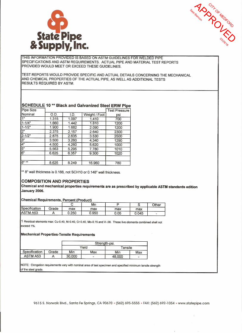
CITY O
F MED
FORD
APPRO
VED
Sam Barnum
03/29/18

CITY O
F MED
FORD
APPRO
VED
Sam Barnum
03/29/18