i. systems a vailable ii. installing the …. systems a vailable ii. installing the access system a....
TRANSCRIPT

ZICO®
3097PM6QUIC-LIFT™ HorIzonTaL Ladder & PorTabLe Tank SySTemS
modeL HLaS/modeL HPTSParTS and InSTrUCTIon manUaL REV. 6-13-17
I. SYSTEMS AVAILABLE
II. INSTALLING THE ACCESS SYSTEM
A. Preparation for Mounting B. Electrical System C. Mounting Suggestions
III. GENERAL INSTALLATION INFORMATION
A. Mounting Points B. Electrical Control Panel C. Ladder Control Panel
IV. STANDARD EQUIPMENT
A. Instruction Packet B. Electrical Control Panel C. Ladder/Tank Control Panel
V. OPTIONAL EQUIPMENT
A. Model LAS-LGK Ladder Guard Kit B. Installation Rung Wear Sleeve
VI. TROUBLESHOOTING
A. Excess Movement of the Rack and Ladders/Tank B. Rack Moving in a Jerking Motion or Stops
VII. MAINTENANCE
A. Periodic B. Semi-Annually or at Scheduled Apparatus Lube Service C. Replacing Hydraulic Fluid in the System D. Replacing the Hydraulic Cylinder E. Replacing the Latch Limit Switch F. Pressure Washing
VIII. SERVICE
IX. WARRANTY
X. DRAWINGS, DIAGRAMS AND CHARTS
A. Basic System B. Electrical System C. Hydraulic System
-1-

-2-
I. SYSTEMS AVAILABLE
Systems for ladders are made to order according to the ladders to be carried. In order to provide the System you require, we need to know the manufacturer, model number and length of ladders to be carried. The following models are available according to the nested depth of the ladder combinations:
• HLAS-975 Completefor9-3/4"laddercombo • HLAS-1200 Completefor12"laddercombo
Systemsforportablewatertanksaredesignedfortanksupto30"high.Specifythefollowingmodelnumber:
• HPTS
NOTE: The following restrictions apply to both Systems
• Systemsaredesignedforladdersnotexceeding35'inlength.
• Systemsarenotdesignedforladderswithbangersorpoles.
• Maximumweightofladders/tanksandotherequipmentcarriedontherackisnotto exceed500pounds.
The Systems are designed to operate in the following manner:
A. Thepowerswitchontheladder/tankcontrolpanelshouldbeturnedtothe"on"position.Thegreen lightwillcomeonindicatingpowertotheSystem.Pressandholddown,onthe"down"switch,tolower theSystem.Thelatch(9)willopenfreeingtheboomstobelowered.Thelatchiscontrolledbyanelectric actuator(11).Pressdownonthecontrolswitchuntiltheladders/tankareinthefulldownposition,parallel to the vehicle. The electrical actuator will close the latch at the end of the cycle.
B. Toraisetheunit,push"up"onthecontrolswitchandtheboomswillberaised.Attheendofthe cycle the latch will snap into place locking the booms in the closed position.
C. Thepowerswitchshouldbeturnedtothe"off"position(toconserveelectricalpower)whenthe ladders/tank are not required.
NOTE: Forallpartnumbersinparenthesis,refertoChart1,page26.

-3-
II. INSTALLING THE ACCESS SYSTEM
A. PreparationforMounting
The System has been tested at the factory prior to shipping. No additional adjustments should be required.However,theoverallheightoftheunit,includingthebooms,is56".Theboomsmayneedtobe cut down in length for your application. A can of touch-up paint is available for this purpose. See drawings below to determine the required dimensions.
SYM DESCRIPTION DIM.(MIN./MAX.)A shelf to bottom of ladder rack 38"/56"B shelf depth 12"/---C shelf width; door opening 15"/---D truck wall to bottom of rack (down pos.) 29-7/8"/47-7/8"
*
*
*customer to cut boom to length required to obtain proper truck clearance.
FIGURE1REQUIRED DIMENSIONSHLAS/HPTSSYSTEM
Holeswillneedtobedrilledinbothboomstoattachtheboomextensionweldments(leftandright). See Figure 2.
FIGURE2HOLE LOCATIONS
TOP OF BOOMS
BoomToTALLengTH=dim"A"-4/18"dim"A"=TruCkSHeLfToBoTTomofrACk(formuLAforreferenCeuSeonLy)

-4-
A. PreparationforMounting(continued)
Plan and lay out the entire installation before making any cuts or drilling holes in the body of the fireapparatus.Thiswillkeep"outofservice"timetoaminimumandalsohelptominimizemistakes.
Position the unit on the shelf of the apparatus and clamp it in place so that you can determine where the holes will be required for the mounting bolts. Also check to be sure there is an integral component of the body structure to attach the mounting bolts through. If there is no main frame member, you may have to adda1/2"thickaluminummountingplateandattachittoamainframemember.Placetheladdersor portable tank on top of the rack.
When the ladder or portable tank is raised and lowered in this position, it should clear protruding objects on the apparatus, such as emergency light, hand rails, etc. Make sure that when the ladders/tank are in the up position they do not obstruct cross lays on hose reels.
In the event that the booms come into contact with the stiffening rib at the top of the vertical hose bed wall, you may have to notch out the stiffening rib to recess the System. If the stiffening rib must be notched, the exposed metal surfaces should be painted and covered with an edge guard material. In addition, if the stiffening rib is notched, you may wish to add a backing plate on the inside surface of the hose bed wall. The plate will reinforce the hose bed wall and provide a good mounting support for the vertical mounting holes, if used. The edges of the mounting plate should be rounded off on the side next tothehose,andflatheadboltsshouldbeusedtomounttheplate.
Bolts3/8",orlarger,shouldbeusedtomountthebasecastingtothefireapparatus.Whentheunit willonlybemountedtothehosebedwalloronlytotheshelfdeck,1/2"boltsshouldbeusedwith substantial backing plates or attached to an integral component of the body structure.
A ladder stop must be provided which will prevent the ladders from swaying when in the stored position.Thestopmaybefabricatedusingthetopofthebodypanelasastartingpoint.Theactual"stop" will be up to the body manufacturer to fabricate unless the optional Zico HLAS Stop, HLAS-OS, is orderedwithyourunit(optionalstopshowninupperleftoffigure24,page30).
FIGURE 3LADDER STOP

-5-
A. PreparationforMounting(continued)
A mechanism for opening the door panel in front of the unit must also be fabricated by the apparatus manufacturer. The actual mechanism will depend on whether the door opens down or to the side. Contact the factory for suggestions.
B. Electrical System
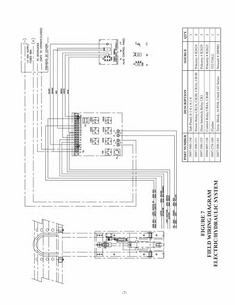
Now that you are sure of your mounting position, and the boom has been cut to the proper length, you maybegintolayouttheelectricalwiring(seefigure6,page6andfigure7,page7).Atthistimeitisa good idea to remove the unit from the apparatus shelf and clamp it to a work bench so that the booms can swingoutawayfromthebenchwhenlowered.unitshouldbemountedthesamedistancebackfromthe edge of the table as it would be on the shelf of your apparatus. Be sure the table is secured by adding a counterweight to the other side before lowering the unit. Determine where the wires can be run so they will not be visible from the outside of the apparatus. We recommend all electrical connections be soldered as this method is superior to crimp connections. We further recommend that a terminal block or quick disconnectbeattachedtothebasecasting.Wiresfromthehydraulicpowerunit(7),latchactuator(11)and limitswitch(89)shouldgointotheterminalblock.Thiswouldfacilitateservicetotheseitemsifrequired. Measure the required run lengths of the wires. (See Figure 6, page 6 and Figure 7, page 7 for proper wire diameter.)
Make up a wiring harness using wires longer than the required run lengths. Temporarily make all wire connections so you can test the system. With the table properly secured, you should be able to operate the unit.
Whentheflashinglightkit(modelHLAS-fLk)mustbeinstalled,thewiringdiagramandpartslists fortheflashinglightsmaybefoundonpages10and11,figures10and11.
C. RemovalofShippingPlug
Once the unit has been mounted to the apparatus, and the booms have been lowered completely, removetheShippingPluginthefrontofthereservoir(seefigure4)andinstalltheBreatherwithitsfilter facingdown(seefigure5).
FIGURE5FIGURE 4

-6-
FIG
UR
E 6
WIR
ING
DIA
GR
AM
ELECTRIC/HYDRAULICSYST
EM
-7-
PAR
T N
UM
BE
RD
ESC
RIP
TIO
NSO
UR
CE
QT
Y.3097-500-150
Sub-Panel,8-1/4x8-1/4
13097-500-151
Pow
er R
elay
CR
2A, C
R2B
, CR
3A, C
R3B
Pokorny#r2624
43097-500-155
Doo
r Int
erlo
ck R
elay
CR
1Pokorny#r2629
13094-005-156
Controlr
elayCr4A
,Cr4B
Poko
rny
# R
2622
23097-270-109
Flas
her
552/536LL
13097-500-181
Term.B
lock,16Po
S,Cinch141Series
New
ark
# 28
F881
1
FIG
UR
E 7
FIE
LD
WIR
ING
DIA
GR
AM
ELECTRIC/HYDRAULICSYST
EM

-8-
ITEM PART NUMBER DESCRIPTION QTY.1 3097-500-150 SuB-PAneL;81/4x81/4 12 diL-BLoXmoduLe 13 STAndoff#74096 24 SCreW,10-32x11/2PH 25 LoCkWASHer#10 106 HeXnuT,10-32 107 3097-500-151 PoWerreLAyCr2A,Cr2B,Cr3A,Cr3B 48 3097-500-155 doorinTerLoCkreLAyCr1 19 ConTroLreLAyCr4A,Cr4B 210 3097-270-109 FLASHER 111 fuSe7.5A 112 LOCKWASHER #6 413 HeXnuT,6-32 414 3097-500-181 Term.BLoCk;16PoS.CinCH141SerieS 115 SCreW;6-32x5/8rd.Hd. 416 Term.JumPerCinCHTyP141J 217 WIRING SET 118 TERMINAL LABEL 119 TERMINAL MARKING 1
FIGURE 8ELECTRICAL PANEL DIAGRAMELECTRIC/HYDRAULICSYSTEM

-9-
FIGURE 9HYDRAULIC CIRCUIT DIAGRAM

-10-
nfPA1901-96Standardrequiresflashinglightsbeprovided,facingfrontandrearofapparatus.Lightsmustcontinuetoflashwhilethedeviceisoutofthestoredposition.BeginningJanuary1,1997,allsystemsareprovidedwithflashinglights.Theaudio/visualalarmwillcontinuetobeofferedasanoption(seeSection8000fortheaudio/visualalarm).drilledandtappedholeshavebeenprovidedonQuiC-LifTSystemsshippedafterJanuary1,1997tomountthelightkits.
ITEMNO. PART NO. DESCRIPTION QTY.87 3097-270-101 Clearance Light 288 3097-270-106 Plate, Limit Switch* 189 3097-270-105 Switch, Limit 190 Harness,Limitswitch(includedwith89) 191 9025-191108 Screw,4-40x1/2"rd.Hd.Phil. 492 9025-191308 Screw,6-32x5/16"rd.Hd.Phil. 493 3097-270-111 CableTie6" 294 3097-270-113 In Line Splice 795 3097-510-110 16-2 Jacketed 2 Cond. Cable 1-6'96 3097-270-115 Snap Plug Connection* 497 3097-500-172 Straight conn., Plastic, 1/2 NPT* 198 8005-000-125 16 Ga. Lead Wire-Black 7.5'99 8005-000-130 16 Ga. Lead Wire-White 7.5'
FIGURE10PARTS & WIRING DIAGRAM
FLASHING LIGHT KIT
WIRING DIAGRAM LIGHTS TO BE MOUNTED ON FORWARD & REAR FACE OF LADDER RACK
*Installed on unit

-11-
WIRING SYSTEM:
1. Lights are to be mounted on forward and rear face of the rack.
2. Twosix-footlengthsofwire(95)areprovidedand installed, one for each light. Wires run on the inside of the rack.
3. onesix-footlengthofwire(95)providedtorun fromtheswitch(89)tothelightwires(95).This wire should run-up through the right boom.
4. Snapplugconnections(96)willbeattachedtoeach wire, ready to plug into lights prior to mounting.
FIGURE11WIRING SYSTEM
FLASHING LIGHT KIT

-12-
C. MountingSuggestions
A"WArning"label(partnumber3097-000-110)issuppliedwitheachQuiC-LifTSystem.The pressure sensitive or metal label must be mounted in close proximity to the ladder/tank control panel. All apparatus operators must be instructed to keep the area in front of the ladders/tank clear of personnel when the System is being raised or lowered.
Before starting the installation you should make sure you have all necessary tools and materials. This shouldincludematchingtouch-uppaint,edgetrim(forcutouts),fenderprotectorclothsandremovabletape (toprotectpaint),necessaryhardware,wireconnectors,cableties,burrremover,vacuumcleaner(formetal filings),loom(forwiring),drills,drillgun,wrenches,stepladders,etc.Besuretoallowyourselfsufficient timetomakeaproperinstallation.youwillprobablyhavetoremovethehosefromthehosebed.
NOTE: Thehydraulicpumpisdesignedforuseinthenormaloperatingtermpaturerangeof -20to+160degreesFahrenheit.Pleasereviewyourapplicationwiththefactoryfor usesbelow-20degrees.
Following these simple instructions should make your installation easy and professional.
III. GENERAL INSTALLATION INFORMATION
TheLadderAccessSystemswasdesignedforladdersmeetingthecurrentnfPA1931standard.Systemsaccommodatemostladdercombinations(seeSection1,under"noTe"forexceptions).
A. MountingPoints
The HLAS unit should be positioned so that an equal number of rungs of the ladder extend on either sideoftheladderrack.mountingholeshavebeenprovidedonboththeverticalandhorizontalmounting surfacesofthebasecasting.Althoughthedevicemaybesecurelymountedfromthehorizontalsurface only, it is a great advantage to be able to use mounting bolts on the vertical surface as well. The unit should be attached to an integral structural member of the vehicle. If this is not possible, then a one-half inch thick aluminumbackingplateshouldbeused.formounting,3/8"boltsshouldbeused.
B. Electrical Control Panel
The electrical control panel should be mounted in a water-proof compartment.
Several"Lockout"circuitsmaybeconsideredtopreventaccidentsfromoccurring.Anideal"Lock out"systemwouldonlypermitoperationwhentheignitionswitchison,thetransmissionisinpark,and any obstructing compartment doors are shut. Because of the higher amperage required to operate the System,aseparate"Lockout"circuitshouldbeused.The"Lockout"circuitshouldbeseparatedfromthe QuiC-LifTSystemcircuitbyarelay.Thiswillpreventdamagetotheexistingwiringsystem.The QuiC-LifTSystemcircuitshouldbeprotectedbyan80ampfuse(seefigure6,page6).

-13-
C. Ladder/TankControlPanel
The ladder/tank control panel should be mounted in such a position that the operator has full view of theQuiC-LifTSystemandpersonnelthatmightcomeincontactwithit(seefigure13,page14).
Panel should be mounted in a waterproof compartment. After all connections are complete and system has been tested, protect connections with a weather proofer like liquid tape.
WehaveextensivelytestedourQuiC-LifTSystemandhavefoundthenormallifetobeinexcessof 6,000cycleswithoutfailure.Withreasonablecareandmaintenance,yourSystemshouldgiveyoumany years of excellent service.
NOTE: Donotpermitpersonneltohang,sitorstandontherackorladderswhiletheyare storedontheQUIC-LIFTSystem.Permanentdamagemayresult.
IV. STANDARD EQUIPMENT
The following items are included with each complete System:
A. InstructionPacket
Includes all information required to install a complete System. Wiring diagrams and parts lists are provided.
B. ElectricalControlPanel(79)P/N3097-500-148
Complete panel ready for mounting.
FIGURE12OVERALL DIMENSIONS AND COMPONENTS
ELECTRICAL CONTROL PANEL

-14-
C. Ladder/TankControlPanel(80)P/N3097-500-170
Completepanelwithan"on"and"off"switchandindicatorlight,andan"up"and"down"switch, ready for mounting.
FIGURE13OVERALL DIMENSIONS AND COMPONENTS
LADDER/TANKCONTROLPANEL
ITEM PART NAME PART NUMBER QTY.Housing-medium8.375"Length 3097-165-125Housing-full10.5"Length 3097-145-125
81 Handle 3097-105-109 183 Spring 3097-105-113 184 Screw 1/2-13 x 6 1/2 Socket Hd 9010-3350104 1109 Setscrew-7/8-14HollowLock 3097-105-118 1110 ret.ring,1øext.(5100-100) 3097-105-121 1111 Wear Strip 3097-105-160 1112 Support, Retainer Handle 3097-180-105 1113 Screw,5/16-18x2SocketHd 9010-333132 185 Screw,5/16-18x31/2ScktHd.gr8 9018-103156 2100 Hexnut,5/16-18SelfLock 9013-133100 3
FIGURE14HANDLE ASSEMBLY
82 1
LT1 = PowerIndicatorLampP/N3097-500-158S2 = PowerSwitchP/N3097-500-157S1 = ControlSwitchP/N3097-500-156 Boot,ToggleSwitchP/N3097-105-145
NamePlate(red)3097-500-179SwitchPlate(alum.)3097-500-178
IMPORTANT:Slidetheladderlefttoright&checkforinterferencebetweentheretainerhandlesupports(112)andtherungsoftheladder.AZICOLadderGuideKit(Figure15)isrecommendedtohelpprotectagainstdamagetotheladderifthereisinterference.

-15-
V. OPTIONAL EQUIPMENT
The following items may be added to the HLAS Systems:
A. ModelLAS-LGKLadderGuardKit
The ladder guard kit contains one tube of epoxy and two stainless steel guards. The guards may be attached to the ladder rung to prevent wear and possible damage as a result of the locking handle's contact with the rung. The new handle assemblies have a replaceable plastic wear pad which should prevent damage to the rungs, but the ladder guard kit may also be required if unnecessary wear is noted.
Kitcontainsonetubeofepoxyandtwostainlesssteelrung
protectors.
Rungprotectorinstalledshowingproper placement.
FIGURE15LADDER GUARD KIT
B. InstallationRungWearSleeve
The small plastic sleeves may be purchased directly from the ladder manufacturer. The sleeves are pop-riveted to the rungs and prevent unnecessary wear on the rungs from constant rubbing on the side rails.
FIGURE16RUNG WEAR SLEEVE

-16-
VI. TROUBLESHOOTING
Allunitsaretestedafterfinalassemblytoensureproperoperationandadjustment.nofurtheradjustmentsshould be required unless excess movement is noted.
A. ExcessMovementoftheRackandLadders
If the rack and ladders appear to be moving more than when the System was initially installed, it is probably due to one of the following reasons:
1. Ladders and rack not properly seated against the vehicle mounted ladder stop.
A ladder stop must be provided by the apparatus manufacturer to prevent the ladders from swaying. If the ladder rack is not touching the stop, swaying will occur. Shims may be required to close the gap.
2. Booms move freely when the rack is pushed or pulled by hand.
usethefollowingprocedureforadjustingthehydrauliccylinder(8),bumpers(16)andlatch(9). Refer to Figures 17 and 18 on page 17 for numbers in parenthesis.
a. Remove ladders with the rack in the down position. Raise the unit back up approximately 3/4ofthewayandloosenthetwobumperlocknuts(65).Turnthebumpers(16)towardsthe backingplate(6).
b. raisetherackupuntilthecylinderisfullyextendedandthelatch(9)closes.Thehydraulic pump will slow down when the cylinder is fully extended.
c. Pullbooms(2and3)outbyhandtoapplyloadonthecylinder(8).
d. Checkthegapbetweentheinsidefaceofthelatch(9)andtheoutsidefaceofthelatch bar(10).
Thegapshouldbearound3/32"whenpullingoutontheboomassemblybyhandtotakethe freeplayoutoftheunit.ifthegapislessthan3/32",theoveralllengthofthecylinderhastobe lengthened.ifthegapismorethan3/32",theoveralllengthofthecylinderhastobemade shorter.
e. The length of the cylinder may be adjusted as follows:
1. Loosenthe3/8"socketheadcapscrewclampboltontheshaftclevispin.
2. Lowertheracksothelatch(9)opensandthelatchbar(10)justclearsthelatch.This takes the pressure off the cylinder which will make the next step easier.

-17-
A. ExcessMovementoftheRackandLadders(continued)
3. Turn the cylinder shaft in the appropriate direction to lengthen or shorten it.
WARNING: Donotuseapipewrenchorvisegrips.Damagetothecylindershaft willoccur.Theshaftwillalmostalwaysturnbyhand.Rubbercoated workgloveswillincreaseyourgrip.
f. Afterturningtheshaftabout1/4turn,raisetheunitbackup.donottightentheclevisclamp bolt at this time.
g. makesurethecylinderisfullyextendedandre-checkforthe3/32"gapwhilepullingouton the boom assemblies.
FIGURE17FRONT VIEW
FIGURE18SIDE VIEW
h. Afterthe3/32"gapisachieved,tightentheclevisclampboltandturnthebumpersuntilthey aretouchingthebasecasting(1).maintainoutwardpressureontheboomwhileyouarehand tightening the bumper.
i. Lower the unit a few inches. Turn the bumpers out one full turn away from the backing plate.re-tightenthebumperlocknuts(65).
j. Raise the unit back up to full cylinder extension. Listen for the pump to slow down. The gapbetweentheinsidefaceofthelatch(9)andtheoutsidefaceofthelatchbar(10)shouldnow be1/64"to3/64"andtheunitwillbetight.

-18-
B. RackMovinginaJerkingMotionorStops
1. Checkfluidlevelinthehydraulicpump.
2. followfillingprocedure(Vii.C.1.).
VII. MAINTENANCE
A. Periodic
1. Anytimetheladderrackandladdersappeartosway,refertoTroubleshooting(Vi.A.)and followsuggestionsdependinguponyourspecificproblem.
2. Visuallyinspecthydraulicsystemforleaksindicatedbythepresenceofhydraulicfluidorthe accumulationofdirtaroundafitting.refertoCheckingHydraulicfluidLevel(Vii.B.2.)before proceeding.
3. Visually inspect the plastic pads for wear. Pads are located at several points on the ladder rack assemblyandaredesignedtominimizeweartotheladders.replaceasrequired.
B. Semi-AnnuallyoratScheduledApparatusLubeService
TheaboveitemsunderPeriodicmaintenanceshouldbecheckedfirstandthenproceedasfollows:
1. Lubricate the following parts as indicated.
a. Joints and pivot points should be sprayed with CRC brand Stor&Lub long term lubricant andrustpreventative#03032.excesslubricationshouldbewipedoff.
b. Hydraulic ram is self-lubricating and should require no additional lubrication.
c. greasefittingsarelocatedonthebottomofthelowershaft(4),oneoneachsideunderthe booms,andthereisoneadditionalgreasefittinginthelowercylinderpin(57).usechassis lube at these three points.
d. Latchbar(10)andlatch(9)shouldbelubricatedwithdoorjamgreasewherethetwoparts come together.

-19-
FIGURE19HYDRAULIC SYSTEM COMPONENTS
B. Semi-AnnuallyoratScheduledApparatusLubeService(continued)
2. Checkinghydraulicfluidlevel.
Hydraulic system is a closed loop system. Noone,otherthanaqualifiedhydraulicpump technician,shouldattempttoremoveanyfittingsorhosesfromthesystem.Thesystemcontains oneorificewhichisrestrictedto.025"(30).Removalofthisfittingcouldcausebodilyinjury. SeelocationonFigure22.
a. The booms must be lowered completely to view oil level in reservoir.
b. removeelbow(48)andBreatherfilterfromfrontofreservoir.

-20-
B. Semi-AnnuallyoratScheduledApparatusLubeService(continued)
c. ViewoillevelthroughBreather/fillPort.oilshouldbe3/8"to1/4"belowthebottomofthe Port.
d. If oil needs to be added, Zico recommends:
SAe5W20,orothercleanhydraulicoilwithaviscosityof150to 300SuSat100degreesfahrenheit.Systemcapacity(dry)is 50ounces.
C. ReplacingHydraulicFluidintheSystem
Thewholeproceduremaytakeonetotwohours.Havereplacementreservoirsealand50ouncesof fluidavailablebeforestartingthejob.Hydraulicfluidinthissytemmaybeunderpressure.Always wearsafetyglassesandprotectiveclothingandusethefollowingproceduretochangethefluid:
1. Lower the booms and remove the ladder rack and ladders.
2. Slowlyremovethehydrauliclinesfromthefittingsonthefrontsideofthepump.Seefigure22.
3. Disconnect the electric wires to the hydraulic pump.
4. removethetwobolts(45)andlockwashers(73)holdingthepowerunitmountingbar(32)to thebasecasting(1)andremovethepowerunit(7).
5. Clampthemountingbar(32)inavisewiththepumpheldintheverticalposition(sameas mountedposition).
6. Withthepumpmountedinthevise,removetheBreatherelbow(48)andBreather.releasethe pump from the vise and drain oil into a pan via the Breather/Fill Hole. Loosen and remove the two screws holding the reservoir to the pump. Clean reservoir.
7. Checkthetwofilterscreensinthebottomofthepumpandcleanifnecessary.
8. Place the two open hydraulic lines into a receptacle. Raise and lower the booms by hand to blow thefluidfromthehydrauliccylinder(8).
CAUTION: Controltheraisingandloweringofthebooms.Donotallowthemtodrop uncontrolled.

-21-
C. ReplacingHydraulicFluidintheSystem(continued)
9. replacereservoirontothebottomofthepumpusingnewseal.replaceandtightenscrews holding reservoir to pump.
10. re-attachthepumpontothebasecastingandre-attachthehydrauliclinesandelectricpower.
11. Put32ouncesoffreshhydraulicfluidintothepumpthroughtheBreather/fillHole.
12. runtheboomsupanddownthreeorfourtimes.Bleedairfromthelinesthefirsttime.Wait approximately5minutesand,withtheboomsdown,checkthefluidlevel.Approximately18ounces offluidwillhavebeenreplacedintothelinesandhydrauliccylinder.
13. Add14ouncesoffluidtothereservoir,cyclesystemafewmoretimes,andthenrecheckoil level.1/8"to1/4"belowportisgood.
14. Acoupleofmoreouncesoffluidmayhavetobeaddedtobringthefluidup.Whenthefulllevel is obtained, reinstall Breather Elbow and Breather. Oil change complete.
D. ReplacingtheHydraulicCylinder
elbowadapterfittings(30&31)areprovidedonreplacementhydrauliccylinders.The elbow adapterwithrestrictedorifice(30)shouldnotberemovedfromthecylinderforanyreason. Wearing safety glasses and protective clothing, you may use the following procedure to change the hydraulic cylinder:
1. makesurethelatch(9)issecurelyinplace.Asaprecaution,securetheboomstotheapparatus so they cannot come down on their own.
2. removethefluidlines(seefigure19,page19)fromtheelbowadapterfittings.Do not removetheelbowfittingsfromthecylinder.Placetheopenendsofthefluidlinesintoa receptacletocatchthefluid.
3. Loosen the socket head cap screw on the lower side of the top clevis clamp. Note cylinder to clevis relationship.
4. removepin(57)fromthelowerclevisclamp.
5. Turnthecylindercounterclockwisetoremovethecylinderramfromthetopclevisclampyoke.
6. Replace the cylinder and turn clockwise to re-attach the cylinder ram into the top clevis clamp yoke.
7. replacepin(57)throughthelowerclevisclamp.
8. re-tightenthesocketheadcapscrewonthelowersideofthetopclevisclamp;reattachthe hydraulic lines, and remove the device used to secure the booms to the vehicle in step 1.

-22-
D. ReplacingtheHydraulicCylinder(continued)
9. CAuTion:Thefollowinginstructionswillleaveboomrackuncontrolled.manualcontrolof boom will be necessary via fork lift or overhead crane. When ready, unlatch latch and lower boom all the way.
10. removeBreatherelbow(48)andBreather.Addoiltoreservoiruptobottomofport.
11. Slightlyloosenthefittingonthebottomofthecylinder.runthepumpuptoblowairoutofthe upline.retighten,andwiththepumpraiseboomallthewayup.Additionaloilmaybeneededto achieve this.
12. Slightlyloosenthefittingatramendofcylinderandrunthepumptobleedairfromtheline. Retighten and run the system Down all the way.
13. Addoiltothereservoiruntilitis1/4"to3/8"belowthefillPort.runsystemafewmoretimes, allowing air to settle out. Check oil level. When level is acceptable reinstall the Breather Elbow and Breather.
14. Checkthegapbetweenthelatch(9)andlatchbar(10).ifthegapis1/64"to3/64",youare done. If the gap is greater than this range, you will need to follow the steps under VI. A. 2. (page16)tore-adjustthelengthofthecylinderram.
E. Replacing Latch Limit Switch
The following procedure may be used to replace the latch limit switch:
1. Lowertheboomstogainaccesstothelimitswitch(12).
2. Remove the old switch. Match the new switch to the old and set the roller follower arm on the same angle.
3. Mount the new switch.
4. Withtheboomsupandthelatchactuatorretracted,liftuponthefrontofthelatch(9)and listen for the latch limit switch to click. It should click when the bottom front side of the latch is approximately1/4to3/8"abovethetopsurfaceofthelatchbarcasting.
5. Toadjusttherollerfollowerarm,loosentheAllencapscrewthatlocksthisarminplace.move thisarmuntiltheswitchclickswiththe1/4to3/8"clearance.
F. PressureWashing
Do not operate pressure washer around or near the hydraulic pump. Excessive pressure may allow soap and water to blow past the seal, damaging the hydraulic cylinder.
VIII. SERVICE
ifyouexperienceanyproblemswithyourHorizontalAccessSystem,pleasecallusat800-711-3473forassistance. Please have the serial number of your system available. This number may be found on metal plate riveted to the base casting.

-23-
IX. WARRANTY
AcopyofthewarrantyregistrationmuSTbereturnedtoZiCotoensureregistrationofyourSystem(seebackcover).
X. DRAWINGS, DIAGRAMS AND CHARTS
A. Basic System
1. CompletepartsphotosforHLAS/HPTS(figure21,page27throughfigure24,page30)
2. ChartofHLAScomponentparts(Chart1,page26)
3. CompletepartslistinganddrawingforHPTS(figure20,pages24and25)
4. Spacerequirementforsystem(figure1,page3)
5. Changinglengthofbooms(figure2,page3)
6. Ladderstop(figure3,page4)
7. Handleassembly(figure14,page14)
8. Ladderguardkit(figure15,page15)
9. rungwearsleeve(figure16,page15)
10. Adjustmentproceduretoarrestexcessivemovement(figures17&18,page17)
B. Electrical System
1. electricalcontrolpanelwithmountingdimensions(figure12,page13)
2. Ladder/Tankcontrolpanelwithmountingdimensions(figure13,page14)
3. electricaldiagrams(figure6,page6andfigure7,page7)
4. flashinglightkit(figure10,page10andfigure11,page11)
5. Latchlimitswitch(seeVii.e.,page22,figure22,page28)
C. HydraulicSystem
1. Pumpandhydraulicsystem(figure19,page19)
2. restrictedorificefitting(figure19,page19)

-24-
ITEM NO. PART NO. DESCRIPTION QTY.1 3098-200-101 Rack Weldment 12 3098-200-102 Safety Stop Bracket 23 3098-200-104 Quick Release Strap Belt 24 3097-500-415 Adjustable Side Guard 45 9018-103744 Screw,3/8-16x23/4HH,C/Sgr8 46 9113-173700 Nut, 3/8-16 Nylon Lock Hex SS 47 9114-103700 Flatwasher, 3/8 SS 88 9018-102514 Screw,1/4-20x7/8HH,C/Sgr8 49 9113-172500 nut,1/4-20nylonLock,HexSS 410 9114-102500 flatwasher,1/4SS 811 3097-500-421 uprightWearSleeves 412 9018-103156 Screw,5/16-18x31/2,HHgr8 813 9014-113100 flatwasher,5/16nom 1614 9014-203100 Lockwasher,5/16nom 815 9113-103100 Hexnut,5/16-18 8
FIGURE20COMPONENTS FOR
MODEL HPTS PORTABLE TANK SYSTEM

-25-

-26-
12345678910111213141516171819
212223242526272829303132333435
*363738394041
42
4344
454647
484950515253545556
3097-500-1013097-500-1033097-500-1053097-500-1153097-500-1093097-500-1113097-500-1923097-500-1983097-500-1933097-500-1213097-500-1853097-500-1813097-500-1873097-500-1893097-500-1913097-500-1133097-500-1953097-605-1963097-500-4073097-500-4193097-500-4203097-500-4503097-500-4183097-500-4153097-500-4213097-500-1353097-500-1333097-500-1323097-500-1343097-500-1293097-500-1253097-500-1243097-500-1903097-500-1623097-500-1649018-1043209018-104372NOT PROVIDED9010-2213109010-2213189010-1025249018-103156
9018-363128
9010-1637489018-103744
9010-1037129010-1037169018-103772
3097-500-1949010-1031489010-3831080000-025-1079080-0025169080-0025209080-0025289080-0050403097-500-226
Base CastingBoom-Left HandBoom-Right HandLower Shaft, Boomuppermtg.BlockCasting,Cyl.BackingPlate,uppermtg.Blk.Powerunit,HydraulicHyd.Cyl.2.5"x8"StrokeLatchLatch BarActuator,Latch1øx1"StrokeLimit Switch, LatchLatchSpringHousing-upperLatch Spring Housing-LowerLatch SpringBumper, Mech. StopBoom Ext Weldment-LeftBoom Ext Weldment-RightLadder Rack WeldmentSafetyLoop,15"o.A.L.SafetyLoop,13"o.A.L.Sleeve,SafetyLoop-28-1/2"Lg.Bracket, Safety LoopAdjustable Ladder Side GuarduprightWearSleeves-8-3/4"elbow,PutoHose(7/16-20)HydflexHose-Short-203/4"LHydflexHose-Long-29"L1/4odHydLineAssy.Hydraulic Fluid, 1 Qt. NSelbow/Adapterw/orificeElbow/Adaptermtg.Bar,PowerunitSpindrivegreasefitting-1/4-28Spindrivegreasefitting-1/4-2845°Screw,7/16øx1-1/4HHSZPgr8Screw,7/16øx4HHSZPgrade8Base Mounting Screws NSScrew,#6-32x5/8PanHdSZPScrew, #6-32 x 1-1/8 Pan Hd SZPScrew,1/4-20x1-1/2"HexHdScrew,5/16-18x3-1/2"HxHd SZP Grade 8Screw,5/16-18x1-3/4"flatHd SZP Grade 8Screw, 3/8-16 x 3 FH-Phil SZPScrew,3/8-16x2-3/4"HexHd SZP Grade 8Screw,3/8-16x3/4"HexHdSZPScrew, 3/8-16 x 1 Hex Hd SZPScrew,3/8-16x4-1/2"HexHdSZP Grade 8Plastic ElbowScrew,5/16-18x3HexHdSZPSetscrew5/16-18x1/2"CupPt.PlatedBoot, RedClevisPin,1/4øx1Lg.SZPClevisPin,1/4øx1-1/4Lg.SZPClevisPin,1/4øx1-3/4Lg.SZPClevis Pin, 1/2ø x 2-1/2 Lg. SZPCylinderPin,1"ø(upper)
1111111111111112111
1244211111111244
12221
12
2
84
444
121211111
ITEM PART NO. DESCRIPTION QTY.
20 2
575859606162636465666768697071727374757778798081
8384858687888990919293949596979899100101103104105106107109110111112113114115116117118
3097-500-1269070-0006089070-0012129070-0015249014-1143009113-1725009013-1331009012-1037009012-1050009012-1543009014-1131009014-1137009014-1150009014-2013003097-500-1999014-2031009014-2037009014-2050009014-2043003097-500-1413097-500-1453097-500-1483097-500-1703097-105-1093097-165-1253097-145-1253097-105-1139010-33501129018-1031723097-105-1163097-270-1013097-270-1063097-270-205
9025-1911089025-1913053097-270-1113097-270-1133097-510-1103097-270-1153097-500-1728005-000-1258005-000-1309013-1331003097-500-1603097-290-1053097-500-4233097-500-4253097-500-4273097-500-1743097-105-1183097-105-1213097-105-1603095-180-1059010-3331323097-500-1423097-105-1303097-105-1623097-500-1833097-500-455
CylinderPin,1"ø(Lower)Cotter Pin, 1/6 x 1/2CotterPin,1/8x3/4CotterPin5/32x1-1/2Flatwasher, 7/16 ID SZPLocknut,1/4-20SZPHexnut,5/16-18SZPHex Nut, 3/8-16 SZPHex Nut, 1/2-13 SZPHexnut,7/16-14SZPflatwasher,5/16idSZPFlatwasher, 3/8 ID SZPFlatwasher, 1/2 ID SZPLockwasher, #6 SZPPlug, ShippingLockwasher,5/16idSZPLockwasher, 3/8 ID SZPLockwasher, 1/2 ID SZPLockwasher, 7/16 ID SZPHelicalBundlingWrap-21"LatchAct.2WireHarness-7.5'Elec. Panel AssemblySwitch Panel AssemblyHandle, Ladder RetainerretainerHousing-medium-8.25"LretainerHousing-full-10.50"LCompression SpringSocket Hd Screw, 1/2-13 x 7Screw,5/16-18x41/2SocketHd,gr8Wear PadsClearance Light Plate, Limit SwitchLimit SwitchHarness,LimitSwitch(includedw/89)Screw,#4-40x1/2SelfTaprndHdScrew,#6-32x5/16SelfTaprndHdCableTie,6"In Line Splice16-2 Jacketed 2 Cond CableSnap Plug ConnectorStraight Conn., Plastic, 1/2 NPT16 Ga Lead Wire - Black16 Ga Lead Wire - Whitenut,SelfLocking5/16-18Ladder Rack Rubber BumperPaint,Touchup,12oz.CanLabel, "danger, loss of hyd. fluid"Label, "warning, pinching of fingers"Label, "warning, striking injury"Cap,Plastic-3/4ønom.Setscrew,7/8-14HollowLockRet. Ring, 1ø Ext.Wear StripSupport, Retainer HandleScrew,5/16-18x2SocketHeadBoom End Cap, PlasticnylonWasher,1/2idx3/4odx.062Label, "to prevent wear"tag, "caution remove plug"innerSleeve,SafetyLoop1-1/2"idx2"
131281
122048242244114222811112
224821114226
(3)6'417'7'102111122222422112
ITEM PART NO. DESCRIPTION QTY.
NS(8)(9)
NSNS
(6)(6)
NSNS
NS
NS
282
nS-notShownonfigures21to24*Indicates New Item( )-Seefigure_____Labels Not Shown
CHART1HLAS PARTS LISTING

-27-
FIGURE21HYDRAULIC COMPONENTS

-28-
MODEL HLASCOMPONENT PARTS -
HORIZONTAL LADDERACCESS SYSTEM
FIGURE22HYDRAULIC AND ELECTRICAL
LATCH COMPONENTS

-29-
FIGURE23BOOM COMPONENTS
See Detail

-30-
FIGURE24END OF BOOM AND RACK COMPONENTS
OptionalStop(soldseparately)
Important: DO NOT bolt through these wear pads(86).ifaboltis needed here, use a flathead,countersunkscrew under the pad.

-31-
Ziamatic Corp.10WestCollegeAvenue,P.O.Box337,Yardley,PA19067-0587 • (215)493-3618 • FAX:(215)493-1401
*ZICOisaregisteredtrademarkforfire,safetyandmarineproductsmadebyZiamaticCorp. CopyrightZiamaticCorp.6-17
www.ziamatic.comTOLLFREE: 800-711-3473

-32-
WARRANTY REGISTRATION
PLeaSe emaIL [email protected] or Fax a CoPy To 866-493-1401 To regISTer yoUr UnIT
firedePArTmenTnAme: ______________________________________ ConTACTPerSon: _______________________________
PHoneno.: ______________________________________ fAXno.: ______________________________________________________
STreeT AddreSS: _____________________________________________________________ P.o. BoX: ________________________
CiTy: ______________________________________________________ STATe ______________ ZiP: ______________________
modeLno.:(CHeCkone) ___________ HLAS-975 ___________ HLAS-1200 ___________ HPTS
SeriALno.onuniT:(SeePAge27forLoCATion) __________________________________________________
inSTALLedon:(VeHiCLemfg.) ____________________________________ deLiVered:(dATe) _________________________
WASuniTinSTALLedon: __________ neWVeHiCLe __________ reTrofiTTedonToeXiSTingVeHiCLe
LAdderSmounTedonTHeuniT:
duoSAfeTy _________ fT.eXTenSion,modeL _________ ALCoLiTe _________ fT.eXTenSion,modeL _________
duoSAfeTy _________ fT.roof,modeL _______________ ALCoLiTe _________ fT.roof,modeL _______________
duoSAfeTy _________ fT. __________,modeL _________ ALCoLiTe _________ fT.__________,modeL __________
oTHer(mfg.) __________________________________________________
____________ fT.eXTenSion,modeL ____________
____________ fT.roof,modeL __________________
____________ fT. __________,modeL ____________
WHeredidyouHeArABouTourProduCT?
__________ mAgAZineAd(SPeCify) ________________________________________________________________________________
__________ deALer(SPeCify) ______________________________________________________________________________________
__________ VeHiCLemfg.(SPeCify) ________________________________________________________________________________
__________ AnoTHerdePArTmenT(SPeCify) _______________________________________________________________________
__________ oTHer(SPeCify) _______________________________________________________________________________________