i revision summary
TRANSCRIPT
Service Bulletin 13-022 ~ Applies To: 1998-2003 Civic GX - ALL with SCI CNG Fuel Tank Assembly
2004-2011 Civic GX - ALL June 24, 2015
• 2012-2015 Civic Natural Gas-ALL
CNG Fuel Tank Solenoid Valve Replacement Process (Supersedes 13-022, dated March 29, 2013, to revise the information marked by the black bars)
REVISION SUMMARY
I Under Applies To, 2014-2015 model years were added. Under PARTS INFORMATION, the phone number was changed.
BACKGROUND
For vehicles with SCI compressed natural gas (CNG) fuel tanks, Honda is no longer replacing the fuel tank and solenoid valve altogether. If you replace the fuel tank solenoid valve, you must now reinstall the original fuel tank.
All SCI aluminum fuel tanks are eligible for fuel tank solenoid replacement, but you must first get Tech Line authorization.
This service bulletin does not apply to Lincoln Composite fuel tanks, which must still be replaced as a remanufactured assembly. (Refer to Service Bulletin 01-005, CNG Fuel TankAssemblyln-Warranty Exchange Program.) Check the fuel tank label to confirm that the tank is from SCI.
REPAIR POLICY Repairs on CNG fuel tank assemblies may require the installation of a new CNG fuel tank solenoid valve assembly.
© 2015 American Honda Motor Co., Inc. -All Rights Reserved
PARTS INFORMATION
NOTE: To help clarify where new parts are used in the REPAIR PROCEDURE, the new part is listed in the applicable repair step with a ">" symbol.
Front Upper Tum Clip (2 required): PIN 91561-SJD-003
Fuel Line Connector O-Ring (1/4 in. Port Side) (2 required):
PIN 91066-SlG-A0l
Fuel Line Connector O-Ring (3/8 in. Port Side): PIN 91066-SlG-B0l
Fuel Line Connector O-Ring (1/4 in.)(5 required): PIN 91067-SlG-A0l
Fuel Line Connector O-Ring (3/8 in.)(2 required): PIN 91067-SlG-B0l
Fuel Tank Solenoid Valve: PIN 16750-RNE-A0l
Fuel Tank Solenoid Valve O-Ring: PIN 17574-PDN-A0l
NOTE: If you are ordering this part for replacement by a service facility that is not your dealer, you will need to report the name and address of the shop as well as the VIN of the vehicle on which the valve will be installed to Tech Line. You will need the Tech Line reference number to order the replacement CNG fuel tank solenoid valve and O-ring from Tech Line at 800-824-6632. • Other parts listed are available through the normal parts ordering process
REQUIRED MATERIALS
Contact I Brake Cleaner: PIN 08700-9201
Nitrogen Bottle 240 cu ft (filled to 1,500 psi): ( commercially available)
PAG Oil: PIN 38897-Pl3-A01AH
Plastic Wire Tie: (commercially available)
Snoop Liquid Leak Detector: (order from swagelok.com)
48532-02087 Version 3 1 of 15
Skill Level CUSTOMER INFORMATION: The information in this bulletin is intended for use only by skilled technicians who have the proper tools, equipment, and training to correctly and safely maintain your vehicle. These procedures should not be attempted by "do-it-yourselfers," and you should not assume this bulletin applies to your vehicle, or that your vehicle has the condition described. To determine whether this information applies, contact an authorized Honda automobile dealer.
R REPAIR

TOOL INFORMATION
CNG Tank Valve Replacement Kit: TIN HONCNGKIT
Kit contains: Knurled Threaded Handle Mini Gator Clamp Molykote 55 grease Negative/Positive Gator Clamp
Pin Spanner Receptacle Gauge Steel Braided Line Yellow Paint Marker Ground Wire Manual Override Vent Tool
Vent Tube
Available for loan from the Honda Tool And Equipment Program at 888-424-6857.
Vernier Caliper: ( commercially available)
WARRANTY CLAIM INFORMATION
The normal warranty applies.
OP# Description FRT
3101S4 Remove and reinstall the CNG fuel tank.
A Replace CNG fuel tank solenoid valve.
Failed Part:
Defect Code:
Symptom Code:
Skill Level:
DIAGNOSIS
PIN 16750-RNE-A0l
03217
09001
Repair Technician (Honda NGV Certified)
5.6
1.0
NOTE: You must be a Honda NGV-Certified Technician to do the fuel tank solenoid valve inspection or replacement work.
1. Follow the normal troubleshooting procedures found in the service manual or on ISIS. If your troubleshooting leads you to suspect the solenoid valve assembly is faulty, go to step 2
2. Call Tech Line to assist and confirm the diagnosis that a fuel tank solenoid valve assembly replacement is necessary. You will need a Tech Line reference number to place the order for the replacement fuel tank solenoid valve assembly and the fuel tank O-ring.
2 of 15
REPAIR PROCEDURE
A WARNING Compressed natural gas is flanunable and highly explosive. You could be killed or seriously injured if leaking natural gas is ignited.
Stop the engine, and keep heat, sparks and flames away.
When venting fuel, follow local regulations concerning venting natural gas. Consult your local fire and environmental authorities for specific regulations. This procedure should be done outside, in a well ventilated area, or in a properly equipped NGV shop.
Check for a gas leak if there is an odor coming from the vehicle. Compressed natural gas can only be smelled, not seen.
NOTE: Safety glasses need to be worn during these operations.
The following service manual procedures have been used in full or in part within this service bulletin. For more detail on these procedures, and torque specifications for some components, refer to the appropriate service manual, or view them online.
• Fuel Pressure Relieving
• Fuel Tank Removal and Installation
• Fuel Joint Block Removal and Installation
• Rear Floor Undercover Removal and Installation
• Rear Floor Upper Crossmember Gusset Removal and Installation
• C-Pillar Trim Removal and Installation
• Rear Seat Belt Removal and Installation
• Rear Seat-back Removal and Installation
• Rear Floor Undercover Removal and Installation
Relieve the Fuel Tank Pressure Vent the fuel pressure from the fuel tank with the CNG Vent Tool set. Refer to the Fuel Pressure Relieving procedure in the service manual under the "Fuel and Emissions" section.
NOTE:
• Using the tank venting tool to relieve tank pressure makes the solenoid valve unusable and it must be replaced with a new valve.
• Do not use the fuel stem to relieve pressure on the fuel receptacle line. If the fuel stem is removed, it must be replaced with a new one.
13-022

Remove the Fuel Tank Assembly from the Vehicle 1. Remove the fuel tank assembly from the vehicle as
described in the applicable service manual. Online, enter keywords FUEL TANK, and select the appropriate procedure.
2. Position the four rubber blocks from the CNG tank valve replacement kit under the fuel tank frame and side rail. The joint block should be suspended above the ground.
JOINT BLOCK BLOCKS
3. Use the large plastic wire tie to support the fuel joint block lines up to the frame. Make sure that the joint block bracket is attached. Leave the wire tie in place until the lines are reattached to the new solenoid valve.
NOTE: Do not overtighten the wire tie. This will cause pressure on the fuel lines and may cause problems aligning them to the new fuel tank valve.
13-022
Remove the Tank Solenoid Valve 1. Loosen the large seal boot clamp. Pull the clamp
and the vent boot aside far enough to be able to disconnect the two-pin connector from the tank solenoid valve pigtail harness.
SUB HARNESS CLIP
LARGE SEAL BOOT
3 of 15

2. Fold back the seal boot to access the fuel lines.
NOTE: Use an elastic cord to hold the seal boot out of the way.
3. Loosen and remove the three fuel line nuts from the connector fittings. Remove the O-rings. Support the line connector on the valve with a wrench while loosening the line nut.
NOTE: Always use two wrenches when removing or installing the fuel line nuts.
O-RING
SOLENOID VALVE PIGTAIL HARNESS
'
4. Disconnect the solenoid valve pigtail harness from the backing plate clip.
5. Gently pull the fuel lines back slightly so you can remove the fuel line connectors.
NOTE: Be careful not to bend the fuel lines because they will not realign properly if bent.
4 of 15
FUEL LINE CONNECTORS (Retain.)
O-RINGS (Replace.)
6. Note the position of the line connectors. Remove the three fuel line connectors.
NOTE: There are two smaller fittings. The one with the shorter threads goes into the middle position of the solenoid valve for the pressure relief valve.
7. Position the 2.5-inch socket from the kit over the valve, with the pigtail harness coiled on the end of the solenoid valve in order to fit it inside the socket.
2.5-INCH SOCKET
13-022

8. Use the breaker bar supplied in the kit to loosen the solenoid valve.
DANGER: If the valve does not turn easily, the tank has pressure in it. Stop and do the tank venting procedure again. Do not proceed until there is no pressure in the tank and the valve turns easily.
BREAKER BAR
9. Remove the solenoid valve by hand and remove the 0-ring.
(Replace.)
SOLENOID VALVE
10.
13-022
11. Install the fuel tank stand support tool, and the threaded tipping handle from the kit. With the help of another technician, stand the tank on its end and allow it to drain for 20 minutes. Place a clean and empty drain pan underneath the tank to catch any liquid as proof of contaminated CNG.
NOTE: If any liquid is found in the tank, replace both filters. Any water in the fuel tank indicates fuel contamination and warranty consideration would not apply. Discuss your findings with your DPSM or Tech Line.
MOISTURE FROM TANK
12. Return the tank to the horizontal position.
5 of 15

Evaluate the New Replacement Solenoid Valve Condition before Installing 1. Visually inspect the fuel tank solenoid valve for
damage to the threaded area, the O-ring seat area, the wiring, and the connector.
> Fuel Tank Solenoid Valve
Inspect wiring.
Inspect wiring.
2. Connect the solenoid valve test harness from the kit to the solenoid valve 2-pin connector.
3. Using a DVOM, test the resistance of the new solenoid valve. It should be 18 to 21 ohms.
• If the solenoid valve is within specification, go to step 4.
• If the solenoid valve is not within specification, obtain a new solenoid valve, and retest.
TEST HARNESS
\
DVOM
6 of 15
4. Momentarily connect the test harness to an automobile battery or booster pack, and electrically activate the solenoid valve.
• If the solenoid valve works properly, and you can see the solenoid plunger operate, go to step 5.
• If the solenoid valve does not work properly, obtain a new solenoid valve, and retest.
5. After confirming proper operation, the valve is ready for installation.
BATTERY
13-022
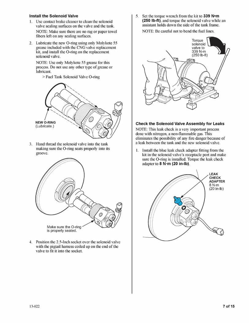
Install the Solenoid Valve 1. Use contact brake cleaner to clean the solenoid
valve sealing surfaces on the valve and the tank.
NOTE: Make sure there are no rag or paper towel fibers left on any sealing surfaces.
2. Lubricate the new O-ring using only Molykote 55 grease included with the CNG valve replacement kit, and install the O-ring on the replacement solenoid valve.
NOTE: Use only Molykote 55 grease for this process. Do not use any other type of grease or lubricant.
> Fuel Tank Solenoid Valve O-ring
3. Hand thread the solenoid valve into the tank making sure the O-ring seats properly into its groove.
Make sure the 0-ring is properly seated.
4. Position the 2.5-Inch socket over the solenoid valve with the pigtail harness coiled up on the end of the valve to fit it into the socket.
13-022
5. Set the torque wrench from the kit to 339 N•m (250 lb-ft), and torque the solenoid valve while an assistant holds down the side of the tank frame.
NOTE: Be careful not to bend the fuel lines.
Check the Solenoid Valve Assembly for Leaks NOTE: This leak check is a very important process done with nitrogen, a non-flammable gas. This eliminates the possibility of any fire danger because of a leak between the tank and the new solenoid valve.
1. Install the blue leak check adapter fitting from the kit in the solenoid valve's receptacle port and make sure the O-ring is installed. Torque the leak check adapter to 8 N·m (20 in-lb).
LEAK CHECK ADAPTER 8 N-m (20 in-lb)
7 of 15

2. Install the nitrogen gas regulator supplied in the kit onto the gas cylinder, and make sure the regulator key is unscrewed most of the way without removing it.
NOTE: Always wear safety glasses when working with pressure.
NITROGEN GAS REGULATOR
GAS CYLINDER
REGULATOR KEY
3. Connect the high pressure hose from the kit to the solenoid valve adapter and the gas regulator. Make sure the nitrogen tank is supported safely.
8 of 15
HIGH PRESSURE HOSE
NITROGEN TANK
SOLENOID VALVE ADAPTER
4. Open the main nitrogen cylinder valve number 1:
• Tum the regulator key number 2 clockwise to set the regulator to 400 PSI.
• When the hissing stops, the tank is fully pressurized.
Open the main ~'1' nitrogen cylinder \..V valve.
~
/ ~ Turn the regulator key until
the gauge reads 400 psi.
13-022

5. To check the solenoid valve O-ring for leaks, apply Snoop Liquid Leak Detector at the base of the solenoid valve. Check for bubbles around the O-ring seal. Use only Snoop Liquid Leak Detector because the nitrogen will not be detected by an electronic detector.
• If there are no bubbles, go to step 7.
• If there are bubbles, go to step 6.
6. Call Tech Line for a procedure to release the nitrogen from the fuel tank without damaging it, then remove the solenoid valve. Check the sealing surfaces for debris, and clean as necessary and do the following:
• Check the sealing surface of the valve. If it is damaged, replace the valve and the O-ring.
• Replace the O-ring with a new one.
• Reinstall the solenoid valve, repeat step 3 through 5 to check for leaks.
7. If no leaks are found, close the nitrogen cylinder valve, loosen the regulator key, and slowly loosen the hose fitting at the fuel tank adapter to bleed off pressure in the hose. Only a small amount of gas should be released when breaking the seal on the hose.
• If gas continues to vent, the solenoid check valve is defective. Remove and replace the solenoid valve and O-ring with a new one, then repeat the leak check procedure.
• If nitrogen pressure does not leak continuously when the line is cracked open, remove the high pressure hose and the adapter fitting from the solenoid valve.
NOTE: The nitrogen will remain in the tank.
13-022
8. Install new O-rings on the three connectors. First apply tape over the connector threads to keep from scratching the O-rings while installing them. After installation, remove the tape, and lubricate the O-rings with PAG oil.
> Fuel Line Connector O-ring (1/4 in. Port Side) (2)
> Fuel Line Connector O-ring (3/8 in. Port Side)
9 of 15
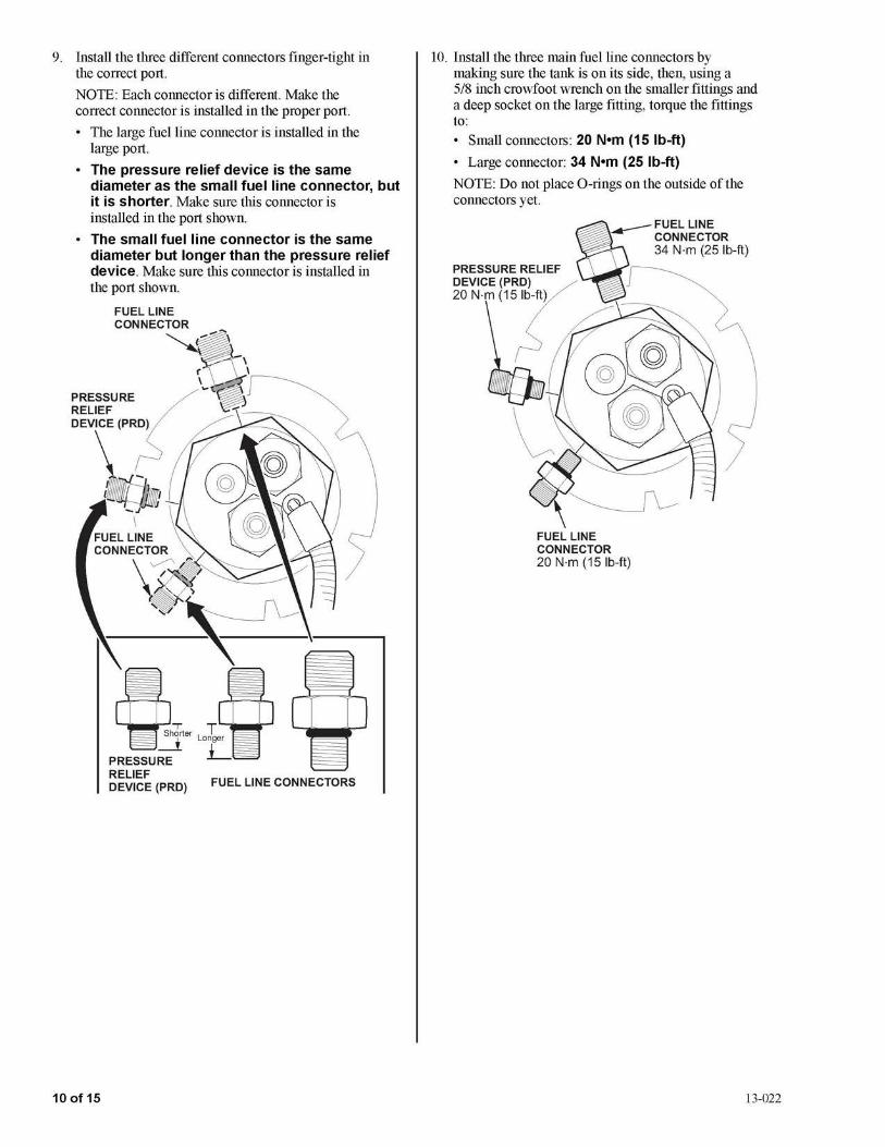
9. Install the three different connectors finger-tight in the correct port.
NOTE: Each connector is different. Make the correct connector is installed in the proper port.
• The large fuel line connector is installed in the large port.
• The pressure relief device is the same diameter as the small fuel line connector, but it is shorter. Make sure this connector is installed in the port shown.
• The small fuel line connector is the same diameter but longer than the pressure relief device. Make sure this connector is installed in the port shown.
10 of 15
Jl_r~,LT............,.. ~ anger
PRESSURE L RELIEF DEVICE (PRD) FUEL LINE CONNECTORS
10. Install the three main fuel line connectors by making sure the tank is on its side, then, using a 5/8 inch crowfoot wrench on the smaller fittings and a deep socket on the large fitting, torque the fittings to: • Small connectors: 20 N•m (15 lb-ft)
• Large connector: 34 N•m (25 lb-ft)
NOTE: Do not place O-rings on the outside of the connectors yet.
FUEL LINE CONNECTOR 20 N-m (15 lb-ft)
13-022
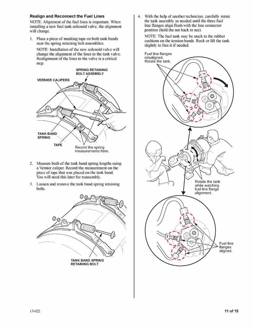
Realign and Reconnect the Fuel Lines NOTE: Alignment of the fuel lines is important. When installing a new fuel tank solenoid valve, the alignment will change.
1. Place a piece of masking tape on both tank bands near the spring retaining bolt assemblies.
NOTE: Installation of the new solenoid valve will change the alignment of the lines to the tank valve. Realignment of the lines to the valve is a critical step.
SPRING RETAINING BOLT ASSEMBLY
VERNIER CALIPERS I
Record the spring measurements here.
2. Measure both of the tank band spring lengths using a Vernier caliper. Record the measurement on the piece of tape that was placed on the tank band. You will need this later for reassembly.
3. Loosen and remove the tank band spring retaining bolts.
13-022
TANK BAND SPRING RETAINING BOLT
4. With the help of another technician, carefully rotate the tank assembly as needed until the three fuel line flanges align flush with the line connector position (hold the nut back to see).
NOTE: The fuel tank may be stuck to the rubber cushions on the tension bands. Rock or lift the tank slightly to free it if needed.
Fuel line flanges aligned.
11 of 15

5. Lubricate the three O-rings with PAG oil, then install them on the connectors.
> Fuel Line Connector O-ring (1/4 in.)(2)
> Fuel Line Connector O-ring (3/8 in.)
6. While holding the fuel line tight against the fitting, first, hand tighten the nut, then torque the line nuts to make sure the O-ring does not get mis-aligned and damaged. Torque to:
• Small connectors: 27 N•m (20 lb-ft)
• Large connector: 47 N•m (35 lb-ft)
7. Use a back up wrench on the connector fitting when tightening.
SMALL CONNECTOR LINE NUTS 27 N-m (20 lb-ft)
LARGE CONNECTOR LINE NUT 47 N-m (35 lb-ft)
8. Make sure the tank does not shift when reinstalling the tank band spring retaining bolt assemblies. Tighten them until the spring length is the same as previously recorded.
NOTE: Make sure the new alignment is correct before tightening the tank bands.
12 of 15
9. Make sure the vertical lines on the tank align with the tank bands.
NOTE: After the new solenoid valve is installed, if the marks are rotated to the rear, align them with the tank bands in the rear, then make new marks on the side of the tank that will face the trunk opening.
VERTICAL LINES
TANK
TANK BANDS
10. Install and torque the spring retaining bolt lock nuts to 38 N•m (28 lb-ft).
13-022
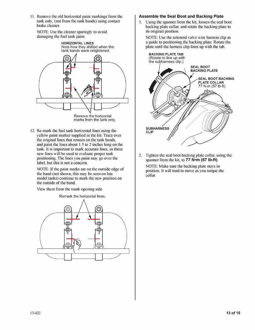
11. Remove the old horizontal paint markings from the tank only, (not from the tank bands) using contact brake cleaner.
NOTE: Use the cleaner sparingly to avoid damaging the fuel tank paint.
HORIZONTAL LINES Note how they shifted when the tank bands were retightened.
Remove the horizontal marks from the tank only.
12. Re-mark the fuel tank horizontal lines using the yellow paint marker supplied in the kit. Trace over the original lines that remain on the tank bands, and paint the lines about 1.5 to 2 inches long on the tank. It is important to mark accurate lines, as these new lines will be used to evaluate proper tank positioning. The lines you paint may go over the label, but this is not a concern.
NOTE: If the paint marks are on the outside edge of the band (not shown, this may be seen on late model tanks) continue to mark the new position on the outside of the band.
View them from the trunk opening side
Remark the horizontal lines.
13-022
Assemble the Seal Boot and Backing Plate 1. Using the spanner from the kit, loosen the seal boot
backing plate collar, and rotate the backing plate to its original position.
NOTE: Use the solenoid valve wire harness clip as a guide to positioning the backing plate. Rotate the plate until the harness clip lines up with the tab.
2. Tighten the seal boot backing plate collar, using the spanner from the kit, to 77 N•m (57 lb-ft).
NOTE: Make sure the backing plate stays in position. It will tend to move as you torque the collar.
13 of 15
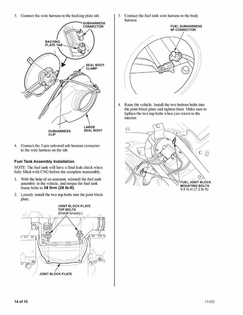
3. Connect the wire harness to the backing plate tab.
SUBHARNESS CLIP
LARGE SEAL BOOT
4. Connect the 2-pin solenoid sub harness connector to the wire harness on the tab.
Fuel Tank Assembly Installation
NOTE: The fuel tank will have a final leak check when fully filled with CNG before the complete reassembly.
1. With the help of an assistant, reinstall the fuel tank assembly in the vehicle, and torque the fuel tank frame bolts to 38 N•m (28 lb-ft).
2. Loosely install the two top bolts into the joint block plate.
JOINT BLOCK PLATE
14 of 15
3. Connect the fuel tank wire harness to the body harness.
4. Raise the vehicle. Install the two bottom bolts into the joint block plate and tighten them. Make sure to tighten the two top bolts when you return to the interior.
13-022
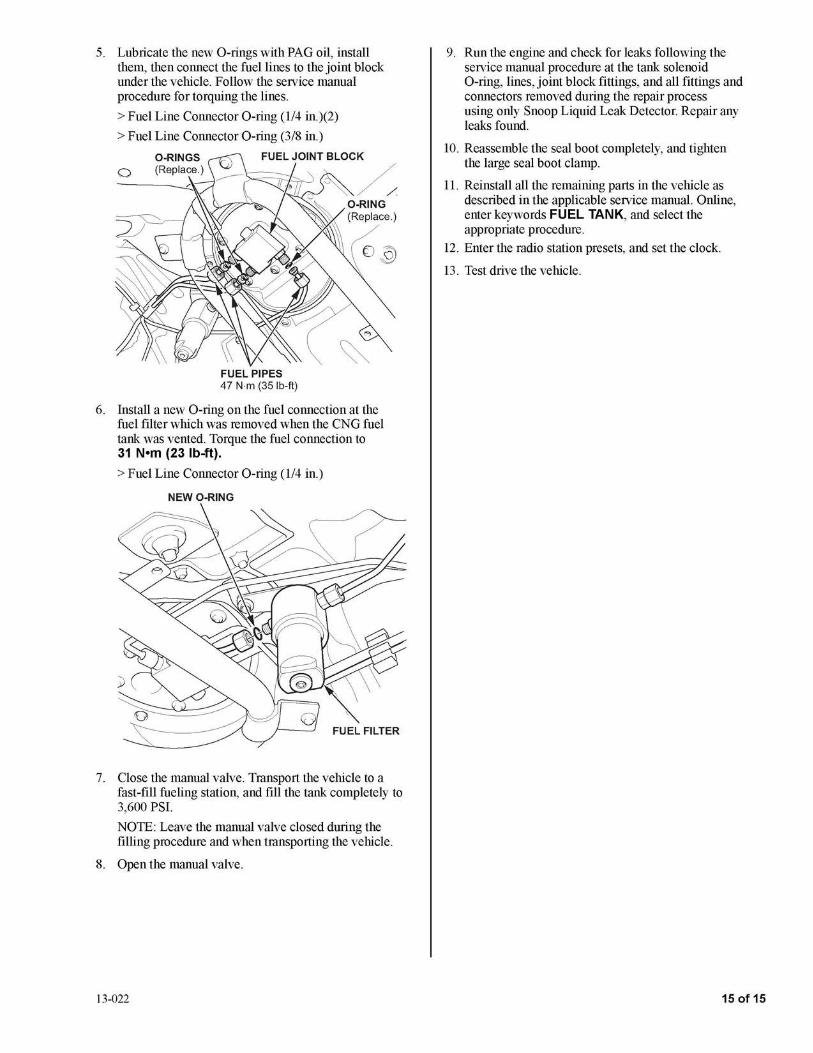
5. Lubricate the new O-rings with PAG oil, install them, then connect the fuel lines to the joint block under the vehicle. Follow the service manual procedure for torquing the lines.
> Fuel Line Connector O-ring (1/4 in.)(2)
> Fuel Line Connector O-ring (3/8 in.)
FUEL PIPES 47 N-m (35 lb-ft)
6. Install a new O-ring on the fuel connection at the fuel filter which was removed when the CNG fuel tank was vented. Torque the fuel connection to 31 N•m (23 lb-ft).
> Fuel Line Connector O-ring (1/4 in.)
NEWO-RING
FUEL FILTER
7. Close the manual valve. Transport the vehicle to a fast-fill fueling station, and fill the tank completely to 3,600 PSI.
NOTE: Leave the manual valve closed during the filling procedure and when transporting the vehicle.
8. Open the manual valve.
13-022
9. Run the engine and check for leaks following the service manual procedure at the tank solenoid O-ring, lines, joint block fittings, and all fittings and connectors removed during the repair process using only Snoop Liquid Leak Detector. Repair any leaks found.
10. Reassemble the seal boot completely, and tighten the large seal boot clamp.
11. Reinstall all the remaining parts in the vehicle as described in the applicable service manual. Online, enter keywords FUEL TANK, and select the appropriate procedure.
12. Enter the radio station presets, and set the clock.
13. Test drive the vehicle.
15 of 15