i r - drum
TRANSCRIPT

ISR develops, applies and teaches advanced methodologies of design and analysis to solve complex, hierarchical,heterogeneous and dynamic problems of engineering technology and systems for industry and government.
ISR is a permanent institute of the University of Maryland, within the Glenn L. Martin Institute of Technol-ogy/A. James Clark School of Engineering. It is a National Science Foundation Engineering Research Center.
Web site http://www.isr.umd.edu
I RINSTITUTE FOR SYSTEMS RESEARCH
TECHNICAL RESEARCH REPORT
Basic Concepts and Taxonomy of Dependable and Secure Computing
by Algirdas Avizienis, Jean-Claude Laprie, Brian Randell,Carl Landwehr
TR 2004-47
Basic Concepts and Taxonomy of Dependable and Secure Computing
Algirdas Avizienis Vytautas Magnus
University, Kaunas, Lithuania
and UCLA, Los Angeles, CA
USA [email protected] [email protected]
Jean-Claude Laprie LAAS-CNRS
Toulouse France
Brian Randell School. of Computing
Science Univ. of Newcastle upon
Tyne UK
Carl Landwehr Institute for Systems
Research University of Maryland,
MD USA
Abstract This paper gives the main definitions relating to dependability, a generic concept including as special case such attributes as reliability, availability, safety, integrity, maintainability, etc. Security brings in concerns for confidentiality, in addition to availability and integrity. Basic definitions are given first. They are then commented upon, and supplemented by additional definitions, which address the threats to dependability and security (faults, errors, failures), their attributes, and the means for their achievement (fault prevention, fault tolerance, fault removal, fault forecasting). The aim is to explicate a set of general concepts, of relevance across a wide range of situations, and so to help communication and cooperation among a number of scientific and technical communities, including ones that are concentrating on particular types of system, of system failures, or of causes of system failures.
Index Terms: Dependability, security, trust, faults, errors, failures, vulnerabilities, attacks, fault tolerance, fault
removal, fault forecasting
1. Introduction
This paper aims to give precise definitions characterizing the various concepts that come into play when
addressing the dependability and security of computing and communication systems. Clarifying these concepts is
surprisingly difficult when we discuss systems in which there are uncertainties about system boundaries.
Furthermore, the very complexity of systems (and their specification) is often a major problem, the determination
of possible causes or consequences of failure can be a very subtle process, and there are (fallible) provisions for
preventing faults from causing failures.
Dependability is first introduced as a global concept that subsumes the usual attributes of reliability,
availability, safety, integrity, maintainability, etc. The consideration of security brings in concerns for
confidentiality, in addition to availability and integrity. The basic definitions are then commented upon, and
supplemented by additional definitions. Boldface characters are used when a term is defined, while italic
characters are an invitation to focus the reader’s attention.
This paper can be seen as an attempt to document a minimum consensus on concepts within various specialties
in order to facilitate fruitful technical interactions; in addition, we hope that it will be suitable a) for use by other
bodies (including standardization organizations), and b) for educational purposes. Our concern is with the
concepts: words are only of interest because they unequivocally label concepts, and enable ideas and viewpoints to
be shared. An important issue, for which we believe a consensus has not yet emerged, concerns the measures of

2
dependability and security; this issue will necessitate further elaboration before being documented consistently
with the other aspects of the taxonomy that is presented here.
The paper has no pretension of documenting the state-of-the-art. Thus, together with the focus on concepts, we
do not address implementation issues such as can be found in standards, for example in [IEC 1998] for safety or
[ISO/IEC 1999] for security.
The dependability and security communities have followed distinct, but convergent paths: a) dependability has
realized that restriction to non-malicious faults was addressing only a part of the problem, b) security has realized
that the main focus that was put in the past on confidentiality needed to be augmented with concerns for integrity
and for availability (they have been always present in the definitions, but did not receive as much attention as
confidentiality). The paper aims to bring together the common strands of dependability and security although, for
reasons of space limitation, confidentiality is not given the attention it deserves.
Preceding Work and Goals for the Future
The origin of this effort dates back to 1980, when a joint committee on “Fundamental Concepts and
Terminology” was formed by the TC on Fault-Tolerant Computing of the IEEE CS and the IFIP WG 10.4
“Dependable Computing and Fault Tolerance”. Seven position papers were presented in 1982 at a special session
of FTCS-12 [FTCS 1982], and a synthesis was presented at FTCS-15 in 1985 [Laprie 1985] which is a direct
predecessor of this paper, but provides a much less detailed classification, in particular of dependability threats
and attributes.
Continued intensive discussions led to the 1992 book Dependability: Basic Concepts and Terminology [Laprie
1992], which contained a 34-page English text with an eight-page glossary and its translations into French,
German, Italian, and Japanese. The principal innovations were the addition of security as an attribute and of the
class of intentional malicious faults in the taxonomy of faults. Many concepts were refined and elaborated.
The next major step was the recognition of security as a composite of the attributes of confidentiality, integrity
and availability and the addition of the class of intentional non-malicious faults, together with an analysis of the
problems of inadequate system specifications [Laprie 1995], though this account provided only a summary
classification of dependability threats.
The present paper represents the results of a continuous effort since 1995 to expand, refine and simplify the
taxonomy of dependable & secure computing. It is also our goal to make the taxonomy readily available to
practitioners and students of the field, therefore this paper is self-contained and does not require reading of the
above mentioned publications. The major new contributions are:
1) the relationship between dependability and security is clarified (sec. 2.3)
2) a quantitative definition of dependability is introduced (sec. 2.3);
3) the criterion of capability is introduced in the classification of human-made non-malicious faults (sec. 3.2.1,
3.2.3), enabling the consideration of competence;
4) the discussion of malicious faults is extensively updated (sec. 3.2.4);
5) service failures (3.3.1) are distinguished from dependability failures (sec. 3.3.3): the latter are recognized when
service failures over a period of time are too frequent or too severe;
6) dependability issues of the development process are explicitly incorporated into the taxonomy, including partial
and complete development failures (sec. 3.3.2);

3
7) the concept of dependability is related to dependence and trust (sec. 4.2), and compared with three recently
introduced similar concepts, including survivability, trustworthiness, high-confidence systems (sec. 4.4).
After the present extensive iteration, what future opportunities and challenges can we foresee that will prompt
the evolution of the taxonomy? Certainly, we recognize the desirability of further:
• expanding the discussion of security, for example to cover techniques for protecting confidentiality,
establishing authenticity, etc.,
• analyzing issues of trust and the allied topic of risk management,
• searching for unified measures of dependability and security.
We expect that some challenges will come unexpectedly (perhaps as so-called “emergent properties”, such as
those of the HAL computer in Arthur C. Clarke's “2001: A Space Odyssey”) as the complexity of man-machine
systems that we can build exceeds our ability to comprehend them. Other challenges are easier to predict:
1) New technologies (nanosystems, bio-chips, chemical and quantum computing, etc.) and new concepts of man-
machine systems (ambient computing, nomadic computing, grid computing, etc.) will require continued
attention to their specific dependability issues.
2) The problems of complex human-machine interactions (including user interfaces) remain a challenge that is
becoming very critical — the means to improve their dependability and security need to be identified and
incorporated.
3) The dark side of human nature causes us to anticipate new forms of maliciousness that will lead to more forms
of malicious faults and hence requirements for new defenses as well.
In view of the above challenges and because of the continuing and unnecessarily confusing introduction of
purportedly “new” concepts to describe the same means, attributes and threats, the most urgent goal for the future
is to keep the taxonomy complete to the extent that this is possible, but at the same time as simple and well-
structured as our abilities allow.
2. The Basic Concepts
In this section we present a basic set of definitions that will be used throughout the entire discussion of the
taxonomy of dependable & secure computing. The definitions are general enough to cover the entire range of
computing and communication systems, from individual logic gates to networks of computers with human
operators and users. In what follows we focus mainly on computing and communications systems, but our
definitions are also intended in large part to be of relevance to computer-based systems, i.e., systems which also
encompass the humans and organizations that provide the immediate environment of the computing and
communication systems of interest.
2.1. System Function, Behavior, Structure, and Service
A system in our taxonomy is an entity that interacts with other entities, i.e., other systems, including hardware,
software, humans, and the physical world with its natural phenomena. These other systems are the environment of
the given system. The system boundary is the common frontier between the system and its environment.
Computing and communication systems are characterized by fundamental properties: functionality,
performance, dependability & security, and cost. Other important system properties that affect dependability and
security include usability, manageability, and adaptability – detailed consideration of these issues is beyond the
4
scope of this paper. The function of such a system is what the system is intended to do and is described by the
functional specification in terms of functionality and performance. The behavior of a system is what the system
does to implement its function and is described by a sequence of states. The total state of a given system is the set
of the following states: computation, communication, stored information, interconnection, and physical condition.
The structure of a system is what enables it to generate the behavior. From a structural viewpoint, a system is
composed of a set of components bound together in order to interact, where each component is another system,
etc. The recursion stops when a component is considered to be atomic: any further internal structure cannot be
discerned, or is not of interest and can be ignored. Consequently, the total state of a system is the set of the
(external) states of its atomic components
The service delivered by a system (in its role as a provider) is its behavior as it is perceived by its user(s); a
user is another system that receives service from the provider. The part of the provider’s system boundary where
service delivery takes place is the provider’s service interface. The part of the provider’s total state that is
perceivable at the service interface is its external state; the remaining part is its internal state. The delivered
service is a sequence of the provider’s external states. We note that a system may sequentially or simultaneously
be a provider and a user with respect to another system, i.e., deliver service to and receive service from that other
system. The interface of the user at which the user receives service is the use interface.We have up to now used
the singular for function and service. A system generally implements more than one function, and delivers more
than one service. Function and service can be thus seen as composed of function items and of service items. For
the sake of simplicity, we shall simply use the plural — functions, services — when it is necessary to distinguish
several function or service items.
2.2. The Threats to Dependability and Security: Failures, Errors, Faults
Correct service is delivered when the service implements the system function. A service failure, often
abbreviated here to failure, is an event that occurs when the delivered service deviates from correct service. A
service fails either because it does not comply with the functional specification, or because this specification did
not adequately describe the system function. A service failure is a transition from correct service to incorrect
service, i.e., to not implementing the system function. The period of delivery of incorrect service is a service
outage. The transition from incorrect service to correct service is a service restoration. The deviation from
correct service may assume different forms that are called service failure modes and are ranked according to
failure severities. A detailed taxonomy of failure modes is presented in Section 3.
Since a service is a sequence of the system’s external states, a service failure means that at least one (or more)
external state of the system deviates from the correct service state. The deviation is called an error. The adjudged
or hypothesized cause of an error is called a fault. Faults can be internal or external to system. The prior presence
of a vulnerability, i.e., an internal fault that enables an external fault to harm the system, is necessary for an
external fault to cause an error, and possibly subsequent failure(s). In most cases a fault first causes an error in the
service state of a component that is a part of the internal state of the system and the external state is not
immediately affected.
For this reason the definition of an error is: the part of the total state of the system that may lead to its
subsequent service failure. It is important to note that many errors do not reach the system’s external state and
cause a failure. A fault is active when it causes an error, otherwise it is dormant.
5
When the functional specification of a system includes a set of several functions, the failure of one or more of
the services implementing the functions may leave the system in a degraded mode that still offers a subset of
needed services to the user. The specification may identify several such modes, e.g., slow service, limited service,
emergency service, etc. Here we say that the system has suffered a partial failure of its functionality or
performance. Development failures and dependability failures that are discussed in Section 3.3 also can be partial
failures.
2.3. Dependability, Security, and their Attributes
The original definition of dependability is: the ability to deliver service that can justifiably be trusted. This
definition stresses the need for justification of trust. The alternate definition, that provides the criterion for
deciding if the service is dependable, is: the dependability of a system is the ability to avoid service failures that
are more frequent and more severe than is acceptable.
It is usual to say that the dependability of a system should suffice for the dependence being placed on that
system. The dependence of system A on system B thus represents the extent to which system A’s dependability is
(or would be) affected by that of System B. The concept of dependence leads on to that of trust, which can very
conveniently be defined as accepted dependence.
As developed over the past three decades, dependability is an integrating concept that encompasses the
following attributes:
• availability: readiness for correct service;
• reliability: continuity of correct service;
• safety: absence of catastrophic consequences on the user(s) and the environment;
• integrity: absence of improper system alterations;
• maintainability: ability to undergo modifications, and repairs.
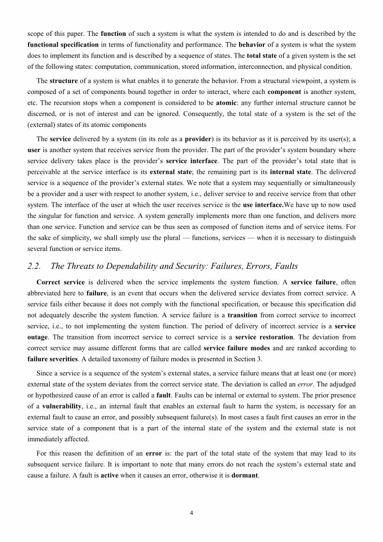
When addressing security, an additional attribute has great prominence, confidentiality, i.e., the absence of
unauthorized disclosure of information. Security is a composite of the attributes of confidentiality, integrity and
availability, requiring the concurrent existence of a) availability for authorized actions only, b) confidentiality, and
c) integrity with ‘improper’ meaning ‘unauthorized’.
Figure 2.1 summarizes the relationship between dependability and security in terms of their principal attributes.
The picture should not be interpreted as indicating that, for example, security developers have no interest in
maintainability, or that there has been no research at all in the dependability field related to confidentiality —
rather it indicates where the main balance of interest and activity lies in each case.
Figure 2.1: Dependability and security attributes SecurityDependability
AvailabilityReliability
Safety
ConfidentialityIntegrity
Maintainability
The dependability & security specification of a system must include the requirements for the attributes in
terms of the acceptable frequency and severity of service failures for specified classes of faults and a given use
environment. One or more attributes may not be required at all for a given system.
6
2.4. The Means to Attain Dependability and Security
Over the course of the past fifty years many means have been developed to attain the various attributes of
dependability and security. Those means can be grouped into four major categories:
• fault prevention: means to prevent the occurrence or introduction of faults;
• fault tolerance: means to avoid service failures in the presence of faults;
• fault removal: means to reduce the number and severity of faults;
• fault forecasting: means to estimate the present number, the future incidence, and the likely consequences of
faults.
Fault prevention and fault tolerance aim to provide the ability to deliver a service that can be trusted, while
fault removal and fault forecasting aim to reach confidence in that ability by justifying that the functional and the
dependability & security specifications are adequate and that the system is likely to meet them.
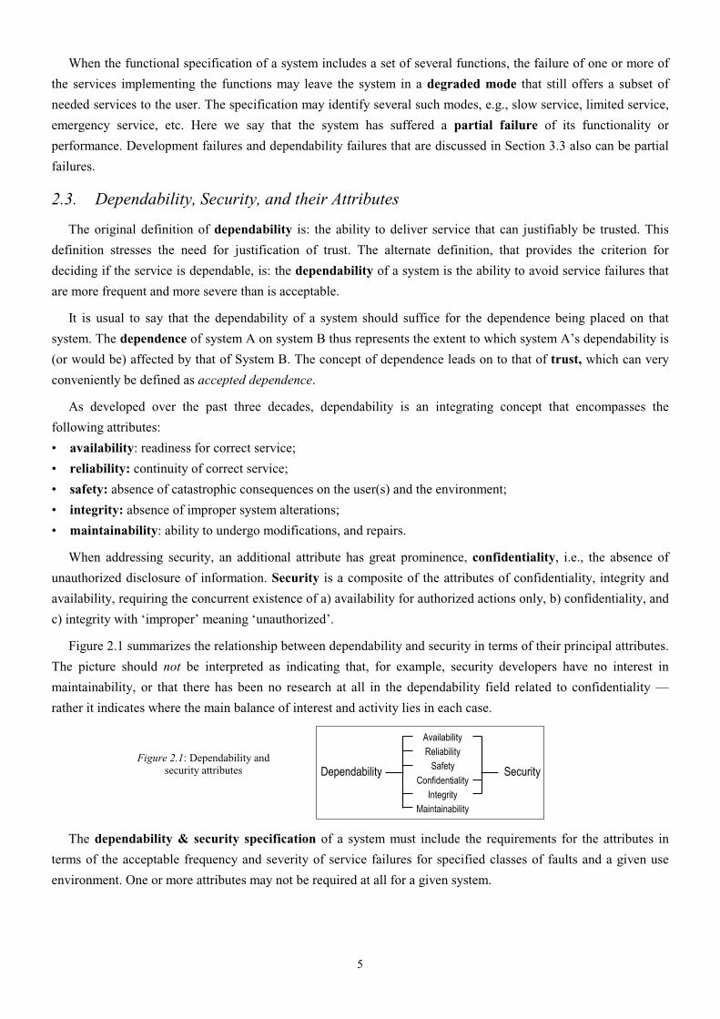
2.5. Summary: the Dependability and Security Tree
The schema of the complete taxonomy of dependable & secure computing as outlined in this section is shown
in Figure 2.2.
Figure 2.2: The dependability and security tree Dependability
andSecurity
Attributes
Threats
Means
Availability
Reliability
Safety
Confidentiality
Integrity
Maintainability
Faults
Errors
Failures
Fault Prevention
Fault Tolerance
Fault Removal
Fault Forecasting
3. The Threats to Dependability and Security
3.1. System Life Cycle: Phases and Environments
In this section we present the taxonomy of threats that may affect a system during its entire life. The life cycle
of a system consists of two phases: development and use.
The development phase includes all activities from presentation of the user’s initial concept to the decision
that the system has passed all acceptance tests and is ready to deliver service in its user’s environment. During the
development phase the system interacts with the development environment and development faults may be
introduced into the system by the environment. The development environment of a system consists of the
following elements:
1. the physical world with its natural phenomena;
2. human developers, some possibly lacking competence or having malicious objectives;
3. development tools: software and hardware used by the developers to assist them in the development process;
4. production and test facilities.

7
The use phase of a system’s life begins when the system is accepted for use and starts the delivery of its
services to the users. Use consists of alternating periods of correct service delivery (to be called service delivery),
service outage, and service shutdown. A service outage is caused by a service failure. It is the period when
incorrect service (including no service at all) is delivered at the service interface. A service shutdown is an
intentional halt of service by an authorized entity. Maintenance actions may take place during all three periods of
the use phase.
During the use phase the system interacts with its use environment and may be adversely affected by faults
originating in it. The use environment consists of the following elements:
1. the physical world with its natural phenomena;
2. administrators (including maintainers): entities (humans or other systems) that have the authority to manage,
modify, repair and use the system; some authorized humans may lack competence or have malicious objectives;
3. users: entities (humans or other systems) that receive service from the system at their use interfaces;
4. providers: entities (humans or other systems) that deliver services to the system at its use interfaces;
5. the infrastructure: entities that provide specialized services to the system, such as information sources (e.g.,
time, GPS, etc.), communication links, power sources, cooling airflow, etc.
6. intruders: malicious entities (humans and other systems) that attempt to exceed any authority they might have
and alter service or halt it, alter the system’s functionality or performance, or to access confidential
information. Examples include hackers, vandals, corrupt insiders, agents of hostile governments or
organizations, and malicious software.
As used here, the term maintenance, following common usage, includes not only repairs, but also all
modifications of the system that take place during the use phase of system life. Therefore maintenance is a
development process, and the preceding discussion of development applies to maintenance as well. The various
forms of maintenance are summarized in Figure 3.1.
Figure 3.1: The various forms of maintenance
Maintenance
CorrectiveMaintenance
PreventiveMaintenance
AdaptiveMaintenance
AugmentiveMaintenance
Removal ofreported faults
Discovery and removal of
dormant faults
Adjustment toenvironmental
changes
Augmentationof system’s
function
Repairs Modifications
It is noteworthy that repair and fault tolerance are related concepts; the distinction between fault tolerance and
maintenance in this paper is that maintenance involves the participation of an external agent, e.g., a repairman, test
equipment, remote reloading of software. Furthermore, repair is part of fault removal (during the use phase), and
fault forecasting usually considers repair situations. In fact, repair can be seen as a fault tolerance activity within a
larger system that includes the system being repaired and the people and other systems that perform such repairs.
3.2. Faults
3.2.1. A Taxonomy of Faults
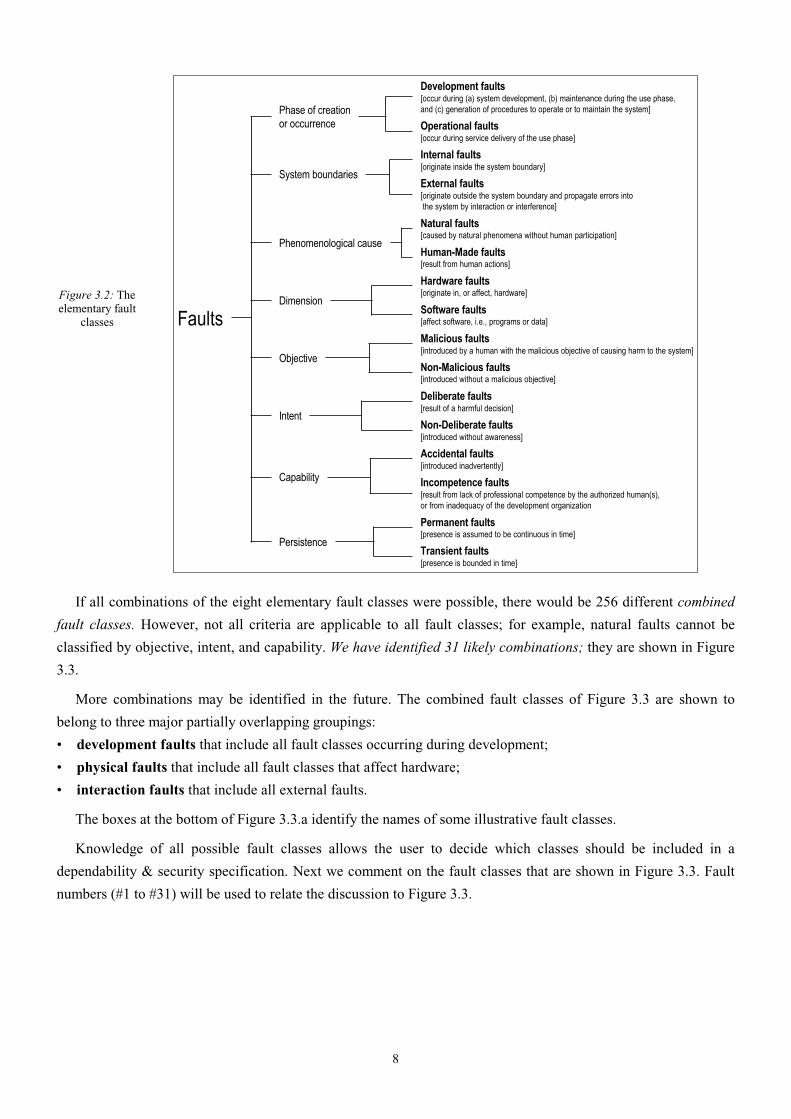
All faults that may affect a system during its life are classified according to eight basic viewpoints, leading to
the elementary fault classes, as shown in Figure 3.2.
8
Figure 3.2: The elementary fault
classes
Faults
Phase of creationor occurrence
Development faults[occur during (a) system development, (b) maintenance during the use phase, and (c) generation of procedures to operate or to maintain the system]
Operational faults[occur during service delivery of the use phase]
System boundaries
Internal faults[originate inside the system boundary]
External faults[originate outside the system boundary and propagate errors into the system by interaction or interference]
Phenomenological cause
Natural faults[caused by natural phenomena without human participation]
Human-Made faults[result from human actions]
Dimension
Hardware faults[originate in, or affect, hardware]
Software faults[affect software, i.e., programs or data]
Objective
Malicious faults[introduced by a human with the malicious objective of causing harm to the system]
Non-Malicious faults[introduced without a malicious objective]
Intent
Deliberate faults[result of a harmful decision]
Non-Deliberate faults[introduced without awareness]
Capability
Accidental faults[introduced inadvertently]
Incompetence faults[result from lack of professional competence by the authorized human(s), or from inadequacy of the development organization
Persistence
Permanent faults[presence is assumed to be continuous in time]
Transient faults[presence is bounded in time]
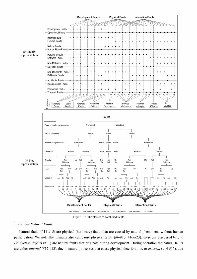
If all combinations of the eight elementary fault classes were possible, there would be 256 different combined
fault classes. However, not all criteria are applicable to all fault classes; for example, natural faults cannot be
classified by objective, intent, and capability. We have identified 31 likely combinations; they are shown in Figure
3.3.
More combinations may be identified in the future. The combined fault classes of Figure 3.3 are shown to
belong to three major partially overlapping groupings:
• development faults that include all fault classes occurring during development;
• physical faults that include all fault classes that affect hardware;
• interaction faults that include all external faults.
The boxes at the bottom of Figure 3.3.a identify the names of some illustrative fault classes.
Knowledge of all possible fault classes allows the user to decide which classes should be included in a
dependability & security specification. Next we comment on the fault classes that are shown in Figure 3.3. Fault
numbers (#1 to #31) will be used to relate the discussion to Figure 3.3.
9
(a) Matrix representation
Physical Faults Interaction FaultsDevelopment Faults
Logic Bombs
SoftwareFlaws
HardwareErrata
PhysicalInterference
ProductionDefects
InputMistakes
PhysicalDeterioration
Viruses& Worms
Exam
ples
1 2 3 4 5 6 7 8 9 10 11 12 13 14 15 16 17 18 19 20 21 22 23 24 25 26 27 28 29 30
Non-Deliberate FaultsDeliberate Faults � �
� ��
�
� � �
��
�
�
� � � �
�
�
� �
�
��
�
� � �
Operational FaultsDevelopment Faults
� � � �
�
� � �
��� �
� � � � �� � � � �
� ��� � �
External FaultsInternal Faults
�
� � ���� �
� � � �� � � ���� � � �
��� � � �
Natural FaultsHuman-Made Faults
�
� � ��
� � �
�
�
�� � � � � � �� ��� � � �� � �
Software FaultsHardware Faults � � � �
�
� � � �
��� �
� � � � �� � � �
� � �� � �
Malicious FaultsNon-Malicious Faults � � � ��
�
� � �
�
�� � � � � �� � �
� �
� � �� � �
Incompetence FaultsAccidental Faults �
�
�
�
�
�
�
�
� �� � � �
�
�
� �
�
� �
�
� �
Permanent FaultsTransient Faults
� � ���� � ��� � �
�
�
� � � �
�
�
�
�
�
�
�
�
�
�
�
�
�
�
�
�
�
�
�
�� �
�
�
�
�
�
�
�
�
�
�
31
IntrusionAttempts
(b) Tree representation
Faults
Phase of creation or occurrence
System boundaries
Phenomenological cause
Dimension
Objective
Intent
Capability
Persistence Per Per Per Per Per Per Per Per Per Per Per Per Tr Per Tr Tr Tr Tr Per Tr Per Tr PerTr PerTr Tr Tr Per Tr
Acc Inc Acc Inc Acc Inc
1 2 3 4 5 6 7 8 9 10 11 12 13 14 15 16 17 18 19 20 21 22 23 24 25 26 27 28 29 30
Acc Inc Acc Acc Acc Acc Inc Acc Inc Acc Inc Acc Inc
NonDel
Del Del Del NonDel
Del NonDel
NonDel
NonDel
NonDel
Del Del Del DelNonDel
NonMalicious
NonMalicious
Mal Mal
Software Hardware
NonMal
NonMal
NonMal
NonMalicious
NonMalicious
Mal Mal
Hardw Hardw Hardw Hardware Software
Human-made Human-madeNatural Natural Natural
Internal Internal External
Development Operational
Development Faults Physical Faults Interaction Faults
Per
31
Mal: Malicious Del: Deliberate Acc: Accidental Inc: Incompetence Per: Permanent Tr: Transient Figure 3.3: The classes of combined faults
3.2.2. On Natural Faults
Natural faults (#11-#15) are physical (hardware) faults that are caused by natural phenomena without human
participation. We note that humans also can cause physical faults (#6-#10, #16-#23); these are discussed below.
Production defects (#11) are natural faults that originate during development. During operation the natural faults
are either internal (#12-#13), due to natural processes that cause physical deterioration, or external (#14-#15), due
10
to natural processes that originate outside the system boundaries and cause physical interference by penetrating the
hardware boundary of the system (radiation, etc.) or by entering via use interfaces (power transients, noisy input
lines, etc.).
3.2.3. On Human-Made Faults
The definition of human-made faults (that result from human actions) includes absence of actions when actions
should be performed, i.e., omission faults, or simply omissions. Performing wrong actions leads to commission
faults.
The two basic classes of human-made faults are distinguished by the objective of the developer or of the
humans interacting with the system during its use:
• malicious faults, introduced during either system development with the objective to cause harm to the system
during its use (#5-#6), or directly during use (#22-#25)
• non-malicious faults (#1-#4, #7-#21, #26-#31), introduced without malicious objectives.
We consider non-malicious faults first. They can be partitioned according to the developer’s intent:
• non-deliberate faults that are due to mistakes, that is, unintended actions of which the developer, operator,
maintainer, etc. is not aware (#1, #2, #7, #8, #16-#18, #26-#28);
• deliberate faults that are due to bad decisions, that is, intended actions that are wrong and cause faults (#3, #4,
#9, #10, #19-#21, #29-#31).
Deliberate, non-malicious, development faults (#3, #4, #9, #10) result generally from tradeoffs, either a) aimed
at preserving acceptable performance, at facilitating system utilization, or b) induced by economic considerations.
Deliberate, non-malicious interaction faults (#19-#21, #29-#31) may result from the action of an operator either
aimed at overcoming an unforeseen situation, or deliberately violating an operating procedure without having
realized the possibly damaging consequences of this action. Deliberate non-malicious faults are often recognized
as faults only after an unacceptable system behavior, thus a failure, has ensued; the developer(s) or operator(s) did
not realize at the time that the consequence of their decision was a fault.
It is usually considered that both mistakes and bad decisions are accidental, as long as they are not made with
malicious objectives. However, not all mistakes and bad decisions by non-malicious persons are accidents. Some
very harmful mistakes and very bad decisions are made by persons who lack professional competence to do the job
they have undertaken. A complete fault taxonomy should not conceal this cause of faults, therefore we introduce a
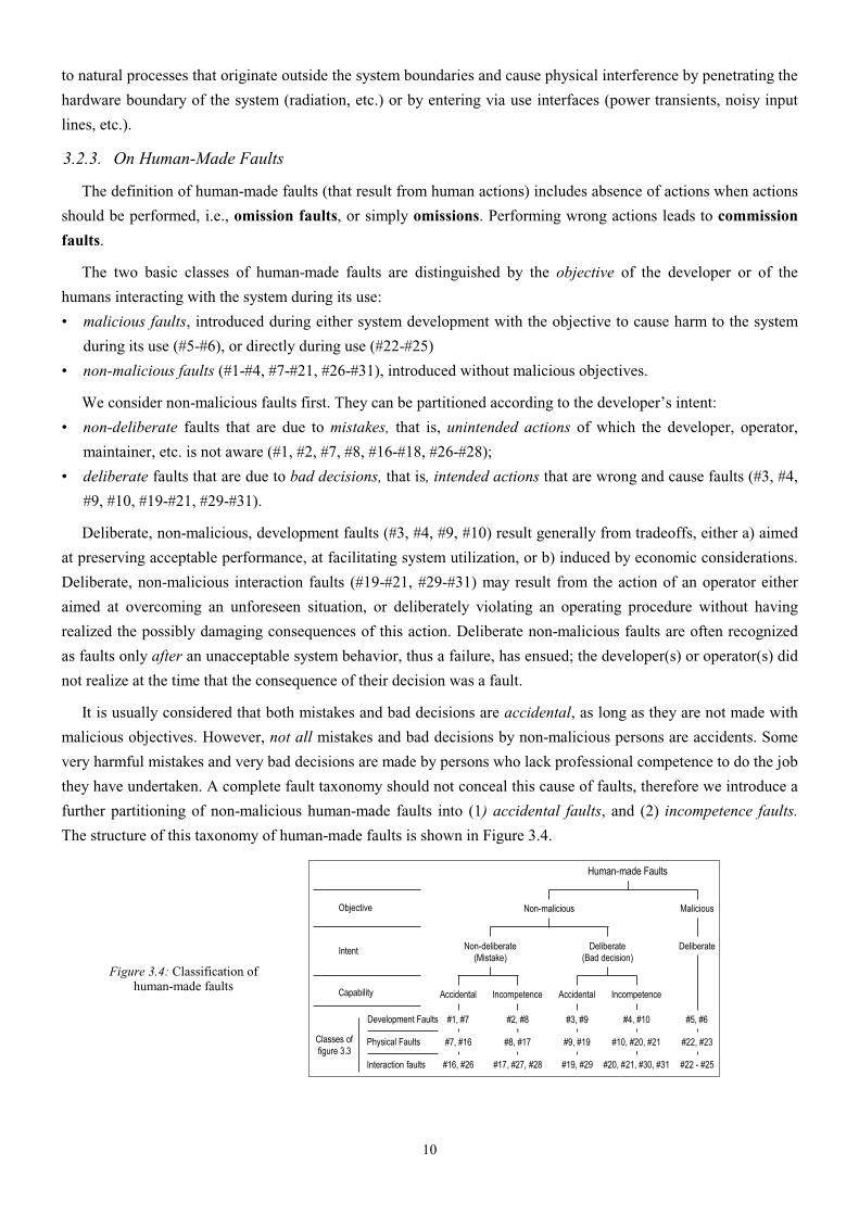
further partitioning of non-malicious human-made faults into (1) accidental faults, and (2) incompetence faults.
The structure of this taxonomy of human-made faults is shown in Figure 3.4.
Figure 3.4: Classification of human-made faults
Human-made Faults
Non-malicious MaliciousObjective
Classes of figure 3.3
Intent Non-deliberate(Mistake)
Deliberate(Bad decision)
Deliberate
Accidental Incompetence Accidental IncompetenceCapability
#7, #16 #8, #17 #9, #19 #10, #20, #21 #22, #23Physical Faults
Interaction faults #16, #26 #17, #27, #28 #19, #29 #20, #21, #30, #31 #22 - #25
#1, #7 #2, #8 #3, #9 #4, #10 #5, #6Development Faults
11
The question of how to recognize incompetence faults becomes important when a mistake or a bad decision has
consequences that lead to economic losses, injuries, or loss of human lives. In such cases independent professional
judgment by a board of inquiry or legal proceedings in a court of law are likely to be needed to decide if
professional malpractice was involved.
Thus far the discussion of incompetence faults has dealt with individuals. However, human-made efforts have
failed because a team or an entire organization did not have the organizational competence to do the job. A good
example of organizational incompetence is the development failure of the AAS system, that was intended to
replace the aging air traffic control systems in the USA [US DOT 1998].
Non-malicious development faults can exist in hardware and in software. In hardware, especially in
microprocessors, some development faults are discovered after production has started [Avizienis & He 1999].
Such faults are called “errata” and are listed in specification updates. The finding of errata typically continues
throughout the life of the processors, therefore new specification updates are issued periodically. Some
development faults are introduced because human-made tools are faulty.
Off-the-shelf (OTS) components are inevitably used in system design. The use of OTS components introduces
additional problems. They may come with known development faults, and may contain unknown faults as well
(bugs, vulnerabilities, undiscovered errata, etc.). Their specifications may be incomplete or even incorrect. This
problem is especially serious when legacy OTS components are used that come from previously designed and used
systems, and must be retained in the new system because of the user’s needs.
Some development faults affecting software can cause software aging [Huang et al. 1995], i.e., progressively
accrued error conditions resulting in performance degradation or complete failure. Examples are [Castelli et al.
2001] memory bloating and leaking, unterminated threads, unreleased file-locks, data corruption, storage space
fragmentation, accumulation of round-off errors.
3.2.4. On Malicious Faults
Malicious human-made faults are introduced with the malicious objective to alter the functioning of the system
during use. Because of the objective, classification according to intent and capability is not applicable. The goals
of such faults are: (1) to disrupt or halt service, causing denials of service, (2) to access confidential information,
or (3) to improperly modify the system. They are grouped into two classes:
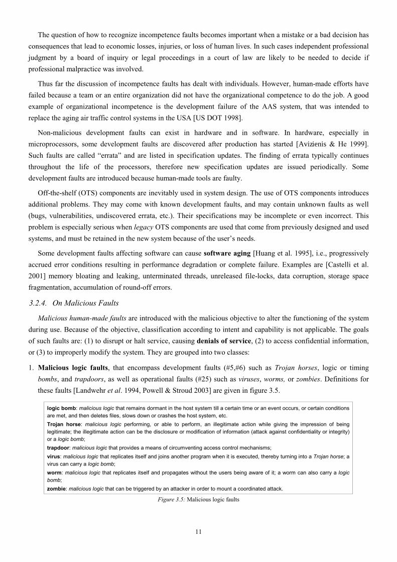
1. Malicious logic faults, that encompass development faults (#5,#6) such as Trojan horses, logic or timing
bombs, and trapdoors, as well as operational faults (#25) such as viruses, worms, or zombies. Definitions for
these faults [Landwehr et al. 1994, Powell & Stroud 2003] are given in figure 3.5.
logic bomb: malicious logic that remains dormant in the host system till a certain time or an event occurs, or certain conditions are met, and then deletes files, slows down or crashes the host system, etc.
Trojan horse: malicious logic performing, or able to perform, an illegitimate action while giving the impression of being legitimate; the illegitimate action can be the disclosure or modification of information (attack against confidentiality or integrity) or a logic bomb;
trapdoor: malicious logic that provides a means of circumventing access control mechanisms;
virus: malicious logic that replicates itself and joins another program when it is executed, thereby turning into a Trojan horse; a virus can carry a logic bomb;
worm: malicious logic that replicates itself and propagates without the users being aware of it; a worm can also carry a logic bomb;
zombie: malicious logic that can be triggered by an attacker in order to mount a coordinated attack.
Figure 3.5: Malicious logic faults

12
2. Intrusion attempts, that are operational external faults (#22-#24). The external character of intrusion attempts
does not exclude the possibility that they may be performed by system operators or administrators who are
exceeding their rights, and intrusion attempts may use physical means to cause faults: power fluctuation,
radiation, wire-tapping, heating/cooling, etc.
What is colloquially known as an “exploit” is in essence a software script that will exercise a system
vulnerability and allow an intruder to gain access to, and sometimes control of, a system. In the terms defined here,
invoking the exploit is an operational, external, human-made, software, malicious interaction fault (#24-#25).
Heating the RAM with a hairdryer to cause memory errors that permit software security violations would be an
external, human-made, hardware, malicious interaction fault (#22-#23). The vulnerability that an exploit takes
advantage of is typically a software flaw (e.g. an unchecked buffer) that could be characterized as a
developmental, internal, human-made, software, non-malicious, non-deliberate, permanent fault (#1-#2).
3.2.5. On interaction faults
Interaction faults occur during the use phase, therefore they are all operational faults. They are caused by
elements of the use environment (see Section 3.1) interacting with the system, therefore they are all external. Most
classes originate due to some human action in the use environment, therefore they are human-made. They are fault
classes #16-#31 in Figure 3.3. An exception are external natural faults (#14-#15) caused by cosmic rays, solar
flares, etc. Here nature interacts with the system without human participation
A broad class of human-made operational faults are configuration faults, i.e., wrong setting of parameters that
can affect security, networking, storage, middleware, etc. [Gray 2001]. Such faults can occur during configuration
changes performed during adaptive or augmentative maintenance performed concurrently with system operation
(e.g., introduction of a new software version on a network server); they are then called reconfiguration faults
[Wood 1994].
As mentioned in section 2.2, a common feature of interaction faults is that, in order to be ‘successful’, they
usually necessitate the prior presence of a vulnerability, i.e. an internal fault that enables an external fault to harm
the system. Vulnerabilities can be development or operational faults; they can be malicious or non-malicious, as
can be the external faults that exploit them. There are interesting and obvious similarities between an intrusion
attempt and a physical external fault that ‘exploits’ a lack of shielding. A vulnerability can result from a deliberate
development fault, for economic or for usability reasons, thus resulting in limited protections, or even in their
absence.
3.3. Failures
3.3.1. Service Failures
In Section 2.2 a service failure is defined as an event that occurs when the delivered service deviates from
correct service. The different ways in which the deviation is manifested are a system’s service failure modes. Each
mode can have more than one service failure severity.
The occurrence of a failure was defined in Section 2 with respect to the function of a system, not with respect
to the description of the function stated in the functional specification: a service delivery complying with the
specification may be unacceptable for the system user(s), thus uncovering a specification fault, i.e., revealing the
fact that the specification did not adequately describe the system function(s). Such specification faults can be
either omission or commission faults (misinterpretations, unwarranted assumptions, inconsistencies, typographical

13
mistakes). In such circumstances, the fact that the event is undesired (and is in fact a failure) may be recognized
only after its occurrence, for instance via its consequences. So failures can be subjective and disputable, i.e., may
require judgment to identify and characterize.
The service failure modes characterize incorrect service according to four viewpoints: a) the failure domain,
b) the detectability of failures, c) the consistency of failures, and d) the consequences of failures on the
environment.
The failure domain viewpoint leads us to distinguish:
• content failures: the content of the information delivered at the service interface (i.e., the service content)
deviates from implementing the system function;
• timing failures: the time of arrival or the duration of the information delivered at the service interface (i.e., the
timing of service delivery) deviates from implementing the system function.
These definitions can be specialized: a) the content can be in numerical or non-numerical sets (e.g., alphabets,
graphics, colors, sounds), and b) a timing failure may be early or late, depending on whether the service is
delivered too early or too late. Failures when both information and timing are incorrect fall into two classes:
• halt failure, or simply halt, when the service is halted (the external state becomes constant, i.e., system
activity, if there is any, is no longer perceptible to the users); a special case of halt is silent failure, or simply
silence, when no service at all is delivered at the service interface (e.g., no messages are sent in a distributed
system);
• erratic failures otherwise, i.e., when a service is delivered (not halted), but is erratic (e.g., babbling).
Figure 3.6 summarizes the service failure modes with respect to the failure domain viewpoint.
Figure 3.6: Service failure modes with respect to the failure domain
viewpoint
Failure Domain
Content(Correct timing)
Timing(Correctcontent)
Content and Timing
ContentFailure
Early TimingFailure
PerformanceFailure
HaltFailure
ErraticFailure
Earlyservice
Lateservice
Haltedservice
Erraticservice
The detectability viewpoint addresses the signaling of service failures to the user(s). Signaling at the service
interface originates from detecting mechanisms in the system that check the correctness of the delivered service.
When the losses are detected and signaled by a warning signal, then signaled failures occur. Otherwise, they are
unsignaled failures. The detecting mechanisms themselves have two failure modes: a) signaling a loss of function
when no failure has actually occurred, that is a false alarm, b) not signaling a function loss, that is an unsignaled
failure. When the occurrence of service failures result in reduced modes of service, the system signals a degraded
mode of service to the user(s). Degraded modes may range from minor reductions to emergency service and safe
shutdown.
The consistency of failures leads us to distinguish, when a system has two or more users:
• consistent failures: the incorrect service is perceived identically by all system users;

14
• inconsistent failures: some or all system users perceive differently incorrect service (some users may actually
perceive correct service); inconsistent failures are usually called, after [Lamport et al. 1982], Byzantine
failures.
Grading the consequences of the failures upon the system environment enables failure severities to be defined.
The failure modes are ordered into severity levels, to which are generally associated maximum acceptable
probabilities of occurrence. The number, the labeling and the definition of the severity levels, as well as the
acceptable probabilities of occurrence, are application-related, and involve the dependability & security attributes
for the considered application(s). Examples of criteria for determining the classes of failure severities are a) for
availability, the outage duration, b) for safety, the possibility of human lives being endangered, c) for
confidentiality, the type of information that may be unduly disclosed, and d) for integrity, the extent of the
corruption of data and the ability to recover from these corruptions.
Generally speaking, two limiting levels can be defined according to the relation between the benefit (in the
broad sense of the term, not limited to economic considerations) provided by the service delivered in the absence
of failure, and the consequences of failures:
• minor failures, where the harmful consequences are of similar cost to the benefits provided by correct service
delivery;
• catastrophic failures, where the cost of harmful consequences is orders of magnitude, or even
incommensurably, higher than the benefit provided by correct service delivery.
Figure 3.7 summarizes the service failure modes.
Figure 3.7: Service failure modes
FailuresDetectability Signaled failures
Unsignaled failures
ConsistencyConsistent failures Inconsistent failures
Consequences
Minor failures
Catastrophic failures
•••
Domain
Content failuresEarly timing failuresLate timing failuresHalt failuresErratic failures
Systems that are designed and implemented so that they fail only in specific modes of failure described in the
dependability & security specification and only to an acceptable extent, are fail-controlled systems, e.g., with
stuck output as opposed to delivering erratic values, silence as opposed to babbling, consistent as opposed to
inconsistent failures. A system whose failures are to an acceptable extent halting failures only, is a fail-halt (or
fail-stop) system; the situations of stuck service and of silence lead respectively to fail-passive systems and fail-
silent systems [Powell et al. 1988]. A system whose failures are, to an acceptable extent, all minor ones is a fail-
safe system.
As defined in Section 2, delivery of incorrect service is an outage, which lasts until service restoration. The
outage duration may vary significantly, depending on the actions involved in service restoration after a failure has
occurred: a) automatic or operator-assisted recovery, restart or reboot, b) corrective maintenance. Correction of
development faults (by patches or workarounds) is usually performed off-line, after service restoration, and the
upgraded components resulting from fault correction are then introduced at some appropriate time, with or without

15
interruption of system operation. Preemptive interruption of system operation for an upgrade or for preventive
maintenance is a service shutdown, also called a planned outage (as opposed to an outage consecutive to failure,
which is then called an unplanned outage).
3.3.2. Development Failures
As stated in section 3.1, development faults may be introduced into the system being developed by its
environment, especially by human developers, development tools, and production facilities. Such development
faults may contribute to partial or complete development failures, or they may remain undetected until the use
phase. A complete development failure causes the development process to be terminated before the system is
accepted for use and placed into service. There are two aspects of development failures:
1. Budget failure: the allocated funds are exhausted before the system passes acceptance testing.
2. Schedule failure: the projected delivery schedule slips to a point in the future where the system would be
technologically obsolete or functionally inadequate for the user’s needs.
The principal causes of development failures are: incomplete or faulty specifications, an excessive number of
user-initiated specification changes; inadequate design with respect to functionality and/or performance goals; too
many development faults; inadequate fault removal capability; prediction of insufficient dependability or security;
faulty estimates of development costs. All are usually due to an underestimate of the complexity of the system to
be developed.
There are two kinds of partial development failures, i.e., failures of lesser severity than project termination.
Budget or schedule overruns occur when the development is completed, but the funds or time needed to complete
the effort exceed the original estimates. Another form of partial development failure is downgrading: the
developed system is delivered with less functionality, lower performance, or is predicted to have lower
dependability or security, than was required in the original system specification.
Development failures, overruns, and downgrades have a very negative impact on the user community: see, e.g.,
statistics about large software projects [Johnson 1995], or the analysis of the complete development failure of the
AAS system, that resulted in the waste of $1.5 billion [US DOT 1998].
3.3.3. Dependability & Security Failures
It is to be expected that faults of various kinds will affect the system during its use phase. The faults may cause
unacceptably degraded performance or total failure to deliver the specified service. For this reason a dependability
& security specification is agreed upon that states the goals for each attribute: availability, reliability, safety,
confidentiality, integrity, and maintainability.
The specification explicitly identifies the classes of faults that are expected and the use environment in which
the system will operate. The specification may also require safeguards against certain undesirable or dangerous
conditions. Furthermore, the inclusion of specific fault prevention or fault tolerance techniques may be required by
the user.
A dependability or security failure occurs when the given system suffers service failures more frequently or
more severely than acceptable.
The dependability & security specification can also contain faults. Omission faults can occur in description of
the use environment or in choice of the classes of faults to be prevented or tolerated. Another class of faults is the
unjustified choice of very high requirements for one or more attributes that raises the cost of development and may

16
lead to a cost overrun or even a development failure. For example, the initial AAS complete outage limit of 3
seconds per year was changed to 5 minutes per year for the new contract in 1994 [US DOT 1998].
3.4. Errors
An error has been defined in Section 2.2 as the part of a system’s total state that may lead to a failure — a
failure occurs when the error causes the delivered service to deviate from correct service. The cause of the error
has been called a fault.
An error is detected if its presence is indicated by an error message or error signal. Errors that are present but
not detected are latent errors.
Since a system consists of a set of interacting components, the total state is the set of its component states. The
definition implies that a fault originally causes an error within the state of one (or more) components, but service
failure will not occur as long as the external state of that component is not part of the external state of the system.
Whenever the error becomes a part of the external state of the component, a service failure of that component
occurs, but the error remains internal to the entire system.
Whether or not an error will actually lead to a service failure depends on two factors:
1. The structure of the system, and especially the nature of any redundancy that exists in it:
• protective redundancy, introduced to provide fault tolerance, that is explicitly intended to prevent an
error from leading to service failure;
• unintentional redundancy (it is in practice difficult if not impossible to build a system without any form
of redundancy) that may have the same — presumably unexpected — result as intentional redundancy.
2. The behavior of the system: the part of the state that contains an error may never be needed for service, or an
error may be eliminated (e.g., when overwritten) before it leads to a failure.
A convenient classification of errors is to describe them in terms of the elementary service failures that they
cause, using the terminology of Section 3.3.1: content vs. timing errors, detected vs. latent errors, consistent vs.
inconsistent errors when the service goes to two or more users, minor vs. catastrophic errors. In the field of error
control codes, content errors are further classified according to the damage pattern: single, double, triple, byte,
burst, erasure, arithmetic, track, etc., errors.
Some faults (e.g., a burst of electromagnetic radiation) can simultaneously cause errors in more than one
component. Such errors are called multiple related errors. Single errors are errors that affect one component
only.
3.5. The Pathology of Failure: Relationship between Faults, Errors and Failures
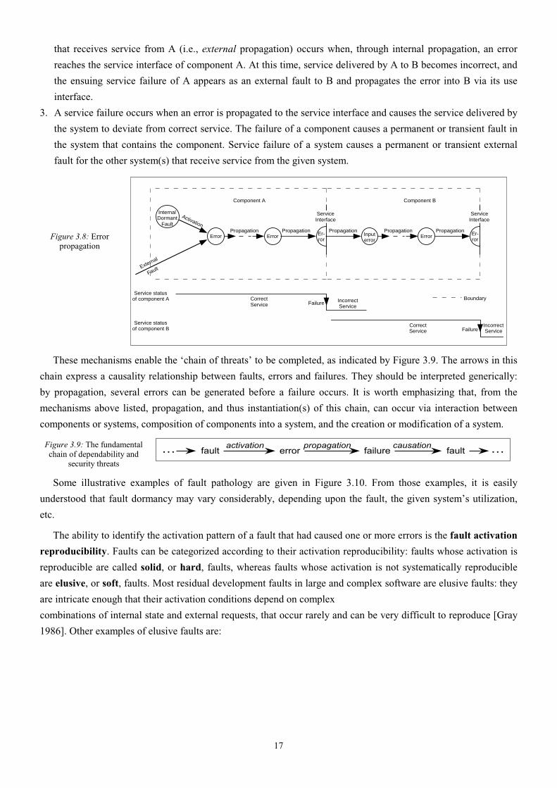
The creation and manifestation mechanisms of faults, errors, and failures are illustrated by Figure 3.8, and
summarized as follows:
1. A fault is active when it produces an error, otherwise it is dormant. An active fault is either a) an internal fault
that was previously dormant and that has been activated by the computation process or environmental
conditions, or b) an external fault. Fault activation is the application of an input (the activation pattern) to a
component that causes a dormant fault to become active. Most internal faults cycle between their dormant and
active states.
2. Error propagation within a given component (i.e., internal propagation) is caused by the computation process:
an error is successively transformed into other errors. Error propagation from component A to component B
17
that receives service from A (i.e., external propagation) occurs when, through internal propagation, an error
reaches the service interface of component A. At this time, service delivered by A to B becomes incorrect, and
the ensuing service failure of A appears as an external fault to B and propagates the error into B via its use
interface.
3. A service failure occurs when an error is propagated to the service interface and causes the service delivered by
the system to deviate from correct service. The failure of a component causes a permanent or transient fault in
the system that contains the component. Service failure of a system causes a permanent or transient external
fault for the other system(s) that receive service from the given system.
Figure 3.8: Error propagation
InternalDormant
Fault
Activation
CorrectService
IncorrectService
Failure
External
Fault
Propagation
Component A Component B
Service statusof component A
Propagation
CorrectService
IncorrectService
Service statusof component B
Er-ror
Er-ror
Propagation PropagationError Error Input
errorError
Failure
ServiceInterface
Propagation
ServiceInterface
Boundary
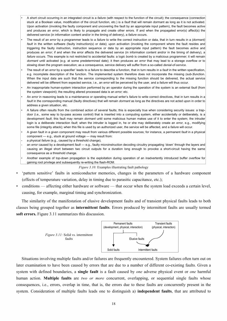
These mechanisms enable the ‘chain of threats’ to be completed, as indicated by Figure 3.9. The arrows in this
chain express a causality relationship between faults, errors and failures. They should be interpreted generically:
by propagation, several errors can be generated before a failure occurs. It is worth emphasizing that, from the
mechanisms above listed, propagation, and thus instantiation(s) of this chain, can occur via interaction between
components or systems, composition of components into a system, and the creation or modification of a system.
Figure 3.9: The fundamental chain of dependability and
security threats
errorfault failure faultactivation propagation causation ……
Some illustrative examples of fault pathology are given in Figure 3.10. From those examples, it is easily
understood that fault dormancy may vary considerably, depending upon the fault, the given system’s utilization,
etc.
The ability to identify the activation pattern of a fault that had caused one or more errors is the fault activation
reproducibility. Faults can be categorized according to their activation reproducibility: faults whose activation is
reproducible are called solid, or hard, faults, whereas faults whose activation is not systematically reproducible
are elusive, or soft, faults. Most residual development faults in large and complex software are elusive faults: they
are intricate enough that their activation conditions depend on complex
combinations of internal state and external requests, that occur rarely and can be very difficult to reproduce [Gray
1986]. Other examples of elusive faults are:
18
• A short circuit occurring in an integrated circuit is a failure (with respect to the function of the circuit); the consequence (connection stuck at a Boolean value, modification of the circuit function, etc.) is a fault that will remain dormant as long as it is not activated. Upon activation (invoking the faulty component and uncovering the fault by an appropriate input pattern), the fault becomes active and produces an error, which is likely to propagate and create other errors. If and when the propagated error(s) affect(s) the delivered service (in information content and/or in the timing of delivery), a failure occurs.
• The result of an error by a programmer leads to a failure to write the correct instruction or data, that in turn results in a (dormant) fault in the written software (faulty instruction(s) or data); upon activation (invoking the component where the fault resides and triggering the faulty instruction, instruction sequence or data by an appropriate input pattern) the fault becomes active and produces an error; if and when the error affects the delivered service (in information content and/or in the timing of delivery), a failure occurs. This example is not restricted to accidental faults: a logic bomb is created by a malicious programmer; it will remain dormant until activated (e.g. at some predetermined date); it then produces an error that may lead to a storage overflow or to slowing down the program execution; as a consequence, service delivery will suffer from a so-called denial-of-service.
• The result of an error by a specifier’ leads to a failure to describe a function, that in turn results in a fault in the written specification, e.g. incomplete description of the function. The implemented system therefore does not incorporate the missing (sub-)function. When the input data are such that the service corresponding to the missing function should be delivered, the actual service delivered will be different from expected service, i.e., an error will be perceived by the user, and a failure will thus occur.
• An inappropriate human-system interaction performed by an operator during the operation of the system is an external fault (from the system viewpoint); the resulting altered processed data is an error; etc.
• An error in reasoning leads to a maintenance or operating manual writer’s failure to write correct directives, that in turn results in a fault in the corresponding manual (faulty directives) that will remain dormant as long as the directives are not acted upon in order to address a given situation, etc.
• A failure often results from the combined action of several faults; this is especially true when considering security issues: a trap-door (i.e., some way to by-pass access control) that is inserted into a computing system, either accidentally or deliberately, is a development fault; this fault may remain dormant until some malicious human makes use of it to enter the system; the intruder login is a deliberate interaction fault; when the intruder is logged in, he or she may deliberately create an error, e.g., modifying some file (integrity attack); when this file is used by an authorized user, the service will be affected, and a failure will occur.
• A given fault in a given component may result from various different possible sources; for instance, a permanent fault in a physical component — e.g., stuck at ground voltage — may result from:
- a physical failure (e.g., caused by a threshold change), - an error caused by a development fault — e.g., faulty microinstruction decoding circuitry propagating ‘down’ through the layers and
causing an illegal short between two circuit outputs for a duration long enough to provoke a short-circuit having the same consequence as a threshold change.
• Another example of top-down propagation is the exploitation during operation of an inadvertently introduced buffer overflow for gaining root privilege and subsequently re-writing the flash-ROM.
Figure 3.10: Examples illustrating fault pathology
• ‘pattern sensitive’ faults in semiconductor memories, changes in the parameters of a hardware component
(effects of temperature variation, delay in timing due to parasitic capacitance, etc.);
• conditions — affecting either hardware or software — that occur when the system load exceeds a certain level,
causing, for example, marginal timing and synchronization.
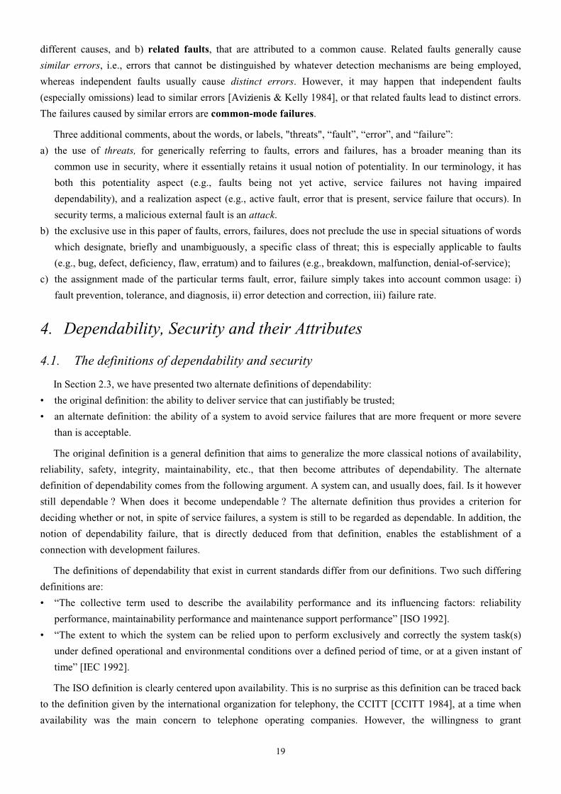
The similarity of the manifestation of elusive development faults and of transient physical faults leads to both
classes being grouped together as intermittent faults. Errors produced by intermittent faults are usually termed
soft errors. Figure 3.11 summarizes this discussion.
Figure 3.11: Solid vs. intermittent faults
Permanent faults(development, physical, interaction)
Transient faults(physical, interaction)
Elusive faults
Solid faults Intermittent faults
Situations involving multiple faults and/or failures are frequently encountered. System failures often turn out on
later examination to have been caused by errors that are due to a number of different co-existing faults. Given a
system with defined boundaries, a single fault is a fault caused by one adverse physical event or one harmful
human action. Multiple faults are two or more concurrent, overlapping, or sequential single faults whose
consequences, i.e., errors, overlap in time, that is, the errors due to these faults are concurrently present in the
system. Consideration of multiple faults leads one to distinguish a) independent faults, that are attributed to
19
different causes, and b) related faults, that are attributed to a common cause. Related faults generally cause
similar errors, i.e., errors that cannot be distinguished by whatever detection mechanisms are being employed,
whereas independent faults usually cause distinct errors. However, it may happen that independent faults
(especially omissions) lead to similar errors [Avizienis & Kelly 1984], or that related faults lead to distinct errors.
The failures caused by similar errors are common-mode failures.
Three additional comments, about the words, or labels, "threats", “fault”, “error”, and “failure”:
a) the use of threats, for generically referring to faults, errors and failures, has a broader meaning than its
common use in security, where it essentially retains it usual notion of potentiality. In our terminology, it has
both this potentiality aspect (e.g., faults being not yet active, service failures not having impaired
dependability), and a realization aspect (e.g., active fault, error that is present, service failure that occurs). In
security terms, a malicious external fault is an attack.
b) the exclusive use in this paper of faults, errors, failures, does not preclude the use in special situations of words
which designate, briefly and unambiguously, a specific class of threat; this is especially applicable to faults
(e.g., bug, defect, deficiency, flaw, erratum) and to failures (e.g., breakdown, malfunction, denial-of-service);
c) the assignment made of the particular terms fault, error, failure simply takes into account common usage: i)
fault prevention, tolerance, and diagnosis, ii) error detection and correction, iii) failure rate.
4. Dependability, Security and their Attributes
4.1. The definitions of dependability and security
In Section 2.3, we have presented two alternate definitions of dependability:
• the original definition: the ability to deliver service that can justifiably be trusted;
• an alternate definition: the ability of a system to avoid service failures that are more frequent or more severe
than is acceptable.
The original definition is a general definition that aims to generalize the more classical notions of availability,
reliability, safety, integrity, maintainability, etc., that then become attributes of dependability. The alternate
definition of dependability comes from the following argument. A system can, and usually does, fail. Is it however
still dependable ? When does it become undependable ? The alternate definition thus provides a criterion for
deciding whether or not, in spite of service failures, a system is still to be regarded as dependable. In addition, the
notion of dependability failure, that is directly deduced from that definition, enables the establishment of a
connection with development failures.
The definitions of dependability that exist in current standards differ from our definitions. Two such differing
definitions are:
• “The collective term used to describe the availability performance and its influencing factors: reliability
performance, maintainability performance and maintenance support performance” [ISO 1992].
• “The extent to which the system can be relied upon to perform exclusively and correctly the system task(s)
under defined operational and environmental conditions over a defined period of time, or at a given instant of
time” [IEC 1992].
The ISO definition is clearly centered upon availability. This is no surprise as this definition can be traced back
to the definition given by the international organization for telephony, the CCITT [CCITT 1984], at a time when
availability was the main concern to telephone operating companies. However, the willingness to grant
20
dependability a generic character is noteworthy, since it goes beyond availability as it was usually defined, and
relates it to reliability and maintainability. In this respect, the ISO/CCITT definition is consistent with the
definition given in [Hosford 1960] for dependability: “the probability that a system will operate when needed”.
The second definition, from [IEC 1992], introduces the notion of reliance, and as such is much closer to our
definitions.
Terminology in the security world has its own rich history. Computer security, communications security,
information security, and information assurance are terms that have had a long development and use in the
community of security researchers and practitioners, mostly without direct reference to dependability.
Nevertheless, all of these terms can be understood in terms of the three primary security attributes of
confidentiality, integrity, and availability.
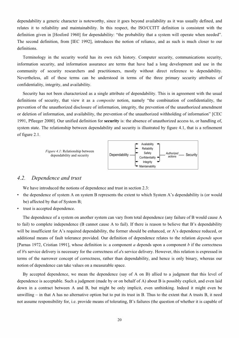
Security has not been characterized as a single attribute of dependability. This is in agreement with the usual
definitions of security, that view it as a composite notion, namely “the combination of confidentiality, the
prevention of the unauthorized disclosure of information, integrity, the prevention of the unauthorized amendment
or deletion of information, and availability, the prevention of the unauthorized withholding of information” [CEC
1991, Pfleeger 2000]. Our unified definition for security is: the absence of unauthorized access to, or handling of,
system state. The relationship between dependability and security is illustrated by figure 4.1, that is a refinement
of figure 2.1.
Figure 4.1: Relationship between dependability and security SecurityDependability
AvailabilityReliability
Safety
ConfidentialityIntegrity
Maintainability
Authorizedactions
4.2. Dependence and trust
We have introduced the notions of dependence and trust in section 2.3:
• the dependence of system A on system B represents the extent to which System A’s dependability is (or would
be) affected by that of System B;
• trust is accepted dependence.
The dependence of a system on another system can vary from total dependence (any failure of B would cause A
to fail) to complete independence (B cannot cause A to fail). If there is reason to believe that B’s dependability
will be insufficient for A’s required dependability, the former should be enhanced, or A’s dependence reduced, or
additional means of fault tolerance provided. Our definition of dependence relates to the relation depends upon
[Parnas 1972, Cristian 1991], whose definition is: a component a depends upon a component b if the correctness
of b's service delivery is necessary for the correctness of a's service delivery. However, this relation is expressed in
terms of the narrower concept of correctness, rather than dependability, and hence is only binary, whereas our
notion of dependence can take values on a measurable space.
By accepted dependence, we mean the dependence (say of A on B) allied to a judgment that this level of
dependence is acceptable. Such a judgment (made by or on behalf of A) about B is possibly explicit, and even laid
down in a contract between A and B, but might be only implicit, even unthinking. Indeed it might even be
unwilling – in that A has no alternative option but to put its trust in B. Thus to the extent that A trusts B, it need
not assume responsibility for, i.e. provide means of tolerating, B’s failures (the question of whether it is capable of
21
doing this is another matter). In fact the extent to which A fails to provide means of tolerating B’s failures is a
measure of A’s (perhaps unthinking or unwilling) trust in B.
4.3. The attributes of dependability and security
The attributes of dependability and security that have been defined in Section 2.3 may be of varying importance
depending on the application intended for the given computing system: availability, integrity and maintainability
are generally required, although to a varying degree depending on the application, whereas reliability, safety, and
confidentiality may or may not be required according to the application. The extent to which a system possesses
the attributes of dependability and security should be considered in a relative, probabilistic, sense, and not in an
absolute, deterministic sense: due to the unavoidable presence or occurrence of faults, systems are never totally
available, reliable, safe, or secure.
The definition given for integrity — absence of improper system state alterations — goes beyond the usual
definitions, that a) relate to the notion of authorized actions only, and, b) focus on information (e.g., prevention of
the unauthorized amendment or deletion of information [CEC 1991], assurance of approved data alterations [Jacob
1991]): a) naturally, when a system implements an authorization policy, ‘improper’ encompasses ‘unauthorized’,
b) ‘improper alterations’ encompass actions that prevent (correct) upgrades of information, and c) ‘system state’
includes system modifications or damages.
The definition given for maintainability intentionally goes beyond corrective and preventive maintenance, and
encompasses the other forms of maintenance defined in section 3, i.e., adaptive and augmentative maintenance.
The concept of autonomic computing [Ganek & Korbi 2003] has as its major aim the provision of high
maintainability for large networked computer systems, though automation of their management.
Besides the attributes defined in Section 2, and discussed above, other, secondary, attributes can be defined,
which refine or specialize the primary attributes as defined in Section 2. An example of a specialized secondary
attribute is robustness, i.e., dependability with respect to external faults, which characterizes a system reaction to
a specific class of faults.
The notion of secondary attributes is especially relevant for security, and is based on distinguishing among
various types of information [Cachin et al. 2000]. Examples of such secondary attributes are:
• accountability: availability and integrity of the identity of the person who performed an operation;
• authenticity: integrity of a message content and origin, and possibly of some other information, such as the
time of emission;
• non-repudiability: availability and integrity of the identity of the sender of a message (non-repudiation of the
origin), or of the receiver (non-repudiation of reception).
The concept of a security policy is that of a set of security-motivated constraints, that are to be adhered to by,
for example, an organization or a computer system [NIST 1995]. The enforcement of such constraints may be via
technical, management and/or operational controls, and the policy may lay down how these controls are to be
enforced. In effect therefore a security policy is a (partial) system specification, lack of adherence to which will be
regarded as a security failure. In practice there may be a hierarchy of such security policies, relating to a hierarchy
of systems - for example, an entire company, its information systems department, and the individuals and computer
systems in this department. Separate, albeit related policies, or separate parts of an overall policy document, may
be created concerning different security issues, e.g. a policy regarding the controlled public disclosure of company
22
information, one on physical and networked access to the company's computers. Some computer security policies
include constraints on how information may flow within a system as well as constraints on system states.
As with any set of dependability and security specifications, issues of completeness, consistency, and accuracy
are of great importance. There has thus been extensive research on methods for formally expressing and analyzing
security policies. However, if some system activity is found to be in a contravention of a relevant security policy
then, as with any system specification, the security failure may either be that of the system, or because the policy
does not adequately describe the intended security requirement. A well-known example of an apparently
satisfactory security policy that proved to be deficient, by failing to specify some particular behaviour as insecure,
is discussed by [McLean 1985].
Dependability & security classes are generally defined via the analysis of failure frequencies and severities, and
of outage durations, for the attributes that are of concern for a given application. This analysis may be conducted
directly, or indirectly, via risk assessment (see, e.g., [Grigonis 2001] for availability, [RTCA/EUROCAE 1992] for
safety, and [ISO/IEC 1999] for security).
The variations in the emphasis placed on the different attributes directly influence the balance of the techniques
(fault prevention, tolerance, removal and forecasting) to be employed in order to make the resulting system
dependable and secure. This problem is all the more difficult as some of the attributes are conflicting (e.g.,
availability and safety, availability and confidentiality), necessitating that trade-offs be made.
4.4. Dependability, high confidence, survivability, trustworthiness
Other concepts similar to dependability exist, such as high confidence, survivability and trustworthiness.
They are presented and compared to dependability in Figure 4.2. A side-by-side comparison leads to the
conclusion that all four concepts are essentially equivalent in their goals and address similar threats.
Concept Dependability High Confidence Survivability Trustworthiness
Goal 1) ability to deliver service that can justifiably be trusted 2) ability of a system to avoid service failures that are more frequent or more severe than is acceptable
consequences of the system behavior are well understood and predictable
capability of a system to fulfill its mission in a timely manner
assurance that a system will perform as expected
Threats present
1) development faults (e.g., software flaws, hardware errata, malicious logic) 2) physical faults (e.g., production defects, physical deterioration) 3) interaction faults (e.g., physical interference, input mistakes, attacks, including viruses, worms, intrusions)
• internal and external threats • naturally occurring hazards and malicious attacks from a sophisticated and well-funded adversary
1) attacks (e.g., intrusions, probes, denials of service) 2) failures (internally generated events due to, e.g., software design errors, hardware degradation, human errors, corrupted data) 3) accidents (externally generated events such as natural disasters)
1) hostile attacks (from hackers or insiders) 2) environmental disruptions (accidental disruptions, either man-made or natural) 3) human and operator errors (e.g., software flaws, mistakes by human operators)
Reference
This paper “Information Technology Frontiers for a New Millennium (Blue Book 2000)” [NSTC 2000]]
“Survivable network systems” [Ellison et al. 1999]
“Trust in cyberspace” [Schneider 1999]
Figure 4.2: Dependability, high confidence, survivability and trustworthiness
5. The Means to Attain Dependability and Security
In this section, we examine in turn fault prevention, fault tolerance, fault removal and fault forecasting. The
section ends with a discussion on the relationship between these various means.
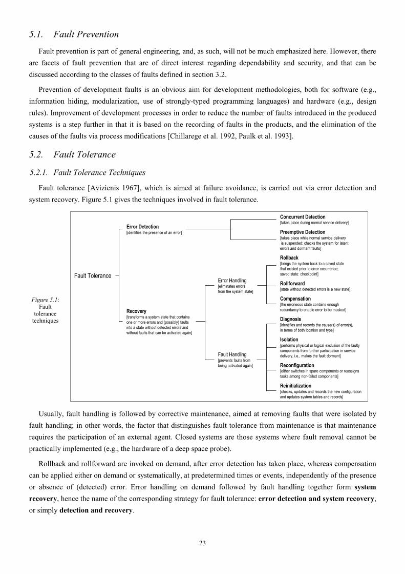
23
5.1. Fault Prevention
Fault prevention is part of general engineering, and, as such, will not be much emphasized here. However, there
are facets of fault prevention that are of direct interest regarding dependability and security, and that can be
discussed according to the classes of faults defined in section 3.2.
Prevention of development faults is an obvious aim for development methodologies, both for software (e.g.,
information hiding, modularization, use of strongly-typed programming languages) and hardware (e.g., design
rules). Improvement of development processes in order to reduce the number of faults introduced in the produced
systems is a step further in that it is based on the recording of faults in the products, and the elimination of the
causes of the faults via process modifications [Chillarege et al. 1992, Paulk et al. 1993].
5.2. Fault Tolerance
5.2.1. Fault Tolerance Techniques
Fault tolerance [Avizienis 1967], which is aimed at failure avoidance, is carried out via error detection and
system recovery. Figure 5.1 gives the techniques involved in fault tolerance.
Figure 5.1: Fault
tolerance techniques
Fault Tolerance
Error Detection[identifies the presence of an error]
Concurrent Detection[takes place during normal service delivery]
Preemptive Detection[takes place while normal service delivery is suspended; checks the system for latent errors and dormant faults]
Recovery[transforms a system state that contains one or more errors and (possibly) faultsinto a state without detected errors and without faults that can be activated again]
Error Handling[eliminates errors from the system state]
Fault Handling[prevents faults from being activated again]
Rollback[brings the system back to a saved state that existed prior to error occurrence; saved state: checkpoint]
Rollforward[state without detected errors is a new state]
Compensation[the erroneous state contains enoughredundancy to enable error to be masked]
Diagnosis[identifies and records the cause(s) of error(s), in terms of both location and type]
Isolation[performs physical or logical exclusion of the faulty components from further participation in service delivery, i.e., makes the fault dormant]
Reconfiguration[either switches in spare components or reassigns tasks among non-failed components]
Reinitialization[checks, updates and records the new configuration and updates system tables and records]
Usually, fault handling is followed by corrective maintenance, aimed at removing faults that were isolated by
fault handling; in other words, the factor that distinguishes fault tolerance from maintenance is that maintenance
requires the participation of an external agent. Closed systems are those systems where fault removal cannot be
practically implemented (e.g., the hardware of a deep space probe).
Rollback and rollforward are invoked on demand, after error detection has taken place, whereas compensation
can be applied either on demand or systematically, at predetermined times or events, independently of the presence
or absence of (detected) error. Error handling on demand followed by fault handling together form system
recovery, hence the name of the corresponding strategy for fault tolerance: error detection and system recovery,
or simply detection and recovery.

24
Fault masking, or simply masking, results from the systematic usage of compensation. Such masking will
conceal a possibly progressive and eventually fatal loss of protective redundancy. So, practical implementations of
masking generally involve error detection (and possibly fault handling), leading to masking and recovery.
It is noteworthy that:
a) rollback and rollforward are not mutually exclusive: rollback may be attempted first; if the error persists,
rollforward may then be attempted;
b) intermittent faults do not necessitate isolation or reconfiguration; identifying whether a fault is intermittent or
not can be performed either by error handling (error recurrence indicates that the fault is not intermittent), or
via fault diagnosis when rollforward is used;
c) fault handling may directly follow error detection, without error handling being attempted,
Preemptive error detection and handling, possibly followed by fault handling, is commonly performed at
system power up. It also comes into play during operation, under various forms such as spare checking, memory
scrubbing, audit programs, or so-called software rejuvenation [Huang et al. 1995], aimed at removing the effects
of software aging before they lead to failure.
Figure 5.2 gives four typical and schematic examples for the various strategies identified for implementing fault
tolerance.
Figure 5.2: Examples for the basic strategies for
implementing fault tolerance
Full Forward Recovery
Error Detection
Compensation
Fault Handling
Intermittentfault•
MaintenanceCall
Solidfault
•
ServiceContinuation
Backward Recovery
Error Detection
Rollback
Fault Handling
MaintenanceCall
• Intermittentfault
Solidfault
•Service Continuation
Masking and recovery
Compensation
Fault Handling
Intermittentfault•
MaintenanceCall
Solidfault
Error Detection
•
ServiceContinuation
Error Detection
Rollforward
Fault Handling
Intermittentfault•
MaintenanceCall
Solidfault
•
ServiceContinuation
Partial Forward Recovery
Detection and Recovery
Forward Recovery
5.2.2. Implementation of Fault Tolerance
The choice of error detection, error handling and fault handling techniques, and of their implementation, is directly
related to, and strongly dependent upon, the underlying fault assumption: the class(es) of faults that can actually be
tolerated depend(s) on the fault assumption that is being considered in the development process, and thus relies on
the independence of redundancies with respect to the process of fault creation and activation. A (widely-used)
method of achieving fault tolerance is to perform multiple computations through multiple channels, either
sequentially or concurrently. When tolerance of physical faults is foreseen, the channels may be of identical
design, based on the assumption that hardware components fail independently. Such an approach has proven to be
adequate for elusive development faults, via rollback [Gray 1986, Huang & Kintala 1995]; it is however not
suitable for the tolerance of solid development faults, which necessitates that the channels implement the same
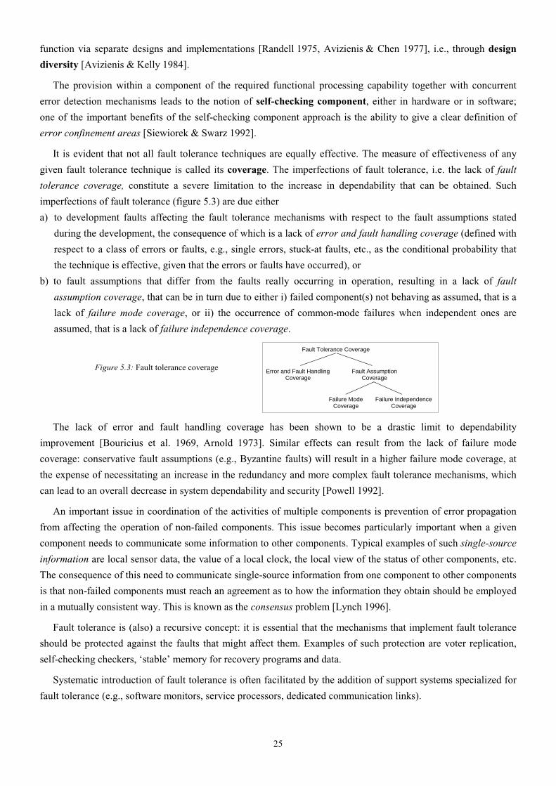
25
function via separate designs and implementations [Randell 1975, Avizienis & Chen 1977], i.e., through design
diversity [Avizienis & Kelly 1984].
The provision within a component of the required functional processing capability together with concurrent
error detection mechanisms leads to the notion of self-checking component, either in hardware or in software;
one of the important benefits of the self-checking component approach is the ability to give a clear definition of
error confinement areas [Siewiorek & Swarz 1992].
It is evident that not all fault tolerance techniques are equally effective. The measure of effectiveness of any
given fault tolerance technique is called its coverage. The imperfections of fault tolerance, i.e. the lack of fault
tolerance coverage, constitute a severe limitation to the increase in dependability that can be obtained. Such
imperfections of fault tolerance (figure 5.3) are due either
a) to development faults affecting the fault tolerance mechanisms with respect to the fault assumptions stated
during the development, the consequence of which is a lack of error and fault handling coverage (defined with
respect to a class of errors or faults, e.g., single errors, stuck-at faults, etc., as the conditional probability that
the technique is effective, given that the errors or faults have occurred), or
b) to fault assumptions that differ from the faults really occurring in operation, resulting in a lack of fault
assumption coverage, that can be in turn due to either i) failed component(s) not behaving as assumed, that is a
lack of failure mode coverage, or ii) the occurrence of common-mode failures when independent ones are
assumed, that is a lack of failure independence coverage.
Figure 5.3: Fault tolerance coverage
Fault Tolerance Coverage
Error and Fault HandlingCoverage
Fault AssumptionCoverage
Failure ModeCoverage
Failure IndependenceCoverage
The lack of error and fault handling coverage has been shown to be a drastic limit to dependability
improvement [Bouricius et al. 1969, Arnold 1973]. Similar effects can result from the lack of failure mode
coverage: conservative fault assumptions (e.g., Byzantine faults) will result in a higher failure mode coverage, at
the expense of necessitating an increase in the redundancy and more complex fault tolerance mechanisms, which
can lead to an overall decrease in system dependability and security [Powell 1992].
An important issue in coordination of the activities of multiple components is prevention of error propagation
from affecting the operation of non-failed components. This issue becomes particularly important when a given
component needs to communicate some information to other components. Typical examples of such single-source
information are local sensor data, the value of a local clock, the local view of the status of other components, etc.
The consequence of this need to communicate single-source information from one component to other components
is that non-failed components must reach an agreement as to how the information they obtain should be employed
in a mutually consistent way. This is known as the consensus problem [Lynch 1996].
Fault tolerance is (also) a recursive concept: it is essential that the mechanisms that implement fault tolerance
should be protected against the faults that might affect them. Examples of such protection are voter replication,
self-checking checkers, ‘stable’ memory for recovery programs and data.
Systematic introduction of fault tolerance is often facilitated by the addition of support systems specialized for
fault tolerance (e.g., software monitors, service processors, dedicated communication links).

26
Reflection, a technique for transparently and appropriately augmenting all relevant actions of an object or
software component, e.g., in order to ensure that these actions can be undone if necessary, can be used in object-
oriented software and through the provision of middleware [Fabre et al. 1995].
Fault tolerance applies to all classes of faults. Protection against intrusions traditionally involves cryptography
and firewalls. Some mechanisms of error detection are directed towards both non-malicious and malicious faults
(e.g., memory access protection techniques). Intrusion detection is usually performed via likelihood checks
[Forrest et al. 1996, Debar et al. 1998]. Approaches and schemes have been proposed for tolerating:
• intrusions and physical faults, via information fragmentation and dispersal [Fray et al. 1986, Rabin 1989],
• malicious logic, and more specifically to viruses, either via control flow checking [Joseph & Avizienis 1988a],
or via design diversity [Joseph & Avizienis 1988b],
• intrusions, malicious logic, vulnerabilities due to physical or development faults, via server diversity [Valdes et
al. 2004].
Finally, it is worth mentioning that a) several synonyms exist for fault tolerance : self-repair, self-healing,
resilience, and that b) the term recovery-oriented computing [Fox & Patterson 2003] has recently been
introduced for what is essentially a fault tolerance approach to achieving overall system dependability, i.e., at the
level above individual computer systems, in which the failures of these individual systems constitute the faults to
be tolerated.
5.3. Fault Removal
In this section, we consider fault removal during system development, and during system use.
5.3.1. Fault removal during development
Fault removal during the development phase of a system life-cycle consists of three steps: verification,
diagnosis, correction. We focus in what follows on verification, that is the process of checking whether the system
adheres to given properties, termed the verification conditions; if it does not, the other two steps have to be
undertaken: diagnosing the fault(s) that prevented the verification conditions from being fulfilled, and then
performing the necessary corrections. After correction, the verification process should be repeated in order to
check that fault removal had no undesired consequences; the verification performed at this stage is usually termed
non-regression verification.
Checking the specification is usually referred to as validation [Boehm 1979]. Uncovering specification faults
can happen at any stage of the development, either during the specification phase itself, or during subsequent
phases when evidence is found that the system will not implement its function, or that the implementation cannot
be achieved in a cost-effective way.
Verification techniques can be classified according to whether or not they involve exercising the system.
Verifying a system without actual execution is static verification. Such verification can be conducted:
• on the system itself, in the form of a) static analysis (e.g., inspections or walk-through, data flow analysis,
complexity analysis, abstract interpretation, compiler checks, vulnerability search, etc.) or b) theorem proving;
• on a model of the system behavior, where the model is usually a state-transition model (Petri nets, finite or
infinite state automata), leading to model checking.

27
Verifying a system through exercising it constitutes dynamic verification; the inputs supplied to the system
can be either symbolic in the case of symbolic execution, or actual in the case of verification testing, usually
simply termed testing.
Figure 5.4 summarizes the verification approaches.
Figure 5.4: Verification approaches
Verification
System not exercised System exercised
Static verification Dynamic verification
System Behavior model
Symbolic inputs
Actuallinputs
StaticAnalysis
TheoremProving
ModelChecking
SymbolicExecution
Testing
Exhaustive testing of a system with respect to all its possible inputs is generally impractical. The methods for
the determination of the test patterns can be classified according to two viewpoints: criteria for selecting the test
inputs, and generation of the test inputs.
Figure 5.5 summarizes the various testing approaches according to test selection. The upper part of the figure
identifies the elementary testing approaches. The lower part of the figure gives the combination of the elementary
approaches, where a distinction is made between hardware and software testing, since hardware testing is mainly
aimed at removing production faults, whereas software testing is concerned only with development faults:
hardware testing is usually fault-based, whereas software testing is criteria-based, with the exception of mutation
testing, which is fault-based.
Figure 5.5: Testing approaches according to test
pattern selection
System model
Function
Functional testing
Sructure
Structural testing
Testing purpose
Conformance testing
System ability to deliver
specifiedservice
Fault-finding testing
Fault revealing
Fault model
Fault-based testing
Existence
Criteria-based testing
Absence
Hardware(manufacturing
faults)
● ● ●Functional
testing
Software
● ● ●
● ● ●
● ● ●
● ● ●
(developmentfaults)
Mutationtesting
Functional testing
Functional testing
Structural testing
Structural testing
The generation of the test inputs may be deterministic or probabilistic:
• in deterministic testing, test patterns are predetermined by a selective choice;
• in random, or statistical, testing, test patterns are selected according to a defined probability distribution on
the input domain; the distribution and the number of input data are determined according to the given fault
model or criteria.
28
Observing the test outputs and deciding whether or not they satisfy the verification conditions is known as the
oracle problem. The verification conditions may apply to the whole set of outputs or to a compact function of the
latter (e.g., a system signature when testing for physical faults in hardware, or to a ‘partial oracle’ when testing for
development faults of software [Weyuker 1982]). When testing for physical faults, the results — compact or not
— anticipated from the system under test for a given input sequence are determined by simulation or from a
reference system (golden unit). For development faults, the reference is generally the specification; it may also be
a prototype, or another implementation of the same specification in the case of design diversity (back-to-back
testing).
Verification methods can be used in combination. For instance, symbolic execution may be used to facilitate
the determination of the testing patterns, theorem proving may be used to check properties of infinite state models
[Rushby 1995], mutation testing may be used to compare various testing strategies [Thevenod-Fosse et al. 1991].
As verification has to be performed throughout a system’s development, the above techniques are applicable to
the various forms taken by a system during its development: prototype, component, etc.
The above techniques apply also to the verification of fault tolerance mechanisms, especially a) formal static
verification [Rushby 1992], and b) testing that necessitates faults or errors to be part of the test patterns, that is
usually referred to as fault injection [Avresky et al. 1996].
Verifying that the system cannot do more than what is specified is especially important with respect to what the
system should not do, thus with respect to safety and security (e.g., penetration testing).
Designing a system in order to facilitate its verification is termed design for verifiability. This approach is
well-developed for hardware with respect to physical faults, where the corresponding techniques are termed
design for testability.
5.3.2. Fault removal during use
Fault removal during the use of a system is corrective or preventive maintenance. Corrective maintenance aims
to remove faults that have produced one or more errors and have been reported, while preventive maintenance is
aimed at uncovering and removing faults before they might cause errors during normal operation. The latter faults
include a) physical faults that have occurred since the last preventive maintenance actions, and b) development
faults that have led to errors in other similar systems. Corrective maintenance for development faults is usually
performed in stages: the fault may be first isolated (e.g., by a workaround or a patch) before the actual removal is
completed. These forms of maintenance apply to non-fault-tolerant systems as well as to fault-tolerant systems,
that can be maintainable on-line (without interrupting service delivery) or off-line (during service outage).
5.4. Fault Forecasting
Fault forecasting is conducted by performing an evaluation of the system behavior with respect to fault
occurrence or activation. Evaluation has two aspects:
• qualitative, or ordinal, evaluation, that aims to identify, classify, and rank the failure modes, or the event
combinations (component failures or environmental conditions) that would lead to system failures;
• quantitative, or probabilistic, evaluation, that aims to evaluate in terms of probabilities the extent to which
some of the attributes are satisfied; those attributes are then viewed as measures.
29
The methods for qualitative and quantitative evaluation are either specific (e.g., failure mode and effect
analysis for qualitative evaluation, or Markov chains and stochastic Petri nets for quantitative evaluation), or they
can be used to perform both forms of evaluation (e.g., reliability block diagrams, fault-trees).
The two main approaches to probabilistic fault-forecasting, aimed to derive probabilistic estimates, are
modeling and (evaluation) testing. These approaches are complementary, since modeling needs data on the basic
processes modeled (failure process, maintenance process, system activation process, etc.), that may be obtained
either by testing, or by the processing of failure data.
Modeling can be conducted with respect to a) physical faults, b) development faults, or c) a combination of
both. Although modeling is usually performed with respect to non-malicious faults, attempts to perform modeling
with respect to malicious faults are worth mentioning [Ortalo et al. 1999, Sanders et al. 2002]. Modeling is
composed of two phases:
• construction of a model of the system from the elementary stochastic processes that model the behavior of the
components of the system and their interactions; these elementary stochastic processes relate to failure, to
service restoration including repair, and possibly to system duty cycle or phases of activity;
• processing the model to obtain the expressions and the values of the dependability measures of the system.
Generally, several services can be distinguished, as well as two or more modes of service, e.g., ranging from
full capacity to emergency service. These modes distinguish less and less complete service deliveries.
Performance-related measures of dependability are usually subsumed into the notion of performability [Meyer
1978, Smith & Trivedi 1988].
Reliability growth models, either for hardware, for software, or for both, are used to perform reliability
predictions from data about past system failures.
Evaluation testing can be characterized using the viewpoints defined in section section 5.3.1, i.e., conformance,
functional, non fault-based, statistical, testing, although it is not — primarily — aimed at verifying a system. A
major concern is that the input profile should be representative of the operational profile [Musa 1992], hence the
usual name of evaluation testing is operational testing.
When evaluating fault-tolerant systems, the coverage provided by error and fault handling mechanisms has a
drastic influence [Bouricius et al. 1969, Arnold 1973] on dependability measures. The evaluation of coverage can
be performed either through modeling or through testing, i.e., fault injection.
The notion of dependability & security benchmark, that is a procedure to assess measures of the behavior of
a computer system in the presence of faults, enables the integration of the various techniques of fault forecasting in
a unified framework. Such a benchmark enables a) characterization of the dependability and security of a system,
and b) comparison of alternative or competitive solutions according to one or several attributes [Kanoun et al.
2004].
5.5. Relationships between the Means for Dependability and Security
All the ‘how to’s’ that appear in the definitions of fault prevention, fault tolerance, fault removal, fault
forecasting given in section 2 are in fact goals that can rarely if ever be fully reached, since all the design and
analysis activities are human activities, and thus imperfect. These imperfections bring in relationships that explain
why it is only the combined utilization of the above activities — preferably at each step of the design and
implementation process — that can best lead to a dependable & secure computing system. These relationships can

30
be sketched as follows: in spite of fault prevention by means of development methodologies and construction rules
(themselves imperfect in order to be workable), faults may occur. Hence there is a need for fault removal. Fault
removal is itself imperfect (i.e., all faults cannot be found, and another fault(s) may be introduced when removing
a fault), and off-the-shelf components — hardware or software — of the system may, and usually do, contain
faults; hence the importance of fault forecasting (besides the analysis of the likely consequences of operational
faults). Our increasing dependence on computing systems brings in the requirement for fault tolerance, that is in
turn based on construction rules; hence the need again for applying fault removal and fault forecasting to fault
tolerance mechanisms themselves. It must be noted that the process is even more recursive than it appears above:
current computing systems are so complex that their design and implementation need software and hardware tools
in order to be cost-effective (in a broad sense, including the capability of succeeding within an acceptable time
scale). These tools themselves have to be dependable and secure, and so on.
The preceding reasoning illustrates the close interactions between fault removal and fault forecasting, and
motivates their gathering into dependability & security analysis, aimed at reaching confidence in the ability to
deliver a service that can be trusted, whereas the grouping of fault prevention and fault tolerance constitutes
dependability & security provision, aimed at providing the ability to deliver a service that can be trusted.
Another grouping of the means is the association of a) fault prevention and fault removal into fault avoidance,
i.e., how to aim for fault-free systems, and of b) fault tolerance and fault forecasting into fault acceptance, i.e.,
how to live with systems that are subject to faults. Figure 5.6 illustrates the groupings of the means for
dependability. It is noteworthy that, when focusing on security, such analysis is called security evaluation
[ISO/IEC 1999].
Figure 5.6: Groupings of the means for dependability and
security
FaultAvoidance
Fault Acceptance
Dependabilityand Security
Analysis
Dependabilityand Security
Provision
Means forDependabilityand Security
Fault Prevention � �
Fault Forecasting � �
Fault Removal � �
Fault Tolerance � �
Besides highlighting the need to assess the procedures and mechanisms of fault tolerance, the consideration of
fault removal and fault forecasting as two constituents of the same activity — dependability analysis — leads to a
better understanding of the notion of coverage, and thus of an important problem introduced by the above
recursion: the assessment of the assessment, or how to reach confidence in the methods and tools used in building
confidence in the system. Coverage refers here to a measure of the representativeness of the situations to which
the system is subjected during its analysis compared to the actual situations that the system will be confronted with
during its operational life. The notion of coverage as defined here is very general; it may be made more precise by
indicating its range of application, e.g.: coverage of a software test with respect to the software text, control graph,
etc., coverage of an integrated circuit test with respect to a fault model, coverage of fault tolerance with respect to
a class of faults, coverage of a development assumption with respect to reality.
The assessment of whether a system is truly dependable and, if appropriate, secure — i.e., the delivered service
can justifiably be trusted — goes beyond the analysis techniques as they have been addressed in the previous
sections for, at least, the three following reasons and limitations:
• precise checking of the coverage of the design or validation assumptions with respect to reality (e.g., relevance
to actual faults of the criteria used for determining test inputs, fault hypotheses in the design of fault tolerance

31
mechanisms) would imply a knowledge and a mastering of the technology used, of the intended utilization of
the system, etc., that exceeds by far what is generally achievable;
• the evaluation of a system for some attributes of dependability, and especially of security with respect to
certain classes of faults is currently considered as unfeasible or as yielding non-significant results, because
probability-theoretic bases do not exist or are not yet widely accepted; examples are safety with respect to
accidental development faults, security with respect to intentional faults;
• the specifications with respect to which analysis is performed are likely to contain faults — as does any system.
Among the numerous consequences of this state of affairs, let us mention:
• the emphasis placed on the development process when assessing a system, i.e., on the methods and techniques
utilized in development and how they are employed; in some cases, a grade is assigned and delivered to the
system according to a) the nature of the methods and techniques employed in development, and b) an
assessment of their utilization [Paulk et al. 1993, RTCA/EUROCAE 1992, ISO/IEC 1999, SQUALE 1999];
• the presence, in the specifications of some fault-tolerant systems (in addition to probabilistic requirements in
terms of dependability measures), of a list of types and numbers of faults that are to be tolerated; such a
specification would not be necessary if the limitations mentioned above could be overcome (such specifications
are classical in aerospace applications, under the form of a concatenation of “fail-operational” (FO) or “fail-
safe” (FS) requirements, e.g., FO/FS, or FO/FO/FS, etc.).
6. Conclusion
Increasingly, individuals and organizations are developing or procuring sophisticated computing systems on
whose services they need to place great trust — whether to service a set of cash dispensers, control a satellite
constellation, an airplane, a nuclear plant, or a radiation therapy device, or to maintain the confidentiality of a
sensitive data base. In differing circumstances, the focus will be on differing properties of such services — e.g., on
the average real-time response achieved, the likelihood of producing the required results, the ability to avoid
failures that could be catastrophic to the system’s environment, or the degree to which deliberate intrusions can be
prevented. Simultaneous consideration of dependability and security provides a very convenient means of
subsuming these various concerns within a single conceptual framework. It includes as special cases such
properties as availability, reliability, safety, confidentiality, integrity, maintainability. It also provides the means of
addressing the problem that what a user usually needs from a system is an appropriate balance of these properties.
A major strength of the concept formulated in this paper, is its integrative nature; this enables the more
classical notions of reliability, availability, safety, confidentiality, integrity, maintainability to be put into
perspective. The fault-error-failure model is central to the understanding and mastering of the various threats that
may affect a system, and it enables a unified presentation of these threats, while preserving their specificities via
the various fault classes that can be defined. The model provided for the means for achieving dependability and
security is extremely useful, as those means are much more orthogonal to each other than the more classical
classification according to the attributes of dependability, with respect to which the development of any real
system has to perform trade-offs, since these attributes tend to conflict with each other. The refinement of the basic
definitions given in section 2 leads to a refined dependability and security tree, as given by figure 6.1.

32
Figure 6.1: A refined dependability and
security tree
Threats
Attributes
Means
Availability
Reliability
Safety
Confidentiality
Integrity
Maintainability
Faults
Development faults
Physical faults
Interaction faults
Errors
Failures
Service failures
Development failures
Dependability failures
Fault Prevention
Fault Tolerance
Fault Removal
Fault Forecasting
Error DetectionConcurrent Detection
Preemptive Detection
RecoveryError Handling
Fault Handling
Static Verification
Dynamic VerificationVerification
Diagnosis
Correction
Non-regression Verification
Ordinal Evaluation
Probabilistic EvaluationModeling
Operational Testing
Security
and
Dependability
Acknowledgements
The authors are pleased to acknowledge many fruitful interactions with numerous colleagues, in particular Jean
Arlat, Alain Costes, Yves Deswarte, Cliff Jones, and especially with fellow members of IFIP WG 10.4 on
DependableComputing and Fault Tolerance. Early part of this work received support from the CNRS-NSF grant
“Tolerance to intentional faults”.
References [Arnold 1973] T.F. Arnold, “The concept of coverage and its effect on the reliability model of repairable systems”, IEEE
Trans. on Computers, vol. C-22, June 1973, pp. 251-254.
[Avresky et al. 1996] D. Avresky, J. Arlat, J.C. Laprie, Y. Crouzet, “ Fault injection for formal testing of fault tolerance”, IEEE Trans. on Reliability, vol. 45, no. 3, Sep. 1996, pp. 443-455.
[Avizienis 1967] A. Avizienis, “Design of fault-tolerant computers”, in Proc. 1967 Fall Joint Computer Conf., AFIPS Conf. Proc. Vol. 31, pp. 733-743, 1967.
[Avizienis & Chen, 1977] A. Avizienis and L. Chen, “On the implementation of N-version programming for software fault tolerance during execution”, in Proc. IEEE COMPSAC 77, Nov. 1977, pp. 149-155.
[Avizienis & He 1999] A. Avizienis, Y. He, “Microprocessor entomology: a taxonomy of design faults in COTS microprocessors”, in Dependable Computing for Critical Applications 7, C.B. Weinstock and J. Rushby, eds, IEEE CS Press, 1999, pp. 3-23.
33
[Avizienis & Kelly 1984] A. Avizienis, J.P.J. Kelly, “Fault tolerance by design diversity: concepts and experiments”, Computer, vol. 17, no. 8, Aug. 1984, pp. 67-80.
Boehm 1979 B.W. Boehm, “Guidelines for verifying and validating software requirements and design specifications”, in Proc. EURO IFIP’79, London, Sep. 1979, pp. 711-719.
[Bouricius et al. 1969] W.G.Bouricius, W.C. Carter, and P.R. Schneider, “Reliability modeling techniques for self-repairing computer systems”, in Proc. of 24th National Conference of ACM, 1969, pp. 295-309.
[Cachin et al. 2000] C. Cachin, J. Camenisch, M. Dacier, Y. Deswarte, J. Dobson, D. Horne, K. Kursawe, J.C. Laprie, J.C. Lebraud, D. Long, T. McCutcheon, J. Muller, F. Petzold, B. Pfitzmann, D. Powell, B. Randell, M. Schunter, V. Shoup, P. Verissimo, G. Trouessin, R.J. Stroud, M. Waidner, I. Welch, “Malicious- and Accidental-Fault Tolerance in Internet Applications: reference model and use cases”, LAAS report no. 00280, MAFTIA, Project IST-1999-11583, Aug. 2000, 113p.
[Castelli et al. 2001] V. Castelli, R.E. Harper, P. Heidelberger, S.W. Hunter, K.S. Trivedi, K. Vaidyanathan, W.P. Zeggert, “Proactive management of software aging”, IBM J. Res.& Dev., vol. 45, no. 2, March 201, pp. 311-332.
[CCITT 1984] Termes et définitions concernant la qualité de service, la disponibilité et la fiabilité, Recommandation G 106, CCITT, 1984; in French (“Terms and definitions characterizing quality of service, availability and reliability”).
[CEC 1991] Information Technology Security Evaluation Criteria, Harmonized criteria of France, Germany, the Netherlands, the United Kingdom, Commission of the European Communities, 1991.
[Chillarege et al. 1992] R. Chillarege, I. S. Bhandari, J. K. Chaar, J. Halliday, D. S. Moebus, B. K. Ray et M.-Y. Wong, “Orthogonal Defect Classification—A Concept for In-Process Measurements”, IEEE Trans. on Software Engineering, 18 (11), 1992, pp.943-956.
[Cristian 1991] F. Cristian, “Understanding Fault-Tolerant Distributed Systems”, Com. of the ACM, vol. 34, no. 2, 1991, pp. 56-78.
[Debar et al. 1998] H. Debar, M. Dacier, M. Nassehi, A. Wespi, “Fixed vs. variable-length patterns for detecting suspicious process behavior”, in Proc. 5th European Symp. on Research in Computer Security, Louvain-la-Neuve, Belgium, Sept. 1998, Lecture Notes in Computer Science 1485, J.J. Quisquater, Y. Deswarte, C. Meadows, D. Gollmann, eds., Springer, pp. 1-15.
[Ellison et al. 1999] R.J. Ellison, D.A. Fischer, R.C. Linger, H.F. Lipson, T. Longstaff, N.R. Mead, “Survivable network systems: an emerging discipline”, Technical Report CMU/SEI-97-TR-013, November 1997, revised May 1999.
[Fabre et al 1995] J.C. Fabre, V. Nicomette, T. Perennou, R.J. Stroud, and Z. Wu. "Implementing fault tolerant applications using reflective object-oriented programming", in Proc 25th IEEE Int. Symp. on Fault-Tolerant Computing (FTCS-25), 1995, pp. 489-498.
[Forrest et al. 1996] S. Forrest, S.A. Hofmeyr, A. Somayaji, T.A. Longstaff, “A sense of self for Unix processes”, in Proc. 1996 IEEE Symp. on Security and Privacy, Oakland, California, May 1996, pp. 120-128.
[Fox & Patterson 2003] A. Fox, D. Patterson, "Self-repairing computers", Scientific American, vol. 288, no. 6, 2003, pp. 54-61.
[Fray et al. 1986] J.M. Fray, Y. Deswarte, D. Powell, “Intrusion tolerance using fine-grain fragmentation-scattering”, in Proc. 1986 IEEE Symp. on Security and Privacy, Oakland, April 1986, pp. 194-201.
[FTCS 1982] Special session “Fundamental concepts of fault tolerance”, in Proc. 12th IEEE Int. Symp. on Fault-Tolerant Computing (FTCS-12), Santa Monica, California, June 1982:
D.E. Morgan, “Report of subcommittee on models, fundamental concepts, and terminology”, pp. 3-5. A. Avizienis, “The four-universe information system model for the study of fault tolerance”, pp. 6-13. H. Kopetz, “The failure fault model”, pp. 14-17. J.C. Laprie, A. Costes, “Dependability: a unifying concept for reliable computing”, pp. 18-21. A.S. Robinson, “A user oriented perspective of fault-tolerant system models and terminologies”, pp. 22-28. T. Anderson, P.A. Lee, “Fault tolerance terminology proposals”, pp. 29-33. P.A. Lee, D.E. Morgan, editors, “Fundamental concepts of fault-tolerant computing”, pp. 34-38.
[Ganek & Korbi 2003] A.G. Ganek, T.A. Korbi, "The dawning of the autonomic computing era", IBM Systems Journal, vol. 42, no. 1, 2003, pp. 5-18.
[Gray 1986] J.N. Gray, “Why do computers stop and what can be done about it?”, in Proc. 5th Symp. on Reliability in Distributed Software and Database Systems, Los Angeles, Jan. 1986, pp. 3-12.
[Gray 2001] J. Gray, “Functionality, Availability, Agility, Manageability, Scalability -- the New Priorities of Application Design”, in Proc. HPTS 2001, Asilomar, April 2001.
[Grigonis 2001] R. Grigonis, “Fault-resilience for communications convergence”, Special Supplement to CMP Media’s Converging Communications Group, Spring 2001.
[Hosford 1960] J.E. Hosford, “Measures of dependability”, Operations Research, vol. 8, no. 1, 1960, pp. 204-206.

34
[Huang et al. 1995] Y. Huang, C. Kintala, N. Kolettis, N.D. Fulton, “Software rejuvenation: analysis, module and applications”, in Proc. 25th IEEE Int. Symp. on Fault-Tolerant Computing (FTCS-25), Pasadena, California, June 1995, pp. 381-390.
[Huang & Kintala 1995] Y. Huang, C. Kintala, “Software fault tolerance in the application layer”, in Software Fault Tolerance, Michael Lyu Ed., Wiley, 1995, pp. 231-248.
[IEC 1992] Industrial-process measurement and control — Evaluation of system properties for the purpose of system assessment. Part 5: Assessment of system dependability, Draft, Publication 1069-5, International Electrotechnical Commission (IEC) Secretariat, Feb. 1992.
[IEC 1998] Functional Safety of Electical/Electronic/Programmable Electronic Safety-Related Systems, IEC Standard 61505, 1998.
[ISO 1992] Quality Concepts and Terminology, Part one: Geberic Terms and Definitions, Document ISO/TC 176/SC 1 N 93, Feb. 1992.
[ISO/IEC 1999] Common Criteria for Information Technology Security Evaluation, ISO/IEC Standard 15408, August 1999.
[Jacob 1991] J. Jacob. “The Basic Integrity Theorem”, in Proc. Int. Symp. on Security and Privacy, Oakland, CA, USA, 1991, pp. 89-97.
[Johnson 1995] J. Johnson, “Chaos: the dollar drain of IT project failures”, Application Development Trends, January 1995, pp. 41-47. Subsequent updates at <www.standishgroup.com>.
[Joseph & Avizienis 1988a] M.K. Joseph, A. Avizienis, “A fault tolerance approach to computer viruses”, in Proc. 1988 Symp. on Security and Privacy, Oakland, April 1988, pp. 52-58.
[Joseph & Avizienis 1988b] M.K. Joseph, A. Avizienis, “Software fault tolerance and computer security: a shared problem”, in Proc. Ann. Joint Conf. on Software Quality and Reliability, Arlington, March 1988, pp. 428-432.
[Kanoun et al. 2004] K. Kanoun, H. Madeira, Y. Crouzet, M. Dal Cin, F. Moreira, J.C. Ruiz Garcia, eds., “DBench Dependability Benchmarks”, DBench, Project IST-2000-25425, May 2004, 233 p.
[Lamport et al. 1982] L. Lamport, R. Shostak, M. Pease, “The Byzantine generals problem”, ACM Trans.on Programming Languages and Systems, vol. 4, no. 3, July 1982, pp. 382-401.
[Landwehr et al. 1994] C.E. Landwher, A.R. Bull, J.P. McDermott, W.S. Choi, “A Taxonomy of Computer Program Security Flaws”, ACM Computing Surv., vol. 26, no. 3, 1994, pp. 211-254.
[Laprie 1985] J.C. Laprie. Dependable computing and fault tolerance: concepts and terminology. In Proc. 15th IEEE Int. Symp. on Fault-Tolerant Computing (FTCS-15), Ann Arbor, June 1985, pp. 2-11, .
[Laprie 1992] J.C. Laprie, editor, Dependability: Basic Concepts and Terminology, Springer-Verlag, 1992.
[Laprie 1995] J.C. Laprie, “Dependability - its attributes, impairments and means”, in Predictably Dependable Computing Systems, B. Randell, J.C. Laprie, H. Kopetz, B. Littlewood (eds.), Springer, 1995, pp. 3-24
[Lynch 1996] N.A. Lynch, Distributed Algorithms, Morgan Kaufmann 1996
[McLean 1985] J. McLean, “A Comment on the ‘Basic Security Theorem’ of Bell and LaPadula”, Information Processing Letters, vol. 20, no. 2, 15 (1985), pp.67-70.
[Meyer 1978] J.F. Meyer, “On evaluating the performability of degradable computing systems”, in Proc. 8th IEEE Int. Symp. on Fault-Tolerant Computing (FTCS-8), Toulouse, France, June 1978, pp. 44-49.
[Musa 1992] J. Musa, “The Operational Profile in Software Reliability Engineering: An Overview”, Proc. 3rd IEEE Int. Symp. on Software Reliability Engineering (ISSRE’92), pp. 140-154, NC, USA, IEEE Computer Society Press, 1992.
[NIST 1995] An Introduction to Computer Security: The NIST Handbook, Special Publication 800-12, National Institute of Standards and Technology, 1995.
[NSTC 2000] National Science and Technology Council, Information Technology Frontiers for a New Millennium, Supplement to to the Prsident’s FY 2000 Budget.
[Ortalo et al. 1999] R. Ortalo, Y. Deswarte, M. Kaaniche, "Experimenting with Quantitative Evaluation Tools for Monitoring Operational Security", IEEE Transactions on Software Engineering, Vol.25, N°5, 1999, Sept./Oct. 1999, pp.633-650.
[Parnas 1972] D. Parnas, “On the criteria to be used in decomposing systems into modules”, Comunications of the ACM, vol. 15, no. 12, Dec. 1972, pp. 1053-1058.
[Paulk et al. 1993] M.C. Paulk, B. Curtis, M.B. Chrissis, C.V. Weber, “Capability maturity model for software”, Software Engineering Institute, report CMU/SEI-93-TR-24, ESC-TR-93-177, Feb. 1993.
[Pfleeger 2000] C.P. Pfleeger, “Data security”, in Encyclopedia of Computer Science, A.Ralston, E.D. Reilly, D. Hemmendinger, eds, Nature Publishing Group, 2000, pp. 504-507.
[Powell et al. 1988] D. Powell, G. Bonn, D. Seaton, P. Verissimo, F. Waeselynck, “The Delta-4 approach to dependability in open distributed computing systems”, in Proc. 18th IEEE Int. Symp. on Fault-Tolerant Computing (FTCS-18), Tokyo, Japan, June 1988, pp. 246-251.

35
[Powell 1992] D. Powell, “Failure Mode Assumptions and Assumption Coverage”, Proc. 22nd IEEE Int. Symp. on Fault-Tolerant Computing (FTCS-22), Boston, June 1992, pp. 386-395.
[Powell & Stroud 2003] D. Powell, R. Stroud, editors, “Conceptual Model and Architecture of MAFTIA”, MAFTIA, Project IST-1999-11583, Jan. 2003, 123p.
[Rabin 1989] M.O. Rabin, “Efficient dispersal of information for security, load balancing and fault tolerance”, Journal of the ACM, vol. 36, no. 2, April 1989, pp. 335-348.
[Randell 1975] B. Randell, “System structure for software fault tolerance”, IEEE Trans. on Software Engineering, vol. SE-1, no. 2, June 1975, pp. 220-232.
[RTCA/EUROCAE 1992] Software considerations in airborne systems and equipment certification, DO-178-B/ED-12-B, Requirements and Technical Concepts for Aviation/European Organisation for Civil Aviation Equipement, 1992.
[Rushby 1992] J. Rushby, “Formal Specification and Verification of a Fault-Masking and Transient-Recovery Model for Digital Flight Control Systems”, Proc. 2nd Int. Symp. on Formal Techniques in Real Time and Fault-Tolerant Systems, Nijmegen, Netherlands, Springer-Verlag, 1992. Lectures Notes in Computer Science, vol. 571, pp. 237-258.
[Rushby 1995] J. Rushby, “Formal methods and their role in the certification of critical systems”, Technical Report CSL-95-1, SRI International, 1995.
[Sanders et al. 2002] W. H. Sanders, M. Cukier, F. Webber, P. Pal, and R. Watro, “Probabilistic validation of intrusion tolerance,” in Supplemental Volume Int. Conference on Dependable Systems & Networks (DSN-2002), Washington, DC, June 2002, pp. B–78–B–79.
[Schneider 1999] F. Schneider, ed., Trust in Cyberspace, National Academy Press, 1999.
[Siewiorek & Swarz 1992] D.P. Siewiorek, R.S. Swarz, Reliable Computer Systems, Design and Evaluation, Digital Press, 1992
[Smith & Trivedi 1988] R.M. Smith, K.S. Trivedi, A.V. Ramesh, “Performability analysis: measures, an algorithm, and a case study”, IEEE Trans. on Computers, vol. 37, no. 4, April 1988, pp. 406-417.
[SQUALE 1999] Dependability Assessment Criteria, SQUALE project (ACTS95/AC097), Jan. 1999, LAAS Report no. 98456.
[Thevenod-Fosse et al. 1991] P. Thevenod-Fosse, H. Waeselynck, Y. Crouzet, “An experimental study on softawre structural testing: deterministic testing versus random input generation”, in Proc. 21st IEEE Int. Symp. on Fault-Tolerant Computing (FTCS-21), Montreal, June 1981, pp. 410-417.
[US DOT 1998] USA Department of Transportation, Office of Inspector General, Audit Report: Advance Automation System, Report No. AV-1998-113, April 15, 1998.
[Valdes et al. 2004] A. Valdes, M. Almgren, S. Cheung, Y. Deswarte, B. Dutertre, J. Levy, H. Saïdi, V. Stavridou, T. Uribe, “An Adaptative Intrusion-Tolerant Server Architecture”, in Proc. 10th International Workshop on Security Protocols, Cambridge (GB), 17-19 April 2002, Eds B. Christianson, B. Crispo, J.A. Malcolm, M. Roe, LNCS n°2845, Springer, ISBN 3-540-20830-5, 2004, pp.158-178.
[Weyuker 1982] E.J. Weyuker, “On testing non-testable programs”, The Computer Journal, vol. 25, no. 4, 1982, pp. 465-470.
[Wood 1994] A. Wood, “NonStop availability in a client/server environment”, Tandem Technical Report 94.1, March 1994.
Index of Definitions Accidental fault 3.2.1 Accountability 4.3 Active fault 2.2 Adaptive maintenance 3.1 Atomic 2.1 Augmentive maintenance 3.1 Authenticity 4.3 Autonomic computing 4.3 Availability 2.3 Back-to-back testing 5.3.1 Backward recovery 5.2.1 Behavior Byzantine failure 3.3.1 Catastrophic failure 3.3.1 Commission fault 3.2.3 Common-mode failure 3.5 Compensation 5.2.1 Component 2.1 Computer-based systems 2 Concurrent detection 5.2.1
Confidentiality 2.3 Configuration fault 3.2.3 Consistency 3.3.1 Consistent failure 3.3.1 Content failure 3.3.1 Correct service 2.2 Corrective maintenance 3.1 Coverage 5.5 Degraded mode 2.2 Deliberate fault 3.2.1 Denial of service 3.2.4 Dependability & security analysis 5.5 Dependability & security benchmark 5.4 Dependability & security failure 3.3.3 Dependability & security specification 2.3 Dependability 2.3 Dependability provision 5.5 Dependence 2.3
Design diversity 5.2.2 Design for testability 5.3.1 Design for verifiability 5.3.1 Detectability 3.3.1 Detected error 3.4 Detection and recovery 5.2.1 Deterministic testing 5.3.1 Development environment 3.1 Development failure 3.3.2 Development fault 3.2.1 Development phase 3.1 Diagnosis 5.2.1 Dormant fault 2.2 Downgrading 3.3.2 Dynamic verification 5.3.1 Early timing failure 3.3.1 Elusive fault 3.5 Environment 2.1 Erratic failure 3.3.1 Error 2.2
36
Error detection and system recovery 5.2.1 External fault 3.2.1 External state 2.1 Fail-controlled system 3.3.1 Fail-halt system 3.3.1 Fail-passive system 3.3.1 Fail-safe system 3.3.1 Fail-silent system 3.3.1 Fail-stop system 3.3.1 Failure 2.2 Failure domain 3.3.1 Failure severity 2.2 False alarm 3.3.1 Fault 2.2 Fault acceptance 5.5 Fault activation 3.5 Fault activation reproducibility 3.5 Fault avoidance 5.5 Fault forecasting 2.4 Fault injection 5.3.1 Fault masking 5.2.1 Fault prevention 2.4 Fault removal 2.4 Fault tolerance 2.4 Forward recovery 5.2.1 Function 2.1 Functional specification 2.1 Functional testing 5.3.1 Golden unit 5.3.1 Halt 3.3.1 Halt failure 3.3.1 Hard fault 3.5 Hardware fault 3.2.1 High Confidence 4.4 Human-made fault 3.2.1 Incompetence fault 3.2.1 Inconsistent failure 3.3.1 Independent faults 3.5 Integrity 2.3 Interaction fault 3.2.1 Intermittent fault 3.5 Internal fault 3.2.1 Internal state 2.1 Intrusion attempt 3.2.4 Isolation 5.2.1 Late timing failure 3.3.1 Latent error 3.4 Logic bomb 3.2.4 Maintainability 2.3
Maintenance 3.1 Malicious fault 3.2.1 Malicious logic fault 3.2.4 Masking 5.2.1 Masking and recovery 5.2.1 Minor failure 3.3.1 Multiple faults 3.5 Multiple related errors 3.4 Mutation testing 5.3.1 Natural fault 3.2.1 Non-deliberate fault 3.2.1 Non-malicious fault 3.2.1 Non-regression verification 5.3.1 Non-repudiability 4.3 Omission 3.2.3 Omission fault 3.2.3 Operational fault 3.2.1 Operational testing 5.4 Oracle problem 5.3.1 Ordinal evaluation 5.4 Overrun 3.3.2 Partial development failure 3.3.2 Partial failure 2.2 Penetration testing 5.3.1 Performability 5.4 Permanent fault 3.2.1 Physical fault 3.2.1 Preemptive detection 5.2.1 Preventive maintenance 3.1 Probabilistic evaluation 5.4 Provider 2.1 Qualitative evaluation 5.4 Quantitative evaluation 5.4 Random testing 5.3.1 Reconfiguration 5.2.1 Reconfiguration fault 3.2.3 Recovery-oriented computing 5.2.2 Reinitialization 5.2.1 Related faults 3.5 Reliability 2.3 Resilience 5.2.2 Robustness 4.3 Rollback 5.2.1 Rollforward 5.2.1 Safety 2.3 Security 2.3, 4.3 Security policy 4.3 Self-checking component 5.2.2 Self-healing 5.2.2 Self-repair 5.2.2
Service 2.1 Service delivery 3.1 Service failure 2.2 Service failure mode 2.2 Service interface 2.1 Service outage 2.2 Service restoration 2.2 Service shutdown 3.1 Signaled failure 3.3.1 Silence 3.3.1 Silent failure 3.3.1 Single error 3.4 Single fault 3.5 Soft error 3.5 Soft fault 3.5 Software ageing 3.2.3 Software fault 3.2.1 Software rejuvenation 5.2.1 Solid fault 3.5 Static verification 5.3.1 Statistical testing 5.3.1 Structural testing 5.3.1 Structure 2.1 Survivability 4.4 Symbolic execution 5.3.1 System 2.1 System boundary 2.1 System life cycle 3.1 System recovery 5.2.1 Testing 5.3.1 Timing failure 3.3.1 Total state 2.1 Transient fault 3.2.1 Transition 2.2 Trapdoor 3.2.4 Trojan horse 3.2.4 Trust 2.3 Trustworthiness 4.4 Unsignaled failure 3.3.1 Use environment 3.1 Use interface 2.1 Use phase 3.1 User 2.1 Validation 5.3.1 Verification 5.3.1 Virus 3.2.4 Vulnerability 2.2 Worm 3.2.4 Zombie 3.2.4