i numerical simulation of composite materials...
TRANSCRIPT

i
NUMERICAL SIMULATION OF COMPOSITE MATERIALS
REINFORCED WITH CARBON NANOTUBES
RESAM MAKVANDI
A thesis submitted in fulfilment of the
requirements for the award of the degree of
Master of Engineering (Mechanical Engineering)
Faculty of Mechanical Engineering
Universiti Teknologi Malaysia
JUNE 2013

iii
To my parents for their enormous financial and emotional support
throughout my study.

iv
ACKNOWLEDGEMENT
Foremost, I would like to express my sincere gratitude to my supervisor
Professor Andreas Öchsner for the continuous support of my study and research, for
his patience, motivation, enthusiasm, and immense knowledge. His guidance helped
me in all the time of research and writing of this thesis. I could not have imagined
having a better advisor and mentor for my Master study.
Besides, I would also like to thank my parents and two elder brothers. They
were always supporting me and encouraging me with their best wishes.
Finally, I would like to thank my dear friend Mr. Siamak Fereidooni for all
his support and encouragement throughout my study in Malaysia.
v
ABSTRACT
The application of carbon nanotubes (CNTs) in innumerable areas of industry
is increasing day-to-day. One of their most important applications is in composite
materials as the reinforcing phase. Many researchers studied the behavior of
composite materials reinforced with short fibers. This paper examines the effect of
the position of short fibers on the total stiffness of a composite material reinforced
with carbon nanotubes for various volume fractions. Three different situations have
been suggested for the position of a CNT fiber with respect to the other fibers in the
composite: completely separated fibers, fibers with overlap, and fibers connected
through a shared node (long fibers). Three different cases including a case when just
overlaps are allowed, a case when just long fibers are allowed and a case when both
overlaps and long fibers are allowed have been investigated. It has been shown that
the effect of these cases on the Young’s modulus of the composite is significant and
that they should be considered for a better understanding of the reinforced
composites behavior. In addition, it is shown that the effect of the investigated cases
is more remarkable at higher numbers of randomness values.

vi
ABSTRAK
Penggunaan nanotube karbon (CNTs) di kawasan begitu banyak industri
semakin meningkat dari hari ke hari. Salah satu aplikasi yang paling penting mereka
adalah dalam bahan komposit sebagai fasa memperkukuh. Ramai penyelidik
mengkaji tingkah laku bahan komposit diperkukuhkan dengan gentian pendek. Karya
ini mengkaji kesan kedudukan gentian pendek kepada jumlah kekukuhan bahan
komposit diperkukuhkan dengan nanotube karbon untuk pelbagai pecahan
kelantangan. Tiga situasi yang berbeza telah dicadangkan untuk jawatan serat CNT
berkenaan dengan gentian lain dalam rencam: serat sepenuhnya dipisahkan, gentian
dengan pertindihan, dan serat berhubung melalui nod yang dikongsi (serat panjang).
Tiga kes yang berbeza termasuk kes di mana hanya bertindih dibenarkan, kes apabila
hanya serat panjang yang dibenarkan dan kes di mana kedua-dua pertindihan dan
serat panjang dibenarkan telah disiasat. Ia telah menunjukkan bahawa kesan daripada
kes-kes pada modulus Young rencam adalah penting dan mereka perlu
dipertimbangkan untuk pemahaman yang lebih baik daripada tingkah laku komposit
bertetulang. Di samping itu, ia menunjukkan bahawa kesan daripada kes yang
disiasat adalah lebih luar biasa pada nombor yang lebih tinggi nilai-nilai rawak.

vii
TABLE OF CONTENTS
CHAPTER TITLE PAGE
DECLARATION ii
DEDICATION iii
ACKNOWLEDGMENT iv
ABSTRACT v
ABSTRAK vi
TABLE OF CONTENTS vii
LIST OF FIGURES x
LIST OF TABLES xii
LIST OF SYMBOLS xiii
1 INTRODUCTION 1
1.1 Introduction 1
1.2 Background of the Study 1
1.2.1 Composites 1
1.2.2 Composites classification 2
1.2.3 Fiber Composite 2
1.2.4 Fibers classification/orientation 2
1.2.5 Nanocomposites 3
1.2.6 Carbon nanotubes 3
1.2.7 Representative Volume Element 5
1.2.8 Volume Fraction 5
1.2.9 Position of Fibers 6
1.2.10 Effective Area 6
1.2.11 Finite Element Method 7
1.3 Statement of the Problem 8
1.4 Objective and Scopes of the Study 8
1.4.1 Objective 8

viii
1.4.2 Scopes of the Study 8
2 LITERATURE REVIEW 10
2.1 Introduction 10
2.2 Pioneer Studies 10
3 METHODOLOGY 21
3.1 Introduction 21
3.2 Finite Element Method 21
3.3 Tensile Test Boundary Conditions 22
3.4 Software 24
3.4.1 MATLAB 24
3.4.1.1 Key Features 25
3.4.2 MSC Marc 25
3.5 Types of Applied Finite Elements 27
3.5.1 Carbon Nanotube Fibers 27
3.5.2 Polymer Matrix 28
3.6 Framework of the Study 29
3.7 Possible Cases for arrangement of the Fibers in a Composite 30
3.8 Flowcharts 31
3.8.1 No overlaps, No long fibers are allowed 32
3.8.2 Just overlaps are allowed 33
3.8.3 Just long fibers are allowed 35
3.8.4 Both long fibers and overlaps are allowed 36
3.8.5 Example 37
3.9 Material Properties 41
3.10 Geometric Properties 42
3.11 Verification of the current approach 42
3.12 Models Preparation 43
4 RESULTS AND DISCUSSION 44
4.1 Introduction 44
4.2 Randomness of 29791 nodes 44
4.2.1 Young’s Modulus 44
4.2.2 Poisson’s Ratio 46
4.3 Randomness of 400221 nodes 47

ix
4.4 Verification 48
5 COCLUSION 50
5.1 Conclusion 50
5.2 Future work 50
REFERENCES 51

x
LIST OF FIGURES
FIGURE No. TITLE PAGE
1.1 Fibers classification/orientation. (a) continuous (long fiber) and aligned
fibers, (b) discontinuous (short fiber) and aligned fibers and (c)
discontinuous and randomly oriented fibers 3
1.2 Carbon nanotube 4
1.3 (a) Graphene sheet, (b) single-walled carbon nanotube, (c) multi-
walled carbon nanotube. 4
1.4 Representative Volume Element (RVE) 5
1.5 (a) Completely separated fibers, (b) fibers with a shared node
(connected fibers), (c) overlapping fibers. 6
1.6 An RVE with four fibers distributed in it. 7
2.1 Typical composite system of rod-like particles dispersed in a
cylindrical container that were modeled in this study: (A) random and
(B) aligned orientation. 12
2.2 Predicted Young’s modulus compared to Young’s modulus of
some of known materials. 14
2.3 Longitudinal Young’s modulus of aligned composites vs. nanotube
volume fraction. 16
2.4 Influence of nanotube diameter, volume fraction and nanotube
length on the Young’s modulus of short fiber reinforced composites 18
2.5 Young’s moduli vs. volume fraction. 19
2.6 Estimated longitudinal Young’s modulus (GPa) vs. nanotube volume
fraction (%) for different distribution of CNT fibers into the matrix. 20
3.1 Finite element method. 22
3.2 Universal testing machine. 23
3.3 Tensile test condition. 24
3.4 The analysis cycle. 27
3.5 (a) Carbon nanotube, (b) effective fiber, (c) truss element. 28

xi
3.6 Element 9. 28
3.7 Element 7. 29
3.8 Framework of the study. 30
3.9 Flowchart of the case when no overlaps or long fibers are allowed. 32
3.10 Flowchart of the case when just overlaps are allowed. 33
3.11 Flowchart of the case when just long fibers are allowed. 35
3.12 Flowchart of the case when both overlaps and long fibers are allowed. 36
3.13 A part of an RVE with 9 fibers distributed in it. 37
3.14 The RVE from MATLAB point of view. 38
3.15 Randomly selected node. 38
3.16 The end node of the CNT. 39
3.17 The selected start node for the CNT. 40
3.18 The end node of the CNT. 41
3.19 Comparison between the current study approach and the previous one. 42
3.20 Graphical user interface (GUI) of MSC Marc software. 43
4. 1 Estimated Young’s modulus (GPa) vs. nanotube volume fraction (%)
for different positions of CNT fibers with respect to other CNTs for
randomness value of 29,791 nodes. 45
4.2 Estimated Young’s modulus (GPa) vs. nanotube volume fraction (%)
for different positions of CNT fibers with respect to other CNTs for
randomness value of 29,791 nodes. 48

xii
LIST OF TABLES
TABLE NO. TITLE PAGE
3.1 Material Properties of fibers and matrix. 41
4.1 Obtained Young’s moduli for randomness of 29,791 nodes. 45
4.2 Obtained Poisson’s ratios for a randomness value of 29,791
nodes. 47
4.3 Obtained Young’s moduli for randomness of 29,791 nodes. 47
4.4 Obtained Young’s moduli and Poisson’s ratios for different
randomly distributed models for a randomness value of 29791
nodes and volume fraction of 5.00%. 49

xiii
LIST OF SYMBOLS
Fibers volume fraction
Young’s modulus
Tube diameter
Closest distance between walls
Longitudinal Young’s modulus
Matrix
Fiber

CHAPTER 1
INTRODUCTION
1.1 Introduction
This chapter consists of several sections which are considered as preparation
to start the main research on evaluation of the influence of different arrangements of
carbon nanotube fibers and volume fractions on the mechanical properties of
composite materials reinforced with carbon nanotubes. The first section is the
background of the study which contains definitions of some key concepts, the
objective of the study and finally, the scopes of the research.
In this study, the mechanical properties of carbon nanotube reinforced
composites under tensile load are going to be investigated using the finite element
method provided in the commercial software MSC.Marc.
1.2 Background of the Study
1.2.1 Composites
A composite is a structural material that consists of two or more combined
constituents that are combined at a macroscopic level and are not soluble in each
other. One constituent is called the reinforcing phase and the one in which it is
embedded is called the matrix. The reinforcing phase material may be in the form of
2
fibers, particles, or flakes. The matrix phase materials are generally continuous.
Examples of composite systems include concrete reinforced with steel and epoxy
reinforced with graphite fibers, etc.[1].
1.2.2 Composites classification
Composites can be classified based on the geometry of their reinforcements
and type of their matrix phase. Based on the geometry of the reinforcements, we can
classify composites as particle composites, flake composites and fiber composites.
On the other hand, based on the type of matrix, a composite can be a polymer, metal,
ceramic or carbon composite.
1.2.3 Fiber Composite
Composites are classified by the geometry of the reinforcements (particle,
flake, and fibers) or by the type of matrix (polymer, metal, ceramic, and carbon).
Fiber composites consist of matrices reinforced by short (discontinuous) or
long (continuous) fibers. Fibers are generally anisotropic and examples include
carbon and aramids. Examples of matrices are resins such as epoxy, metals such as
aluminum, and ceramics such as calcium-alumino silicate [1].
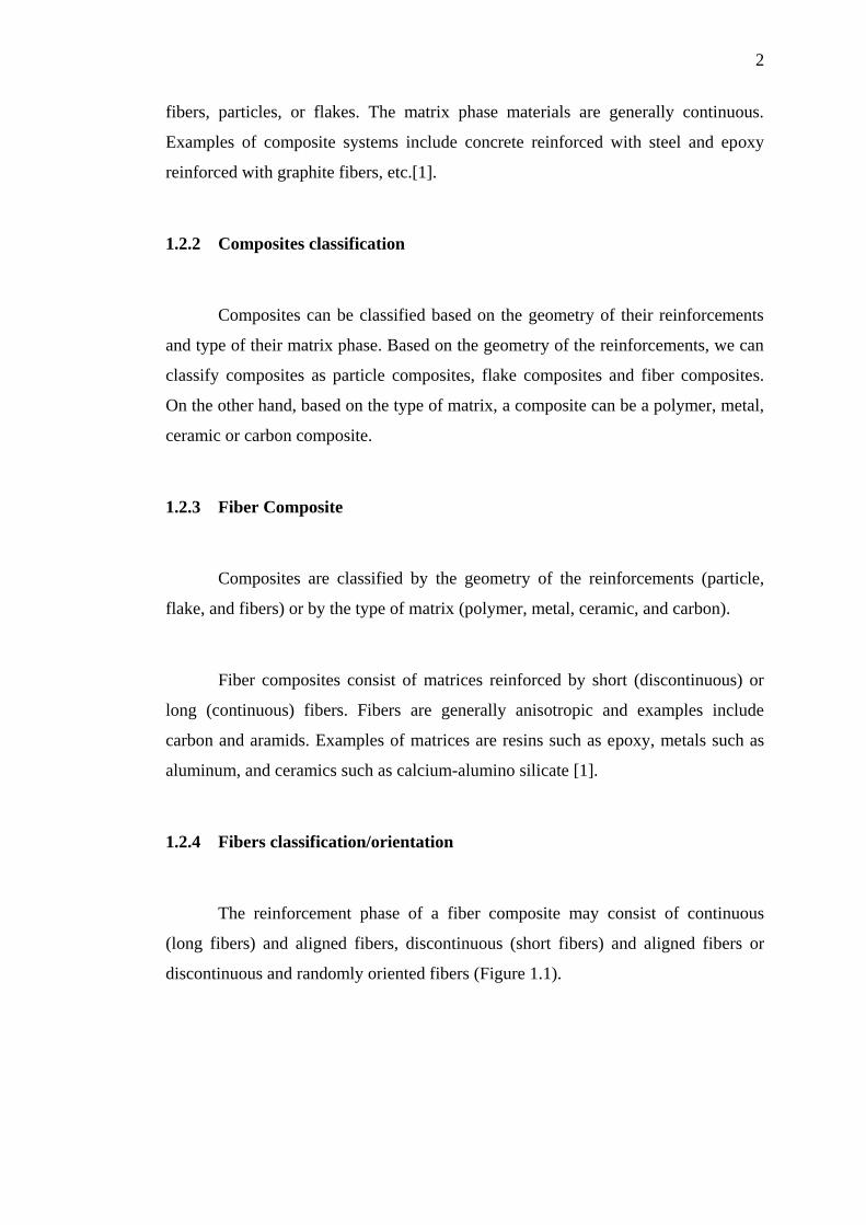
1.2.4 Fibers classification/orientation
The reinforcement phase of a fiber composite may consist of continuous
(long fibers) and aligned fibers, discontinuous (short fibers) and aligned fibers or
discontinuous and randomly oriented fibers (Figure 1.1).
3
Figure 1.1Fibers classification/orientation. (a) continuous (long fiber) and
aligned fibers, (b) discontinuous (short fiber) and aligned fibers and (c)
discontinuous and randomly oriented fibers.
1.2.5 Nanocomposites
Nanocomposites consist of materials that are of the scale of nanometers (10-9
m). Whenever at least one of the constituents of a composite is less than 100 nm, it
can be classified as a nanocomposite. At this scale the properties of the materials are
different from those of the bulk material. Applications of nanocomposites include
packaging applications for the military in which nanocomposite films show
improvement in properties such as elastic modulus and transmission rates for water
vapor, heat distortion, and oxygen[1].
1.2.6 Carbon nanotubes
The modern world desires new technologies which are based on new thoughts
toward science separated into several categories, for example, from medicine to
aerospace. These new technologies require new tools created by novel materials;
these are critical to industry because of some of their outstanding properties. Carbon
nanotubes (CNTs) are a kind of these novel materials in which their applications are
emerging day-to-day. CNTs are molecular-scaled cylindrical hollow structures that
were first discovered by Iijima in 1991 [2]. Lightness, high toughness and strength
are examples of their superior properties. These properties made them popular and
they have been used as reinforcements for polymer, ceramic and metal composites.
4
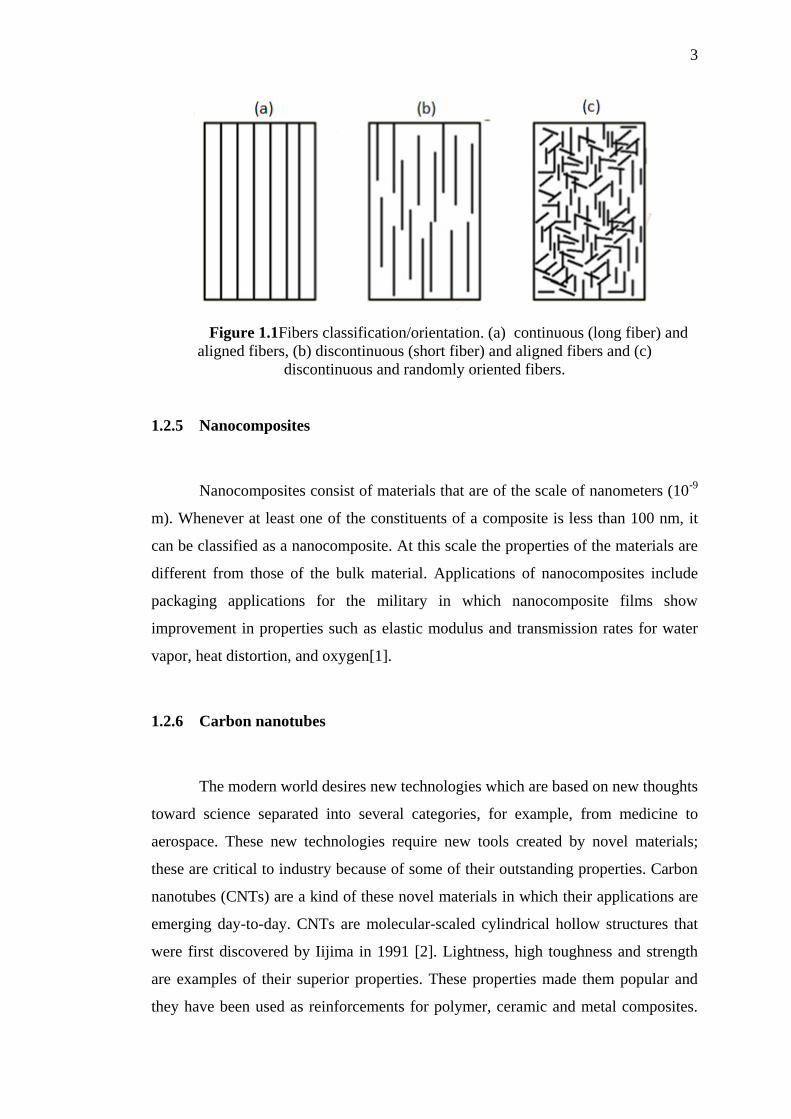
Many researchers have been studying on finding and improving the properties of
CNTs. Most of these studies predict Young’s modulus of about 1TPa and tensile
strengths of up to 63 GPafor CNTs [3].
Figure 1.2 Carbon nanotube(Artwork by futuretimeline.net)
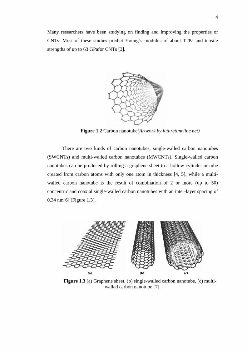
There are two kinds of carbon nanotubes, single-walled carbon nanotubes
(SWCNTs) and multi-walled carbon nanotubes (MWCNTs). Single-walled carbon
nanotubes can be produced by rolling a graphene sheet to a hollow cylinder or tube
created from carbon atoms with only one atom in thickness [4, 5], while a multi-
walled carbon nanotube is the result of combination of 2 or more (up to 50)
concentric and coaxial single-walled carbon nanotubes with an inter-layer spacing of
0.34 nm[6] (Figure 1.3).
Figure 1.3 (a) Graphene sheet, (b) single-walled carbon nanotube, (c) multi-
walled carbon nanotube [7].

5
1.2.7 Representative Volume Element
A representative volume element (RVE) is the smallest material volume
element of the composite which can represent the behavior of the whole composite
sufficiently accurate.
Figure 1.4 Representative Volume Element (RVE)
1.2.8 Volume Fraction
Volume fraction is the total volume of all the fibers within a composite
materialdivided by the total volume of the composite. It can be shown in percentage,
which means the percentage of the volume of fibers distributed in a composite over
the total volume of it.
( )
(1-1)
6
Where, is the volume fraction, is the total volume of the
distributed fibers and is the total composite volume (including the
fibers and the matrix).
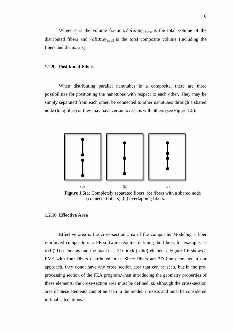
1.2.9 Position of Fibers
When distributing parallel nanotubes in a composite, there are three
possibilities for positioning the nanotubes with respect to each other. They may be
simply separated from each other, be connected to other nanotubes through a shared
node (long fiber) or they may have certain overlaps with others (see Figure 1.5).
Figure 1.5(a) Completely separated fibers, (b) fibers with a shared node
(connected fibers), (c) overlapping fibers.
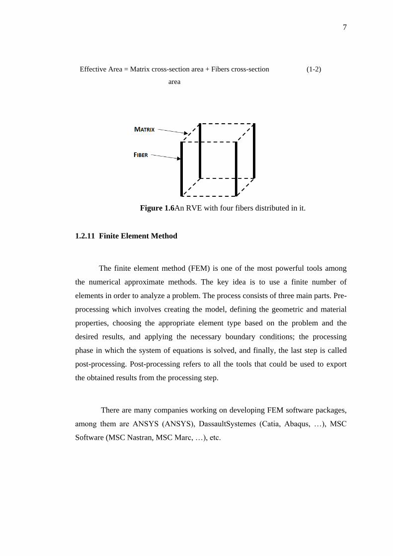
1.2.10 Effective Area
Effective area is the cross-section area of the composite. Modeling a fiber
reinforced composite in a FE software requires defining the fibers, for example, as
rod (2D) elements and the matrix as 3D brick (solid) elements. Figure 1.6 shows a
RVE with four fibers distributed in it. Since fibers are 2D line elements in our
approach, they donot have any cross section area that can be seen, but in the pre-
processing section of the FEA program,when introducing the geometry properties of
these elements, the cross-section area must be defined, so although the cross-section
area of these elements cannot be seen in the model, it exists and must be considered
in final calculations.
7
Effective Area = Matrix cross-section area + Fibers cross-section
area
(1-2)
Figure 1.6An RVE with four fibers distributed in it.
1.2.11 Finite Element Method
The finite element method (FEM) is one of the most powerful tools among
the numerical approximate methods. The key idea is to use a finite number of
elements in order to analyze a problem. The process consists of three main parts. Pre-
processing which involves creating the model, defining the geometric and material
properties, choosing the appropriate element type based on the problem and the
desired results, and applying the necessary boundary conditions; the processing
phase in which the system of equations is solved, and finally, the last step is called
post-processing. Post-processing refers to all the tools that could be used to export
the obtained results from the processing step.
There are many companies working on developing FEM software packages,
among them are ANSYS (ANSYS), DassaultSystemes (Catia, Abaqus, …), MSC
Software (MSC Nastran, MSC Marc, …), etc.

8
1.3 Statement of the Problem
Since the consideration of materials in nano scale is very difficult and time
consuming, using a numerical method (finite element) is required.
The purpose of this study is to simulate the behaviour of composite materials
reinforced with carbon nanotubes in order to find the mechanical properties of them,
such as Young’s modulus and Poisson’s ratio. For this, MSC Marc which is a FEA
software has been used.
Many researches have been done to anticipate the elastic properties of this
kind of composite materials (short fiber reinforced composites). The aim of the
actual research is to continue these works and to offer a more realistic modeling by
considering three different cases of fiber arrangement: completely separated fibers
(as in the previous work), fibers with overlap, and fibers connected through a shared
node (long fibers). This consideration of different fiber positions is much closer to
real distributions and allows a more accurate prediction of the macroscopic
properties of the composite material.
1.4 Objective and Scopes of theStudy
1.4.1 Objective
To determine the mechanical properties of CNT reinforced composites for
different randomness / arrangements of the tubes and volume fractions.
1.4.2 Scopes of the Study
Literature Review of previous studies
Generation of appropriate computational model

9
Simulation of tensile test to predict the Young’s modulus and
Poisson’s ratio of CNT reinforced composites
Evaluation and Documentation
2

51
REFERENCES
1. Kaw, A.K., Mechanics of Composite Materials, Second Edition. 2006: Taylor
& Francis.
2. Iijima, S., Helical microtubules of graphitic carbon. Nature, 1991.
354(6348): p. 56-58.
3. Harris, P.J.F., Carbon nanotube composites. International Materials Reviews,
2004. 49(1): p. 31-43.
4. Zhang, H.W., J.B. Wang, and X. Guo, Predicting the elastic properties of
single-walled carbon nanotubes (vol 53, pg 1929, 2005). Journal of the
Mechanics and Physics of Solids, 2005. 53(12): p. 2794-2794.
5. Rakesh Prabu, T., Finite Element Modeling Of Multiwalled Carbon
Nanotube, 2010, National institute of technology Rourkela.
6. Rahmandoust, M. and A. Öchsner, Influence of Structural Imperfections and
Doping on the Mechanical Properties of Single-Walled Carbon Nanotubes.
Journal of Nano Research, 2009. 6: p. 185-196.
7. Kreupl, F., et al., Carbon nanotubes for interconnect applications. Ieee
International Electron Devices Meeting 2004, Technical Digest, 2004: p. 683-
686.
8. Fukuda, H. and K. Kawata, On Young's modulus of short fibre composites.
Fibre Science and Technology, 1974. 7(3): p. 207-222.

52
9. Tandon, G.P. and G.J. Weng, The effect of aspect ratio of inclusions on the
elastic properties of unidirectionally aligned composites. Polymer
Composites, 1984. 5(4): p. 327-333.
10. Ferrari, M. and G.C. Johnson, Effective elasticities of short-fiber composites
with arbitrary orientation distribution. Mechanics of Materials, 1989. 8(1): p.
67-73.
11. Papathanasiou, T.D., M.S. Ingber, and D.C. Guell, Stiffness enhancement in
aligned, short-fibre composites: A computational and experimental
investigation. Composites Science and Technology, 1995. 54(1): p. 1-9.
12. S. B. Sinnott, O.A.S., C. T. White and D. W. Brenner, Mechanical properties
of nanotubule fibers and composites determined from theoretical calculations
and simulations. Carbon, 1998. 36: p. 1-9.
13. Hsueh, C.-H., Young's modulus of unidirectional discontinuous-fibre
composites. Composites Science and Technology, 2000. 60(14): p. 2671-
2680.
14. Odegard, G.M., et al., Constitutive modeling of nanotube-reinforced polymer
composites. Composites Science and Technology, 2003. 63(11): p. 1671-
1687.
15. Fukuda, H. and Y. Takao, 1.13 - Thermoelastic Properties of Discontinuous
Fiber Composites, in Comprehensive Composite Materials, K. Editors-in-
Chief: Anthony and Z. Carl, Editors. 2000, Pergamon: Oxford. p. 377-401.
16. Thostenson, E.T. and T.W. Chou, On the elastic properties of carbon
nanotube-based composites: modelling and characterization. Journal of
Physics D-Applied Physics, 2003. 36(5): p. 573-582.
17. Chen, Y.J.L.a.X.L., Continuum Models of Carbon Nanotube-Based
Composites Using the Boundary Element Method. Electronic Journal of
Boundary Elements, 2003. 1(2): p. 316-335.

53
18. Liu, Y.J., N. Nishimura, and Y. Otani, Large-scale modeling of carbon-
nanotube composites by a fast multipole boundary element method.
Computational Materials Science, 2005. 34(2): p. 173-187.
19. Eslami Afrooz, I., A. Öchsner, and M. Rahmandoust, Effects of the carbon
nanotube distribution on the macroscopic stiffness of composite materials.
Computational Materials Science, 2012. 51(1): p. 422-429.
20. Help, Getting started, Mathworks MATLAB R2013a.
21. Help. User's guide. Introduction. MSC Marc. 2012.
22. Help. Volume B. Element Library. MSC Marc 2012.