i ------------'--------------=:, - nasa coml)'jt~;rs' and power distribution. part i...
TRANSCRIPT
, l
f
.,;
~
"
~i t "
l-
I I I I I I I I I I I I I I I I I [
I
•
Systems Analysis Of The Space Shuttle
Final Report
April 17, 1974 - April 18, 1975
National Aeronautics and Space Administration
Johnson Space Center - Houston
under
NASA Contract NAS 9 - 13940
Department of Electrical Engineering
NASA CR·
/~/pgZ
(NASA-CR-141887) SYSTEIIS ANALYSIS OF TH2 N75-25997 SPACE SHUTTLE Final Report, 17 Apr. 1974 18 Apr. 1975 (City ColI. of the City Univ. of New York.) 196 p HC $7.00 CSCL 22B UncI as
G3/111 27302
Donald L. Schilling Se Jeung Oh Fred Thau
THE CITY COLLEGE OF
THE CITY UNIVERSITY of NEW YORK
...------------ '--------------=:,
https://ntrs.nasa.gov/search.jsp?R=19750017925 2018-07-02T00:07:26+00:00Z

n a 0 0 0 0 ~
J U
0 0 J J J 0 1
. , --,
Systcms Analysis or Thc Space Shuttle
Final neport '
April 13, 1971 - April 17, Hl75
National Aeronautics and Space Administration
Johnson Spilce Center - Ilol\ston
under
NASA Contract NAS 9 - 13940
Department of Electrical Engineering
Donald L. Schilling Se Jeung Oh Fred Thau
Professors of 'Electrical Engineering; Co- Principal Investigators
i

k , ,
0.
o o f] L
u lJ
o !I 1_
'] ;]
]
Table of CODtDntf> i
Introduction
I. Conunullications System
1. Diglt:tl Processing of Video Signals
2. Entropy Encoding of a Delta Modulator Out)ut for Bandwidth Compression
3. Processsing and Cmversiou of Delta Modulation Encoded Signals
4. A Phase Locked Loop with NonLinear Processor
5. The Measurement of Light Intensity of Computer Generated Pictures
II. CO:inputcr System
1. Teatability Enhancement in Digital System Design
2. Parallelism Exploit:ttion in Parallel Computing Systems
3. An E",:perimento'll Simultaneous Multiprocessor Organization
m. Power Distribution System
1. Simulation Program Description for Space-Shuttle Electric
Power Distribution System
2. Automatic Fault Detection
-;',,""i.-'·· ,
!
I
'I.
'~,~,:l·,> .':", ,
,',',.i .~
1 [I
~ "

eel I i
I ; :1
U lO , j Of
j
i o U
... ,'" 'T~;:;/~~'~~'""'~"""_"':-'-,;w--,,,",,,,,,, .... f'f'~.~~~:.~.~,,.~.,,,,",."", .. ,"',.?"'".,..,.;a ....... e "',f1!"'e"iS"",._,'" """',":'*'''', ,4";~"""'~~1~
li
Inh'orluction
This report c()nsists of three: aspects of the Shuttle Systems Analysis problem:
Conunllnicaiiolls, COml)'Jt~;rs' and Power Distribution. Part I summarizes the
Connmmications research .c1it'ected by Professor D. L. Schilling; Part II '
Stm11l1m.'izes the Computer research directed by Professor S. J. Oh and
P~ui; ill summarizes the research on Power Distribution directed by Professor
F. Thau. e
In addition to the three coprincipal investigators tIlls contract partially
sUPPol'ted Dr. C. B. Park and the following Doctoral students: T.Appelewicz,
C. S. Chuang, E. Feria, R. Lei, J. LoCicero, G. S. Mersten, V. Rao,
N. Scheinberg, D. Ucci, L. Weiss and C. Zeigler.
Several papers, summarizing particular aspects of the research
condlwted under this coni'ract, were presented at conferences, and the
paper, "Video Encoding Using an Adaptive Digital Delta Modulator"by
L. Weiss, I. Paz, and D. L. Schilling has been accepted for publication as a
TcchlllCal paper in the IEEE Transactions on Communications.
/
Ii f j ! i I ; II ,
,1 ! e~
1
I"
I
I I .

,.::..
1.J I •
I. 1. Digital Pl'oceslling of Vj.deo Signals
A. High ~eed Frame to Frame Delta :l\I[odulation
Successive frames of a motion picture contain redundant information. The . .
amount of redundancy depends upon the degree of change in the scene from frame
to frame. We are currently building a high speed delta modulator which encodes
television signals in such a way as to use the frame to frame redundancy of
;motion pictures to reduce the bit rate required to transmit a television signal.
Figure 1 shows the basic el'coding scheme. Each large square represents
a successive ftame of a motion picture. Each dot on a frame represe!lts a
pixel (pictwze element). Note that each pixel has associated with it a Delta
Modulator (lIMOD) that follows the same pixel through successive frames.
Thus the lIMOD in the upper most left hand corner always encodes the pixel
in the upper most left hand corner for every frame.
Bit rate compression is achieved in the following manner. From previous . studies of delta modulators it has been observed that high sampling rates are
. required for a delta modulator to accurately encode rapidly changing Signals
BJld low sampling rates may be used on slowly varying signals. The usual
Illethod of encoding a picture by sampling successive pixels within the same
frame teuults in rapidly changing signals which require a high delta modu!a-
D· tor bit rate (typically. 6 bits per pixel). With the frallle to frame· encoding
techuique of Fig. 1 each delta modulato~· is associated with its own pixel. In
o general the pixel value will chBJl~e slowly from frame to frame, allowing the
delta modulator to accurately encc;>de the slowly chBJlging pixel value at a low o bit rate. Using this scheme motion pictures will be encoded at 1 bit per pixel.
o o
At first thought, hardware implementation of Fig. 1 may seem impossible
Since, at 1 delta modulator per pixel, a typical 20(), 000 pixels/frame 3 MHz
bBJldwidth TV system would have to contain 200, 000 delta modulators each
operating at a 6MHz sampling rate. Fortunately only 1 6MUlI delta modulator
need be used to implement Fig. 1;' however. this Single delta modulator will
] Jlave to contain enough shift rElgister type memory to store BJl entire picture
frame.
1)
•

F.' rt t /'<
t\ ~;'-"
~.;.!.<'. '.
~"i ~.
r·~,· ,
, ,. , ~ "
I
I I I ~
~ ':1
~.
~
~
u a u D
n u r J n a
V"·,-.~··,·~7,,·_q·:;,,,V· "'~"'::-"'::-"''"~:V'~~'.''':'~'i:"''r'''"'~'~' ,,-· .. ·.....,~?7~':',~~-..,,~<'~~'rii :~""' ....... Pj,.; ..,.,.«."'Jl, ... ""'"' ....... ~~'I'yJ;;:;, 4,::,
t The reason that 1 delta modulator can replace all the delta modulators of
Fig •. 1 with no increase in operating speed is simple. If Fig. 1 were imple
mented .as shown all 200, 000 pixels could be encoded, decoded and displayed in
parrillel, but a real time television system requires only one pixel at a time in
serial. The retention time' of the eye and screen give the. appearance of a full
picture. We may take advantage of this by starting a single delta modulator at.
the upper most left hand corner of a frame, let it encode that pixel based upon
its previoUS estimate of the pixel from the previous frame, transmit a bit CEk),
store its new estimate ~) for that pixel, and then repeat the process for the
nel>1; adjacent pixel in the same frame. The delta modulator will continue to
encode, and transmit for each adjacent pixel in turn, until the delta modulator
has been multiplexed through the entire frame (typically 1/30 sec). Then the
delta modulator will return to the first pixel and repeat the process for the next
frame.
Figure 2 shows the hardware implementation of the high speed video delta
modulator. The arithmetic and logic portions are being assembled out of
Schottky TTL devices. The 200,000 bit shift registers will either be assembled
out of 4K dynamic Random Access Memories (RAM's) such as the Intel 2107 or
Intel's new 16K Charge Coup.ed Device (CCD) serial memories. The CCD
devices are superior to the RAM's but the RAM's may have to be used if the
CCD devices cannot be obtained. lithe 4K RAM's are used, spedial multi
plexing and demultiplexing logic will have to be used with them to make the
relatively slow 4K RAM's appear as high speed shift registers. The logic con
figuration for the 4K RAM's converted into shift registers is shown .in. Fig. 3.
The addressing logic (not 'shown) consists of 8 twelve-stage counters counting
the pulses of lines A, B, C, D, A. B, C, and D. Each counter output feeds
the address lines of a 4K RAM.
Construction of the high speed delta modulator without the large shift register
memory is complete. Testing of the delta modulator has just begun.
2)
•
.:J
..

t r ~'-.-
r t
1-:_
"
....•.......... : •.•.. : .. ~ .. , . ~.
r f i , , ~"
;.' ,. r ~ ... ' r---r'
,,' ,.).'r.
~:~, f';", f"
~;
....,.,...,.. _______________ ...,.,-----"""'.=-."-. ;::.~;::.<;~:::"~=~!::'~;::.;::,;'-,~::.-:;:. :;:"=' =~:::-:'=,' ~',.,,_::"'":'_:' .. ,'.::.. .. ,.,..,t<. ,,,~, r,B€) "~'~""',_::,:.j~~ -~lt :;"~~
~.
n -
n U
u o
o
o
B. Computer Proceasor for Color Video Signals
We are assembling a oomputer processor for color video signals. The
processor will enable us to feed color video signals from a color TV camera
into a computer. The computer will be able to process the video signals and
display a picture on a video monito:r.
The basic system is shown in Fig. 4. An image originatinating in a 35
nun slide p)''IlJector is focused on a color TV camera. The TV camera has
three video outputs, one for the red component of the image, one for the green
component of the image, and the third for the blue component of the image.
Each of the three video outputs is put into a scan converter which stores a
single picture frame in its electrostatic storage tube. Upr·n receiving com
mands from the computer the scan converter transfers the stored picture into
the computer. The rate at which the scan converter sends information to the
computer is controlled by the computer. The computer can also randomly
access the information stored in the scan convorter, i. e •• the computer can
read the pici11re elements into its memory in whatever order the computer
program requires. After the computer processes the picture, the picture is
read out of the computer and stored on three scan converters, one for the red
component, one for the green compenent and one for the blue component of the
picture. Again the computer controls the rate and order in which the picture
elements are stored in the scan converter. The scan converters are read out
onto a TV monitor which displays the picture. Since reading of the scan con
verters is nondestructive and occurs at 30 frames per second, the user of the
system sees the picture frame frozen on the TVmonitor. The picture can be
kept frozen for several minutes and then photographed for a permanent record.
When the system described above is completed we will have a verY flexable
research tool. By simply changing computer programs the system can perform
image enhancement, bandwidth compreSSion or any other type of image processing
one·lnight want to perform on color pictures.
3)
•
ij :J .. , .
I' . i I ! , '.,'

J I ~
o H
U o
o o
, . f]
L ,;\-.
I.·]·· i .
n :]
FIG. \.
oil 1100
e. MOO
A MOl)
A MOP
FRAM E TO FRAME ENCODING
.... ----- N PI)( E'LS------+II •
II III , I .~
'1 11 Iii Ij ..... ,< t,~

~ ! ~ !
;,
, t i
:;; I <"
" ,~
,~
'1
I
><
(g
'II-]
'!y'
" 9\ N • :t: -G"I :t: (J')
"'0 m ITi t:7
< -0 ITI 0
I> ~ c 0
•
" -
"'-!t
~ r I\~ ~,
oN L ' I ,~~ "l\-, __ f'
.J:
'i! 11. _
." '" :> '" " -t
.. "' t ::. » ..
III ',>
"'i
~ l> "'i .tIl
.". ."
" ... ., ~ ~,
'" '"I ." 't!
'" -N ",
:a III Gl -'" ~ 11\ :II
seVEN 2 <J<J I<
Sl/IFT (!'fGISTEA.s
'" :z: 't-SN7'toS?,/ Q," F- F • '" I
S,,' 1-00/( BIT
r
'" en
1
StflF'r Illi(;l>rtrAS
I
1
1-1
'" 1-" -., ~
"'
~ r .,
'" > q .., ~ Q
" Jb. ;)
~
"1 I I
,. '" "" ."
rl~ ~ --rlh if-s 18/ -"Ii'-7ft .. ecC,fl/;NT.s-
;l> TfTrT
l-SN7'1SIS7 ~TO 'I s e-L 1ft; r'''-
~~~TT~T:~0~tL~J~'t~
[]
o [l
[I
o o o I: In
f..J~ LJ.
n o u
::i .., l>.
3- SN1'fS7<t,. ~ ~'SN7'tSfffl AAITHMt:TIt: ~ F£(I' F(uP$ ~ ." IUEN/iNTS
I I I I' ;l: I I I I I , ~
n ~'
l III_~ __ . '· TTTU "~~lli L.... rli .' "I
, ~ I gl~ ,tOOI't Sh'l,:'r--~ 200f{ SUIF"( ,.,
-:' ,~
~'~
I > ;~
.~ ;;1
i~ ::41
,"l* ~;'''''i . ~,' ·Y.
;,.J ,- ;.~
-h ,j
.+:;
~ j
-~l 1 'J I 1 ,-J
1 :1 '1
.4
'j l
, '.j" " -·,t , !
t 1 Y.,,,.srEfI SI Z E
"T;t rr ~ -'1 \';
-t." A.c", I Me hi!,' • C... I 1 " .-.-., I . _____ 7:.;;'-':_"'-- __ , '--" -I - - " m o '",'_'
~!:.:o..;B,~ ..... - • .12< 1'fit t" . j'T·n iC 'it' ." <,'..;_'"'-' .. ~ ............ ...l.~ ... ....:~"'_.,_c'_'..k..."";.i,~,_.,~,,'~.~~~:,.J:_~~~ . ..,,_~; __ ~,;,.,.,.~; ",_~_,_" ,< _'-d","_ '. .L-_ ' :"~

rr , •. ;;;; k4 .-•• .w;
-I> q hi R I) ~
4. ~!A ~ A
r---- -p q IJ R I> q
u::- hI!R .. e -
F!G.3. 32 k SHIFT REGISTER ! E ! E , , t-
E ~ .. I···.
."
.~
r ..,
,
~ , , r~
It /( I'1fM F'r F·r
•
6)
1 , j
,
~: n 'rI
-. i: ~ g
r
11 t , c
f-'--~ TO
, n ~' ~.
INPUT i> 1 OIJTPUT
GMS/S - GMI3/S
NUX
--r A I T
,'-~
1.1 "-it' ~ .. '
~", "
!,.' . n ~,
-~. r "
U ,
n il ;--
Ol?l()
C oJ> Po 'llv,
T Dol?
[]
0 -
f· 0 I D I ,
~. ~:-
0 I" f,:
seAlAL-/1.0 r s.P.. INPUT I. .6
GMH.· CLOCK INPUT .,,1 1 r
! " t. 0 fi:'
'fStAGE" SH.fl.eG 3 S,TACe. COU NTER .,
I I I CL
At or C~tti ~'r V _ ABC 0
[1
-",,,'- '",-:;:,.--

i ~.
,.
o o
u []
lJ [J
.1]
:]
:j L
U
LJ
r r1 ~. L
i t .. ,.,
ORIGINAL PAGE IS OF POOR QUALITY
w Q
-J cr,
0 ... v
'" h 0 "':' Q..
o o o o o o
0:: o t--
:<::> 4:::;: 1..10 V1U
z> «Z '-'0 U)v
7)
• tn ...I ~ 2: ~ -v,
0 w Q -> a:: 0 ...J 0 U
. a:: 0 LL..
a:: 0 .."
'" LIJ U 0 a::: 0..
a:: I.!J I-~ ct..
I: 0 u
:t I..!i -u..
~W-~ ••. . •• _ .••.•
~:',4,.· -6 ;f·M:Lj~[;':,;:,~~~,:.;':i..~"';;~~-~.ii'';.L .... ,.,,,'';~~.cl..;t~~.,,L~\b;~~,'ii~,~~~~k~i:=~.;\~,;,.£fi0~;;:~~.';;;;~';';"L .. ,.{~;;"":.1,:,_:.,.';';1b ;:c&~!;).·';:";'';~:;~;L:~',~ ;:;:'"-' ,: __ -" ,:;::!,c_,
,;
1
j 1 , J .~
1 1
j

. ; ,
u u [J
u u f]
!l :J
rJ
U
1
..
I. 2. EntToPY Encoding of a Delta Modulator Output for Bandwidth Compression
A. Abstract
The output bit stream of the Abatp. 'Mode Adaptive Delta Modulator with voice
source input has been studied. It is found that about 50 per cent of the bits are
in a steady state sequence, "1100", when the input voltageil are relatively low.
Hence, the output bit stream can be coded such that the final bit rate and band
width are reduced. Two ldnda of coding tec!miques, the Huffman coding and run
length (loding, have been considered. The Huffman coding is found to be superior
to the run length coding. However, the direct Huffman coding algorithm, which is
an information preserving code, does not result in a high data compression r;ttio.
The modified Huffman coding scheme, an information degrading process, is
currently being studied.
B. Introduction
1. " Historical Background
Source-encoding or data compression techniques are used to reduce the
volume of data generated. As a result, the bandwidth of the channel over which
the data is transmitted is reduced. There are t,vo ldnds of data compression
techniques: information preserving and information degrading. When the in
formation preserving proeess is used for coding, all of the information presented
before'coding can be regenerated. Whel'as, when the information degrading
process is used, only part of the original information can be regenerated. How
ever, for the information degrading prooess, a fidelity criterion can be chosen
such that certain bits of information can be ignored in order to obtain a better
result in data compression and still be able to retain a relatively high intelligi- ,
biU.ty.
Source-encoding systems can be chssilied as either "variable to block" or
"block to variable". A systemaccept1ng a variable-ll'ngth sequence of digits
frOJ;ll the source and generating a fixed-length 1Jlock code word is called a
'variable to block" encoder. A system accepting a fix-length block of digits
8) .
• ~" ~
ri~-:~~::L.i._~"""';';;.~"",",~~C02.C~~~"'"'-~E"~';;.;'';';'''''''-~Jc''i,''~'''''i''''",,;'''A',~,,_.c;"'~~:::==;:" 0" .,o:~.
•
1 ,
j •
i i
I
I 1 1

t-,. i , ,~
.,,'
~ .~~~~~~~~-~-----~-----.., .. \ .........
rt ••
II L
!J
[ I fl U
o
from the source and generating a variable-Icngth block code word is cnlled a
"block to variable" encoder.
A binary memoryless system generating a statisticnlly independent source
alphabet, (0, 1). can be characterized by the probability, P and (J. - p). P is
defined as the probabilit,y of a di!,'it "1" being emitted, and (1 - F, is defined
as the probabilit,y of a digit "0" being emitted. The entTopy of th~' source is
defined as
and is a measure of the information content of the source.
9)
If a binary memoryle!:s digital system has n possible values. (Xl' "2' •••• xn),
to be encoded with the 1"'llballilities, (Pl
, P2
, .... PJ respectively. Then,
the entropy of the source is
n H(P) = - L:
i=1 P.log
2P .•
1 1
For example, xl = 00, x2 = 01, x3 = 10, x4 = 11.
P3 = 1/4, P 4 = 1/2, Then usingEq. (2),
H(P) = 1.75
and P1 = 1/8, P2 = 1/8,
In the allove example, code words are not assigned to single digits but to blocks of
digits. In other words, the encoder waits for the source to produce a block of
two digIts, then asSigns a code word to the two-digit block.
According '.;0 Shalll1on's noiseless coding theorem (1), the minimum average
code-word length is equal to H(p). The theorem is stated as follows: Given a
o random variable, x, in a bi.nary system wi.th entropy H(x) , there exists a code
for x whose average code-word length, 11. satisfies
]
~ !
• I i
I • >t "'.
)
j (2)
. .
~;:~~y-. 'ril::=~~~i:'~=~="'~~~~i'~'~~~i'~i;;<:~~'~~"':E:~'\~h:~"'~~:""i'~ 'i_·~~~.'C'.k_'.· ..... ,'., .•. ,;~ .· ....•.•.•.•. l.~ .. '.' ~

n -
II
[]
o IJ
n 11
I]
[J
o IJ
H(x)::;; n < H (x) + 1.
If a long source sequence of N blocks is the input to an optimal sour'Je
encoder. the output will be a sequence of NH(p) bits. In the previous example,
since each block consists of 2 digits, the total length of the input sequence
is 2N Nts. The output sequence length is 1. :75N bits. The maximmn data
compre&~;'on ratio is, then,
2N C 1.75N = 1.143.
The maximum data compression ratio depends on the statistics of the
encoding source. In other wordS, once the probabilities of occurrance of
the different patterns of the source digits are known, the maximum data
compression ratio is theol,'etically determined.
2. Huffman Coding
The first optimal coding scheme developed was the Huffman coding (2).
Thi,s is a "block to variable" technique. When Huffman coding is applied
to a binary memoryless souroe, the source sequenoe has to be broken up
into blocks of N bits long. Then, each block contains one of M = 2N possible
messages. The least pRobably message is assigned a code word containing
the longest sequence of bits. While the more prolJ!!ble messages are aSSigned
code words of shorter length.
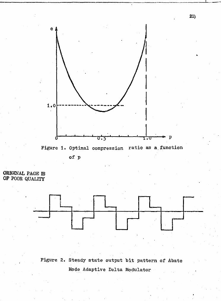
3. Run Length Coding
Rlllliength coding (3, 4) technique is "variabJe to block". It works well
when probabiliw P is either very low or very high. In the case of low
probability P, the namber of consecutive zeros axe counted and transmitted
(l,S a block of binary digits. In the case of high probability' P" the n.umber of
consecutive ones are cOlUlted and transmitted. The optimal compreSSion
ratio as a function of P is shown in Fig. 1.
30)
(3)
•

i::'-
o D
u
o [1 L
IJ
o iJ L
II il :J
C. Theoretical Considerations of Spurce Encoding of an Abate Mode
Adaptive Delta Modulator
For a DC input voltage, the Abate Mode Adaptive Delta Modulator has a
steady state oUput pattern as shown in Fig. 2. It is Imown that during speeches
or telephone conversations, there are many short period of pauses. In the
noiseless case, this pauses will be considered as DC voltage by the delta modu
lator and a stream of steady state pattern will be generated. Also when signal
voltage and signal frequencies are low, the output bit stream of Adaptive Delta
Modulator will be viewed as segments of steady state patterns corrupted by
some noise bits, as shown in Fig. 3.
The length and frequency of the steady state pattern depend upon factors,
such as input signal voltage, minimum. step Size o~ the Adaptive Delta Modula
tor, sampling rate, and signal bandwidth. The run length coding scheme will
be used if the steady state pattern is very long. When the steady state pattern
is not very long but its probability of occurrance out of the entire bit stream is
very high, the Huffman coding scheme should be used.
The steady state pattern is as follows:
•••••• 1100110011001100 •••••• If a block of 4 is chosen for the Ijuffman code, the steady state pattern can be
broken up into four different steady state sequences, 1100, 1001, 0110, and
0011. If a block of 6 is chosen, then the sequence will be 1100ll, 100110,
001100, 011001 •.
In the na:l..1; section, the experimental results will show that blocks of 4
are better than blocks of 6 in the sense that the maximum data compression
ratio is hlgher for blocks of 4. The reason is obviously because the steady
state pattern is a repetition of a 4 bit sequence. Higher bit blocks will
drastically increase the numpar of sequences to be coded thus decreasing
the ratio of steady state sequences to other sequences.
D. SumJ.n,ary of Results
1. Experimental Results
In order to determine whether the run length code or the Huffman codc
ill better for the Abate Mode Adaptivc Delta Mo!iluL.'1tol', we muSt know how
11)
•
.. ,
I

n .,.
o o []
[]
o f] l.
u :J
:]
long a run of the steady state pattern is. The average run length of the steady
state pattern for this experiment was calculated using a PDP-8 computer.
Figure 4 shows the procedure employed to obtain this statistics. Since it
is desired to have the computer simulated Adaptive Delta Modulator worlt
in real time, the sampling frequency is, therefore, determined by the length
of the computer program. In other words, after each sample value have
been transferred to the computer from the A/D converter, the computer
will go through the program's process of generation the output bit and
analyzing the statistics before it goes back to take another sample. Since
the PDP-8 $ not a high speed computer, the fastest sampling rate we can
manage to obtain is about 5KHz. However, a sampling rate of 32K is
standard for Delta Modulators. Therefore, a process of slowing down
the speed af the source tape is necessary. By alternatively playing back
and recording at different speed with two high quality. Ampex tape recorder,
a voice tape af 1/8th of the normal speed was successfully made. This
l/Sth speed voice tape was originally part of a magnetic open reel tape
recerded by the Ampex Company with Ed Begley reading the story of
Mark Twain •. This tape was used as the voice source for all the experi
ments in this report.
All of the programs are written in proper length such that the sampling
rate of 4KHz becomes equivalent to 32KHz at normal speed. The digital h
estimated Signal, x (k), of the simulated Adaptive Delta Modulator was. first . h
fed into a D/A converter; then the analog estimated signal x(t) was generated
and recarded into a tape recorder. This magnetic tape then weut through
the reverse process of slowing dOWll, preViously described, to return it
to the normal speed. Finally, this tape's intelligibilitywl'ls determined by A
playing it back from a recorder. While the estimated signal x(t) was being
recorded, the computer was doing statistical computations and storing the
results in its memory. The results are compiled for a total of 20 minutes, a
time interval which we believe is long enough to collect unbiased statistics.
The average run length of the steady state pattern is listed in Table 1.
l,' i] 1
····.·1.:
,-
.~
n i·
·,······ , [ ".~
I~· ... , ....•.. : ..... . 'I i- ':'.
·--t--~= :.' ." -'.' .::",-

,,"
o o
Note that the average run length is not very long. A run of 2 or 3 is definitely
too short for a run length code; .therefore, the use of a run length code is
ruled out.
The output bit sequen('e of the Adaptive Delta Modulator is intrinsi-
caly dependent on the slope of the input signal. Increasing the minimum
step size, SO' will haVI;l the same effect as decreaSing the input signal level.
The following factors were chosen to perform the experinient:
(1) Voice signals are bandlimited to within the range of 300 Hz to 2. 5KHz.
(2) Sampling frequency f , j.s adjusted to 32Idtz. Some other different . s sampling frequencies are also used for comparison purpose.
(3) The minimum step Size, So is set to be 40 my,
(4) The maximum peale to peak input voltage level is varied in steps from
1v to20v • p-p p-p .
In order to apply the Huffman coding technique to the 0 uiput bit" stream
of the Adaptive Delta Modulator. a computer program is written to search
for the steady State sequences. When blocks of 4 hits are used to form the
code word, the '1100' sequence was being searched for from the entire out
put bit stream. Whereas, when bloeks of 6 bits are used as in the Huffman
coding block, the '110011' sequence was being searched for •. The results
are shown in Table 2 and Table 3respeciively. It is clear that blacks of
4 are better for coding than blocks of 6, and low input voltage level have
shorter= average code word length. It is also found that in the case of
fs == 32KHz, So == 40 mv, the input voltage level of 2 volts peak-to-peak
or higher results in very high intellegibility. An input voltage level of 1
volt pealc .. to"'peak or lower results in poor performance due to utrfiltered
in-band granular noise.
By referring to Table 2, it can be seen that at 2 v P""P input" signal level,
53 percent of the total bit stream lJ.re inthe stelJ.dy state sequence and yet,
we siill maintain high illtelligibility. These results encourage us to do
further studies on the probability distributions of 16 different sequences.
TIns data is listed in Table 4. In order to give a better visual comp!lrison,
i, II
1.···.··.·1 !J ~~;;:=.-... ,.-,l-.. .. -... -..... ,,-... -.. ,-...... -.. -.... -.. , .......... >--:" ......• -. --.. - .. -•.. - ...... -••• -•.•. -. - •• -••• - .. -.-•.•• -. --•••
. 13)
•
.'

o u o o o o IJ
o n Ll
o o o
they are plotted in Fig. 5 through Fig. 9. From Fig. 5 and Fig. 6, it can
be seen that the probability of occurrance of steady state sequences (0011,
0110, 1001, 1100) are much higher than the others. This fulfills the
ftmdamental requirements of the Huffman coding scheme. It also CWl be
seen, by referring to Fig. 7 Wld Fig. 8, that the probability of the steady
state sequences are not exceedingly higher than the others when the'inprl;
voltage level is increased. In the e:l.ireme case of 20 V ,as shown in p-p Fig. 9, the probability of steady state sequences are even, less thWl some
other sequences. Hence, a number of general conclusions CWl be drawn
from these results:
(1) Blocks of 4 should be used to construct the HuffmWl code.
(2) As far as signal to lloise ratio is concerned, the performWlce of the
Delta Modulator is very good when the input voltage is 2 V or higher. p-p (3) At low input voltage, the resulting probability distributions are most
suitable for coding.
(4) From statements (2) Wld (3) above, it is clear that the probability . distribution for 2 V input voltage, as referred to in Fig. 6, should p-p be used for the coding scheme.
2. Information Preserving Coding
The entFopy of the coding source is a measure of the information content
of the source ami is the lower bcmnd ·of the code word length. Table 5 shows
the entropy of the source at different input voltages. It was found that at an
input voi:tage of 2 V the minimum obtainable code word length is 3. 56, p-p
which gives very little data compression. The actual code word length com-
puted aftet' the code has been constructed, as shown in Fig 10, is 3.598. The
data compression ratio is 4/3.598 = 1.112, which is certainly not satisfactory.
The reasons are twofold:
(1) The four most probably steady state sequences are coded separately,
consequently, three digits are needed toeode each sequence. However,
if these 4 most probably seqUences clm be represented by one sequence
with the probability 4 times higher. then a single digit is enough to code'
this sequence and a tremendous savings in code word length can be e"-'Pected.
(2) As it CWl he seen from Fig. 6 and Fig. 10. the probabilities of sequences,
• • .W , ..... 4\ -, ,JfP:.flpg:q",;;,. : •. --.. ', '--j
14)
•
j
ii' j • , OJ
Ij
1
1 1 1 i j

f ~ t
~t .. ; .......••..••. ' -
','
'"
[ t ' l ! f' ~, '
~;; ~'"
t! 'f-
!(.:
o u
lJ I 'I t."
'1 \J
[J
Ll
!l
'0000', '1111', 'OWl', and '1010' lire much lower than the other sequences.
Thus, they can be neglected without significantly degrading the performance.
The 6 digit code word will not exist if these 4 sequences are neglected. There
fore, a further shortening in code word length can be again expected.
3. Information Degrading Coding
The probability of occurrence of the "0000" sequences is very low as shown
in Fig. 6. The encoder can be designed to receive this sequence and to send
out the more probable sequence, "0100". Similarly, the "1111", "1010" and
"0101" sequences can be converted into the ,il 011" or "DIDO" sequences as shown
in Fig. 11. Fufhermolle, if a sliding block coding algorithm is used, there would
be only one steady state sequence "1100", with probability higher than 50%. If
we assume that the 4 steady state sequences could be repr.,sented by one sequence,
the final total number of sequences to be coded would then be reduced to 9. The
average code word length would thus be reduc'ed to 2.228, as shown 'ill Fig. n. The performance of this information degTading process is not yet determined.
The complete algorithm descrimillg this process is currently being researched.
However, the theoretically computed value, 2.228, gives us some valuable in
dications that the coding of the Delta Modulator for bandwidth 'compression is
feasible.
E • .9.Q£!_Cl~~
A thorough study of the statistics of the output bit stream of the Abate Mode
Adaptive Delta Modulator has been parformed. A few conclusiollS ean be drawn;
they are stated as follows:
(1) The "block-ro-variable" coding scheme should be used for the Adaptive Delta
Modulator. The optimum block length is four bits.
(2) The cli..rect Huffman coding technique does not ~'esult ill a high data compression
ratio. Hence, a modified information-nonpreserving coding seheme based on
the Huffman method should be derived to meet the theoretieal bound.
, 15)
•
----------------------.. -,~----------------~----'-----
! ,
I

r'."·" . ., .. ; . .J,J_ ...... ________ .;;..;...:.::.::..-.:.::--::..--,:.:~c='-·=----':.:::·"=:c ::' "=' =.---'=.-~=.-=~'-=--=~-=. '-::::--::::"-::::. ::::"-=~'='V-='~=.~.=. .::::. ='-~=-=~=' ='=-=~=--~':" =-:,:,-,=~·""",~",,,"-.t""'J"'·:-:= "I "i .,
~ 1 p ~ I
t l' 16)1 ~. ~E Further studies are still to be done in this area. Some theoretical cal-l
. " ~I cuIations for the information degrading scheme is needed. Transfol'mation'l
n o o o o o o o []
U
I J
11
methods, such as, Fourier transformation, Hadamard transformation,
Karhunen-Loeve transformation, and others, are alternate approaches to
reduce the final output bit rate and chrumelbandwidth. The video signal
source using tile Song Video Mode Adaptive Delta Modulator has not· been
analized at the time this report is written. Further expansion from an
audio source to a video source is the next plrumed reSearch.
(' I !U
~:~,c.-" .. , ...... :h-_ '," ,_-.... .-->.-,.,-... ,-' .. -. -...• ,-·,c.-' -~.
• 1 )
e! 1 '1
.. :~
·1 -;~
J <-41 ]
,1
1 1 ]
~ .~
I ]
ii' ':.'

r-~
! , L
f-~
~' ' :< '
~,' i t·' • " J,
" it;:, r:" E. '" r [-.
f? ,,"-
" p. r:' f'f.
t':.'· t,;'· -,:"
~t/' t.'-\-. :"'\" 1,.
~, ".
~' , 1'-"
, , t'
I • ~
0 u 0 0 U
U
0 0 0 0 Ll I]
:1
II U
LI o
~-" ~:,~,C""~'>! i
References
(1) C: E. Shannon and W. Weaver, "The Mathematical Theory of Communication"
University of Ulinois Press, Urbana, 1949.
(2) Robert Ash, ''Information The01>y" Interscience publishers, 1965.
(3). H.Meyr • H. G. Rosdolsky and T. T. Huang "Optimum Run Length Codes"
IEEE T~ransactions on Commullications, Vol. COM-22, No.6, pp 826-835,
JUne 1974.
(4) J. Pieter M. Schalkwijk "All Algorithm for Source Coding" IEEE 'l'ransactions
o.n Infol'mation Theory, Vol, IT-18, No.3 pp 395-399, May 1972.
17)
•
, . , -r-
, :1.:::,-,-.,-_-,
I
'I I
I i
I I I
I

o o G
o
I I] I i, I '. · .. l i i I II ; I
.![nhJe ]
Average Number of Runs of steady state Sequences at Different Input Voltages
Sequences
1 V p-p
0011 4.81
0110 4.13
1001 2.19
11.00 2.56
Averge: 3.42
Table 2
Input Voltages
2V 3V 4V p-p p-p p-p
2.96
2.25
1.94
2.21
2.34
1.91
2.24
1.86
2.36
2.09
1.86
1.73
1.65
1.97 .
1.80
6V p-p
1.69
1.1?3
1.50
1.74
1.62
The Number of "1100" Sequences Encountered by Shifting Along the
Adaptive Delta Modulator OUtput ]lit stream (In Unites of Ten Thousands
Of Bits)
Input Voltages
IV 2V 3V 4V 6V p-p p-p p-p p-p p-p
Number of
"1100" 89 66 55 50 41
Sequence
Total
Number 500 500 ·500 500 500
Of Bits
Ratio of Bits
in "1100" 710/0 530/0 440/0 400/0 330/0
Sequence to.
The Total
Number of Bits
18)
•
..

Table 3 o The Number of "110011" Sequence Being Searched (Blocks of 6)
I.·.·~.··.·· .
r
[; / .. '
o o o
u o o
I i.·.· j .. I
u IJ I
i j
lJ '.
!\" /:
i~, ' j
Number of
1V p-p
"110011" 40
Sequence
Total Num- 500 ber of bits
Ratio of Bits
in "110011"
. Sequence to 480/0
The Total
Number of Bits
Input Voltages
2V 3V p-p p-p
27' 22
500 500
320/0 26'}'o
4V p-p
20
500
24% .
6V p-p
16
500
19'}'o
19)
~. .
~.l\;;;~;"~:·;~,-",,"'C,,,,-Y'~-' ;;;;.-;,-; .. ::: .. :;-. __ ,-; •..•... ;,.,e' ;,;;."·:s ••• ;;:;.;,~,.,-;;" ... :.,,.~,.:;*;;:7;::;-:::;:;G7C~~::;;::::;:::3Z0i;'2:):;;·.~ i.":,i·:;;:C:.'c·
•
i
I 1 1 j l
l i 1 , 1 1

r""', ~. " .' ,
l . r ( C
":'
;" "
I [ ~ .. i h c i 1---,-" ~.
f':. ~ ,. , r ; ~, '-
~,~f' ~,., -
~t' ~r:'-t ' ~""
~' 11' ~'. t·'," . , '.
L
L ,.
U II i,i
il a 0 0 rJ
0 [J
lJ
0 1\ ·L
f] L
11
[J
IJ
L! [J
-"'~~--"'~' > ~,,,,",":,.,--:., __ :.: ..... ~",;r',,"_.~"""'~~~''''~~~ !. n'~ ... \14). _ ·W '1\,4(4 • •
Table 4
Probabilities of 16 Possible Sequences at Different Input Voltages
Input Voltages
Sequences 1V 2V 3V 4V 6V ; I) 'V u. _ p-p p-p p-p p-p p-p P""P
0000 0.006 0.020 0.022 0.028 0.033 0.035
0001 0.035 0.050 0.033 0.037 0.040 0.070
0010 0.018 0.042 0.077 0.081 0.080 0.088
0011 0.245 0.162 0.092 0.090 0.080 0.053
0100 0.047 0.068 0.048 0.050 0.054 0.105
0101 0.004 0.011 0.018 0.022 0.027 0.018
0110 0.243 0.158 0.143 0.128 0.111 0.088
0111 0.008 0.024 0.064 0.066 0.065 0.035
1000 0.008 0.022 0.064 0.061 0.084 0.053
1001 0.133 0.132 0.118 0.105 0.100 0.088
1010 0.004 0.011 0.018 0.024 J.027 0.018
1011 0.063 0.072 0.050 0.055 0.058 0.105
1100 0.125 0.116 0.114 0.103 0.088 0.053
1101 0.020 0.044 0.083 0.083 0.081 0.088
1110 0.037 0.050 0.037 0.039 0.042 0.070
1111 0.004 0.018 0.020 0.026 0.031 0.035
Table 5
Entropies· of the Output Bit stream of This Abate Mode Adaptive Delta
Modulator When Blocks of 4 Are being Used For Coding
. Input Voltages
IV 2V 3V 4V 6V p-p p-p p-p p-p p-p
Entropy
I@(jJ I~~
20} ,
"~
•
•
' .. ', .l-, -~.;
~ ~~
f,
I ': ~ ~,
r; t:'-',
kt ~rt,
~' ~.
f· [\
E
,
I
0 0 IJ
Ll
LI
: 1
,I
,I
Ll
[1
o
c
o •
Figure 1. Optimal compression
ORIGINAL PAGE IS OF POOR QUALITY
of p
• p
ratio as a function
Figure 2. Steady state output bit pattern of Abate
Mode Adaptive Delta Modulator
, . ''''''''''1'''''''' ' .'" -""",,,"'\:':1 1
'1: ~'1)
21)
•

~.j;
,
i.'-{
-Jla
, )!
k ~,
i'l
I'~I
,---
, ~~
"~'"
::
'::
~=".
.j ~
1 __
-L
-C
'--
r-!
[ I
1-'
[j
['
i r-
'~~;
r
~"
c::
! J
t::::;;;
1 ~
"'=
1
Fig
ure
J.
Whe
n si
gn
al
vo
ltag
e a
nd
fre
qu
en
cie
s are
lo
w,
the A
bat
e M
ode
Ad
apti
ve
Delt
a M
od
ula
tor
resp
on
ds
wit
h s
egm
ents
o
f st
ead
y s
tate
patt
ern
s.
,
• N
~
1Il . .,!!I!I.,
i "r
'" '"
. ~
_ . rp
g;;.;
'i'*
¥M'j
;;
g lL
ndl£
"u!N
" £
22
:z
_J
"""<
"""
L , j , , j I 1 1 j ~
, '1 1
I j'
I " L

f"""""
Y~'~:>
"-'~
" '", "',C'
"0
C
"""
,*,"
,,!,
",'
"'"
T"
"'T'
''''
''''
'''~
''''
"~'~
"''l
r:.
J _
_ i
I=::
J j-
---'
!-,
...
CJ
CJ
I::=
J
;
c:J
r::
:=J
' ;--
; r::
::::J
r ! ~
r:=
I ~
r~1
..=", ~ b
r::::
:J
~; I ~""": .. ;" •••• " .. ' .. " :!', :,,::
, . ~:' 1;,'
1;"1,"
I". >: :J;
,,~ ;,' '. ),.,
IPD
P-B
Com
pute
r v
oic
e . S
low
ing
Dow
n To
S
imu
late
d
Tap
e . I
th
1
BN
orm
al
Spe
ed
.I\.
~t
Ad
apti
ve
DlVI
X'c
.t)
Lis
ten
•
Am
plif
ier-
1-
Sp
eed
ing
t:Jp
To
Tap
e N
orm
al S
peed
R
ecod
er
-_
. -
Fig
ure
4.
Blo
ck d
iagr
am o
f ex
peri
mel
'lta
l p
roce
du
re
Pri
nti
ng
Out
!
Sta
tist
ics
, I
•
I .:l
,'-~ '1 j I 1 j J, 1 ,
~.
'" l
S5
I 1
L:::;:
=:;:::
:;;:;;
;:;:;;
;::::'
:::":;
:;:;:'
;=":::
"~?:::
=::~':
:::,~-
'-,.~ -
::;7;0.
tr ·l¥
&
.. ;~",
,,,.;,
,,,,::
::::L~
"~'d~'
L
.
j,

~,:;
~. ,:f
I;
o o U 'I
l··]
~ 1.·.·1 " L
. .

~~"(.:::,_-:,_.:_ ?'~~"_".~;~':"-_W:'<:;~~~:~::'!:~:;,,\ 7'
-:;"':
\7.:'?
?,",·o
ct-"
"::: .~
'~':n:
·.-
~JF
~--
----,~--------,-.-----
-···
.~t1
\::v
~~;~
·.O.
: ~;~
~:-:.-
,~~: "
"":,.
T';
l':"::;
n::.:-:
·'··
'"7:
;-"7
~r:~
--··
:~:_--';"\"'~~~~?r~~pJ"~,~:-<-~!~~'?'
. ~
J I
---I
L
-J
--~
L-J
'--J
[-]
i .)
[=
:J
[ I
• -(-
6:'
c:
:=J
I I
!:=
:i
r··
I t=
:l
P
r .
r !;'.
: r
,
0.1
Jr l- I-
~:-'
~; l- I-
0.1
~I- ,
;~-'.' J
f 0
,0
.~ !
", vv
V
V:L
V
V.c
v·v
V
'UV
,.
I. '''''.
.L
".I
. v.
"'."7 v
u
• .L
.L.L
':'.
S
equ
ence
s 00
01
0011
·1
10
1
1111
01
01
0111
10
01
1011
Fig
ure
6
. P
rob
ab
ilit
y d
istr
ibll
tio
ns
of
sen
,uen
ces
wit
h V
. =
2 V
.. '
... ~n
p-p
f=3
2 K
Hz.
S
=40
mV
. s
0 t>
.)
• .S
!
~ $#:*:~:2~=;:;;'.~~~::,=t:::::=~J~~:;~':~;~:-_-~=. ;
~~·~-~
:~_;~~
d-ii'~
~~:~_-
-n't.t
~d~:~~
~k'~-~
;:i,::
==;:r:
:~,~,~
~' ',--.,
;'-,::7=
:=~i::-~
'::~~~~'
"-~~:':'
--:::':~
':~~~~~
~>~

~~;.:':::
"'_~
\;?l
'-;:
~' '
F':"',~."_~:;I~"_~--:-to!>~"<'-";;:';-~··
",;;:--
-:,,'''''-
-;'',:--
,'
f;;'-t
-', _
__
__
_
/:
I l
1,1 .. ~"
f
I,', I
" I
_I _~
P 0"1
0.10~ .~
(h05~
f"
. -'::-?::::.T'l?_~~0';T}·~Jt:r::;
~-:-,-
-""~'-
:';"·"
--,"~'
1~':-;:_"::r:~:-"~"T'+~~~~;?,~, :
"f#"
>l~\
~:\,
>,,~
·~·'
lIMi
.~i
,,~f!'
.ift!f
.I'(,
1,-\\
'-"
,_ ":f"fr;-Cr-~-:-r.-~~T;"
~~----.-----'-"---'--'-------~------~-'---~
:----
---,
'---
---'
I
c::::
:; c:
:::
c::::
J c:
:::
I
c::::
--
----
.;
[ ::::
c:::
:J
c::::
::J
I
. I
I:IU
UU
-_.
UU
I U
UI-
UU
U
ll U
--
1 U
UU
1 \lITU~---:rrClv
~~.L V
0001
00
11
0101
01
11
10
01
1
01
1'
11
01
1
11
1
r-::
l t:
=l
. t.
-,
f--1 Ij , '1 Ii I.! 1 IJ ,1 j I 1
Aeq
uenc
es
Fig
ur.
e 7.
P
rob
ab
ilit
y d
istr
ibu
tio
ns
of
seq1
:tenc
es w
ith
V.
=3 v
. p
' 1
n
p-
'I
:" i I
, fs
=3
2 K
Hz,
s
=40
mY.
o
• ~
.$
I L ... "'1'l:.
oi k
,,,';,
'i" ,
."'''
' ...
.. ' ,,
,"'w
,,~~ .. ,. "
"";''
'':;;
:'' h
i;:,:
;:;:
;. L::.
;;:~ ·,:-2
,;:;
:::;
;·;)
' ,,-~

~W;l
lr
.:f\t-
-:-!';,
o _
__
__
__
__
__
_ .
c,'·
F~'·
::'_
·'''
·''·
-·''
,';'
:l~'
--~'_',";;~,',
"';"
,c"'
,J"
, '-.I',
. .:T
' . "'
~T~'
;"; :::r..-.,?,!!·-~i'!;'.{~:'7~~:~' ';:
;-,-'
~. ;:
(~:-
.;::
':T~
r,:,
:-"~
?ry
1~~"
'i"~
?"'~
'~:'
'f~'
';'?
!''7
'-:-
~'''
~''?
~~r'
"",:
~-~~
''1\
;~_'
'''i
-'''
--:'
''":
!''-
'-''
''."
,
1';
I
.... J ' .... I
T, f;, ;;: ;,-,
!".
L..
....
; -'
--'
,---
:---
---,
r=
::1
· r=
::I
[. ]
c'
I '
: q
[ ,
p
~ I 0.
1:0
0.0
5 ,
VV
UU
IO
IUJ.
V
VJ
UV
V
J . .L
V
~
"v
v
J.":
LV
J.,
Vv
J.
J..L
V
0001
O
Oil
0101
01
11
10
01
1
01
1
11
01
1
11
1 i
I r::
::::.l
t::
::;;:1
t=
:J
Seq
uen
ces
, 'j :] l 'J j 1 I ! l
Fig
ure
8
. P
rob
ab
ilit
y d
istr
ibu
tio
ns
of
seq
uen
ces
wit
h V
in=
6 V
p_
p'
f =
32
KH
z,
S
=
40
mV
.
1 '0
.'; ~
~",,
,,";;,,,,,
,",,
,,,,
.~--
-~,-~---. -
~.-~
.. --~-
-.-~
__
__
_ ~'
-m:-
----
~-->
-~.=
.-~.
,.-"
.. ,.~*
~J lin
n;);
wt
;''2
t'
·t*ti
rf't
\t st
It'
'j!
"·I~~'
i!l~~l
b"""~~
"",""'
-"''''
''~'''
-Wl:.i
il.-''
~K "''i
....
....
....
. ''"~'"'''~~~'''''''-''''--=~..i.d~.l~_ .......
,~_,.~''
'''' ...... ~
. __
'-'
'"_~_
'-~~ ,'
_0
:j

~~F'_
.....
,,~-' "-
'>1-
'7--
;-:-;-
,:·_~-
~('.,,
:,rt~.
:i':_~
~JI~'\
~';:---
-~~:
r:F~
-'··
-,.~
;";~
T,~:
r:T'
?1~~
!If'
I'~~
~;j'
-~~0
~'''
'":~
~~~'
~~~'
":";
:,
c::
J r
-J r=
:J
r--
L..
....
J c:
::::J
~;' i:: ,.! " ~{
r--;
I'"~--i
-'--
' L
-.;
p
0.1.
0
0.0
5
.
- . . - ~
~
,'--
--.,
-j
,---
-~
["
~ !
i-')
c ,~ ~
[ I
UU
JU
UU
.U
UJU
U
Ull
u
~'UU
~II~U
l.U
U
IUO
00
01
0011
01
01
all
1
10
01
10
11
11
01
11
11
Fig
ure
9.
Pro
bab
ilit
y d
istr
ibu
tio
ns
of
seq
uen
ces
wit
h V
,. =
20 V
p p
' :L
n -
f =
32 K
Hz,
S =
40 m
V.
s 0
r I
t;;..;
;;;J
.
Seq
uen
ces
• ~ 'j ~ i '~ , 1 \ 1 j I , ~! J " ,jll . Ii 1 11 j r I ,i i -j I
. ~ U
l~
ili
~.~~;~
:::=;:
::::=-
+=;~:;
;:;-::
:=":.:
:;,,:~
.=§··'
~,'~:,
:;"':1
~-~-'-
"-'--"
------
"' __ -' __
'-_'--:::
'",""=.
:::=::.
'''::,~::,:;
":'" ~ j

K ~ ~, :
: l,.
0 ;l..c'
"
~; l';
0 , [. 0 " i" ,~,
~: .
[J r-J L
.','. I II ; I : ', .•.. i '-I r,: . ·r ..
II o o 0'
~.",.".,."~"""",,.,..,...~-. '1"1':=:-• ...,.. •.. . "" .. '","" .. ¥b~ . .,.M_,. ' ...... '''''; ,..,.,> 11114&". n .~ .. """""'P'""·,,,·,,,,~=,,"",,,,_,---p,.,.·c"-,,,. '.,." ........ ", .. ,"." '. . ",., , = . ~
----'--- "!
0011 0110 1001 1100 1011 0100 1110 0001 1101 0010 0111 1000 0000 1111 1010 III 01
.
0 1
0.162 0.158 0.132 0.116 0.072 0.068 0.050 0.050 0.044 0.042 0.024 0.022 0.020 O.Oit! 0.011 0.011
--jJ
---@
-
o
~ 0.3;00
1
0
0.140 0
1
. O. 886 0
V.UO~
11
0.038 0 '1 0.044
0.022
0
0 1 0.272
1
~
J1 0 J 1
v.u:'I4 0
Figure 10(a). Constructing the Huffman code
0011: 000 01l D: 001 1001: 011 1100: 100 1011: 0100 0100: 0101 3.110: 1011 0001: 1100
1101: 1110 0010: 1111 0111: 10100 1000: 11010 0000: 101010 1111: 101011 1011: 110110 0101: 110111
Figure 10\b). The code words
29)
u • .,,,'"
0
0.228 0 1.000
1
0.408 1
; 0.180
"
The average code word length. N=3)t(0.162+O.158+0.132+O.116) + 4 X (
0.072+0.068+0.050+0.050+0.044+0.042) + 5 X(O. 024+0. 02:;!) + 6 X(O. 020+0. 018+
0.011+0.011) = 3.598
•
I .'
ijl 11 Ii ,1 "~
IJ IJ I;, IJ
! ).1',.' j .•. ,
!
I I
I

, ,
~::-"-
il n II H
I n a n [I
o o n []
o o o fJ
30) ,
Received Sequence 0000 0101 1010 1111
Output Sequence 0100 0100 1011 1011
Figure l1(a). Converting the least probable sequences to more
probable sequences
1100 1011 0100 1110 0001 1101 0010 0111 1000
0.568 0.101 0.099 0.050 0.050 0.044 0.042 0.024 0.022
0 1 0.086
'0 - ...
1
1 0
1
0 0• 136 0.096
0 0.040
Figure l1(b). Construeting the Huffman code
1100: 0 1011; 101 0100g 110 1110: 1001 0001: 1111
Figure l1(c). The code wordS
1101: 10100 0010: 10101 0111: 11100 1000: 11101
o 0.23~ 0
0.4::S~
1 1
0.195 '
IV
1 1.00
The average code word length, N = 1xO. 568 + 3x( O. 0 91'1 + 0.101 ) + 4x
(0.050 + 0.050)+ 5x( 0.044 + 0.042 + 0.024 + 0.022) = 2.228
o
~
i J 1] ~~,:0>!f.,~~_:-:,-:r~:.~--------
}
: ~ .'1
, ,
~ :1
•
" " ,

~.,
~,:
;~; ,-,', 0-~ t i~: , v:
~. It,-, .~ .' [~ -~,,' ,.
o o Ll
lJ
LI
U U II
I. 3. Processing and Conversion of Pelta lVIodulation Encoded Sig-nuls
A. Performance of a Pigital Adaptive Pelta lVIodulator
1. Introduction
The most general form of a digital Pelta lVIodulator (PIli) is depicted in Fig. 1.
Here we have assumed that the input sjgnul, x(t), is bandlimited to f and is . m sampled well rulove the Nyquist rate, i. e •• ft:;» 2f
m• A general :l1lathematical
deSCription of a digital PlVI is given by the following set of equations:
and
where
e (Ie) = sgn [I; (k) J • x . x
A I; .. ~,) = x~,) - x ~) x
A A x (k) = x~-1) + S ~,), x
Sx ~) = step size at the kth interval.
The particular type of PlVI is specified by the step size algorithm used to formulate
S (It) •. We shall be cancerned with the Song Algorithm (1) that ~s used with audio x
signals. For this type of adaptive PlVI the step size increases linearlYE:nd 1.s
given by: ,
S ~) '" I S ~-1) I e (k .... l) + S e ~-}). \ x x x X I
where
S '" magnitude of the minimum step Size.
k;;~ ........ ~ .....•...•... _ ... --c-;...----,--,c-.,.--,--,-,-...,.-' ~, .. ; .... J. ". ..... "." ..... ,.'--" .. ,.-;. -
31)
•
(la)
(lb)
(~c)
,
J , ., J , " J ., i 1 "
1 j ~
:.i ,

,"'-
;,.
o u u u o u o o u
ij
-!
" I . ,
In order to evaluate the performance of the Song audio mode DM, we shall
let x (t) be a sinusoid of frequency f and let f be an integral multiple of f • m s m
Whenever the sampling frequency is an integral multiple of the sinusoid frequency, h
the DM estimate, x (k), will assume'a periodic sinusoidal steady state pattern.
Since the estimate is periodiC, it can be eA"Pressed as a Fourier series and the
fundamental as well as the higher harmonics can be calculated. We can then
pass each frequency component thr11 a realistic low pass filter and use the
resulting filtered estimate to calculate the output signal~to-noise ratio.
2. Fourier, Series Representation of the DM Estimate h
In order to facilitate the derivation of the Fourier series for x (k) we shall
assume that its fundamental frequency is f and not a submultiple of it. If we m h
let f = P f and T == llf • then this means that x (k) periodically takes on P s m m ~
discrete values every T seconds. Using the continuous notation, x (t), the
Fourier series for the DM estimate is
where
and
A x{t)=C +i} . 0 n=l
c cos (2'1l'nf t +cp ), n m n
T Co = (lIT) f
A x (t) dt,
o
IPn = - arctan {Bn I A~,
T h ,
A = (2/T) J' x (t) cos (2'IT n f t) dt, n m o
T
B == (2/T) f n . 0
h x (t) sin (2'1Tnf t) dt.
m
----_ .. _--------
•
1
I:, , (2a) !
(2b)
(2c)
(2d)
(2e)
(2f)

r F
~., r I' t.
i '.
r , , . ~.' ( ! ~ . • t r r L. I !'
~'"" r· > ,1" ~-"
k
Ie
.. ". W? t;~; ,
r t ~< :f~
Ci ~~:,'
!" ,.
r""
I a 0 0 U :I ~)J ! ,
lJ lJ 0 !]
0 ,
1 I.
i I I~
''1
LJ
il'
FA,>
h Since x (t) takes on P discrete values in a period of T seconds, if we represent
A these values as x., then Eqs. (2e) and (2f) can be written as
J .
and
N jT/N A
A 0: (2/T) "D x J n j 0:1 JO-1)T/N
cos (2'11' n f t)dt m
N h jT/N B 0: (2/T) "D x.. J sin (2'11' nf t)dt.
n . 1 J m JO: (j-1)T/N
33)
Using th~ fact that f 0: l/T and some trignometri~ identities, A and B reduce te m n n
and
A 0: 2 sin (U'I1' iN) .~ n n17 j 0:1
B n
2 Sin (n17 IN) nw
h
X j cos [U17 (2j-1)/N J
h Xj sin [nff (2j - l)/N] 0
Equations (4a) and (4b) represent the simplest e:!.'Pressiens obtainable to
determines the strength ef the Feurier cempenents, C • It is easy to Ree n
that the digital adaptive DM as well as this method of obtaining the Fourier
series for the DM esiimate are both readily adaptable for oomputer simulations
on almost any digital computer.
3. Output Signal-to-Neise Ratie
Since we are concerned with an audie mede DM it would seem reasenable
to choose a low lilass filter that is applieahle to voice signals. A common
low pass filter isa fourth order Butterworth type whose magnitude-squared
transfer fl111etion is given as
~~, L ---:;l7~-----' _ .... _-----------_._-----
• (3a)
(3b)
(40.)
(4b)

r' t ".' -,-f- ,
~ . .'
f ~-'
I
t ..
r r ~" f r r , . r ~. ,
t L ~"-. , !
F tt' ,: l,,:_ p-
'I L
U
0 0 iJ
0 lJ
U
J
· I
• I · ( • I
]
I !
i
i I , ,
• i
Li
J
I , '---"""""-"'-~~'!:!:,,:~j~- ''''":''-",,-'''''-' "."'~~~'~~""",,"""""""'r"-~_.~_.,,,. ..,. "..,.""<"'Ot,"'._"" .. '*"' .... "" .. , ................ It:~P" U.s _ *' .,
. ___ , _____ . __ . __ ._ .. _,_~_. _____ . .,t;;;,., ~
34)
2 8 I H (sll = 1/[ 1 + (s/we)-] (5)
where
We '" the radian cutoff frequency.
We are interested in the frequency eharacteriBtl.c::l of this low pass filte:r; and '.find them
to be
where,
f = W /2.". c e
To realisticly reprer3ent a voice signal we shall cl100se fm = 600Hz and
£ = 4f = 2400Hz. From Eq. (6) we now obtain the atl:enuation factor. a , em. 11
that must be applied to the Fourier components of x (t) in ell'der to simulate low
pass filtering,
8 _1 a = [ 1 + (n/4) ] '. n
Since all harmonics are orthognal we will only be concerned with the atl:enuation
produced by the low pass filter and not consider the phase shift which arises.
After final low pass filtering, the out-put signal power is seen to be
The output noise power comes from all the frequency harmonics other than the
fundamental. After the low pass filter the output noise power is e"-'Pressable as
'" 2 N = t . L: (O! C) o n n
n=2
•
(6)
(7)
(8)
(9)
) "
~ ,
,; -, 1 ,
'1 :~
4
-.'.4
! ]
1 l ~
.-.' .•. 1.1.' 1 'I •.
' .•.....
. .'.
~
I .'
.!-
_c~

r ! , t
1 ..
..
~
f ~
t , r , ;: ,
r f ~'.
t'· ,,, ~"'~ ,.
i; " ..
r 'c w-F-, ~c Ii, f~-' ~ *": t~
"
I
y
u
C\
U
[]
I ! . !
\ . J
Thus the output signaI-to-noise ratio (SNR) is given as
SNll o
4. Computer Simulation
'" '2 :2j (0' C) n=2 n n
•
... jJ . .. ¥ +* II . ;
Thus far 'we have successfully simulated the Song audio mode DM on a PDP 8/L
computer elllploying 8K of memory. We have observed the response to an input
sinudoid atld have verified that the DM estimate is in fact periodic. In
addition, the Fourier components have been calculated using Eqs. (4a); (4b)
and (2c) and the resulting output signal-te-noise ratio ha 13 been determined.
Naturally we did not use an infinite number of harmonics t· .. ,alculate the
noise paver as required by Eq. (9). Instead we trtlllcated after the ninth har
monic because the term (0'10 ClO)2 was negligible in comparison te the total
noise due te the second thru ninth harmonics.
At this time we are oonstructing a family of curves depicting output signa!
to-noise ratio in dB versus relative input signal power also in dB for various
ratios of f /f and for the minimum step size set to tmity. We have found that, s m
fOl" the same input Signal amplitude, the periodic pattern that the estimate
assumes and consequently the output signal-to-noise ratio is very dependent
uponcthe starting point of the input sinusoid. In Fig. 2 we show the DM
response te a constant inptt. Since the DM estimate is periodic with a
period of 41':; = 4/fs ' the input sinusoid can start at any point within tins
period with equaJ probability. In Fig. 2 we a1$o show a number of jllossible
starting poi tits of the input sinusoid. In order to obtain a truly representative
value of output signal-ico-noise ratiO we are currently averaging the output signal
te-noise raties e];ja..lned for 20 diff"rent starting points of the input sinusoid.
B~ Direct Arit)'Jnetic Processing of Delta Modulation Encodcd Signals
A teclmique for adding and multiplying signals that are DM encoded without
first cenverting tIlem te a Pulse Code Medulaiion (PCM) format has success
fully been developed. The results of tIlis investigation were presented as a
35)
(10) •
I ~ I
. f

j ,. r"
~, , ,
V ,'; . ~ ,~
~~: ~ ,
k·, ~'n' , ' ~ ;'~ I'f r "
f ,
o o o
U
U 0 0
o []
[J
u
~.' I :1 ,,: I i,' ; .
i I
paper. which is included in the appendix, at the National Telecommunica
tions Couference, December 1-3, 1974, in San Diego, California.
In this paper we develope both an addition/subtraction algorithm and
a multiplication algorithm for DM encoded signals. We present the systems
to realize these algorithms and show that for constant inputs the performa.nce
36)
of these systems is identical to the performance of PCM adders and multipliers.
In additim we display experimental results when elementary signals are used
as inputs which verify the theory that has been developed.
At·the present time we are attempting to apply the Fourier series theory
developed above to DM encoded signals which have been subjected to direct
arithmetic processing. By forming the direct sumand product af sinusaidal
input signals which have first been DM encaded, we will be able to praduce
output signal-to-noise ratios for both the direct sum and the direct product.
C. DM taPCM Conversian
1. Basic Philosophy
Frequently the situation arises where a signal has been DM encoded and
transmitted but at the receiver we wish to use the signal iuformation in a
system that requires a PCM encoded Signal. Since both DM and PCM are
digital encoding techniques, we would like to avoid demodulating the DM
signal into analog farm and then recoding it fn PCM farm. Thus the need
aris'es far a direct, all digital method of conversion fram DM to PCM.
The mast obvious method to convert fram DM to PCM would be ta pass
the DM bits, e (k), thru the DM digital feedback circtut, as shown in Fig. 1, x '. and produce the DM estimate, x(k). Since the DM operates at a rate much
• higher than the Nyquist rate, it would be necessary ta gate x (k) at the
Nyquist rate so as to obtain PCM format. The problem with merely using
DM estimate values that occur at the Nyquist rate far aur PClVl sample values • is that we run the :risk af obtaining a "poor" value af x (k). ]3s' a "poor" value
• of x (It) we mean ane which e?drlbits a large variation from the true PClVl
sample value, x(k). A "poor" DM estimate is frequently procluced when the
'4 ~; j
\ J
i .~
J J
l 1
• J
I i ! ,
I"
-,: "

t
o I] l
o !J
II : j
u II '-'
II o
jl
II
~'. L; ~~
DM step size has grown too quickly causing the estimate to overshoot the
true signal. If the true signals continues to increase, the estimate will
reverse direction for one period, dlle to the overshoot, and then continue
to increase. During the one period when the DM has reversed direction, A
the x(t) value is generally a "poor" estimate. When the DM is demodulated
to an analog Signal, the" poor" estimate values are easily averaged out by
a low pass filter because the DM operating frequency is much higher than
the Nyquist rate. However, Since the PCM samples occur at the Nyquist
rate, a" "poor" value \vi11 give rise to a considerable error even after final
low pass filtering. A
In order to eliminate these "p 001''' values of x (Ic), and still maintain a
completely discrete system, we can insert a digital filter after the DM
estimate, just before the gating device operating at the Nyquist rate. The
"digital filter may be viewed as a device which filters in the frequency domain,
produces a statistical estimate, or performs a digital interpolation. In all
cases the result is to decrease the out of band noise and make our estimate
values more accurate.
2. Nonrecursive Filtering Technique
The use of a nonrecursive filter to achieve DM to PCM conversion was
first invertigated by D. Goodman (2) who only considered the case of a linear
DM and used a minimun mean square error design criterion to determine the
filter coefficients. In order to complete his deSign, it was necessary to
assume input signal statistics. We have dealt with the more general case
of any digital adaptive DM. In additon, we use a method to determine filter
coefficients wb:ch is completely independent of input signal statistics.
The basic DM to reM conversion scheme for any digital adaptive DM
first forms the step size, Sx(k) , from ~he DM bits, ex(k); then accumulates A
the step sizes to produce the DM signal estimate, x (k). These operations
are performed at the DM operating frequency.
f '" 2N f s ro'
37)
r L'! il~~~ __ _ mL",," ________ ~ ____________________________ ------"---
•
i
I ,~

where N isa positive integer and the input signal. x(ti. is assumed to be A
bandlimited to f • Finally \ve gate x Q{) at the PCM or Nyquist frequency; m
A' to produce the PCM samples, x(Nk). This scheme is shown in Fig. 3.
A In order to eliminate the poor values of x Q{). we can insert a low
pass filter after the accumulator. Now our converter takes the form of
the DM step Size, S (k). feeding two cascaded linear filters. The accumux
lator can be represented as an ideal integrator whose impulse response is
given as
a (t) = 1
=0 t< O.
Let us designate the impulse response af the nonanticipatary law pass filter
as
h (t) t;;;, 0
h (t) = 0 t < O.
In arder to complete this converter we must gate the autput of the law pass -filter to yield the impraved PCM sample, ~ (Nk). In Fig. 4 we present this
system before the two cascaded filters, aCt) and h(t) , have been transfarmed
to a nartrecursive digital filter •
38)
Since both aCt) and hit) represent linear filters, they can be 'cambined into
one linear filter. g(t). where
g{t) =a (t) *h (t).
.= f a (t'">") h (A) dL
(11)
(12)
•

~
t .-" I ••
l~::·
~ r· ;'\:
, ~' ;c,,"
i I '.1
, I I I ! i
i i !
Ii J
1I
0 [J
The upper limit in Eq. (12) becomes t because the accumulator is nODnll
ticipatory, i. e.., a (t-X) = 0 for X > t, and. the lower limit becomes zero
since the low pass filter is causal, i. e., h(X) = 0 for X < O. We also notice
39)
that for these limits of integration a (t-X) = 1. Therefore Eq. (12) reduces to •
t
g (t) = J h (X) dX, o
and this is merely the unit step response of the low pass filter. ~ ,
Now we can express the filtered DM estimate, x(Ic). by the following
discrete convolution:
where
and
x (k) = ~ S (k-j) g(j), x j '" -co
T = 1/f = the DM sampling per10 d" s s
The lower limit of the sum in Eq. (14) becomes zero because the filter
get) is causal, i. e., gO) = 0 for j < G. Thus we have
that
co'
. x (k) = Z; S (lc-j) g(j),x
J=G -- --
Since get) represents the unit step response of a low pass filter, we know ~.
~;'G~·-:7'.-__ ----0-__ . ",-~----------:-----"-'---------"
l ~ j
) -, :1 j i "
i 1 4 1 ! I -~
I j
... ~
I ;1 ,
(13)
(14)
:"'l
(15)

r - '\ ~ ,.
0 , ~,
J 0 .' i' t,
t;- 0 .. , f 0 t r,·-,. F' ,
0 ( !' , , v L 0 t , t :;''':'--
0 ~.'
1'" , I ¥ 0 ,0,
k'
" ~~ [I ri"-, iif .,' ," < ': ~ " 0 f ~:
[J ' ... i'
t"
0 II r 1 "-, U
f,~ [I I' ,
I] ~ f~:
0 , iT I' ....
~ ~~~,~k~:~ '-~,,:7-
lim get) '" 1
t-+'"
or lim gO) = I,
j-
and that there exists a value of j (or t) for which g{j) is arbitrarily close to
1. If we call this value Q, then
gO)";' 1 for all j;;, Q.
Using this fact, the filtered DM estimate can be ap proximated very closely
by
N -1
x (k)"'.'I) S QH) gO) +I} SX QH). x j=N j =0
If we notice that the second sum can be rewritten, letting Ii: - j = i, as
'" j-'" I} S Qc-j) = 1: j=N x i=k-N
k,...N
S (1) = ~ S (i), x . X 1=;-00
and recall that the DM estimate is given by
k h x(I_) =I} S (i),
x i=_oo
then we can ultimately express the filtered DM estimate as
N-l A
gel) + x Q--N). x (k) "" E S Q;:-j) x
j=O
In Fig. 5, we give the block diagram of this nonrecursive digital filter.
OUr design is' now complete except for the chOice of the filter coefficients,
40)
(16)
•
(17)
(t8)
(19)
(20)
(21)
I l
I I
l 1 ,
:;'

r rt_ t ., ~. r--r, L "
ff" ',' ,,,". ~:. ( , ~~ ~-; Oy" ~/ ~'-'
i' ~.~ ?i: ~.
f~
~) ,J;' ,
I .I
J U
U
'J Ll
J
I I
, I
~' 1\
U
gO). In o~'der to achieve the best out of band noise rejection without any
in band signal deterioration, we choose g(j) to be samples of the unit step
response of an ideal low pass filter. Although an analog low pass filter
is not physically realizable, when a nonl'ecursive sigital filter is constructed
we can choose any coefficients desired to simulate a given characteriStic.
In Fig. Ii we show tlle unit step response of an ideal low pass filter plotted
on a normalized abscissa, Analytically get) is expressed as
where
and
get) =t + (l/Tr) 81 (w t -K ) C 0
a
Si (a)", J o
sin x x
dz:,
w '" the radian cutoff frequency, C
K = w Td
, o c
Td
", the time delay of tlle filter.
Since g(O) = 0 and 8i (a) is an odd function,
81 (K) = ,Tr/2 or K = 1,926 radians. o 0
In order to obtain the filter coeffiCients, we select N points of get) in
the interval 2 WeT d' Thus we set
and write g(k) as
41)
•
I"" ':!
(22)
; I
1
('~ I \~' '~ :' j ;
F' 1-'-'-
u u o o ~.
'
t !
[J
u o [J
'J
i . I LJ
fl :.1
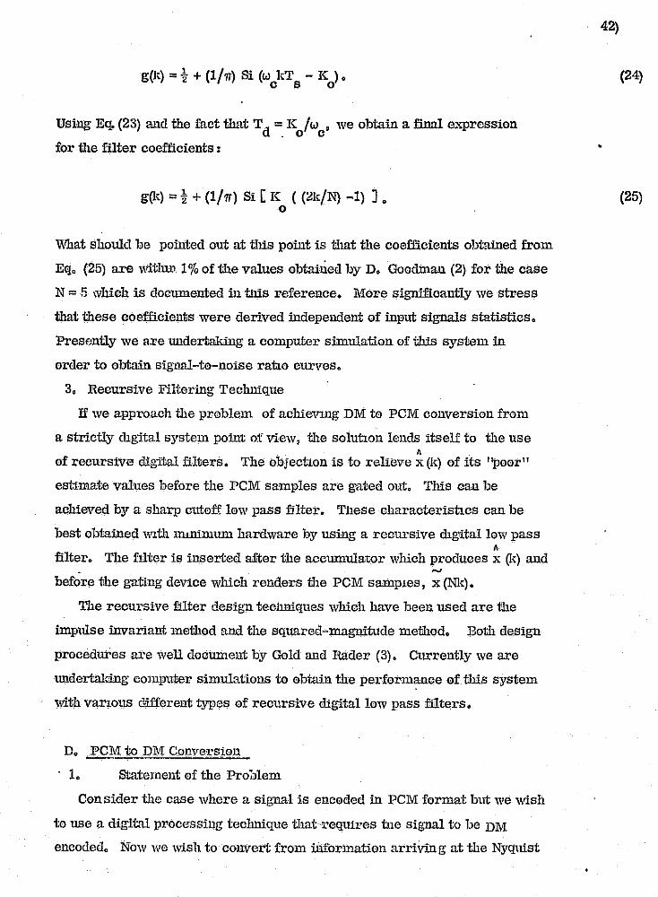
g(J-) = t + (1/ 7T) Si (w kT - K ). c s 0
Using Eq. (23) and the fact that Td = K /w • we obtain a final expression . 0 c
for the filter coefficients:
g(J-) = t + (1/7T) 8i [K «2k/N) -1) J. o
What should be pointed out at tlns point is tllat the coefficients obtained from
Eq. (25) are with11'. 1 % of the values obtaiued by D. Goodman (2) for the case
N =5 which is documented in tllis reference. More significantly we stress
that these coefficients were derived independent of input signals statistics.
Presf;ntly we are \Uldertaldng a computer simulation of this system in
order to obtain signal-to-noise rauo curves.
3. Recursive Filtering Technique
If we approach the problem of achievlllg DM to PCM conversion from
a strictly chgital system point of view, tlle soluuon lends itself to the use , of recursive digital filters. The Objection is to relieve x (k) of its ''poor''
estimate values before the PCM samples are gated out. This can be
achieved by a sharp cutoff low pass filter. These characterishcs can be
best obtained WIth lIUllilllum hardware by using a recursive chgitallow pass , filter. The filter is inserted after the accumulator which produces x (k) and
. ~
before the gating deVice which renders the PCM sampLes, x (NI.).
The recursive filter desig'n techniques which have been used are the
impruse invariant method and the squared~magnitude method. Both deSign
procedures are well document by Gold and Rader (3). Currently we are
lUldertaking computer simulations to obtain the performance of this system
with vanous c1dfferent types of recursive digital low pass filters.
D. .R9lI~ to .DM Cpnvet'sio.l1
1. Statement of the Pro ;Jlem
Consider the case where a sigTh'l1 is encoded in PCM format but we wish
to use a digital processing technique that-requires tue signal to be DM
encoded. Now we wish to convert from information arriving at the Nyquist
•
•
(24)
(25)
1;1
·.··1·.·.··
..
-·r .... ~ ..... .. Jc.

o
o o il
I , I
[I :/
iJ t]
o [J
:] il , , !
, i : I
II , I I I
" _" "" - ,,, .. ,,,,-;-: __ ,,~,~,~r,""'-,,",,,,:,,",p"",~:"f""'1"'~""""""""-·',.~"<""f·'~-'''' .... :.~~~ :_,,,,,,,,,,,,,,:,,~~''''~:~~_ew~,''''.*'''=' -, .,...,i .. ..,.,..".,., ... _" ,k ..... ~~'""."'"_ I¥'!"""j"""'''''''''''''' .. '---~------.. - "-~--~, !':,
43)
rate, 2fm
• to a DM form which has a frequency !>f occurence which is N
times faster. That is, the DM operating frequency IS fs = 2Nfm• In
addition, we would like to confine our conversion technique to all digital
hardware.
It is evident that this problem is much more complicated than the
DlIII: to PCM conversion problem considered in the previo\lS seCtion. In
PCM to DM conVerSlOn we do not have informat'1on about the signal
excursion between PCM samples and a DM estimate can follow several
paths and still pass thru the given PCM samples. Thus we mllSt address
ourseh'es to a method which first obtains additional sample values between
the PCM samples and then uses these to choose the correct DM estimate
path. Since the DM estimate is directly related to its output bit stream for
a prespecified digital adaptive DM' we will have them achieved the desired
, conversion.
2. Submultiple Sampling Technique
Altho ugh there are many approaches to this problem, the solutim,
presented here is consistent with preViously developed conversion methods
in that it appeals to a basic theoretical principle and results lU a system
which is easily phYSically realizable with the current state of the art digital
hardware. We normally expect that the best way to demodulate the PCM
Signal would be to pass it thru an analog 10 w pass filter. By doing tbis, we
extiact all the information TJetween PCM samples. However, we seek only
a finite number of additional sample values between the PCM points. In
order to achieve this, we use a low pass.filter which is not only digital but
which 'operates in a submultiple sampling mode (4).
When a digital system operates in the submultiple sampling mode it
means that the system produces outputs at a frequency which is an integer
multipl.3 of the input frequency. This is exactly the circumstances that exist
when we derive additional sample values from the PCM samples. To facilitate
the entire PCMto DM conversion process, we cheese te operate the submultiple
digit[rllow pass filter at the deSired DM frequency, f = 2Nf • Then we can s m
use these values as the input to the digital adaptive DM that we are employing
and therefore automatically generate the necessary DM bits, e (k). '1'he enly x
'oj
~ :~ ,
•

~':'. f.
I"
l
o u u u u
u u
! I u
! I : ! Li
U U
[]
0
'n .' ••••.••• v"' .• ,,-· ... ·'''""'· •• ··~,,·''·,··,:· ~"'.·,~,.,._ ... _"'.7 .. ~7m • .,.,-~".,~' .. *' .. ~,.,...~ ... ~.\.f"'T'"".~., .... -~.---~ .. ---.. ,~.-., --_ .. -----,.- .. _--- - .... '" ,.-----, .. -.--~ - . ~ .. "'. ',~
restriction 10 this technique is iliat ilie DM must operate at a high enough
frequency so thm there is negligible error between the output of ilie filter
and the resulting DM estimate. The general block dingram of the PCM to
DM converter is given in Fig. 7.
In order to thoroughly describe the submultiple sampling technique iliat
we are inveatigrrting, it becomes necessary te dichotomi ze this technique
into two types. The first type uses ilie PCM samples as inputs to tile digital
low pass filter for enly T = l/f seconds. In the time between PCM samples, s s (N-l) T seconds, we insert zeros or no ihput; This is analygous to tile s situation where the filter input is a series of impulses. The second type
employs the PCM samples as filter inputs for NTs seconds. This is similar
to the PCM samples being held for the Nyquist period.
1. PCM Samples wi111 Zeros IuserlJed
We shall describe 111e 111eory for bo111 cases in a general fashien omitting
the particular characteristics of ilie lew pass filter. Furthermore let us
start wi111 the ordinary Z ... u'ausform of a digital low pass filter represented
by G(z) and ilie input and eutput of this filter specified by X(z) and Y(z) res
pectively. Then as we normally eJ • .'pect,
Y(z) = G(z) X(z}.
In aildition, we require that ilie input occurs once every Nyquist sampling
period, TN = 1/2fm•
It we want 111e output to occur n times in 111e Nyquist sampling peried and
111e input, which are PCM samples of. X(z), to have zeros between 111ese PCM
samples, then 111e el.ltput is e..'\.-pressedas
Y(z) = G(z) X(z) , n n
where
., ;:~
44}
•
. (26)
(27)
L.D;". -----

r'· 'i - --
! ' . ,
r ..
r '--,
,{.
t : , ,. f r [
r I r L t C
[.
0 0 0 0 D
0 0 o o n '-'
n j i ... ,U
a u [J
[J
~.. []
, rl ,-,
-, -"; .. tV" _".Y"."" " __ "~'"""_.':;:"":-_~'~'::~~:!'-::'~-::''''''C'7':",-.. ~~.~~:'~''''''7~.:o:·> t __ ,_.' ~.:,~}I' F·;',-IIf!'l\I'''~~·I~~ -, - "'~-'!!
G(Z)u = [ G(z)· J z=zl/n
TN=TN/U
•
G(Z)n is referred to as the submultiple sampling z-transform of the digital
low pass filter and is realized exa,~tly the same as the ordinary digital
filter except delay elements are reduced by a factor U and scalars with
the constant TN included are attenuated by a factor n. This implies that
the digital filtei· operates at a frequency 2nf and for only one out of every m
n cycles is there an input which is a PCM sample and not an inserted zero.
The filter operates on these inputs to produce estimates of the signal between
PCM samples.
2. PCl\![ Samples Held .
In order to obtain n outputs per Nyquist sampling period for the case
when the input PCl\![ sample is maintained as the filter input of all n cycles
of the Nyquist period, it is necessary to employ a digital hold Circuit, H(z) ,
!liter X(z). A digital circuit to hold ane value as its aut put for J periods
when the held val.~le is the input during the first period and there is zero
input for the second thruthe }h periads has the transfer function:
R(z) = B(z) A(z)
J-l =L;
i=O
-1 z . •
A block diagram of this J period digital hold circuit is given in Fig. 8.
If we incovporate the hald circuit into our digital low pass filter aperating
in the submultiple sampling ,made then we :must hold the PCM sample for n
filter cycles. The desired PCM-held output is given by
where
, 45)
(27a)
•
~,;
(28)
]
1 "
.~ .•. i ;,1
:~

;.;
u u II [J
u o [J
[]
II II ..
: i i~ !
. ,
LJ
:1
n-l
H(z) =2.: z -i/n n i=O •
This completes the general theory for l)oth types of the submultiple sampling
PCM to DM conversion techuique leaving the option to choose whatever digital
low pass filter characteristics that may be desired and to set the number of
filter cycles per Nyquist period, n, to be a specific number, N, which is
large enough so that there is negligible error between the output of the filter
and the resulting DM estimate.
3. Normalization
46)
Because the DM can suffer from both slope overload noise and granular
noise due to llil input which is too large or too small, respectively, we should
ta}m the precaution to insure that our digital low pass filter does not contribute
to either of these degradations by amplifying or attenuating the input signal.
This can be accomplished if we normalize the filter transfer function in the
frequency domltin. Since z = exp (jwTN
), we normalize G(z) so that at
UFO it will be unity. This normalization applies to the first type considered
were zeros are inserted between PCM samples. If we call the normalize'"
low pass filter transfer function, Gt (z), then
Gt (z) = G(z)/G(w = 0)
and
Using the normalized transfer function, the t1.'t1e filter output is .
Y' (z) = Gt (z) X(z). n n
r-.. ..--.---~.-----
(30)
(30a)
(31)
I
I I
. , ,
,-]

o D
o o
il ,-
o lJ
'1 I
,I
, !
'I
I' II ~
I ~,- ,-
4,$ i ' »a;;a ;; »iM' 4 ;
For the we of converter when the PCM samples are held we seek to
normalize G (z)n so that at w;: 0 this will be unity. Let us denote the normal
ized held transfer function as Gil (z) which is then given by ,n
Gil (z) ;: G (z) / G (w = 0) • n n n
Now the true output bacomes the expression
y II (z) ;: Gil (z) H(z) X(z)" H n n n
4. System Evaluation
47)
In order to determine the performance of both types of PCM to DM converter
we are under".aldng two different approaches. One will be purely analytical in
which we letx(z) equal the Z-transform of a sinnsoid of freql!ency fm which is
sampled at the Nyquist rate. After G(z) and n are chosen, we can find the ztransform of the filter output; tltke the inverse Z-transform; and then evaluate
the mean square error.
An alternate approach will be to completely simulate each type of converter
and the desired sinnsoidal input on a digital computer. We can use the Fourier
analysis technique described earlier to determine the signal-to-noise ratio of
the DM estimate. This will give us an even more accurate measure of the
quality of the conversion system. In both approaches we can vary the filter
characteristics and observe the effect of filter hardware complexity upon
performance. The latter approach also allows us to vary n and observe the
different system performance in terms of a change in DM estimate signal-to
noise ratio.
". ',---"---j
(32)
(33)

r , ;
r I t
r ,\
f' I,
[
f. ~,', , , .. ~ ! ~'. ! ! ~.
~ ,. ~. :':: ~.
'. " . ;
~ , , L'
lit :,<: k'.
l ~,' 1,.-',""
F~'
t~
:
l !
0 0 0 0 0 0 !l [J
!J
0 U
[1 !1 LJ
i ! \_1
i ,
U
References
(1) CD L. Song, JD Garodnick and D. L. Schill111g, ''A Variable step Size
Robust Delta Modulator", IEEE Trans. Commun. Tech., vol. COM-19,
pp. 1033-1044, Dec. 1971.
(2) D. J. Goodman, "The Application of Delta Modulation to Analog-to-PCM
Encoding", Bell Syso Tech. J., vol. 48, pp. 321-343, Feb. 1969.
(3) B. Gold and C. M.Rader, "Digital P:rocasS'illg of Signals", N. Y.:
McGraw Hill, 1959, pp. 51-70
(4) B. C, Kuo t "Analysis and Synthesis of Sampled-Data Control Systems",
Englewood Cliffs, N. J.: Prentice Hall, 1963, pp. 82-86.
("" I~
~ •• ;,., :,' ,,'7.-~--.,. ~----= .,' , --------------~
48)
•
'r-, '
, , -,
iJ .~
.~. .. . ' .~
j i j ...•. J
1 ·1 I .~

~-
u
[J
o
u u -':'1
I ! lJ
n L!
APPEl\'DIX
Dlrcct Arithmetic Processing Of Delta
Modulation Encoding Signals
J. L. LO CICERO, D. L. SCIJIL1,ING and
Dept. of Electrical Engineering
J. Gl\nODNICK
GOldrnark Communications Corp. Stamford, Connecticut
Abstract
The cl:ty College of the City University of New York '
In this paper \,,0 shO\-/ that t\10 or more Del ta Bodul" tion' (or-I) encoded signals can be added or multiplied without first converting them to a Pulse Code Modula.tion (PCM) format. These results are obtainea for a large class of all digital adaptive DMs as well as for the basic all"digital linear DH. The addition and multiplication is performed by oper,a ting directly on the Dt-1 hi t s,tream and the sum or PlfOduct signal is presented as cit,her a OM bit stream or ~n a PCt-1 format.
Bounds are given on the Signal-to-Quantization Noise Ratio (SNR) for these DM arithmetic op8rations and compared with the results obtained in PCf.l. Experimental results are presented \-lhieh verifrr the theory that has been developed.
Introduction
The conventional approach to arithmetic signal processing is to first encode the signal in Pulse Code J.lodulation (PCB) format and then digitally process the PCM signal via standard pa.ralleL processing techniques. it is becoming increasingly popular to encode signals in Delta Modulation (DM) format, whe'J:~ niqital data is presen,ted in a serial rather than a pa'rellcl fashion. If we \",ish to ari1.:hmetically process 0M encoded signals, it becomes necessary to perform the addition'al opera ticn of conversion from DM to PCM before processing is initiated. It is, however, li'JOssible to avoid this additional operation of conver-sion and to produco the sum, difference and even the product oI DM encoded uignals by direct arithmetic processing tlf the .serial data.
In Fig. 1, we show the basic form of a digital DB. Here \<e have assumed that the input signal., ,,(t), is bandlimited to fffi' and is sampled .. ell above the Nyguist rate, 1 .. e., £$» 2fm_ The most general mathematical description of a digital DI1 is given by the following set of equations:
e,,(k) = 5gn[ ~x(k) J, (Ia)
A
; (k) = ",(k) - x(I<) (Ib) ,"
and A A (lc) x(k) = x(k-I) + S (k). x
where Sx(k) = step size at the kth Interval.
The particular type of DB is specified by the step size algorithm used. to formulate S" (k). For the linear DH,
·S (k) = Se (k-I). x ){
(2)
where S '" magnitude of the minimum step size.
. Although there are many step size algorithms "for adaptive Dl-1s, whe.re the step size adapts to the input signal power, we shall be concerned with the cla.,5s of Dl-1s derived by minimizing a m'ean square cost function, i.e. I those described by the Song Algorithm [11. For the case of the Song audio mode OM, where the step size increases linearly,
S,,(k) = !Sx(k-I)\e,,(k-I) + Se,,(k-2), (3)
and for the Song video mode DM, where the step s~ze increases exponenti~11y,
S (k)=!S (k-I)
I ; 1 :!J I IU
u u
i I J
I , J
u
, i
I ' . I
IIddition/Subtraction of ON Encoded sianals
Cf,'lH,.'.tC'\t' L\\'" r_~'q" .. '111. n,(t:) .",,1 V(t) I 1101:h Il'I".11tlldtr1d ,,, 1'11\ (wd l'l1th Pt·, t""'lIlt"11 tin ,,,.tI \ ... " tlHI\' h'\\'I' Illfl 'Itlqlll1l1"~It1fn'I{I~) 1 'ttnlt lOy (ld I Itvlll IlilitH. 'I'hlln fHIllId, III' till' prohllllll or: ohllltnl.nq tho I1UI1I or lhono two 01'1n:\ln. Wr~ en" pp.J&form llr\,LhmolLc pro-em,"Jnq on {ox (It») "lId (Oy (k») "lid form tho d Ixcc~t: UUIll, ill) (It), on t:ho own of tho i11lHvldual. n1.qnnl unt..il1lnt:on, i.a.,
Using tho DM expression for the estimate of x(t) and y (t), Eq. (lc), we can form a recursive relationship for the direct sum,
aD(k) ; aD(k-l) + S,,(k) + Sy(k). (6)
where Sx(kl and Sy(k) are formed directly from (ex (k») and (ey (k)).
The direct sum, an (k), is available in PCH format, because of the recursive relationship by ""hieh it '.'laS formulated, Le., Eq. (6). To obtain the ON bit stream of the sum, (e (k)), we merely pass aD (k) through a aigital OH. II block diagram shmoJ'ing the structure used to obtain the sum of the DM encoded signals is presented in Fig. 2. The m·l digital feedback circuit shown in this figure is, in general, constructed with the appropriate step size neb-Iork followed by ija accumulator. Nith this in mind, we notice that in 0raer to physically realize the entire OH direct sum system, it requires only a full addel:", an accumulator and the necessary step size netwo,rk r all time shared.
To subtract DH encoded s"ignals, we just add the nega tive of the suhtrahend signal. l.f we ,.,ishec1 to form x(t) -y (t), all ",e need do is change +Sy (k) to -Sy (Ic) in Eg. l6) and the re.sul t ,·muld be the direct difference.. Thus, subtraction takes the same s,t·ructur'e as the addition sho\'1n in Fig. 2.
It is to be noted that the structure derived is completely independent of the type of DH and is therefore universal for any dig'ital OM. In order to realize the direct sum of signals encoded by"a particular type of Dr-t, we must construct the circuitry used to formulate t'he step size algorithm employed in the original DM encoder. For. the modes cited above, the step size circuitry can be constructed using the standard digital hard\·,are i.e., full ad6.ct:s, dela~ls, scalers and Exclusive - 0R gates. The DM adde-r for the linear mode and the Song audio mode is shown in Figs. 3 and 4, respectively ..
50)
Avcro~lng Filter
'.llhl'l rllr,.1t1V tlll'1I" 1·"11I'OIIfH1 ut nll tY(JHIJ (lr 111,,11111 IIHII If I II l'fI'Hstl111l. 1111"11. Itt 1111 1111 LI III/I I It II Iqllll I \llldt'lI l1)ddl.!l" 11 '1,,,I,,,llf1 Jtltl.l.f!nl. I"or /I 1III'1IIr llt1 1.110 ttlfttrnflt.tl 1.1.1 n nllllp10 flflll/H·n wnvo with n !lor.iod or t:\t1O nillnplJnrl j nLcrvn] II. For llny !;on~l mc.Jclo DM the pel;:i.cul .1 n f.our. [Jnmplln~1 intcrvnI-,n. In FJ.q. 5 we uhow fl typical Dtcncly ntato ont:.tm:tb(~ nl."nl11 (or thr~ Honq l.luc11o mou~. 1.n th.l.l1 f:lqul:e, tho conutant input,. x, han b~t:!n qUilntizcu to Xq and m ia a non-negative integer.
since the direct sum, aoCk), produced by a Ln-t adder wus formulated as the sum of the individual signal estimates, \-;;q. (5), we naturally expect the direct sum to also exhibit a periodic pattern when ;rsspunding to constant inputs. For the Song audio mode, the::-e are four possible steady state direct su~ waveforms; one of which is given in Fig. 6. In this figure, nand r are both non-negative integers. The important property of the fc.ur"rx>ssible steady s ... ate direct sum patterns is that ·the arithmetic average of Rny four consscutive values of a-o(k) is always equal to ~ + Y, _ This fact inspired the use of a four ~erm non-recursive filter a!t.~r aD (k),
The four term averaging filter employed is described by the £ol1o;/ing equation:
A(k)=Ha (k)+a (k-l)+a (k-2)+aD
(k-3)]. (7a) ,D D D
If we apply Eq. (7a) to the waveform given in Fig_ 6, the result is
A(k) ~ Xq + Y q (7b)
for all k, as long as aD(k) has reached the steady s'tate. Thus it is seen tha,t after a four term av.eraging filter, the DM SUIT! produce!: the same result obtainable by PCM addition.
In order to illustrate the function of the four term averaging filter, we form the digital transfer function, H (-z) • Assuming zero initial conditions and taking the Z-transforrn of Eq. (7a), we obtain
A(zL -1 -2 -3 H(z);· ;i(l+Z +z +z ).
aD(z) (8)
To display the frequency characteristics of this filter I ''Ie let z = exp(jwT) and form . .
H(w) ; e"p(-j3wT 12) cos(wT/2) cos(wT). (9) where
T; Ilf . In ~·ig. 7 ~e plot IH(w)l; Icos(wT/2)cos(wT)I -on an abscissa norm ali zed to fa.
From Flg. 7 t we observe that H(w) has a zero at 1/4 fo' 1/2 fs and 3/4 [s' It is
NTC 74-393

1"".' ~ ~:-, ~.
~.
r ~ t t:
[.
f t ! ~ ~ ,. i f' i k
1
, , & --:,:-~, , ~--.
r
~>
v
~"
c R I' , . :1::'
if It· O' :~, , r ~-
~.
'--I
:J I u J i J
J ,
:J , 1
:1 ]
I
" , . : I :_ J
I 1 f
.J
I
precisely the zero at 1/4 fs that elimJ.n· atcs th-a (our sampling interval periodic componcnt produced by the Song mode DH. \~c nlno note thnt the foul" term nvcrnging filter cxhibit:s lo\~ pnnn (ilter ch<l.t:'.1ct:criflticn nince it ~l1itJhtly ':tttcnUut:cs even baseband froquencies. ThuR care must be. taken in utilizing this filter, because it can introduce some distortion to baseband signals.
HuitiplicLltion of Dl>"Encodcd Signals
If \Oe "ioh to multiply x(t' and yet) and if \Oe only have the sequ(mces en (k) ) and
Jey(k») avuilable, then w" can f~rm the irect product:, p (k), by using the pro·
duct of the inc1iv2dual signal estimates, i.e., /I"
PD(k) = x(k) y(k). (10) As is the case of the direct ::mm, we can develop a recursive relationship fer.the direct pronuct,
PD(k)=PD(k-l)+S (k)J\(k-l) +S,,(k)~(k-r)+ S,,(k) Sv(k). (II)
The basic block diagram snowing the direct product, both in PO! format [pO(k)} and in DM format [ep(k)}, is given in Fig. 8.
Since the direct product, Po (k), is formulated as the product of the lndiv-idual signal estimates, as in the case of the direct SlIlIl, \<le expect the direct product to exhibit a periodic pattern \-.,.hen responding to constant inputs. Similar to the direct sum, the Song .:ludio mode exhibits four possible steady state waveforms for the direct product. In Fig. 9 we show a typical steady state waveform-. The cons ta n ts C'l and c 2 depend upon x q and Yq and the ampli tude of the s·teady
~ ~) state error pattern (X-Xq and Y-Yq, ·while d1 and d 2 depend only on the latter of these two. Notice that the arithmetic average of any fou·r consecutive values of Po (k) is always equal to Y.CJYq plus a second order term depending on 52. This warrants the use of the foll0\"ing four term non-recursive filter after PD(k):
P(k) = HpD(k) + PD(k-1 j + PD(k-2) + PD(k-3)J. (12a)
Jlpp1ying Eq. (12a) to the waveform shown in Fig. 9, we see that
P(k) = x \. + -~(dl+d,)S' (12b) q q -
for all k, as long as Pn(k) has reached t'he steady state. For any reasonably small value of step size, the term 1/2 (dJ. +d2) 5 2 is negligible and thus, after the four term averaging filter, the DH produc·t yields a result. almost identical to the PCH product.
Returning to Fig. 8, we observe that although the structure derived for the di~eet product is again seen to be universal.for nny digital DH, it will only be useful if the step oize algorithm
394-NTC 74 f •
ia ~Ilch thilt we can recllrsively ·reali?e the partinl products, that in, the last three term" in 1':'1. (11). For the linear modo thiu is n<>t clHficult, and tho diroct produc t io j!Jccn to bo
PD(k)=PD(k-I)+SCy(k-I)~!k-l) (13) +scx(k-l)y(k-I)+S cx(k-I)ey(k-l).
51)
In Fig. 10 we show the black diagram for the DM multiplier for the linear mode. It is lmport.:lnt tc: ~>~int out that the ease in. realizati.on of the direct product for this mode stems from the fact that there are JD non-linear ope-rations involved, only simple scaling and multiplication by +1 or -I.
In order to recursively realize all three partj,al products for the Song audio mode, we must use the £0J.10\·.'in9 step size re- ! l:ationship which is a property of all types of DMs:
Sx(k) = ISx(k)jex(k-I). (14)
From Eq. (3), '·le see that this property is applicable: f0r the song audio mode as Ion; as Is (k-I)I"S. Employing the step size relati~nship, ~hc partial products for the Song audio mode can be expressed as: Sy(k)J\(k-l) = By(k -I )~(k- 2)c~ (k-I )ey (k-2) (15) , + Sx(k-I)Sy(k-1 jCy(k-l)eylK-2) + ii(k-I )Sey(k-2),
Sx(k)~(k-I) = S" (k-I )~(k- 2)"" (1;-1 )e,,(k- 2) (16) + Sy(k-I )S,,(I;-I )cx(k-I )cx (k-2) + y(k-l )Sex(k-2).
Sx(k)Sy(k) = ISx(k-1 )Sy(k-I )Icx(k-I )ey(k-I) + SISx(k-1 )Jcx(k-I )ey'(k-'2) + SISy(k-l)Jcy(k-1 )ex(k-Z)
+S'ex(k-21e\.(k-2), (17) It is easy to see that Eqs. (15), (16) an.d (17) can be constructed using adders, delays, scalers and Exclusive-OR gates. In Figs. II, ]2 and 13 \'Ie show the block diagrams of the partial products for the Song audio mode as specified in Egs. (IS), (16) and (17) respectively.
We can also construct a DM adder and multiplier for the song video mode, as defined by Eg. (4). They are similar to t'he Song audio mode uf:.wices, since the step size algori tlur. takes on a comparable structure. Likewise, the Gtep size relationship given by Eq. (14) is also applicable as can readily be seen from Eg. (4).
.It is important ' ... 0 realize that all of the systems previously mentioned are accumulator or positive feedbaek type. For both the adder and the multiplier, f.or all OM modes, the present outpu.t is egual to the past ontput plus additional terms. 'rhus it is significant to begin with the correct i&lit:i.al cendition for the past output, or else suffer a constant offset error. It is convenient te start \ofith both signals, X (t) and y(t), at zero so tha t '-Ie can employ a zero in1 tial cond!tion for the post output.
. .. "

: I J
i I .-D
r ·U
~, .. ~- . 1J
I
f'-
i]
I
I:.
'-'--'~.:~'.', .~, < .-,-.".~,.--,.. -"'~_:-':-r:,-,\~,~-"",r'·.~":,"""~""""'~':"'-~:,,,,":,,,,",,~",~ .. =>~.3~-:=~;;:"""-""''''''.<>.>~' .",~.",> ~-. ",,,. ~n~> ~",-... ",_ t.~>,,"1~'"1f~''"''> W .... ,~''''. "'''$i~.",.~_i,~'",,",'''''''(\1 - 1""' .. .., .. "''''''~ ...... 1':''!!II . _________ ._____ _ .-------------~-- -',' - ',-, ,'-- ~. ,-~:.~ "f-~'~~--;1---·'--,-,
Signa1-'ro-Noise Ratio
The signnl-to-noise ratio for the sum of t\'o PCH encoded signals is "ell-known (2), nnd is given by
SNR (rCM) ~ 6(0' '+0' 'lis'. (18) a x y After nonrecursivc averaging, the error in a on enGodecl signal can be shown to be p-qual to tha t of PCl-1, and hence fur a constant input,
SNRa (DM) ~ SNR. (PCM). (19)
The signal-to-noise ra·tio of the product gf tV10 PCI·! si<Jnnl~ is nl~q ~,ell-l;n6W!l ,111<1 is giVCl1 by 14411 tt
SNR (PCM)~ 12(0' 2+O'X2)~2 + S4 (20a) p " 'l If the bm signals have equal pot'ler and
the step size Is small (17 '=0' '=(7'»S'), the SNR becomes x Y )
SNR (PCM) ,. 6 <1' /S' . ' (20b) p
For the direct product of lJM encoded signals we can develop an exp:ression for the sign'al-to-noise ratio. Again, we include the averaging filter intl·oduced in Eq. (12a) and the DM error is formulated a9
~r=P-P' (2Ia) where
P = P(k) = "qYq + OS'. (21b)
Let us now define the product noise ratio for DH signals to
SNRp(DM) " ?/var(~p). Slnce 7 = ux
2 u; • we evalunte
1; = os', 72" =? + o's. 'P p ,
and
But this means thut Var(~p.) ~ Var(£ ), , p
and 1440' 2 a ·2
signal-tobe
(22)
(23a)
(23b)
(230)
(23d)
SNRp(DM) ~ 12(<1'+17 ''')i+ S. (24a) x Y
Again ta'king' a} = a/ = f12 and a 2» S2 , this result becomes
SNR (DM) '" 6 0'2 /S'. (24li) p
As in the case of addition, the oorelusion is that the performanee ef the dil;:eet 'PCM multiplier followed by the averaging filter is identical t9 the PCM rnultip+~er
. performance for constant inpu,t signals.
Sirnula tiD_n Resul ts
A computer simu1.ati0n ha-s been completed for the direct an-ithmetic processing of DM encbd~d signals, and results have been obtained for both the direct sum and the direct product employing the Song audio
ORIGINAL PAGE IS OF POOR QUALITY
52)
modn PM. Both the direct Bum and the dir-(>~:t prodttct were pansed t.hrough the nonrccu.c~;ivc four term averaging filter mentioned previously. 'l'he sum results are shown in rig!;.d4 lhru 10 und the product results are shown in Figs. 17 thru 19. In a11. simulation results both the step size and the sampling period have been normalized to unity.
Fig. 1.4 shows the sum of a step functi~n and a pulse; Fig. 15 display-s the r.esult cf adding a Gt~p function and a sinusoid; and Fig. 16 gives the addition of two si~ids with the same amplitudes and -Crequencies tl111t ilrQ In Ilhilti" , In l'igB, 17 I 10 amI 19 we Sh"'\1 the proiluct o£ the signals thai: were added in Figs. 14, 15 and 16 respectively. These simulation results verify. the theor~{ developed for bo,th the DM. i Direct sum and the D1>1 direct product. ~le mus'c particula·rly emphasize the role played by the f0ur term averaging filter to achieve both sum and product results tha t ar.e so accu-ra te. To fully apprecia te the e,ffect of this four term averaging, we show in Fig. 20 the direct produet.of a step and a rulse without the four-term averaging. Comparing this \"ith Fig. 17, which is the result after four term averaging, clear demonstrates the importa:nt role played by this fi;tter.
As a concluding remark, \'le observe an interesting. by-product of the Dt·1 rnul-tiplier. In Fig. 21 we show the response of a Song aUdio mode Or.1 to a step of amplitude. 150. The response time, needed to reach at least 150, is seen to be 17 sampling periods. Notice, frOID Fig. 18, that for
,the multiplier to reacb an amplitude of 150 it takes only B sampling peri0ds. Thus we nave expanded the band\~Tidth by a factor of two, cczmsistent \'Iith the previous assumption of the multiplication process. This type of system may be useful when processing video signals that are charac-terized by abrupt, step-like amplitude va·riations.
Ref.erences
(lJ c. L. Song, J. Garodniok.and D. L. Schilling, itA Variable Step Size Robust Delta ~10d.ulator," IEEE Tra,ns • Commun. '.rech_., Vol. Com.-J:9, pp. 1033-1044, Dec. 1971.
(2J J.M. Wozencraft and I. M. Jacobs, Prirciples o-f .communication, Eno:ineering, N. Y.: John \Yiley· &- Sons, Inc., 1967, pp. 674.,.676.
NTC 74-395
-,J
', ..

~:,
r- o [1
~.'.' ..•. ' t ~,' • t' o
! I
~ . 1
~-: :,',.
u u []
Ll 1
.J
'~.-
,"' ro. I"
~ ;)"-t:- lJ ~,.';
, u , " ~"
, k.--';/ '
--.....:--'--- .. ~,:"~" - '~~':~·":'-:"'"'T,O:'::"-.,~."""",i"~-'_ .. _, _, ."""; .. '":..~""f."'."'{....---~::-"
'" I B .... , .... ". e-, ... l*I
'q' [U .. ~"',, l •••• ' u".
'Q""'H , 0 ..... !tJ '- D ~~'I "."
3BO-NTC 74
. , o '. !.,tU 4'
t,!>-l'1
'.
1 ." II~ I! ... (0'_ t_,lf:Il ... l.,q a_ u .. PQ;I _
r ... c_ ... t_ 1.1
','r,
'lft , • .., ..... eo ... ;..., .. , ...... .., .. _, ..,c_ ... ,_
ORIGINAL PA,GE IS OF POOR QUALITY
53)
'11:1 Y. "..,...,..,,,._, r ..... ' ....... of ... ,..., , .....
II .. ' .. ' ..... ~""I"'O , .. ..
•
I
'IfO Itt""SI ... OO"l" ..... " .. .,. ..... _U.,. .1110 C ......... ,.,.....
tt~1
I SJkl SJkll-8\ " -.~-;(!;o---r-- ',hlln-n
1I,I1-ll~.I\·U
1---(.:)-,1
_.nl ttll
G;ISJkll-0.,.(~+-~.).· ----,- _,I',{;"n
" ",HI_,ll.\!
, .
---____ ...c:.:::=================:=' .... -----.... ==~-=:"~.=:""'~-~.~~~J'. .. '~
I~ i I ,
, I i ! ',', I I,
::-.

r-' I , U ~.
~- . :'-
t 'f
L 0 t , ,
0 ' . ['-
t u v [ , . J . ' t ,
! ! I , I '.:' k \. ,
k U r-
o~ .. 'j I • u·."lI
" " " ~; • ;,:_.- U >:+--i,',·
• , .. " " n ,.,,. COol_of!>" .......
~~.
II ~.
;.
~ .. 0
(- ,,-)-p ," .. ~/c 'IJ ;'?-,.d'
" " •
f: LJ ~.
~~. '.
0
" 0l0I_.1,,,,,,,,,"011_
f~
[l ~
t!118,,, .~
'!>It . , M , "
1 • • " •• .,
" " " .. " • 'ot .t f* ••• ot , .. \1_., .
;;' i ,
! I , ! I
.,~J .. "i L 0 ,., '"
;~
I ". , ~
'" "
0 ." , " • " .. .. " =~ot.""'''''_
rJ
n
»~l
.. " ~ ..
" .. IO' U
,
"
" ..
" ~ " ,,, .1--_-" ... . ., ...
fll It ~ ,,,, .. , II. 10. "'.,1_
"
54)
•
/
11 'OlSro1S10U~OOOOM ' ... I)lol ,...., ,I Tn '-"t
.:J All)
140 • .. = o .. .. .. • o , 10 ., '0 ·H J.D U ~O'
tllftl. r.q ...... ~0IJ" .. _11J.1'.
,~ n 'I~_ ... D 'JU
"' U,
'" .., ,,, .. " " ." ~
•
'1 t!.-
.~
10 " '" ,. In--,-,---''III tt.ori 1'lI ........ ,~. _ .... of ._._ ,_t ...... ~n...
'.
". "
.'
NTC74-391 . ,
f ,
'!
i ,
I I 1 l 1 I , , I I l ~ ~

~,
iJ
U [J
I]
Ij , I I
- I
,I
U
0 0 IJ
[1
I]
I] '-I
il 1-1 - ,
I i I i [1
~I
.... '"
,.... .:r:. .....
'" Q)
, .. .-t
;i . 1
I
,.... .:r:. ......
>C '-AJ1
+ j + ,....
..!or! ...... ><
0 "-<:[
:: I C/)
...l ~ ~ I- u
• .:t <!) OJ -0 0
W :2 w Cl IJ..
-.:.<: ...... (><
~ 0
C 0+-
'0. 0
I
« j:: c .... 0
E ... 0
IJ..
1.:1 ... Q) G: Q)
(!)
. .-f
0'1
IJ..
I I I j -,
~
"
"
2"
\,
,I .~
'1 J -,
Of'

r1 J
k t !
f: 0 t , I
~- u J, ] , r f' [. t r ~"-- I , I L I t·-,. ~.
t~·
j , " ~' ," r 1 ~. ;."
t [i i"e -
" ~-, r 0 Ie: :'; >:;",
~-::. 0 f':,
~' ' ~j,-0 /,.
r;>.'.
.... ....
I~'_:·' ,.
i: I
rl
!]
i
l
....
....
I I~ .. ---- ~ ----.,.,-1
.... ..... .... ..... 1
..... .... .....
I-"' o;t
------- --.--~-.-
1:: c ....,., Ul c: o (j
<t o I-
Q) Ul
"" o 0. iJI Q)
0:::
:2 Q
•
. .
1 j
·1 1
1 ,1
1
,~,j I ;;;
!'"j' ...•....•... : ...•.
J
:.'
j d , l:---

u [l
o o o lJ
J iJ
'1 ! i i J
!\
• I . I
.'
,
1
....... .:.:: ~ (f)
w N -(f) I
0.. W r-(f)
,.... ~ z .......
(><
I
:a: :c r--gs (!) ....J <!
I
z -
ORIGINAL PAGE IS OF POOR QlJALITY
... Q) ..... Q)
> c o
U
:2: u 0..
o r-
:2: tJ
" ·iii c an
57)
•
•.. ~
] ..•...•.. "' •..•. ~ I

~:!~:i:7~' '~-
',f-"W-j,:.-W~~:'::
-;'~-' ,,~,
"-(\
,'.
,-,;
,,,,
~,
"-'"",: '
T~':~' ~?,~~~:;~:.:nlt~? .... :·
;:" ,"':
.' -y
(~"
':T ~ •.
~'-:
'"/~
";""
~":-
:':~
:,:,
:.vr
y,,:
,,~:
: :7
';;' .. •
• .. r'·
;:;~
·,t~
f:;:
-~,:
"""'
i ':#
, ,~T
~··'
:':·
":?~
t.
:':'I'
-,':'~
:-~'-"",~,,~'"!"'J":":"
,~--
'---
-'--
2--
[ .
[ '--;
c:::
J [' ~
r-:
c.::
--.;
L
--J
c.=..
L _
_
L...
..-.1
'-
--
'-;
r N
ON
REC
UR
SIVE
D
IGIT
AL
FIL
TE
R
. ';';
, "
. .--
. .-
I I
ST
EP
-SIZ
E
Sx(
k)
I .
,"
~""!
j-,'
: "
_""':
... .£
1·~'
.:·'
.:. '.
~'1
'X{k
) I
,.
>
j o(
t}
h (t
) I
""\i
ALG
OR
ITH
M
~ I
I "
ex(k
) i
x(N
k)
Y
-y I
-----------
LOW
A
CC
UM
ULA
TO
R
PA
SS
,
FIL
TE
R
/1 ,1
>'
'
PU
LSE
fN
T
RA
IN
'1
Fig
. 4
. D
M
To
PCM
C
onve
rter
W
it!;}
Fj,l
ter
C>1
$3
•
~ J-
! j:fi*~
~:::';
::~:~i
%i' 't'&,
:Y;4q
PfM 'r
i/-it :;
;;;;
.' ,;~
",;~~:~.
<,., r-
;;::
:~~~
:;~:
~=~i
~~~,
1;;~
:~,,
~:~_
~~i~
~~~~
~);:
::i;
;":'
ii~~
':'~;"".
~~:i::~~:l-'
: "'_~,'_~(
~ ;~~, __
,'_~~:;. __ -i;
_:_'~_:.. .
~"~-'"":'
'_ --
.

.> . ,-r"" • f i "
t-.' F
L.
t ~'- :
r ~: k f ~,
~: ~:-,
f It-,-
II f' . i I-t-t~c Ii, 1:.: ,i
t ~", , .. ~~ t',' ,
"
K r f:;-i""
i( I~
:.
i,:'_
.2..:.....''-"''." I~---,-~ .. =' ~= .. :,·2:,?"-'O:;·=' "=' '''='''-''0'''''=-'''=---=-=-' , . ....., ... ___ ... '.""' .... = .... ~,......."""'. __ • .,.,.,....---,-~.....-,--~ .. ~ ... 'c .. ",'.- ': __ "',",,'<'~"""'''''"
U U 0 lJ
U
i~
!l U U n rJ
lJ !
\ i
i !
II)
~ ...I IJJ o Z
~ ~ +
2+ + I
$. ...... (x
, , w
: , , ,
0
I
I I I
~ . ,
0
..
0
I. ..... .' ., "i"' .' .....
" Z : C\l , -:::. ...... ...... ..., .. • Ol t1I Ol •
-----------_ .....
)~ . 0 ......
0>
59)
•
c .... Ol
0'
10 0>
LL
,
! ,! '1 ,
:J j
1 . <1
,j :1 j
'j lj I, \. :""··'1.'
I"
( '.'
I'j" I '
h) I'i ' .. ·,1·
j ': j ;
i ~',
I ;-1 !. 'I,' I .; i _'
IJ ! .,
I i ; /. j ." .

fl' i
~" .•. c r~ r'"
.. 1
i L
!J
u I !
to o
-------------_ ..
... (l) = .-
IJ..
11) 11)
c a..
~ o ..J
.... o (l) 11) c o c. 11) (l)
a:: c. (l) +-C/)
of-.-c ::::>
•
• -,--._-..•. . I .

~~:R;'\ ';
"V~,
,;
:.\,
:,,:
,,~~
.,
.},.
.',,
.~":
,.,-
-;-:
(,'.
-r,~
_ "'
,1_
;·"\
':';
i.
',··
?-'
," •
.--'''':}rt:>,~~~F~~'':',,:7t''f_~~,.~:7::
,-' .,-
"~,-,<
F·'}':
;i,~'·
.. :_
~:y.,-
-:, -
';T'
;-":
-F~r
:-::
~-,;
r>'"
"'.'
?:,r
""~~
;~~~
~~''
'~~~
~,?1'l~~~~~~"'--~"""":"l
----------'-----------------"----------~~--~-~
_._~ __
.J
i .,
[
""1 Ii
fs=
2Nf m
t .. .
x(N
k)
. ~
~
xf(k
)
;;F!'
DLPF
+
+
-
-1
.
, ..
::.'
,.
OM
D
IGIT
AL ~
FEED
BAC
K
Fig
. 7
. P
CM
T
o DM
CO
lilve
rte
r
r-.
[ ,
c:=
J
ex
(k)
•
r---
-'-
'-'
,. r I "
j J J j ·1 1 I , 1 ':l 'i .-i l j
· I
\ .<
i .
~ ~j"
*'_
_ ,," .. ,
ji"'"
"
•...
• .. "'
·w·,,
"""""'
"" .. ',
' *_.
..,.'"
"'"""'
.... '".
.;.;'-;;,,,~,;,L"'.'"""'''''~"''''':=''' ...
d'·
" ,
., ....
. ~,.~_~ .. "
''''''"':
,..;
.,,
.d,,
,,";
~O'~
."'.
" ....
... ~.
.. -, .

" k
~ -
r-I L
fJ
Ll
II U
D
1 I
i I !I
.~------ ~,-~-
o
C/)
f--
Z :)
>-<[ -I W
0 Cl ---t I "":I ......
o
+
+
+
+
--"''' ,. ,,- '_"~'. - 3.' __ .~,_+",""O:'~ .It,!I.9;; ."
C •. ' • " •• -. ','-'. _.n''''''~~'''''''~'''''''''''''''''''_''''_'''','_A''' ....... """"...-" •. l'!>./Q.,'
,.... N .....
I
I
I
--N ...... <[
c ..., 05> is "0 o -\: Q)
a..
62)
•
1 i

J 'd
U
LI
U
u n
;1
, I ! ,
u
, ,
63)
I. 4. A Phnse Lockcd Loop with Nonlinear Processor
A. Introduction
A general configuration for a Digital Phase Locked Loop (DPLL) is shown
in Fig. 1. The input signal, f(t), is a bandlimited (D Hz) angle modulated
waveform (i. e., FM, PM, FSK, P8K, etc.) of nominal carrier frequency
f , plus an additive noise sigual, n(t). f(leT) is the digitized version of o s f(t). where T is the sampling period, and f QcT) is the Voltage Controlled
s v s Oscillator (VCO) waveform in digital format. The Phase Detector (PD)
e:l>.-tracts the difference frequency term from thc product f(kTs)·fv(kTs)' This
signal is then hard limited, scaled, and then processed to produce the loop
outpttt Signal, yQcT ). s
Since in a Phase Locked Loop (PLL) we are interested in e:l>.-tracting the
phase of the input signal, we can consider the use of a Phase Controlled
Oscillator (PCO) as a feedback device. The frequency informaii.on would
then be the phase difference [cp QcT) - cp QcT -T ) ] / lI'.ro v s v s s Let us assume that the form of the input signal is some phase modulated
signal. The digital version of this slgnal (assuming no additive noise is
present) can be shown to be of the form
fQcT ) = -2 cos [(kIT T /2j) + cp QcT) ] ssm s
where j is an integer greater than zero and cp (kT) is the modulating m s
signal.
The VCO waveform will he of the form
f QcT) = g[ QcT Ti /2j) + cp (kT) J, v s s v s
where cp (kT ) is the estimate of cp QcT) and g(') is a function defined as v s m s follows:
(1)
(2)
l )

r' ... '1 , 1 , ..
k~
i :J ~
r ~ f IJ , I ~.
I l i ,,.
~ .. " r.
11 ! I r U , , , t-,
r' !] ~ , t • ~ ..
~ j L
!,-.,.,
r: I J
~', (,,.-, ~. (. , :-i ,,,".
~.
~ " ~
i:
f I.' ,. I
.~~..-~ __ -""""'~"'~_~iOj_.""""""'.'"')'''.'_P_foI''''' ......... ' .... u .. o.; .. , .... tlJf1 ... , ............. :"", r""' .. "' ...... ,'!'lb .. !", .. ''''.''''''''! ••. - 'i<f " -.-~,-.-.-.". -;;::;0 ~, ..,._,...n ..,.-~~ ~~ " " . ..,
--I
and
{+1
g(x) =Sq(x) = -1
g(x + 2'IT) = g(x),
Also, the VCO phase is given by
k-I IPv(kTs) = GVCO " ,t; y(il' s),
1=-00
where y(i T ) is the output of the algorithmic processor at the time instant s t = i'l' • At this point we will normalize T to unity for simplicity unless s s . otherwise noted.
B. Linem' Delta Modulator (DIll[) Type Processer
1. 8ystem Characterisiics
Consider the follOWing digital filter to be used as the algorithmic
processor. The new estimate, y(k), will he equal to the old estimate
plus some update data, bOc), as in a linear Delta Modulator (DM) ,
y(k) = YO;:-I) + h(k)
~Oc) = gd Sgn ~ erIc) ]
eO<+1) = (f(k) • gQ,) )LPF.
111 the above, gd is some scaling factor and (x)LPF has the following
connotation. Since g(x) = Sq(x) is a square wave, it can be expanded in a
Fourier series to obtain
Sq(x) =; (sin x +i sin 3x + •• , +(2;+1)" sin (2n+1) x +. , ,).
where n is a positive iateger. Therefore the product
2 cos [ (k7T T /2j) + IP Qc) J' Sq [ O(11T /2j) + cP Oc) ] generates S nl - s v
64)
(3a)
(3b)
(4)
(5a)
(5b)
(5c)
(6)
1 1
I 1 I J
.i
J J .)
• ····I·~· , ;.1
14 .... 1

F' . {,-';
, , f-
r .J , ?" '
t :J ~;;- -
i' L Ll i:· f:' , [,
:J il ~. t-' ,.
J t ¥-~.
J r~,
;::. ',.-
i,. IJ c-
! ,
! ~. ¢f i r;, ~' . ! f ~:
L I k ,
i ,
I
: I
r j
h!U'monics at f/fs
= 0, 271 /2j. 4'11 /2j, 0 ••• 21 'II /2j, where 1 is an integer.
If we e)"1;ract the signal content around f = 0, i. e., we Low Pass Filter
(LPF) tlns Signal, we obtain the desired error signal. This is precisely
what the PD does.
From Eqo (4) we have
and so'
where G= (4/'II) gd GVCO' Equation (8) is a second order difference
equation of the loop phase estimate cp (k). Notice that at any sampling v
instant, k, the Right Hand Side (RHS) is ± G.
Let us aSSlUne for a moment that cP m = cP 0' a constant phEtSe offset.
Then, of course, oue would like cp v (k) to be a constant apprm;;mately
equal to cp 0 since cp v 0,) is an estimate of cp m (1\:) 0 In particular one would
want CpvQ~) = cP 0 (modulo 2rr). Consider Eq. (8) without the sgn function
present. If cp (k) is a constant then the Left Hand Side (LHS) of Eqo (8) v ' is zero which implies tlmt sin [cp 0;:) - cp Q;:) ] '" 0 or that m v cp Qc) - cp Q;:) = 0 (modulo 217) in steady state. However, in the actual m v equation one notices that if cp v Qc) is a constant then the LHS of Eq, (8)
is zero while the RHS is±Go This is clearly a contradiction, Instead
what happens is tlle following. In tlle steady s1<'tte lock condition the
phase estimate cp v Q~) will oscillate by a fheed amount, b, cp, about some
quiescent value (close to cp ). This can be shown as follows. o
Let the difference het-ween the inPlt and VCO phase be the phase error
¢ (k), io e., e
o
(7)
(8)
.. --r' ,
'.1. j
1 I ;~ -~ '~
"

r'"" .~:p,
f .J t:" .
,;-
. !
U !J I I
J
I:] I I. U
¢ e (k) = 'Pm (It) - 'P v (k).
We can then rewrite Eq. (8) as follows:
¢ (k+l) - 'b.p (It) + ¢ (k-1):= -0 sgn [sin ¢ 0;:-1)} + e e e e
[ 'P 0;:+1) - 2'P 0;:) + 'P Q;:-l)] m m m .
If CPm ':' CPo as above, ~the bracketed term. in Eq. (lOa) is zero, therefore we
have
¢ (k+1) - 2¢ (k) + ¢ (Ic-1) = -0 sgn [sin ¢ (k-1») • e e e e
Let ns assume that a possible solution to the above is
where 0 < 0 < 'if /2. Also assume that ¢ (k-1) = G , so ¢ (k) = -G • o ~ 0 e 0
and ¢ (k+1) = +G. Using the above for ¢ (k-1) we see from E<!.(lOb) e 0 e that ¢ (k+1) =-G-3G. For ¢ (k+1) to be +G and thns satisfy Eq. (We),
e 0 e a o must be equal to -4G or 0 = -0/4. So ¢ Qr) will oscillate ah~ut
o 0 e zero hy ± 0/4.
2. SniIte Suppression
Consider the atl0ve system operating with a peo. The PD will have a
binary characteristic taking on values of ± 1. Let us assume we want to
track a phase signal or demodulate a phase modulated signal which is
varyi::tg linearly with time (i. e., a frequency offset). Since we are
operating in a noisy environment, we ,,,ould lilm to investigate the
loop's spike su:t'pression capabilities. To do this we will look at the
loop's response to a ramp input (a crude apPl'oximation of a noise spike) •.
66)
(9)
•
(lOa)
(lOb)
(1 Dc)
T
1 '.'~ "I '~
I , l
i !
J

r i "--
I , r ~."'. I ~,':
i · . t,-~, r-t • • 10" ! l r-f r_~'
f' v , 1--, , r •. i
~: c.' ': \',;.
; ... I ~: ~
_c.-
r I'" f. • ~J
~ ~ :~ :t,' j\.
~t ~:~ ~:. I·
I ii
j
U
J ,
I f
tJ
:1 ; ] ,-
U l]
U I
i j I
:1
-,
For a peo in the feedback path the phase error difference equation
becomes,
¢ (Ie) - ¢ (k-1) = -G sgu [ sin ¢ (Ie-I) J + cP (k) - cP (k-1). e e p e ill!l1
where G = (4/rr) gd G and G is the peo gain. Fi.trthermore, let p pco pco us set G = S, the normalized step size of the DM (S = StIlT ).
p s Let us assume we wish to track a constant phase, cp (k) = cp = 0,
ill 0
and that at a time instant k = 0 a spike of noise occurs which changes
cp ae) = cp + 2rr = 2rr in a linear manner as shown in Fig. 3. (Notice: ill 0
this is an analog representation of the quantized input and is used for
clarity). Assume initially that the system is in steady state, i. e., the
10(;)p is tracking the carrier with zero frequency error. The pea phase
will approximate the input phase and differ by a value less than I S I • At time instant k = 0, the input phase begi.ns to rise at a rate of T R rad/sec
until it reaches 2rr radians, that is.
_{TEk 'Pm QII) - . 27T • ,
where r x 1 denotes the least integer greater than x.
,
Since we do not wish to follow the spike, the .pea phase should not
increase by 2rr radians. Instead, since we wish to follow the input signal,'
there must be a time (denoted as the "Turnaround Time"), K, for which o
the estimate will decrease and eventually relock to CPo = O. Due to the
binary natlu'e of the PD and the use of a linear DM, cp a,) will increase v
by one step size each time instant until ¢ ael is greater than rr O)ut less e than 2rr), at which thue 'P (k) will decrease (bOc) = -1). Thus it is seen
v that tll.' pea phase is a spike and so the time derivative of the phase is a
doublet thereby suppresing the spike and improving the Sl\TR (1). For
k :;, 1(1 (see Fig- 3) the Signal estimate becomes periodic and tracks the
67)
(11)
(12)
. .
i ,
' .... ~ J j .)
!,' ,,' -¢;
~1
~ ]
J .... ·.1.
>J
~ .•.... '~ •.•
.oj
" .,

'-1: t";
LJ : ~"~
I: f I I l{: t ~' .. : I ~ .,'C o ... , l , ·1 1"'1 , . , 1:" ..: ~ -- '
['.' ;
~-:
n'O F: ~.~' •• _ t
~. I • I
'11
-I :1 I I . {.! ,I fi:. l ,.' ":.
t ! I r;' ~' :.:;. .
! 'Y I
ie,'
I I ;
I I'
1 I
L.
. ---',---~~,---, -, ----7~...".,:"':7"" ... '~ .. T_·,·~"-'r·~.,.,<::'-·'. ,,-' '~,*~. ~,. --_~.":"""""""""",~~:_.,,,. ""'., =40""':0>".,, ~~"!,¥,,,. _. ··"",.It.".,.[{"" _. ~: '''''.'I4,..i!4-·''' ....... 1~9 ¥f'i,: • It?,
"-~--.-.~--------~.----,---- .. - - '-..,...,~ ,,~
originnl sigllallenl, cp = 0, o
'1'l1e siilmiion indieated in Fig;. 3 will oecm" for 11 :'£ ¢ Ot) < 211 when e k > K so we \ULVe
a
1T+cp (O)-S v
T - S n < K < - 0
2'JT + cp (0) - S \T
•
where Tn > Sand cp v (0) is the phase estimate at k '" O. (The I'enson for
Tn> S is obvious fTom Fig. 3, and is equivalent to a slope m~erload
condition in an ol'dinD'_Y line,u' DM. If this condiiion were not so, i1.u'n
around would not occur.) The above eq~m;lion speeilies the range of
turnm'Qtmd time as a fllllction of step size ,md spike rise time.
It has been shown (2) that Tn (spike) :'£ l/BIF where B IF = 2(13+1)
f is the bandwidth 0f the IF filter in the receiver front end. This m
faetor gives the desigller an idea of Tn (i. e., and upper limit) and so in
eonjunction with some other eriteria (e. g •• a minimum step size or turn
around time) he Cflll filld the best pm"ameters for his system.
C. Song Audio and Video Mq:'a DM
Two other types of DM processors are presently being investigated
for ~lse as the algorithmic processors. 'rhe Song Audio Mode is gOl'erned
by the following set of equations
and
A y Ot) = I Ay 0,-1) I b 0,-1) + S b (k-2)
and the Song Viduo Mode by
68)
(13)
·1·.··.·.
-
····.······'·:1'····
..
-;;
] ,-.-;1
(14rL)
(141))

c , l,'. ';'" 0 i: ".
;~' , :~
L1 ",~
1 i
and
b. Y Qe) = {1 b.y Q;:-l) I b Q,-l) + t b (k-2);
2S b Qc-1) •
b.y Q,-l) ;;, 2S
/},y Ot·,·l) < 2S
The Song ,Audio mode is characterized by a quadratic increase in
step size and the Song Video mode by an eA'Ponential rise. Proceeding in
11 manner similar to the linear DM, we find, for the Song Audio mode,
that
S K 2 + (S - 2T ) K + 21T + 2cp (0):5 0 o nov
and
S Ii: 2 + (S - 2Tn) K + 41T + 2 cp (0) > O. .0 0 v
Similarly for the Video mode we have
K .1T < Tn K + [4S [ 1 - (1.5) 0 J - cp (0)) < 2 1T.
" 0 v
D. Signal PIUS Noise
Let us now considel: l'eeeiving an FM signal plus additive white Gaussian
noise as in Fig. 1. After IF bandpassing the input signal and. obtaining the
digital format we have
fn Q;:) = -2 cos [ Q{'iT /2j) + CPm Q;) 1 + n (1\),
where f Q;:) is the "tgital information sigual plus digitized noise, n Q;). n
... ~ .. --' .-,-.,~ ... -~--" ,------------------
69)
(15n)
•
(15b)
(16a)
(16b)
(17)
(111)
, , :i
, J ~.~,. ,J .• ' , ~
·······.··1···.'
,
•
,"
"
i
I ,:~' , , .
'I ~ '~\ 1 :<
j 1
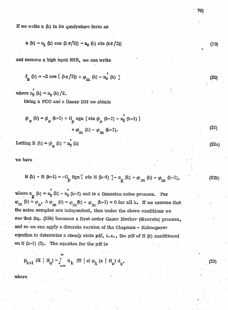
,i"
'i"
u o
u lJ i I ! i
II U U
u u [)
II 'i II
Ii
"
If we write n (k) in its quadrature form as
n (1;:) = ~ (1;:) cos Q.<;,,"/2j) - n~ (k) sin 0.<;.11 /2j)
and assmne a high input SNR, we can write
• fn 0.;:) = -2 cos [ 0.(11 /2,i) + CPm 0.,) - D:l 0.;:) J
, where 11:1 (1;:) = D:l (k) /2.
Using a pca and a linear DM we obtain
, '
¢ (It) = ¢ 0.<-1) + G sgn [sin ¢ 0.<-1) - n~ 0.<;.-1) } e e p e ~~
+ cP 0.;:) - cP 0.;:-1). m ill
, Letting n 0.;:) = ¢ e Q.r) - D:l 0.;:)
we have
H 0.;:) - H (1;:-1) = -G Sgul sin H 0.;:-'1) ]- n (k) + cP 0.,) - cP 0.,-1), p g ill m
, , whe~e ng 0.<;.) = D:l 0.;:) - D:l 0.;:-1) and is a Gaussian noise process. For
cP 0.;:) = cP , /). cP 0.;:) = cp Q.c) - cP 0.;:-1)= 0 for all k. If we ass=e that m om mm the noise samples are independent, then under the above conditions we
see that Eq. (22b) becomes a first order Gauss Markov (discrete) process.
and so we can apply a cliscrete version of the Chapman - Kolmogul'ov
equation to determine a steady state pdf, i. e., the pdf of Ii 0.;:) conditioned
on II 0.;:-1) (3). The equation for the pdf is
Pk+1 (Ii I Ho)"'-J q k (H I z) Pk (z I Ho) dz ' , -'"
where
70)
•
.JI~"," ~ .,
(19)
(20)
(21)
(22a)
(22b)
, (23)
... ·1 .;.:~
.~ '·1
'.
...
·············~I;· .. ·'.
,
-0.
.... ~ ~ ,t,

"" I
r
:J " , , , , r·' t-,,' t !J r~--, , . r
LI ~, r-~~, "', r Ll r' F-· ~,
Ll t' t
i. r 0 ~.'~ r. t.---:
L U p ;. ',~
k []
0 r' J IJ
Ij
,I
i i ,
f:.
~; II I' U ~;
jJ
f]
H '" H(O) = ~ (0) o e
PI;: (H I Ho) '" pdf of II (Ie). conditioned on Ho
qk (H I z) '" transition pdf af H (k+l) given H (k) '" Zo
Noting that ng(!;:) is independent of H (k). we see from Eqo (22b) that
the t1:'31lSition pdf ql;: (If I z) is Gaussian with
and
mean '" Ek (If I z) = z '"' Gp sgn (sin z)
2 varH!uce '" Val' (If I z) '" 2 (J' ,
Ila
2 2 "" 0" /2 '" 0' .. g'
where 0'2, is the variance af U; and cr 2 is the variance af the origillaJ. n2 noise pl'ocess nO;:). Notice that the mean and variance are independent
af the time parameter ko Thus we have
'" (IfIIl)-j'· 1
Pk+l a -, .; 21Tcr-:! -'" g
o e},.'P [- (Ii - z +0 sgll (sin z» 2/2'J 2 J 0
P g
o D. (z I U ) d • 'R. 0 Z
The range of ¢ , and therefore of If, that we are interested in is generally e [ -'IT, 'IT JoIn Eq. (25) the range is (_00, <D). A simple adjustment (4)
results ill the following
1T
Pk+1 (H I He) '" J
where
00
K (U, z) PI (z I Ii ) d • { e z
71)
•
(24a.)
(24b)
(25)
(26)
(27a)
., )
] ,1
~1; . -".1 ~
:',

.J
u u II :J
;J
U ! 1 L
, I , , i I
i I • I I ,
, .1
r
P (III H)=li(H-H) 000
and
1 K (II Ill) =L: ~2
, n= _(Xl " 21T U exp [-(H + 21171- Z + G sgn (sin z)2/2'.1 2J
P g g
so that 1"1- (II I H ) is periodic modulo 271. , 0
AB k 4"'. we look for a steady state pdf P(H). P(II)' would then be obtained as
the solution to the integral equation
71 P (H) '" J K (II, z) P(z) d
z•
-71
The search for an analytic solution of the above as well as Iltunerical
analysis on a digital cOlllPuter are presently under way. other items of
interest to investigate are mean time to slip a cycle, location of threshold,
and tiH'eshold md:ensiol1. These problems are being investigated presently.
Similar studies are proposed for the Song Audio lLnd Video processor algoritlnue.
72)
(27b)
•
(28)
(29)
i ;,
71
.
······1·.1. ':~
;;

F' , 1 ~:
~ .... , f !!",-, ~-.-- .. ~.' ( ~./
f ~ .. , i' ~, , , ~.
I L.: r f
k r F , , ,. ,., ..
~->i
J U U U ,.I
~
:J []
U U i 1 ...
r I '.1
: , I I
II
Ll
I !
I -
B.eferenqes
(1) H. Taub and D. L; Schilling, Princ!p'les of ConurmnicatjouSystems ,
New YorIo McGraw lIill, 1971 p p 326-329.
(2) I bid, pp 329.
(3) J. L. Dooh, .BtQ.chastic Processes, New York: Wiley', 1953, pp 195-198.
73)
•
(4)' Ai ViterlJi, 'Principles of Coherent ConllmIDicatioll, New York: McGraw-Hill,
1966 pp 88-89.
~~t :.I_j l_""'.;..r~ _______ _

,.
:, ',.-,
t ~ .. ~.
i. ~
~,
, L\,,:
~ &:;;:
o [1
lJ 1 I : I L I
, i
1 , i
, i
i , ,
, 1
I
Il ~
IJ .. , tr
« .......
........ :. 0
~-----~~:i~~----------------l
'4~~---
. a.
c C 0>
· , , , , · ·
.~ (!) (J) (/)
;;E '0 LLr::
0
U
>
Io
(/)
(!)
()
o ... a..
.s::: -~
-l -l a.. o
c ....
.-LL
74) .. .-.~
•
t ! , ,

i ,
II o []
lJ
lJ
U
U
U , I
i !
I I I ..
f I
I
n --.:t:. ~
~ L..J _tD
u .... I -II)
<rl o ... ... Q) ..... (J
1:1 .... 1:1 L:
U
Q)
II)
1:1 .a. a.. >. I-
1:1 C
(Xl
(\J
Q) ... ::I 0>
LL

I'
'~.' .
IJ
: I L.J
I .
~.".J' ..
i i
I r J
I I r I I
1/ I I I I I I I I I
•• _ •.• ··~~.",,,.-•• T •• '"~?".~_~, ~"..........",~. ~,,.,,. .. .,. .. ~.,,. .. ~. ~".,."' .. , "''''~, ........ , .. -"'.~."' .. ~ ..... ...".,.,., .. ""'.,.."' I" ... >." ,. -.,..., , - ~.-,,: ' ,- -
- - --,--- -_._-,----_. - -,-",-."",
1= N v .....
0 ~ ...... -S-QJ V
.... - .... , , • •
• • • I L __ ..
r---• , , • I
0 ~
76)
•
-~ ['
"
C 0
(f)
1/1 <U l-e.. 0. ::J U)
Q) .><:: "0.. U)
O'l C
.. -C .... +-m :::l
H
rO .'-';
Q) .... ;:, O'l
Li: ~",
.:\ 1
·.'1; j : -~

F' • f <,-
r ~'
" f-.
~" f ~, ~'
~' • ~ t:' ~,
! ~
" p , t t i
i !._J
, tI-:i"
U ~'
~''-k. I~
,1
", 1\ 'I"~
.;
''-'
" ;-~ If' ~:,
~; I,' ~:;; ~.
,~~ , :.-1 ,',
I ~~"
I ,I I
I',·, II ' '\
f! I ',I I ,I I
L
, '--;
I , I
I. 5. The Measurement of Light Intensity of Computer Generated Pi,ct\tres ,
A. Abst,ract
We describe a method of measuring the total light energy in a computer
generated picture. TIns method uses Cadmium S:illidc (Cd S) photocclls as
trnnsducers which convert the light intensity to an electrical signal. This
signal is th,en processed and the result is displayed on a DC meter. This
new measurement technique will provide an efficient tool to aid us in
optimally recording computer generated pictures.
B. Introchwtion
The equipmcnt used in conducting this research is related to both
communications and irr,aging systems. The apparatus gives a meaSltre
of the screen image light energy, which is the output of the video
com!munieations system. The image is gcnerpJly discrete in nat\tre,
the shape of which is approxii:nately known. However we want to lmow
the light energy so that we can optimally record the image. In Fig. 1
we show a block diagram. of the overall system. Figure 2 presents a
block diagram of the clectrical systcm that was designed and constructed.
C. QpLical System
A series of experiments were conducted to determine the optinmm
location of the photocells. It was apparent that ilia bast performance,
i.e •• signal-to-noise ratio, W01l1d be obtained by dirccting the maximum
amollnt of light fTom the Catho:1e Ray Tube (CRT) on to all the photodiodes
used. The light had to be directed to thc photocells by a method that would
not interfere with photographing the image Oll the CB.T screen. We also
had to insure that the amollnt of illumination reaching the photocells was
independent of the p03itioll of the CB.T dot and depended only on the
intensity of the dot. It was founcl that placing eig'bt photorliodes in a
circlc aro'1lld the edge of the Polaroid camera lens gr.ve satisfactory
results. A sketch of this is given in Fig. 3.
,j
77)
•

, I'.·" ~.
, , , i ,
I t.~.:"' ... ,,,.d<c_,, """-w"~_"" .,,'" ~_~.~~_., __ ._
II
o u II ,I
! . ,
I ,. ,
I,
It was found that when the eight photodiodes were connected in parallel
their total resistance varied from 500K with maximum illuminati.on from
the CRT to 5M in total darkness. This implies that each photocell has a
resistance of 8 (500K) = 4M with maximum illumination. Employing the
phDtocell manufacturer's curve displaying cell reSistance versus the
illumin:ttion, we were able to extrapol:Lte to find that the illumination
per cell was 0.005 footcandles.
D. The Detection and Meas~l):ement System
The optical information obtained from the photo detectors is processed
as follows. Operational Amplifier (OA) 1 (see Fig. 4) is a buffer to trans
form the light intensity, which is proiJortional to the photocell reSistance,
into an electrical signal, mit). During the time interval TI (sae Fig. 6) •
. OA 2 iutegrates mit) as follows:
1 TI < Ts v (t) = T J m (1) dT,
o 0
where
and
TI'" the integration period (switch S open), o
,To'" llR C. = the inte"l'ation time constant o 0 Co
T/il = the scanning ]leriod for one Video frame.
Just prior to the dump time, Tn (see Fig. 6), switch ~ closes and
a final reading of v(t) is takeu and presented to the input of OA6. The
output of OA6 is thel1 disphtycd ou a DC meter. When ~ OPOllS, So closes
and dumps the accmuulated value of vet). So theu opens and the cycle
repeats during the next scanning interval. The synchron:izatlon circuit
of Fig. 5 generates the required ,",DUtTol signals to operate switches So
and ~.
78)

r· t , l
U , f f r-J f ,: Ll ! t: I) [
r u ~ ! ~: " ,
I ! i , I , '" £:.
r L I t, ,
:' :';'. , , ,'. ~-. ! I , F !
( I
:j
I I U
u r i i I
I
i , , ,
i" , ! i
I ,
, I ,
79)
E. OVerall Perror mllUce
The desigoled circuits were found to function reliably lmdcr diffcrcnt scrcen
intensitics and complcx illumination pat-terns. In addition, the frequency
characteristics of om' processing and synchronization circuit.s arc such that
we can opcrate over a wide range of framc scanning time with little change
in performance. Thus we are able to obtain a suffiCiently good measure
of the light energy in a video frame as it appeal's on our scanner. Using
this information to aid in setting the exposure of the Polaroid camera we
are able to more precisely record a video frame.
•
I !
1
:f ,j
J J
"
:1
'1 :, "
<,

Met
er
~i
.....
~.~
~g:;
~i
~Qi
INum
inat
ion
-~~
Typ
e 60
2 t...
X H
or
Det
ecti
on
and
Pho
tose
nsor
s
Pro
eess
lng
cir
cuit
ry
Po
laro
id
Cam
era
Un
it
r ---r
---'----
--------
---V~ Y
l
I ..
~
PD
paI
L
Dig
ital
C
ompu
ter
¢l 1
o 2 o D
!t.
I ! l ~ __
__
__
__
__
Fig
. _I •
The
o
ver
all
syst
em.
• _c
o S

~',~
~ "'w~ ''
'~
-.::
7'"
,-'
"'--
--- ,
~"'< -,~--,--,
'-
Swee
p
r-,
~: ~')
.::'
:';;
-~t.
!t"'
,,-,
""~f';~4t",".:' '"
,:. -,
';' "'
,"'~
"'1"
"';~
''''
':''
:,p,-:--,..,",,,:-,,·t~\,:;,":"'·-··:-Y~-:-_:~,;y'7c"'7r~":·r','J{:::::,;;~:'~::"",~'m:
',',
,-".,
lllu
min
a'
r--------,.I~,~~
\.":~~
~9:
Li.
.l.V
ll
602
, D
ispl
ay
L Scr
een
I~::
~ I--
:::~'~
~ ,
.';.
...-
-~-
1--}
+:)
.--
t -
. C
alib
rate
d
Op.
A
mp.
Pho
to
enso
rs C
UilV
I9M
i
f'-~Siti
~~ P
eak
I
';I
. r"
t"
'7
1
I---..
1---.
~_~
.. In
teg
rato
r ,
--.. _
----
-
I -
-V
olta
ge
I ~-
•
,---
----
----
-
Vol
tage
, ,
-- R
elay
and
., ''5 -j :1 ';1 .-j I ':-i -j 'I
i'>--
·. -1 . k
?)J
I
' ,_~~~
ecto~_
.J C
ompa
rato
r'
t !l'
"Hol
d T
imin
g 1
, -
c.
-r
--._
j 1 1
,---
-.---
4r---
Neg
ativ
e P
eak
Hol
ding
Det
ecto
r C
ircu
it
-----_
.. _
----
,
Fig
.2,.
Blo
ck
dia
gra
m
of
fue
elec
tric
al
syst
em,
r----
Met
er
r
•
1 1
co
tti
.,-_c.t.
]_
Rii
iUffP"
"eew
~"Mf'i
h'! -t
"~j'
<i4h
wzW
.. ~ ......
'"-_
"'~<iL
_:x;"'
~~,
___ =
=t.
,'..
2c
!L~:
.

~¥i((r· 'F'"~'=~. _.
c.
'", c
··
1".,'
'<
,~
: ';
''-'
''~'
,,~T
T fP~~~':'Jft "'
~::'
""
!.~:
':;?
:-":
',~ '.'-vr'~"~-'·';-:!7",-:~·-:-,;~,,::::~~~·\t~:,,~~~r.~~~~T'~'f:~~J~~~~~!"r~'l!."""9~
~
'--
L_
=
Ph
etes
ense
rs
. --~ 7
/J-\ -
__
)"......-
/' /
1!i
/ 1
____
___
-----
I //
;;,
(~
I /
, A
~1
TE
Icr'
RO
NIX
602
MO
l'<iT
I'OR
.~~
'tI'a
~§
1
0
r::::~
t&
::#
S
CR
T
DO
T
/ "
CR
T s
cree
n
I /
__
~V
,". /
' ,
I \r
" i
"'C
am
era
(,
!
' .. ',l
ens
/ "
, I
'. Ie
! ...
.:-.:'
-\/-
-o~
'-\
, /
~
/ r.
/ .J
~/ /
..... ....
r'~'~
PO
LA
RO
ID
Cam
era
.... .....
.....
.. -..
. /
c
f ;~
,il J ! ~ ,:i 1 .1 .j , 1 , )~ ~ :j !
1···.··
·1·.·
! Ii
I • I '~
'I.'. 1
IJ I~
"".,
. _
_ em
of .,,,
t,,,,,,
,,,,, a
rou
nd
th
o
"m
or.
Ie...
.
1l U
L",,,;;;
.:;;::;;;
:,",, "'
." """~~~"
="~",c""
."""~~_"
""""~,,,
,,,,,,,,
, ..• '",,
'''''
. '''.~

\C
.. '~.7
Jf ····~·F'
{."9
'f~1
'
"
_-~~:c;
Pho
tode
tecr
or >
in
pu
t
""" -
';:\'Y'c~' .:;;"',:-"11'~?"1~~·-
..... 'r
.~:·~ \ ':,
:;";" "'
--'-,
",--,),::'-
'-r,,-;~"'::f\-""rl~"'? :;':"'I'~·~;:~'~'.':::~!"""~_';r,'H:":",~:'~)~'
/-/\
<~_:T~"F~r"!~~"'-
~"''
''~t
;-~~
,.<,
1M
7 +v
~_OA
3 I
+
-v
20M
Q
+v
t !\I
vy..;
..
~5.6K
~
-
H1r
';F
-1.
J:
Fig
.4.
The
p
roce
ssin
g
cire
uit
.
i--'~
m(t
) \L2
Ro=
3.9M
v¥
b
3 1+
J9M
-
r---~
C =
5."P
. o
r-
7-+
v
4b
-v
r'-~
.. vf
t)
,-._-
-, ~,---,
l-.
c--
OA
.4: ]-
I-}.j-
I Du
mp
So
-~L
OA
. 5
. -~ ~/-
Hol
d ~
6 .,
3 .
To
met
er
",-,
.. ,:
',,!!,
.-, -
: ;"
,i)-
.'.','
[-
r--'
--"
1---
co
.!fJ
.. H····· .. ··. I
;-~ '1 J 1 1 _ -:i l 1 J i~ .. ~ I ! :1 -~~
-
----C
··.1·.
....
.L ...

r~~-;:'-<H-
,["'!"
':--/
''''i'
'---'-
'~,::i, ',7f~~' ,
T-·
:':;
"-,'
--;,
.-'
-,~.
, -,'
,',-,
'""",<"
-:;'i"
~'~'7":~!:,:-~:----~,_;, i'
'-i"
,"-"
'~ :-"'<~:~:'":1~n,"'"!'~~-"7';':~'-~7~'~~:q,,:r~,~T;I~'f~:;~~'~~!"""~~~""~ ~
., ----------------------~---------------------------------
__
-t:
22
Kf
r-------'-
---lV
W'N
0;
~ T.G
5rF
Sweep~
IOv
J .:;:
1. 5
K!r
L~lN~OOl
31 +
r
'-1>1
1
OA
J, 50
r.F
T-
2.7
Kr 15
I ~ J+V
-10
M.
7. +
v
6
7 ,,+
v
:r:J.,. O
A
.~~~J.
,
_3-ff
-4
6
'. ~
~ L
1 -"'
S-!: D
ump
s ;::
.> r-
0 '!
"-V
N40
01 -'
1
50
f 1+
7 _+
v ~ l
~A
"> 6
L 2
-1"(
-Hol
d 1\
7 w
!
2 +
~A' --
S)6
r r
( !
2
~-v
-v
~ 56
Kr
Fig
.5.
Syn
chro
niza
tion
ci
rcu
it.
I····
I : ~
I'"~ ;, ~. I
co
\']
. ~
d.
I ~
j: !
I bA
"Tf" "i;
~~tl
~~"e
::::
-~~h
"/#k
~~~~
~~~~
=--i
:::;
~~~:
":-~
,;L:
;~:~
~~~~
~,~~
,-'d
,~,:_;,~
Z:~'hi:
:'~~:A\;'
~ilr~'~,
~:,:;;~J
~~;-~;~,
-~,.~,";
:Ei~," ~
~'.-,.,i;,:',,
~~,~-""._:';:'
~':"_. :~" .
'-.
''-:_'~~::

""]' ' ,,;, .. -. ""-'
Ii, ,-' .
I ,
u
I ! ! !
, I ' i
I :
I;
I i i I
U D
D
, U ~ ..
~~, "-~ ~-- -- ---
u1' •
11 i '" '" "0 • '0 ~ Ifl
<------"'--'
ORIGINAL PAGE IS OF POOR QUALITY
I
I>
"" I
'" ~
1 I>-
""
i:< '" ....
I • tl
Ql .... Oil
6h Ql
;E
,
~ I
1 A
E-< <l-.
H""' .
:E .~
'" "0 .-. o ..c: r-.
oS
i .~
'" .... o
~ o o -x-
'-'.

I
j
II L
u .U
r
n.l Testability Enhancement in Digital System Design
C. S. Chuang and S • .T. Oh
Digital syst.em applications demand high capability to
insure the correct operation of a system. Rapid real-time fault
detection is essential to satisfy this aspect of the system performance
criteria.
Most .of the existing techniques to detect the stuck type
failures require, in general, an application of long input sequences
generated by a hard core computer according to a· complex algorithln.
86)
On the other hand, with the recent advances in semiconductor technology,
the complexity of circuits fabricated on a single LSI chip tends to
increase rapidly. The diagnosis of system.s utilizing LSI r.olnpOl1ents
poses an extremely difficult problem because of the structural
comple:h.'1.ty of the cOlnponents and their lilnited accessibility.
The problem of augment;ng' the testability of a digital
system becomes the' Ctportant design criteria. Several approaches to
enchance the testability of digital system by means of redundant
hardware have been developed recently. But, they are still not
ef~icient enough to provide real time fault detection for stuck at
fault model.
One approach to satisfy this requirem.ent is to include the
faul~ detecting capability of the system from the initial stage of the
systern. design. New techniques of em,ploying hardwa1'e redundancy to
reduce the nmnber of tests to detect the stuck a.t faults are proposed,
so that the criteria of real time fault detection will be possible for a
digital system.
Some works have been done for this effort, two papers have
been published recently. The results show: two tests are enough for
stuck at fault detection of any combinational circuit implemented v;<ith

the proposed PLM's and CSI's, and four tests are sufficient for
detecting stuck at fault of the combinational logic portion and single
pernlanent malfunction of the flip-flops of a synchronous sequential
circuit implemented with the proposed PLM's, CSI's and CMM's.
Also, the test patterns are automatically generated by the systematic
design procedure.
8'7)
•

1.1
! 1 ! , '~
0/1 _I
i" :~-' ! ~" v
r I
I::' ~ , \:; ,; :~
i I 1 :I I ,
" j
i j , I
I !
,··.c.cc:··~·""··-c-,c·".c~-~,~~~,,,~.'C-~C~'7" ,...~ .•• ,.,..-~ •• "'~-. ,",'"",""' .,.~. "-r~~
EighthAsilomar Conference on Circuits, Systems and Computers,
Dec. 3-5, 1974, Pacific Grove, California.
Reprint from the Conference Record.
\)ESIGN OF gAHIJ,Y DWrECTAll!.E COMnmATIONAL AND SYNCIiRONOUS SEQUENTIAL cmcurrs*
Chin Shenp; Chuang nnd 80 Joung Oh Dc.pnrlment of Eloctricnl Enginoering
The City Colloge of Tho Clly Unlvorally of" New York Now York, New York
• Abatrrwt
Tho problem t.o rClhH'C lhe number of tento for fnult clotcct-lon in both comblnntlollt11 logic circultn nnd synchronoun Ruqlwnllnl circulto 10 In\'c/]llgntod~ ULill:r.!ng prog,rnmtnllblo logic mo(lulc nnel cont.l'ollahtc mClll(llJ' modulo, uyntcmnttc clcsJt~ nnd dcloctlon proceduros nrc descrihed. Two t(iGlR nrc munc1cnt to detect OilY stuck type fnults of combInational ch'(~uIl, nncl four tento nrc neccnnnry nnu 8uffIciont to detcct nny stuck typo fouIts of 010-mcntnry IOR'lc r.ntcs nnd the lnnlfunction of ,flIp-flops of aynchronoun 130quontlnl circuit \IBiqg II Oip-OOpfI.
r. INTRODUCTION
I!JIgltn.l syritcm nppli'caUonn demand hlr;h rcUabillty which implics un Incronscd cnpnbl,lHy to assure. the correct system opcrlltion. Rapid rcnl Ume dclc.dlon of stuck faults is oncn c!iscntlnl to lm;urc the. integrity of the. syste.m performnncc. One aspect o[ the. f))'stotn to meet theBe performance crIterIa Is to Imb .... d· tho fault del-acHng capability within the syntcm from the initial stage of system dcsl(~n. The existing-techniques [l]-{:l]to demct tho stuck faults rcquh~c, in f_~Cncr:1l, appllcntion of long Input BcqucnCGB generatcd by n hn-rrl core COlnllUlc,r flccordlng to n com-p1c:o: nlf,orlthm. On thc other 11:11111, due to tho recent ad",mccs In scm\colHluclnr t(!chllology, the cOlnplcx1ty of <rcults rabdentcd on Alnr;lc LSI chlptcnd9 to Incrcnee rapidly. The fllndlonal dillf,llOnifl of syntcmR utillzing lSI componentn po"eD it dl([jcult problem. TcchnlqueH (.t), [;,] WI~1'l1 iIlVCBt1~:ltcd in vll,rioufl (111"00-Hons lo li'lll1pllrJ til(' f;mlt dt'tcctivll hy using hardware redundancy. A IWW :1]1111'Onch iii pl'oponud hcro which \\;"11 nllnw U5 10 Ix~rfnrll1 fj\tlU detection In 1'oni limo. The follo\l,'ln" dl'flnlt.lollH nr~! 1;1trnd\lccdl (1) Input St!Il11IU\'lly: The [lcn:lll1vlty or nn Input pnllom few n logIc !{lIte In deflnod lll3 tho ntlmber of lnd1vJdunl inputs 1n the pntte rl1 cnpnlJlo of sonLiing fniluroB in tho gate.
For exnmplo, (OO) Is tho tuoot BOIlOJUvo input pnltol'n for two-input on l~:1tc Binco nny one :Jf tho input otucic .. nt-l wlll ::lffccl Its output, The most sensitive Input paltern for lho N-lnp\lt OR gate Is 00 ... 0'(N O'B). Dy extending t.hIn Illcn, the most Bc.nt..~·~~VC input p:1lte.rnn for the ordinary combinational logIc "gateo nre calahl1uhcd HS showl'lln Table-I. (2) SensitizIng Path: A path whIch propngnteo the. fuult informallon to the observable outputs. The fltuck type faults can l~a: partitioned into two claosfw by the logIc function nnturo of the elementary g:1lCB. (3) Typo I Fnult: Tho [nult sct consisting of atuck-ut-l (a-a-I:) fouHs of the inputs of on, NOB. lind the output of NA l\"D , nnd tho stuck-nt-O (s-I1-0) faults of the inputs of AND, NAND nnel the output of NOH., The complement of Type I Cnult Is deflood RR Typo IT fnult nnd they [OL'm tho complete clnns of BtuCIt typo fnulls, Il i9 fOllnd that the Typo I faulL informnUon In n cO;.-loln-, nUonnJ logic c1rcult cnn nlwnyo propagate to thc obsctvnblo outJiutu of the circuit if nnd only If tho Jnputs for nll gnics nrc tho most Bonsitive input puttdrns for tho toopocUvo gnlna. (oi) Pror:rnmmllb'io Logle Module (PI.lM}t A tnult1ple input-nJnftIo output comblnntlonal cirouit 16 defInod to ·bo D proKrnmmnbJo loglo InoduJo !! cnch of tho 10glc functionu performed by tho modulo oan 00 unJquoly BlhlClHcd
* Thin work WOB lJupporlod in port by t:th0A undor tho Contrnct NA89 .. 13940, '. / .,
ORIGINAL PAGE IS OF POOR QUALITY
.1
88)
I ./
'.
"

", ..
! ~:-
r I .. , } i ~ -,. , , [: , • L ,. P
f I," (.,
, , , f·:
r:,
~;
f ~' k· , .,
,
! I." f.-
I- t
.,
I j
[
J
I
.Y
by n Ant of con1 rol nlr.nalf1. (5) Cunh"ol HII~n:lt In\'{'rtnl' (eRI): An t-:,\('1\lllko onv,nto In whh'h unt' or In!lulu Itl Il11l'd 1111 hl\,t,11 ('111111'01 tlll~nn1.
'l'hl\ 1-I)\1\('j(h' 1111~1t~ I\ml'lhl11 of 1'1.l\t £1\1' ANO,OH, NAND nnl' Ntllt Itnh':l III II('HI't'lht,tl In 'I'lIhlt·-Il. TIlt't't' 1\1'(\
1\\1\1\,)' W:I)'~ tIl (mph·tnt'nt. 1\ tit'fllI'c>d 1'1.1\1. "'II~. 1 I1hnw~ Ollt' ne tht' ll1lp1t'~lu\I\!.nllt1n of 1'].1\1:1 (01' two-Input 1~lItcn. 'rho Jtlllll'rni n'pl"t'f;t.HlluUUll or PI.1\ht IfI-llhll\\'ll In FIr,. 2. 'rhe circuit.· constructed hy t.ho usn of PLI\1R ami CSTo hU5 thrcr. modrR of opol'ntlon: N()H'tIfAT, mndl!, TEST 1 mode nnt! '1'E~;-r 2 mode. If wo dnnolc 0110 c1I1HH oC stuck type faults which can be detected by TEST 1 modo ns Typo J f:lU11., then thts elMS lfl cqulvnlent Lo lhe Type II fftu]t of TEST 2 mode. Hllllllnrly, the TyPo U fault of TEST 1 mode Is cquIvnlcnt to tIll! Type I f:ntlt of 'fEST 2 mode and Jt eHn be detected by TEST 2 mode. So tho complete elnss of ::;tuek type fnulls cnn be deteatoll by sclUntt the c1'reuit to TEST 1 and TEST 2 modes. For slgnla stucJ\: t.ype fault ns~mmpl.lon {s-n-l,s-a-O}, nny comhinallonnl circuit with primary output observahIe call be! constructed with PLMs and CSls f'~ n5 to dotC("t the sluck type fnults wIth two tests input p:!tterns [4 ]. (J) Con1rollnbln I'Ilcmory Mo(lulc (crvrr\'l): A mClnrJ" ,
clcment with direct. set nnl! rcr:pl c!lp:.hilily whoso outputs lIl'C (,C1liVl'rtllhll~ by two CXIC'I'Il:Jlcolltrol fllf~nltln.
A f,t'llornlllll){lL~1 of CMMIA sh()\\"1\ In 1"1!~.:l. Il.!-loutpult! nrc (II nnd ill (\':hcrc fW.Y\'I'C yj • tit YI,!ICYt). Ilnd Cyleyl df'pcnds on Ow conlro SII~lwlf.; of Ill{ successor PLM :md direct set. and mr..c.t Hlf~nalG of the flIp-nop. Consider a DeIny flip-flop Cl\H.l :Hi shown in Flg.'l. Type I malfunction Is defined as the fnllure of a Delay CMl\l whIch f:Ills to propagato 0 whon D=O .. FJg.4(n) shows tlHlt the 5-a-1 of D,y,ct :1I1d Cy nrc cqulYnlent to Type J malfunctIon. Type. H malfunctIon 'is defined aD
the failure of n DcJny CMM which fal1s to propag;lte 1 when D=1. Fi~. 01 OJ) shows that t.he S-3 -0 of D, Y • q and Cy are cqutvnlent to Type Jl Inalfullction. It is sufficient to detect the mnlfuncLJon of CII-1M for fault detection of the flip-norD portion of :J scquent.i:ll circtut. The re·Jallon of control slgnnls between the conscctltlve gntos are l"howl1 In 'l'able-l11. Cy/CYi of CI'I1.i\'lls set accordIng to Table-IV. Systematic desIgn nnd detection proccdurns are dC'vclo,,~d. Two cxamp198 are useg to illustrate the proccdurns,
II. COMIJINATIONAL ClllCmT DESIGN
Consider the hoolc nn function f=b(n'+c'd)+(I.xl) I (n '+c'd)' ns f1hown In FI1~. 5 (n). Its contl'ol1nhlu cfrcullis constructed IIH f;ho\\'n tn FII~.5 ~J). AU lihe control ulg;nnls C" ChCa nrn Iwt to ho. 0 dUl'inr: the norm111 opcrntion. For IClltlllmrnt.i(ln. \'.'0 npilly tho t.wo lesls neoordlnp,- to t.he t1clt.·cllon pl'occdut'U nH follows: TE~'I' 1: 8('t CjCZClI"'Olt (rJ~ST 1 Jilodo) nnci npply
inplll tent pallern nllcd~OlOl. If tho obacn'nhle output:;: ( .... 1, then lim circuit docs nol hnyo otuck fnult of Type 1. OthcrwJHc, II hrw nt least one nt\lck fnull of Typo L
TEST 2, Sel C,C,C,=lOl (rEST 2 modo) nnd npply
89)
Input tOllt puttorn nhe<Io:oIOIO. l! the ohnorvnhlo output {~·-o, than tho circuit (\twn nut hnvu nhwk fnull of Typo lIt Olhol'\\'lm~, It hlln 1111011111. UIlO IItucl( (null (If Typo n. Ouc'u Um d1'(~ult 1'111111 1.1111111\ hvu t£ll1tll, tho circuit 1f1 gUIlt'lInh\{)d tn 1m h'tlU nf Iltuclc-IlL-l IIllri uLuck-nt-O r~\!ltn.
Ill. SYNCllllONOliS BI-:</UI':NTIAI, ClI\CUI1' WITH I)-FLIP-FLOPS
Consider ;1 two hit "hlft rIght/shift Jr.ft rogistor 0. shown In ~'Ig. G(n) hI which XI Is the serlollnpu! (or shift left, ~ is the oorJn1 Input for shIft right and X3
"Is tho shift conLrol. It is convtlried to nn coatly 1catnule circuit fiS shown In Fig. G(b). where Zm is the monitoring t ,_~ !.lUt. F.or normal ·operation ·I.'C set all tho control signals 10 be O. For testing, four test5 are appUed :lCcortllng to the dctceLlon procedure as followa:
T,"ST 1, (SdR,] =10): Set C,C,C,Cy Cy =01100 and apply Input test paltern X, X, X, =110. 'Observe the output Zm. If Zm=1, then the cornblnatlonallogic does not have stuck fnult of Typc 1. Otherwise, it haa at least one. e TEST 2: (S"Rd = 00), Observe the outpul Zl' ZjT,' If Zy Z" =00, fhen the flip-flops do not hnve 100 1'yi'£ If 111nlfunctlon. Tho disngreement ImplieB tho COl'I'oRlmndlng nlp .... nop hnR the Typo n mnlfuncLJon.
TEST :I, (Sel ]\1 =(1), Sol C, C, C, CYI Cy, "10100. nnel J1Jlply illIlll1 tOfll plIllorn XI X2 X3 ~OOt. OIJHcrvo tho out-' put Zm' if Zm =0, then the comblnatJnnallog.lc doea not have stuck {Hult of Typo II. otherwlsc, it has nt lcast one.
TEST 4, (Sdll{J =00): Observe tbe O\,tput Zy, Zy,. if ZYI Z~l2 :=11, then the flip-flops do I;ot have tho Type I malfunction. The cils.lgrcemc.nt implies the cOl'responding nip-Dop has the Typo I malfunction. Once the circuit passes thesa tests, it Is guaranteed to he free of otllck nt 1 and 0 f:lUlts of logic gatos nnd the malfunction o[ flip-Oops, Notice that the ExclusIve OR unit in the CMM is not necessary for this speCial circuit.
IV. CONCLUSION
Tho utJHzntion of l'LMs, GhtMs lind CSIs fissures that two tests enn dt!tcct nny comblnntIonal circuit nnd four tests, fo·r any synchronous sequential circuit using D-,fllp-flops. In nddiUOll, tho tr.!st pattern cnn be. cosily gcnornlcn by n syatmnaUc proceduro so us to allow fnult detection in roal tinlO.
IlEl'Ell.ENCES
1. Knutz, W.II" 'tEnuIt Test,lng nnc1 Dlngnot11s"in CombJnntionnl DIg-UlII Clrcults'\ mEE l.'rull8. on Comput~rs, Vol.C-17, 196B, pp.352-3GG.
2. Hath. J. P., ''Dlngnosle of Autom£ltn Fullum; A Calculus oro A Method", I:DM JOurnal R Ilnd Dr Vol.lO, 1966, pp. 27B-2G1.
I., . ,

0 U
, i
!
,
\ "
,
1
I j
I ,
i , , , ,
i]
tJ
~ ..
3.
4.
5.
- --. ,--,
Su, S.Y.H. nml Ch 0, Y. C., "A Now Appronch to or Comblnatlonnl Ndwurl{s", Inputers, Vol. C-21, 1972,
tho F:mlt r.ocnUon mEE '1'1':\1\9. on Co 1'1'. 21-:10.
Snlmuchl, M. ntH1 It l('1sn, It., "SynthesIs of Fault DlnirlloA:ll\ln Loltica 1 Circuits uy Funcllon Convor
R. C o[ JIEC, Vol. GG-D, !'1o. 1, 4,
slon Met.hod", Tl'nn Jnn, 1073, pp, 17-5
IlnyoB, tl, P., "On MOllifying l..ol:le Networks-to Imsubflltyll. IEEE Trnua. on Com-1974, pp. 56-62,
provo Their DJngno pulors, Vol. C-23,
fl-Inout G[l.t~ Tho " OR 0 .AttD 1 NOR 0 NAN!) 1
or,t Son<.itlve In ut Pntto~n 0 ... 0 (T; O'll)f-___ _ 1.,.1 (rIl'c) 0 ••• 0 (11 0'0) 1 ••• 1 (N 1'0
Table-I. Tho mout BonD itive input pattern of ntary SilteD. N-input clcme
~'~ Modulo Doolrod L ~ 0=0
ogle Function Whon , C"'l
PU'l AND OR PLM2 OR AND
NAND NOR
NOR NAliD
Tabla-II. Four basic programmable logic modulcG.
ORIGINAL OF POOR Q~~~
.
1I1Ipl.omontntion ,Funotion
=i~ .... PUI)
'__ ,~-t~-C(Xl+X2l+CX1X2
C "
Fig. 1. An lmplcmcnt~tiQn of four b~oic 2-1hput PLMo.
z INPUT
1£ ~L------m~----.J
(control signal)
X • --z ~PL.Ml - • C .
z
Fig. 2. The general model of PLM and symbols.
90)
•
I
r ;
I . ." .",\
i ,
i·,
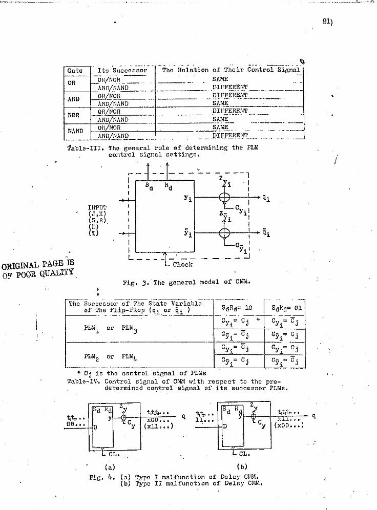
iU
lu ,
~:
.:: .. ~- :"":.~:.~.~,~.:.~~::-:--,--~,,,..,..,~ .. ~.~,.,-, <~'~"""~' .-.. ~.:,.,. """"''''',,",' "'" '''''''',...".........". I..........,.~ ---------- ....
... - -_ ... - . -- _. - .. .. Guto Itt1 Succonoor Tho Relation or Their Control Si[lnul .. ---
_pH/NOR ~=.-OR - -' . SA
AND/NA~_. D1 .. . -- -
MIl 1'I'E1mNT . __ ._.-. _ ..•.
AND ...Jl.i!L'NOR - or _ .. -MiDL'NAND SA
NOR ORiNOR DI
ANDiNAND .. . - .. ---
SA ...
ME='== __ _ l'I'EREN'f
NAND OH/NOR SA ._-_ .. _ ..... RI
ME -.-_. - ---.- •. ---f!1£~WL_ ... ._.... .....J -_ .. _-- _ANDiNAllQ __ ... :
l'able-III. The [leneral rule 0f determining the PLM
,
,. "
ORIGINAl, PAGE IS OF POOR QUALITY .
INPU" (J,K) (S, R). ( lil) (T)
. , ,
control signal settings.
1 I L __
-z - --, i 1
I
Yir---~~--~:-+qi
z- CYi 1 Yi I
I :5'i I---f-R--~:- qi
C10ck
I CYil __ ::.1
Fig. :3. The general model 0:r CMIIi •
CYi~ Cj CY'~ OJ ___ ._ ... _. __ . ________ ....I.. __ -=-___ "-_L .. .. C j is the control s~gnal of' PLMs
Table-IV·. Control signal of CMM with respect to the predetermined corytrol signal 01' its Sllccessor PLMEi.
tlt~ •• oO •• t
~d HQ "1 tct..tJIJ • " Y '.f c
Y xoo ..•
D (xll ... )
q tit:. ••• Sd ltd ?
l~ ••• Y '{ C
y D
L CL. I.. CL.
(a) (b)
Fig. 4. (a) Type I maHunction of Delay CMM. (b) 'fype II malfunction 0f Delay CMM.
"t1t.1t z •••
x~~. H
(xOD ... )
91)
, i
q

F'" ~ 'L , ,
~.
r !
l j:,. 1> W I' .' t ~. , , 1-i i ,
~ , , I , I j
, t;
~;' , I
~ I I
J r,'
r I " ,
" ~
J r C;., ~";' " p f::<: t,t'
;,~
C1.
Xa
c
d b
a=Cl--+-[ e
d=Ca--!-"-' PLMJ 1 b=C a Cl ):>---~--$--c-J -"!.'---'
( a)
(b)
Type I faul ts=[al , bo ' c1' dO' eO' go' hO' 10 i jl • ko ,11 , mo ' nO ,Po' fo] Type II faul ts=[ao ' bl , co' dl , e 1 ,gr' hl' 11' jo' kl,lO ,ml , n l , PI' f l ] Where x k = thp. lille x stuck-at-k (k ~ 0 or 1)
Fig, 5. Combinational circuit design example. (a) Original circuit. (b) Easily testable circuit.
Yl Ya Sd R Sd'R ' Yl Ya D D
ZYI IiJ Z- D -k~ Yz
j Yl Ya Yl
Cy c-y- .-J
OJ.. ..-
( a)
(b)
Type I faults=[a1' bl' c l ' dl , °1 , £1' gl' hI' i 1 , jo ,leO ,ll,ZmO
]
Type II faults=[uo ' bO' cO' dO' cO' fO' £:0' hO' i O' jl' leI' 10 , Z'"1]
Fig. 6. Synchronous sequential circuit desl.l\n exomple. (a) Original circuit. (b) bsily testable cIrcuit.
f •
£
92)
I
; I
., ,
I 1 , 'i 'j j ;! ,
'- ) j ., , 1 1 -i
Ii ~'''1

I
~ ~ .
f , , ~-'. ~,-
r r , t \' , , , i·-r ~ ,,~
• t 1:
'" ! r
I
i-
,
-,
"i Reprint from IEEE Intercon 75 Session 11 lR "---- ._. ______ • __ .. ______ ~._ - ff .- - .. _------
11 "'-!
1) L
i
U I
I i !l I l U
i I . , I ,
:
I , I: , II . ~ . r,
f,
iI',
'1"·:S'I'A'"I.ITY I':NIIA NGEM EN'" IN IHnlTA I, HYHTI:M IJIWf(lN
ChIn nhmll~ Chul1nn: l11ul ~~ ,11'lInr~ rlh JlcJlllrt,mp.nl nf Eloclrknt 1·:lIr~'IH·(!rlnr.
Tho City CoHcr.o of '1'110 City lInlvcl'lIlt.y of N(~w York Now Yorlt, Now YOl'k
Al1STIIACl'
S('\'C"';11 nl'llt'o;1(:h(1~ t.o l'l1hnnC'o Ihn II'~tnhl1lty o(I'h~llnt aj'!'tt~m h:: nH':I1\l'< (lC lTdmul:lnt hal'liwlll'e hm'll "cen ))1'0-posC'd l'I'C'C'nlly. II:'o.l A He-\\' W;IY of ("IllJll{lylnf~ hnrdwflt'o rctlunrln1l{'Y 10 t"C'IIur-u the number of tCRlr; for fnull deice ... lion In holll combhwllcmnl :lml nyncht'01lC1tlR ncqucnUnI cil'''
cults I::; In\·(,f,tll~nlerl. All npprNlch Is IH"C!;(:ntcd fQr utili ... 7.11lJ! !ly~,tcm:lllr. TI'{\undmH'Y to nlmpllfy IIc::llm worl(, MOtlch £()1' PI.t\l Ipl'nl~l":1'mm:lhtn lOf:lc OlOltulc) nn€! Ct\1M (control1:lhhl ntC'1Il01'Y l11O!tllle) IIn~ d{~pi(.~1l-d, ~yni('mi1Uc
dc!'tir.n :lIld {"'if'dlnn ill'O('~dllJ'(~~ O1'r clcncl'lbcd, ,Ur;lnrr, thcRe pnU't'(itll:l'f:, :1Il (':1!l11,\' i (,,1 nl11c d l"{':l1! l f fnt· nl.uc1t fnuHnl (':111 hf' tlronll:nr'd. Tn ('nnll'll!lt tllthn onl'lIrl' l'erouHn on (null c1l'it'c'thl\l In IClJ~tc {,Irf"!!, 401,·1\ two IN;!iI 111'0 nODdod to det.f't't.III1Y nt\u'lt fnllll}: (If C'Cllllhlnlllloll:d logic cirmllt. Foul' I('slr; nrc 1l(.'('l'RHnry IIIH! fHlfTI('"ll'nt 1(1 detect nny stuck fnUltfl of t'iC'IlH'lltnl'Y lo~ic r,nl£'!t Ir'ld the 1Il1llfnnctlol1 of nip-flops of !i)11Chl'onou}: Goql!cnt1l1~ circuit using Dslny nip-flops or Trlg[tcr Olp-tloIIS.
If n log"!e J!nt.e cnl\ not 1X'l'fol'1l\ th<' c\{"!lln:!-<l lor,-Ic functton with l'c!'prct to t.he Input p:IU('rn nIlP1!cr!, then thero CXI!\tR r.nlll0. PCI'llHHlC'II\, r:lUlt.~ In I.hf! \ol;lc r~:1to, ThcBe por
'mnncnl fmllls :ll'C ddinC'd no ntlld( f:\II1t.. Thc studt fnull enn ue elll <'A'lirl7.cd Into two t.YI)(lI1, Owl Iii, stuck nt: logle 1 (6-0-1) rmel sluel;: nL lor,-ic 0 (fl-Il-fl).
Consld(!r n two-Input liND 1~:ll,e(. There nrc four possible hlnn]"), Inpl1t p:lttcnu; (00, "01, lO, 11L Some Input fnllure:! will not cnu!w (h(' olltputlo chrmf,c, I. e, , they
• nrc m;wlmd, For eXll'r:'Iplc. If 0010 uned :\I"l lhe Inputn to £In AND r.ntc, the output wtll be affected only when both inputs Bluek :It 1. nnl! nll the other pODRlblc st.ueT;: failures wl11 be mashed, We Inlroduce lhe scmJllIi'i!,y of nn input' pattern to n r,alc to cln~Rlfy the. pnU:crn accordIng to its nblllty 1,0 nvold fnull m:mklnf,. .,
.,
The rwnnlUvlty of nil Input pntlern to n ~nto IfJ doflned os tho numher of Incllvltiu:11 Inputn in tho pnttern cllpnblo of BCllf1.lnr, fnlllll'Nl In the r,:tlc.
If we :1pply lhl' Input pnlteJ11 01 to [111 AND r~nl.c., then' only thc Input "0" slucJ{-:1t.-l wlll Hfket the output. If we npply Ihe lnpul p:111P.m 11 to t.ho AND ~lIta, than nnyor both "1" nt.llC'I\-:1t.-O will CilII9C the ch:1I1p."C! of output. lieneo tlhc mO!1t. :!t'n"Hivc Input pnUcrn for lhe AND I~n.to 10 11. Wc find tlwt 1I1f! Infl';1 Ill'IlHItI\'C Input paUcl11 for :111 N-lnput AND "nto 1!lll. .. 1 (N JI~ll by l!xlendltll! tho rlC!flnfUon. Tho moat Elcm;I~I\'e Input pntt.el1lH fot' ordlnnry'011. nm! NOR r;oto6 nro till zero Il1p\ll., :mtl for onilnnry AND nnd N,\ND ~nlo nrc till one InpIIL For Exclllllivc-OIl nnd Eqllb'nlenco f,lItoD. nlllhe po:;nlhte Input pattcrnu hllvo cqunl Donnllh'1ty.
." Tht II wnl'lt Willi !Hlppnrl.cd In rmrL by NASA-Boontol1 undor. tho NASA COllt";"!lel NAB 0-13940. .
ORIGINAL PAGE IS OF POOR QUALITY
·C.<-, -, 'I' . I
A pnlh In rlefhll'd an fH'nnI1.l7,lnr: lmlh If fho (nult Inrl11""lllRlion en" pl'nJl:1I~III(' IIlonl~ Ihe p:lt.h tn tho ()hnl~rvnhlo otllptJla. The IItuelt l.\11f'! r:mlt nr (Ill.\' comhlnnUnnnl cIrcuit crm ho ll:1rtlt,lnnf'd InUI two IfIHtlnct c1:"l!IHCfI rtccorlilnr, to lho logic (utlcth," Jl{:rform~d hy the elcmentnl)' r,nt.c. One c1:Hln 18 the El1uck-nl-l (0-:1-1\ fnullr, of C!ln-In o[ nn on or NOn. r,ntc nnd f:m-out oC n NAND s:nta nnd the ntuck-ul-O (o-n-O\ fnults or (:ll1-ln of nn "NO or NAND gate nnd fnn-oul of n Non r,:1lc. '1111A c1mm la denoled nB Type I [nuite. Anolhor cl:1!\r; 1:1 the complement o[ Typo J (nulln nnd 10 dcnotc.(\ tlB
Type Jl fnu1t.n. Wo cnn then conclude Lhc following theorem, . . I I
Thcot'(~m 1 . J
Tho Typo 1 fnull fnformlltlon In n comhlnnLionnl10gic clrc.ult nlwllj'a propnr,ntor; to Iho obnorvnhle outPUlR of tho circuit If find only If lho circuit topo1oftv 16 llrrtmgcd In Stich n wny Ihn!. lho bp\1to ior nlllPltcr,\ nt'c tbo most scnaLtivo input palterns fol' the rcopectlve gates.
J
1. Sufflclenl Comllllon If we usc the moot BertelLI,,!:! Input pnUcl"w liS tho teHt. lnpl:to, then any fJlllClt at 1 0:: {j
[milt of 'l'ypc r f:mHs wl11 !Iltel' tho oulpul or the rrnlc. 'fhlfJ w1111n turn nffed the output of tho rmhncqllent'!J:1lGa COIl
nocted to It by chnln procC!'w, flm1 the (:lult In(orillnLlon of Type I wfll evcn!,uaily pro)'1aL~lIte to thu obool'vublo outputs.
2, Ncr;ocf,snry Conrlltloll Since the mont nt~nflillve In ... , put patterns wlH not mask nny aet of fault InformnUon in . the Typo I faultD, tho nccesRlly 113 obt;louB.
, In tho fol1owfng dlacusf3lor., let lho lIno 'X stuck nt tho
logic vulue k bedenolcc.1 liE! xk
(k=O or 1).
E~n.mpl0 r
Consider the clrcul.l shown In Fig. 1. The circuit enti!lfiofi the condltJons of theorem r becmmc It if! posDlblo to find n t;C5t 1nput. pallern such thllt Inpuls to C\'ery gnto fIre mont ncllHiU ..... c. When wo npply nn input pattorn nbc(\cfw.:;1101001 to thIs c1rcuJllmd observe z,=1. In rCRpOnaG to Ule Input, then the cIrcuit docs not have T)1)O I [nulls, whero ~rypc I fnultJ:;:=I~o' bO' c
l' dO~ e1 , f1 , go' 1t
1, 10 ,
, ( J , It t 1 , z On lhe olhc~ hund, if 1.=0, them ('xlnts I' 1 0 Po •
I
n1. }cnllt ono l'yne I fnull. Sln'lj}nrly, If n new cJrcult 19 j:tenernlcd by 1ntcrcll:ull.rtnn on Lo AND, nnrl Non to NA~m, 01' vico vernn In Lho elrcuil of FIg', 1, wo cnn detoct tho complomont of 'I.'ypo 1 fnuHf] o'r lho orig-lnnl c!rcuh (rom Iho now cl-rcult wIth tho complement o[ tho Input pnttern uaod for dctccLinrr lho 'l'ypo I fnnito In tho orlf:;lnnl circuit. Thin
. structu-rnl convorolon f(lr lcnLing enn ho porformod lIy mel!ntl or tho prognunmnblo logIc modulco (PLM) •
I,' ,., " ,." I; •.
."
• 1l!J.
, J ;
i l
'_:1
i -,1
j ··1
1 ,

, '!:
J 1]
, I i. J
'j
u [J
[J
[J
il
i I LJ
I r I I • L. I I
LJ 1
jO
In 1 -" ,
~- ~h. -L._- l\ --". ORIGINAL PAGE IS c----.. -L....-''/t___ OF:POOR QUALITY
<1_._ .. ___ . __ ----.-L)U---. <>--._-.. --- --------I_) 11:._.
r----..... -.. -----.-----\ '')'t L __
r,--.... _ ... -- --;. --... ----)1:.... Fig.
A muHlpltl h\lml-~Inglc C}Ullll.t c01l1lJinnl:ioll:J1 l'll'cult ts cldln('d ltl 111~ :. Ilt'llf~t'nnm\nhh' 1(1l\lt' mOlllllt~ If t~!ldl of tho lo~lc funt'll{lm~ Pl'I'fill'1lH'd hy lht' IlH1du}l' (~n" 1)() uniquely Upt:!ClflL~1 hy n gl.'t of control s1!.~nals.
The specific lOI~lc fUl1cllons of PLM for AND, OR, NAND nnd Non gnlcs r.,~·e dCSCl'UH!d In Tnble r. There nrc nutner ...
. ous wnys to Impl<':mcntlhc desired PLtt. Fig. 2 FihoWB one of the 11lIplcmenln"Ion of PLM1s [or lwo-Input nnd one-oul ... pul glllcH. The 1~C.\IlCt'nl rcprcsenlnliol1s of PLM' s nrc shown In Fig. :1.
x
y z
z= cxy+ C(lC' y)
x y
.~ Fig. Z
v 11/.1
PLM I PJ,M Z
~~;·~z - "'!"_'-L!..J j .-
; r ~~z
PLM 3 PLM4
Fig. 3
Gor.oHary
Any sluei, fuulllnformnLion In the eomhlnnlicmnl1oglc network wl11 pr()IHlI~nto to lhe oil80rllnbl0 oUlpuls If nnd only if lhe slrl.clurc or lhe nelwoll!i: satisfies theorem 1 nnd all tho gatos aro intcrchnngcd with the suitable typos of prQgrammnblc logic modules.
94)
'nhc dcteellon of Type I faults Is obvious. The uU1I7.ntion of programmable logic modules al10ws us to tie rive a simple test pattel'll for the delection of the t:omplement of Type I f:mlts by setling 1:11e control s'ignals for the PLM,I s. In olher . words. any ShlClc type faults can be detected by n sIngle inpUl pnllc.l-1l and Its complement.
The circuit consll'lctcd by the PU.la hns three circuit modes, -t. o. , NOHT'I--tA L mode, TgSl' 1 mode, TEST 2 mode. If we den ole the clusB of stUdt type fault that cnn be detected by TEST 1 mode us Type 1 fnults, then It Is the Type n faults of TEST 2 modo, so it can be detzctecl under TEST 2 mode. This implies that the complete stuck fml.ll class w,Ul be detected under TEST 1 modo anel TEST 2 mode. In the fcillowing. we let C
1C
2=OO indicate NORl'vlAL runde, <?lC2=Ol
inclitmtc TEST 1 mode and C1
C2
:::10 indicate TEH'r 2 mode. r f
where C1
C2
arc the control signal or its cQrrespondlng
P,LMs. Notice that the faults nt control signal !l.l'e equlvn~ lent to the corresponding fault class Ht testing.
Fixnmnle U \
ConA'ldo\" tho comblnntlonnl circuit for z = (XIX2)'(X~x3)'+
. (X1
X(4)'(XzXa.)' nF! shown in Fig. -1 (n). We usc 1110 PLi\-J3 In
plnce of eRch NAND gllte Dnd connect the control siKlmln us uh()".ll In Fig. 4 (b). For normal oporalion. Bolling C,C
2;.eOO
(nol'mnl modo), nU the PLM31 B funellon lUi NAND gRlca.
) L I
'" 1
~~2~-C-.,,'-"'3,~:"'~j;,',;;.,:~.~~::-,~_-... 'k~,,"",,;;1i.,ii,;;;;;.:c;;:;;"0iwii;;....;,iiiy"'~;i;J=;~j.;c:,;i:'_'o,~::f}"',c:d,1j.::, '.: •. : ";i"",~.i"'·:;· ..... . ....... ~.::I·-,-;·.: ..... )

P"'''' , ., I t •
I w
f:
f ". i i .•
r f
, il ". lJ t i f' U ~~ . t ~. ~M'
.-
0 r. (c'
~~. '': ,.
lJ Ie:' r,-,,1-k}c ~
W ,-~ "','f. c""
ii i;
LI L,_
0 ,~
I t;-,
C'
.,'
fj ;,
~. i I I
)7 l I F-:.
;,(,
0 l ';-'
Itor ll'~llllgl Wl~ I;;l't (\(;2;-10 ('I'EHT 2 modf') nUIl(x1x:!x
aK,1)'"
(0000), COIH1(>(luclll1y, n1l the g:llc~ In mId level he come NOn nnd nUlhe r;nlNi in even lQv(~IIH.lconlC' NAND. If 1,--0:0. wo then Imow Ihnt th('1"0 exIsts nl1<~Ol$t. one Type It f;ltIlt. Then we sol CIC~I"'Ol (TEST 1 mode) :md (XIX2KaX4}~(1111). Now
nll (he r,nlcs In oeltl Il'..'vcl1wcoruc NAND' 9 amI 0111 the nates in even lc"cl NOUi s. JC 7, ... 1., Lherl.'! c~Jsts nllcnst onc Typo I fault. We ohsc1'vC that the Lest Input seQuence Is short find ensy to produce Jf the> ('ombln:lticlIlnl nctW(lri( 19 confitnlctcd to sntl~fy the condilions of Theorem I.
(a)
(b)
Fig. 4
z
E~l'ep! fnl' II I'c~tl'Ictccl cla~fI of r~II'Cllh~ Atlch liS the onc JIlust.)'nte<\ In I':xnmple Uf, we erm (!01Wet't n eh'cuJl to n
" 8p~cHJcd !It.l'\Idlll·t.~ which ",HI ''':If-tRfy the j'(lquJrClllcnt of Theorem I du,t'ln" the tCRLln~ hy llrojlCl'ly setting the. control sJgnals of PL.Mst. The choict! of control signnl sctUngs for R glvcn ck(:ult is thcrcfol'e In'portnnt. The telntJon of control signals between I:he consecutive gates a'1'e cstllhlished as shown in Table II b!lseri on Theorem r mld its corollRry.
Gate· Its --"-'
,')UCCCSfiOl' Helation or Their ContTol Signal
on OH/NOH --~?'\_T]2£_ ... __ ~ -ThD/NA~ Different
AND OH/NOR I Djf[(~:rcn_t_--,--1----'
ANDlN1\NP. I Samc __
NOR OHINOH Different _~_NIJ/i'!!.!-N~_ Sain~ ___ ~
NAND _ O~{/ ~.9J~ I Same AND/NANIJ i Dj,Hcl',ant
-,
Table /I EX.llmplc HI
Con::drlcl' the .Uooje:m C'.'Q)l1csslon z-=x'y'+xy as shown In Fig. 5 (il). Jl Is imposAiblo to construct the c.lrcuit. to sntig. fy the. connect lOll l'C'qllI l'cmcnt" by the lcchnJque of Betting control fJJ~llahJ. 'l'hr. only \vny La solve this prohlem Is to apply n contl'olJcd BIJ{l1nl JU\,(,:rlor (CSn III Lhe proper points In tho drcull to m:lkl~ the drcuit fw!lr;fy Uto contlllJona of Theol'em I", TIm GSI Is actunlly nn Exclusive on gate In
¥ H' . "!1' .. ',. t""T""I"'t/"'~
"',., '95)' -,
whld. {Inc of (ho InJmlln URNI an Icw" cfllllr·,j "Ir,na!. Sf) the circuit cnll I1f' r('('on~t11lctcd hy usln" PLM'H nod esr an 5ho\\11 In FIE'. 5 (h).
Fot' nOl'mnl opcrnUnn, We Act C1 C
2Ca='OOO, For·teRt~ng,
we set C1
C2
Ca:Oll wllh (xy)"(OO), nnd lhen .ol C
1C
2Ca=lOl
wilh (xy)=(ll).
" y
x y
(n)
(b)
Fig. 5
• z
I z
In our subflcC]unnt discus-Rlon, nn tnput vnrlnhlc of the circuit wJ1l he fJnld to bc n prllllnry Input If the varlnble.ls
. incJuded ill Lhe minimal ex-pression of at loast onc observable ctrcuJt output.. We then concludo the followIng corollnry.
COl'oIlnry II
Given Imy comblnnLionnl cj rcuil. If erich olmcrvnhlo output of the clrcuJt enn be rcprm:;cntcclils nn explicit switching function of ci-l1cult Jnputft, nnel ench clrcuil Input vnrlnblo is n prlmnry input, then the. circuit cnn bC'conHll'\lctcd with PLM' 8 find CSI 60 ns to detect tile studt faults with two teat input pntterno.
n. SYSTEM J\ TIC DESIGN PROCEDL'RE FdR COMl3INATIONJ\JJ ClllCUIT
The follOWing definitions Ilre Introduced to facilitate the dIscussion of the systematic dcsib'll procedure.
Predec.essol' gnte
A gate G1
is called tho predecessor of a gate Gj
if the gate output of G j is ono of the Inputs of the gate Gj' On the oth~r h:Uld, 6
j Is t'hc successor of G
1•
Level of gate G
Let the Ic<:el of gate G be deno~ed as L(G). Then L(G)~l if the gnte olltpul of G Is Ute. prfn1f1ry output (observable). Olhorwise, l..(G)= Lhe muxlmum level of the SUCOCf:lSO!S of G+ 1.
Consider the cIrCUIt shown In Fig. 6, where Zl Z2 are
primnry output. Then L(G2
)=I.{G4,)=1 because their gate
outputs n'fe prJ.mnry outputs. L(G3)=-I..(G4
)+-l=2 nrid 1.(01)=
mnx [1.(°2), r~G3)] +1=2+-1=3 Ilccording to UlD definition.
lIiJ
~'.
--.

:J
r.._
,"," .1 ,,'
~r
IJ
0 ,
0 II/J
[J
(al
b
c
d
96)
An nlr,orllhm of the nYAlcmntlc dCIlJnn prococlure for the cnmhlnnUonal circuit lit :;Gilc-.;:f,Rl from lhe property of the proposed PI.lM' fi nnd the Introduced ;leflnfUona. Tho flow churllH fihown In Fig. 7 nnd the dctalt<1 of the proceduro arB descrlhed below.
§yslcm:ttlc design procedure
step 1 Fiml nut the level of cilch J!nlo of a given comblnationnl circuit nnd reconstruct the clrt:utt to n controllable
. circuit by u~lng PLh-t1, PLfl12, PLTlf:l and PLM4 to rc"plncc the Ah'D, on, NAND and NOn ~nte respectIvely. Denote the conlrol signal of the predecessor DS CP nnd the logic "alue of the primary Input nR PI Bnd the reference control algnal DEI ns.
Step 2 l.d 1",,1 nnd J ... lho mnximum leval of the circuit nnd Ow control slr,nnl of PI.lMl/PLM;) In lcvel-l be C, and thnt of PLM2/PLM4 in lcvel-l be C
2' wllere C
2ia the com-
plement of C1
, ,; (
. e-------- Step~ PJc1t one Jnput of level-l which Is not picked yet nnd truce bach to its predecessor. If tho. module from which the Input Is picked IB PU.u/PLM3. go to step 4. IT the module from which the Input Is plcked Is PL)'12/PLM4, go
level J level Z level I (bl
Fig •. 6 to step 10,
l§T.~tiJ Ifind out the J'c\'cl i(:ltll replace the gate with the prope.r PL~f •
Let- F= 1 and J - the lil[:ner.t level nnB
GE IS ORIGINAL PA OF POOR QUAL ITY
CS oC PLMljPLM3 in levcl-l-C1 ~nd
CS of PLM2/PLr.H in level-I:: Cz. where ,CS i!l the control !lir,n;,.\ •
"----Irck On<':: input o! level_l and trace back to its predccel!!!lol".
YES In_the module PLMl/PLMl? NO 10
I Le.£nS::-Cs of this module. YES s CP d-e£inml or not? NO
LWIi~t 18 the. prcclcc_c_slI<;>.r, 7, What ii! th¢ pYed_eJ:;cDl',t?f 'J
~f"~ "U"\,':'" .. ~ ,.J,~ PLMjPLM' prlm"r lnpu,
CP~.S. NO ICPt.s?),!.}" ~JlS? NO .~~,m;'1 lAt CP= RS. Let PE", -ltS.
YES/ Net YESj' . t t
P
In!lert CSI tn Itcri!:11 with 'thill .~n.p.Hl_ •
. S In each input tif l"evcl·l picked or not? NQ
ISTOPI YE.t;, ,....t:ES
"'[)J ? NO ,I:" 1+ 1
NO
PLMZ/PLM3
Fig. 1
•
I \
I
:i

.'
,I f I U
u II iJ
. : . l
Ll
o
(1) PLM2/PLM:I. ch~ck "ls CP=RS'j" rc yea, go to step G; otherwise go to step [j.
(2) PLM1/J'LM.l. el,eck "Is CP=llS?" If YCB, go to step 8; otherwJse lXo to slep 6.
(3) Prlmnry Input, dwelt "Is Pl=ItS?" If YOB, go to step 6; otherwlso, go to ·~~tep 8.
St.ep.6 Insert it CSI in serJes wIth this input. Then go to slep B.
• Stop 7 If the. preclecessor fs:
(1) PLM2/PUljI3, Eel Cl' to be tllO complement of ns.
(2) l'LM1/PLM4, set CP to he equal to ns.
(3) Primary htput, set PI to be the complement of RS. TIler.' go to step 8.
~ Check to Gee whether each input of the lcbel-I is pIcJi.cd or not. If yes, go to step !I; oUherwise go bnck to step 3.
Step 9 Chcch nls I larger than J 'I" If yes, the procedures are completed; otherwise leL 1=1+1 then go back to step 3.
Step to Let ns be equal to the control signal of this PL1Vl2/PL1\l,1 module. Then ('.heclt t.o Bec whether the control aJgnal of Us prcdccessor.ls clefined or not. If yes, go to step 11. Otherwise, go to step 12.
Step 11 If the predcccssor is:
(l) PLM2/PLM3, check nls CP=RS?11 If yea, go to step 8; oU~crwlse go to atop 6.
(.2) PLMl/PL1\'N, check Ills CP=RS?11 If YC'.3, go to step 6; otherwise go to step 8. .
(3) Primary input, check 1IJa P1=RS?11 If yes, go to step 8~ otherwise go Lo step 6 •
Step .L2 If thc predecessor is:
(1) PLM2!PLM3, sctCP to be oqunllo ns.
(.2) PLM1/PLl\14, sel CP to be-th(~ complement· ofns.
(3) Pdmnry lnput, go to step 8.
FAult c1~l"ection pro("{'chl r.c
set PI to be eq~lRl to RS. 'l'hcn
C
Fnult dctcdloh In'OCORR for th<} trRlls1nlcd circuit ie ouay to follow. Th!! lCfll Input l"IIU.crn In nlrCJ1~dy r,cnerDLcd by U10 dCflJE:~n proccdu '·C. Two tests cun detect ltll Druck fnuIta (Typo I nml Typo I,'"\~
97)
'I'cn.!:...! Hd C c2
c, - 011 flnct" nppJy the corrcnpondfng tent input pnU.cnl, d the o\)Acrvllblo output of PLf.l1/PLM2 1s 1 RIal Llwl or PLM:l/PJ.M4 180, th(.'ll the clrculL doct) not hnve ony 1J'ypc I fmtlt. Ol.hcrwlflo. (t has nllonst one.
Teat. 2 Set C C2
C, =101 nnd npply the corrcspondIng toat Jnput pallcl'n. tr\hc ril)servnble output of PLM 1/PLlI.·t2 is 0 and thnt of PLl\1:t/PL1\l4 ts 1, then tho eircuU docs not have any Type II fault. Otherwise, It has at lenst ono •.
• Once Lhe circuit passes these two tests, it has guaranteed
to be free of ~tudt fnults, lhen Bet C1
C2
Ca=000 to pCT[orJ'll Hs normnl opcrntlon.
b
c
c ,
l
g D-
(a)
)------") , ./
I
-z - 2
fo CZ.~----i
g=Cz~---------------~--~
level 4 loyel3 level Z level (b)
Fig. B
Consider the circuit shown in Fig. 8 (a), where z :':" nre the observable primary outputs. We first define the tevel of eAch gate nccording to lhe definition, then the ci·rcu!lls converted to a easily delectable c!·rcuit as shown in Fig. 8 (b) by applying the system nUe procedure. The lobel for cach line 1s used to define Lhe Type I fault and Type 11 fault. The input test pattern (nbcdcfg)=(-Cf}C2C1CIC2C2C2) is.genernted. Two tcsta nrc .[lpplied as 'f ollow£;:
Tent 1 Set C1
C2
C3
=011 nnd npply Ihe tcst pnltorn
(abcdc.fg)-==(1100111). ·II zl z2=11, then the ci-rcult does n.ot
l:~nve tiny Typo I fault, where Type I fault:: fao
' bot °1
, d1
,
°0' fo' go' hot 10, jo' kl , 11 , rnO' nO' zIO' z20J. Oth3rWise, it hns lit lenst one..
T~nt 2 Set C1 C2 Ca=lOl and npplytho tOGt pntlern
(nbedofg)=(OOllOOO). If '11,2=00, then tho elrcult doon not
hnvo nny Typo II fnutt, whore Type n fnulL="[n1
, bi
, CO' dO'
1113
:'

;.~
I ~
, .
I j
I .J
, i : . .1
.~ . _I
u II n i]
0 II
'\' fl , r.1, \. 11, j1' I{O'
",hiC, It lw~ nt lens! one.
1(11 1H1 , ll' 1.11 , 7'21 i. Olhol'
•
t-::\{'h fllp-fll)!' h:1S ft~ o\\'1\I1'lIlh lallie. Tn 'ddl'l'lillne Uw nCL'tll':lCY of flip-f1()P. it Is nol. TWt't'~HHll'Y It) find oul where t~ '\T(ln~ lnshl" the flip-flop. The im))(H't:mt asped is to know whcthC'r 111(' flip-flop dll(,S ftlllction PI'opr'}'l), nccordlng to its dC'~ir<.'cl truth Lnblc or not. If the nip-Oop enn not function t'01T('Ctly fot' ccrln.ln cxcibllon, then we fioW that the nIp-noll haR mnHullcti(lU. Tho malfullction of nJp-Oop enn he clnsfdfkd, In I!Cncrnl, into four cnlcl~oricfl:
1. 1"'Jll~ A mnHill1e!lOll tflllw nlp .. flo}) fnlls to l'cnlnin nt Us prt',-iOUf; st.:11 t~.-
2. Tv))!" n m:dfnnctiQu Is the flip-flop faHs to chnngo its previous st.nle.
:1. '1\1llt' C m:ltr\l1\d Ion Js lhe OJll-OOp fnJh; lo rosot to o stnto.
4,. Typ!' n 1,wHunetion Is lhc flip-flop fujIs lo sct to 1 stntc.
Conl,icier n D .... fUp-flop, it will only h:wo Type C fmd D mn1fullelinn::;. Type C lllntfuncUnn is ciluscd by the failure of fnilinl~ t.o n.'sd Lo 0 stnte when D-O, Type D mnHunction is c3\15c(1 by Ilw fnlll1rc~ of f;li1in~; 1.0 !wt to 1. stnLe when 1).-
The 'I'-rlJp-Oop wjlJ only have Type A and l11nnJfullci.ions nccorcling to its tnllh lab Ie. The.J K-Bip-f1op wllllHI\'c all of thc four pos;:;ihlc mnJfunctions. rf the nip-flop docs not have the m;llftln~-:linns dcscrib(;)c\ :lhO\'c. then il is cnsu~'cd to function properly limIer nIl the pOfisiblc jnputs unless there eKh,ts il intermittent (tr nnsicnt) fnuIt inside the Dipflop.
IV. SYNCllHONOUS SEQVENTTA L NETWOHK
The difference botween sequcnt:inl circuit tlnd combinational drcuit i:=: th.lt the. scqucnUnl circuit cantnins memOll" clemonts in nddit:ion to the comi)jnnlionnl logic. In n sc- . quentinl cirqlH, t.he prcs~nt outputs depencl on the previous St.ntes nnd/or prcf-cnL primo!')' inputs. ancI the state tranBJUon~ depend C,11 the pre"Ious states and prjmnry inputs of the drcwl. Cnnsrqllcntly, present f:llIlt may not affect the p:-cscnf: outputs. 1lence we c:mnot in general detect. the fnults by n single. test patfern. It requiTes a sequence of test pattern lo detect the fau'lts In n sequentInl circuit and the len~~t11 of the test sequence is rn'opol'tionnl to the number' of memory ch:nH.'nlf> jn the circl1it. There 'nrc severnl techniques 1:0 l'C'rlUC(l lhe lenr:Lh of the test sequence by menns of nddilionol control logic ciTC\tjLr~', In the foHowing discussion, we intl'oduce :I new aspect: of control circuitry to deled the f:mJ[s in synchronous ~cqucnil~ll circuIts. In addHion tQ tht' PLiWs, we 11l"Opo:=:c th~ conLrollnblo memory modulcB for tht, lllCil1nry elcTlu:mts as (0110W8:
A memm')' dC'l1H'nl with (U1'ect sot and reset enpabHlty whose Olflputs :11'(' convertihle by two c.'Clcl'nnl control oignals Is cnllcd tlw conL1'otlnhlc memory module (CM,M).
.. >:--_-s-~·-~
INl'lJ'" (J,I{) (S, H) (Tl (D)
1 '---,,;----' L
C:lod~
l'.g. 9
-'t-C-
y-
I--7: --> ql
1 Zy, I
1
l I ..
J.' I ;,.qi '- CYi ,
CMM I ____ ..J
98)
A (!,cncrnl model of Cr.'lM is ~hown In Fig. D. If the fllp·fiopIs DFF(ofTFF, JJ<FF, SHFF, etc.), ihclnputisDi (or T, JI(t SRt ctc.) nnd Lhc module Is denoted as DCiVn:r (01" 'refilM, .TKCMr.,t, snCMM. oh:.). Ils C)utputR nrc qj
nnd ql (where Ql-YJCiJ CY1' Ci{Y-SO) CYi ) nnd CY/CYt
depends
on the control Sil,.'11nl8 of Its aucceSB01' PLM and ell'rect fJCt
and reset signals ,)f thc nIp-flop, nnd ZYt
tllld ZYf
are cb-
scrvable outputs.
The 0111111 will opc)'ntc Hke t.he pu-ro flip-flop \Jl)it in the CJI.'!J\,t when tho control oignnls nrc Bet 1.0 o. For tcsllllr:. Wl~
set It a control r;il,'1Hlls aceonlin/; La Tnble ITI. The fnl1u1"e of ClIHd will be contrlhuted by the fnults of lls control rlort Jon and the Hlp-flop unit. In the ronowing (liscltsaion, the fault in Cl .... li'vI is restricted to the siTlJ~le permnnent fault.
~uccessor ofthc FliP-Fl~~~l~Hd:loi Sd~~ CY':C'1 Cy.=C.
PLM 1/ PLM 3 i--- _' __ L ,'_ J
Cyi-C j qi-Cj' --
Cy,:C. Cy i'= C i PLM 2/PLM 4 • J
Cy.=C. • J CYi=C j
Table IU
Cj
is the control signal of PLM.
ConsIder the TCAJM m~ shown in Fjl;, 10. The Type A malfunction can be caused by Tlor Y1 (when the module 1s
:-reviously reset) 91' CYJ
(ey) or ql (qol or the equivalent fnult. It e:m be dct<.~ctccl by first cUl'ecL1y reset lhe maun1e and Lhen apply 1'=0 :mcl Cy=O (Cy"l). 1'j1)O. n mnifunctlon can be caused -by TO or Yo (when the module Is TJl'cvlously
reBct) 01' C:i't (C)'o) or qo (ql) or Ole cquivnlent fault. Tt can
be dl'tcctcd by fIrst cUreclly I~CBct the nlp-nop nnd thon apply T=l nnd Cy=O (Cy=-1). Tim mnlfunctlons of .JKCl'.'lM can be detected by the nlmllnr concept. So the rnlllfmlctions of CMM eRn be detected by cCl1.aln input pnltcrn. The npplleation of using CMI\l to cnh:lIlco the t.cH(.llbllHy of synchronotlS flcquon-
. Unl oircuit i9 ltluotrnlcd by the following cxumple.
-.!
. ;
I ..
I:'
, ,

r f
,
(
U r' i .
r II I
F ,
.
t
r I. lJ r i I' ~'. :J ~.p
t=- il !' f ~ ~~.
"
tJ t·' t~ y
L
~,,; U , ~" .:'!' -,
~, ! J w;. ! r ,
·U , (;·'i V ,;: i{
~, '
i] '.' L
U
lJ Ii
':1' I I i[; LJ
r;.,
II f; l
Ll ~:.
~~
I;'
!
~; 0 f: i,:-
'I
.-- --------, 'Slt'l.y I l d '_,1, I
T-~ T Y "fCy : • I I • I '-~_...J '--- - ______ J
lod;
Fin. 10
.q
(~t'it!lhlllt~ 11 fet\u'-hlt f1~'Ut'll1'lmmtll hlnn1,:\' l'UlIlIt()r Imllh, ... 1\U'l1tc'Cf hy '1' .. fIIll-Clnp :llIlIhl1WII III 1·'llt. 11 (11). 1f. III h'lItlf1-
r(wnll'Cl td lht> ,''''('lIl! JlR uhtlwt\ In PI,!. 1.1 (II) hl' t-Iuhnt.JIuUnrc tho 01't1l11:11'), l~ntr.s nlld·'l'.,.£!II1-n{1p~ \\'11h Ihu llfOPCl' JlLM~ and TCMI\.ls to cnh:mcc Us Lcst.nbHily, W1101,"O un nddlUollnl nlCKlula fft hwt"l'lr.d tn l\\[)nil(lf the h"h:1\"lo1' of comhlnnUonnl lor.h! 1'1011 tOll nmt '7. ftt fht' ltH.lnllm"lnr! (lulpul. An UIO cont 1'01 flll~IIUl~ nl't!)}ll\t 10 (l fur IUll'mnl (llllll'nUnn. For tCflUnn. fnUl' hOAl~ m'o nppllot1 on fnllm\'fll
Te"11 (SdR,{lO) Set C1=0 mId Cyl-O for 1=0,1,2,3.
If z =1, lhen UIC1'C 0.'\19L6 110 Type I {P01U, where 'l'ypc I faun's= [il O' bot co' do. no).' OUlcrwirio lhe fmllt inlorma
Uon wIll he Bonsed ttlld drl\'cD z to O. m
TCfit 2 (SdRd=OO! Let ,,=-1 and Itccp the control signals
uilc11311:.:cd, If QOQlQZQ3=OOOO. then no TCl\lM has type B
JlI ,-JIunclion. Olhct'\vise, at least onc 'rCMM has 'J.1PC B malfuncUon,
~ (SdRd=Ol) Set C1=1 Rlld CY{O for 1=0,1,2,3.
If zn;=O, lhen there c."lsts no Type n fnult, where Typo II
faults=. ['1' hI' c1 I d1 , c1J, OthcrwJsc the. fault informa
lion of '1')1'0 II will force z to 1. : .m
Tcst4 (SdRd=OO) LIlt K=O IUtd I<eep the control ~1fl11nl.
unchnnned. I~ qoql q2q3~ 0000, tbcn no '),CMM hilS 1)1)0"
mnlfuncllon. Olhm'wJs(,\, at tenst ono TGMlvr hns Typo A mulfnnct:!on,
As lOJ\g as the ctrcuit passes these four tCDt!], tllC!n UlO logic (ra.t.eR arc gunr:mlccd lo be fIlCC o[ stuck faults. nnd ~hc TCMMs nrc ff\mrilnt.cecl to funcMon prc)r"erly, H. 18 worth to IJoint out the [net that the ExcJ\lsl\'c on un.It in TCMM fs not requir{ld in most of UIO fihHl register nl1t! counter cJrcu1ls which nrb implC'ntcnh.'c1 by using TCMM. It 18 nInO truo for DCl\lM. II is impurl:mt to note that the procedure proposC'd hcrn iu intlcl'C'ndcnt of 1.he number of flip-flops 'nnd bDteD 1n tbe clrcwtundcr tClil. .
The flppliC';'Itlon (,( Pl.!\1!;. CM'f1ff; nre propoAod whJch w111 trnllSflll'nl I) circuit to cl:J'l,lln tU)lnlor.'lcal rot rudurc to nugrncnlthc t(~nl.:lhl'lil;\· tlf IIlfl (ll'r('uIL 'rwo ltntls c:m clct('(l( nny comhJ:t:lllnlllll dl'I'IIJt with (':h(tnrvllhlo outlluln. HYfltomnUc dcnJnn :111(\ deHe-cli(ln lJ~nc:erlu ro for comhJnatJClnit) 1\cl\'.'ork nm prCticnlt1(l r"O\l-I' tC1il~J nl'C nurrtclcnl fol' {mUt dctccNon of fl;l'1lclll'OllllUR flC'qucut.lnl circull Jmpl<llwmtcd WfUl T .. OIp--
tL;-J -r'~- tGrvl 1 Yo 'J' 'J' - 'I' - TO -p-. _ -/ .:.. ___ ::1)---,1-='
clock . '
(n)
(b)
Fig. II
•
flops or D-flip-flops. The fHL."11C concepl can be e:o-:tcndcd {or Gynchrouou~ scq\l(mtinl cil"ctut using Jl\:-(]!p-nop or SR-flip--flup, and Co}' s;ynchroIiou5 scquentinl (:i-re::u"il. u~!ngmixed type of flip-flops. b'ystcmatlc design lInd f.lclcctiOll procedure of :my flynchrollous sequent1al ciI'CUlt is more complicated I:han that of combinational ci~cuH nnd T<!quJroB fu~her Jnvt'sUgation.
mWEHENCES
(1) WnUumfl t M. nnd AngcJJ., .J., "Enhnnclng TC!stnbHfly of Lnr~o-Scalc Intc~ratcl1 CJrcu1ts vln Tesl PointtJ nnd AddUJonnl LO:tJc,11 IEEE 'J'rnll1'l, on ComputcrB, Vol. C-22, Jan. 19!1:1, pp, 4G-130.
(2] Snk:mchl, M. nnd rnose, n., "S}'l{hr>slr. of Fault nfngnosnhJe. LogJcal Circuits by Function COJl\'o:rsion Method, II .:HEC Trilllf;. C, J"Rll. 1.973, pp. 47-54.
[3] Unyes, J. , liOn Modlfyillt{ Lagle Nctworlm to Improve l"hcJr lDingnosilbiHty I" Iln:,E 'fran!>. on Computers, Vol. C-23, 19701, pp. 56-(j2.
[4] l':nut:t.,. W. ~ "'Faull 'l'C'F;l:ing nnd Dl:1gllosfs Jll COlnh'na..,.. tiona! Ht~llaJ CircuJls," IEEE 'l'rnnn. on ComplttcTc, VOl. C..,..l';, InGEl, pr. :Hi2-:JGG.
f5] Uoth, J., "Dfnr,nonls of l\l1lomnln }·a.Jlurc.: A Cnlcl11~m nnd A Method," IBM Jour. R nnd 1), Vol. 10, 19GG, . pp. 270-~0l.
[6 J SU, s. Y. H, nnd Cha, Y. C •• II A New Appronch to tho Fuult J.J)caUOh or Col'nblnnt:ionnl Nctworlw," lEEE TraUB. on Coinpulora, Vol. C-21, 1fl72, PIl.' 21-30.
11/3
l 1 J
,J 1 1 'j , ,
··· .. li .. ~
"

u o u
II Ii o o
·.1
" ,""
i
II. 2 Parallelism Exploitation in Parallel Computing Systems
T. Hsu and S. J. Oh'
II. Z- I. Introduction
This report summarizes the resuttof an investigation on
parallelism exploitation in parallel computing systems •. The basic need
for usklg such a system is to increase the processing speed for real
time application, without excessively increasing the cost or control
complexity of the .system.
The discussions will center on three major topics,
1) Parallelism detection • 2) Task scheduling
3) System configuration
11.2-2. Parallelism Detection
Parallelism refers to the fact that two or more subprocesses
of a computing task may be done simultaneously •. A necessary and
sufficient condition for this to be true is that the input parameters of
one process are not functions of the outpat parameters of another, and
vice versa. Under this definition, although not always separable,
there ar~ two basic types of parallelism in most compating problems:
1) Algorithmic parallelism: This is the type of parallelism
where many independent bat similar or identical computations
are done as required by the computing algorithm.s. The
parallel algorithm. could be a direct adaptation of a serial
algo.rithm., or could be one created mainly for efficient
parallel processing. Typical examples are matrix
multiplication, array data processing, cOlnputation of
fast Fourier transforms, etc. Algorithmic parallelism. is
reflexed in s~quential programs (such as Fortran) by DO
loops, although careful distinction should be made between
the recursive type (where input data are updated as indices
are 'changed), ahd the non-recursive (or array) type.
100) J .'
i
I I
i i ! r I !

r" :: : - *t ,0 , t 0 ~
~.'.' .
r u i~~
11
f U
r ~.'" u !
:j t· ,
f; f " .--
'" , , u [ ~-.-,7_ ~". , ~'. i~'"
U !i'
~;-~ , ;'
II ~;'" 0--'-.~I,
~.
IF !J >, -1', -
. ~<
F ! 1 I;','
~ ~,-
[
U t·,
! I i ,
i I ( II (~
;:~:-'. I I
U U 0 !J
'I -- - ,- ~ . '7"·-·,·~-''''C'"-·''''''I''·,''-:'~'''''"t'·" .... ~,~,--~,,-<:1'''~-:~"~'~·~. ,-,~, ~-"""'":I":;;""""""""" ~''''''';"",,'''.I'''"'''''' "', .. "" ""~;c;_, ;«"',~; · ... '~.,1: ,4j9iY#%4,:3, ,--,_._----------------
~ 1 j ,
'J . ,1,. 101) , ,
Z) Operational parallelism: This is the type of parallelism
in which, although not always evident, exist several sub
computations which either bear no data transfer relations,
or are not affected by the precedence order of their executions.
It is therefore possible to detect these sUbcomputations
and make them concurrent operations. This type of
para11elisln generally exists in any sequential programs,
both between statements and within a statement. Good
detection algorithms are essential for a). designing
efficient compilers for conventional uniprocessor systems,
and b). generating para11el subtasks suitable for concurrent
operations in para11el processing systems.
II. Z-3. Task Scheduling
While the para11elism detection algorithm may generate a11
possible concurrent processes regardless of how they can actually be
utilized by the system, it is the function of the schedu1i~g mechanism,
either by software or hardware, to properly match these two together
and result in an optimal or near-optimal performance in terms of
cOlnputation time, which is usually the criterion for the meaSllrelnent
of scheduling strategies.
Principle of schedllling call be applied at different levels of
a computational process, from program. segmentation in a multiprocessor
system, to the execution of microinstructions by several arithlnetic
units. With slight variations, each process can be properly modeled.
In a parallel processin~ system., we are specially interested in the
scheduling of tasks at the machine instruction level, and a deterministic
model in the form of a job graph is genera11y used. Each task node
represents an instruction execution, all linked by the precedence

F r i:
! . t r ~.
~ .. L. :1:.:,.
[ I. !.-' l ~ -,
L t,-t;,
t.e
~';. ~
',:-t F" .
~':, ~ ..
~.' ~~-
j:;:i "" ,
l
F I
"
'iId&o:o .,
~~~L-__ ~ ______ ~~ ____ 2-~'~'~'''~':"'~'~~''~'':~'-:'='=~:.: .. :~·:'~=.='~r=~:'~:·-='=='="=="'='$='='i~;~==.==,=.'=:MW=.=;='=i~;_=.~~=.~,=~~==r===.~,p==~lh==~tW"~
0 0 [J
[ I
II
~
U 0 U [L []
II
Ii LI
IJ
102)
relations, and the node weight corresponds to its execution time-length.
Several formal scheduling techniques exist, although most
of them :ue both complicated and lengthy for practical application
except for some simpler special cases like:
1) when the graph is a tree and all nodes have equal weights.
2) when there are only two processors to be scheduled and
all tasks have equal weights.
For more general problem.s, experimenta' results have
shown that optimal or near-optimal results can often be obtained by
using !nuch simpler heuristic algorithms. Two of the' !nost proIninent
ones are:
1) Critical path scheduling: for the nodes waiting to be
processed, those on the critical path are scheduled first
in accordance with the number of processors available.
2) Largest-processing-ti!ne algorithm for independent tasks:
tasks are processed in the order of decreasing task weights.
II.2-4 System Configuration
While the conventional uniprocessor system operates on single
instruction single-data stream (815D), parallel processing and
multiprocessor systems have structures to exploit single-instruction
stream !nultiple-data stream (MIMD). Specialized syste!ns under the
na!nes of array processors, pipeiine processors,. and associative
processors, etc, are variations of the SIMD type, while a num.ber of
unip;rocessors interconnected under various schemes belong to the
MIMD type. Data processing, data access, and data alignment play
major roles in the deterInination of system configuration. Existing 8IMD
systems have up to hundreds of processing units while MIMD systems
are limited to a parallelism of 16 or so.
II. z- 5. Conclusions
We conclude this report with some comments:
I} Efficient parallel algorithms, which in many cases may not
-}.
I • I ,
I' .' ;
! ;,
(~.
l1;:;Z-:.:;,-~;,:...-c "-:iY-lj~-~-'~-:"j-~:.....-, -':"--;'~;-"""-..-'::-f;.",-,;,;;,-:;;---",--J-,;:,-·~::"-~~-;ji-'~'~:-;·~-';~-7 }-~~:-}),i-j~'-";'_-~~-'~'_--~-~;;~--':'_-:' -;.-,~=;:-:=~7~;-i~-: ;-:;.;;~=,,>~<-:= .... <-!f_;"-"~'. "'::,;_-;,'~,,. '.-,:~',;::. :.'~;:[;'''-

r' i !
f I
I t r , t ~. ~. r t • F t i", I I·' ~"
,. lit' ~,,- . ~'" .
~ '\ <
• f, I·" I (,:.
r':
..,.. ..
l II
n [J
n I I I !
! I ) J
lJ LI
U , I •
lJ U
~ 0"" 103)
be just simple adaptation of the serial counterparts, have the
gross impact on parallel computing, and operational parallelism
aids to speed up the computation at the lower level.
2) In practical and real-time applications, simple
scheduling ,techniques prove to be satisfactory. Formal
algorithms can be used to establish the optimal standard
for comparison.
3) It is desirable to have a system's capability to reconfigure
for computing purposes, but the increased problems seem
quite prohibitive. Since a close relation between the computing
algorithm and the system capability is vital for efficient .. processing, it appears that a basic need exists to identify
the class of problems for application and base the system
configcr.ation on the most applicable and efficient algorithms.
The advancement of microprocessor application may also
point to this direction.
I '
~;.~Lh~'~~~0_"';=~'~" "~" . ,-----:-;,.>.-- ' .. -',"",,'

to SLLJa
1 ••
n D [\
Ll i U ~
t
I [ I r , , , , ,
il , , I ,
II i
" ~ ,
t lL ~ u f-L
~ U
!J . ,
I , I
l ~. ,
I 1
{ , \ I ,'0 j
t.~ • , . ,
...J w
II. 3 An Experimental Simultaneous Multiprocessor Organization
G. S. Mersten and S. J. Oh
The purpose of this research effort is to develop the basic
requirements of a highly parallel information processing system and
the specific development and implementation of an advanced
experimental computer organization concept entitled, "Simultaneous - -Multiprocessor Or"~~zation", abreviated "SAMSQN". - - _.... -al'eas to be studied encompas s:
Parallelism and parallel processors,
SIsn stream processors,
SIMD stream processors,
MIMD stream processors and,
MISn stream processors.
•
Some of the
The primary effort to date has been the development and
implementation of one of the uniproces sors of the .SAMSON computer
system, This uniprocessor will be used at this time to collect data
to determine the preliminary SAMSON configuration,
The SAMSON uniprocessor is a general purpose, para11el
digital central processor providing a full parallel sixteen bit
arithm,etic structure utili:dng multiple general purpose accumulators
and a microprogrammed control unit,
The Aritlunetic Unit of the SAMSON uniprocessor provides
the capability to perform' arithmetic and logical operations on the
various machine registers and memory, The information from the
general purpose accumulators, memory, program counter and input
bus are routed through the arithm,etic unit under control of the Micro
Control Unit, The Arithmetic Unit has been built and is fully operational,
The Micro- Control Unit of the SAMSON uniprocessor is
the heart of all the processor control and timing signals. The major
element of this unit is a micro- control memory implemented with
~Z:=~'''i'''''_'~h'''''!J;"",.,. ""','.' ,i,"
104)
I ,
,j 1
] "; •
n l
D i ,
I rl [
l tl r
t (
~ ~ , ,
i , , . , ! i. ! , ~. i. ,. , , t'
, '., I ~ I I r·
~ :J ~. ~~-, L ']
J
.... _. ~-"~.~~'~'~:~~'-~-~-''''''--'-''''''' -, - ... " ...... '-1-0 ... 5)-..... e,~ •• , • "'1"'.,_, ....
LSI programable read only memories (PROM,'s). The content of
this memory specifies which of the many machine operations is to
be performed during every phase of every instruction. The Micro
Control Unit has been built and is fully operational. It is antipipated
that the instruction set presently microprogrammed will be altered
as this research effort progresses.
The Memory Interface Unit consists of the control and
interface logic l'equired to interface the uniprocessor with a commercial
core memory. This interface is built and is fully ~perational: i.t
interfaces with a 4K core memory.
The status of the unipl'ocessor is displayed by means of.
the SAMSON Control Panel which provides displ'ay, control and loading
capability; thus enabling the operator to control and observe the /
operation of the various uniprocessors. Pl'esently the control panel
interfaces with only one uniprocess. As additional uniprocessors are
added, the control panel will expand to accommodate the additional
uniprocessors. The Control Panel has been built and is operational.
A commercial paper tape reader has been interfaced via
the Control Panel and paper tape reader interface. This interface
is fully operational. In addition, a teletype interface has bee.'l built;
however the teletype has not been received yet.
A Micro- Meinory Monitor has been built and is fully
operational which allows mOllitoring the sequence of micro-memory
executions.
Present efforts are being directed toward the development
of data collection software to determine the desireability of specific
features of the SAMSON architecture.
. . - ,-
- '-i:'-' - :'- ~._,.~.~-,,;,=-, c

I
[ l ~. -
f
f· • ~~
r--!,
( ,
'. , ~---
1>t /)'.
f ~ , lit ~ i''::
!i' I
u Ii i ! ! , ,
! I
! i I
I , ! , ,
, I , L ..
U U , I ! I
I I ,
, i , ' i I
I i , II
[ l' . i.J .
Appendix for II. 2.
Compilation and Schduling of FORTRAN
Programs for Parallel Processing Systems
Terry '1'. Hau and
S. J. Oh
...
li~l?artl1lent of Electrical Engineering
Thl! City College of The City.University of· Ne,; Yorlc
Ne,~ York, Ne,r Yorlt
"''l.'his wor!~ t~;:'f~ !;:upported in part by NASI'.-HoustClll \l11der th~! NASIL COl1tl:"act NIlS9-13940.
106)
. c. ~ .. '
1 ! 1 1
j ]
j

~--.
~:
. , I'A
:"'J~,-.~,~~ __ .~
, " ?
I " ..
Compilation and Scheduling of FORTRAN
, Programs for ParallelPr~cessing Systems
U :r. Intro<luction
D U u u , I
i i
: I . I
LJ
u u
Two phases of preprocessing (i.e. compilation and sched-
uling) of Fortran programs are discussed; The purpose is to
make the program more efficiently executable on.a parallel
processing systein by exploiting as many parallel-processable
.'
computations as possible. It is hoped that this will increase ~
the throughput as well as system hardware utilization.
Since only the speedup due to concurrent arithmetic
operatiol'ls is cOl'lcerned, it is l'lecessary to examil'le the \-Thole
program and sort out those statemel'lts which involve direct
arithmetic computat.iol'ls. Namely, we shall deal only with the
following three types:
1. Assignment Statements
2. IF Statemel'lt.s il'lvolving arithmetic operations
3. DO Statemel'lts.
LI II. Compilation .md Scheduling of assigl'lment Statements.
Ii U
U II LI,
We call a Block of 1'.ssignment Statements (BAS) as a group of
Statements consisting of only assignment Statements. They are
not necessarily cuntinuous statements in tne original program,
but should preserve the or:der that they appear in the program.
The order is important because a variable may be updated before
or after it is used.
,
ORIGlNAL PAGE IS OF POOR QUALITY
~' ~~
It.·~,, ~~.~.h"-'.
1.'-1·.' I ., j -:_\"
,1 ·· •• ·.1.· .• ·
l

"
.'
~:; •.
0 't
II i I I i /
L i I 'j-',
1 I f--' / j ! ;: ii. i ./
F l I ~ .1
I,
\-. U ~:
~-;. Ii' ::;::..-
.... _1
.~.
108)
, .. -..
~ Parsing of statements.
A common way to show the sYntactil.: structure of an arith
metic expression for the purpose of compilation is to use a
syntactic tree where each node represents a binary operation
on nodes or operands of previous levels. Many different tech
niques have been developed to construct a systactic tree [1],
[2] among which, Baer and Bovet' s technique ["3] l~sing; operator
precedence order is in general considered the best to produce
a tree with minimum height.Other algorithms l1sing distribution
law as developed by Ml1raoka, i(raska,. and others [4], [5], [6],
[7] can sometimes be used to further reduce the tree-height.
But the complexity of their algorithms prohibits a practical
application. Therefore, only operator preceden'~e ord\,!rs will
be considered, and they are, in decreasing order:
(x, + ), (+, -), parentheses ( ).
We first define a number of terms:
Def.: A tree is a set of nodes and arcs (edges) in a leve.led
structure such that each node at level j has t\~O or more
inward arcs emanating from nodes at level i, where
i~j-], and each node at level j has only one ol:ltgoing arc
to a certain node at level k, where k~j+l. Nodes at level
o have no im~ard arcs, and are called leaves or initial
nodes.
There is only one node at the bottom level of the tree.
It has 'no ol:ltgoing arcs, and 1,s called the root of the tree,
or terminal node.
1
J
i I I ~

"
"
NA' "GN U: ,.Pi
, ~
. " 109)
, '_' 'r
For sake of brevety, unless otherwise specified, a node
will generally refer to one of those between the initial
and terminal levels. '
Def.: If a node Ni has a chain of arcs leading to another llode
Njl Nj is then called a successor of Nil and Ni a predece
ssor ~f Nj,' denoted by Ni< Nj. If there is only one arc
between Ni and Nj' they are called immeeUate predecesor
and immediat~ successor to each other.
Def ~: A binary tree', is a tree w'here each no.de has exact ly
two inward a;:'cE:.
Def.; A syntactic tree is a binary tree representing an arithmetic
statement, where each node represents a binary operation
and its result on the data carried from the two immediate
predecessors by the inwaru arCS. Sometimes the terms "nodes"
and "operands" (which the nodes represent) are used inter-
changeably.
It is apparent from above definitions that a tree can not
form a loop among its nodes.
The following is an algorithm for generating a syntactic
tree of an assignment stat.ement.
1). Place all theright-hand-side (RHS) variables and their
associateu operators at level 0.
2). Scan through the RHS of the Stateme)'lt from l.eft to right.
If t,~o operanus can be joined by the operator bet\"een them
without violating the operator pireceuence order, a ne1.-7 noue
8
... ,--.~. - - . : "~"}. ' -
r1

U ['- 0 "
~:,
t 0 r' ,', , 0 ( ,
0 r.-.. ~:' t:. ~,
[- 0 ','
V 1"
E:'
0 s· t;·
j;;":
?
U ,~.:." ~;~
~t t,
r U,_ (": ,
(, .
,., ,
h 0 ~'" ~"". ",
l ,.< II 0 []
[] i<
~':: . U if.
[] , , ~:.' "
; ;
0 l:
.'
OU""""",,' ,f . ,i _"_+:::It,&\f-4;;~''
110)
,', - ",' .
representing each one operation is created and placed at
level 1.
Ij; an operand can be joined \~ith more than one operand, the
one scanned first has higher priority.
3). Scan through the nodes in levelland those not yet combined
in level 0 from left to right. Again combine node pairs where
operator precedence orders permit, and place them ,as new nodes
in level 2.
4). Proceed in the same way to combine node .. s in level 2 and so on
until all operands of the RHS are combinea and a single node
results at the root which is the desired left-hand-side (LHS)
variable of the assignment statement. The syntactic tree
is now completed.
An example of parsing is shown in the following.
X=A+B+C+D~E*F+G+H
Level o 1 2 3 4
A +B +0 +G +D *E *F +H
'+/ '+/, '*,/, ''/', --+/ .......... * ---+----, ~+IX
It is obvious that a syntactic tree of n initial nodes must
have at least rlog2nl levels, where rxl denotes the least
integer such that rxl~ x.
2. The BAS, graph
We now extend the structure of a syntactic tree to incl\:lde
all statements in a BAS. Again a few terms are first defined.

1 .' .
i n a.
II a 0 0 D 0 D..
[J
II
0 rJ
I u u u u
, n ., i
111)
Def.; Let Si be the it/l statement in a BAS, then l(Si) is the
. set of input variables contained in the RHS of Si, and
O(Si) is the output variable of Si, i.e. the ~HS of Si.
We observe the following:
If i) O(Si)!:l(Sj), or
ii) O(Sj)EI(Si)' where i<j,
then Sj can be completed only after Si is execated;
Otherwise Si and Sj can be executed simultaneously.
In above, condition i) indicates that Sjde~ends directly on
the. outcome of Si, and condition ii) ·indicates that I(S!) will
be apdated by Sj at a later time, hence Si must be executed
befor.e Sj.
The' statements in a BAS are parsed in the follo\~ing way.
1). Construct the syntactic tree of the first st<j.tement accord
ing to the procedures described in Sec. 1.
2). Go to the next statement. If l(S2)nI(Sl)=O, and
I (S2)(")0(Sl)=0, constract the syntactic tree for S2 as before,
with all its initial nodes at level o.
Oth·erwise, 51contains one or more input variable or subexpression
(part of the arithmetic expression) \qhich has been encountered
in Sl and represented by some nodes (initial, terminal, or in
between)' in the first tree. Hence, in constructing tree of S2'
those operands are taken from appropriate nodes of the tree of
51. For any operation that combines Ni.and Nj, where i and j
indicate the levels of the nodes, and j~i, the resulting new node
is placed in level j+1.
. .. [-._m. ,", -,
'J
:t

• ~;
,; •
h ;.:.
i ,.
f,;
i,
,. b;
n o o u [j
I
j
l] .
rl L.1
, I
i ,
l I i J
.~ .,".
"Y ","_ .'T<,' __ •.• ~"~~ • . '.' ··r·-'''"''c.,..··.,,'"'::'''~.,.· ~
. 112)j'
:~ I " - .
3). Go to the next statement and repeat the same process except.
that the input variables are now checked against nodes of
all previously generated trees to determine if any dependency
exists. The process continues until all statements are
parsed.
We now have a "tree complex~ of the BAS. Since some nodes may
now have more than one outgoing arc and the whole tree complex
can have several terminal nodes, we shall more properly call it
a BAS g.raph. •
Def.: A BAS graph is a directed, acyclic graph consisted of
interconnected syntactic trees. It shows· all the intra
statement and inter-statement operations.
A fe\~ points are to be noted:
1). All nodes at same level in a BAS graph are operationally
independent and hence can be executed simultanE)ollsly.
2). If a node has more than one olltgoing arc, its informatipn
either has to be shared by more than one FE at same time
(if immediate successors are at same level), or must be
stored for later Ilse (immediate successors at different
levels) •
3). Since the parsing of statements is done sequentially il'l
order, it may not produce a tree whose'il'ltermediate nodes
can be directly Ilsed for subsequent statemel'lts, although
such a strllcturally different bllt fUnctionally equivalent
tree is possible and more desired. For example, for a BAS
which cOl'ltains a statement used in the last example, namely,
X=A+B+C+D*E*F+G+H and another statement Y=B+C+E*F*K, if RHS
,
Ii I 1 IJ ., .<
I 1
1 1 :j
, ~
• .. 11 :,j
I
L'i:~~li----------~"i-~ __ :"'_" -' ..... r-
1

;"-'" , i':'
o
lJ
U i 1
! I [ I ........
u U l] [J
[1
IJ
o
" ,z.'"
• . ~ .. ,
of first statement· is parsed as follows(sho\m partially)
instead of \~hat was shqwn previously,
+A .... +G ,+ .... +H
c
.113)
then nodes a and b are readily usable by the second statement
while make no difference to the first one.
This shows that to make even more use of theinter-.
statement parallelism, other parsing algorithms' a're possible.
But its value being offset by the added complexity in searching
for identical suboperations among different statements is
questionable for practical purpose, except in some simple
programs where parsing is done by inspection.
3. Principle of Scheduling
To facilitate later discussions, \~e define the follO\~ing
terms.
Def.: A graph G is called a relaxed graph, denoted by GR' if all
the -termimal modes are f>laced im the bottom level (",hich
lias the largest level mumber in GR, assuming to be q), amd
all other nodes are f>laced im a level such,that the distances
(Le. the difference between level numbers) bet,~een each
and its immediate successors are minimized (the mim'imum
being 1).
i '/
I ~, i "
1 :::1

, . :" ,~, :':-l '=' ~~'""",== __ '_-"',"_,"-:.-_._-_ .. _.~_. _."'_ .... _-C'_._-_._._~_.,..._-_'~_.-__ '~ __ '_. ___ ,'_ .... ':_,--,_ ... _:c,..,_!"':"_.~_"_"_.'~. ~-"_' ~_._. _,_"_. __ ,_."""_,_,,,,,,,,,,,,_. _' __ "'i_' .... P;;_' ... _ .... :;:':'_ .... a~ '"'1"'" "'''''fiIII .. .".",j",. --,.. _ ... _-
.
. ~ ~.
il o o u ·u u IJ I . L
u U._
o .U
i I '
. i II .. I
i i, , I \ " , .
:1 . .. ' 114)
, " . ~
Def.: A node weight wi is the number of time units required to
Def.:
perform the operation of node ni'
The largest backward path
by Wi =Iii + max [Wj I nj>ni]
value W~ of a node n· is defined • l,
It is the large,st sum of node-lqeigJ:ts between ni and its
terminal nodes over all possible paths •.
Def.: The largest fOr1~ard path value Di of a Bode ni is defined
by Di=wi+maxl?hlnh<n~. •
It is the largest sum of node-weights between ni and its
initial nodes.
·Def.: .The critical path value Cq of GR having q levels is defined
as Cq=max [Wi I niEGRJ •
The chain of arcs resulting ill Cq is the critical path.
Def.: Let i be the level number in a GR, l~i~q, and there be m
nodes contained in GR from level 1 to level i. The partial
node-I~eight sum, Pi, is defined as m
Pi=.L Wj. 1
The schedulil'lg of nodal operations is based on a relaxed graph
with added information defined above. The resulting graph is
commonly called a job graph. tve desc:dbe the generation of a job
graph from a BAS graph next.
1),. Place all terminal nodes of G in the bottom level q of the
. graph.
2). All nodes in G. who§le successors are only found in level q are
placed in level q-l •
3). Repeat this process .up\"ard in decreasing level order 'so that
all nociles \qhich have successors only in levels great,er than i
,
~ ~;\""" .. (~"' .. '''', ."',-...,.==-~.,.,-,=-+.,..",=~----'--'------
I i
I

r ..•.. · ..•. '. ,.'~I_"-~-"'" -"""-''''''''-''~'~~"~-''T--~C'"~:",","'''''''''''''''''', ,"''''~''''' .............. """',....-•• "'1"4 ... '·""">Il'!"i!''I!''!':~.,.'·'''''' ...... .,'IIiIIl r ,:,.....-________ '---________________ -1 Ii
" fI,., ) (1 f; U , 115) ·.,l
~." .. " ~
t 0 J I., 0 are placed in level i of GR', 'i'he process terminates only when:! •. ··
all nodes are adjusted. All arcs in GR retain their relations
, -. . ,-
o "
Ll
LI
u u. D o IJ
II r i
11
II l ,
Ii
I 'I 1 " it
"
with nodes as they have in G.
4) Include node weights wi for all nodes niEGR'
5) Compute the largest backward path va~ue Wi for all niEGR' This
is easily done starting with nodes in level q and going upward.
In general , Wi is found by adding wi to the ,larges't of W j , s
~lhere nj ',s are the immediate successors of ni' The largest ~~i
in'the graph is the critical path value, which also determines
the critical path.
,6) Compute the largest forward path 'value Di for all nodes.
This is done starting with nodes in level I and going do\m\qard;
Dj is found by adding Wj to the largest of Di's where ni's
are the immediate predecessors of n .• , ' ~
The following theorem by Kraska [5] determines a lower bound on
the nlllllber of PE's required to execute the job represented by
GR in critical time Cq •
Theorem: If rnaxri/Dili::::~>~-l, at least m PE's are required to
process all nodes of GR in Cq time.
Using a joa graph, there exist at least bw typical
optimal scheduling techniques using either forward tracing [8]
or back\qard tracing [5] to schedule the operations of nodes on
a fixed number of PE's so that the total execution time is
minimized. However, both techniques qre too complicated and time
consuming for real-time applications. It has been tested and shown
1 1
:l

';1:
, I ~'
.. .;..;J.
[~
[II
[II
01
[II -
l~
, [~
=
" ; If_
116)
, ,
that a rather simple heuristic approach can in many cases be as
good-as an optimal scheduling. The principle is:
i). Schedule first those nodes which are in the next higher
level and/or with highest backward path values.
ii). Keep as many PE's busy as possible by assigning nod~s which
are processable next.
4. Scheduling and Execution with Operational St'acks
. We now apply the principle of heuristic scheduling to
store and transfer 'information from a job graph to a number of
stacks so that they can be directly executed. These stacks then
,define the order and concurrence of operations and are called
. operational stacks. The number of stacks is set equal to the
smaller of the number of.PE's available in the system' or the
number determined from Kraska" s theorem cited abOve. In this way,
one PE will be executing instructions from one staek and no
redundent PE's are used.
Using the job graph, the stacks are loaded in the following
01 way.
[II
ru
[~
[!
:0'
1). Starting from all initial nodes of GR, {N}, load operation
instructions defined lDy each node on top of stacks. Two
situations may oceur:
i). If #[N}:f#(stacks), some top stacks may be left empty.
, . ) 11 D Other\qise, load stacks first from those initial nodes
whick have highest Wi's.
In either case, del'lOte ~'IO.;e loaded nodes in this step by
{n} •
2). Examine the immediate success.ors of {n} and those left
in f N} (1. a. {N} - {n} ) • Consider those which are parallel
.~
I

o· o u u u u LJ
U
o o
117) i •• ~ 4
processable (i.e. none are predecessors 01· :'.lccessors of
each other) as new l N} ~nd load the nodes '''hich have highest
W 's in the next level of stacks until either condition similar i . to step 1 has occurred. (If a new stack has an empty top level,
then the top level is loaded first). In general, when a node
·ni spawns to two immediate successors .(or. more) nj end nk' nj
is· put (directly) under ni in the same stack, and nk in another
. stack with a predecessor indicator (Le. (i) K ) and ni has a
successor indicator· (Le. i(K) ). Similar indicators are
used when t\'10 nodes ni and nj merge into one node nk , and
one of the predecessors (say nj ) is not in the same stack as
nk •
3). Repeat step 2) throughout GR until all nodes are loaced.
The execution phase of instructions is straj~ht forwai-d.
Each stack supplies an instruction sequence to one PE, which is
executed serially. All PE's normally run in parallel, independ-
ent of one another except \"hen a predecessor indicator occurs
U before an instruction. This sets up a flag and stops the PE from
[I
u u o o o
executing the instruction, unless its predecessors are executed
and the successor indicators clearing the flag.
An example of the parsing, operational stacks, and simu
lated execution of a BAS is shOl·m next.
Example: Assume a BAS as follo\,,5:
Data: Tl, T4, Bl, B2, B3, xl, x2, x3.
T2=2*(TI-T4)/3+T4
T3=(TI-T4)/3+T4
TIB=.5*(Tl+T2)
,T2B=.5*(T2+T3)
I j

n' . T
0 , , ~
(; 0 [
~ ..
.- U
II ~ r f U r ..
[
iJ t L u 1-L '-., , F , ,.
0 f:: ~ ..
!.-;'
r~·
(~" U r: W./, of,:- _
, t._. ,
E ,
Nt ~;, It I lA' , t" , t !.
-, !
i I I ! ,
, i ,
I
I I
,-,
U F'. , I \C.:
Ll I, ~.~-'! ~,~
0 U
i 0
1
2
3
4
5
6
7
8
9
. 10
11
12
T3B=.5*(T3+T4)
Zl=Al*TIB+Bl
Z2=A2*T2B+B2
Z3=A3*T3B+B3
i ... ~ .
Q=(TI-T4)/(Xl/Zl+X2/Z2+X3/Z3).
The job graph is as follows.
Pi/Di
0/0 Tl T4
2/2
7/7
10/10
14/12
18/14
26/17
35/20
42/22
54/27
61/29
63/31
68/36
118)
•
.1
,I . . .•... ~' ..
1 j ]
t1
.,
, ";,
.
,.··.·1;
, ~ -"0

r .... ..I" '_a' ...... , ... , __ ',;.' .,,;. .. _. ,;"._., ._ . .,;.,..."_"_'.-':...," ~=--=--=---.=-.-=-. =~-=*+i_. '-_ .. ~..:' .=-~=. _-:.:.'~.:..:' "":.:..' _<:.:.._:.:.._"."",,:.:.,._ • .::.::z "''''''.::::''''':.:..OO:I~':.:.''::'-'::':,:,''''-:,:,'''':*'''":"""::.::"''':::' '''''':.:..' ,::';:4;,..". 'I"lH,,.!\"',, ;::; .... -.""-("" ..... , ... # ... , .4.4S ... ~Iti.;)"";i !III"..,JA :"'_-. •. , "" J.
r Ji) , I
~I Notes: 1). Assume node 'weights for: =5
n u n r .J
o U
, [I-.U [ j I •
II ",J
U
LI
U
n o
,[I
x=3
+, -=2
2). Numbers outside nodes are largest back",ard path
values Wi'
3). Critical path value"'36, critical path in heavy lines.
4). Max [Pi/Di] =PlO/DlO"'2.l, hence 3 PE's is :the lower
bqund for achieving Cq=36. •
Ollerational Stac,ks
Ii1. 1& It1 a (b)d(e) (d)e
bed) (f)h i
c 1 j
f(h) 0 m
g q rev)
k t(u)
n
p
s
(t)u
(r)v
w
•
.Simulated Execution
Time 0 PEll
2 --1L
!L §.
8
·10
g
14
16
18
gQ
22
24
26
28
JQ
b
c
f
g
k
n
p -.
s
u
v
w
P~!/2 WI.J. '/ /
~ "/ ~ / ~ /'
~ . d '/
~ e
~ i h
1 j
m 0 -'-q
r
t
119)
1 1
I 1
I •
..·.T

I
f
~.j ! J
!
n [J
[J
u [J
! 1 L
! j
iJ
[j
U [J
lJ
u [J
[]
..
III. Preprocessing of IF statements
Given an IF Statement of the type
IF (s) 1,2,3
. 120)
where s is an arithmetic or logic e.~Fression, and 1, 2, 3
are branching instructiou_, the most obvious way to make use of
paraDslism is to parse s for maximum parallel sUboperations.
For example,
6, B, 9 •
is converted to X=B*B-4*A*C
IF (X) 6, B, 9
With added 9ircuitry it· is possible to s·tart processing
all the branching instructions 6, B, 9 simul taniously, \,li th the
final result determined by the outcome of X. HO~lever, since most
IF statements have only simple expreSSiOl'l as argument, .the con
current operations of branching·instructions on one IF statement
alon~ does not cause considerable speedup. More sophiscated
algorithms can be used to detect a block of statements with high
occurrence rate of IF statements and converts the IF statements
into a binary decision tree ~lhich is then processed by a decision
processor. More assignment statements associated with the IF
~t.atements are also collected and processed simultaneously. Details
.on this'subject are discussed by Davis [9].
IV. Preprocessing of DO Statements.
The principle in treating DO loops is to separate the loops
into several completely independent DO loops and process them
--------------------------------
! , 1
}
1 t
!

P"''' ..
,~>:. !
,.
f n t- ..... '
r 0 , ,. f:;
t [J r --r 'J ,> , ~" r J ~i
r r-'
J rC~ 't ~i -r ;J ~' ~.o., _
r , ~::
: I f~ t"-t-~',-'k' ~-
oJ , '-"': i:: W-'
~J ~> •
'L J !to ~-"' i'; I· ",t "
f,
I ,
U
~.
, .. ~ ..
simultaneously. In order to do this, precedence relations among
the statements in the loop are examined. But, in addition to the
121)
ways encountered in the treatment of a BAS, since data can be used
ments before it but also after it.
1). Compare I(Sj) with O(Si), where i<j. If a match in variables
with same index is found, then place an arc from node i to
node j.
Also compare I(Sj) with O(Sk)' where k>j. If a match in
variables is found whose index .is higher ill Sk, there is an'
arc from node k to node j.
2). If some subgraphs are completely disconnected at the complet
ion of the graph, each subgraph becomes a new DO loop, and
they ar.a all parallel processable.
Befol:'e look:i.ng into each new DO loop, Ive first define tlvo terms.
Def.: A DO statement is called recursive if it has the form
Xi=f( Xi-I' ••• , Xi-m' ai' where m is any positive integer
and ai some vector !)f para:m0ters. Othe~vise the DO sta te~
ment is non-recursive and called of array type.
We nOlv contin1.le the steps.
3). Within each new loop:
·i). If statements are of array type, one statement can be -
generated for each index value, resulting in many parallel
statements. For example, .
no 1. I=l, 3, 1
1 A(I)=A(I+l)+C(I)*D(I)
~ '. t
•... ! :~~
·
··.·······1·········.
'.
• , ':'

"i,.,.
r'Ij'-\
n a o o ~
Ll
U '. I I , ,
i i
, '
! !
( , I , , l I
::=
becomes A(1)=A(2)+C(1)*D(1)
A (2l. =A (3) +C (2) * D (2 r A(3)=A(4)+C(3)*D(3)
Three PE's (or groups of PE's) (jan work onA(l), A(2), and A(3)
se;.>arately and simultaneously.,
The assignment and scheduling then are same as in the case of a
BAS.
ii). If statements are of recursive type, bacblard sUbstitution
1
is used to generate statements which -allow simultaneous
opera tions. For example,
DO 1 1=1,5
A(I)=A(I-l)+B(I)
A(l)=A(O)+B (1)
A(2)=B(I)+B(2)+A(o) • • • A(5)=A(O)+B(I)+B(2)+B(3)+B(4)+B(5).
which may be computed in only :I addition times instead of 5, with
3 participating PE's.
It is also to be noted that in this case, A(l) through A(4)
I: are actually included in A(5). Hence it suffices to parse only .. ,
;z'
the RHS of A(5) and in the process appropriate intermediate results
are obtained fer A(l) through },(4).
I
I
, "
j:
i I I, '.
iJ;
I'

~ ,"
123) , ,," .
An example of decomposing a DO loop is shown next.
DO 6 1=1, 3, 1
1 T(I)=G(I)+M
2 G(I)=T(I)+D(I)
3 E(I)=F(I-l)+B(I)
4 F(I)=c:':(I)+G(I) '~ 5 H(I)=A(I-l)+H(I-l)
6 A(I)=C(I)+N •
In the accompanying graph, we obse:t:".'e:
,1 --;:, 2 I,leca~se of T (I) in poth.
2 ~ 4 because of G (I) in both.
3 ~--,. 4 because of E (I) in both.
4 ~ 3 because of F (I) in 4 and F (I-I) in 3
6 ~ 5 because pf A (I) in 6 and A(I-l) in 5 •
And since there are 2 completely disconnected subgl"aphs, 2 new
DO loops are created:
DO 4 1=1, 3, 1 ,DO 6 l=l, 3, 1
1 T(I)=G(I)+H 5 H(I)=A(l-l)+H(l-l)
2 G (I) =T (1) +0 (I) 6 A(I)=C(l)+N
3 E(l)=F(l-l)+B(I)
4 F (l)=E (l)+G(l)
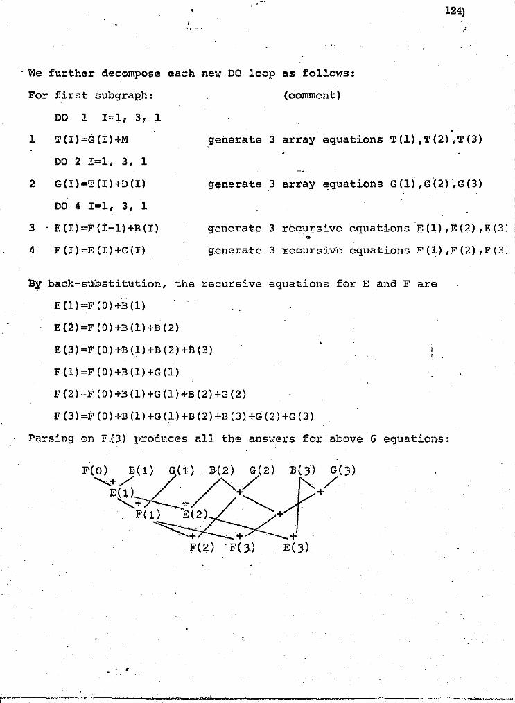
~:
n o o
U IJ _
o [I
II ~ 1
j i
, , ,
" (
~.i;; o' ; .;, ,
, " H.O
. We further decompose each ne\~ DO loop as follows:
For first subgraRh: (comment)
DO 1 1=1, 3, 1 . 1 T(1)=G(1)+M generate 3 array equations T(1),T(2),T(3)
DO 2 I=l, 3, 1
2G(1)=T(I)+D(I)
DO 4 I=l, 3, ·1
3 . E (I) =F (I-1) +B (I)
4 F(I)=E(I)+G(I).
generate.3 array equations G(l) ,G·(2) ,G(3)
generate 3 recursive equationsE(1),E(2),E(3:
generate 3recursiv'e equations F(1),F(2),F(3·
Dy back-substitution, the recursive equations for E and Fare
E (l)=F (O)+B (1)
E(2)=F(O)+B(1)+B(2)
E(3)=F(O)+B(1)+B(2)+B(3)
F(l)=F(O)+B(l)+G(l) ,
F(2)=F(O)+B(1)+G(1)+B(2)+G(2)
F(3)=f(O)+B(1)+G(1)+B(2)+B(3)+G(2)+G(3)
Parsing on F_(3) produces all the ans\~ers for above 6 equations:
F(~+)L(l) G(1)/;. B.(2) :yZ) fB(}) }(3) EO) .. + +
........... + + . F(l) . ~E(2) . ~+ ~+ .. + +
F(2) . F(}) E(})
. ,
~. -"---r-------------'-----'---------------· ~\:'i~,~~·~_,-;;:~;,~,;-t -.:p>,
; , , .1 j .. I .1
1 I 1 I
':1 ':I
"1 l
f···i·······' , .
! .....•..• , .. ' I .. i ; , .
! ",'. 'i ,
. .
1 ;./?

r f i.·.·· I
n ....
o [J
[J
• I 1'1 .' ,
I '
II II [J
.l. ;.0#1<""' ;;:;:1&# h-I¥.? '.-,
" ,"
.. . For the second ioop, 3 array equations and 3 recursive
,125)
-
equations are generated 5 .• , similar ,,,ays for statements 6 and 5,
respectively. We also observe that all three array equations of
56 can be executed simul~aneously and before 55.
VI. Conclusions
Some compilation and scheauling aspects of computation
oriented statements for parallel processing have been discussed.
The treatments have been confined to rather general cases, so
that the results are applicable to most parallel processing
systems. Although other theoretically superior algorithms or
techniques are available, it is felt that their real-time
applications are not so readily justifiable due to the amount of
software/hardware. sophistication, except possibly in some rather
special applications.
j-... --
;~ 1 • -j
~ i J
j , ;~
'"
I

126) , " ."
References
u . 1. C. V. Ramamoorthy and M. J. Gonzalez, "A Survey of Techniques
i:·"
LI
U
i J
i j. I
u
i 1
. ' J i 1 '
~?~~",,-':'. 'l'0 .".
for Recognizing Paral~el Processable Streams in Computer
Programs, "Proc. Fall Joint Computer Conference, 1969.
2. C.V. Ramamoorthy, etal., "Compilation Tecl)niques for
Recognition of Parallel Processable Tasks in Arithmetic
Exprflssiom," IEEE Trans. Comp., Vol. c-22, no. 11, Nov. 1973 • •
3. J.L. Baer> and D.P. Bovet, "CompilaU.on 0f Arithmetic
Expressions for Parallel Computations," Proc. IFIPS, 1968.
4. y. Muraoka, "Parallelism Exposure and Exploitation in
Programs," Ph. D. Dissertation, Univ. Illinois, Urbana, 1971.
5. P. Krasks, "Parallelism Exploitation and Scheduling,"
Ph. D. Dissertation, Univ. Illinois, Urbana, 1972 ..
6. D. Kuck, etal., "On the number of Operations Simultaneously
Executable in Fortran-like Programs and Their Resulting
Speedup," IEEE Trans.Comp., vol. c-21, Dec. 1972.
7. D. Kuclc, etal., "Measurements of Parallelism in Ordinary
Fortran Programs," CO~lPUTER, Jan. 1974.
8. C.V. Ramamoorthy, etal., "Optimal Scheduling Strategies
in a ~lul tiprocessor System," IEEE Trans. Comp., vol. c-21,
no. 2, Feb. 1972.
9. E. Davis, "Concurrent Processing of Conditional .Tump-trees"
COMPCON Digest, 1972 •

II lJ [I ~I
[I
U
D·~ I . , .-.
.D
[]
[J
lJ []
o o o
.. I
" M.
127)
Appendix for II, 3.
I lin ,Experimental Simul tapeous Multiprocessor Organization '"
G. :.>. Mersten o
S. J. Oh
Department of Ele ctri cal Engineering
The City College of The City Uni vel'S i t:lr of New York
Nel'l York, Nel'/ York
October, 1971+
'~This mn:l( ,·ms f3Upr:"J~l.:cd in paJ:"t by NhSA.-Houstt)):l under the Nt.SA Contract NllC9-1.3 9110.
1 ! j
1
I .~

f; ..
I; fl
j1 l!
[J
u lJ
I
! I
• I I . I
• I
1 i
! i I
I ! I
1I
.-:- .•. ~~m"'-~'':'_'''''''''''~-:-~'C'_'?''":-;~l1'"'I-~''7~'''~_'''''_ ,,7~ :;;: .. , v} .,'~..-.:>'~~~J'!"I"" AiW!#il \lA' }"""~I~._-:¥f¥(; .;:i, ------~ •• , .-j
128)
1.0 INTRODUCTION
The purpose of this paper is to present a general overview
of an ongoing research program in the area of highly parallel information processing system organization and the spe.cif1c development and implementation of an advanced experimental computer organizational concept entitled, OI§.imult!2.neous .!:lultiprocesaor Qrganizatio!);OI, abbreviated "SAfilSON OI • TMs work is broad in scope, encompassing:
Q parallelism and parallel processors, * Q cQmpletely independent multiple processors or multiple
~ndependent single instruction single data (SISD) stream processors,
o cOncurrent processors or single instruction multiple data (SDm) stream processors,
o
Q
o o Q
o
o
+ task sharing computational processors or multiple instruction multiple data (MIMD) stream processors, loosely and str.·ongly-connected multiprocessor$ or m.ul tiple instruction single data (!lISD) stream processors. multiprogrammed multiprocessors, real-time multiprocessors, memory organization(s), communications and data routing and, path building and superviso~y control.
It is useful to classify the requirements and problems associated ~l1th a multiprocessor computer system into two classes, as suggested by Saltzer1, intrinsic and technological. Intrinsic
* This paper uses the term "processor" rather than computer here, to distinguish the structure of the computational processing from the overall computer system which includes input/output, r/o, processing; peripherals; etc. .
+ As distinguished from task sharing with separate proceslJors for .1/0, computation, etc.

r ~ n ~:
~: .'-.
[" U ,,;
L 0 ~'.' ,. ".
f u ~. " t
U ~, [' (. u , . ~, i., . • f, iJ f- ,. , , V ,
J f r·'
\ I-" ~. ~.
t.~, ".- I r ,
I ,
" I , ! '
~{' t~ .. ,., Ii
~. "1 .. 1',."
fp
c-
; !
i j , , 1 :
I lJ
o u
129)
requirements and problems are inherent in the problem itself whereas technological requirements and problems are transitory in nature, being inherent to the technology at a given point in time. The important intrinsic problems being studied in this research effort are:
o providing an easy ability to access, transform and share information within a multiprocessor in a controlled manner.
o to provide protection of this information, and o implement an experimental multiprocessor, SAl1S0N. with
these features.
In addition, the technological :limitations which impose bottlenecks within a multiprocessor being investigated as a part of this work are:
o the memory contention problem and, o the communication problem.
In addition, the SAMSON computer, Figure 1, must be a viable system providing a basis for,and a vehicle upon which, research of advanced multiprocessor organizational and architectural concepts can evolve; that is; a research vehicle for multiprocessor computer system development, capable of supporting a ~lide range of investigations in. computer structures and computer science. SAMSON must be capable of possessing the necessary flexibility and computing capability to a'Ssure its applicability to a wide variety of present and future computational applications and to assure the system' s continuing evolution and viability,"
To meet these goals and to satisfy the widely varyin:g nature of the computational requirements imposed on a simultaneous multiprocessor, the system demands a genel'al-purpose computer organization capable of a certain degree of parallelism.
In this research work a strongly-connected multiprocessor capable of SISD, SIMD and MIMD stream processing (which are special
'.~
1 :1
1 ; .• j: ~:
."o,!Ai

~¥£~
;b:,
;';;
~;.,
;..;
:;:r
:,;"
",,~
,~:.
2:~
..a
u w
o_=
,_*'
a
."' "~:
:"7"!"
?"~"'P
I"~":?
:;C:""
~"~'T"
Tl'7'"
~!""""
?~;;>"
":Y'''
'''''
'. ~"t"
;" Ii'
!f F
;"""
', ...
"':"
""'"
~'''''
'''''l
I,e
-1
,-,
!':
J
t I
I .
'---
' -.
-..,
~,
-',
~-.
,...--
.. ...
......
, C
.
' ~
,-,-
, !
, ,..
......
..,
I !
,=; '
I , ..
.. -j
',~"
"l
~-.~--~~~ ~-
-...
-
!.
• M
EMOR
Y
MEM
ORY
DEV
ICES
"
FIG
UR
E 1
SAM
SON
BLO
CK D
IAG
RAM
~g
..,..
;g~
~~
10
~~
~8
fJS;
DED
ICA
TED
IN
PUT/
OU
TPU
T DE
VJ!C
ES
DIR
ECT
MEM
ORY
AC
CES
S D
EVIC
ES
COM
MON
IN
PNT/
OU
TPU
T D
EVIC
ES
~,
... "" S
, ; 1 1 1 j ,! j I
1 W
" v'
I •
~ I.
n=:':i
;::::~
==1~~L
\'i@II
'!hf'i
'N;i\W
W"~",'
;"':==
~"'" ,
~,;
.. i'.::~
~~-::~
: .. ,'=~.
~=~'-·
:-~=~~
~.~~~·
·:."~:
. .c.
' 'j

o [1
U [J
t 1 L,
! I l.I._
I I L! r I L;
\1 I I ; !
i ; I ,
Ii
i I I I
[i
f! [I II .J
131) , 0, _ ..
cases of MISD stream processing) as well as being capable of MISD
stream processing will be developed and an experimental machine implemented, the SAMSON machine. Particular attention will be given to memory organizathm and communications in order to eliminate the classical memory contention and path building problems peculiar to
multiprocessors. Furthermore, the require,ments for multiprogramming and real-time multiprocessing will be investigated and, if practical, one or both of these features, incorporated into the SAMSON architecture.
• 1.1 MOTIVATION FOR PARALLELISM AND MULTIPROCESSING
There are several reasons which exist as motivation for doing research in the area of multiprocessors. Three of the most '
. Ilbvious reasons being improved reliablll..ty. improved maintainability
and ease of expandabili tv. However, these motivations •. in arid of themselves, are not adequate justification for pursuing this research, since duplex systems* (whieh are not here considered as multiprocessors) offer improved reliabili ty and maintainablli ty . while providing an expansion capability through the use of the back-up processor. Thus, addi tional motivation must exist to justify pursuing this research·; this additional motivation is indeed the prime moti vatton for this research.
This additional motivation results from the ever increasing complexity of present day qomputationa1 reqUirements, coupled with
* A duplex system usually consists of two identical processors operating so that, in the event of shut dl.owns due to maintenance, checkout, improvements, etc., of one processor, the second can operate ~Ii thout a reducti on in capabili ty of the system, In addi tion, the back-up processor may be utilized to run lower priority tasks or as a slave to the primary processor (in which case a shut down of either will reduee system capablli ty).
i j
! ' , I
I ' ~ 1 /; 1 : ~~ ~ " ;(

o
lJ
o
11-
II
! I
i I
II
l : II.
., ..... "~-:-,,. ~.; "--""'?~":--'-;"~"'''''~~''''''''''''''''<'';~~;''''''''~''_~h'''''~' -~--,-""''''·''¥J.·'''''''',\''''''i'''''' . ............. "')::= ....... , ...... &4 .... ,'", 4 .. } .. i¢6",S ..... .,.,0IIl. ~ •.
132)
the necessity of ever increasing: data processing rates, response time, and capacity. These .requirements, in specific application have exceeded and, in general, are gradually exceeding the processing capability of some of our present. generation computer facilities. 2
Furthermore. recognition of the fact that generally much of a large computing task is repeated execution (on similar or dissimilar pieces of data) of the same procedure, leads. one to the '. . . observation that utilization of this inherent par'allelism in a simultaneous multiprocessor organization might well provide a dramatic improvement in computing power. 3 0
Consequently, it is the ultimate objective of this research effort to develop a multiprocessor organization capable of a significant increase in computing power through computational parallelism, with increased flexibility. reliablli ty and maintainablli ty, without exceeding the existing limitations of the component technology.
2.0 HISTORICAL BACKGROUND
The concept of parallelism is very broad and includes a wide variety of notions. Intuitively these notions include: many devices working together in some way or other on the same task, devices working together on different but related taskr" and one device performing more than one task at a time. This broad notion of parallelism is, in part, responsible for the ltide d1 versi ty possible within the area of parallel processing, i.e., SISD, SIMD, MISD and MIMD stream processing.
Prior to a discussion of the historical background of parallel processors, the conc7pts of global and local contro14 need be introduced.
Glo1;>al control implies the existence of one or more central contro'. lll11 ts. either centrally .or decentrally located, having
I' . i I
'1 .
,'-'-.··.1 ,'1
I I u ',;
~ , j ,.
.:: ",.--'--' -> ,-[
" .... - , - - "-,
-- ~.-- -- - "

~ 1 I
r , I
I f. ~.
r r " ,.
\' ~. _ 'r .. ~t r; ,';',':
~i ."--, ~ J~
" r
.
I , ~
~~---------------------- P','":" -
)
~ q ::,
n U [J
II U
U
I .-I I I
I U
I I .
i\
, , I ,
I ,
I i I i
U
\, ,. 133)
• .. -"
common control over a ~umber of processing elements. Local control implies control of a processing element by its own control unit (either locally or remotely located).
The SOLO~lON computer5 is a classical machine concept consisting of an array of 32 x 32 processing elements, each con-nected to its four nearest neighbors, under the global control of one j.#
central control unit. These processing elements have limited pro-cessing power; the central control unit processes a single program with each participating processor executing the same instruction stream on its own data stream, SIMD stream processing. Depending upon the internal state and mode of each of these processing elements, they either partiCipate or do not participate during an instructio~ ~xecution. The internal state of the processing element is a function of the data it is processing while the mode of the processing element is determined by the control unit. The principle means of control for each processing element is the mode commands. The major disadvantage of this machine organization and of global control structures in general, is its low efficiency when applied to typical general-purpose computat10nso 6 These computations require sequential execution; consequently, the central control unit utilizes only one (or relatively few) processing elements while all others stand idle •
The ILLIAC IV system7,8 alleviates the problem of the SOLO!10N machine to some degree by: replacing the single global control unit \<11th four such units, by providing I/O access to each processing element, and increasing the power of the processing elements. Each of the four global control units directly governs the operation of an 8 x 8 array of processing units. These global control units may function independently (64 processors per array) or in groups of two, three, or four arrays. all but devoid of local control, mode conditions being the only exceptions.
These processing elements.are status and data dependent
._----------_ .. _---_. __ ..
! -',,; ! ' ...

'. I
. J
1 i LI
, 134) , " ' ..
The HOLLKND machine9 is a distributed control machine consisting of an array of modules, each of which possesses some measure of local control and a limited capability for independent instruction execution. Wi thin this structure the capability exists (to a limited extent) to execute independent programs simultaneou~ly. HOLLAND proposed the organization to provide a basis for theoretical investigations. not as a practical device. Each module ,contains a storage l"egister, operand registers and co'mmunication paths to its four nearest neighbors. Pm instruction stream is stored one instruction per module with indicators to denote the predecessor and successor • moilules (one of the four neighbors). The instructions are executed in time sequence following the above predetermined path. The address of the operand is also stored in the module.' The storage .register can be loaded from an external source during the first machine cycle. During the second cycle the active module determines the operand location and establishes communications betlqeen the operand and the accumulation mOdule. In the final phase the instruction 1s executed. The proposed attribute of local control struct1.l.res is the high degree of hardware utilization that can be achieved when many (small) computations are being executed concurrently; however, the HOI"LAND machine architecture has fallen far short of its goal. The main problem associated with the local control organization of the HOLLAND machine is the spacial struC'ture, of both the array and of the neighborhood communications, ,qhich results in serious path building probl.ems.
In addition to 'the above mentioned array multiprocessors there have been some noteworthy multiple computer systems which have peen developed. These include the PILOT, LAne ,and STAR Systems.
10 The PILOT system ,consists of three independent proces-sors. The basic computer functions are divided, among these three different processors., upon the basis of the processing task. Each processor is optimized to perform one of the fol.lowing basic fl:mctions:
•
.~~.--~~ ··-r
I
1 '
i '-I ,-
I I"' I . I '
'.'

, r ~ j' ~ ,
r- ~ , ~. , • a
U ~'.
[ D ~
~. ,. r n I , ~.
r t-:.
D ~. t ~. n r:-f· --• l'
[l [ t: t";:
i~ ! , L
k , w fl '" • t'i I • ~. '--"".-
~;. ~',j ,
[J ,., ,zo;, ,,~
~l. ~:
[]
~ L!
fJ
. 135)
arithmetic and logical operations, CORtrol aRd housekeeping operations, or input-output operations. The processors are independently programmed to perform their own tasks. The PILOT is not here considered a multiprocessor.
The LARC systemll is a dual computing system cORsisting of two main computers, a totally time shared memory bus (with a maximum of 39 independent memories), and'an input-output processor. The main feature 01:' the LARC system is its memory organization. The memory system consists of a single time multiplexed memory bus and
o
includes such features as overlapping (which makes possible the pro-cessing of several iRstructioRs concurrently). priority determinati on and interlocking memory r~otectioR. The LARC is, here considered, a limited mul tlprocessor; the two main computers are capable of operating ei ther indepeRdently or jOintly to a limited degree.
The STAR computer12 is d replacement system ~tilizing a reduRdaRt machiRe organizati on having one or more (empowered) spares, which are switched on-line to replace units. TO.detect and replace these failures, the.system utilizes: error detecting codes, software diagnostics, software recovery procedures, transient fault identification (by repetition of program segments), and redundant spec~al purpose processors to monitor, vote and replace subsystems. The STAR is not here considered a multiprocessor.
* Other than the ILLIAC IV none of the above are contem-porary processors. The oRly ma,jor contemporary processor under construction is the C.mmp (carnegie Mellon multi_miRi_processor).13,14 Tlue C.mmp is in its early stages and little caD be said in the way
. of operating features. performance, etc. at this time.
* ILLIAC IV is still in the construction and debugging phase; only one of the four quadraRts will be constructed.
G
---- .. ~------------'-"--""-'-r'-'
" ,
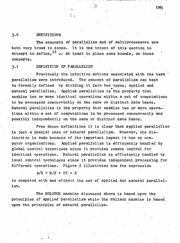
u o n u u , I ! , I L.J
i i L :
i : J
it
! i
i i ! : •. !
136)
, " -..
3.0 DEFINITIONS
The concepts ofparallalism and of multiprocessors are
both very broad in scope. It is the intent. of this section to
attempt to denne,I5 01' at least to place some bounds, on these
concepts.
DEFINITION OF PARALLELISM
Previously the intuitive notions associated with the term
parallelism were introduced. The concept of parallelism can best
be formally defined by dividing it into two types, applied and •
natural parallelism. Applied parallelism is the property that enables two or more identical operations within a set of computations
to be processed concurrently on the same or distinct data bases.
Natural parallelism is the property that enables two or more operations within a set of computations to be prooessed conourrently and
possibly independently on the same or distinct data bases.
From these definitions it is clear l;hat applied parallelism
is just Ii special case of natural parallelism. However, the dis
tincti on is made because of the important impaot it has on oom-
puter organizations. Applied parallelism is effiofently handled by
global oontrol teohniques since it provides common control for identical operations. Natural parallelism is efficiently handled by
\1 I j looal oontrol techniques sinoe it provides independent processing for different operations. Figure 2 illustrates hew the expression
.. 1
~ 'Ii ••••
T I I ' A/X + B/X + CY = Z' Li
is computed with and wi thOllt the use of applied and natural parallel
ism.
The SOLOMON maohin,e discussed above is based upon the
prinoiples of applied parallelism while the Holland machine is based upon the principles of natural parallelism.
--C~--------_____ ..... - ...

r"'~''''-' ;.;.to.'" ~~. ,---,-" •.. -'-.' - •.
f r ~. . ~ r:;'
u u Ll
Fl ! J
I . L:
i
11
U [J
O·
o ., 0
FIGURE 2
(a)
. ~ ..
..
, '7';~;' ':' '-'···~!"_-':-:~~~~~-·7~~~·':'''··'J''T''C'·f,:;.~-.,~-.~ ,j> _:A_ ,:,1. :'_ J .,,,.i - ,$;; £ji::l~: ... ~:t!,-t;'~"!, ., 137)
computation of tht' Expression A/X + B/X + Cy = Z in (a) Hoquenttnl Hteps. (b) utilh:illlt applied parallolisrn, (c) utilizing Ila tural parallelism, and (d) u tilizin~ applied and natul'al parallelism.
.. z
•
I-....;.::;l- Z
z
. ,
•
! ,
I .
i ,;.
• -''!
; ::> '-,:
I I~
! 1 '
APPLIED NATURAL ~ :> r •
.. ---------.----~---~ -..,...--

I . i .
, I I
i ; 1
, , I j
r I U
I; 1 0
~. ;','
0
-'-"~"-?"7'-~~~-~!;l"!""",,,--~ ..... ",,:,,,~,",( . . _ . .,..".,,!~""of."il~"""~~~I""7f~"'."'W;_CP~'."" ~ ........... _il' ......... ",P."";;:""" ._$a,""f.,'*""""'>$", .. ~. f""<;:""'1'"'''''''''''''1''''II.,-,
. -,"j'. 138)
! .. '"
DEFINITION OF MULTIPROCESSOR
Much controversy exists in regard to the definitions 0f multiple computer systems. Frequently, the terms multiple computer, multiple processors, parallel processors, multic0mputerand multipr0cessor are used interchangeably; in this work a distinction is ·made and their broad definitions presented.
MULTIPLE COMPUTERS, MULTIPLE i'ROCES;;;ORS or PARALLEL PROCESSORS as defined in this work are general terms which are used interchangeably and apply to any system contain.ing two or m0re, n0t necessarily identical digital compl:lters. Th~se digital compl:lters may be elementary pr0cessing l:lnits 0r f)lll scale digital c0mputers; they may be conv·entional or U1lc0nventional, general purpose or special purpose, and they may eperate j0intly or independently of one another.
MULTICOMPUTERS as defined here is a group of ,two or more, n0t necessarily identical, digital c0mputers interconnected via their input-output system (i.e. obtaining intercomputer communication by considering other computer( s) as peripheral devices ).. These digital cOl'nputers may be elementary processing l:lni ts or full scale digital computers; they may be conventional or unconventional, and they may be general purpose or special purpose.
MULTIPROCESSORS as defined here is a group of two or more, not necessarily identical, digital computers interconnected on an integrated basis (to effect intercomputer communications) capable of operating concurrently en the same or simila'r phases of a processing task. Simiiarly, these digital computers may be elementary proces.sors or fl:lllscale digital computers, con.ventional or l:lnconventional, and/or general pl:lrpose cw special purpose. (The requirement of operating on simila,r phases of the processing task simultaneol:lsly eliminates the class of multicompl:lters having independent process·ors for ari thmetic functl.ons, control functions, and
r
!
... "

...... cT' . """"----- . - ---- . ----
1_<:,.>m,-e,~~,""·"'~«'·""7"":-"~"'''1'''':''''''·'·~'~'~'~'''::''''''"'":"-~-c::''''''''"'I'' ..... ~,''::\'"'''-'"'''!''' '" ";. ',w '*,:~~""""-;-,-~-P"-"'''''''''": -","'.t. :-,,, "':T' ?',. •. ~ ,-, ~----- - ----.. --~--. - - - --.-.,---~- .".- ". 'J '
u
U II LJ
II u
i I j I
il
't il II ! !
i i 1.,1
! I 1 i L j
139)
I/O functions from being here considered as multiprocessors.)
Bauer's16 definition of a multiprocessor (which he referred
to as a multi-computer system) required that it satisfy the following
four criteria:
"1. There are two or more separate arithmetic control uni ts capable of operating simultaneously and wi th special hardwar'e facility for operating two or more programs siml:ll taneol:lsly. '
2. There are two or more indepently operating primary random access memories.
3. Communications among major elements of the system is of the memory-to-memory type at memory access speeds.
4. All major comporients of the system lire in use during normal operati ons. II '
In this work Bauer's criteria for defining a multiprocessop
are amended as follOl~S: Cri teri on 2, is intended to imply that two
or more ql:lantities can be aeeessed simultaneol:lslYi however, Bauer used this criterion to eliminate from eontention systems having one large random access memory. Systems having one sl:lch large random
access memory, capable of being accessed by more than one processor
simultaneously (i.e. by interleaving), as well as, systems having
multiport memories should not be, and are not here, elimated from
being classified multiprocessors. Therefore, criterion 2 should
read: Two o,r more independent ql:lantities can be aecessed siml:lltaneol:lsly.
Criterion :3 does not apply to systems which provide for
access to a common. memo·ry. Fl:Irthermore, register to register type
comml:lnications sho1:l1d be respected as a possib,le means of intermachine
comml:lnications. In fact, since minimum communication time is frequently a major multiprocessor goal, register to register eommunica
tions 18 an extremely desirable fell.tl:lre and indeed s.hol:lld be a sought
after objective in a ml:ll tiprocessor archi tecture.
! ,,'J
I ' I , ! I, "1
I l.l 1,1 1', i -c.:-
I:
/" ,.,.
I I I,; I'
I} , •. c
~:

i;-
r~:· .. r-t;_ IT.
" , ~~
t:: h :::i:.i .•
"" t:-. .' r ~-;,.:' .
Ii', ", f;' ~~ f '
i-
I; ~-,
[I,
i I l i
,-
I i I i
I I , I i
L I I
Ll
U !l
I I I I I i
. -~', ," --7""""""~-:-"'"~~'-, --,.-.,~."":<"",,,,'7~""---~"-."",,, ""':""T.~,":"~'" ., -'"'"'~_"''I'f''t 0' , :'!!it'?': • .I ;~ItW_ " ii, ' ".,; '. HIP. 99; ' .. let -- •
____ ,_. ___ ."._, ...... __ . __ . ___ ~ :1~' _~~-:'~~~' -:~
, 140)
The frequency of use of all or most of the major components
of the system should be sufficiently high to justify a multiprocessor.
(Unfortunately, I~hether or not criterion 4- is satisfied, assuming a reasonable architecture, is largely a function of the programmer's
ability and ingenuity, his familiarity with the system, and the
nature of the programs for which the system is utilized.) Alternatively, the extent to which a multiprocessor utilizes its hardware efficientl;y
could be 'considered secondary to the speed advantage hoped to be galned by a multiprocessor organization.
o
4.0 SAMSON CONFIGURATION
Throughout the development of such an experimental
multi.processor, evaluations of various design alternatives and a
determination of the effe-cts of .various parameters on total system
performance will be studied. Through this effort we will be advancing
our knowledge of the type of architectural and programming techniques
required of future generation parallel processors to achieve increased
effectiveness, performance and computational capabi11tles.* '
No one machine organization can handle widely divergent
tasks with equal capability. However, the multiprocessor should be capable of handling a broad range of tasks more effiCiently, at
least time wise, than a uniprocesso-r. These tasks should not be so broad that the efficiency of any particular task be seriously
impaired. In the worst ca!l'e a multiprocessor should be no worse
* No specific programming development is intended as a part of this research; however, insight will be gained regarding programming techniques during arch! tectural development.
--------------------
J
l ,

"
-=l~~--:·
n
~ _ " .. ~ ~"". __ ..." ""..,....'"V""".''''''"'''f~~-~-~. ~ ........,,-~"'~..,...,..'""""".,......,.,.....-_""""""'~.~_~~_.""M -,"".~"!I",,'['I':"'" "'" -.":'*'" ?"'_#_="' __ '_""Ht"_':'"I~' -..
G
fJ
o []
II
i I I , Li
[ I , I
I
I 1
I ! I'
r·' Ll
.. -.- --'"-"-~'------'-.---' .
, . 141)
than a general purpose uniprocessor.
Haraware utilization efficiency must be secondary to
computing power if system versatility is sought. If the tasks to
be handled are highly restricted and well defined. in advance, then
special purpose hardware can be utilized to optimize the processing tasks. However, use of such S,pecial ptlrpose machines, on tasks not
originally included' in the limited set of tas!<s considered, lq~uld be highly restrictive and inefficient.
Consequently, if versatill ty is a goal, a general-purpose
architecttlre is called for and the related-inefficiencies associated
wi th particular tasks must be accepted. A general purpose archi
tecture tends to increase total execution time; this 1s equally true of uniprocessors and multiprocesso,rs.
4.1 OPERATIONAL FEATURES.
The operational feattlres of the SAMSON machine must
include the facility for data manipulation and computation as well
as the capability of controlling the sequencing of instructions.
SAMSON will include all of the conventional facilities
for (local) instruction execution and it will provide global
instruction features. In addition, SANSON will possess a high
degree of concurrency in that simultaneous operation of several
processors jOintly on one task or separately on different tasks
will be possible.
The basic processor (central processor) elements of the
SAMSON computer are 16 bit general purpose mi·croprogrammed processo'rs
having multiple general ptlrpose registers operating on 16 bit data
words. Their instruction repertoire will include special multiprocessor instructions (global instructions), such as FORI(, JOIN. etc.

[' r D . 0
~,
,
o U
LI
I , , I
I '
, i
. I , ,
I : i I I I I ' 1..!
[j
[j
[I
U
The major characteristics of the SAMSON processor elements are:
o Type --general purpo,'Se, digital, binary --full paralJ'el organization --m1croprogrammable
° Arithmetic
--binary, fixed point --16 bit data word --negati ve numbers in 2' s complement form *
142)
~-add time: 1 ~ sec (register.to register) 2 " sec (memory to register)
--multiply time: 21 /-L sec (Average, register to register) --divide time: 27.5 U sec (Average, register to register)
*
o Memory.
--DRO core --1 I'· sec cycle time --each memory is expandable to 32K words in 4K or 8K
increments
o Addressing 11odel?
.. -direct addressing to 512 words of memory --indexed addressing (execution time anaffected) --multilevel indirect addressing
o Input/Output
--program interrupts expandable --power fail and power-restore interrupts can be
provided --I/O communicates with CPU and memory by means of
separate common data and address bus; I/O devices . cal'l be added as required
--stal'ldard peripherals - teletype and/or CRT display and paper tape reader '
Execution time based on a memory cycle time of 1 " sec.
j
:1

j ,
; I , ! lj
[I
[L i I l--:
i \ I,
[I r ! l J
4.2
~ , "
" '.-
o Logic
--implemented with LSI and MSI arrays of T2L
MEMORY ORGANIZATION
1.43)
Multimemory ac'cessability is required at the processor
level in a multiprocessor since, in general, it is impossible to
operate solely out of one memo'ry unless swapping procedures, anti
cipative procedures, or mapping techniques are utilized. Although
these features are desirable in a uniprocessor memory hierarchy to obtain an economical configuration, their usefulness as the primary
~
memory for a mul tiproces'sor is questionable. Nevertheless, these
techniques could be utilized to supplemant the primary memory.
SAMSON' S present memory organization will not include these features; however, provisions can be provided for their addition at a later
date,' should the research in this area so indicate.
A modular memory organization consisting of several small singlepor,t memories, rather than one large common multiaccess
0r multiport memory, w3.11 be utilized in the present SAMSON
archi tecture. It should be noted that this was one of Bauer's
criteria for a multiprocessor and although exception was taken pre
viously, the exception was based upon this crlteria being a necessary
condi ti on (and not on it being a desirable condi ti0n). Each memorJ' module will be acnessible by all processing elements. This scheme
provides for parallel transfer of individual words or entire memory
modules using present day switching technology; thus pr'oviding the capability of transferring large quantities of inf0rmation at full
[i memory rates. This mul ti-memery organization allows prcl!:rams and I \ I
LJdata to be shared by several processing elements en a high speed
[j
[]
basis while providing a means of insuring privacy of data. \fuen
independently operating, the precessors which comprise the SAMSON
computer system will be able to communicate via memory to memory transfers under program control. Memory transfers will be on a

'l .. t:f;.-:-~','::'!::-'!L~~~===~, ___ . __ ,. __ . ~~"~"~'~-"""""~~_~~ ___ ""'.,~_:_"' •. ~.-'_Q",,,_-_.~--.. :._ .. -=--,,,,,._,,,._,",,,._-,,,_.,,,-¥::,_,,,,,_ . .... _, .... rw ... , ... , -,,"'_. __ "':~ .. ~._~"z*"'*""'~.ll!I'f"'j"":;"'_~'i":,'_~"~"'''!I, __ ,
n .....
u rl U r']
U ~I I i,_
[ I LJ
i' U
~ f 1 ' , 1 ... -
n u
144)
request basis, thus avoiding catastrophic memory destruction. Careful consideration must be given with regard to providing a means of insuring pri vacy and protection of data without unduly lim! ting the capability of sharing.
It is intended that at any given time each processor can have access to several memories, but only those assigned to it. Furthermore. any processor (if assigned) can have accessibility to
, ,
all memory modules (memory stacking) which would be in excess of its inherent addressing capability; thus providing an expanded high speed memory capacity. -
In a multiprocessor, it may well be desirable to be able to write identical, duplicate copies or data and/o~ instructions into several memories without any additional expenditure of time. This feature is presently being considered for the SAMSON machine. Research in this area is required.
The above memory organization enables the total computing power of SAMSON to be applied to those tasks requiring the full computing power of the machine.
4.3 COMMUNICATIONS STRUCTURE
The communication reqUirements of a multiprocessor can be divided il'lto two classes of communications: intermachine communications and input/output (I/O) communications. In either evel'lt the time 'investment made in establishing the connection should be minimal, or,alternative~y the connection should be retained for a relatively long period of time in order to justify the time expenditure in establishing the communication link. the data rate should be suffiCiently high to satisfy operating requi remen ts.
Furthermore, system
Three basiC communications techniques exist where by the major system components and peripheral.S can be interconnected, namely,

f' r I
I U u U I ' ,I : I II
, I
,I
i '
o
145)
space-division, time-division and frequency division.
The space-division techniques. includ1ng completely dedicated commun1cations as well as multilevel switching techniq\\es (crossbar switching). are conceptually the Simplest. However, an excessive amount of hardware is required and/or operational difficulties such as path building •. conflicting. communications reqUirements, and extended periods of time required to estaol1sh connections may occur.
Time-division or t1me multiplexing techniques are a •
viable alternative approach. Here qu~uing and priority schemes are utilized to insure that one and only one device pair can have access to the data bus during anyone time slot. With this technique time slots. can be either preass1gned or a dynamic allocation procedure utilized. The drawback of this techn1que 1s the possibility of one device pair (with proper priority) cbmpletely tying up the communication link.
A frequency-division (frequency-multiplexing) scheme appears to offer the greatest flexibility and potential. The major drawbacks to this approach are: carrier frequencies in the range of 100's of megahertz are required (to meet the processors data rate1? requirements) limd furthermore, the necessary h,ardware for modulators and demodulators (which are not standard computer components) needed for transmitting large amounts of information would be excessive.
INTERMACHINE COMMUNICATIONS
SAMSON'S intermachine communications, as presently viewed, will be a cembination of beth time multiplexing and spacial communicatien techniques. It 1s felt that this approach is the most amenable to present state of the art computer techniques.
•
_1_"" '-'---" : .' "-_:,

\}
~"" f
•
~ t.~~ __ ~
_'.l-I ____ _
til tlJ
JI
l I
. " " .
\:
, ' ,
'JI t 1
'II ~L 'II
II
'I ! " I :\: i rI
[I
Memory communications wlll use both of these techniques, in that each memory will be a'ssigned a' dedicated' communication path to its associated processor as well as a connection to the common intermachine memory communication,network.
Intermachlne reglster to register communications is also being considered for SAI1S0N. However, no decislon has been made whether such communicatlons will be lncluded in' the pres,ent SAMSON archi tecture •
4.3.2 INPUT/OU'l'PUT FACILITIES
146)
The purpose of an input-output (I/O) system is to efficiently, reliably, and in 'an orderly fashlon transr'er the maximum amount of information ln a minimal amount of tlme and with minimal lnterference to oth'er sUbsystems. The I/O philosophy should provide a general purpose interface with all the necessary control and communlcatlons paths to allow data transfers between the varlous perlpheral devlces and the maln processing system.
I/O communicatlon requirements differ from intermachlne communication requirements since the peripheral devices have'widely varylng characteristics, because of the multlpllcity of the peripheral devices, and the unrestricted physical length over which the communication may take place. An additional fundamental difference in the type of communications results from the asslgnment of peripherals. Whereas memories are assigned to computers control (either by request or otherwise) I/O perlpherals
under program belong to a
common pool of devices whlch, although available to all, are only "loaned" to a particular processor. to the assigned processor until the
The peripheral remains on 10an request is fulfilled or in some
instances until an interrupt o,ccurs fr0m, a higher pri0ri ty source.
'Reasoning as above, SAMSON's I/O communication philosophy will be based upon a time multiplexed system. (Fixed time slots will

!J
U
f I LJ I 1 ,. !
Ii
i , I
i ' I I , I
I : , ' J L 1
i I 1 ' LI
· . . ,
not be utilized here due to the pseudo random nature of the required interconnections). Furthermore, the I/O system will be a requestresponse system, thus allowing maximum transmission rates over various physically d1fferent length paths.
In addit10n, the SAMSON I/O facility includes both internally and externally controlled data transfers.
. 5.0 RESEARCH 3TATUS
It is the objective of this work to physically implement the SAMSON machine, as described herein, with appropriate modifications reflecting the results of the ensuing research.
The SAl-iSON machine will be a useful tool for performing precise mathematical operations across a broad spectrum of applications while providing a mult1.processor both suitable'for, and with the necessary cap~,bilities to enable research in such areas as:
o Multiprocess or archi tecture (fe\~ mul tiprocessors have been constructed; thus each represents a major research milestone)18
o The processor-memory interconnection o The memory contention problems. o The communication and control of a multiprocessor
memory o The communication structure of multiprocessors o The instruction repertoire mandated by a multiprocessor o Applied and natural paralle11sm o Global and local control o The hardware operating system o The effect of a multiple accumulator and/or multipie
index register structure
,
! 1 I

r' ',~_~L~~,=,. ___ . ",~~' f-
~-
I'
n ..
H
U
U
! I L,J
U i I
~ 11 <
0
0
0
0
0
0 0
It
Interrupt handling, DMA operatt".l, cycle stealing and pr10r1ty ass1gnments The effect of a h1erarchical memory organ1zat10n on a mult1processor The effects of overlapping, prefetch1ng instructions and operands, multiple instruct10n decoding and condit10nal branchine Data flow efficiency and 1nput/output flex1bility Diagnostic procedures, reconfigurat1on and degraded o};:eration The optimum sequencing problem Software application versatility, decomposition of computations and overall executive efficiency
is beyond the scope of anyone research effort to study all or even most of the above mentioned subject matter. Some of these topics will, be covered as part of this research 1n the development of the SAMSON mach1ne; ioeo,' mult1processor arch1-tecture, processor-memory interconnect1on, memory-content10n, memory communication and control, communications, instruct10n repertoire, parallelism, and global and local control. It 1s felt that the subjects covered' by this work, the addit10nal subject matters listed above, as well as any add1tional top1cs uncovered as a result of th1s and other research efforts will be continued
148)
in future research activity. It is felt that SAMSOI, will be an invaluable aid to future research efforts in the area of multiprocessors since research in this area has a strong experimental and ,empirical compone~t requ1ring research, design and construction of many systemso 19 '
The SAMSON machine is in the initial research stage of development and w111 conSist of fo.ur (4) uniprocessors capable of concurrent process1ng (as a st'rongly-connected multiprocessor).
,
1
1
I !
I ,
. -.~

~';':,
~ I ,
l I ,;-" I S," I" '," i!." W:" I ! ,.:-f.;,
L ,
I ~;, I , I
i , ! ~ t L }": . . h t: 1'1 , [I
i i
I 1.1
i I ! I
I I 1 !
1I I' n ~
D -
/,
11 r"
, Ii( t~·""-~~ ;-k~~.-'._ -
149) , ~ .. ~
The first SAMSON processor element is presently oeing deougged. Similarly, the SAMSON test set 1s also in the debugging stage. One piece of support test equipment has been completed and is being used to assist debugging of the SAMSON processor element.
,
T~' !
;1" '--'
:i
.1
:~

'".
o o !J [j
~j
iI ,
I , ..
~ I
i , i i l.1
I I 'u
[]
LI
o U
n ij n ~ 2,
, ~7
1,
2.
3.
4.
5.
6.
8.
10,
11,
12,
13,
14,
15, 16,
17,. 18,
19,
, 150)
References
Saltzer, J, H,; Traffic Control in a l1ultiplexed Computer System, MAC-TR-30, TheSis, MIT, Cambridge, Mass" July 1966,
Curtin, \~, A,; l1ultiple Computer Systems Advances in Computers, 1963, 4, 245-303,
As chenbremler , E, A.; Illtrinsic Multiprocessing, Spring Joint Computer Conf" 1967, 81-86. ,
Koczela, L, J.; The Distributed Processor Organization, Advances in Computers, 1968, 9, 286-353.
Slotnick, D. L.; The SOLOMO!, Oomputer, Fall Joint Computer Conference, 1962, 97-107.
Murtha, J. C.; Highly Parallel Illformation Processing Systems,Advances in Computers, 1966, 7. 1-226.
Burroughs Corp.; ILLIAC IV Systems Characteristics and Programming Manual, NASA CR-2159, 1973, Feb.
Boulmight, Iv. J.; The ILLll\C IV System, Proceedings of the IEEE, Vol. 60, i,. April 1972, 369-388.
Comfort, W. T.; A Modified HOLLAND 11achine, Fall Joint Computer Conference, 1963, 481-488.
Leiner, A, L.; PILOT - A New Multiple Computer System, Journal, ACM, 6, 1959, 315-35.
Eckert, J. P.; Design of UNIV':"C - LARC System I., Proc. of the Eastern Joint Computer Conference, 1959, Dec. 1959.
Avlzienis, A.; et a1., The STAB Computer, Jet Propulsion Laboratory, Califorllia Institute of Techllolo,gy. '
Bell, G, C, and \vulf', H. A.; C.mmp - A 11ulti-mini-pr0cessor, Fall Joint Computer COllference, 1972" 765-777.
Bell, G. C. and Freeman, P.; C.al - A Computer ArChitecture for AI Research, Fall Joint Computer Conference, 1972, 779-790, Koczela; op. cit., Distributed Processor; 289.
Bauer, W. F.; \fuy 1~\:Ilticomputers? Datamation 6,
Curtill; op. c1 t., 11ulttple Comput,er; 256.
Belli op. cit., C.mmp; 766.
Ibid., 765.
Sept. 1962, 51-55.
I:,

,.., , k ?'
; ,
f, ( ! f. ~".
i<.,~,
L r f ~.
t-" , ~'~ [ ~ .. f" t' , " ; ~. t"'-
t I }'.'
( ;,' '",.-
" ,
" ~ .. ~F'
• ~)'
~
f' ·1;,
" ~~ '-~~ i,'';'-.
-
;1
1 'j
~.
'\i i . ~ ••
f] ,I { .
0 fJ
~] ; I U
[,
, i
-- I
;1 U
" lJ ~ ] j ~
III.
"-"":""'"'-'""""'1 151) 11
" II
Digital Cpmpl!f:er Si,.mulaf:i()n and Aut()Il'latic Fault DetecUcm £9r Spac;§
Shuttle Electric Power Distribut.i.on System
by F. E. Thau and C. B. Park
One aspect of our analysis of the Space Shuttle power distribution
system has been concerned with the development of a flexible digital
computer program, comprisi,ng a fixed main routine and a number of
user-supplied subroutin,es, which simulates the dynamic performance'
of the distribution system. given a specification of a sequenc'e of .mission
modes and the load distribution in each of these modes. The programl
previously delivered to NASA, has been tested successfully on a network
of about the size of one third of the proposed power distribution system.
This program. can be applied for the evaluation of competing proposed
modifications in the electric distribution system, structure or in the ratings
of ele,n,ents of the distribution system. A description of the program is
contained in section III. I •
A second aspect of our analysis has been the development of tech~
niques for automatic fault d.etection for application in future :;;,pace shuttle
designs. Two approaches have been taken: a reduced, search procedure
was developed to use a limited number of physical m.easurements together
with a listing of nmninal conditions to automatically specify which loads or
cables are faulted. This approach is outlined in section III. 2. a. The second
approach uses a dynamic model of the distribution system in the design of a
sampled - data observer or filter whose inputs are the available measurements
of voltage and current and whose outputs are the state of the power distribution
system. This approach is outlined i'n section lIT. 2. b.
,
11 I'j l
I •
IJ
···.1······
,
"
'. ,','
i ''';'

!' ..•. ~ ... c:
I.···.·.· .. •.·· ' "
;;'
~ ... ! c:.~ f: r L r t. , ii'-~. ~' r
~,:
,
, f, '~" . !'
; ~"
1.-,,:--
·."4
~ ~~? ,
~ 'j , [i It!
~
iI .. ~ ••
o o o o Oi , I] L.
o u
[i
~]
~p. il,! .. ,.
n '''''
152)
i,
A number of problems remain to be studied in order to apply automatic
fault detection for future space shuttle power distribution systems. First,
the automatic fault detection schemes outlined above should be tested
on networks of full size to determine the computational requirements
that each technique would impose on the on~board com.puters. Second,
automatic fault correction or reconfiguration techniques should be developed
to fully implement an automatic fault detection and correction sub-system.
~-----
; !.
I

Ill. 1 - SIMULATION PHOGHAM DESCHIPTION FOR
SPACE-SHUTTLE ELECTRIC POWER DISTHIBUTION.§YSTEM
SEPDIS PROGRAM
153)
. A configuration of the electric power distribution system of the space shuttle
is assumed. A sequence of distribution modes of the power system associated with
relay states is also given in real time. The operation of the power system follows
the schedule specified by the mode sequence. Section I gives the analytic basis for
the simulation program. Section II describes the program in detail and Section m . contains an application example.
A. Simulation Program Background
Assumptions
Assume that the electric power distribution of the shuttle spaceship (EPDS)
isrepl.'esented by a schematic diagram in Fig. 1.
foweR
SysTgM

.----_~~~__._;o' :.c.:..-c .:,' C .~;:~:..:.-",. '='"==============:-""'-"'''-'''. =~''',*:!!?",~,,"'.;..' "". ".",. =t.!!!,!!~=!!!!!,!!~:;."'Z1'!!t'l!I¥!!!.'!3!""P::#!"!.,~,,,!3~1:!!!l!!I'_. __ :
i ,
J
I j
I . I
r:; :- I J
, ,
..
i ,
J i
<; iJ (
I; [ I ~. I
~r
'. , I ~;-. ! ;'
l~
! l r ]
~ ;::: L , f;'"
~ -") ~'--"
..
1 4 i' 5 ) ~
In Fig. 1 the non-linear function of I, f(I) depends on the nature of the V-I character
istics of the given Fuel Cell (D.C. source). Assume that all the elernents of the
power system can be approximated as linear, lumped, and are given as .circuit
elements for a given mode, i.e. ,
1) Dynamic of each load is described by a linear differential eq,or by a circuit
description
2) For simplicity each relay is simulated by a Resistor R
R = 0.01 0 when closed
R = 108 0 when open
with a delay time given.
it) Determination of System Dillferential Equation
One can describe the dynamic of the given power system under the' assumptions made by
[-~-H~ i ~l [-~-H~-J u ... Es., A21 J A22
(1)
!!. = [t] [ f ~)l [~ J V- f(I2) 1 = J
f (Ia)
C P 1 =
• 9
Where
input variables
g= state variables of the system
•
:' .. '
;;
, I ,
,
• j
I

:;;:--
II o o [1
! I ! I.
! ( f •
,U
r I u
r 1 L1
• z= • ~
• • •
output variables of the system
auxiliary variable's which connect some states, input and output variables
155)
A determination of the submatrices Au' A12 , A21 , A22 , E, GI , G2'depends on haw to choose
the auxiliary variables and state variables as physical elements.
From the standpoint of camputer analysis af the ca'mplex circuit Ref. 1 the state
variables are taken ta be all the inductive, currents ,and all the capacitive valtages.
Mareover, let the auxiliary variables be all the node voltages and all the branch currents
eJtcept for thase nade valtages and branch currents carresponding ta state variables, i.e.,
YN z=
rb -.
Where V -N =
VN1
V ' NNNade
.!b =
Vi indicat.es the i-th node valtage (i = 1.2, ••• , NNode)
Thi
indicates the i-th branch cu·rrent (i = 1,2, ••• , Thr)
Rewriting (1) in terms of physical variables .YN
, lb.!l gives
o .YN Bl
o = .!b '!" ~ -,- -F3!! 0 I A22 q 0
Thl
• ' . •
rb 'Thr
.!I
•
I

,T. ;,
o U D
o [I
l \ U iJ
i I , ' I I
I i I
r I I I LI
u
156)
(2).
Where the submatrices Fa. F12 • FiS • Bt are determined by applying KCL law at each
node. Therefore. the NNode x NNode matrix Fu. NNode x3 matrix B1 are null and all the
elements of the matrices F12 • FI3 are 1 if entering into the node, -1 if flowing out of the
node, otherwise zero. And the submatrices F 21 • F 22 • F SI ' A:!2' B2• and E are deter
mined so that all the branch elements. resistors. inductances. capacitances and inde
pendent sources are defined.
iii) Formulation of Normal Form of State Equation
To formulate the normal form of the state equation from the system differential equa
tions l2), one has to eliminate the auxiliary variables in eq (2'). For the elimination of
the auxiliary variables a gauss-elimination methad has been used. i.e., fram (2) ane
Where the indicated inversian of the matrix is assumed to exist.
Fram (2), (3) one can obtain state equatian
Eq = - (FSI I 0) ~_ :~1?. =) '[f !'Ja.) P!'211F22 l 0
q+ r~'11· Therefare, the normal form of state equatian is 1
~ ~ I o -I I 0 I F12 F IS -I q =E 22 - [F~I' o} [--- I ---J [---- q+E" - I F 21 :F22 0 -
[£-! foUl [-<2-1]!! . F21 , F22 B2
(4)
.,
, j
!1 :. '.~ .. ;.'
. . : :.;
: "
: ..,' ,

,
n ," ...
n [J
o II L
11
1I
i I j I
i] L
u
u t ~~.; .. n 1.. • t:
and
t~l 157)
I = Csq - - !!.
iv) Solution of Non-Linear Differential Equation
The dynamic of the EPDS can be described by a set of non-linear differential eqs,
• q = Aq . + B!!
[~ 1 [ ""1 .!L = f ~) (5) f(I3)
where all the elements of A, B are given.
A solution of the above non-linear differential equation becomes very much unrealistic
when· some of eigenvalues of A are very large. When some relays are open that may give . 8
this case since the relay is simulated by a resistor whose value is 0.01 if closed, 100
if it is open. To integrate the system with some eigenvalues iarge, one has to take a very
small integration step size which may take prohibitive large integration time. One may
overcome such a difficulty by finding steady s.tate solution of some state variables corres
ponding to very large eigenvalues as a problem of singular perturbation.
B Computer Program of Simulation of EP1)S
Computer program of simulation of EPDS consists of four main steps, i.e.,
(1) Read data according to the specification of a circuit's branches and their con-
nection a'1d formulate a set of system differential equations. Read data for
mode sequ,ance associated relay states.
(2) Reduce the system differential equations to the state Ilc;>rmal form.
(3) Solve non-Hnear differential eg.
(4) Check all the relay states according to a mode sequence and modify system
differential equation.
To see these steps refer to flow chart.
~ :.~ AA·~_- '- --y-------

k ::..;--
e.-r'
~:
~ . . , :-.-,
'" ?, ;roc
tft, ,
~i !' , It j,:"
I , , !
d LJ
[J
[ 1
I
I I
I
Ii ' i !
I,
FLOW CHART
\<EAD DATA I SIO~ THEM a.-tld CALL QAT' "I TO READ CIRCUIT
$PE.Ct Ie 0
CAL.L PL.! tJS to st"at.e. _
GALL
STOp
•
:::)4)$: 4Jiy
158)
No .
i -, 1 ,. ,
I j ,
--'--'"------,-- '-, -"'-._--,-----.,,- .. -- - - -- -. ---'--------""'1, .. - .. _~"i_·'.

, ,
I $."""",""r.;;.I'"'~'_
n L
II
i ' I ' ~ I
'"I
II , , I , ,
I , ! : i l ! I
r I 1
I".," 11
,,1 II I 1 r ~: ~d I, (' _,
.' Ii II t. j . , r
~~: I, J ri~~ I
~~ ~'.----
. , . fA·'" ii..uS • twa. k 6 '"[FOG' . ~
As shown in the accompanying flow chart, the SEPDIS program consists of six major
subroutines, DATIN, RELAY, PLlNS, FUEL, AJ.OUT, RINPG.
SUBroutine DATIN (I(ECT. VALUI,. NR, NL, NC,NV, NI. M.NCV. NCI.NEQN,
NVAR, NOU, NN. NZ, NAUX., NK, 1(11, NO)
159)
DA TIN reads all the circuit ek:ments. resistors, inductors, voltage sources associated
with two nodes and store them in KECT and in VALUI (corresponding numerical value of
element). i.e.,
Outputs: KECT, VALUI NR: number of resistive elements NL: NC: NV: NI:
M: NCV: NCr: NAUX: NVAR: NEQN: . NOU: NINP:
II "
.. II
It U
.. II
II " .. " " .. " " " " " " " " " "
NN, HZ, NK, K11,
inductive " capacitive " independent voltage sources independent current source:;; mutual inductances capacitance voltages capacitance currents auxiliary variables the or.cter of system NAUX +NVAR number of outputs number of inputs
NO are working variables
SUBroutine Relay (NRLAYi R. illY. NR, T. TSEQ. NMODE. IJK. KECT. VALUI, VNl
Inputs: NRLA Y. R, illY, NR. T, TSEQ, NMODE (READ), IJK (Main). VN (see note)
Outputs: KECT. VALUI
~
Note that a diode can be modeled by a relay associated with two adjacent mlde voltages.
However, in this subroutine simulation of diode has been neglected at the present program.
SUBroutine PLINS (A. B. KECT. VALUI. NR. NL. NC, NV. NI. M. NCI. F21, NK. K11.
NCV. NEQN. NINp. NVAR. NOV. NN. NSVR, NO. NZ. NAU:X,.GI, ~RPT)
Inputs: KECT (DATIN). VALUI (DATIN). NR, NL, NC, NV. NI. M. NCr, NK. KIl. NCV, NEQN. NINP. NVAR. NOV, NN, NO, NZ. NAUX, (all from DATIN) , NPRIN (READ)
Outputs: A, B, F21, Gl, NSVR
A: System matrix F21 Input "
(see eg.S) ,
, ; .~

IF ! ~
! , , ,
f r It -r-~. , L !
r , , t. ~;
r L
t· , -
'.'
I'· g I
f]
[J
[1
rl LJ
[I !....J
) i J
[I 1
i .J
I i j , ;'-1 , ,
I
I ,
I i i I
r I L __
[j
NSVR: number of state variables
SUBroutine Fuel (YIN. X. NOes. !'IVAR)
Input: X (from read initially and from integration subroutine RINPC) NDeg (read), NVAR (DATIN)
O~:t~[:::1 _ [:(~;:l. (see fig. 1)
32 £(la)
where the non-linearality must be programmed in the subroutine fuel.
160)
SUBroutine ALout. (F21, YIN, X, PN. VN, NSV, ITK. T, Numbr , NDeg, NLoad, NNode,
NAUX. BRC. W. GI, NINP)
Input: F21 (pLINS), YIN (Fuel), X (RINPC), NSV (NSVR), IJK, 'l'. Numbr (Main),NDeg, NLoad, NNode, NAUX (I.ead), G1 (PLINS), NINP (DATIN)
Output: VN, PN
VN (0 ): all the node voltages, branch currents
PN (oJ.: instantaneous powers at all the loads. At the present time, PN (0) has not been programmed
SUBroutine RINPC (X, DX, T, step, ISW, Rmax, Emax, NDeg, NLoad, IJK, YIN, A. B,
NSV, Numbr)'
Subroutine RINPC is followed by subroutine DERIV (DX, X, YIN, A, B. NDeg, NSV);
In the Subroutine Deri v Input-Output specification is as follo'ws:
Input: X (RINPC and initially read). YIN (Fuel), A, B (PLINS), NDeg (Read), NSV (=NVAR)
Output: DX describing the given dynamic structure of the system, Le ••
DX=AX+BU
The arguments of the subroutine RINPC is as follows:
Input: DX (Deriv). Step (Read). Rmax (=TSEQ (NNode) , NDeg (Read), NLoad (Read), YIN (Fuel). A, B (PLINS), ISW .. IJK, Numbr (working variables)
Output: X
An integration routine in RINPC is based on the fourth order R-K method.
RestricUo.ns on the Present Program
1.' The dynamic system is assumed to be at rest inl tj ... lIy .
2. Only circuits having 60 system variables (= number of auxiliary variables + number
of state variables). 10 state variables. 3 inputs. are allowed.

, I ..
I. ~.
r" ·1 ~=~--j..".,.--~-..
, ,-.'"'" , -.... '.~"'"-.-.-~'.-~<~'~-_."c,-'.:~ ..... ~._,r-... ~_, ~~·~~~'?~ __ .~I "",,".~'~'~ .. ~' __ 4 __ ;~ .. ""_4~_':"' __ ". "'" •• "."'-t .... &~ ...... , .. m ....... ',·_ ... *-.. A,_ ........ ">;-'=!!ri:(:5'i} .-* '. O'f --'1
I 1 . I i
I
[ : ! I
I !
1 i
161) Input to Program
. The .,resent program aocepts oircuits having up to 60 system variables (= number
of state variables + number of aUxiliary variables), 10 state variables, 3 inputs, no
restrictions on output variables.
(1) DIJ-ta-input to the Program
Bloc.k 1
i) The first card provides the number of relays, the number of modes, the number of
loads, the number of nodes and should be punohed in the format
13, 13, 13, 13
ii) The seoond card gives an initial integration step, initial time, and frequenoy of print
out in the' following format
E15.5, E15'.5, I5
Block.2
i) The first set of cards in Block 2 provides the mode sequence in real time and is punohed
in the format 4E15.5
ii) The seoond set of cards gives the locations of relays in terms of node label, i.e.,
my (I, J), J=l, 2 will identify the I-th relay by two nodes. The format is .
. 213
iii) The third set of data oards in Block 2 provides all the relay states, i.e., R(I,J)
indicates the i-th relay state betw~en the j-·th mode and the (j+l)th mode. The tbird set
of data cards should be punched in the format
4E15.5
Block 3
Block 3 defines all the branches of the circuit to be analyzed. For each branch a single
card should be punched EL (I, J) = :.A
in the format lAl, lX, 13, lX, 13, 2X, E16.5
The .integel' i and j are the initial and terminal node labels of the branoh, respectively,
and EL defines the kind of branch
EL=R if branch element is resistor EL=C ." II n II capacitor EL=L "" "" inductor EL=V "" "" 'voltage source EL=I"" "" current source

, L,
,". f-
u o u u u ii
. I
. I
162)
The number A, the numerical value of the branch element EL, the number A may be
any real number if EL=V. The last four cards in Block 3 should punch in the first
column for each card.
_ C; Example 1. EX;l.mple of ~nput Data Format
Consider a following two loads problem with one input as a test problem.
" 4-;/..2...fl \..fL
52. V b 0-
IH ( 0 -
i j Assume that the syst<Jm is rest initially. Analyze the transient response of the system . I"
, , : I ! J
II I ' .1
II ,I
Ll
II I'" I I' t,
from 0 to 1 second when the relay between the node 1 and 2 is open at time 0.5 sec.
f(I)" Exp. (-.0.01,*,1 )
Input Data
Blocl~ 1
i) The first card 3 3 2 6 (~n the farmat 413)
it) The secand card 0.01 O. 10 (in the farmat 2E15.5,15)
Block 2
i) The first card O. 0 .5 1.
ii) The secand card 1 2
The third card Z 3
iii) The fourth card 1 1 _
(4E15.5)
(213)
(213)
(4E15.5)
The fifth card 1 1 1 .(4E15. 5) The sixth card 1 0 0 (4E15.5)
.j ·1
1 1 I , I I 1
1
J
; .: ,
i·', I' I ' ! 1 :-:
.'-'

n D
0
:~' D
D r .J n H
f:- ,
1 H 'i
f ;] ~. R •• ,
Block 3 ,
R 1 2 1. E -2
R 2. 3 1. E-2 :R fl. 4 I, E-Z R 352.2.EO
R 4- 6 1. EO
L f 0 1. EO
L 5 0 1. EO
<~-7'~'~~'~~?~:-'~ ._~"_ :'-7~~: ':"-~~"'~ "","_ x. Ii ;;: mhj. ·~¥~t2, -"# _>-? :?'?~lfVi-;»':;-i~,¥iJ-" V .
163)

.,. "
I' ~ "
~.
,-'~
" ~~-:--
~, '
L~,;
~ ~ r~'i:ti
o II U
o
i I :.1
, I : I"
t i
ri I .
. U,
1 [ , i
j I
"j , , U 1
~'
,i ,1
0 , 1
1 " " j
U j , 'i
.. :l
n, I j L
.I
"I Ii 1 , -,
f'i ~~. ;!'\
j
,"'" !>;'!II
Example. 1 PRINT - OUT
state Equations for Each Mode
---STATE EQUIH ION PR INT-OUT *****~******************
164)
- STATE--EQUATION PRINT-OU ... I---
* ***. *. **.*************** ----------- ------_._._-------------'---------_. __ ._-- ---- -------
I NOUCTUVE BRANCH CURRENT 5 o INOUCTUVE BRANCH CURRENT 5 o
INOUCTUVE BRANCH CURRENT 6 o INOUCTUVE BRANCH CURRENT 6 o
---X-VECTOR-OF-INPllT--V'Alt'IA13L-eS·--------x -VECTOR OF INPUT VI\RIABLE.S---
VOLTAGE SOURCE o 1 VOLTAGE SOURCE o 1
A MATRIX A MATRIX ----------- .. - -'------------------I J AII,JI INON-ZEROI I J AII.JI (NON-ZERO)
1 1 -2.22000E 00 1 1 -2.22000E 00 --t- 2---1.00000E-02 - 1--2 ---'9-..-99999E-03-------
2 1 -9.99998E-03 2 1 -1.00000E-02 --- --2 --2 ---1.02000E-00- ---'----2-2 ----T.-OOOOOE Oa------·-··
------ .. _-----------------. -------------- -_._----_.
B MATRIX B MATRIX --
-~--f'---:iJI----jB·n.J-, -~I'NON-Z'ERo-l- ----1'--;1 --BI I,J I ---(NON~ZERO)
----I----1--1.000oo·E-00 -.-~---.. 1'---1 1.00000E 00 2 1 1.00000E 00 2 1 _ 1.00000E 00

i'?";
'" q
\!'""
':n.:
"."~'~.".~ -"
/';."'-
' ,'
y.,
"f"
''''f'
' -'-
':".''
l'f:'~
:)}~(:
:"~~t;
"~''':
'f'j~:
;T:::·
'";'''
':;'-
~-:';
;'.';
r" .,~
,,",~~
~,';>:
~"';'r
-::~,"
1!f'''
'''7''
f'W'~~
~T'':'
'":° "
,r~~
~; ;,,
·t!l
·T~~
~"'i
;"':
"::~
':'"
we:
:ue:
tw"tc
a',,"'
ro:.1
.e>i
i===
.:::a
:: __
.= __
_ ==
__
= _
__
__
__
__
~---~------
! ~,
::::
: f.
-'
'--l
r:.:::=
J c=
,~
--'--~
r---.
... ~
I...-.
-J
~~,
C--
.J
L..:
.~
r--~.
.r ~~.
r---
· ,-
-:
~-
~-
r,
c:::
; r.
=l
£""-:
1 !
.... ,-
-N
OD
E V
OL
TA
GE
S A
T TI
MrE
=
-0
.0
. ---It--~Oo3"lf)O()iE
02
2
0.3
10
00
1:
02
3
O.3
UlO
dE
0
2
4' O
.HO
OO
E
02
5
0.3H
)(!l
OE
0
2
6 O
.311
il00
E
02
ALL f
a,
RES
IST;
;;'_"
" ""
,;;;
-~.
..0
: r --1--2-~-O,;·lcl0·'8M:-04
.2
3 00
3-6-
<J5
'se=
t)5
2 4'
0.0
3
5 0
.,0
'1
-3
4 6
0.0
:
gj'
NO
I!JE
VO
LT A
GES
A
T.
TI M
IE
=
o.
H10
aOE
0
0
---
1--
---
0.3
10
56
.E 0
2--
2--
a·.
30
99
'8E
-O·Z
--3
00309nE--.a2--4--!1to3~l9&-.qE--.a"2--------·
5 0
.24
85
2E
0
2
6 O~281il21E
02
· ----.--~--.-
ALL
TH
E R
ES I
ST
IVE
Cl
!J;I
~REN
TS
AT
TIM
E
T=
O.l
OO
OO
E
00
b:I
----:
-IS! ~
'10
:-IJ
;I
.to
3
5 0
.21
81
0E
0
1: :~
---1
'1--2
--0
.57
29
-3
1:--0
-1
Z-
3 O
eZ-7
8t1)
E-t
:l1
l> t&
f'r
_l>
at&
A ".~
~ 1
4 6
0.2
94
83
E
01
.
~
N'O
DE
VO
LT A
·GES
A
T T
[ME
.= O
. 20
00
0E
0
0
•• 1-3
-----1
'---
0.3
11
0 I
E 0
2--
--2
O
-.-3
09
95
E-0
2
·3
0.3
ra9
44
E
02
4'
0030
"938
.1:a
-z
,fll
5 0
.19
92
1E
02
6
0.2
'53
2'5
E
02
.:
~ .1
I·tt:;
:t .
ALL
TH
E R
ES
IST
IVE
C
I!lR
REN
TS
AT
TIM
'E
T=
O.2
00
00
E
00
: k
I
1 2
---O
-;-}
06
24
E
@2
2 3
Ih5
01
04
E
till
24
ti
I.5
6B
IE
till
3
5 0
.50
H'4
E
01
: g
i -4
6
0.5
61
31
E
01
: ~ ::
IIIO
OE
VO
LT
AG
ES
AT
TIM
IE
=
0.3
00
00
E
GO
1
U.-
'!l-
'IH
: 1:1
<: <:
U.-
'U'1
'1l:
1t
u<
: -'
1:1.
3'U
~ <:
<:'I
OU
<:
...
1:1 •
-,'1
')'90
'91:
11<
: :I
5
0.1
59
67
E
02
6
G.2
28
88
E
02
~
ALL
TH
E R
ES I
ST
IVE
C
UR
RE
NT
S A
T TI
M'E
T=
G
.30
00
0E
0
0
p:!
IIIIO
OE
VO
LT
AG
ES
AT
TIM
E
=
0.4
00
00
E
00
1
O. 3
no8i
E-0'
2--"
2--1
T0-:
-.~3
'~O'
trCJ
lt84
TiiE
I='·
-0rT'72~-3"'~"lorr.:--3ll'lorn9:110~' 27
1·E=
--rO
~2'-
--'4
.---
-ror
..;-
:3r·
:J1l
'8n:
8r:;
2"'E
:---
-rUr
:;2.
----
----
---~
H"
5 0
.12
79
7E
0
2
6 O
.20
.84
E
02
~--.---
~
------------------
~ ~ .~
I>
.~
i~
I!a;
1 "2--0~Fi8T9£
02
2
.3
0.6
19
14
£
01
2
4 [J
.80
z15
E
01
3
5 O
.61
9t4
E
01
4
6 O
.80
21
§E
0
1
AL
L
THE
R'E
SIS
TIV
E
CU
RR
EN
TS
AT
TIM
!:
T=
0.4
00
00
E
00
7 .
. J
OC
""J
----
--,1
?--~r.T8'428E
02
2
3 a.6
22
96
E
or
2 4
O. [
Ot"
6'E
0
2
.3 5
O.6
22
96
E
OI
4 6
0 • 1
01
9'8
E
(i) 2
N'O
O'E
V
OL
T A
.GES
A
T T
I ME
=
0.5(
i)O
OO
EO
O
. ...
4
--U
.-3I
T94
Fo-
--O
2
2 0
.30
9 I
Se-o
Z
3 O
. 3"J
;885
,E
02
4
0 .3
'()8
5 7
E
02
~
. 5
0.1
02
54
[ 0
2
6 0
.18
69
2E
0
2
. ~ I
.~
,lit
ALL
TH
E R
ES
IST
IVE
C
UR
."""
" "'E
f=
...... "..
..•
J.'.".
'-. I
Z'-
--lT
;2T
5'4
2E
't'Z
2
3 t)
.93
ITlf
E\}
l 2
4 0
.12
16
5£
0
2
3 5
0.9
3T
74
£
01
!
....•• 4
6 O
.12
16
5E
; 0
2
.. .
...
J .""
l'?O"'
-~_=..
,..
~ ,~,
,. ,_
v'
3'·'·'ftie~crr1~·-ti't;;;M~s*jic
'$'u
rW
ttf~~kl
m;;;
;h!liI
Ii <-"
_ .i'i
i.:;;;
;::;;;
m;;a
;""'"'
....... ~~,~D<~""'-
......
.... "
'" ,~
~-~"
' ...
-1
:'.,
'

.. , ~
J~1
l_
r:
:=J
I r=
=-~
r---'
r==
~
I I
r="J
c:
:::J
I
J :;
';;;
J ~~
'. --
---
N.o
DiE
V
'OLT
AG
ES
AT
TIM
E =
O
. 60
00
0E
0
0
1 0.3'11}9;8'E~95'E-0'2
3' ~
02
4
0.7<
t346
,E-0
3'
5 0
06
23
34
E
01
'6
00
79
34
6E
-03
All
T
HE
R
ES 1
ST I
lIE
C
UR
RE
NT
S A
T T
IME
T
= 0
06
00
00
E
00
1
2--
0.1
02
99
:E-0
z--
-2--
-3--
):O
l02
99
E--
t>Z
)---
-?2
--·-
t4r
---.
00
30
99
t fc-(
,)ir;
3' ·5
G
.I0
29
9E
0
2
4 6
00
30
99
4·E
-06
NO
DE
\f'O
LT
AG
ES
AT
TIM
'E
=
(.. :O
,OO
OE
00
1
0.3
11
04
E-O
2 --2
o-030994E-02-~03'08!64e-02
If
O. 6'41);8i€~"0""3t-----------
[
__
__
~~ _
_ 0
06
60
03
E
Ol-
, _
_ ~ _
__
00_~4~87E-03
I. A
LL
T
HE
R
ES 1
ST
IV
E
CU
RR
EN
TS
AT
T:IM
E T.
= 0
.70
00
0E
0
0
--1
---2--~-
0" -
I-l 0
38i
E-o
Z
z---~-oon03'8E-:-()2-
4 6
0.3
09
93
E-0
6
~
._,.
O.3
09
93
E=
{)S
3
5 O
.U9
3S
e-o
z-j
~.-
----
--._
----
----
----
----
----
----
NO
DE
V'O
lTA
GliS
A
T T
mE
~
00
80
00
0E
0
0
1 0
03
11
H)iE
0
2
... 2
-0
.30
99
3E
' 0
2--
-3--
'00
30
87
7C
Q2
' 5
00
52
nlE
0
1
6 . 0
05
18
60
E-0
3
All
TH
,E
RES
1S
T I
IIE
C
UR
RE
NT
S A
T T
IME
T
= 0
.60
GQ
GE
0
0
I -Z
----
O-;
IT6
3U
E
02
2
3 O
.11
63
0E
0
2
2 4
4 6
00
30
99
3E
-06
NO
DE
VO
L fA
GE
S AT
T
IME
=
O
.90
00
0E
O
CI
1 @
.31
11
4E
0
2
2 0
03
09
'Q"E
0
2
3 0
03
0H
I2E
G
2 5
O.4
24
15
E
01
6
0.4
27
2'5
E-O
I3
ALI
:. T
HE
R
ES
IST
IVE
CU
RR
EN
T.5
A
T T
lM'E
T
=
O.9
00
0@
E
@O
, I
2--0
-;r
n0
5E
0
2
2 3
0.I
21
05
E
02
2
4 4
6 O
03
09
'93
E-0
6
NO
DE
VO
LT
AG
ES
AT
TIM
E
=
0.1
00
00
E
01
1
Q-;
31
.TI7
E\,
r2
2 1
J.3
09
Y3
E
02
--
-r-
0.3
0H
68
E
02
5
0.3
40
01
E
01
6
00
350
'9'5
E-O
I3
All
T
HE
R
'ES
IST
IVE
C
UR
RE
NT
S A
T T
IME
T
=
1 4
6 z--
O-;
r24
'B5
E
02
2
3 0
03
@9
92
E-0
6 IJ,:L
l'1'1n
l'l 1
iOO
J. .il
O
st :;
tBV
cl '
lVN
t9lll
O
-O
.HlO
OO
E
01
. 0
.12
48
5E
0
2
2 4
4 0
.5 tS
'80'
E-t
> 3
-
G.3
09
93
E-G
6
3 5
4 O
',,4
l12
SE
-03
G.3
09
93
E-0
6
3 5
4 O
. 3·5
09
5E
-03
G.3
09
92
E-D
b
3 5
..
1:J.
1163
0E
D2
, -
0.1
21
05
E
02
D.1
24
85
E
02
.... 0>
0
>
.....
1 , .~ ~ .~ , I.~ Iii·'
lJ
1 ~;
i I.
: "'
-....
,-' •
. ".
"""l;-'
. -;(,
, .;~
-.
!~2';:
!'i';
'\;hs,/
,"'-:jit
' '& :-.
:,', Z'~'" +
1+;'-,'
i&fH
#',4
-·%-
:1#~
~~~~
~,:.
ii.L
~~%,
'~:'
.~~~
~~~'
I£~"
~ 'i;,0;CO'
~~ .. -;,~J:'
'4::;,~;~~
L''''LiL''
'_.''~ L:_~
';'-~:"'-L,~j
';;,~ ___ ~~'<'
.':.-~:.,~" !~.~
',---.:
_,_
?<
,.:'
.:"
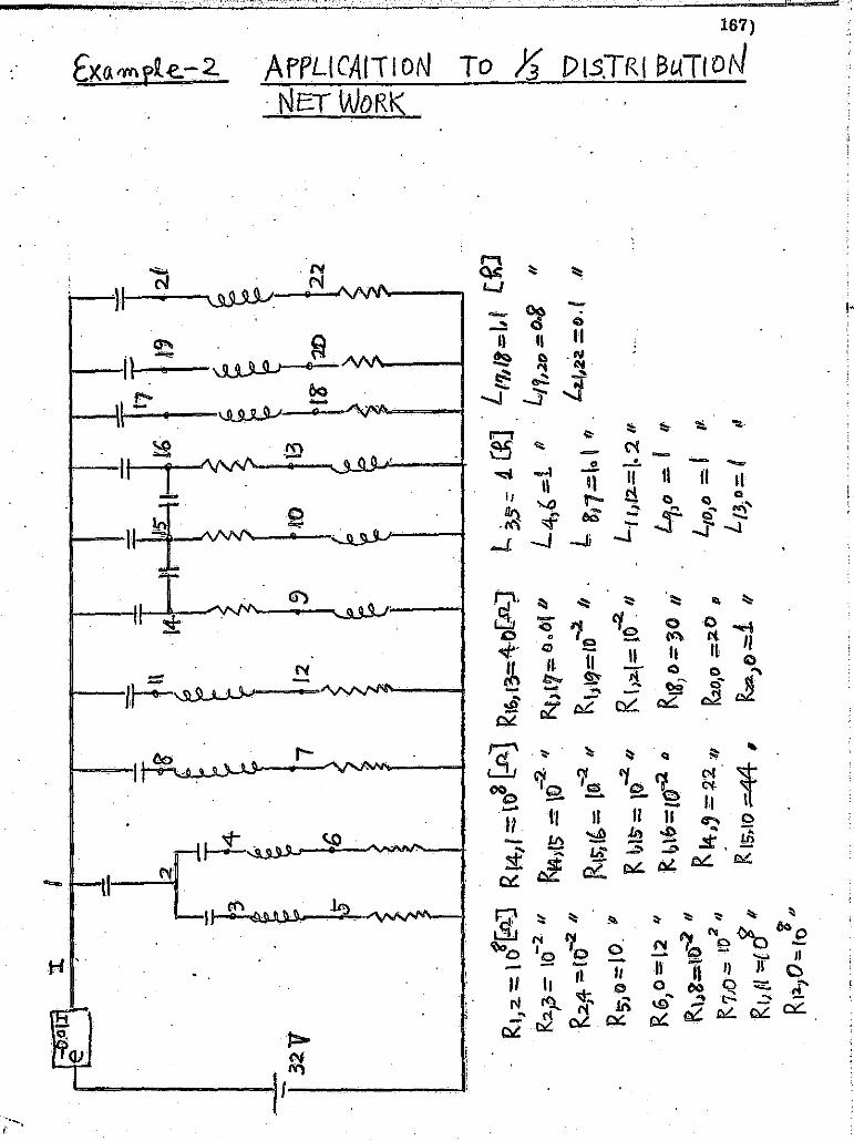
f~;.';
",~':
;'~'_;
~d',_'
~~" ,
_,-_:-~:::~:?";;:'-~~':'"::"~~'----=::-'~
I :
I J
-...
.;
1 1, • I I· Ii I' I I : ' , 4 ,
-
:r.
I
, r.ll 1
11
11
1
, !~
)l?
1n
LJu
~ p
1 T'
l" 3
T4t
. ~.
' ~
;, (
,1-('
I '. I
' . 2.1
3lV
7
/2
~
~s
6
I RI
,:z. ':
::; 1 ()
fr&-'J
R1
4,r :
:::l0
3!;A
] R
I0/1
3=4-
0[.$
2.)
R2p
= 10
-2 II
R.2J
4 ;: (
0-2
/I
RS'
Jo=I
O.
'/I
R6
,O=
l2
II
RlJ~
=H:)-2 "
f(
7;0
.:::
n:
/ II
Rl, (/
-;:::uJ
" R
FL)O
""f;
d
f)
-'-2.
;,
r'l
4)IS
= \0
-2
RI5
;I&=
tG "
171
-2
."
I' ~
15" =
10
It b
ib;:
10-:2
Ii
Rk-.,
=n
'" R
lS, 1
0 .=
:44
,
~h[7
:;::
9.6
., b
D
-~
"'lj
'~=I
O h
.
o ..:
a 1'
\ I }::z
.! = 1
0 . I
I
R 1&,) 0
= ~o I
i
. ~o
,o .
;;:;
2.0
,
6)0.
::1
II
~o
{3
£8'
T20
22
l3S:
:: :1
(~J
.' L,'M
1=I,t
(~
J
L4
,b =
1.
II
Lf1,~r
J = o.
g "
L /t
j7=
\o'
f/
. 4,
,2~ =
0. (
11
L.{ 1
,.{.2
= I.
2 II
''''
0=
1
If
,)
L,o,1
) ::.
1 L{
3.o:
.1
,
II. "
~
~
.~ ,....
~ f'J
.'»
z"\
} .~
1:
~.Q
0>
-
70
-\
17\
-.
0 2:..
-I
o .~
\J
- ~
7'
w ~
o ...
2:..
.~ -
1 , , , ,,1 , , , , , '-.~ i i J 1 j , I . j I .,
% h
...• M
Hz
'%&'1
,:4 ' "
@1I
2" '\"
v':wn
,'i
%9
" •.
'II, .
. ,~,,;. ;,
+);
""",
,,","
';"'>
"'"
·e,'
" .. "'
. "'+
I~il",,~
~~;'"\"'
;>1 ..
....
, • ...i
J,""' ...
. ,=""'.~~
. .:;.-",.~.,_·
.~"..:.=-c,,~"
c.., """
~..J
!

r , Ie
,
J."
~ , ,
, ,
r ,
': ,-': ;',".
r r r ! t· ~.
~: f;'
l ¥> ~ .... , t·, t.::
~',.
" (' ~"O
t""" 1";,
~/ ',I-" ~ .. ~ -".
Ii: .:'
f> ~;
~'-
;~
I,
~,
I k
~J"
u u 0 U
LI
LI f
1 I :
U I I I 1
I
U U U
iJ . -
LJ
u II , 1 I I I
MODE. OE$CRI PT( ON
MoDE.i ( 0 ~ t(OS)
168)
RIJ2. I Rb8 I RI~)'>I R1S",i6 J ' R\II~, RIJ/?, RI,(~; Rb..2.4
RII IS"' ttVe clo5e.d
.MODE 2. (0 . .;-~ t < 1)
R 1,;2, RJ ~3) Rz) tI I RI,ILJ. I Rlq.lt'" R,tj16 J R ') 1,/" I(tt" 16
R"l!; JRI,lb ,RIJ1j' IR'I;!.(are closed
STop
VDLTAq-e.S •
,
I

'1 ..
'I ~. "
~"' ~;.
~,~,
F !':
k
~:-: ~. ~' . . ~" . il·;' t,~
')' ~ . f'
! .'-,
II f:
I ~ f;
F I ~.
~ ~
~ 1:1
r' l If
It " ,:~ r: , lj~
1l !k r~ ~~-:'
[I
o o I !J
I I .
,
I I I
T'
U i
U r' Li
u i I d q , .-'i L
p .J
n -J, ~ ,)" .;.-"..
~!!
169) Example-2 state Equations For Each I'Iode
MoDE. L VOLTAGE SOURCE 0 VOLTAGE SOURCE 0 1
Ii MA IR I X = I DE NT II Y MiW,,-R ...,1 x,--_~ __ ..!r;"", . ...:.M.:..::A~T~Rc!'-1 .::.X_-=-----,I~D~Eo:N~T~I..!..T..!..Y_M~A:::r~R~I~X~ __
A MATRIX A MAii{1 X
I J AII,J' (NON-ZERO) I J AII,J' (NON-Z ERa)
1 1 1 2 2 1 2 2 3 :r 4 4-5 5 5 b 5 r b 5 6 is 6 7 7 5 7 b 7 7 8 8
ORIGINAL PAGE IS '1 J. BII ,J) IN-O-N-·iE-RO} B MA TRTVX-.......c...-.-romlii.,p;;.:;O~O<;;;R;::.Q""U,;:AL~. ~ITY~' .-~. ---. . -- -" - -.
__ ~ ________ ~ ___ ~___ 1 1 1. DODon 00 ___ 2 __ .. _1 __ ._1 .• 00DOOE 00
3 '.1 9. H:l9lE-)l ___ 4 ___ 1 B.H333E-n _____ ..
_-:-_~I __ J~· __ ~R~I~I_.!..J~I __ .!I.!.".l"NON-ZERD)
-,-__ :-1_~1 1. ):n:>:> E :> J 2 1'---";:9~ 9991'1 E';;O 1-
5 1 9.9999'JE-:ll ----_~Q __ l ,l.QOOOOE 00
7 1 1.25)J'E J) -:--------- _~,1t __ l ___ 9. J'}Q'IlE-Jl
9 1 1.25JOJE 00
__ ~:3;._~1 9.09091E-)1 4 1 9.13333E-)1 5 1 l.j»))E j) 6 1 r;;OOO-Cfj-E 00 10 1 1.9Q.O'Q1E..1L ____ ~_ 7 . 1 1.25000E 00
---8--1 -9;0909lE';"n-----·--~·
9 1 1.25»)E <» ---1"";0--1 l~QOOOOEn ...
-y------ ._-_ ... _-_._--------------- ._-------

~~~:~W:~':r
-'-;
~-"'
~~
"-.'.,
.-,.-,~~"",,,~,--
-r,
';"~
-~,
',"; r
;:>-
~~_~
r'<_
-~;{
\;-;
' .7
/:~"
"':
"~i:IF
;'-:" ;,<!~~7)'T~~"c;"i"~"~'f".'~.·~:W:~~~~~,~~f"!':~~~'tI'-~' "
~'-'
~:;:':
~'-" :%
', ~~"J."""_~,_,=~,~,_:,,,~---:-,,-~~=,~,,--=~__
_
r=:::
J =:1
r-.·,----~
,---
'---
-[:
0--
r'--
L..
.--
r .. -
-t
'-'
r'-
''''
'----
;""'
--'
r"~=
-"]
'~--
j
NO
De
VO
LT
AG
ES
AT
TIM
E =
0
.0
::>
1 O
.31
00
0E
0
2 ··--T-····0~-310eOE02---3---0.;3IeoeE-Ol
4 o
.3T
oo
cfC
a2
E:l
5 0
.0
..!>~
0.0
7
0.0
8
Q~3l00QE
32
--'9
o
:31
JJlE
J2
--1
) -).3D~OE n
11
o
-.ii
o·O
JE
02
1
2
Q.o
··
. ------~---------cl!i!
__
1.3
. 0 .
• H
OO
O'E
_O.2
__
H
0 •.
319J
I'OE
0
2
15
0
.3JO
(j)0
_L
O? _
_ l(,
O.31(j)Q:Q£....Q.2~ _
_ ~ _
__
__
-;-_
t:J
1
7
0.3
10
00
E
02
1:
1 0
.0
19
Q
.3lO
'QO
E
02
2Q
0
.0
OJ
__
21
_·_
0.3
l00
:I'E
0
2 ._
22
__
_ 0.0
_._
.,.
. __
__
__
__
. __
__
_ .
~
: ~lJ
,.__
II::
IE:_
~E~i
S TI
VE
C;
1)~g
E~'\
I!tS
._lI
T
T H
IIE _
T ~ _
__
0 .o
g
l'
2 @
.O
2 3
0.0
2
4 0
.0
5 0
0.0
0
6 0
0 .• °
1
8 0
.0
7
0 Q
. 0
1 11
)
• )
c::
12
:>
:l.)
1
14
-O
.21
24
4E
-12
1
4
15
0
-:1
%4
0e-Q
S
15
1
6
O.4
07
09
E-0
3
_ ~
_-:
-,1
1
5 _
_ 0.4
;l.3
J?E
-?,3
1
_1
6 _
_ -0.4
07
2'o
e-0
3 _
_ 14
__
9 _
_ 00
0
15
__
1o_'
__
0.0
.
l2:
16
.1
3 0
.0
1.
17
0
.0
1 1
9
0.0
1
21
:>
. ° . Hi
1
8
0 0.
:>
20
· 0
0.0
2
2
0 0
.0
. ti
l -
. .
_ ... _
-.--
.. _
--
-"
::>
NO
D'E
V
oL T
AG_E
.S
AT
TI
ME
=
Oo_
LQO
OltE
o@
_
.u u
_
.. §
. 1
O.3
l0B
lE
02
.
2 0
.31
08
2E
0
2
3 0
,.9
91
82
E-0
3
4 e.9
91
B2
E-0
3
:!<il
I 5
0.3
1:l
B1
E-0
5·
&
0.3
72
97
E-0
5
7 0
.31
07
3E
0
2
8 0
.31
07
91
: 0
2
·0
9
:l~-3H!>5{--ji
D
)~3B617E:lO
11
O
.10
22
3E
':'0
2
12
@
.2i9
HE
::"0
4
,: ~
l 1
3
Q .• _
2139
'9E
_Q:
J __
U
0_
.31
05
4E
_fl
2 _
_ 1.? _
_ 0.3
10
ME
0
2
16
0
.31
0],
OE
0
2
: <:
j
17
0
.31
07
2E
0
2
13
0
.29
03
3E
0
2
19
0
.31
06
8E
0
2
20
0
.28
51
0E
0
2
,··,
0
., 2
1
0 • .
J.ll
t51
LQ
2 _
_ 22
:l
.31
0lt
J'L
02
'
l:3 . ' ....
. •
I .....
~.I......l.HE
RE
SIS
TIV
EC
UR
RE
NU
_.A
T3
IM'E
T=
___ .
_O
.lO
OQ
OE
QO
_:..
. _
__
. __
__
. .-.f
.J 1
2 ::
>.5
2162
E-0
&
2 3
0.3
10
81
E-0
6
2 4
0.3
10
8l.
E-0
6
5 0
0.3
l08
1E
-06
' IC
il 6
. °
0.3
10
BIE
-J&
1
8 0
.31
07
3E
0
0
7 O
O.3
l0
nE
O~
1 1
1
l.3
UB
IE
-)6
, b
12
0
).3
DS
IE
-n
--l -
-1
4-0
.28
11
3E
-Q
9
-'1
4--1
5
25
49
EO
i-1
51
6-0
:-3
:nt"
7E
-OD
:,1
:;l
_--
:--.
1 _
_ 15
O
coI5
'j'}O
E_'
ol. _
_ 1 _
_ 1.
6_. _
J).
11
64
6E
_0
1
14
9
. O
.•. 1
25
49
E_
O_
l_·1
.? __
tO
0_._69727U_~~
16
1
3
O.7
71
ftO
E
OJ
1 1
7
0.'
}6
77
6E
OQ
1
19
Q
.14
25
5E
Q
1 1
21
:I
.31
04
7E
0
1
.:.-
18
0
Q.9
Xr.
76L:
lJ __
?~O _
_ 0 _
_ 0.1
42
55
E_
OL
_2
2
Q
:).3
1;)
47
E:H
'
!§
NO
DE
VO
LT
AG
ES
AT
TIM
E
=
0.2
00
00
E
00
.
..
. : !~
1
0.3
TJ8
5E
-j2
2
0:3
10
8%
O
Z ---3
---O.liz07~-Q3
4'0
;12
-20
1E
-03
.•
~
5 @
.31
0B
5E
-05
&
O
.373
::l2
E-O
'5
7 :I
.31
08
2E
0
2
8 O
.3L
J82
E
02
9
O.3
8Z'Z
3E-:
i"j
D
O.5035·4E':02--1T--o~r3:73-~E:-03
12
0
.2
79
76
E-0
4·-------------'
I 1
3
0.p
B5
3E
=0
<!.
__
14
O
.31
05
4E
0
2_
15
__
0.3
10
68
E . .
m2
_1
6 __
0.3
10
73
E_
02
__
~ _
__
__
__
_ I
17
O
.31
07
5E
0
2
18
O
.30
94
1E
0
2
19
0
.31
06
9E
0
2
20
0
.30
8S
9E
·02
) _
_ 21
0
.31
05
4E
_:>
2. _
_ 22
__
0.3
10
54
E
02
__
__
__
_ .
-
----
_ .. _
--.--------
i --
-t ,
... ..., o -
._--
-.--
"" ---
--.... ,
ihh,
-¥ri
j77&
~t~:
~;p0
:~:-
·-;~
:7~:
:::;
~.·;
;;;,
:;;~
j~'~
":::
;;,d
~'i:
':'~
':~·
::;-
;~,~
·'¥_
@-,~
;,;~
~~',
~t:~
~·~~
' :_.:~
~w., ,~
"~~~
~~j~
~~-~
;_·_
.. _._,~",
:{~~:~:.
.",.._..
.:..,il-
:-.:._..
..:,,,.:
'_0
.. ,'.
'
.1 , J " ., I ~

f~~~~:
;;_~;'
:;~~;'
;!Oi';
"~';':
~~=:"'
'''''.
· .=~
_~',:,
:,'::'
~::~:~
~:':==
,~.~~:
~,:'~=
~:::~_
w~,~",
:'7'~~
"C"~~~
':-""'
~"''''
':=~:J
.j
i'A
'!
ti' \ .~ I'
I~¥:
:'~
~--'
-:"'
';''
;''1
..
"~r:,",l
.,,-..
,,~..,
,_""
,,-=,
,1
, . .
.-."
_" It··'''''''' ,'
<I
I<~=
_";:
"'--
=-0
*' .• ~
, •. ,
-j
r~"'
-J
r'" ,
,...
.,.~
z::
:.:::;
~---.,;
OJ;'
''''
' ~
-..
!::::.
: '-
--J
~~ . .:'!
.-::
!~~~J ~
Ic~
bir
l
1--4
-L-L
-TH
-'E-R
-E-S
-f-s
r'IV
E'
CU
lRR
EN
TS
AT
' T
IME
T=
0
.20
00
0E
0
0
--.
.. ,,'
I
2 o.
S,·
21
69
E-J
6
' 2
,3
0.3
10
a5
E-0
6
2 4
a.3
10
85
E-0
6
sci' 0
.31
08
SE
-06
b
0 J.3
f:fg
-5e::
:j{
;--1
---a
--:r
;'3
1:l
82
E
0:0'
7
Q
O.3
1J·
82
E
do -
-r-1
I-:j
'.3
10
8S
E:'
O&
-
12
0
O.3
10
65
E-O
S,
1 1
4
Q.3
05
11
E-0
9
14
1
5
-Q.1
39
42
E
01
IS
1
6
-O.4
40
72
E
00
1
15
b
.13
5'J
4E
3l
1 1
6
a.1
21
75
E al
14
9
0.1
39
42
E
01
IS
1
0
0.7
05
98
E 0
0-,
-lb
. 1.
3 O
.17
67
7E
O
J 1
17
@
.10
31
4E
0
1
1 1
9
O.1
54
29
E
al
1 21
O
.31
J54
E n
rs--
J
).D
31
4E
n
-2
:>--
J :)
.15
42
9E
el
l ._
-2
2
a O
.31
05
4E
01
NO
DE
VO
LT
AG
ES
Arr
iME
=
0
.30
00
0ro
o
1 0
.31
08
% n
2 a.3
10
85
E
02
3
0.3
0S
18
E-0
4
4 0
.30
S1
8E
-a4
---'5--:>~3D85E-J5-
r,"-
J .3
73
J2E
-05
7
0.3
10
B2
E
02
-, 8
0
.31
08
2::
0
2'"
--,---
9,
0.4
24
35
E-O
l 1
) 0
.91
55
3E
-04
11
a.6
Hl3
5E
-04
1
2
0.
21
97
7E
-04
-~1"';3--0;61035E-04 '
-14
----
--0
.31
05
4E
0
2
15
0
.31
06
SE
0
2 -
16
'0
.31
07
32
Q
2 -----,-------,---
17
0
.31
07
5E
n
18
0
.3l0
'66
E
02
1
9
a.3
10
70
E
02
2
0
0.3
10
52
:: 0
2_
-'-_
__
__
__
_ _
---"
;21
:r
;;3L
J 5
ItE
-n
--2
2--
J.
31
) 5
4E
n'-
·
~.
lIC
L'I
FIT
RE
SI
ST
I V
E'C
fJiR
RE
NT
rAT
TI
M;E
: T
= --
O.3
00
00
E 0
0--'
1 2
:l.6
21
70
E-J
'!l
2 3
Q.3
1Ill
SS
E:-
0;6
2 4
0.3
1Q
SS
E-0
6
S :>
).3
l)B
SE
-J('
--'6
0
' --). ~D35E-)6· -'-
~'i
8:>
.3lJ
S2
E
00
-'1
-~--o--o. 3
10
82
E
1110
---
--r '-
n'-
-:r
:31
J9
5E
-J&
-1
2
Q
O.3
1:J
S5
E-J
5
1 1
4
0.3
'07
69
E-0
9
14
1
5.
-0.1
40
96
E
01
15
1
6
-J.4
45
90
E
00
1
15
Q-~H59'SCJl
1 1(
;--0~'f2227E-Oi
14
9
'O.1
40
96
E-o
i--1
5
10
J.7
05
iJE
-OO
-1
6
13
O
.77
69
ZE
O
J 1
17
0
.10
35
5E
: 0
1
1 1
9
0.1
55
26
E
01
1 2
1·
,).3
1lS
ftE
II
-----.I
S--
)--J.I
H5
5E
H-2
:>--':
>--O
.15
52
6E
0
1--2
2--0
--0
.31
0S
4E
0
1-·' -,
, .,
,,--
-lmN.
O""D
E VOLf~-AT -
u ME
=--~~;4(f(fOO E
-O;O
----
" 1
0.3
10
85
E:
J2
2
0.3
10
SS
E
02
3
0 .• 3
0S
1S
E-0
4
4 0
.30
5U
E-"
---~5-=--'a.~n85 E
-j
5 b
J • n
'3 j
21
0::
-:1
5--
-7--
--0
.31
0 a
lE
02
a
0~'31,0~fl~2FE ~0.,;'2r-·----------
9 0
.47
S.0
7E
-OZ
. 1:
> 0
.0
11
0
.45
77
6E
-04
1
2
O.2
79
77
E-0
4
--"130-;45775E';;04--n--O~3H)54E-02---1S---0.3106SE02-r6---"0.31073E' 0
2---
17
0
.H0
75
E
92
1
8
0.3
10
74
E
02
1
9
0.3
10
70
E
02
2
0
0.3
1D
68
E
02
2
1
J;3lJ54E')2--22--'.3l)54E~02
--~.,...--
lIu
TH
E R
cST
ST
IVE
C
UR
Ri:N
,rs
AT
'lIM
):
T":
:,.;--
-nO
-.L4n 0
0"Oru
OruE
"'0
"0
.,---------'------,----------
1 2
O.6
21
7D
'E-J
!l
2 3
0.3
10
S5
E-0
6
2 4
0.3
1:l
'8S
E-O
('
5 :>
).3
l)B
SE
-J('
-'
----
;-6
-=--
-xO
-)
.31
)3S
1:-
:")6
'-'-
I--8
--:)~-31:l82EOO-"-'l-'-O
ir.3
'10
82
E 0
0--1
---1
1
:l.3
1JB
SE
-!)'
6-'
1
2
0 D
.31
03
5E
-:lS
1
14
O
.30
79
8E
-09
1
4
IS
-0.1
41
l3E
0
1
15
1
6
-D.f
t46
47
E
00
....
1
IS
o~ 1
S'7
10
E:l
l 1
-"1
6 ...
. ---
0.1
22
33
E 0
1-1
4--
9--0
-.
14
11
3E
0
1 '-1$-lo--~:l~'70blOE' 0
0-;
::
16
1
3
0.7
7S
92
E J)
1 1
7
O.1
03
58
E
01
1
19
0
.15
53
4E
n
' 1
21
).3
1)5
ftE
:n-
I 1
8
0 J.I
H5
SC
H
2j--'J
' 0
.15
53
4r:
-ln
2
2
0 O
.31
05
4r1
ll1
..
---
--.;
"''''''~.
',,1
. ,_
'.-_
_ .'
-"'_
.' __
,,,
H't¥
Hhfrl
'i'!r4
6wji!J
t,"V'
iZ:.t
: tb
't#
"6¥
rliF
v·
; j"
;;';
', ,
;. ..
. ~.""6i
;"'""i
~;"",,
, .. f
. ,,!
.alii.
' '~-,j~
'*t ,: ...
. ,.,
"',.
, ...
......
.. ,L· .
... "'~'
"'~~~~
~~'" ,_
c.c
~ ,.
'i ,I

\:!-: ~~:;,~ ,.'
If
'--~'--
.. -... -"
"! "
-.
. -",
_,,_
J
~.'~
70;:
;-i!
~:-'
,.~~
-i~:
~~:
--,;-.
"" ),-
--;-'1
'. 1"
/"'"
'-~"C'''''-''~~::;:~~~.~'':;'"T~;<;''~f'''''"'f~''"''''''!''''~:r'''!~?'''~~''''T;::l~?~'''''''>:''',~~"' ..
. r:-"'
7 -F
"""'
~~
, __
~~= _
__
=~_=_~~""==="""""""" ...
." ...
......
. ""_._"_
-_ ~
SJ±
GS
SW
SV
",,,,4
B!I&
i ..
il'l,
,_ "-'~'ct_,
",
'~.,
. ,,
,',~
,~~~
,~~.
. ==
-.~
*P-,
---
-=
"=
.. =
,W,U
==
_=
~.=f
Lf
1L1
lriiii
i ~
f '·
",,
'l
", .. ~~_1
I-'~
i,,,,,,,,··_~
t~l
t-':
J
r' .... ~1
.-.-
----
/ ~
-.~--
L-.
..-;
~,~,--!
["'-
] 1':
::::1
::
:;:;
~j .
NO
DE
VO
LTA
GE
S
AT
TIM
E
=
o.s
mn
nrC
l!lU
0
2 1
O.3
1_08
5E
n 2
2'_o
}_lO
S5E
__ 02
3
O.}
_05.
!8E
-Olt
It
0
• .3.0
51 _
8 !:-
:Oft
!i6
t: 5
!l •.
31:J
BS
e-=
:r5
6 :J
.37
3J2
E-0
5
7 O~1082E02
8 a.
31
0B
2E
0
2
~
. 9
O.5
95
09
E-0
3
10
0
.0
11
0
.45
77
6E
-04
1
2
O.2
79
77
E-O
lt
c:: ~.
13
0
.45
71
!.E
-Oft
1
ft
0~3T
o5lt
E 0
2
15
O
;3T
06jj
iE--
02
16
0
;31
01
31
00
,2
~ C
j)
~?
~_~~
g~~~_g~ _
_ g __
. _~:~g~~~
__ g~
19
0~
~10J
[)~0
2 __
2J
O.}1
:H>~
E __ ~2
a: ~.~
O<
f.!:
j
1\[
[ TH
E R
ES
rST
lvE
--C
Oim
Ef'
j..l
"SA
rTlM
,E
T=
O.5
0CH
!iOE
-OO
1
2 O
.&1
17
0E
-06
2
3 0.31085£-~.
2 It
0
.31
18
5E
-06
5
) J.
31
)85
E-J
6
6 0
l.3
T:f
8s-
F:n
, 1
8-·' -
-o.3
TO
l3'2
E-O
ll-'
0
0.~ne'B2l:-oe
1 1
1
:1.3
10
!l5
E-0
6
12
0
1il
.31
09
5E
-J5
1
lit·
0
.30
80
1E
-09
1
4
IS
-0.1
41
15
E
VI
15
1&
-O
.ltl
t65
3,E
0
0
1 .1
5
O.I
Hll
E-n
1
16--Iil~r2234E-Ol-:--l'4
9'-
-0;1
41
15
E -(n~5--10--0'-70610E' 0
0-
16
1
3
O.7
75
gZ
E
OJ
1 1
7
0.1
03
58
E ~l
1 1
9
J.1
55
35
E
01
1 21
).
31
)54
E
)1
--'1
8
::J JolH58E-n~O-·-0--0.15535E
or-Z
-2
--0
-,-
0.3
10
54
E-O
l -------.
NO
DE
VO
LTA
GES
A
IUM
E =
1
il.6
00
tiH
I"'E
""C
il"0
-------------------------_
__
_
1 3
.31
11
2E
)2
2
J.3
10
HE
J2
3
0.3
10
62
E
02
It
0.31
0-&
3E
02
--'5
0
.r7
10
'8E
'02
5
0-;
;19
17
2£
02--I--O~31nOE;;;04-· -a--o
.2
lt1
l9
E-lIZ
---------
9 0
.16
5,0
2E
-Ol
1:>
0.8
19
40
E-0
2
11
0
.24
71
9E
-02
1
2
0.2
79
99
E-0
4
13
O
.72
78
4E
-:'0
2
14
O
;'3
11
01
E0
2--
1'S
---0
.31
10
3E
-0
2-Ir--e.3
1 L
J4
E-0
2----------
17
J.3
un
E
J2
16
).
3lJ
9JE
n
19
0
.31
09
7E
0
2
20
0
.31
0S
ltE
02
21
Cil.31::r8T1:;-0-2~-2
0.:
31
07
71
:02
-----
AL
L
THE
RES
I sn
VE
-ClJ
iR'R
-EN
TS
IIT
'TIM
E-T
"---
o;-
60
O'O
OE
OO
----
----
----
--,
,,_,
-_, _
_ _
1 2
).3
3)8
5E
,)l
2 3
J.1
71
0'B
'E
01
2
It
0.1
59
77
E
01
5 0
O.1
71
:!S
E
01
6
0 O
-;-I
S'l
77r;
-Ol
1·
-s--
cr;3
1110
E:;;
'06~
----
--r
0 0
-;-3
11
10
E';
'06
--r-
n
O.3
nro:
e;;o
o-1
2
0 0
.31
11
0E
-J&
1
14
0
.1l5
69
E
IH
14
1
5
-0.2
55
9.7
E
00
1
5
16
' -J
.:'>
l79
3E
-(1
l 1
15
0
.'IO
JS8
EO
J 1
16
0.8
3'r
tfE
0
0
14
9
0.14
1291
: 01
1
5
13
).1)51JE~-
16
1
3
J.7
77
41
E »
i. 1
7
0.1
03
63
E
01
1
19
0
.15
54
2E
01
1
21
).3
10
77
E
01
T
Il
0--0
;1:>
36
3[-0
1-2
0--0
--0
.15
54
2E
Ol-n
--0--0~31077E V
l-----------·· -
----_
_
NO
DE
VO
LTA
GES
A
t-T
IME
: 0
.70
00
0e cfo
------
----
-'-
-------_
__
__
__
__
_
1 J.
31
12
5E
J2
2
J.3
D7
7E
0
2
3 O
.31
05
1E
0
2
It
O.3
Hl5
ltE
02
~-
"5-=
----
-;;0
.25'
l2lt
E02
5 0
.2-7
41
11
:'0
'2
7 0
.3l:
T2
5E
-04
8
0~86
915E
-0',
;-3=
----
----
----
;-\
9 O
.70
3't
3E
-02
lJ
O
.28
B3
9E
-02
1
1
0.8
54
49
E-0
3
12
O
.28
01
3E
-O'>
\
!:i
:.1 :J ,J
II :1 , J , 1 ~ I i ;
.'j ~ ~ l j '1 .~ 1 ,1
D
O~'25482E..;02--H--O.31115E 0
2--r5
---0
.31
11
7E
-O
Z-1
6--
O.3
11
18
E
02
""
-1
7
O.3
11
16
E )2
_B
__
J.3
11
11
E 0
2_
!? _
_ O
.31
11
1E
__ E2
__
2~ _
_ 0
.31
10
5E
02
.... j .. ' .. : ...... "
21
0.3
10
95
E
02
22
O.3
10
94
E 0
2,
! -.
I 1 .'
• !
. ;1I1111========~~~~~~~~~~~~~:=~~~==~~~~~~~~~~~~~~~~=-~~~~~~~~~~~~~~~Mu,
--f
if"
'5:&<
if.
-'.
'Me
t"
,-,;
,;;;
--,,
-z:y
; "'
i>
-Odl
lol'"
,--·4
,;
........
,~,.o."" .. "_
,'_-
-'.,
,..~
...
7[
1; S·
,rtU
.;g;:;
g:,-4
m·"6
--;; ..
4Wet
riiu4
P;9;
·,F,"-
"·, i
t-··
:-"J
"ii2
;, "''i"'-'~~M·<·';';#~UItt
" ~

r~;,~"
F'''
''~'
''''
-",'
, ·~-~·-=-:-:c
-,."
.. ~_,
~r"'
."'~
:·:-
;.~:
~~Fr
~ .. ~K.fT""·"~' -
':1-
7 ~.
'-,y
:c··
T'.:
:~~~
~;,,
~~~~
-~'"
·~:~
,:
5#",
t~ Q
i.
Gf,~
."r-~~~f""~~~"
~_~t:
.. .!c,,
;"
;...
_,_~
... -'.
~ .• _
,-, ,"
J: ..
~l
CZ,~
iUat
_~:
:<!~
."_L
;,*"
'=
w'"
-j
Wii,
1 I~
''''
'''-
"I
'-":
-"e;
~~
p=:.
.:."
,"
"'""
-.,
."....
.--=,
,1
i, • ...,
...".""
.,..j
..... --.
'-~"1
,--
c-~
.------
t
'---'
,-
~'
[ c:
::::J
I
! :""
"' .... ''''"
1 ~
" "-1
! l. ! I I I I i I I
AL
L
TH,E
R
ES
IST
IVE
CU
RREN
it'S
AT
TIM
iEr=
e
.7
00
""(t)""O
J:"E
-O
"'!
)...-------------------------
1 2
~.!tBS21E
II
2.
3 0
.25
92
4E
0
1
2 4
0.2
28
98
E
01
5 ()
O.2
59
2.4
E
()l
6 0
0.·~2398F-:ll
1 8--g~"31T2'5E";06-'
t a
a"3
U2
SE
-'a6
--T
n
0.3
11
2S
1:"
':)(
'--
12
0
O.31125E-O~
1 1
4
0.l
lS1
BE
0
1
14
lS
-O.2
'S6
20
E
00
IS
1
6
-:J.019~lE-Ol
---,I
----x
S
O~')Jl48E:JJ-,,--16--0.B3974E
00
.~.1t--
9--
---u
.14
14
0E
n
-IS
-lJ--).1
J7
14
Fn
-.
1&
13
:l
.H1
88
E
OJ
'1 1
7
0.1
03
10
E
01
1
19
0
.15
!>S
2E
01
I
21
O.3
10
94
E
01
1
8
0 0
.i0
37
0"E
-n
20
0
O;1
55
52
CO
l 2
2
0 cr
.31
09
4E
-Ol
.
NU
DE
,7lJ
ITA
'[;;
F5-
AT
T
i ME
=
Q~8UOOQF1JO-""'--
.. _--_
._
-------
1 D
.31
13
1E
)2
2 O
.31
07
7E
0
2
3 .
Q.3
10
47
E
02
.4 O
.31
QS
2E
Q
2 -------
.-
....
_._
--_
. __
.•. _.-.... _-_
._--
_ .. -
._--
_._
--..
_
._
-------------
__
_ S _
__
Q.2
91
63
,E
02 .. _
' _0
. __
0 •.
2991
SE
_.Q
2 _
_ .. 7
__
Q.3
1.l3
'OE
-_0.
4 a
._Q
. 3
3 5
69E
.-03
. 9
0.2
5!>
3S
E-0
2
10
D
.9'l
1B
2E
-03
1
1
Q.3
35
69
E-0
3
12
a.2
80
17
E-0
4
__
.A.13
__
_ 0.9
0n
7 E
:-.J 3
_1
4-_
_ ).
31
11
'lE
J) 2
_1
5. _
_ 0
.31
12
2E
.. 0
2
lc6 _
_ 0. 3
11
22 E_,,)~2 _
__
__
__
__
_ _
17
0
.31
12
0'E
n
19
l.
31
ll'l
E
02
1
9'
O.3
ll1
5E
0
2
2Q
O.3
un
E
02
_
_ .2
1 _
_ 0.3
11
Ol'E
()Z
. _
.22 _
_ o
. 3H
)9''l
E ..
02
__
.. __
_ . _
_ . _
_
_ l,
\lL
.J'H
E_
RE
SIS
TiV
E ..
CU
RR
EN
rS ...
AT
TIM
E
T=
....
. O.B
OO
O:J
'E
OJ
__
._. _
__
. 1
2 l.
5 ...
1 ...
3E
Jl
2 3
0.2
91
63
E
01
2
4 0
.24
97
9E
01
5
() 0
.29
16
3E
0
1
6 0
0.2
49
HE
01
·1
8
0.3
11
30
'E-0
6
7 0
Q.3
11
30
E-0
6
1 n
0.H
13
0E
-06
--
-':-
1-"
'2--
0'-
-0.3
f13
0E
=-0
f>--
1'-
-14
--(i
.-U
SB
lE-O
l 1
4
IS--
:-@~
2S
63
0E
0
0
15
1
6
-J.&
fS'f
IE-)
'-:'
l~-:
---:
-l~-
g ~:
;~g~
~ ~~
-. -~
~~
t~~i~~~
g~
Ii 1:
g:!~
~;~~
g~
__ l~ _
_ ~~
__
g:~~
~~~'
~_~~
__ .
_--
,18
. __
_ 0 _
_ 0.1
03
(3E
0
1_
'_2
0
0 0
.15
55
1E
Ol_
.. _2
2
0 0
.31
09
9E
01
---..NQJ~I;_J'-OLI.~;;_ES_ A
T T
IML
=-_
_ O
.• ':
10:J
:llE
_JQ
.------.--.--
c;:---;-
1 0
.31
13
2E
0
2
2 0
.31
01
6E
0
2
3 0
.31
04
6E
0
2
4 O
.31
0S
1E
02
S
(i).
3035
... E
(i)
2 0
(i).
30
12
1E
0
2
1 0
.31
13
2E
-(i)
4
8 a.1
37
33
E-0
3
--'9
--0
. 9
30
HE
-03
l:
l O
.35
09
'5E
-03
1
1
1!l
.13
73
3E
-03
'-li
.. -
0.2
80
19
:-0
'" -
-----.--,
_--
-;1
3 _
_ ::
l.3
5H
5E
-B. _
_ 14
__
:>
.HIl
IE:>
2
15
0
.31
12
3E
0
2_
.16
__
._ 0
.31
1Z
"'E
02
::
17
0
.31
12
2E
0
2
IS
l.3
11
l1E
0
2
19
0
.31
11
7E
0
2
20
0
.31
11
6E
0
2
3 2
1
0.3
11
01
E
02
22
(i
).3
11
01
E
02
~
i --
-._
..
--
_ .. ~-
~ ....
~ ~r j
; ':~
L~,
'.'~ tH
Hrb§
!t
k·J!
;;;:
j,,-i
;'ffi'
1"d
4h
y-·'4
**0
:iit
",·-
sf¥i
rii5!
;6W
.... ~;'
: 4;;-
.;4-~~~.{
H
'-ih
"(
,r'
d;i.?~
&::f
ii~·it
8f w:
" '-*i
,~ . d
,;;"';
;,.::i
Li:~~~
~';";'
'';'.:
:.~","
:.;; ....
..... ..!~
·;'''''''uw,
-,,oi'_:. ~
.. :~..
,-::.'""
'--~

¥._
'\.'l:C~$,;"
,,"'
" ,.
'.."
'''
Y"'~''
'' ~,,"
•.•. "
,·..·
T·"·
, :;~".
~~;;,"
" !f!<"
;" ",,,
""""
""Y'''''
'''''':~
T'''\~''
'=''''''
'''i~, ,:"
,:,.,..,
W 'f!
"""\W
M ""~
iT I~''
:''''~
<~'-''
'~ >
F
.'
e"."C
C'""
,"""'=
i., .",
,-~, .. ,~,
,,=,,.
,,=,_,
,,=~,,
,,=,=,
,,_."=
M.="_"
4=" "
-_A
A".
=a
"' F
" ,_
"".-
y
!.~
1-=:
1 r=
::J
r~,
r==~
[ ."
L_~:
L_~J
1_
__
,_~
, !,~.
.: :--
-J
L -'1
C""
"\ r-
=1
r..
::.:1
r'~;.
'=I ~~
q
4L
L
THE
R
ES
IST
lVE
CU
RR
EN
TS
A
T T
IME
T
=
a.9
ao
oa
,E
ao
--·-1-'-'2--"'1l.55~5~E·Jf-'2~'-
'3--
-e;3
03
54
EO
T'
2 4
0.Z
56
06
E of~ ~5~-" O-~ ~O.30354E 1>
1 6
° O
.Z5
50
6E
3
1
1 a
0.3
11
32
E-0
6
7 0
0.3
11
32
E-0
6
I 11
3
.31
13
2E
-06
---"71i--0--O.31132E:'j~;--i--T4·'-aoll"82E
01
1
4 -
lS'-
--O
.25
63
3E
0
0'-
-'1
5--
16
-)
.&H
:lZ
E-:
')i-
1 1
5
::l.
'1Jl
77
E:J
J 1
16
O
.B3
99
9E
0,
0 1
4
9 O
.14
14
5E
01
1
5
10
O
o1
07
34
E
00
1
6
13
0
,77
a:)
'JE
-oj
1 i7
C
i.l0
37
4E
-QI
1 1
9
0-~-i5558COl
1--
21
0
.31
iolE
-ci-
l-_
_ J,
8
0 _
__
(jol
037l
tE._
C1,
l __
2
0 _
_ 0 _
__
oo
15
55
BE
0
1_
2,2
__
_ ,O
__
_ 0.3
1l0
1E
,01
____
_
NODE
V
OLT
IGES
IT
TI
ME
=
O.I
JJJJ
E :
>1
T--
-O.3
11
33
E
J2 ---2
--' O~31076{ 0
2
3--(i.3iC')46E-02---4--"0~'3'io51E02
5-0
.30
79
1E
0
2
5 ,O
.30
95
3,E
0
2
7 O
.31
13
3E
-04
8
' 0
.91
55
3E
-04
---9
f--, O
.j3
55
9F
03
1:>
O
:TZ
Z0
7E
-@'j
'--r
r--0
.91
55
3E
-=-@
/t
12
0~iB02-0E:-04~--~-------
13
O
.15
25
;E-J
3
l'
J.3
11
21
E
G2
15
0
.31
12
4E
0
2
16
O
.31
12
4E
0
2
--:1
'r--
-ci.
31
12
3E
O
Z-H
I--0
.31
12
2E
0
2 -
19
--0
.31
1l7
E O
Z-2
0--0
.31
11
7E
0
2'----------
21
0.3110ZE_g~_32
(j.3
11
02
t:_
02
. __
__
"--_
_
lilL
TH
E
RE
SIS
TIV
E
CU
R'R
EN
TS
AT
TIM
,E
T";
G
.IO
OO
O'E
0
1
1 2
0 ~ 5
&:; '
8 SE
'''5
1--
2-
3 O
. 30
791T
0:-:1~'---=2--4-:----:0=-· .-=
2:-::5
""7;::9
"'4'"=
:E--=0
7 1----: 5=
----
=0
=--
--=
0-.
=-3 0::
7::9::
1"'E~0
""1'-
6 0
O.257~'E
01
1
8 O
.31
13
3E
-06
7
0 0
.31
13
3E
-06
1
11
0
.31
13
3£
-06
f2
0
--O
.31
13
3E
::'0
!>
i-~f"[email protected] -o
C--
--v
.--f
s
oO
';2
56
35
E0
6--
15
--1
6
-:>
.!>
H55
i:';;
}-1-
1 1
5J.;)l3
JE
)J
1 1
6
O.8
4:l.
:J2E
O
J 1
4
9 0
.14
14
6E
01
1
5
10
J.
70
7.3
5E
0
0
--,-'16"--~13--0. H
all
E O
J--l-
-1
7--@
.10
37
4E
01
----r-I'i
--O
.15
55
9E
'OI--
1--2
1
6~31
102E
-0
1-
18
0
O.JJ37~.E
01
2
0
° O
.15
55
9E
"Ol _
_ 2.Z
0 0
.31
10
2E
_()
I,. _
__
__
__
_ _
~~
'.bilf
. ~§
l
l~~·
Ii:)
i;ij
"f;J
,
... ;j;! --
~ .L~
d ~ I I ! '\ 1
1 .-~ 1 I I ~ ,1 , ! .. j ~ ! \ I I .j I
r,,:
.'.'
->l.
;.',
-
"'I .;.
rtf](
'q' 7
*4# ft
' i
'j'$,
,,;i#
,,+ •
.. "'H 6"'i
" ...
' .. ",
;;""~w
;;;, .. ;
· 'de ."
.. , _
_ """'
.;.....J
:,~.~.JI
.,;1;,w
..... ·
i 'W
"'" m
' •• ·;
,·",
· j,
.... w.:
""""""~c,,
""'.;c...;
.:..-.. -
-.. ,,"'
~·, .J

f'1 l .
U
o u [J
I I
,J
I :] 'j I I , I I ! • ! !
i , I
! I L,
175)
REFERENCE
1. Stagg, G. W. and EI-Abiad, A. H. i "Computer Mehods in Power System Analysis .
MeGraw Hill Book Company.; 1968
. !.
I I "I •
1
-~- _.- ---_.

,
I ! i
rJ
II n L ; I
! .
III •. 2.a Combinatorial Method
2.a.l Preliminary
Consider the Electric Power System described by
equation (5) of section III.!. Assume
single-input system, and j (:r,,) :: O. for simplicity a
Then • A't; B,1.L, 0- - -+ -~ - Cg..
and
"D" :;: [B : B : '0 l.l~~ 1 .0 .... I I l!. I .D3~ l.(.;;.i is the measurable output vector ['1,~ ... l
where
Assume that faults occur due to openings of some relays connected to loads. The problem is to detect faults of the system an.d to find their locations from the output measure
ments. One can detect faults simply by comparing the actual
outputs with all the combin.ations of possible fault-outputs.
h ' th d ' rn , f 'l However, t J.S me 0 requJ.res ;;l,. comparJ.sons or a s·J.n.g e
176)
measurement output. In the case that one could measure r-outputs, the number of comparison can be substantially reduced to
where 1\. .. is the with outputs Z· I-
~, ~.
1 z, ~
"-:s 0 C>!
I./r +! VI .-I
£. ~ 71~ irl
number of loads
; Z~ =- ~1+1- di ~3
in the (see
~i-fz .. ~ +Z3----
~ I\- .
S C> ~ J: w
-0 ~ f
<"t "" I "T
Fig. 2.1
~ .. tZ. group associated fig. 2)
~LTI
f Zi. a... ::s
* 'f'.{ .~
I
, .,
-1

l I.
n I.J
!J n : .J
i I
2.a.2
The program consists of main two steps .• . (1) Partition the original system into NG Groups.
For each Group find the ideal steady state load
currents (2) For each Group assoc:'..at~ld with the corresponding
. output, firid all the possible faulted outputs in
each Group if some faults are indicated in that Group and compare them with the corresponding
actual output. (Refer to flow chart.)
As shown in the accompanying flow chart ·(see also the
program listings), the FAULT Program consists of two major
subroutines FAULII, COMET
(i) Slibroutine FAULII (N,. A, NG, Yact, LL, AL)
Inputs:
N: the order of system (the number of loads)
NG: LL(K):
the number of partitions the number of loads .i.n the K-th partitioned GrouE> (K=l, 2, ••• ,NG)
AL (K), the k~th ideal load current. .
k=1,2,ooo,No
Yact(I): the I-th output load current flowing in. the I-th partition.
Outputs:
A(J)=AL(II+J), the J-th load in the rr-th partitioned
Group. YIDEL(I) , Ideal load current flowing in the I-th
partition.ed Group.
(ii) COMBT (N, A, Yact., INDEX)
Input:
N: the oro.er o.f system
A(FAULII), Yact (FAULII)
I fl

, I
I : 1
i I , I
,
,
FLOW OHART
t= !
fARTiTjD'" I He.. o R.I q-(tJ A L
SysTE.M INTO
Er\ J q-2. ) .......... JEt-N9-
qL iB ~
CHEeI, fAll L-TE.O LOAD FOR q-i
. . i ~.t.~.v+
L~ Nff'
Mo ye~
s1°f
178)
,
I
-
,
'I
I j J ,J J .~
~i
"~l"'.·'.·.·····'·:.· • '·C.-
'.
. .~
"J
I ;~: •• '."~'. ,
,-, !"
J 'j J "-~ -,~

!
fi, H
u [J
i I L)
. I
,I
. I
1
I i , j
I 1;
., Output:
Index indicates the index~th faulted partition.
This program
Example:
-:.::- 10 T]
can detect faults of order less than five.
..
~ 1M
y~ct(2.)
S...fl.. loJL
~ IH ; 1M
'------..,.--.,.. . J
CTROPf 2
179)
Assume that the above system was operating in the steady
states. Assume that suddenly the actual output measurements
Yact(l), Yact(2) are different from the ideal ones and
that they are
(i) Yact(l) = 5
Yact(2) = 0
(ii) Yact(l) = 5
Yact (2) = 3
find fault locatiqns
Input Data
Block 1
for each case.
(i) Read N 5 (in the format 15)
(ii) Read AL(I), 1=1, ••• , 5 (4E15.5)
(5., 3.33, 2.5, 2., 1.)
Bl.ock 2
(i) Read NG (15), NG=2
(ii) Read LL(I), I=1,2, (2,3)
, ,. i
I I ,.
I ! " I .'
I: ! .
, :c'

r~-
t n 1
r
i~···:. -,-:
,<
[ !: L !' r t L
f: k-"
f;-.
n ib.
D
n §
o U fl L.
'I U
n o fl L
11 L
'Printouts for each case (i) Yact = 5, Yact(2) = 0,
yact (2) = 3 (ii) Yact(l) = 5
are as follows:
~ii) r A DIAGNOSiS OF THE FA~LT LOCAtIO~S
************************************* ~--~~~~~--------------~----------------
A SINGLE FAULT MAY OCCUP AT THE 2-TH LOAD IN THE
THE TRIPPLE FAULTS ,MAY OCCUR AT 1, ,2. 3IN T"iE
THE END OF CIAGNOSIS *********************** ~----------------~~----
( Ii) A DIAGNOSIS nF THE FA\:!;LJ LOCATIONS
*************************************
A SING~E FAULT MAY OCCUR AT THE
A SINGLE FAULT MAY OCCU~ AT THE
THE END OF OIAGNOSY':; **** .'** * **** *******.* *** -----'----,
1-TH LOAD IN THE
I-TH GROUP ---
2-TH GROUP
2-TH GROUP
- . "!'-------' ~-

r .. ········,· ' ..
i r f i r , ~
f t. F
<j.
I
SU BR-OUnNr!-1=AlfLlTnJ~;!ilG-;Vlfn ,ll ~I\LI 01,.. ENS ION All? 0 I, II ( 10 It Y Ae TI 10 I • Y 1 DE l 11 0 I • A 120 I
r---"---NO-' NUMHEK-OFt:OA OS ric NGO NUMBER OF GROUP S .
--LJ-c ---crr-no -NUM I3ER-~O F 1.0 A OS~OR-TH"-I=--TH-GRo"UP------------:---15 M2=lll 11 10---- t{=1. ------------
17 Nl=NG-1 Ia K=r---------------------------------------,.19 28 YIOElIK)=fl.O
-[ Izo -WR ITEl-6,5001 ------,-----------------------\in WRITE(6.5501
,--ZZ--55l)---FORMATP--'-'-5v,'-*,,->lf'(o,,-*-**-*-*-********"-*"-*'***-***"*********-'-.-1111 i '23 500 FORMATI'1'.5X.' A 01AG\l0515 JF THE FAlLT LOCATIONS" 124 00 21 1=~''-M2------------------'-----------------
2 5 21 Y r O.ElI K 1=00 Ell K ){. All I I ~ 6 rFITK+ n ; Gr;:;,t r,1-GO-rO--zlj--------------····-----·-·-------·---
I :21 M=M+lLI K I -~-2l\ -M2= Mz+nTK+Tl---------------------~--
, ,29 K=K+l - ~o 1001112-8
'31 24 CO NT INU E -3'2--·-----1J0--30-- I=l'-Nr;
ilB ~FIAB5IYACTlTl-YlDElIlll.U.0.Oll GO TO 3_' __ 'IT4 --n=o -
35 INDEX= I , ,36 N=LLTINIDEX1----------------------------------------I ' : IH IFI INICEX .LE.l I GJ TO 46
,-'"3-8---"11 11= nRL nNDFX"'Tl _ 3 'J GO TO it 6
---', Itt 0 li6 00--41. - J:T"'--'41 41 IlIJ}=AlIll+JI
I: .. rt 2 Y ACT V =-AB"STV IlCTrn=nOELlT}-l
[
".' i.i43. CALL c.D.M'.BTPlI,A,YACrV ,!\lDEXI ,--: j'4?t~T----cnNTINUE ---.-----------, 45 30 CONT INJE t~4-6 WR IT EI6,50 n---·-------.,--------------------,--------
t' 1/47 WRITEI6.5511
I:.--~. --:-:. ~ ~f ~g~. ~. !~ r ~~~~; ~~~; ~~*-;~~*-~~-~-*-;; *~ ~~~~~; ;~-:;-17171 '-; I!H'J R"ETUR\I-=-"--' ---------, j , : LS1 END
~ nS2 SUBROUT I N ECf'lM BTl N. A,YAC Tl.INDE-;;---- ---------------~~HB CIMEN5IDN A(20)'B(201---' li 54 DO 101= 1. N '
~ t~, ------------------- .. -~. }.t. 'U I,:; 1 f
~ f
~. rr~' ,"'<" ~1:'" . --r--'--.. - -~- .. -..
I;·,
i 1 .:' I···· I j -:; , i.' ! <~1 i . I '

1 55 IFIABSIVACTL-~TTII.GE.C.Oll GJ to 11 ;:,ti 56 WRlTEI6,3001 loiNDEX .
---'s-7--fOOOC---j:ORM A TIll. 5)(;' A S'I~GL E F-IiTiCrM4 Y--O'C-C I.:R-AY-THE '-;1 5 •• ":fH' •
182)
-_~ __ ~~ __ ~1~2~X~,~·~LO~D IN THE ',15.'-TH GROUP" '-1! 58 11 CO NT Ii'.rJ E 1: __ ..::59 10 CONT INUE
60 I FI N.L T. ;{)r.cfro-zo 0
'-lli--:'~~i:------!:NB6-N;~-I'; -1.-'1 '1-----------------.,.--------&3 II: 1+1
,,1j. 64 DO 20 J = 11. !\I .. 6') BIJI:AIII+AIJI
6"6---- IFfASS I Y ACn.,-BIJIT.-GT-;'O;O II-GO To-zf -r] & 7 W R 1 TEl 6, 30 11 I, J. I ~D E X
I 6B 301FORMATIII. 5)(-.' THE DOliB"CE-FA'ULT-SMAY-OCC1]ICAT';15, ··,'-;15.-----I'TH LDAC IN TH'.15. '-TH GRJUP')
lr--7&"9.----..-Z'1 "----:C"'ONT 1 N J E
-8 ~~ zo Ir~~-~U~~i (;OTO-3000 72 _____ Nl=N-2
T, -17 3 OCr-3D 1;-1; lin 'j 74 N2=N-l
75 11=1+1~------------------------~-----
-- 76 DO 30 J = 11. N 2 J-77 --n=J + 1 -. ----~ 7B DO 30 K=Jl.N
'(9 IHKT;-A(I1+AI:n+AiKI '1 80 IFIABSIYACTL-F!IKII.GT.O.Oll GJ TO 31 ,J 81 WR ItE"T6-;"30-2 1 I.J.(.I~foEX
8Z 302 FORMATIII,5 11 .'TH6 TRIPPL6 FAULTS MAV OCCUR AT ·.15.'.'.15.·.·. f.--.,,-I----"--- [i5--;'It~THE',Y5;';.:fF-GRdUP'r -ll B3 31 CONT INU ~
B4 3D tON TfN tJE _. __ ."'---
,I
1,1· i: V I t :~,
i '. i , j ,:,'
\ ._,1 95 3000 IFIN.LT.41 GO TO 400
.. I 86 Nl=N-3 ,~ 87 DO 40 1= 1, N 1
l----'8"'Bn--------.1 '-::l=TiT ------r; . i B9 N2=N-2 i:.J 90 --[jo40-J=iT~-if2--
1_ 91 Jl=J+l
I, j i 92 N3=N-l
:! 93 DO 40 K=Jl.N3 - ·-9'-74-----------=-=-.;.-;K l=K + c-·------------~-------------------------------
ri, 95 DO 40 L=Kl,N .. ;,' g6 BIKT;'AI fl+AlJT+A(lfT+AILI .' !..! 97 IFIABSIYACTL-BIUI.G[;. O.Oll GO TO 41 I' 99 WR IrE I 6-;-3'Cl3n-;J;K~"L--;fND-EX'=-'::-'--=-"':'-"'-'::"='------'------------:----~ i'; 99 303 FORt4ATUI.5l(, 'THE illUADRAPL6 FAULTS', ~-' 'i 1 i 5 ;.-; ,-; 15. ' ,'-;'15, ' ;'-'--15~.-'--VIi -TH~, -, .15-;T-~RROUP-·1 f .. 100 41 CONT INU6 ~ lO-l-'-,,-(f CONTINJE ~ PI02 200 CONTINJIi I, '1:)3 400 CONtl~U6c-------------------------------------------
I' -- 104 RETURN
Citro 5 $T'lAT A ENO------ ORIGINAL PAGE IS
r)_n ____________ -eleFI"-!"POOIJ\JJ:l\Ri.-lQ'ilIllIA.!,bL""'ITY'-"-______ -----
t, ~ -;;-, ----------'----------------------------.--------------
. F-l;
---- ---,.
~ If; .,;,l, £, (tI_~~~_ ,
..... _")' .. _----_ ... __ .... _- -- -, ...... _-._-'---'- ----_ .. _ .. _--------'-

183)
[l
u III 2. b ~t Detection Using Dynamic Obsl'ryer Networks
o We assume that measurements are made at discrete sampling
time instants and, hence, the dynamic model of the distribution system
U of section 111.1 is converted to a set of difference equations:
[I i I Ll
II ,0
r]
(1)
where the available. m.easurements are
:v. ( k) = C 2f (k) (2)
The vector of inputs f. are "pseudoinputs" that do not exist in the
actual distribution system., but are introduced in the fault detection system
design to simulate possible fault conditions. For example •. f = Q. might
represent the no-fault condition and f . = fl. a vector of constant components,
would repres ent a faulted condition ch.aracterized, in the case of an open
circuit, by haying a state component x.i. = G. A dynamic observer will
be d'esigned to use the available distribution system. measurements to
obtain estimates of the state of the powe.r system. and thereby determine
whether a fault condition exists.
A d'iscrete dynamic observer is a sam,pled-data system. described by
A !.(k+l)=
y (k) '" Cx (k)
(k) +K:v. ( 3 )
( 4 )
,i"
,

fi lJ
.
11]
Ll
o u u
! : I
u
JL 4.4 ,."""'. _iP MlA.:
I;
Note that the inputs to the observer are the measurements (2).
The gain matrix K is selected so that the state of -the observer ~ (k) is
an estimate of the state~ (k). Using (I) - (4) it can be shown that the
observation error
~(k)=::(k) 1\
- 2f (k) ( 6 )
and the difference between actual measurements and observer outputs
N
( k ) ( k ) " Y = Y - Y ( k ) ( 7 )
satisfy
~, ( k + 1 ) = 'F e ( k ) +B!.. ~ ( 8 )
IV
( k ) ( k ) Y. = c e ( 9 )
where
( 0 ) ( 0) 1\
( 0 ) e = x - x ..... ( 10)
The automatic fault d:etection strategy is as follows: a sequence of
measurements of the distdbution system y. ( 1 ). y. ( 2 ). • ••• y_ (1'1)
are made. Then, with the observer initially set in the zero ,,::.,te,
~ ( 0) = Q. the sequence y ( 1), Y ( 2 ) , •••• y ( 1'1 )' is obtained
from (3), and (4). Then, the following matrix equation is obtained:
-~(I) CT- I C5 I
l-g~o~] c. F' C (F!3+'Bj V ~~) I • I • • · ' • • • I •
~(tL) C. 1"'"i\- ,- e. ('F"'-~ ... +~+ I)B I
for the unknown e (0) = '!. (0) and!... (11)
184)
I

il f] "
U
; 1 ,_.J
, ,
U
u , I , J
f ) i j
:
185) 1
Assume that when the measurement process, starts the power system
is in either a faulted or a no-fault steady- state condition, J< (0) = J< • ,- -$$
Then, fr om (1)
e (0) = (I - A)-I B f (12)
One can rewrite (12) as
" 'J[';'I]' [
e, ] [M" I M,2. _, =e".o -M~;h-1;: -K-
•
Thus,
(13 )
and
e = Mn f.~ n (14)
(15)
, ".~
Eliminating the ~l in (15) using (13) , (14) gives
(16 )

r< , ~.-~.
~. ,
'f: f, F
! .. ,.
t r' 1> l<-I."
~., ~, t r::
! ~ , <:.' .,,, ~\ 0'
r 1 I
1 ~ , t:~
t'", , Mf' ~/
J' " ~' !i~ ~:"
I>
,-':>' l
u lJ !' I • ,
I , ,
~
i
I
U i]
'I I
[ I i
. -~~"~'."-~~~':'~~~""~.~. ",",..,A. ""S'~' _,.,..,...",\_'".._i """ .... ,.... ..... ' .... .,4,.,.. .... " ..... """"'. ' .. _ .... 4I'1!'J,t .. '.-'"_:.: ... -'::':1 }:"",;,,,,: . ..-oo;4 ~i!'l~~"'<'-";U!"'!i!II"., ,
i
Where f = 0 (fault) or OCn ( no-fa"lt). and O<h is a given constant. n
The problem of fault detection is reduced to the problem of
solving the linear algebraic equations in (16) for !{ and en •
186)
., One must be careful in designing the observer system to gu arantee that
(16) can be solved uniquely. As yet, general conditions thatguarantee
uniqueness have not been obtained. The ex<tmple be]"w illustrates
application of the appreach to a simple ~reblem.
...... j .•.. .-'
..
.~
•. ~ "
··~l.·.1 ,

I.
~
~-'-""~- ~-.~_c"",-,c~_T,~'~~"'~~~~··~ .. _, -"~"""'. """"~'~-. .,.,. _. ,...." t4 .... } ' ..... .,. .... ;y,"'"-... :' .I .... , "",,, .... d~""'-'_;q: .... Q)H..,.. ¥,:.,",,414,III'!PI!1"'I)¥!II'I!H."'j'.·!I"'P ,-, c'"
11. ~
, ~ ~
H d
0;11 iN EX;l.mple a .•
] C:Ol'tsider a system illustrated by
1 ". -I 1 L .----+---......-, .. ,----.,
;<, )(~
! 1 r - - - - r-- -- l' : 0.69 I II.I..D.. I
, 'I I I I I : I I H I
- - - -.I J _ __ J
[J , i
!.I
STl Iii
a-nd lo(}..cl !
I '- lsi: LOlAd
, , One can formulate'a corresponding discrete system. with zero-order ,
j ..
, , : !
" I , I
i I ! I : I
; i i !
f i 'u
hold as follows:
[:~~:::~~]J . ~ [e-:'>T
"E II X (#.T) +
where
d (-) • oM
the measuring output.
.. -A
187)
I III

I t, ¥
I;
~ ~
• ~ j~
~ '1
, . ~~.,;-.::;.
1 i , I ! :
p~ , !
, , , \ , I
, I
i. j
'"
! ! : i
; I
, : I
r I I
i
JI ,-~
lJ n , I .. .,
One can also obtain the corresponding obsarver with gain vector
K so that {F, C } is observable, wile re
F = A - K C
Choose K = fl8/ 25] L14/75
I T:::.j
Then the co~resp0nding observer can be built a:3
x (k + 1) T = F!. (kT) +!5 y*
Where y"'il3 an actual output measurement.
Using the program listed below we have simulated the automatic
fault location proce dure for the fOllowing output measurem,ent:
{ i } 1<- 7.2464 Y =
{ ii} y*" = 4.5455
{iii} y* = n. 792
-T-- -----------"'----------,
188}
"M
-1 1
'~
~ .1 i ,I
j ,,~
, <j
L, I , I>,' '1 1,·'1·" 1 ! '1 --_-
1 .
I , I I,'" L !
P I !' ,

I' h
_--1-1 ~ __ ..
o o u 1.1
! I '-'
\ ( , , , , "
, , " I LI
: , , :\
:j
lJ
I
I ;1 : \ U
il !I
1',1
Input Data to the program:'
N " Z
C(l) .d, C (Z) " 1
K(l) = 18/Z5, K (2) '" 14/75
A(l,l) .= Exp. ( -0.69), A (I, Z) = A(2,l) :: 0.0
A(2,2) " Exp. ( -1.1)
B(l, 1) = (l-Exp. (-0.69)) /0,"69
B(Z, Z) = (l-Exp. (-1.1» /1.1
B(l, Z) '" B(Z, 1) = 0.0
" -,-"-------'-----
3,89)

. .-. . -".--', -'--'-"W-".--"--~~~_ ~"' .. ~~ . .,., '!".V--$"',~ • ..... _Wi"" .... , .. ,.,,.,.""" ....... ' __ ....... _ ... ':~-_ ... _-.-~[~.' '~
I ~.
--~-------------------------------- ---_ .. 1) . 190) .. ----_ .. _.- -----_._-_._--------- --------._------------_ .. n lJ)~~~U PUT I" EASU R EMENT Y:; _---'0c;:0:.,:7.=2.;.4.::f:..:.4 E=--'C::.:l=--____ _
... _------_._--------_._------- ----
u ----.- --.---- ---.------.. _--=-T.:..:H::.,E N X _~~~ AT_R l_.:.:.X ______ ---'-____ ~
n ,
II ******************************************** ,- ------;,..0040509 E 00 ... -0 .57380EOO ----C-. 722nE 00----C~o0648E-O(j --(j-';19S59E 00
'·1-----· ---------------- ---~------.---; "
u ---0.201t7C(IO 0.42974E 00
.-.---- --------
.--n n • F (21,~-.·_;;--•• ·F( 1\-11. E! N 1 ;-M:---2'--ARE- ..
****************************************
-~-.. -----,--- ~----'-------
.~-----------
· ,--. ------0.50000E· or----0-.48601E-"n(,---
'-----.---- --- ------,-- .. ---.:...·---L·---F~--~-~ ~ ---~--~'I\L---JcJ~L-, i f~t\ .:....ll1J THE CUPUT ~..!SU_R_E_M_E_N_T__'Y_= __ .:..O.:.. • ...:4.::..5_4,.::..E.::..5-=E-=-O-=1 _____ _
1------- -.-.
· . _. ~
THE 1\ X 2N I"ATRIX . ..-:...:.....--
******************************************** 1------O.40509F OO---"'O.-57380F·rO--O-;72235E 00
· j
· ; :1----0-;Z-0777t-0-O
: j
----------
-----------------------j --r=( II • F (21 .•• ;-.-~.; F (' N""ll, E ( N 1.--']:---'2- ARE'
"'*"'** * *** * ****** * * * * * * **** *** * ** ***.* **** , ,--- - -- ------ -----------; j
· , I ,. -·0.41787E-06 --O~45454Fn1:"---------.-
I ! ; ---- - - -c- -~ -~-.--.dJ-~-: - i ol~-- ----------- -! --------! -~ ---~-- ,-- ._---------
I ')--- --------------.--~=----------..:..-----.----~--------.==~~-----.------li 1! l !_l _____________ ~-~_------------------
t , ~~ !h.~,.' 1· ~~ .,;..j;
~1~~ _ ~ -----------------~--.-
.
I I. j. I I . I
-.

L,'
I 191) __
m)TH E OUPUT ME ASUR :....::.:EM.-:E:.:.N:.:r_.-:..Y_= __ O:.:..::..:1::..:1:.:7...:9-=2.::E_O.::.:2=-____ '--______ ~ ___ _
I~----------~~--
~ THE 1'\ X 2N . .:..M..:..A..:..T...:.R..::IX..:.-.~-,-_________ ~~-~,------_-----
**************~***************************** U--"'O~40509F OO---;;O;573'BOE 00. O-;tZ2'35F-O'O
~ 1---Lf Uilr.Z0777FOO o.47914E 00 O.2S84'!iE-(fO
h n 1tF'12T'-;--;-;-;-'FI'N=J.T'-EINT'1\l=---2~R~i::-.-----:"'-~--*********** *** * **~ *****,.,***** ***********
0 LI
Li
0 0 0
ORIGINAL PAGE IS OF POOR QUALITY

'J' 36 SUBROUT INE FIIUL TI YO, A,B,C, AK, U.N,FO,INDEX.INDI 1 -37---~-C1MENSTON AKT 10 I,YI 10 I; FF 1 lor.-XI 10 ,lOl,AI lO.10r----·~----~ .. -----. 3!l DIMENSION BI 10.10),CI 101,01 10.20),S(2)'0!2.2I,BBI21 -l-g- CTMENSlONl:DI2OZ19FrrC,l01
[l itO LMN= 1 - .. 1 ~UMBR=--O
42 171 CONT I WE --"3-~-----XNC=O-:''': :.:=:.=....---~-------o lt4 .. _ INCEX=O
45 . N3=-N~-'~l------ --~--'--~~-----~~--~~--
.--- -----------.-.
_ 46 .' NU·MBR= 1· ... JUMBR -11-ii7~- ----:-·-co 5-1=1'N ------~ - 48 CO 6 J= l,N ~ -4'J .-- 6 -------X( I 'J") "0-'-'- -_.--'--
n~~ 5 CON.TINUE --! --co-ro' I=l.N
52 CO 11 J=l,N . '-~153- -:- .. ---Ill I, J 1=0 ~.- . ---
1,54 11 CONTINUE 1"55 '10 . 'CONTINUE-' -----------.. -.
---- --------------- --.--.---- .. -----.~-- ---
56 00 20 I=l.N ihn IlO-n-J=r.N·.:..:....-----------~-------------;;;ti58 OII.JI=AKIII*CIJ) ._--,----"'. -.-.~-- ---, -----, ..... ,----_._-----._--
:r -It----~---------
i 1 ,
! I
!
I I" I
1
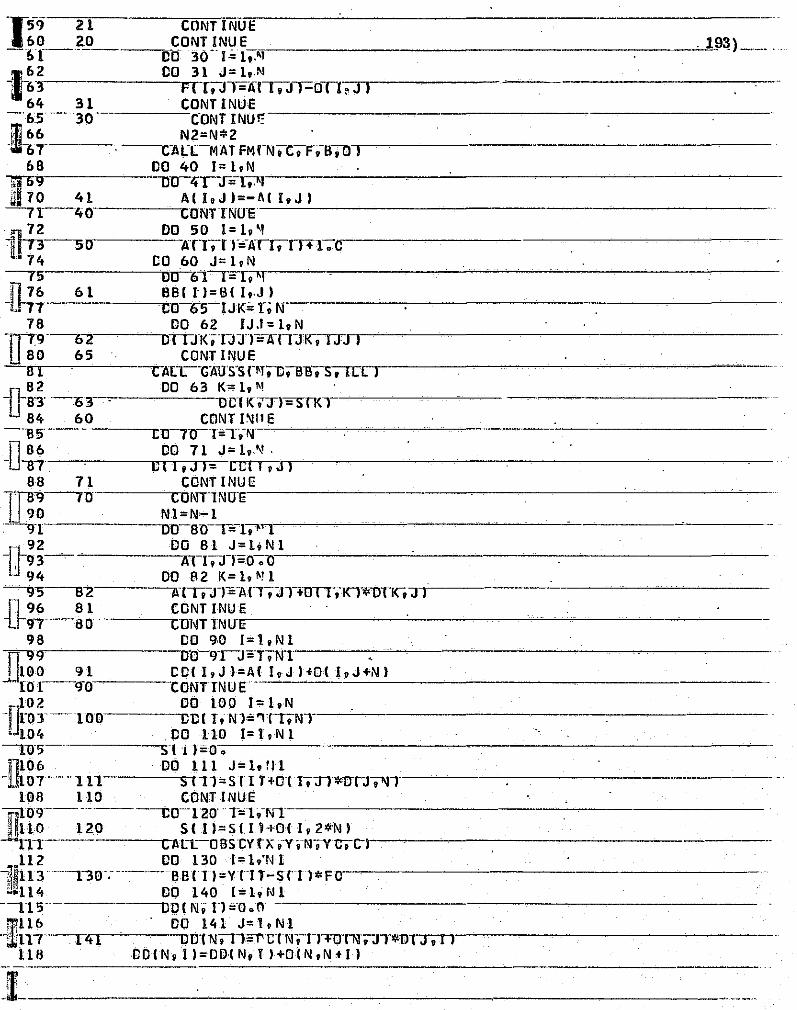
lr59 21 CONTINUE 160 20 CONTINUE -1.1---------"'00 30--r= I •. '!
, IP~)-.-. ,_. I .~
'-' J j
i-~-~ 00 F~8i!i~.rr-OTl-.--'-J'-I------64 31 CONTINUE
-65--- 30--- C-ONTINUI; ill 66 N2=N*2 -tlh 7- C-AI:CMAT FM'-N'C'F.-r.O'---'I'---~~--------------~---
68 DO 40 I=I,N 1iD~ DO qy-S=-~1'-----------~-~-----------~----~--------UI 70 41 A I I, J ) =-1\ I I, J ) ---n--ltO- CONnNU-e-----'----''--'----=-----'----'----------------~------------
~ DO SO 1=I,~, 11 ' $----SO ATT'lr"'-/WIfTT+l. c
u 74 CO 60 J= I,N --rS Ocr-6A~I~=~1~,u.'--~~~-~~~-----'----'~~~--~------------
_~776 61 BBII')=BII.,J) In ----------...CO-6S-lJK=r."Nr-~-~~-:------------------------
i j J
;J '1 ., , j '1 -. 'i 1 )
4 'I J )
i :',"1
i -j
I i . 1
1 co ;
~ 1 !
78 DO 62 IJ.I= I.N
lJ-.9------0""2 OrrJK;TJJ-l"-ATIJI<;-r;rJ ) 80 6S CONTINUE B 1 I:"ALL--m:(IJS-S PT9DtBll'S--.rCr"L T) ----------------~----~
82 DO 63 K=I,~ i]-8-3' --0 3 DOl KTn= SfKl --------~
84 60 CONT 1\111 E ---as' Clr70-T=-r.-N-----------------------------
lD-~_ DO 71 J= 1,,"1, 1 o.-~---~oTITI~.TJ~J= ctTT,Jn,r------------~--------------
88 71 CONT INUE
W:tJ---,u COliITTNU"E---------'---------------'~----~-
90 Nl=N-l :-'-9-[ --OO-8n--Fq.""1----------~-----~--'--~------------
-11-92 DO 81 J=l.Nl 11 93 AI r.n=o---;-or---------'-'---~----------------94 DO A2 K=l.~!l
~3----S-Z ATr.TI=-A r-.. -JTHrrT,-Kl"l)TK9Jl-'------'----------~--'---n 96 81 CaNT INU E i.h,---61)- C'ONT1NU-,,-E'-------------'-------'--------------
98 00 90 l=l,Nl fl119 00-9-rJ=-T9Nl---~~-----------;....----------
OHIO 91 CCI (,J I=A( I,J )fOI I,J+i\I1 ..J. [0[---9"0 CONTINU[;---'-----c---------------------
102 DO 100 1= I.N , -DroT-loo CDII.-Nl='1Tr.NT ~;.- iI 1.04 . CO 110 1= 1" v'N 1
--r05-- s I n=o. 11106 DO III J=l.rll
1.llor--Ul s IT1=srr T+O I r.;n*lrrJt"l1'-~----------------108 110 CONT INue
-ru09-------------c0--'120'--T=1.-NT --~---------------
i: n~ 10 12 0 _ S I I 1=_ S I I hO I 1. 2 *N_ I TT Clln-OBscnx.-v ;-I'r'VUOC-~1 ----~--------'----
,112 DO 130 I = liN 1 t -~II13--no-.------ BBII J=vru-srn*FO ----------------------~114 DO 140 [:il,Nl ~'"
;> --n S- -001 N, n ='-0.0 ----------------~llb ' DO 141 J=l,Nl
! ---';lilT7--r41 OOTN'Tl:J'lCTN,-n'"'F()'f'N",n-*u''T('J-.'T"j -r) ------------------116 COl N. 1 I = 0 01 N. t ) +0 IN. N tI ) -------------------

-_H-r40-----C-mIlTlNlJ E 20 CCIN,NI=OIN,NI
- 21---"- R=O'~'O----' 194)
122 DO 160 1=I'Nl - -Z'r-160' R='R+OIN'IHDIT'N J
24 R=R+OIN,2*N) "-125 ··--·-BBINI=VINI-R*FO ;1126' CALL GAU SS ( iii, CD "=-!!::..B.:..' ::..S.:..,.:.I L::..L::...:.' ___________ ~--------~dl27- .-. 00-T70 1= 1.'1'1 3
128 IFIABSISI Il-IJI.LE.0.OOI.0R.ABSISIII).LE.C.OOll GO TO 170 ~-Z9 n1D"EX=-I,' ..
.• 330 17C CONTINUE' -131--- - ---TFrA as ( S IN I':' FO---"-OTN.l'ITr;ce ~C-;-d cn- il'Jl):l------------. J32 LMN=LMNtl -~IH" -----. F (INDEx. EQ.n .AND-;-INO~EQ~ 1""1 -GQ--TO' 600'0 ·13 4 I F I NUN B;:R.:..:.~G:.:· T~.:..:I:..:)~.....::G:.:0:.......:T_=0.....::.5:::.C:::.0:::.0 _______ ......:... __ . ______ _
1:3 5 G"O"'TO 1n
01.36 6000 WRITEI6,21001 ""1.31""------ -'WRITEI6,5502r .
L38 WR IT E16, 20nO 11101 I, J I, J= 1.N . ..:..::2..:..'..:.. • ..:..I_=.::1..:...:..:N.:.' __ . ____________ _
Tr!~- 2600 W~61-~. I*r~;. ~~; . .:.,..:..._'_ . ...:I~_..:...... ____ _ -tltT -R""R"lTEl6""955tflTQ-. 142 WRIT E ( 6, 5 5011 I
1 ~4""3 --'5500' ---. FORI-fAT ( '-'-." *******-*****-************.*******-**-*****'*.", '-.', , I 1,144 WRIT E ( 6. 20 () 0 )( S ( 1 I 01 = 10 N I -145- 210o--FORMATI "lIT'-" -YHE--N-X2N' MATlnX-'-~ll
t., Jt46 5501 FORMAT!' '.·Flll.F(21 •••••• FI"N-1I.EINI. N=·,13.2X.'ARE', fi/'" '._L47 550""2 Fm~MAn'·-"·T******-***-***·*-"{**********-***-**-*-*************" r.; L48 2000 FORMATI' ·,6E=-15_·.::...5:....·.::..' ___________ _ ~; . l"Ct!~'-'5000----;;TU~~NTINUE ~'" -'h 1 'EN:D -------------------~-----~.
~'.
SUBROUT INF,'IATFMIN,C. F, B.D", D I MIiNS ION 0 I 10, 20 " C ( 10' • F ( 10. 101 ,C 2 ( 1 r., ,B 11 0 ,1 0'
-[5 f, -OlMENS ION-(j1 Hl,10',·C3rfO)------··-·--·---------r'~55 CO 20 K=l.N U56---2· ... 0--~::.. C2(K)=CIY)"
157 DO 23 IJK=l,N r""5"8"" On--Z-21(=r;1\l·..::.:..:.:.....-~---·~~---~----------
-,l~:- 22 CU~~,~~~~~~~ 161 CO 25 J=I,N
-[152--'2 5-----.:3n I" C'3 ( I1+-C-ZTJT*'FTJ ,n J161 24 CONflN:J 11 __ . ____ ----------"----------~
IT.7t D!J26-[=l,1'''-
0165 e21 Ll=C3(L) '_ 1'66- -aIIJK,LI"C"IU-r
1& 7 26 CONT IN:J E -::1.68'-23 ··----CONT INUI1------·----------.....:. i1n169 DO 30. 1= l,N U[7l) c-znl==O~· -. --------------------------
17 t CO 31 J= 1. N n. L7"2 -." ..... -.,-.---, 'C211 I=C2( I HClJl*B( J,lT-11173 31' CONTINUE
--- ---------,-
--17 f,-30 -'-'CONTINUE '--- -_ •. _--;r.,~75.· . DO 50 1=1,"
-,lHi76 C( 1. rq-:nl=O .... "·---------------------------~'177 DO 51 J=I.1Il /.
e-:- ,-.-.. '."~-.-- .. ---'.--.---WR
k , -... --_._---, .. _--- .. --------
.1
1 ;,~
~.;
:1
,i 1 j , j j
.J 1 j j I 1
'.~ j
·.1·
~~

f.·
:.··········· r .
r - -: '.-' I .-. .<:-- ~. '""'C' - -'''~~ -'or' ,,"""""~;< .. ?'"~-~~~_:.:_,() " , . .'_. -", ««f4A - iP,i.,.;:a .. J. C ., 41"; _.,J 4j v·a;: f ,;0= .z .. \ -',.I t .,,$iiPM\t1*-;;S J"1lI!I.
~~l'!.(:!~?r-:~-:£t:."'-::::~:!!."';:?,_~~_,.""' ... ~"'._J._,_"'O: .... ~"'5"'~~'e"..r,,=~_J, ____ ... w._ " «."d .. '". __ .~~_ .. _.~z: ...... _'"'-~~...,_ "._ ,. ". ,_. _,-",,, _.,,-, '!!"'~."'i:?;>;.~.,.-'!' 'j
I-fif 5'1 0 11 vI +llff';-Oll.I +N-' +CIJ I*BI J.I I
. 1~~- 50"-~tgP~6 I~~~='-;N ______________ .195)_
l 81 DO 42 J=l,N ~ 88'2
3--- orr.J1<,T+Nr,;-o-;-o'
CO 43 K=hlll -184 ---onJR,J·+Nl;OfTJK-.-:r+f\fr+orl.n<~K-'-"'BTK .. n -----------'(l85 43 CONT INUE -~8(, 42 CONT I NUE:------------------------
187 41 CONTINUE
].'.8 B --4-0 C"Ql\fTlIiIUE=--~---'-----------~----------" 89 DO b 11 = I, N 190·------. -DO-60 .. J=1.-IiI----------------~-------
d'H 60 QII,JI=OI T,N+J I -, l')2' --61-' ---COIllTlNUE--------------------------
~ 93 DO 70 1=2'N -r9~ 00 (r-J=l·~ .. ~N~--~--~~--------~----------rl95 71 OII,J+NI=OII,J+N __ '_+Q~I~I-.. -~l~,J~I---------_---- _~_ !J96' ---70-----COIiiT INue-
197 RErJRN _[98 ENC----'----------------~----
199 SUIiROUT'f\H=oIEfCYIX,Y,N,YO,CI ------~-~~~~-~-
-~g~.----------Di~-i~~~:~ XII0,101. YIIO I,ll 10l,CI 101
L;02 DO 10 K=I,N '-'203- - ----XI2.Xj.lT~fEXP I"".;. r~rF r~;]75-;;'*XC2'KFC4-;77!r. *x( l-~KI + 14.175 :*YO _[]g; x.!.4-~;-1.~~~~~~ 1-0. (:91-18 .125. I *x I l,K 1-1~~25. *x 12l!:'_ + 1 8.125. "'YO
206 DO 15 J=l,~
[ 08 15 CON~ [NU'" -:!07-- Z. ('K+n=-Z(I{+rr+lfrJ9K+TP'CTJ-'
- .09--TO----CONnNUE=---~·------------------
210 DO 20 K=l'W llz11 HK I=Y (J -=z n{+Tl L~12 20 CONTINUE
. --Z1'3 RETURN .. ~:........--~---------------.------
il21~.. END
215 SUBROUTINE GftUSSIN,A,B,X,ILLI
~22. 1l·76. '""tIMENS tON-ATN,-IIIT.BTNT.XT'II'.:;,~-----------~-~----ILl'=O
- 1 B fFTN"'Tr4,T;"4 219 1 IFIlIlldIl2,.'1,2
-nr-122222 °1' '---Z XTl'I'=BTTI/AlT,-n !J2 RETURN ~£~'---~lLL=l~---------------------------------------------
;.-
n223 RETURN ·L224 .. It NtESS1=1\I;';'1 ------'-----
225 CO 13 1= l,'lJLESS 1 -:;2.26· ··----·----ElG=IIBSI AI Inn
-U~i~-----~~Usr=-I+1:--------------I. .---------~.---
279 DO 6 J=IPLUS1,N -Uno-- ---"1 F I ABS III I J ,T I I-Bl G 1-6,6,5'-~~2 31 5 e I G= ABS I A I J, I I I
~. '--'232 ----L=J· ....... -. --.----.-----.--- -----
: ;".~.fj~~. 43- 6 CONT INU G r-..---~------------------~--l~",;;> rFTllTGTll,I, II . ~'235 7 ILL= 1
----~~---------------------------------~----------: T. __________ ~. _____ -_--_ -~~---.- ---~-..

-i~~'--8- I~n~~~:~'oll'9 196) -~38 ,.- 9----- CO· 10- J= 1,~r'~-------'-------------
139 T EMP= AI L.,J I - 'fiO ACr,JT=AlT'-J)
~1 10 ~(t.JI=TEMP -242---' T EMP=B I L r- ------------------..,.---------1::· --·------BI I J =T EMP-----=B:....:'-=L...:..I = B,~I.:.I.:.I --.......:.-.-----------------
2(.5 11 DC 13J=IPLUSl,N ~1t6 QIJ01=ATJ,TrrATl,l) ~e47 DO 12K =(PLUSl,N
-iIt8---12 Aeri t<T=AI J ,K r~QUOT*Alr;t<T 2~9 13 8IJI=BIJ1-QUOT*BI II
-~~~~---I~----~-~r! ~I N,N) 115.14.-[5------:--ZS-2 RETURN~-------------------------
_J.l 5543 _ .ly __ ' -I-XNI N 1): ~~"!.y AIi'J. N ) tI~ = -255 16 SUM=O.
r~~r'-- I~~(jn=J~~p~u~ 10 N -!.b'B~f SlJM=-SU'HA n ,-JT*xTJ>
2':'Q XIII=IBII)-SUMI/AII.11
1J~~- T~:~T~18"18:;~ ,~~-------'26218 - --- RETURN---
U63 END
$DATA -'----. - .. -._" --------------------- --- - --- - ---~ -- ._- --- .
,--------
-------------'------------------ ----------.---
-0-----------------rl ~J~~---~--~--------------------------------~----11- ------ -- --- ,----' --- --------
-[J ,
, .j
r i '