i - nasa · buckling of drill stem torque and power requirements appendix 2 appendix 3 appendix 4...
TRANSCRIPT

Geo Tech THE GEORGEW. WOODRUFFSCHOOL OF
MECHANICALENGINEERING
Georgia Institute of TechnologyAtlanta, Georgia 30332-0405
ME 4182
MECHANICAL DESIGN ENGINEERING
NASA/UNIVERSITY
ADVANCED DESIGN PROGRAM
t
/
LUNAR DRILL AND TEST APPARATUS
NOVEMBER 1988
David W. Norrington
Didier C. Ardoin
Stephen G. Alexander
Philip N. RowlandFrank N. Vastakis
Steven L. Linsey
An Equal Education and Employment Opportunity Institution A Unit of the University System of Georgia
https://ntrs.nasa.gov/search.jsp?R=19900014420 2018-08-03T11:48:03+00:00Z

///////////////// i

TABLE OF CONTENTS
ABSTRACT ....................... 1
PROBLEM STATEMENT .................. 2
BACKGROUND ON PDC TECHNOLOGY ............ 3
DESCRIPTION ................... 5
ANALYSIS ....................... 8
PDC CUTTERS .................. 8
STUDS ...................... 8
BIT/AUGER .................... 9
AUGER ...................... 10
BIT/AUGER WALL THICKNESS ............ 11
THERMOSYPHON ................. 11
THREADED CONNECTIONS ............ 12
FORCE, TORQUE, AND POWER REQUIREMENTS ...... 13
WEAR CONSIDERATIONS .............. 13
DRILL DRIVE MECHANISM .............. 14
ROTARY SPEED MEASUREMENT ........... 19
THRUST MEASUREMENT ............... 20
TORQUE MEASUREMENT .............. 22
PENETRATION RATE MEASUREMENT ......... 23
TEMPERATURE MEASUREMENT ............. 25
CONCLUSIONS AND RECOMMENDATIONS ........... 28
ACKNOWLEDGEMENTS ................... 31
REFERENCES ...................... 32

APPENDICES ...............
Appendix 1 Calculations
Appendix IA
Appendix 1B
Appendix IC
Appendix 1D
Appendix 1E
Appendix 1F
Appendix 1G
Appendix 1H
Appendix ii
....... 34
Spherical Roller Bearing Calculations
ScrewJack Bearing Calculations
ScrewJack Motor Calculations
Welded Bellows Calculations
Single Cutter Data Calculations
Cutter Stress Calculations
Bit Face Thickness Calculations
Buckling of Drill Stem
Torque and Power Requirements
Appendix 2
Appendix 3
Appendix 4
Appendix 5
Appendix 6
Appendix 7
Specifications of Drive Mechanism Parts
Radial Locations of Cutters and Stud Holes
Tolerances and Fits for Studs and Holes
Costs
Progress Reports
Figures

ABSTRACT
This report describes the design of an experimental lunar
drill and a facility to test the drill under simulated lunar
conditions. The drill utilizes a polycrystalline diamond compact
drag bit and an auger to mechanically remove cuttings from the
hole. The drill will be tested in a vacuum chamber and powered
through a vacuum seal by a drive mechanism located above the
chamber. The report consists of a general description of the
design followed by a detailed description and analysis of each
component. Because the design was not completed, the report does
not contain a step by step description of a test procedure. The
report does include recommendations for the further development
of the design.

PROBLEM STATEMENT
.,Background and Objectives
Drilling will be an important part of any future
exploration, colonization, or exploitation of the moon. Reliable
and effective lunar drilling technologies which may be operated
automatically must be developed. Our objective is to contribute
to the development of these technologies by designing a drill bit
capable of drilling a 51 mm diameter hole into lunar rock and of
transporting the cuttings to a chip basket for removal from the
hole. We will also design an apparatus to test the bit in a
simulated lunar atmosphere using pre-existing vacuum tanks.
Oonstralnts
The bit must drill rock in a hard vacuum at one sixth of
earth gravity without contaminating the walls of the hole or the
surrounding lunar environment. The deslgn should be s_mple,
reliable, predictable, and easily maintained since the bit will
ultimately be integrated into an automated system. A vacuum must
be maintained around the specimen during testing, and the test
apparatus must measure rpm, torque, penetration rate, b_t
temperature, and thrust on bit.

Background on PDC Technology
Polycrystalline diamond compact (FDC] cutters consist of a
polycrystalllne man-made diamond substance which is bonded onto a
tungsten carbide substrate. These cutters were developed by
General Electric and are marketed under the name Stratapax.
Typically, these cutters are bonded to a tungsten carbide stud
which is then pressed Into the drill blt.
PDC cutters drill rock by a process of crushing and fracture
initiation and propagation, and single cutter tests have shown
that penetration of rock occurs when the normal stresses between
cutter and rock exceed the compressive strength of the rock (1).
The mean penetrating stress is given by
= F/A w ,
where F is the vertical penetrating force, and Aw is the area of
the wearflat that actually contacts the rock (Figure 1.1).
Experiments wlth multiple cutters have shown that interaction
between cutters results in penetration at forces that are
significantly lower than those predicted by the above
equation (2).
Under certain drilling conditions, high temperatures may
develope at the wearflat. If hlgh enough, these temperatures can
lead to increased wear of the tungsten carbide backing, and
produce unfavorable thermal stress in the polycrystalllne diamond
layer. It has been shown that these effects produce thermally
accelerated wear at wearflat temperatures above 350 C (1). Thls
suggests that blt life can be improved If sufficient heat can be
3

removed from the cutters during the drilling process.
The literature suggests that bit llfe can be maximized by
designing the bit so that each cutter experiences equal cutter
wear (2). Design by this criterion is very difficult because the
wear depends on the actual depth of cut, speed, and interaction
with other cutters. However, this criterion can be approximated
by increasing cutter redundancy as radial distance from the bit
center increases (2).
4

DESCRIPTION
The lunar drill and test apparatus consists of a downhole
portion designed to drill lunar rock , a lunar slmulant, a drill
drive mechanism, and transducers and instrumentation to measure
pertinent dr1111ng data.
Downhole System
The downhole portion of thls design features a single piece
combination blt/auger made of hlgh strength steel which is
approximately i m long and Is 50 mm in diameter. The bit portion
utilizes polycrystalllne diamond compact (PDC) drag cutters
mounted on tungsten carbide studs which are pressed into the bit
body. The bit body has six channels cut In its outer diameter to
provide room for cuttings to move from the bit face to the foot
of the auger portion. The auger consists of three fllghts with
23 turns each at a rake of 15 degrees. The bottom half of the
interior of the blt/auger is sealed of and partlally filled with
mercury to create a gravity fed thermosyphon. The upper half of
the interior is used to simulate a removable chlp basket. The
purpose of thls Is to test the feaslbllity of collectlng cuttings
_n a downhole location for removal vla a wlrellne. Cuttings
wlll enter the chip basket through small holes cut in the walls
of the blt/auger near the top of the auger flights.
5

Lunar Simulant
We have chosen two types of rock for use as lunar slmulants.
These rocks, Dense Basalt and Hornblende Schist, are identified
in the literature on the subject as suitable lunar slmulants (3).
The basalt has a unlaxlal compressive strength of 16.4 kpsl and
the schist has a compressive strength of 20.2 kpsl. The rocks
will be cut into 2m x 2m x 2m blocks that will weigh 4,673 Ib
(Basalt) and 5,431 ib (Schist).
Drill Drlve Mechanism
The drive system for this application consists of several
major components. The first being the test platform which is a
support for all the other equipment. The drill stem passes
through this plate as well as through a drive platform located
above the test platform. The stem is encompassed in a
stretch-type vacuum seal. This seal is anchored to both the test
platform and the drive platform. It stretches as the drive
platform is raised or lowered. This movement is accomplished by
attaching the drive plate to the ball nuts of two ball bearing
screw Jacks. The screw shafts are rotated by a 1.5 horsepower
reversible motor. This drives the ball nuts, drive platform, and
drill stem up or down and provides the drilling thrust. On the
drive platform, a fluid rotary vacuum seal is used to enclose the
space between the stretch seal and the drill stem. Above the
drive platform is a motor platform. This supports the drive
motor and reducer for the drill stem. The entire drive apparatus
6

shall be enclosed in a steel housing to protect It from excessive
abuse.
Transducers and Instrumentatlon
The transducers and instrumentation are described in detail
in the analysis section.

ANALYSIS
PDC Cutters
The PDC cutters used on the bit are shown in Figure 1.2.
They are diffusion bonded to tungsten carbide studs which are
pressed into the blt body. The eight cutters are mounted with-
20 degrees back rake and -2 degrees side rake (Figure 1.1). The
back rake assures that the cutters remain in compression, and the
slde rake will impart an outward component to the velocity of the
cuttings, and thereby facilitate their removal from the hole (4}.
The radial locations of the cutters are shown in Figure 1.3 and
Appendix 3. The redundancy in the outer locations approximates
the equal cutter wear criterion and should increase the life of
the bit (2). The blt profile in Figure 1.3 shows a cross section
of the path that would be traced by the cutters if the bit were
rotated once without advancing. The bit profile is flat to
maximize the Interaction between cutters while holding the number
of cutters to eight. The Interaction between cutters should
assure that the actual penetrating forces required will be less
than those predicted by the single cutter model (Appendix 1E ).
Studs
The tungsten carbide studs are shown Figure 1.2. The hole
in the center will allow the working fluid of the thermosyphon to
come into close proximity to the cutter wearflats. The studs are
made of tungsten carbide - 3_ cobalt with a compressive strength
8

of 615 kpsi and a transverse rupture strength of 170 kpsi (5,6).
The stress calculations are shown in Appendix 1F. Because
tungsten carbide is a relatively brittle material with a hlgh
compressive strength, we assumed that failure would occur at the
point where the stud meets the bit and the tensile bending
stresses are maximum. Assuming a maximum thrust of 3000 ibf and
equal thrust per cutter gives a penetrating force of 375 ibf per
cutter. The literature on the subject indicates that it is
reasonable to assume that the drag forces will be equal to the
penetrating forces (2). We used a value of 3 as a conservative
estimate of the stress concentration factor and an outside
diameter of 8.2 mm, and we found that an inside diameter of 4 mm
results in a safety factor of 1.78.
Blt/Auger
The blt/auger is made from AISI 4140 steel normalized at
1600 F, quenched in o11 from 1500 F, and tempered at 1000 F. The
blt has slx cutting channels extending from the bit face to the
foot of the three flight auger. Each auger flight is fed by two
channels. The face of the bit is flat and is drilled to
accommodate the cutter studs (Figure 1.3).
The radial locations of the stud holes in the blt body are
shown in Figure 1.3 and Appendix 3. The holes for the outermost
cutter are drilled at an angle of 33.5 degrees from vertical in
the plane containing the central axis of the bit and the central
9

axis of the hole. This allows the outermost cutters to extend
0.5 mm beyond the outside diameter of the blt/auger (Appendix #).
Thls should reduce friction and wear of the blt/auger.
Tolerances and flts for the studs and holes are given In
Appendix 4. These provide an ANSI FN4 force fit (6).
The dimension labeled X in Figure 1.4 was chosen to provide
backing for the stud and to eliminate excessive deflection. We
ignored the support provided by the force fit and assumed that
the entire load Is carried by the material above the stud, and
that the mechanics can be modeled as a cantilevered beam under a
uniform load (Appendix 1G). Using these assumptions, we found
that X = 8 mm results in a maximum deflection of .00001 mm, which
is quite acceptable. Thls dimension is also sufficient to avoid
failure by shearlng(Appendlx IG).
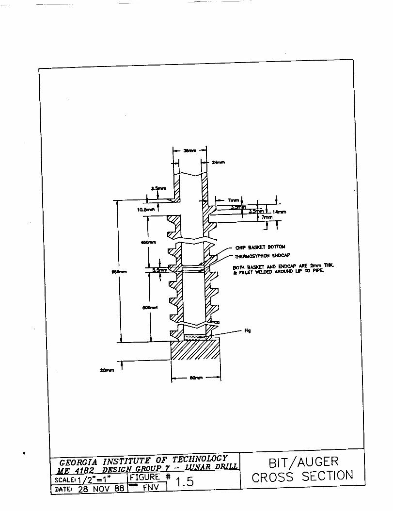
The auger flight geometry is shown in Figures 1.3 and 1.5.
The maximum volume of cuttings that can occupy the auger at any
one tlme is 5.95 x 105 mm 3 (Appendix #). Cuttings wlll travel up
the auger and fall into an internal chlp basket through
perforations in the blt/auger walls (Figure 1.5). If the bottom
of the chlp basket is located 450 mm below the perforations, the
chlp basket volume wlll be 2.04 x 105 mm 3, which is the volume of
cuttings generated by drilling approximately 100 mm of rock.
Thls should be sufficient to demonstrate whether of not cuttings
10

can be made to enter the chip basket.
Bit/Auger Wall Thickness
We chose to make the dimensions of the drill pipe the same
as those of the blt/auger walls, and we determined these
dimensions through buckling considerations. For simplicity, we
ignored the added stiffness due to the auger flights, and treated
the auger as if it behaved llke a pipe. In this way, the
analysis applies to both the auger and the plpe. The
calculations are shown _n Appendix 1H. With an unsupported
length of 4 ft, a maximum load of 3000 ibf, a factor of safety of
3, and an outside diameter of 36 mm, the required inside diameter
is 32.2 mm. However, this does not account for the perforations
In the auger walls that lead to the chip basket. To make up for
this, we chose an inside diameter of 24 mm. This resulted in a
safety factor of 6.8, ignoring the perforations. We feel that
this large safety factor and the fact that the auger flights will
add stlffness to the system should assure that the drill string
will not buckle at the perforations.
Thermosyphon
Wearflat temperatures greater than 350 C have been shown to
cause thermally accelerated wear of PDC cutters and studs (1).
Therefore some method must be found to remove heat from the
cutting surfaces. We propose that a thermosyphon be incorporated
into the blt/auger to accomplish this task (Figure 1.5). To
11

bring the working fluid into close proximity to the cutting
surfaces we have designed the tungsten carbide studs with 4 mm
holes along the center lines which extend 16 mm into the studs
(Figure 1.2). These holes will match up wlth similar holes
drilled into the blt/auger interior creating a passage for the
working fluid. We think that mercury might work as a working
fluid, but much analysis is needed to determine the feasibility
of this proposal. Potential problems include the possibility of
forming vapor pockets inside the studs, compatibility of the
mercury with the blt/auger and stud materials, and the transfer
of heat from the condenser end of the thermosyphon to the
environment (7).
Threaded connections
We propose that threaded drill pipe connections be used to
connect the bit auger, the drill pipe, and the drive shaft. We
suggest American Petroleum Institute (API) Rotary Shoulder
Connection dimensions. We recommend a V. 0.055 thread form with
a 12.5 % taper and a 3.7 mm thread height. This thread will have
6 threads per inch and a pitch of 0.167. This connection must be
cut into our existing drill pipe which has an outer diameter of
36 mm and an inner diameter of 24 mm. This connection will give
us a thread engagement length of approximately 30 mm which we
believe is appropriate.
We have not done a stress analysis or a detailed design on
this specification and suggest that this be done before the
12

project proceeds any further. It is possible that the OD of the
bit auger and the drill pipe may have to be increased in the
vicinity of the Joint to maintain the load bearing capabilities
of the drill string.
Force, T.orque, and Power Requirements
Appendix II shows the torque and power requirement for the
test apparatus based on a maximum thrust of 3000 ibf and a
maximum rotary speed of 200 rpm. In the calculations, we have
assumed an equal d_strlbutlon of the load and a coefficient of
drag equal to 1.0 (2). The calculations show that the test
apparatus must be capable of transmitting at least 1825 lbf-in of
torque to overcome the cutter drag forces. However, extra torque
will be required to overcome friction between the auger and the
walls of the hole. We were unable to predict the magnitude of
this extra torque, so we doubled our torque requirements in the
hope that the actual torque will be less than this design torque.
This gives a torque requirement of 3680 lbf-in. At a maximum
speed of 200 rpm, the test apparatus must deliver 11.58
horsepower.
Wear Conslderatlons
Frictional wear of the outside diameter of the blt/auger
will be a major problem with this design. Thin coatings of
titanium nitrlde (TIN) have been shown to enhance the friction
and wear characteristics of cutting tools. In some applications,
13

wear rates can be decreased by a factor of 10 (8). To reduce the
wear rate and frictional forces, we propose to coat the blt/auger
with a .003 mm layer of TiN using a physical vapor deposition
(PVD) process known as sputter ion plating. PVD methods are
preferable to chemical vapor deposition (CVD) methods because the
are carried out at temperatures well below the normalization
temperature of most steels. This eliminates the need to repeat
the heat treatment and eliminates thermal distortions which can
occur with the high temperature CVD methods (9}.
Drill Drive Mechanism
The overall purpose of this portion of the apparatus is to
provide both rotary and linear motion to the drill stem. In
approaching this task, several options were investlgated and
numerous difficulties were encountered.
After extensive research and discussion the followlng design
was agreed upon (Figure 3.1). It was decided that the drive will
be mounted outside the vacuum tank with the drill stem enterlng
through the 8 inch flange at the top of the tank (Figure 3.2). A
14' by 10' by 2" steel plate (Figure 3. 3) will be mounted on the
flange via 14 1" - 8 threads per inch bolts on a 25" bolt circle
and an 8" inner diameter, 32" outer diameter vacuum gasket. This
will serve as a test platform to support the drive system. There
will be two arch supports between the plate and the tank (Figure
3.4). These will help prevent any undue deformation of the
plate.
14

At the flange, a problem was encountered when we attempted
to find a method of maintaining a hard vacuum on the inside of
the tank and atmospheric pressure outside. In addition, the pipe
entering the flange must be allowed to both rotate and move
linearly in and out of the tank. Various vacuum seal
manufacturers were contacted in the search for a solution to this
problem. Many vacuum seals were available that would allow pure
rotary motion and even one that would allow pure linear motion
but no seals were available for a combination of these actions.
After some consideration, it was decided that an outer pipe
should be used to encompass the inner I 11/18" diameter drill
stem pipe. In this approach, a rotary vacuum seal could be
anchored to the non-rotatlng outer pipe. The vacuum seal chosen
for this application is a fluld-type wlth a stainless steel
housing (Figure 3.5). It has a maximum speed rating of 2870 RPM,
a torque capacity of 12,445 in-lb and a thrust load capacity of
5200 lb. This fluid seal will be mounted directly above the
drive platform (Figure 3.1) using 6 - I0 - 32 UNF on a 6.0 inch
bolt circle and an o-rlng. As this seal is capable of supporting
a thrust load, it can also act as a thrust bearing. This type of
fluid seal requires a small pump for the fluid and has tube
fittings for use with tubing In llne with the 4 face mounting
holes. Although this pump has not been located, they are
commercially available from various suppliers as well as the
vacuum seal manufacturer. The linear motion vacuum seal for the
outer pipe to the flange is somewhat more complex. It basically
15

consists of a set of stacked washers welded so that the washers
can stretch or compress. This apparatus is known as a welded
bellows. It has a 8:3 maximum extended length to maximum
compressed length ratio. Therefore, in order to achieve a
maximum travel of 8 feet (approx. 2 meters), a welded bellows of
12.8 feet maximum extended length and 4.8 feet maximum compressed
length is required. The bellows will have an inner diameter of 2
inches and an outer diameter of 3.5 inches. The lower end of the
bellows will mount to the test platform via a 32" flange, 25"
bolt circle, and 14 - i" - 8 UNF bolts and an o-ring to seal that
connection. This flange will match directly with the flange on
the vacuum tank and will use the same bolts. The upper flange of
the bellows will mount directly to the drive platform (Figure
3.6), making the actual outer pipe unnecessary. This mounting
will use 6 - 10- 32 UNF bolts on a 6.0 inch bolt circle and
another o-rlng seal. This mates to the drill stem, and allows
both linear and rotary motion in the stem.
The previously mentioned drive platform is made of 4' by 8'
by I" thick hot rolled steel and it is mounted to two
ball-bearlng screw Jacks. To facilitate this mounting, the drive
platform has two 2.75 inch holes spaced 89.25 inches apart center
to center (Figure 3.7). In addition to these holes, there is a 2
inch bore in the center of the plate to allow the drill stem to
pass through. The drive platform will be mounted to the screw
Jack nuts using 4 - .25" bolts on a 3.25 inch bolt circle. In
this way, as the screw Jack nuts are raised and lowered, the
16

platform and drill stem are raised and lowered.
The installation of the ball bearing screw Jacks is
necessary in order to create the required thrust. For this
application there is a need for 3000 ib of downward thrust. The
ball-bearlng screw Jacks chosen have a 2.5 inch nominal diameter
screw with a 0.25 inch lead. These screw Jacks are capable of a
thrust load in excess of 5000 lb. The screws are placed in
tension to reduce stress on the screw and minimize vibration. By
doing this, the screws can be utilized at higher speeds than
would be normally possible. The screw shaft should be machined
down to a 2.25 in outside diameter rather than increased to avoid
any unnecessary stress concentration. To maintain the tension in
the screws, 4 - 2.25" diameter spherical roller bearings, one
mounted at each end of each screw, will be used. These bearings
will use flange block mountings and will be attached to the test
platform and to the Jack anchor supports (FiD_ire 3.8). The
bearings selected have the required 0.75" inner diameter, and are
capable of 6000 Ibs of tension assuming a radial load of 4700
lbs. This should yield a life of 1000 hours assuming the most
stressful conditions. The bottom set of bearings shall be
mounted directly to the test platform, over the 2.?5 inch bores
for the screws, using flange blocks. The upper set shall mount,
using flange blocks, on top of Jack anchor plates (Figure 3.1).
These plates are to be attached to the enclosure wall and each
will have 4 8 by 8 I-beam supports welded between the anchor
plates and to the test platform. This will ensure increased
17
rigidity in the structure. A 1.5 horsepower variable-speed,
reversible gear motor is to be mounted on the test platform In
between the two screw Jacks. This motor (Figures 3.1 and 3.I0)
wlll drive the two screws using sprockets and 2 high torque drive
(HTD) belts. In thls way, the level of the drive platform and
drill stem may be adjusted, in addition to applying thrust to the
drill stem and bit.
Two other thrust bearings are to be used, in similar
conditions, to support the weight of the drill stem. These
bearings will be mounted in special brackets Just above the drive
platform (Figures 3.1 and 3.9). These bearings have a 1 11/16
inch inner diameter, and will be capable of withstanding a thrust
load of 3000 Ibs and a radial load of 1300 Ibs. These figures
produce a design llfe of 1000 hours. (Mathematical analysis of
all bearings may be found In the appendix). The brackets to
anchor these bearings will be manufactured so that flange blocks
may be attached without interfering with the drill stem motion.
Another platform, the motor platform (Figure 3.11), shall be
located above the drive platform (Figure 3.1) to allow placement
of the motor and reducer, known henceforth as the gearmotor.
This gearmotor consists of a 15 horsepower NEMA "C" face motor
and a 5:1 single worm reducer. Thls reducer is mounted on a 500
RHC gearframe. The reducer is a rlng-base type wlth a hollow
shaft output. (See appendix). The drill stem shall become a
double keyway shaft above the motor platform. These "keys"
should directly oppose each other along the diameter of the
18

shaft.
It is recommended that the entire apparatus be enclosed in
i0 gauge hot rolled steel. This structure should be 17 feet high
to allow for ample movement of the motor and drive platforms and
the drill stem. The roof should measure 12 feet in length by 8
feet in width. This enclosure will not only increase the overall
rigidity of the structure but it will also keep the equipment and
area safe from dust, debris, and the weather. Also the structure
should have an 3.5 foot by 8 foot door on one of the smaller
walls of the enclosure to facilitate easier access for
maintenance during testing and an air circulator should be
installed to remove excess heat from the area during operation.
Finally, it is suggested that a remote control panel (see
appendix) be located in an existing building convenient to the
vacuum tank site. This control panel would allow the operator to
adjust speed, thrust and drill height as well as display
approximate instantaneous values. This building will also be the
location for the instrumentation controls.
Rotary Speed Measurement
The revolutions per minute of the drill shaft will be measured by
a microprocessor tachometer/process time indicator manufactured
by Kernco Instruments, Inc. (Model number 1735, Catalog number
21C15) .The input sensor used will also be from Kernco
Instruments, Inc. (Catalog number 995-SMC). The 21C15 displays
units of rate : RPM, MPH, IPS. The 21C15 also displays units of
19

time per event for process time functions. A built-in memory
provides recall of minimum, maximum, and average measurements
selectable through a front-panel switch. The RPM range for the
995-SXC photoelectric sensor is 1-1,000. The photoelectric
sensor will be mounted on a 1.25 foot stand on the drive platform
and under the motor platform. The sensor will be two feet from
the front of the drill stem and directly under the motor. A
reflective mark will be placed on the drill stem 1.5 feet above
the drive platform. The reflective material is provided by
Kernco when the photoelectric sensor is purchased. This
reflective mark wlll be the indicator for the photoelectric
sensor. A cable will connect the sensor to the microprocessor
which will display the measured RPM. The microprocessor will be
located in a small booth housing all instrumentations outside of
the test facility.
Specifications
Display
Accuracy
Power
Size
Weight
: 5 digits (0.5" LED)
: 0.01_
: 120 VAC 50/60 Hz
: 5.6" X 2.8" 6.2" depth
: 2 ibs. 7oz.
Thrust Measurement
The force being produced by the drill stem on the lunar
slmulant will be measured by hollow load cells manufactured by
2O

Eaton Corp. A load cell will be placed against each set of
bearings on the drive platform above the rotary seal pump. The
total force exerted will be the sum of the forces produced on
each load cell. The inner d_ameter of each load cell was
specified to be 1 3/4".
Specifications for Model 3336 Load Cell
Nominal Load Limit Capacity : 5000 ibs. or 20000 newtons.
Static Overload Capacity : 150_
Sheer Load Limit :
Bending Load Limit :
Torque Load Limit :
550 ibs.
12000 in-lbs.
1850 in-lbs.
Load Limit Deflection : 0.005 in.
Output at Rated Capacity (mV per V, nominal) :
Nonlinearity (of rated output) : ± 0.25_
Hysteresis (of rated output) : ± 0.15%
Repeatabil_ty (of rated output} : _ 0.15_
Zero Balance (of rated output} : ± 1.0_
Bridge Reslstance (ohms nominal) : 350
Temp. Range, compensated (F) : + 70 to + 170
Temp. Range, compensated [C) : + 21 to + 77
Temp. Range, usable (F) : - 65 to + 200
Temp. Range, usable (C) : - 18 to + 93
Temp. Effect on Output (reading per F) :
Temp. Effect on Output (reading per C) :
Temp. Effect on Zero (reading per F) :
+ 2
+ 0.002_p
+ 0.0036_
+ O. 002_
21

Temp. Effect on Zero (reading per C) : ± 0.0036%
Excitation Voltage, Maximum (volts DC or AC rms) :
Insulation Resistance (megaohms @ 50 VDC) : >5000
Number of Bridges : 1
20
The display instrumentation for the force will be a Tedea,
Inc. Model AD4321. The two load cells will each have cables
connecting them to the digital display in the instrumentation
booth.
Specifications for the Tedea, Inc. Model AD4321
-Resolution to 1 part in 1000
-Drives up to 4 x 350 ohm load cells
-115/230 VAC or 12 VDC power
-Serial RS-232 output
-Rated output : 2mV/V
-Safe overload : 150% rated output
-Excitation : 10-20 VAC or DC
Torque Measurement
The torque transmitted by the gearmotor to the drill stem
wlll be measured by a torque meter manufactured by the Technical
Data Division of General Thermodynamics (Model E). The "E" type
torque meter is designed to couple between a drive and a driven
22

member, operate in any position and sense torque in either
direction of rotation. The system consists of two parts, the
torque sensor and the meter readout.The sensor will be directly
connected to the motor and the output shaft.The model number E-
80B-IKPF was chosen based on the upper torque range of I000 ib-
ft.
Specifications
Accuracy : Torque readings are accurate within 0.2% over entire
range.
Dual Range : The lower 1/4 and 1/10 of the range may be expanded
to read full scale.
Transducer Callbratlon : Within I/2% of full scale.
Material : Aluminum body, steel shaft, ball bearings with packed
grease.
Loading : Inllne, transmitted torque.
Maximum Safe Load : Twice full scale rating.
Penetration Rate Measurement
The penetration rate of the bit will be obtained by
indirectly measuring the distance the bit has moved and sending
%hls information to a count-tlme-rate display controller.
The distance and rate will be measured in the following way :
I • A 2.25 in diameter, i/8" thick disk will be mounted
from the motor-side Jack anchor plate in direct
23

rolling contact with the solid shaft tip of the screw
Jack. This disk will have 16 0.25 in slots cut at
regular intervals on the outer diameter of the disk.
.
.
•
An op%o isolator wlll be mounted on the anchor Jack so
that the disk will extend 3/8" inside the LED of the
device.
Each time a slot is passed through the LED, a pulse is
sent to the count-tlme-rate controller at which time
the display is updated.
For each complete revolution of the screwJack, the bit
will travel 1/4". For each pulse sent to the
controller, the bit will have traveled (1/4")/ 16 =
1/64" = 0.015625".
The opto isolator will consist of an ECG 3101 LED-Photodlode
and a 1" diameter, 1/8" thick disk with specified slots. The
LED-Photodlode will transmit a pulse to the controller each time
a slot passes the photodlode. The disk will be made of
plexlglass painted Jet-black to prevent light transmission
through the disk. The count-time-rate controller is produced by
Kessler-Products, Co. (Model Keptrol)
The unit wall display count, time, or rate. The time base can be
set for sec., mln., or hours. A conversion chart will accompany
the controller with the following conversions :
24

RATE (pulse/time)
r =
r =
r =
r =
r =
r =
RATE (unlts/time)
r (in/sec)
r x 60 (in/mln)
r x 3600 (in/hr)
r X 2.54 (cm/sec)
r x 152.4 (cm/mln)
r x 9144 (cm/hr)
Specifications For Controller
Accuracy :
Display :
100% (100 kHz count speed, .015_
accurate crystal based timer)
0.0001 - 99.9999 scaling factor 8 digit
alphanumeric display, 0.55 in LED
Operating Power Source: 110 or 220 VAC. or 12 to 27 VDC
Preset outputs :
Preset functions :
Panel Housing :
Dual, two 10-Amp relays
Alternate action, latching, or momentary
output from 0.1 sec To 9.9 sec
7.37 in by 2.5 in, 6.00 in deep
Temperature Measurement
The task of measuring the bit temperature created many
problems due to the design of the blt and drive system. Below is
a llst of possible ways to measure bit temperature and why they
25

were not applicable in this situation.
Thermocouples--While thermocouples imbedded in the bit provide a
very inexpensive, simplistic way of measuring the bit
temperature, they are unable to be used due to the fact that they
must have wires running from them to the display panel. There is
no possible way to accommodate this in the bit design due to the
partial solid shaft and heat pipe restrictions. Another problem
presented by thermocouple wiring is that the wires would
constantly be twisted by the rotating bit and eventually break.
Optical Temperature Transducers--The optical temperature
transducer would be ideal for thi_ application if a llne of sight
were obtainable to the bit tip. This, however, is impossible due
to previously mentioned restrictions.
Slmulant Imbedded Thermlstors--Thermlstors would not be practical
to plant in the lunar slmulant due to the fact that they could
change the drilling conditions or alter the environment, thereby
affecting the outcome of the test results.
Temperature Strlp--Thls strip, made up of reactive substances
which change color at different temperatures, would also
encounter the problem of having no llne of sight. It would also
be very difficult to obtain these reactive substances which could
withstand the friction and wear forces produced by the bit and
26

the lunar simulant.
Radlo-transmitted Slgnals--The noise generated by the motor,
drilling procedure and vibrations would make a radio signal very
difficult to be transmitted accurately to a receiver. Another
problem with the radio signal is the transmission of the signal
through the bit and the durability of the transmitter.
27

CONCLUSIONS & RECOMMENDATIONS
Although we did not fulfill all of our obJectlves--
our design is not yet ready for fabrication and testing -- we
feel that we have come a long way toward reaching our goal of
developing effective lunar drilling technology. However, there
is much work left to be done, and we feel that our work should be
viewed as a point of departure for the further development of
this technology rather than as a completed design.
Bit/Au2er
We feel that PDC drag bit technology may be used to drill
lunar rock if we can find a way to effectively deal with the
frictional heating of the cutting surfaces. We recommend that a
detailed analysis be carried out on the use of a thermosyphon or
heat pipe to remove heat from the cutters. Also, we feel that
our auger will remove the cuttings from the hole if the formation
is only moderately hard and the cutting dimensions are on the
order of 0.5 mm. However, the fine cuttings generated when very
hard rock is drilled may be difficult or impossible to move with
a conventional auger. We recommend that the present auger be
abandoned in favor of a stepped auger system which would be
operated by linear reciprocating motion. This would require some
method of moving cuttings from the bl% face to the foot of the
stepped auger.
28

We have not completed the design and analysis of the
threaded drill string connections. Of course, any further
development of this design project should include a detailed
design of the connections including consideration of non-threaded
connections.
The complex geometry and loading conditions of the bit�auger
and the carbide studs required us to limit our analysis to highly
simplified models which may be inappropriate. We recommend that
finite element techniques be employed to obtain a stress analysis
of the blt/auger, the studs, and the cutters.
Finally, tolerances and manufacturing techniques have not
been specified. Obviously, before any of this design can be
built, the tolerances and methods of manufacture must be
specified.
Drill Drive Mechanism
There are several areas of the drill drive mechanism which
need additional attention. A small pump is needed for the fluid
vacuum seal. This pump should be mounted an either the motor
platform or the drive platform with tubing leading to the four
tube fittings of the seal. This will ensure a complete seal
around the drill shaft.
Another area for improvement is the overall steel structure
( platforms, I-beams, and channels). These members have been
29

designed for large factors of safety, yet attention must be
directed toward the welds and bolts used to attach these pieces.
These components should be analyzed for stress and fracture, and
their dimensions should be verified.
It is recommended that a 10 gage steel enclosure be
constructed around the entire drive apparatus. Although
dimensions have been speclfled, the structure is still in the
preliminary design stage and needs much attention in the areas of
welds, fasteners, and stress analysis. Also, a remote control
panel should be located in an observation booth. The panel
should have controls for both gearmotors, the fluid vacuum seal
pump, and _nstrumentatlon to display pertinent drill_ng data.
3O

ACKNOWLEDGEMENTS
The Lunar Drilling Apparatus Design Group would like to
acknowledge the followlng people for their assistance in
designing or selecting equipment for this project.
I) Khawan Amwar, A111ed Devices Corp.,
Drawer E, Bladwin, N.Y. 11510, (516)-223-9100
2) Art Fisher, Standard Steel Specialty Co.,
P.O. Box 20, Beaver Falls, Pa. 15010, (412)-846-7600
3) Richard Goldy, Thomson Saginaw Ball Screw Co., Inc.,
P.O. Box 9550, Saginaw, Michigan 48608,
(517)-776-4123
4) James G. Hartley, School of Mechanical Engineering,
Georgia Institute of Technology
5) Anthony Koyenskl, Jr. Key High Vacuum Products, Inc.,
36 Southern Blvd., Nescanset, N.Y. 11767,
(516)-360-3970
6) Curtis Wright, Duff Norton, P.O. Box 32605, Charlotte,
N.C. 28232, (704)-588-0300
7) A. V. Larson, School of Mechanical Engineering, Georgia
Institute of technology.
31

REFERENCES
•
•
•
,
•
,
•
,
•
10.
11.
Glowka, D.A., Deslqn Considerations for a Hard-Rock PDC
Drill Bit, Sandla National Laboratories, Geothermal
Technology Development Division 6241, 1985
Glowka, D.A., Implications of Thermal Wear Phenomena for PDC
Bit Design and Operation, Sandia National Laboratories,
Geothermal Technology Development Division 6241, 1985
Westinghouse Electric Corporation, Summary of Moderate Depth
Lunar Drill Development Program From Its Conception to 1
July 1972, Final Report, 3un 1972
Maurer, W.C., Advanced Drilling Techniques, Chp. 22, pp.
587-589, Tulsa, Oklahoma, The Petroleum Publishing Company,
1980
Bornemann, A. et al., Slntered Carbide for Cuttlnq Tools,
Metals Handbook, 8th Ed., Vol. 3, 1967, pp. 316-322
Avallone, E.A. and Baumelste, T. III, Marks' Standard
Handbook for Mechanical Engineers, 9th Ed., New York,
McGraw-Hill Book Company
Dunn, P.D. and Reay, D.A., Heat Pipes, ist Ed., New York,
Pergamon Press
Jacobs, M.H. , Process and Engineering Benefits of
Sputter-Iron-Plated Titanium Nitrlde Coatings, Surface and
Coatings Technology, November 1986, Vol. 29, No. 3, pp.
221-297
Sollenberger, N.W., Performance and Evaluation of Titanium
Nitrlde Coatings, Thesis, Georgia Institute of Technology,
September, 1978
McGregor, K., The Drilling of Rock, CR Books Ltd, London,
1967.
McNalr, Wlll L.,The Electric Drilling Rig Handbook,
Petroleum Publishing Co., Tulsa, Oklahoma, 1980.
32

Product Catalogs (consulted but not cited in text)
Bearing Technical Journal, FMC Corporation, Link-Belt Be ar i ng
Division, Indianapolis, Indiana, 1970.
Boston Gear, Boston Gear Incom International Inc., Quincy,
Massachusetts, 1985.
Browning Power Transmission Equipment, Browning Manufacturing
Division, Maysville, Kentucky, 1986.
Electra Motors, Dresser Industries, Inc., Anaheim, California,
1985.
Georgia Steel Supply Company, Atlanta, Ga. 1987.
Industrial Power Transmission Products, T.B. Wood's Sons Company,
Chambersburg, Pennsylvania, 1985.
Link-Belt and Stearns Power Transmission Products, PTC
Components, Inc., Indianapolis, Indiana, 1984.
33

APPENDICES
34

ADDendlx IA
Spherical Roller Bearing Calculatlon_
For Drill Stem :
diameter = 1 11/16 in.
assume Fama x
Frmax
nmax
(thrust load) = 3000 Ib
(radial load) = 1300 ib
= 300 RPM
1) (c/P) = ((L n 60)/(1000000)) °'3
--for bearings wlth shaft diameter > i in.
where :
C = basic load rating
LIO = rating llfe
n = speed
P = equivalent radial load
P = 0.67(Fr) + 2.25(Fa) if
P = 0.67(1300) + 2.25(3000)
P = 7563.03 ib
(Fa/Fr) > 0.45
(Fa/Fr) = 2.3077
(C/P)(P) = C, C = 18000 ib for bearings with 1 11/16 inner
diameter.
-- 1800/7563.03 = (C/P) , (C/P) = 2.38
2) LIO = ((C/p)lO/3(lOOOOOO)/(h 60))
LIO = ((2.38)10/3(1000000)/(300
acceptable.
60) = 1000 hrs, which is

A_endtx 1B
Calculatlons for Screw Jack Bearings
Shaft Diameter
Desired LIO mln
nmax
= 2.25 in.
= 1000 hrs
= 40 RPM
(c/e) = ((lOOO x 40 x 6o)/(1,ooo,ooo)) o.3
(C/P) = 1.3, C = 23600 lb
(C/P)(P) = C, P = 23600/1.3 = 18153.85
P = 0.67(Fr) + 2.5(Fa) = 18153.85
--iteration yields
Fama x = 6000 ib
Frma x = 4700 ib

Appendix IC
Ball Bearing Screw Jack Motor Calculations
To find the torque necessary to convert rotary motion to
llnear motion :
T = 0.177(P)(L), where P = load, and L = lead in inches
T = 0.177(1500)(0.25) = 66 in-lbs --for each screw jack
With a 0.25" lead, 4 revolutions will yield 1" of linear
thread. Therefore, if a maximum penetration rate of 80
in/min is assumed, a speed of 320 RPM would be required.
Thus :
Required HP = (n(2T)/(63000) = ((320)(2.66)/(63000)
Required Hp = 0.67 HP
A 1.5 HP gearmotor will be used to insure a greater factor
of safety and in the event greater thrusts are required.

Appendix ID
Welded Bellows Calculations
Required travel = 8 ft. (approx. 2 meters)
8:3 ratio of maximum extended length to maximum compressed
length.
a = 8 + b
b = (3/8)a
a = 8 + (3/8)a
a = 64/5 = 12.8 ft.
b = (3/8) (12.8) = 4.8 ft
Washers need approximately 1.5 inches difference in outer
and inner diameter to obtain maximum flexibility
Since :
drill stem
Choose bellows
from this bellows
OD = 1 11/16 in.
ID = 2 in.
OD = 3.5 In.

S _NGk.E - (% U'_TER DATA
V
AwJ ROCK
Aw WEAR - FLAT AREA
CC)MPRF_SS)VF_. STRENGTH OF ROCK.
SINC_LE - CUTTER TNRF_..51-_OLD FO,II_C..F_.
TOTAL "THRESHOLD ,Im"ORCE
FOR MC)DF_-..RA'I-F_... W'F__AR (Aw -- .Oi_ in._)>
I_ENETRATION t_EGIW,5 WHEN
F = ccA,,,,.
E_EC ALI.5 I_" WE HAVE
F-r - 8F.
8 CL.I-I-'r-F_..R_, i
DENSE.
BASALT
HORNE.. BLgN_E
5C.H ISTP_0.2
F (Ibm.) F-,-(.Ib¢.)
404. 3_3_

AEP_EhDJZ .t£CUTTER ._1 _S S
rl
A-_
' I I I
375 I1_.
_t A
0 =- 7"xy = q-yx (FRE.F_ Su R_AC, E-)
G'Y - fr_c + (-3751b_")]KTA
I"1 = (:57511::_.)(2_4 " in.)= 116.1 Ibm.-in.
C = r'z = 4-.i nnrn =- O. IGI4 ;n.
r, = _ m m = 0.07874 in.
KT = STRESS CONC. "- _%
A = 7r(r_- r,') =
(5.0a8)(Io) "4 in _
.o_23&, ir_.2
= r(,_S.l Ib.-in.)(.l_14in.)0_ L (5.0a8)(IO) -4 in. 4375 Ibm. _3
= q5,(,,q4 ps;
5u"r_, 170 _ ps ; = 1.78

B _T FACE
-- DE.FLE..C...T'I O N-
TREAT LIKE CANT.
I
H IC.K NF-.SST
jB II"--BODY -
(_4o) / | " j.
(we).' _,: :_
BE-AM t t9. " 2.1 mm 375 Ibm-.
b = 27r (5.05m_,) Ix= 8ram I
CO -- UNIFOt_I"I LOAD = i"_1:17&57 B--;
_ 17. (.D5 mrn 4
Y"× = 6F-.I =ram)4( 178.57 ram)(2.1
(8XaoXIofpsi H in. _ '_ (617. _5 ,-,-,,-,-t)_5.4.,mJ
ymAx= .OOOOI Irnm _ OK
-- PAILURE. BY SHEAR --
A : (6mm)(2"rr)(&os,'n,-,,) : 153.3,-_,-# : 0.2_7_ ;nfSsy = Su.,.s/2. = 135kpsi/:_ : G7,5OOps;
,T_u_x = (3V) [ 3 (375 IhE.)] = 23_7.4 psi2 A = 2 (o £37_ in.e)
f.S. = "_e'iY = 28.5
,'7-, I'_A'x'

I_UC.I_LINC_ ('_!: }-]RILL _%M
EUl..F_.P,'_ EQN. _s P_ =n_ 2 EI
w here
_ _--
E=
:Z=r--
P=
#.S,=
_=
_blD C.OND. COF_FFICIF--NT =
YOL_NC_'S MODULU__ = _%0 (JO) _ psiL_ING_rH = 48 in.MOmeNT OF ,N_T,A = _C r_- r,_)/4I_IPF_ RADIUS (rout -- 18 ram)
MAX I_OAD = 3,000 Ibm.SAFF--'I-_F FACTOR (TRY 3)
CRITICAL l-OAO : P(_,S.)= q,OOO Ibs.
.(_r)(q,_ Ibs.)(4_ im'32 : [(_--_.@ in.)_W 3 (_0)(IO) _ p_,
m,.: 0.#o354 in. : I_.1 rnm
._NALYSIS DOF--_ NOT ACP-.,OblNT FOP, HOLF-.S IN
PIPF--p @ USE. I"_w : IP_mm
,n-:'(BoX IO,)¢°psi _4/L_B.4
(48 i,,.) 2
PeR : P-O, 4-27 Ibs. : _.s. (3,000 Ibs.)
#.s.: _.8

AEEENDJ/ LT
ToR6_UE, AND POWER REQUJR_M_N'rs
T; = TORQUE. CF_F_A'I-ED BY CU'l"rER ;
r'i ; RADIAl- LOCATION OF CUTTER i
F" = THRUST PF_.R CUTTER--375 Ib£.
_qj = DRAG CO_i_ICI_I,J-/- = t
Fa = DRAG FORCE P_R CUTTER : Y"eF = 3"75 IB'F.
T= ZF_ri
T 375 Ibf. [ 3(81.4 m_) + ?-( 17.07 turn)
+ 12.75mrn + 8.q2mm + 4.10rnm]
T _
21"-
4_,354 Ib£.- mr_ = 1825 Ib£.- in.
3(050 Ibm-.- in. = 304.17 Ibm.- _ce.
200 rpm -- 20.£4 rad/se¢..
P = c_T : ( 304.17 Ib#. - _-_,)(20. q4 na_>,sa-ec. )
Ibm'. -{{.P = _,-%_q sec. = 11.58 HP

Appendix 2
Specifications of Drive Mechanism Parts
Fluid vacuum seal
Suggested Vendor : Key High Vacuum Products, Inc.
36 Southern Blvd.
Nesconset, N.Y. 11767
(516)-360-3970
Engineering Contact : Anthony Koyerski, Jr.
Part Number : 5OD103328
Model Number : HDSB-1687-F-W-136
Maximum speed = 2870 RPM
Torque Capacity = 12,445 in-lb
Thrust Load Capacity = 5200 ib
Mounting Flange :
OD = 7 in.
ID = 5 in
Bolt circle = 6.0 in.
6 10-32 UNF bolts
"o"-ring size = 2-351
Material : Stainless Steel

Fluid Vacuum Seal Pump
Suggested Vendor : Key Hlgh Vacuum Products, Inc.
36 Southern Blvd.
Nesconset, N.Y. 11767
(516)-360-3970
Engineering Contact : Anthony Koyerski° Jr.
Part Number : N/A
. 4 face mounting fittings
Ball Bearlnq Screw 3acks
Suggested Manufacturer :
Inc., P.O. Box 9550
Saginaw, Michigan
(517)-776-4123
Engineering Contact : Richard Goldy
Thomson Saginaw Ball Screw Company,
48608
Ball Nuts
Part Number : 5703243
Nominal Size : 2.5 in.
Lead : 0.25 in.
* Square
" Right Hand Threads

Welded Bellows Seal
Suggested Vendor : Key High Vacuum Products, Inc.
36 Southern Blvd.
Nesconset, N.Y. 11767
(516)-360-3970
Engineering Contact : Anthony Koyerskl, Jr.
Part Number : N/A
Maximum compressed height = 4.8 ft.
Maximum extended height = 12.8 ft.
Pellows inner diameter = 2 in.
Bellows outer diameter = 3.5 in.
Lower Flange :
OD = 32 in.
ID = 3.5 in.
Bolt Circle = 25 in.
14 1" - 8 UNF bolts
Upper Flange :
OD = 7 in.
ID = 2 in.
Bolt Circle = 6.0 in.
6 10 - 32 UNF bolts
"o"-rlng size = 2-351

Spherical Roller Bearings and Flanqe Blocks
Suggested Vendor : Dixie Bearings
4990 South Fulton Industrial Blvd.
Atlanta, Ga.
(404)-691-7390
Suggested Manufacturer : Link-Belt Power Transmission Products
Screw-Jack Bearings and Flange Units
Bearing Size Number : B22436
Shaft Diameter = 2.25 in.
Flanged Unit Number : F-B22436H
, Cast Iron
* Spiral locking collar
* 4-bolt mounting (round)
Drill Stem Bearings and Flanqe Units
Bearing Size Number : B22527
Shaft Diameter = i 11/16 in.
Flanged Cartridge Unit Number : CSE - B22527H
* Steel Housing
" Self-Allgnlng
" Two Spring Locking Collars

Screw-Jack Gearmotor
Suggested Vendor : Electra Motors
3620 Interstate 85
Suite 2115
Atlanta, Ga. 30340
(404)-458-7400
Suggested Manufacturer : Dresser Industries Inc.
Gearmotor Part Number : CPI45TW-267AH
* 1.5 HP
" Singleworm Type B
* 25:1 ratio
Hiqh Torque Drive Belts and Sprockets
Suggested Vendor : T.B. Woods Distribution Center
2933-C Amwiler Court
Atlanta, Ga. 30360
(404)-447-9090
Suggested Manufacturer : T.B. Woods Sons Company
440 N. Fifth Ave.
Chambersburg, Pennsylvania
(717)-264-7161
Belts
Part Number :
8
P-64-BM-30-3280
2 belts needed
17201

Sprockets
Part Number :
S
P-64-8M-30-SK
8M pitch
Drill Drive Motor
Suggested Vendor : Motion Industries, Inc.
1810 Auger Drive
P.O. Box 1125
Tucker, Ga. 30085
(404)-939-6731
Suggested Manufacturer : Boston Gear
Incom International Inc.
14 Hayward Street
Quincy, Massachusetts 02171
1-800-343-3353
Catalog Number : RUTF-B
Item Code : 66274
= 15 HP NEMA "C" face

Reducer and Adapter
Suggested Vendor : Electra Motors
3620 Interstate 85
Suite 2115
Atlanta, Ga. 30340
(404)-458-7400
Suggested Manufacturer : Dresser Industries Inc.
Reducer Part Number : 500 RH
Adapter Part Number : 254 TC
* Slngleworm NEMA "C" face
* 5:1 ratio
Steel Plates, I-Beams, Channels and Angles
Suggested Vendor : Georgia Steel Supply Co.
903 Huff Road N.W.
Atlanta, Ga. 30377
(404)-355-9510
Steel Plates
Motor Platform : Hot Rolled Steel
Drive Platform : Hot Rolled Steel
Test Platform : Hot Rolled Steel
Enclosure Panels : Hot Rolled Steel
Thickness = 0.5"
Thickness = 1 "
Thickness = 2 "
Thickness = 10 gauge

I-Beams
Test Platform : 1) Standard 8" by 4" by 0.27"
2) Wide Flange Beam 8" by 8" by 0.493" by 0.315"
Channels
Test Platform 1) Standard 8" x 2.343" x 0.303"
2) Standard 4" x 1.647" x 0.247"
Drive Platform 1) Standard 5" x 1.885" x 0.325"
2) Standard 3" x 1.41" x 0.17"
Motor Platform 1) Standard 3" x 1.41" x 0.17"
Angles
Motor Platform 1) Standard 1.5" x 1.5" x 0.25"
2) Standard 4" x 4" x 0.5"

Appendix 3 RADIAL LOCATIONS OF CUTTERS AND STUD HOLES (mm)
I 1 2 3 4 5
CUTTERS I 4.10 8.42 12.75 17.07 21.4
IHOLES J 4.10 8.42 12.75 17.07 17.90
I

Tolerances and Fits of Studs and Holes
Holes: min 8.200
max 8.215
Studs: mln 8.228
max 8.237
Interference: mln
max
Fit: ANSI FN4
.016
.041

Appendix 5 COSTANALYSIS
QUANTITY ITEM UNIT COST TOTAL $
4
1
1
17000
1
1
1
2
1
1
8
8
1 5 in Fluid Vacuum Seal
1 3.5 in Welded Bellows Seal
2 2.5 in Ball Nuts
2 2.5 in Screws
4 2,25 In Spherical Bcarlngs
2 1 11/16 In Spherical Bearings
1 1.5 hp Gearmotor2 HTD Belts
HTD Sprockets
NENA Motor Reducer & Adaptor
Control Panel
Steel
KERNCO MicroprocessorPhoto-Sensor
Torque GageLoad Cells
Display PanncJ
Keptrol ControllerPDC Cutters
Carbide Studs
4362 4362
i0000 10000
50 100
70 140
75 300
105 210
469 469
62 124
80 320
4517 4517
4500 4500
3.5 5950O
375 375
70 70
4300 4300
4410 8820
535 535
295 295
66 528
37 296
99761Total cost (neglcctlng fabrication costs)

Appendix 6
Proqress Reports

GROUP 7 10-4-88
PROGRESS REPORT
Drilllnq Apparatus for the Lunar Environment
After being presented with the need for developing a lunar
drill, we began to gather information and develope a problem
statement, and we discussed several conceptual alternatives. The
resources we have so far consulted include references books on
lunar materials and heat pipes, the microfiche files in the
Georgia Tech library, and Dr. J. G. Hartle7, a professor of
mechanical engineering at Georgia Tech who specializes in heat
transfer. During the week, we discussed several alternatives for
the design of the drill bit. We considered coring bits, rotating
cone bits, and downhole hammers. We are currently in the
information gathering stage of the design process, and any
further decisions or developments will depend upon the gathering
of more information, particularly information related to hand
drilling operations that were conducted during the manned lunar
missions of the late 1960's and early 1970's.

Lunar ')riI/ina kF,F,o._o,Cu_

GROUP 7 10-11-88
PROGRESS REPORT
Drilling Apparatus for the Lunar Environment
During the past week we have continued to search for
information related to our pro_ect, and we have had a productive
brainstorming session. In our search for data we have found
several NASA reports dealing specifically with lunar drilling and
with the borehole _ack that was used to drill core samples during
the manned Apollo missions. As a result of our data search, we
have decided that it is desirable to use mechanical methods to
transport cuttings from the bit to the stepped auger removal
system. Also, we have decided to consider a combination of
rotary plus percussion action at the b_t.
During a brainstorming session, we discussed several
alternatives for bit design and cutting transport mechanism. One
alternative which we think will work is shown in the figure.
This _s a bit for rotary plus percussion action w_th external
fluting to move cuttings from the cutting face to the stepped
auger system located up-hole.

AUGER
TO STEPPED
AUGER,
I
000
0
0
TITANIUM CARBIDE STUDS
POSSIBLE DRILL BIT CONFIGURATION
10/17/
GROUP ? 10-18-88
PROGRESS REPORT
Lunar Drill and Test Apparatus
The progress of our group up until this week has been
unsatisfactory. In an effort to change this, we have reorganized
the design team into three working groups. The first group is
responsible for the design of the drill bit, the second group is
responsible for the design of the drive mechanism for the test
facility, and the third group will select a lunar simulant and
design the transducers and instrumentation for the test facility.
The remainder of this report will address the progress of each
working group separately.
Bit Deslon We have decided to use a combination of rotary
and percussive action to drill the bore-hole. The bit will be a
modification of a conventional star bit. The modifications will
include a half twist of the cutting face and flutes on the upper
portion to auger cuttings to the initial stages of the stepped
auger.
Drive Mechanism Desion We have decided that the drive
mechanism should be capable of rotating the drill at speeds
varying from 0 to 500 RPM and of delivering up to 3000 hammer
blows per minute (BPM). The percussive blows will be generated
either by a pneumatic hammer or by an electrically driven hammer
using a cam and spring. We have studied motor and hammer
specifications from the Apollo 15 lunar surface drill (ALSD) to

get a rough idea of what is required.
Transducer/Instrumentatlon Design We have decided to use
thermocouples for a11 downhole temperature measurements. We have
investigated different thermocouple materlals, and the final
choice wi11 depend upon an estimatlon of the temperature ranges
that w111 be encountered. We have determined that rotational
speed may be measured directly from the rotating machinery with
existing "off the shelf" technology. We have begun to quantify
the properties we require of a lunar slmulant, but have not yet
found any specific terrestrial mineral that w111 do the Job.

DRILL
HINGEDDDDR
DRIVE
8" SEALED
>FLANGE
16' BUTSID DIA.
-----VACUUM CHAMBER
DRILL
LUNAR SIHULANT
FLBBR
SECTION A- A SECTION B-B
VACUUM TEST CHAMBER FOR LUNAR DRILL
1fl/17_

GROUP 7 10-25-88
PROGRESS REPORT
Lunar Drill and Test Apparatus
This week we are pleased to report that our group is
beginning to make progress toward our design objectives, although
we still feel that we are somewhat behind schedule.
Bit Design We investigated the feasibility of using a
polycrystalllne diamond compact rotary drag bit. Data from
single cutter tests suggests that the penetrating forces required
to cut very hard rock may be unattainable on the moon. We are
now investigating recent information which accounts for the
presence of nearby cutters in an actual drilling situation. We
have considered several alternatives for the radial placement of
the PDC cutters, and we have recently obtained criteria for
optimum placement based on equal cutter wear. We have continued
to investigate percussion blts since we are not yet convinced
that the PDC drag blt will work.
Drive Mechanism Design This week we searched through vendor
catalogs and found several pneumatic hammers which meet the
requirements of our pro_ect. We also found several hand held
rotary/percusslon motors. We have selected a motor/reducer
manufactured by Rellance which we will use to false/lower the
chip basket.
Transducer/Instrumentatlon Deslgn We have identified
basalt, veslcular basalt, schist, and daclte as possible lunar
slmulants based on a NASA report which indicates that these rocks
have drilling properties slmilar to those of lunar rock.

(
VERSION I
PDC CONTACT -7
SURFACE/
STUD _
I I
SECTION A- A
PDC STUD
VERSION 2
ALTERNATIVE RADIAL LOCATIONS OF
POLYCRYSTALLINE DIAMOND COMPACT (PDC) CUTTER BITS
1o/25/88

GROUP 7
PROGRESS REPORT
NOVEMBER i, 1988
LUNAR DRILL AND TEST APPARATUS
The time this week was concentrated on optimizing the
placement of the PVC cutters on the drill bit. The major
difficulty encountered is that the formulas used for these
calculations are experimental correlations. As a result,
they require experimentally determined coefficients and
exponents. Unfortunately, these values are not readily
available. However, the criterion for equal cutter wear can
be approximated by increasing cutter density with increasing
radial location. The present objective involves a design
based upon this theory.
ZBBN_D_ZBS_L_ZB_ZB_U_BZBZi_
This week it was determined that the drill bit weight
and torque may be evaluated indirectly from pressure
measurements. This theory is particularly important if
hydraulics are used to power the drilling apparatus. It has
been Oecided that RPM will be measured directly from the
rotary device. Also, we investigated methods of measuring
the rate of penetrtion by incorporating commercially
available equipment.
The following basic system was agreed upon this week.
(see figure) In addition to the support structure, there
are:
I) Two hydraulic cyliders, controlled by either a
piston driven or gear driven pump, to raise and lower
the drill.
2) A rotary drive unit which will either be a
variable-speed, reversible, electric motor or a
hydraulic power unit utilizing the same fluid as the
cylinders.
Also, the system will have a flexible accordian seal at
the flange of the vacuum chamber. The entire structure will
be mounted on a platform capable of supporting the 2,5001b
force created by the drilling.

SUPPORTS
1I
HYDRAULIC CYLINDERS
=--- TO HYDRAULIC PUMP
NG HORIZONTAL SUPPORT
TO POWER UNIT
ROTARY DRIVE UNIT
VACUUM
CHAMBERDRILL STEM
FLANGE
SEAL
DRILL APPARATUS FOR TEST SITE

GROUP 7 11-8-88
PROGRESS REPORT
Lunar Drill and Test Apparatus
Bit Design We are currently working on the final design of
the PDC drill bit. The bit will utilize eight 8.2 mm dia cutters
mounted on Wc-Co studs. The cutters will be radially located so
as to approximate equal force per cutter conditions. Cuttings
will be moved to the outside of the blt face by mechanical action
where they will travel upward through three vertical channels
which feed into three auger flights.
Transducers/Instrumentatlon This week we investigated the
feasibility of using infrared temperature sensors to measure
downhole temperatures. We also evaluated several programable,
digital readout thermocouple thermometers as well as several
optical and mechanical RPM transducers. Based on previous lunar
drill design studies, we have decided upon two possible lunar
slmulants and are currently designing the actual geometry of the
specimen and a process for coollng it to lunar temperatures.
Drive Mechanism Design This week we have redesigned the
drive unit to utilize a vertical rack and pinion or a ball
bearing screw Jack to provide vertical motion and thrust. The
Jack ( or rack) will be mounted in parallel with the drill shaft
to reduce overall height. We are investigating the feasibility
of using magnetic coils to provide rotational motion. Thls will
allow the rotating shaft to be inclosed by a non-rotatlng sleeve
and e11mlnate the problems associated wlth maintaining a vacuum
seal against a shaft which rotates and moves vertically.

SCREW JACK
MAGNETIC DRIVE
BEAIINGS
!
/////////
_I i I ]<_ _ OUTER PIPE
iI wi>iI Ii<,' 'i'>,J_. Ii<
,, I 'I<SEAL _, i _ tl \
xl..J ,__kI I
,,..LROTARY PIPE
FOLDED DRILL DRIVE APPARATUS
GRDUP 7 11-?-88

Group 7 11-14-88
PROGRESS REPORT
Lunar Drill and Test Apparatus
B_i_t_D_e.,._J_ - This week we have begun to finalize our bitdesign. We will use eight PDC cutters located radially so thatthe wear on each cutter will be approximately equal. We willuse a three flight auger with a rake angle of 20.5 degrees tomove the cuttings from the bft to the first stage of the steppedauger. We will incorporate a heat pipe into the drill stem toremove excess heat from the bit. We are presently working on astress analysis of the PDC cutter mounting studs and the designof the heat pipe. We have determined the torque, thrust, andpower required to drive the bit.
Drill Drive Mechanism - In our search for a linear
synchronous motor, we found that the available motors range from250 hp to 1800 hp. These values were reached between 500 RPMand 1500 RPM. These motors are obviously larger than thatrequired by our system. We intend to telephone suppliers todetermine if a motor can be manufactured to meet ourspecifications. In addition, we have made modifications to theoverall drive structure to reduce weight and complexity.
Lunar Simulant - Three lunar simulants were chosen thisweek for different testing situations, they are basalt, gneiss,and schist. The three simulants can be seperated according totheir drillability and hardness. These rocks were specified asgood simulants of lunar subsurface rocks in the NASA report "Thefeasibility study of a moderate depth lunar drill" The simulantwill be cut into a block of dimensions 8 ft by 4 ft by 4 ft and
will weigh between 2,100 and 2,500 pounds depending on thesimulant.

//
GUIDE CHANNELS -_ [
GUIDE BRACKET -_
R_TARY VACUUM SEAL -_, ,_ \
RE=
BEARINGS -_
MAGNETIC DRIVEr_
vJf._
OUTER PIPE -_
SEAL
I !
I I
I I <I I
I I <I I
J_.. II \ II I <
,I /)k. I)I--_ -kI I
I/---, '_L.II
IfIII
i
BOLTS
[.//
/, / /
>>\
Rr]TARY PIPE
SCREW JACK
SCREW NUT
/
ANCHOR PLATES
SIMPLIFIED DRILL DRIVE UNIT
GRDUP 7 11-14-88

GROUP 7 11-22-88
PROGRESS REPORT
Lunar Drill and Test Apparatus
Bit Design We have completed the design of the bit and are
presently working on the drawings. The bit material will be 4140
steel. We are considering eliminating the stepped auger from the
design since this will result in a simpler, more predictable
design which should accomplish the same tasks.
Drive Mechanism Deslun In the past week, we have begun to
finalize the design of the drive system. We have located vacuum
seals for the flange connection, and we have selected the motor
and reducer. We have selected thrust bearings to support and
apply thrust to the drill stem which meet the maxlmum thrust
requirement of 3000 ibf. We have designed the supporting
platform and the enclosure, but this design has not been
finalized.
Transducers/Instrumentatlon We have selected an optical RPM
sensor which utilizes infrared light. We will measure torque
either directly from the motor, or indirectly as a function of
the electric current driving the motor. We will obtain thrust
measurements directly from the ball bearing screwJacks.

SPHERICALROLLERBEAR:NGS
• // "i\/
JACK ANCHOR PLATE GEARMBTnR --_ / .--
ENCLOSURE PANELS "-_
ENCLOSURE PANELS
MOTOR PLATFERM
DRIVE PLATFORM
BALL SCREV NUT
BALL SCREV JACK
TEST PLATFORM
PLATFORM SUPPZIRTS
OUTER PIPE
DRILL STEMROTARY SEAL
DRILL BIT
VACUUMTANK
LUNAR SIMULANT
FLOOR
DRILL PLATFORM UNIT
LGROUP 711-1#-88

Figures

0 ©
0
0
< 0 o
_ _ 0"5_Em
0 © _
II II II II3
LL.
c-
CDv
II

-r--
n I (/_LL_]
(_) mN/
0_
m
L _
ir ,_ b4..i
_.4 _,. :l:l: _
r_l z
r_ "q.. L.._
- Il_.__ 00
r- 0_ II Z
- -L_ j
I
O
E_
I
ZC_I,--'4
E-,r_

EE
E
oE =-
U
E E
(DF-
LJ(.O__J 1,1(Du3-1-
0
r,,_',,; "
_c
_ _'=-I
_.,_C ,.._ 00II
k
GEORGIA INSTITUTE OF TECHNOLOGY
ME 4182 $xsr¢_ CROUP 7 - mNAR DR_LLSCALE, 1/'2"=1" FIGURE #DATE,28 NOV 88- FNV 1.5
BIT/AUGERCROSS SECTION

I I
_\ i I /
_ 0 ', //!0/
1 1/4"¢ HOLESA 25" B.H.C.
Iv,32"
20" =-
I I
II! !
I I
I II II XJ IJ J
II! !
I II I
\ TANK WALL FLANGEFLANGE OPENING
3"
I r
GEORGIA INSTITUTE OF TECHNOLOGY
ME. 4182 D£..SIGN CROUP 7 - LUNAR DRILL
SCALE, 1/8"=1" FIGURE # 3.2]]ATE, 25 NOV 88 " FNV
VACUUM TANK
FLANGE

32"
20 1/2"
16 1/4-"
BOLT PATTERN FORSCREW MOTOR DETAILED
IN RGUREtV 3.4
i
27
1
IIp=
J
IIIL_i-- --" 7- "--I
I II I
i.'+:1 II I II I II I Ii__ .L-IrI
: I
48"
,,,aql_, I
!,= I_.-
r---T-T--T7, I I " I I
I I I Ii L/ II
m
ly
3/8,7" 6'7w l
x 2.343" CHANNELS
I-7 F7 | i i
"_ARCH SUPPORTS DETAILED
IN RGUREIII 3.4
S (2) 8" x 8" I-BEAMS
!
i:
I
!=
i
7
I
I :i II ..i
!
;_-_=
4) 4"x8" I-BEAMS
i
TEST PLATFORM
NOTESAU. CHANNELS. _.,aats, AND ARCt-ES TO BE
AT J01NTS _'1_ A 1/'2" FILLET.
PLATE 'AE_)IE:D TO SUPPORT FRAME ALONG
LENGTHS OF BFJU,4S _TH 1/2" FILLET, AT
AN INTB_VAL OF 2" EVERY 3"
GEORGIA INSTITUTE OF TECHNOLOGY
ME 4182 DESIGN GROUP ?' -
SCALE, .3/8"=1' FIGURE #I)/_TE, 25 NOV 88 "" FNV
LUNAR DRILL
3.3
TEST PLATFORMASSEMBLY

I
i
t
0
[ I I
II
I-<
(.)
(_}nv
IL
00
0

LIJZ_CLLr_O
11
r_
i,4_I
_C
r_
(.o
_B
t,
ILl(2]
v


48"
34"_
lr _I 8"
IIt
, [II
I IIF
I
NOTES
ALL CHANNF_J-STO BE WE.LDF_DWITHA 1/2"
FILLET AT JOINTS, AND AT AN INTERVAL OF
2" EVERY 3" ALONGTHE 1" THK. PLATE
GEORGIA INSTITUTE OF TECHNOLOGY
ME 4182 DESIGN GROUP ? - LUNAR DRILL
SCALE, I/2"=I' FIGURE #]lATE,25 NOV 88 "" FNV 3.'7
DRIVE PLATFORMASSEMBLY

THRUST BEARING
PHOTOELECTRICDIODE& SLOTTEDDISK
A
SCREW COLLAR
DRIVE PLATFORM(4) 3/8"_ HOLESON 4 3/8" B.H.C.
JACK ANCHOR PLATE1/4" BORF
x_.. 5 1/4" D_A
SECTION A- A
BALL SCREWSCREW NUT
DIA
GEORGIA INSTITUTE OF TECHNOLOGY l
Mr,4,82 _Fs,c_cRo_7 - L_NAR_RxLLISCALE,1/4 =1" IFZmURE _ 3.8 IDATE, 25 NOV 88 l-- FNV I
BALL SCREW JACKASSEMBLY

-----8"SQ._!1
I
I
IF
1 r
L n r-J
BEARING WITH BOLTPATTERN SPECIFIED IN
SECT. A IN FIG# 3.8
i
5 I/2"
14 1/2" Ji
.
ir Ir
I !
r_ '-a
iII
iII
iI
r_
iiIi
r "l !"7i
i i
I i: i
/,I
I/2" THK PLATE
I
1 1/2"xl 1/2"xl/4" ANGLE
GEORGIA INSTITUTE OF TECHNOLOGY
ME 4182 DESIGN CROUP ? - LUNAR DRILL
SCALE, 1/4"=1" FIGURE #"D,4TE, 27 NOV 88"" FNV _" _
DRILL BEARINGS& MOUNTING

FH
H
H
N
ANCHOR PLATES
o
H
H
H
H
SCREW JACK ANCHOR PLATE SUPPORTS
SECTION B-B
TEST PLATFORM
SECTION A-A
GEORGIA INSTITUTE OF TECHNOLOGYME 4182, DESIGN GRoup 7 - LUNAR DRILL
SCALE, 3/8"=1' FIGURE # 3 I 0BATE, 25 NOV 88 "" FNV
SECTION VIEWS

o_
0___. t .,- _ _.
_,_" lil I i_ I m
.T.. It-:=i=-!.-
II - II I
_,., I i !l Z II ,Z.,
>-,-t-!:==::i/_,_ I I "-"
! u '-,_
- It_
c_0
F--
_A
c_0
0

FOLDOUT FRAME //
966mm
20ram
CHIP REMOVAL OPENINGS
(3) AUGER FLIGHTS, EACI-A PITCH OF 42mm, AND(2) VERTICLE CHANNELS
FLIGHT #3
FLIGHT #2
FLIGHT #I
__ VERTICLE CHIP REMOVAL CHAI
RADIAL POSITIONS OF HOLES, AND
CUTTERS AS SPECIFIED IN ANALYS
50mm O.D. BITFACE WITH (6:CUT 4.1mm DEEP THROUGH J
,30" EACH, IN ,30" INTERVALS.

FOLDOUT F?J_ME _-_
HAVINGFED BY3ELOW.
NEL
CHANNELSq ANGLE OF DETAIL A
HOLES BORED 30" INWARDALL OTHERS BORED STRAIGHT IN
BIT PROFILE
FULL SCALE
GEORGIA INSTITUTE OF TECHNOLOGYME 4182 DESIGN GROUP 7 - LUNAR DRILL
SCALE, 1/2"=1" FIGURE # ]DATE, 26 NOV 88 "" FNV
STUD LOCATIONS
& AUGER DETAIL

FOLDC
oRIGIN
OF po(
rJT Fi"_ME /"SPHERICAL ROLLER BEARJNGS
JACK ANCHOR PLA'TE
PHOTOELECTRIC RPM SENSOR "_
E_ICLOSURE PANE3._ J
GEARMOTOR EHGLOSURE PANELS
_i, ,mF
X,I
i:i:i; o
I.X'..°.:
i!ii!i
tl
t
iiii!il'r_- n • T
LIL 1 •
LUNAR S;MUL.AI,,IT
ll ll /l/l il/ l_ /I/l // /l l// _
c_
_'X
,°,,,
;'X,,°,
,,:,,
X';
,X'I
,°,
,,,,,
,-,°,,,.°,v,'
,X-IXC
a _ ,X,;
_' ",,Ilq
11 ",
MOTOR PLATFORM
........- DRJVIE PLA'ff'ORM
ANCHOR Pt.ATE _JPPORTS
PLA'I_
VACUUMTAN K

FOLDOUT FRAME ¢7_
12'x8'x17' ENCLOSURE
ORIGINAL PAGE IS
OF POOR QUALITY,
SECllONS A-A AND B-B ARE SHOWNIN RGUREtl3.10
A
// _L _/// // // // _Y // // // // /Z'_ "//
GEORGIA INSTITUTE OF TECIINOLOGY
ME 4182 DESIGN GROUP ? - LUNAR DRILL
SCALE, 1/4"=1' FIGURE # _ ]lll_llll •
DATE, 28 NOV88 FNV
DRILL TESTING FACILITY
