i improving the water flow in pipelines using floating...
TRANSCRIPT
i
IMPROVING THE WATER FLOW IN PIPELINES USING FLOATING
TECHNIQUE
INBA MALAR D/O GOVINDASAMY
A thesis submitted in fulfilment of the requirement for the award of the Degree of
Bachelor of Chemical Engineering (Gas Technology)
Faculty of Chemical & Natural Resources Engineering
UNIVERSITI MALAYSIA PAHANG
JANUARY 2012
ii
SUPERVISOR’S DECLARATION
I hereby declare that I have checked this thesis and in my opinion, this thesis is adequate
in terms of scope and quality for the award of the degree of Bachelor of Chemical
Engineering (Gas technology).
Signature :
Name of Supervisor : ASSOCIATE PROFESSOR DR. HAYDER ABDUL BARI
Position : SENIOR LECTURER
Date : 18 JANUARY 2012
vi
ABSTRACT
Pipelines transportation is widely used regardless in any industry. Mostly, liquid
and gases are sent using the transportation method through a pipe. Turbulent flow in
pipeline causes friction drag and pressure drag which results in pressure drop and
increases the operational cost by increasing the pumping power losses. Therefore, an
effective pipeline flow is needed in order to reduce the pressure drop by improving the
drag reduction in the pipeline system. This research is executed to improve water flow
by using the floating technique. Natural Rubber (cis-1, 4-polyisoprene) was selected as
floating materials by considering its flexible nature and strength. The dimension of the
fabricated floating equipment are, 17 stripes of natural rubber (cis-1, 4-polyisoprene) in
length of 10cm,15cm and 20cm, width and thickness of 0.3cm and 0.1cm respectively.
The rubber stripes suspended in pipeline by using aluminium made ring. 10 different
flow rates of water used to a 1.5 inch sized pipe. The variables of length are 10cm,
15cm and 20cm. During the experiment, the pressure drop before and after using
floating technique was recorded and used to calculate the percentage of drag reduction.
The data was analysed further by plotting graphs of percentage of drag reduction versus
Reynolds numbers. The floating technique is proven to reduce the pressure drop,
pumping power losses and degree of turbulence by increasing the drag reduction in
pipeline transportation. A significant reduction of drag in the turbulent flow of water
with the fabrication of floating equipment was appraised with pressure drop reduction.
The applied floating technique proved to redirect the turbulence flow to laminar flow by
correcting the mechanism of turbulent flow. The maximum drag reduction obtained is
from 27.80% to 26.18% which occurs at a pipe length of 1m by using the floating
device with the length of 15cm and 20cm. These results were attained for the Reynolds
number of 51059.94 and 64985.38.
vii
ABSTRAK
Pengangkutan dalam talian paip digunakan secara meluas dalam pelbagai
industri. Kebanyakannya, cecair dan gas akan dihantar menggunakan kaedah
pengangkutan melalui talian paip. Aliran yang gelora dalam talian paip menyebabkan
daya seretan and tekanan seretan yang mendorong kepada kejatuhan tekanan yang turut
meningkatkan kos operasi pengepaman serta meningkatkan kuasan mengepam. Oleh
itu, aliran saluran paip yang berkesan diperlukan untuk mengurangkan kejatuhan
tekanan dengan memperbaiki pengurangan daya seret dalam sistem pengangkutan talian
paip. Kajian ini dilaksanakan untuk memperbaiki aliran air dengan menggunakan teknik
pengapungan. Getah asli “cis-1, 4-polyisoprene” telah dipilih sebagai bahan yang
digunakan untuk tujuan pengapungan dengan mengambil kita sifat-sifat getah yang
fleksibel serta berdaya kekuatan yang tinggi. Dimensi peralatan terapung direka
dengan 17 jalur getah asli “cis-1, 4-polyisoprene” yang mempunyai panjang
10cm, 15cm dan 20cm, lebar dan ketebalan masing-masing berukuran 0.3cm dan
0.1cm. Jalur getah yang digunakan dalam kajian ini dipasangkan pada cincin
aluminium. 10 kadar aliran air yang berbeza digunakan untuk paip yang berukuran
1.5inci. Pembolehubah dimanipulasi dalam kajian ini adalah panjang alat pengapungan
yang digunakan iaitu, 10cm, 15cm, 20cm. Semasa experimen dijalankan, kejatuhan
dalam tekanan sebelum dan selepas menggunakan teknik pengapungan dicatatkan dan
data diperolehi digunakan untuk tujuan pengiraan peratusan pengurangan daya seretan.
Data dianalisis dengan lebih lanjut dengan memplot graf peratusan pengurangan daya
seretan melawan nombor Reynolds. Teknik pengapungan terbukti untuk mengurangkan
kejatuhan dalam tekanan, kerugian dalam pengunaan pam berkuasa tinggi serta
meningkatkan pengurangan daya seret dalam pengangkutan saluran paip. Pengurangan
ketara daya seretan dalam aliran turbulen air dengan fabrikasi peralatan terapung ini
dinilai dengan pengurangan kejatuhan tekanan dalam paip. Teknik pengapung yang
digunakan terbukti untuk mewujudkan peralihan aliran gelora ke aliran lamina dengan
membetulkan mekanisme aliran gelora. Pengurangan daya seretan maksimum yang
diperoleh dari 27.80% and 26.18% yang berlaku pada jarak paip 1m dengan
menggunakan alat pengapungan yang panjangnya 15cm dan 20cm. Keputusan ini telah
dicapai untuk nombor Reynolds 51059.94 dan 64985.38.

viii
TABLE OF CONTENTS
Page
SUPERVISOR’S DECLARATION ii
STUDENT’S DECLARATION iii
DEDICATION iv
ACKNOWLEDGEMENTS v
ABSTRACT vi
ABSTRAK vii
TABLE OF CONTENTS viii
LIST OF TABLES xi
LIST OF FIGURES xii
LIST OF SYMBOLS xiv
LIST OF ABBREVATIONS xv
CHAPTER 1 INTRODUCTION
1.1 Background of the Study 1
1.2 Problem Statement 3
1.3 Research Objectives 4
1.4 Research Questions 4
1.5 Scope of Research 4
1.6 Significance of Study 5
1.7 Definition of Terms 5
1.7.1 Floating Technique 5
1.7.2 Turbulence Flow 5
1.8 Conclusion 6
CHAPTER 2 LITERATURE REVIEW
2.1 Introduction 7
2.2 Type of Flow 7
2.2.1 Turbulent Flow 9
2.3 Pressure Drop 10
ix
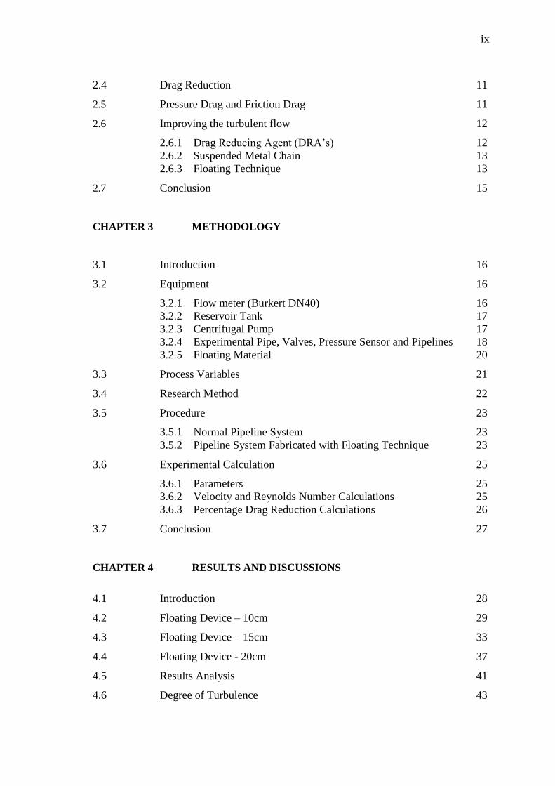
2.4 Drag Reduction 11
2.5 Pressure Drag and Friction Drag 11
2.6 Improving the turbulent flow 12
2.6.1 Drag Reducing Agent (DRA’s) 12
2.6.2 Suspended Metal Chain 13
2.6.3 Floating Technique 13
2.7 Conclusion 15
CHAPTER 3 METHODOLOGY
3.1 Introduction 16
3.2 Equipment 16
3.2.1 Flow meter (Burkert DN40) 16
3.2.2 Reservoir Tank 17
3.2.3 Centrifugal Pump 17
3.2.4 Experimental Pipe, Valves, Pressure Sensor and Pipelines 18
3.2.5 Floating Material 20
3.3 Process Variables 21
3.4 Research Method 22
3.5 Procedure 23
3.5.1 Normal Pipeline System 23
3.5.2 Pipeline System Fabricated with Floating Technique 23
3.6 Experimental Calculation 25
3.6.1 Parameters 25
3.6.2 Velocity and Reynolds Number Calculations 25
3.6.3 Percentage Drag Reduction Calculations 26
3.7 Conclusion 27
CHAPTER 4 RESULTS AND DISCUSSIONS
4.1 Introduction 28
4.2 Floating Device – 10cm 29
4.3 Floating Device – 15cm 33
4.4 Floating Device - 20cm 37
4.5 Results Analysis 41
4.6 Degree of Turbulence 43
x
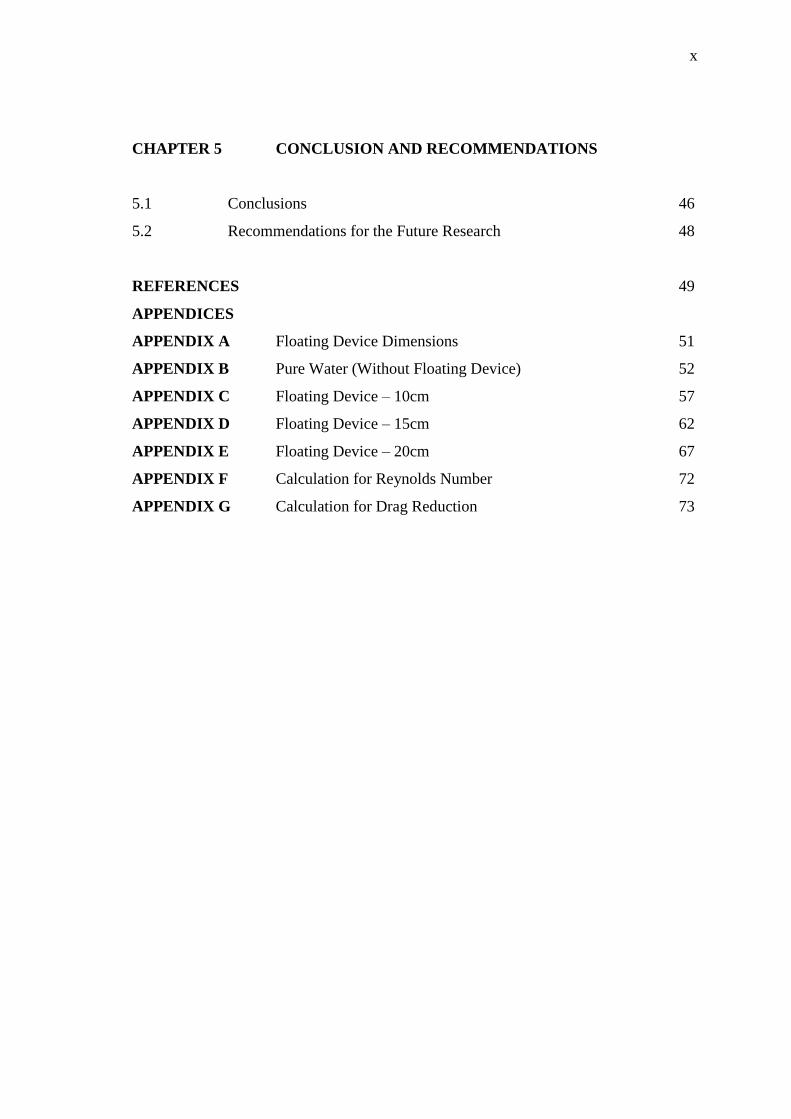
CHAPTER 5 CONCLUSION AND RECOMMENDATIONS
5.1 Conclusions 46
5.2 Recommendations for the Future Research 48
REFERENCES 49
APPENDICES
APPENDIX A Floating Device Dimensions 51
APPENDIX B Pure Water (Without Floating Device) 52
APPENDIX C Floating Device – 10cm 57
APPENDIX D Floating Device – 15cm 62
APPENDIX E Floating Device – 20cm 67
APPENDIX F Calculation for Reynolds Number 72
APPENDIX G Calculation for Drag Reduction 73
xi
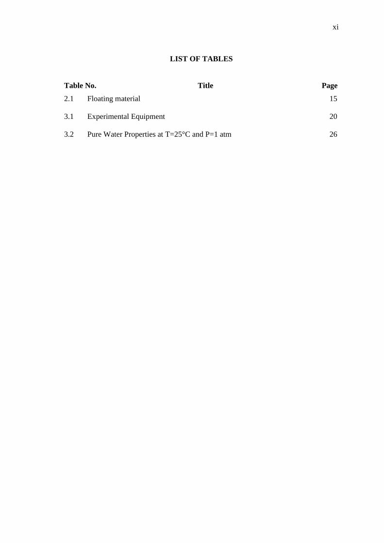
LIST OF TABLES
Table No. Title Page
2.1 Floating material 15
3.1 Experimental Equipment 20
3.2 Pure Water Properties at T=25°C and P=1 atm 26

xii
LIST OF FIGURES
Figure No. Title Page
2.1 Types of flow 8
2.2 Three type of flow 9
2.3 Turbulent Flow 10
3.1 Flow meter fixed in Experimental rig (FKKSA Laboratory) 18
3.2 Reservoir Tank 18
3.3 Centrifugal Pump 19
3.4 Floating Equipment 21
3.5 Fabrication of Floating Device 22
3.6 Process variable flowchart 24
3.7 Process flow of experiment 25
3.8 Schematic Diagram - Experimental Rig for Drag Reduction Analysis 25
3.9 Experimental Rig for Drag Reduction Analysis 26
4.1 Drag Reduction (%) versus Reynolds Number (Pipe Section – 0.5m) 30
for FD-10cm
4.2 Drag Reduction (%) versus Reynolds Number (Pipe Section – 1.0m) 31
for FD-10cm
4.3 Drag Reduction (%) versus Reynolds Number (Pipe Section – 1.5m) 32
for FD-10cm
4.4 Drag Reduction (%) versus Reynolds Number (Pipe Section – 2.0m) 33
for FD-10cm
4.5 Drag Reduction (%) versus Reynolds Number (Pipe Section – 0.5m) 34
for FD-15cm
4.6 Drag Reduction (%) versus Reynolds Number (Pipe Section – 1.0m) 35
for FD-15cm
4.7 Drag Reduction (%) versus Reynolds Number (Pipe Section – 1.5m) 36
for FD-15cm

xiii
4.8 Drag Reduction (%) versus Reynolds Number (Pipe Section – 2.0m) 37
for FD-15cm
4.9 Drag Reduction (%) versus Reynolds Number (Pipe Section – 0.5m) 38
for FD-20cm
4.10 Drag Reduction (%) versus Reynolds Number (Pipe Section – 1.0m) 39
for FD-20cm
4.11 Drag Reduction (%) versus Reynolds Number (Pipe Section – 1.5m) 40
for FD-20cm
4.12 Drag Reduction (%) versus Reynolds Number (Pipe Section – 2.0m) 41
for FD-20cm
4.13 Drag Reduction (%) Versus Reynolds Number (Pipe Length 1m) 42
4.14 Drag Reduction (%) Versus Reynolds Number (Pipe Length 1.5m) 43
4.15 Pressure drop influenced by the floating device of 10cm, 15cm and 44
20cm length on 1.5m pipe at Re = 74083.33
4.16 Pressure drop influenced by the floating device of 10cm, 15cm and 44
20cm length on 2m pipe at Re = 95250.00
4.17 Illustration of Floating Device 45
4.18 Floating Device in Turbulence Flow 45
4.19 The Mechanisms of Floating Device in Turbulence Flow 46
xiv
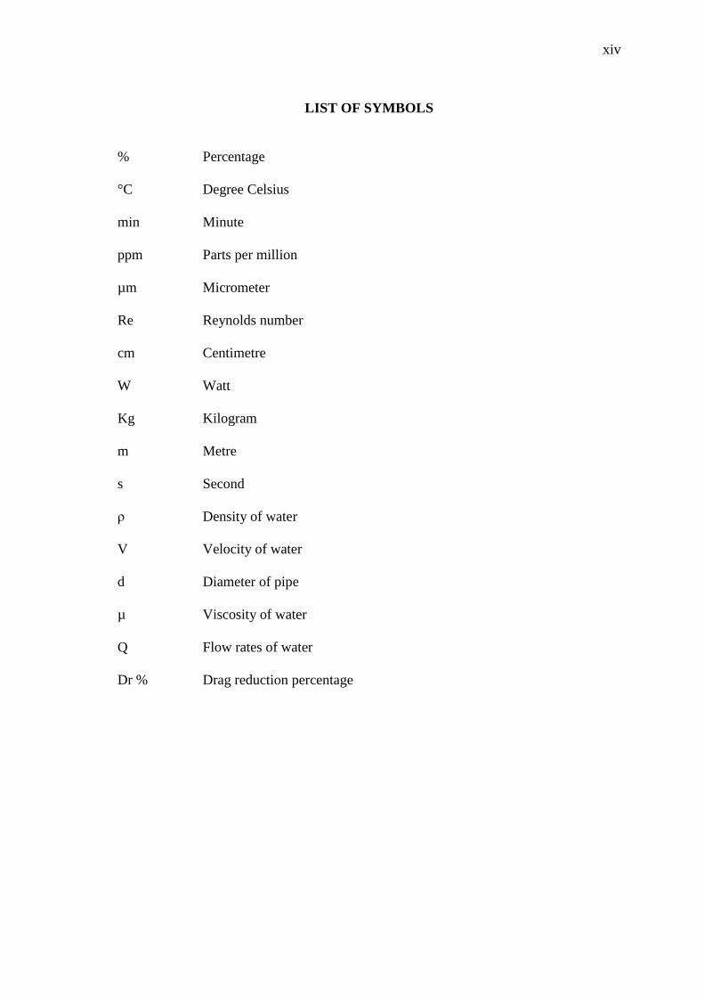
LIST OF SYMBOLS
% Percentage
°C Degree Celsius
min Minute
ppm Parts per million
µm Micrometer
Re Reynolds number
cm
Centimetre
W Watt
Kg Kilogram
m Metre
s Second
ρ Density of water
V Velocity of water
d Diameter of pipe
µ Viscosity of water
Q Flow rates of water
Dr % Drag reduction percentage
xv
LIST OF ABBREVIATIONS
P Pump
T Tank
PT Pressure Transmitter
MV Valve
PVC Polyvinyl Chloride

1
CHAPTER 1
INTRODUCTION
1.1 BACKGROUND OF THE STUDY
Pipelines transportation is widely used regardless in any industry. Most
commonly, liquid and gases are sent using the transportation method through a pipe
(Herberg et. al, 2000). In industry, pipelines are one of the most important tools among
the many utilities. Pipelines are widely needed in water supply, sewer, telephone lines,
oil pipelines and natural gas pipelines which tucked under our streets, through
neighbourhoods and communities, stretched across farms, forests, and deserts. These
pipelines also provide fuel to generate electricity and fertilizers to increase crop
production (A. Basu, 2010). Pipelines also collect crude oil from many rural areas and
deliver that crude oil to refineries and chemical plants to create all the products that
come from petroleum and petrochemicals (L.Mansingh, 2007). Therefore, an effective
pipeline flow is needed in order to reduce the pressure drop and drag reduction for
better and improved flow in the pipeline system.
There are three types of flow in pipeline systems, laminar flow, transitional and
turbulent flow. This research will be on the turbulence flow in pipeline systems.
Turbulent flow has a Reynolds number above 4000 which is type of fluid regime
characterized by stochastic property changes (J. Mathieu.2000). Turbulence in pipeline
causes the formation of eddies of many different length scales. These eddies which
enhance the unsteady vortices appearance in pipe flow on many scales and interact with
each other. In this case, the drag due to boundary layer skin friction increases thus
resulting in a reduction of overall drag (W. Cabot et. al. 1999). Drag Reduction is the

2
difference in fictional pressure drop along a segment of pipeline at a constant flow rate.
If the high drag reduction is obtained then the pipeline flow can be improved.
Pressure drop is the major problems that need to be catered in pipeline system.
In pipeline, pressure drop is a term used to describe the decrease in pressure from one
point in a pipe or tube to another point downstream (Britannia Enclylopedia.2002). The
occurrence of pressure drop results in frictional forces on the fluid as it flows through
the tube. The frictional forces are caused by a resistance to flow during a fluid
transportation. Pressure drop is an important factor which affects the flow behaviour
and pipeline efficiency. When designing piping systems, turbulent flow requires a
higher input of energy from a pump (Gasso, 2003). Even high pressure is given at the
initial stage, the pressure drop in the pipeline transportation proved to be a major
problem.
Many researches have been done to improve the flow in the pipeline system and
there are always room for betterment and new implementation. Previously, research has
been done to improve the flow in the pipeline by adding polymers, fibers or amphilic
solutes (known as surfactants). The previous surfactant research results in more than
70% of drag reduction (G. Albert. 2002). White and Savins reported that when
surfactant solutions flow through hydraulically smooth pipes of different diameters, the
drag reduction loss occurs at the constant critical wall shear stress τ,w,c, independent of
the pipe diameter. Their drag reduction has reached 73.7% (J. Rozanski.2010). This
research has its flaws as well when considering the recovery of the transported fluid.
The addition of surfactants needs fluid recovery in order to remove the added polymers.
In short, purification of the transported fluid will be the last process of the fluid before it
can be used. This will result in addition to operational cost. Application of a drag
reducing surfactant in the heating circuit also results up to 90% of drag reduction at
surfactants temperature of 70°C (J.Myska.2002). Yet, this system needs external heating
device to enhance the drag reduction. This research introduces new method by using the
floating technique without any added external force. Floating technique requires a set of
material which is elastic in nature and easy to float in water. Therefore, rubber material
is chosen to execute this research. This research is able to produce positive results thus
give huge impact in the industry of pipeline flow.
3
This research is conducted by designing an experimental work using the
fabricated floating equipment. The length of the floating material used in this technique
and the testing pipe length was the variable in this research. The effect of these two
variables was carefully investigated and the best length was selected. The best length
was further analysed with different variables such as flow rates and the pipe length. In
conclusion this research is novel and requires theoretical studies and experimental work
to strengthen the research outcome.
1.2 PROBLEM STATEMENT
Drag reduction and pressure drop are the major problem in turbulent flow in
pipeline systems. Pressure drop is the result of frictional forces and formation of eddies
on the fluid as it flows through the tube. The frictional forces are caused by a resistance
to flow. Formation of eddies results in pressure drop in turbulence flow. These
parameters reduce the efficiency and the performance of pipeline systems. In order to
improve flow in pipeline systems, these two parameters needs to be look after. The
previous studies on the drag reduction by using the additives such as polymer were
sufficient up to 70%. But, the cost of fluid recovery after the fluid transportation needs
to be taken into consideration. Addition in operational cost as well as pump failure due
to accumulation of these particles results in maintenance cost. Therefore, a new
technique of pipeline improvisation is needed in order to cater these problems. In this
research, floating technique does not require any fluid recovery process. There will be
no pump failure and there is no need for external power added to this technique. The
effect of floating technique has the potential breakthrough in pipeline industry by
competing with the previous research. Usage of the floating technique in turbulence
flow is easy to fabricate and handle. There is huge commercial value for this technique,
since it is applicable for any pipeline.
4
1.3 RESEARCH OBJECTIVES
i. To design a new technique to improve the water flow in pipelines
replacing the usage of chemical additives
ii. To study the effect of the design parameters (dimensions of the floating
object)
iii. To study the effect of the liquid circulation parameters (liquid flow rate,
and testing section lengths)
1.4 RESEARCH QUESTIONS
i. How to improve the water flow in pipeline?
ii. What are the effects of the design parameters on the water flow?
iii. What are the effects of the liquid circulation parameters on the water
flow?
1.5 SCOPE OF STUDY
The scope of study of this research is focused on improving the water flow by
using floating technique. The flow improvement of the water was analysed by
calculating the performance of drag reduction. Improving the pipeline flow means
increase the flow and directly reduce the pressure as well as reduce the degree of the
turbulence. The drag reduction needs to be improved in order to obtain an optimum
performance of the pipe flow. In this research, the floating technique was introduced
with three different length of rubber. Fabrication of rubber inside the pipeline is the cost
effective technique. The research scope was involved in turbulence flow by using the
floating technique without any external forces to the fabricated floating material. The
variables of this research are the length of rubbers, the testing pipe length. Other
parameters such as the flow rate, type of fluid, type of pipe, the size (diameter) of the
pipe, and related pipe specification was set to be constant in order to analyse the
variables in this research. The selection of the best rubber length (10cm, 15cm, and
20cm) on the different pipe length is the major scope of this research. The result of this
5
research satisfies the main objective which is to improve drag reduction, pumping
power saving and improving flow inside pipelines.
1.6 SIGNIFICANCE OF STUDY
This research enables the new implementation in pipeline system. The method
of fabricating the floating equipment with rubber material is cheap and save way to
improve the turbulent flow. There is no research have been done on pipe flow
improvisation by using floating technique. Costing is the major problem in previous
drag reduction studies. This research is geared up with cost effective and applicable
technique in industry. The ability of this study to produce positive result with more than
20% on the drag reduction in turbulent flow is proved to be applicable in pipeline
industry. The implementation of this technique in piping industry with set a benchmark
in the fluid transportation industry. This research has high commercial value in the
industry of pipeline transportation system. The novelty of this research enables us to
pattern the research for further publication and commercialisation. A series of
investigation is proposed to be followed after the execution of this novel research.
1.7 DEFINITION OF TERMS
1.7.1 Floating technique
Floating technique is term used to describe the suspension of the selected
material (rubber) in the turbulence flow. The floating technique is carried
out by fabricating the floating equipment in the pipeline. The fabrication of
rubber on a ring of aluminium holder is secured in pipeline. This term is
specially defined in order to describe the method used in this research.
1.7.2 Turbulence flow
Type of fluid (gas or liquid) flow in which the fluid undergoes irregular
fluctuations, or mixing, in contrast to laminar flow, in which the fluid moves
in smooth paths or layers. In turbulent flow the speed of the fluid at a point

6
is continuously undergoing changes in both magnitude and direction. The
flow of wind and rivers is generally turbulent in this sense, even if the
currents are gentle. The air or water swirls and eddies while its overall bulk
moves along a specific direction. (Britannia Encyclopaedia. 2002)
1.8 CONCLUSION
This chapter explains the detailed information of research restrictions and topic
background. The introduction begins with the background of studies which filled with
compact content concerning the field of research and the research impact towards the
industry. The field of the research and the aims to fulfil were set in research objectives
and research questions. The research flow of content and its boundary has been set in a
frame under the scope of research. The significant of this study which involves in
pipeline system have high commercial value in the industry not only nationally but
internationally it is very important. The continuation of this research will be followed
by chapter two which is known as the literature review.

7
CHAPTER 2
LITERATURE REVIEW
2.1 INTRODUCTION
The pipelines transport is broadly used in various industries. Any form of liquid
and gases are sent using the transportation method through a pipeline system. As
discussed in previous chapter, the pipeline system is the heart for transportation field.
An effective pipeline system is needed in order to save the pumping power and increase
the efficiency of pipeline systems.
In this research, the turbulent flow in pipeline system was studied. The major
factors which affect the turbulent flow are the pressure drop and drag reduction.
Therefore, both parameters need to be improved in order to obtain maximum flow in
pipeline system. In this study, the water flow in pipeline was improvised by using
floating technique. This novel idea need to be further analysed to improve the efficiency
of floating technique phenomena in turbulence flow.
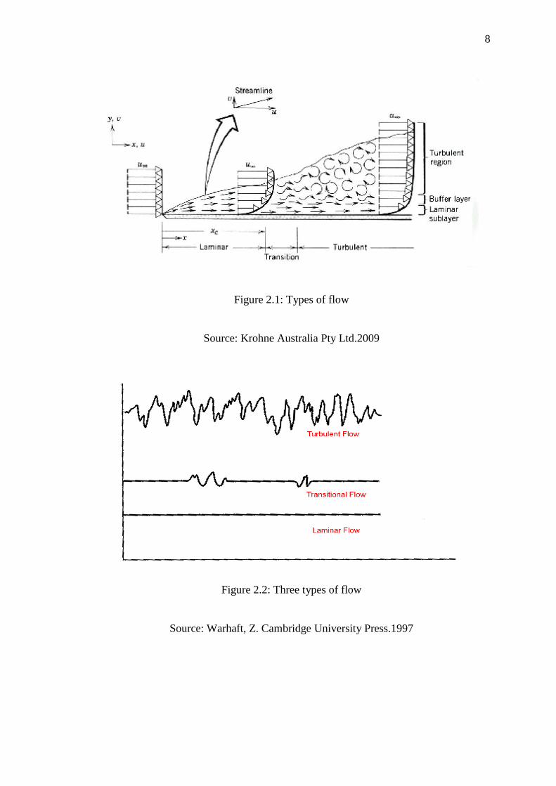
2.2 TYPES OF FLOW
When a fluid flows through a pipe, different parts flow at different speeds. Fluid
flow can be laminar, transitional or turbulent. Reynolds number used to characterize
different flow regimes, such as laminar or turbulent flow (Streeter, 1962). Reynolds
number is a dimensionless number that gives a measure of the ratio of inertial forces to
viscous forces and thus quantifies the relative significance of these three types of forces
for given pipe flow conditions (Wiggins and Goldstein, 1998). In this research, the
floating technique is involved with turbulence flow.
8
Figure 2.1: Types of flow
Source: Krohne Australia Pty Ltd.2009
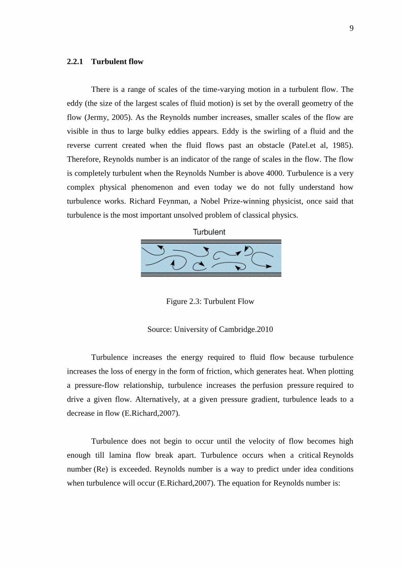
Figure 2.2: Three types of flow
Source: Warhaft, Z. Cambridge University Press.1997
9
2.2.1 Turbulent flow
There is a range of scales of the time-varying motion in a turbulent flow. The
eddy (the size of the largest scales of fluid motion) is set by the overall geometry of the
flow (Jermy, 2005). As the Reynolds number increases, smaller scales of the flow are
visible in thus to large bulky eddies appears. Eddy is the swirling of a fluid and the
reverse current created when the fluid flows past an obstacle (Patel.et al, 1985).
Therefore, Reynolds number is an indicator of the range of scales in the flow. The flow
is completely turbulent when the Reynolds Number is above 4000. Turbulence is a very
complex physical phenomenon and even today we do not fully understand how
turbulence works. Richard Feynman, a Nobel Prize-winning physicist, once said that
turbulence is the most important unsolved problem of classical physics.
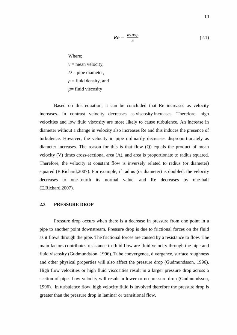
Figure 2.3: Turbulent Flow
Source: University of Cambridge.2010
Turbulence increases the energy required to fluid flow because turbulence
increases the loss of energy in the form of friction, which generates heat. When plotting
a pressure-flow relationship, turbulence increases the perfusion pressure required to
drive a given flow. Alternatively, at a given pressure gradient, turbulence leads to a
decrease in flow (E.Richard,2007).
Turbulence does not begin to occur until the velocity of flow becomes high
enough till lamina flow break apart. Turbulence occurs when a critical Reynolds
number (Re) is exceeded. Reynolds number is a way to predict under idea conditions
when turbulence will occur (E.Richard,2007). The equation for Reynolds number is:
10
(2.1)
Where;
v = mean velocity,
D = pipe diameter,
ρ = fluid density, and
µ= fluid viscosity
Based on this equation, it can be concluded that Re increases as velocity
increases. In contrast velocity decreases as viscosity increases. Therefore, high
velocities and low fluid viscosity are more likely to cause turbulence. An increase in
diameter without a change in velocity also increases Re and this induces the presence of
turbulence. However, the velocity in pipe ordinarily decreases disproportionately as
diameter increases. The reason for this is that flow (Q) equals the product of mean
velocity (V) times cross-sectional area (A), and area is proportionate to radius squared.
Therefore, the velocity at constant flow is inversely related to radius (or diameter)
squared (E.Richard,2007). For example, if radius (or diameter) is doubled, the velocity
decreases to one-fourth its normal value, and Re decreases by one-half
(E.Richard,2007).
2.3 PRESSURE DROP
Pressure drop occurs when there is a decrease in pressure from one point in a
pipe to another point downstream. Pressure drop is due to frictional forces on the fluid
as it flows through the pipe. The frictional forces are caused by a resistance to flow. The
main factors contributes resistance to fluid flow are fluid velocity through the pipe and
fluid viscosity (Gudmundsson, 1996). Tube convergence, divergence, surface roughness
and other physical properties will also affect the pressure drop (Gudmundsson, 1996).
High flow velocities or high fluid viscosities result in a larger pressure drop across a
section of pipe. Low velocity will result in lower or no pressure drop (Gudmundsson,
1996). In turbulence flow, high velocity fluid is involved therefore the pressure drop is
greater than the pressure drop in laminar or transitional flow.

11
2.4 DRAG REDUCTION
The remarkable ability of low concentrations of certain additives to reduce the
frictional resistant in turbulent flow to as low as one-quarter that of the pure solvent is
known as drag reduction (McCormick.1995). The phenomenon of drag reduction has
been studied experimentally mainly in channels and pipes. In that case the reduction in
drag manifests itself as a change in the relation between the mean pressure drop P over
the channel/pipe and the flow rate Q the flow rate is increased if the pressure drop is
kept constant, or the pressure drop goes down if the flow rate is kept constant (K.F.
Wakker,1996). The phenomenon of drag reduction, reported for the first time by the
British chemist Toms in 1949, is probably the effect produced by polymer addiction in
fluids which has attracted the most attention, because of its relevance for applications.
This implies the determining drag reduction by using the formula below:
(2.2)
The pressure drop at normal condition and the pressure drop occurrence after the
fabrication of floating equipment in the pipeline will be measured. The percentage of
drag reduction of the pipeline will be analysed using the drag reduction equation. The
positive result can be obtained when the drag reduction percentage is above 20%.
2.5 PRESSURE DRAG AND FRICTION DRAG
Drag force can be classified as the net force exerted by fluids as a result of
combined effect of wall shear and pressure forces (Cengel, 2006). The drag due to shear
stress is known as skin friction drag while drag due to pressure is known as pressure
drag (Cengel, 2006). According to Osborne Reynold, Reynolds number is inversely
proportional to viscosity of the fluid. Therefore, the friction drag at very high Reynolds
numbers is negligible (Cengel, 2006). Therefore the drag reduction in this research is
categorized as drag reduction due to pressure drag.
12
2.6 IMPROVING THE TURBULENT FLOW
Many researches had been done to improve the turbulent flow in pipelines. A
series of investigation by adding additives, surfactants, polymers and even natural
mucilage were used as drag reducing agent in turbulent flow. These researches were
success with more than 70% of drag reduction. Apart from that, suspended solids such
as metal powder were also used in order to improve the turbulent flow. Recently,
assembled chain was fabricated in pipeline and the effect of the suspended chain on the
drag reduction were analysed.
2.6.1 Drag Reducing Agents (DRAs)
Drag reduction is due to boundary layer skin friction. The structure and location
of boundary layer separation often changes, sometimes resulting in a reduction of
overall drag (Joline.et al, 2006). The flow can be driven by pumps providing a pressure
head that overcomes the wall friction or the drag in the flow. The drag reduction is a
major problem even though maximum pumping power is consumed. To save the
pumping power a drag reducing agent is vital. Many researches have been done to
overcome this problem as well to improve the existing flow system. A drag reducing
agent, also called a flow improver, is a long chain polymer chemical that is used in
crude oil, refined products or non-potable water pipelines (Havard, 2006). It is injected
in small amounts (parts per million) and is used to reduce the frictional pressure drop
along the pipeline's length (Havard, 2006). “Drag reduction for liquid flow in a pipe or
channel flow is commonly achieved by adding chemicals such as surfactants or
polymers to the liquid. Through the formation of surfactant micelles or polymer chains
in the bulk liquid, the frequency of formation and size of the turbulence eddies can be
dampened. This results in the boundary layer in the pipe wall becoming less turbulent,
resulting in less drag in the liquid flow.” (Joline,et al,2006). By dissolving a minute
amount of long-chained polymer molecules in water, the frictional drag of turbulent
flow could be reduced dramatically. In pipe flows, for example, the drag could be
reduced up to 70 % by adding just a few parts per million (ppm) of polymer
(Tom,1977). In years time, drag reducing agent were used to improvise the pipe flow.
After considering the pros and cons of the previous studies, new design is created in
44
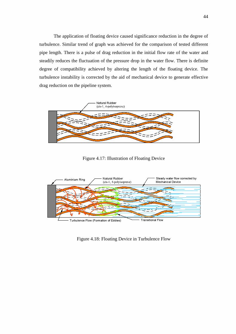
The application of floating device caused significance reduction in the degree of
turbulence. Similar trend of graph was achieved for the comparison of tested different
pipe length. There is a pulse of drag reduction in the initial flow rate of the water and
steadily reduces the fluctuation of the pressure drop in the water flow. There is definite
degree of compatibility achieved by altering the length of the floating device. The
turbulence instability is corrected by the aid of mechanical device to generate effective
drag reduction on the pipeline system.
Figure 4.17: Illustration of Floating Device
Figure 4.18: Floating Device in Turbulence Flow