“i hereby admit that have read this report and from my...
TRANSCRIPT

i
“I hereby admit that have read this report and from my point of view this report is
enough in term of scope and quality for purpose for awarding
Bachelor of Degree in Mechanical Engineering (Thermal-Fluid)”
Signature : ………………………….
Supervisor Name I : ………………………….
Date : ………………………….
Signature : ………………………….
Supervisor Name II : ………………………….
Date : ………………………….
HEAT TRANSFER CHARACTERICSTIC OF A CONDENSERWITH Al2O3
REFRIGERANT BASED NANOFLUIDS AS WORKING FLUID
NICHOLAS LIAN AK MUJAH
This report presented to fulfill the requirement in term to obtain
Bachelor of Degree in Mechanical Engineering (Thermal-Fluid)
Fakulti Kejuruteraan Mekanikal
Universiti Teknikal Malaysia Melaka
MAY 2012

ADMISSION
“I admit this report has been written by me myself except for some quotation that has
been noted well for each of them”
Signature :……….………………………
Author Name :……….………………………
Date :……………………………….

DEDICATION
This report is dedicated to my beloved parents
Mujah @Tumbin ak Enjawan
and
Rosemina ak Outram
APPRECIATION
First of all, thanks God for His almighty that I can complete this report. Thus,
thanks also to my beloved parents that always support me although they are far away
from me. Special thanks to my supervisor, Pn. Fadhilah bt Shikh Anuar in guiding me
along this report writing and project computation.
To all my friends especially my course mates who never give up in supporting
me towards the completion of this report. I am appreciating all the helps and supports.
ABSTRACT
Refrigeration systems have become very important in various applications.
Almost all buildings and houses in Malaysia have the air conditioning system regarding
the hot temperature in this country. However, the use of the air conditioners consumes a
lot of electricity. Scientist and researchers are trying to find a new kind of working fluid
that can enhance the thermal conductivity and the pressure drop of the conventional base
fluid, thus increasing the heat transfer rate and the energy consumption could be
reduced. By introducing a base fluid suspended with nanoparticles which have been
developed in recent years, this might happen. In this project, the effect of the suspended
nanoparticles, Al2O3, in the base fluid; conventional refrigerant, Tetraflurocarbons, R-
134a, called as nanorefrigerant, is being investigated through mathematical modeling to
investigate the thermal conductivity, pressure drop and heat transfer of nanorefrigerant
with different volume fraction of nanoparticles from 0.2% - 1.0%. CFD simulation is
needed in this project to verify the results of mathematical modeling. Based on the
calculation, the percentage of thermal conductivity improvement of nanorefrigerant as
compared to conventional refrigerant is 1256.125% and 16 – 48% enhancement with
0.2% to 1.0% volume fraction of nanoparticles. Meanwhile the pressure drop showed the
enhancement about 61.8% and heat transfer enhancement is about 2.09%. The results of
mathematical modeling are higher as compared to simulations result. These showed that
with additive of nanoparticles, the properties of conventional refrigerant can be improve
for better cooling process.

ABSTRAK
Sistem penyejukan adalah amat penting didalam banyak aplikasi. Di Malaysia
sahaja, ia boleh dilihat hampir setiap bangunan dan rumah memandangkan keadaan suhu
yang agak panas di negara ini. Walaubagaimanapun, penghawa dingin menggunakan
banyak tenaga elektrik. Para saintis dan penyelidik masih sedang mencari satu bendalir
kerja yang baru untuk meningkatkan kekonduksian terma dan penurunan tekanan
bendalir asas konvensional, sekali gus meningkatkan kadar pemindahan haba dan
penggunaan tenaga dapat dikurangkan. Dengan potensi nanopartikel yang telah
dibangunkan sejak beberapa tahun kebelakangan ini, impian mungkin menjadi
kenyataan. Dalam projek ini, kesan nanopartikel, Al2O3 yang dimasukkan ke dalam
bendalir penyejuk yang biasa, yang boleh dipanggil sebagai nanorefrigerant, sedang
disiasat menggunakan pemodelan matematik dari segi kekonduksian terma, penurunan
tekanan dan kadar pemindahan haba daripada nanofluids dengan menggunakan
kepekatan nano partikel 0.2–1.0%. Simulasi diperlukan dalam projek ini untuk
mengesahkan keputusan pemodelan matematik kerana ia adalah lebih tepat. Berdasarkan
pengiraan, peratus kekonduksian terma bagi nanorefrigerant meningkat jika
dibandingkan dengan bendalir asalnya iaitu1256.125% dan 16 – 48%peningkatan
dengan 0.2 – 1.0%kepekatan nanopartikel. Sementara itu penurunan tekanan juga
menunujukkan peningkatan sebanyak 61.8% dan peningkatan kadar pemindahan haba
sebanyak 2.09%. Keputusan agi permodelan matematik adalah lebih tinggi jika
dibandingkan dengan keputusan simulasi. Ini menunujukan dengan menambahkan
nanopartikel, sifat bendalir asal boleh ditingkatan untuk proses penyejukan yg lebih
baik.
TABLE OF CONTENTS
CHAPTER PAGE
ADMISSION
i
DEDICATION ii
APPRECIATION iii
ABSTRACT iv
ABSTRAK v
TABLE OF CONTENTS x
LIST OF TABLES xii
LIST OF FIGURES xii
CHAPTER 1 1
INTRODUCTION 1
1.1 Background Study 2
1.2 Objectives 2
1.3 Scope 3
1.4 Problem Statement 3
CHAPTER 2 4
LITERATURE RIVIEW 4
2.1 Refrigeration System 4
2.2 Component of Refrigerant System-Condenser 6
2.3 Nanorefrigerant 7
2.4 Thermal Conductivity of Nanorefrigerant 11
2.5 Pressure Drop of Nanorefrigerant 25
2.6 Heat Transfer of Nanorefrigerant 29

CHAPTER 3 36
METHODOLOGY 36
3.1 Introduction 36
3.2 Design and Physical Properties of Condenser 37
3.3 Mathematical Modeling 39
3.3.1 Thermal Conductivity 39
3.3.2 Pressure Drop 40
3.3.3 Heat Transfer 41
3.4 Simulation using CFD 42
3.4.1 Simulation set ups 42
CHAPTER 4 44
RESULTS AND DISCUSSION 44
4.1 Introduction 44
4.2 Calculations Result 45
4.2.1 Thermal Conductivity 45
4.2.2 Pressure Drop 46
4.2.3 Heat Transfer rate 48
4.3 Simulation Data 49
4.3.1 Thermal Contours 49
4.3.2 Pressure contours 52
4.3.3 Heat Transfer rate 52
4.4 Discussions 54
4.4.1 Surface Area Impact 54
4.4.2 Interfacial Layer Impact 55
4.4.3 Brownian motion 56
4.5 Different between simulation and calculation data 57
CHAPTER 5 36
CONCLUSION AND RECOMMENDATIONS 58
5.1 Conclusion 58
5.2 Recommendations 59

REFERENCES 60
APPENDIXES A Gantt chart 62
APPENDIXES B FLUENT ANSYS simulation 72
APPENDIXES C Workbenches Schematic 72
APPENDIXES D Thermal conductivity enhancement percentage
(calculation)
73
APPENDIXES E Pressure drop enhancement percentage (calculation) 73
APPENDIXES F Heat Transfer enhancement percentage (calculation) 74

LIST OF TABLES
TABLE CONTENTS PAGE
Table 2.1 The selective summary of the thermal conductivity enhancement
in Al2O3-based nanofluids
15
Table 2.2 Summary of experiment on convective heat transfer of nanofluids 32
Table 3.1 Physical properties of Al2O3 nanoparticles and refrigerant, R-134a 38
Table 3.2 Constant perimeters 38
Table 3.3 Simulation steps 42
Table 4.1 Thermal Conductivity Data 45
Table 4.2 Pressure Drop Data 47
Table 4.3 Heat Transfer Data 48
Table 4.4 Temperature Contours 49
Table 4.5 Simulations Heat Transfer Data 53

LIST OF FIGURES
FIGURES CONTENTS PAGE
Figure 2.1 Aluminum oxide particles, Al2O3 9
Figure 2.2 Cooper oxide particles, CuO 9
Figure 2.3 Comparison of some experimental data on thermal conductivity
for aluminum oxide
14
Figure 2.4 Comparison of the experimental nanoparticle impact factors with
the predicted values by the nanoparticle impact factor equation
27
Figure 2.5 Laminar flow heat transfer comparison. 34
Figure 2.6 Laminar flow heat transfer comparison for different L/D values. 34
Figure 2.7 Nusselt number vs. Reynolds number in laminar flow. 35
Figure 2.8 Effect of volume fraction on Nusselts number. 35
Figure 3.1 Project flowchart 37
Figure3.2 Horizontal smooth tube condenser 38
Figure4.1 Thermal Conductivity versus Volume Fraction graph 45
Figure4.2 Pressure Drop versus Volume Fraction graph. 46
Figure4.3 Heat Transfer Vs Volume Fraction. 48
Figure4.4 Pressure Contours 52
Figure4.5 Comparison between calculations and simulations heat transfer
data.
52
Figure4.6 Rubik Cubes 54
Figure4.7 Schematic cross section of nanofluid structure consisting of
nanoparticles, bulk liquid, and nanolayers at solid/liquid interface
55
NOMENCLATURE
A Area(
2m ) xB2 Depolarization factor along x- symmetrical
axis c constant pC Heat capacity( KkgJ ./ ) d Diameter (m) f
friction
h Heat transfer coefficient( KmW 2/ ) k Thermal Conductivity ( KmW ./ ) ck33
Longitudal equivalent thermal conductivity
ck11 Transverse equivalent thermal conductivity L Length (m) Nu Nusselt number Pr Prandtl number Re Reynold number r Radius (m) T Temperature ( Co
or K) T Temperature difference U Overall heat transfer coefficient ( KmW 2/ ) Greek Symbols Volume ratio Particle motion n Shape factor Density (
3/ mkg ) Volume Fraction Ratio of nano layer Elliptical complex nanoparticles v Velocity( sm / ) Viscosity( sPa. ) Particle sphericity Subscripts p Nanoparticles b Base fluid eff Effective pe Modified in Inlet out Outlet
1
CHAPTER 1
INTRODUCTION
1.1 Background Study
An air conditioner is a mechanism designed to extract heat from an area. The
whole process is done using the refrigerant cycle. The process consists of heating,
ventilation and air conditioning or usually referred as HVAC. HVAC is a form of air
treatment whereby temperature, ventilation and cleanliness are all controlled within
limits determined by the requirements of the air conditioned enclosure. In the HVAC
system, refrigerant is used.
A refrigerant is a substance used in air conditioning system. Usually,
fluorocarbons, especially chlorofluorocarbons, were used as refrigerants, but now they
are illegal because of their ozone depletion effects. Other common refrigerants used in
various applications are ammonia, sulfur dioxide, and non-halogenated hydrocarbons
such as methane.
In heat transfer, condenser is a device to condense gas state to liquid state,
typically by cooling it. Thus, and because of that, the latent will transfer to the coolant.
Condensers is actually a typical heat exchangers, which are used in so many industrial

2
needs.. For example, a refrigerator uses a condenser to get rid of heat extracted from the
interior of the unit to the outside air. Condensers are used in air conditioning, industrial
chemical processes such as distillation, steam power plants and other heat-exchange
systems. Use of cooling water or surrounding air as the coolant is common in many
condensers.
Nanorefrigerant might still a new technology out there. However, this technology
has a big potential to be commercialized as the result to its advantages. One of the
applicable nanotechnologies is nanofluid. Nanofluid is a mixer between nanoparticles
and based fluid. Examples of nanoparticles such as aluminum oxide, cooper oxide and
carbon nanotubes. While base fluids are such as DI water, ethylene glycol, and oil. The
nanoparticles suspense into any refrigerant called as nanorefrigerant in the refrigerant
system. This is regarding its benefits to enhance the performance of the refrigeration
system. When a substance in nano sized, it‟s actually change its properties and
somehow, it can benefit air conditioning system. Thus, because of that, nanofluid can
actually revolutionize the air conditioning system by introducing nanorefrigerant as the
new working fluid to replace the conventional base fluids.
1.2 Objectives
1) To investigate the effect of aluminum oxide nanoparticles with volume fraction
from 0.2 to 1.0 vol % on thermal conductivity of nanorefrigerant.
2) To study the effect of the nanoparticle volume fraction on pressure drop of the
nanorefrigerant.
3) To investigate the heat transfer rate of nanofluids in a condenser

3
1.3 Scope
This study will use mathematical modeling to investigate and determine the
thermal physical properties of the nanorefrigerant. The parameters such as size of
nanoparticles, types of refrigerant, nanorefrigerant velocity, and mass flux, heat flux
are constants. The only variable in this study is only the nanoparticle volume
fraction.
1.4 Problem Statement
Air Conditioning is very important nowadays. At current moment, refrigerant
fluids are used in the system. For example is R134a. Meanwhile, experts/scientists
believe that nanoparticles have great potential in enhancing the thermal conductivity
of the whole refrigeration system. The method is by mixing the nanoparticles with
base fluids to create nanorefrigerant.

4
CHAPTER 2
LITERATURE REVIEW
2.1 Refrigeration System
The refrigeration cycle is the series of events that occur to allow the refrigerant
to both absorb and release heat energy. The refrigeration system is divided into low-
pressure side and high-pressure side. There are two specific points within the
refrigeration system where the system divides: the compressor and the metering device.
The high side of the system begins with the compressor outlet and includes the
condenser and associated lines and ends at the metering device inlet. The low side of the
system begins at the outlet of the metering device and includes the evaporator and
associated lines and end sat the compressor (Cengel, 2006).
The compressor draws in low-pressure vapor from the suction line. In the
compressor, the refrigerant is pressurized, causing the temperature to increase relative to

5
the pressure applied. High-pressure, high-temperature refrigerant vapor exits the
compressor and travels through the discharge line to the condenser. (Cengel, 2006)
When the refrigerant reaches the condenser inlet, it is almost 100 percent vapor.
A small amount of liquid may remain. As the refrigerant moves from the top of the
condenser, it passes through the tubes. Much of the heat that is present within the vapor
is transferred to the tubes and fins of the condenser. As air moves across the surface of
the fins and tubes, heat is dissipated into the atmosphere. This process is aided by a ram
air effect provided by the movement of the vehicle and the operation of the cooling fan.
As the refrigerant moves down through the tubes on the condenser, much of the latent
heat stored in the vaporized refrigerant is released, causing the vapor to condense into a
liquid. (Carrigan et. al, 2006)
High-pressure liquid refrigerant exits the condenser into the liquid line, where it
is transported to the metering device. The metering device acts as a restriction, reducing
the amount of refrigerant pressure and volume. As the liquid passes through the
metering device, the pressure is reduced by approximately 75 percent or more. Because
pressure and temperature are relative to one another, the temperature of the refrigerant is
significantly reduced as the refrigerant exits the metering device. The refrigerant exits
the metering device as a low-pressure, low-temperature liquid. (Carrigan et. al, 2006)
Low-pressure, low-temperature liquid refrigerant enters the evaporator core. As
air is forces across the surface of the evaporator, heat that resides within the air is
absorbed by the evaporator core and into the refrigerant, causing the refrigerant to
vaporized, thus reducing the air temperature. As the air is cooled, moisture present in the
air molecules condenses on the surface of the evaporator. Refrigerant exits the
evaporator as a low-pressure, low-temperature vapor. The refrigerator cycle continues as
the low-pressure, low-temperature vapor refrigerant enters the compressor suction hose

6
and is transported to the compressor. At this point, the cycle starts over (Carrigan et. al,
2006).
2.2 Component of Refrigeration System – Condenser
The condenser is the next destination for the refrigerant after it leaves the
compressor. When the refrigerant leaves the compressor and enters the condenser, it
does so as a high-pressure, high-temperature vapor. The purpose of the condenser is to
remove enough heat from the gaseous refrigerant to cause a change of state into a high-
pressure liquid (Cengel, 2006).
The condenser is a heat exchanger is physically located at the front of the vehicle
and install in front of the radiator. The placement of the condenser allows for maximum
airflow to pass the condenser to provide maximum heat transfer (Cengel, 2006).
The condenser is constructed of a series of tubes that transport refrigerant.
Between each tube is a set of fins that provide surface area in which heat can be
dissipated. The basic design and operation is similar to that of a radiator. Refrigerant
enters at the top of the condenser and flows toward the outlet located at the bottom of the
core. As high-pressure refrigerant is force through the condenser, the heat that is present
within the refrigerant is transferred to the tubes and fins through the process of
conduction. As air is forced across the surfaces of the condenser, heat from the tubes and
fins is transferred into the atmosphere by convection. Sufficient heat is removed from
the refrigerant to cause the refrigerant to condense into a liquid refrigerant; hence the
name condenser (Cengel, 2006).

7
2.3 Nanorefrigerant
Refrigeration is very important nowadays especially in a country like Malaysia.
Since Malaysia is considered as hot country, thus chilling system is a must in their
households, offices and etc. However, the use of refrigeration system is quite a waste in
terms of energy. This is because, a refrigeration cycle required a lot of energy compared
to any electrical items such as lamps, and fans.
Refrigerants are the transport fluids which convey the heat energy from the low-
temperature level to the high-temperature level, where it can, in terms of heat transfer,
give up its heat. In the broad sense, gases involved in liquefaction processes or in gas-
compression cycles go through low-temperature phases and hence may be termed
“refrigerants,” in a way similar to the more conventional vapor-compression fluids.
Refrigerants are designated by number. The identifying number may be preceded
by the letter R, the word “Refrigerant,” or the manufacturer‟s trademark or trade name.
The trademarks or trade names shall not be used to identify refrigerants on equipment or
in specifications. In the previous time, chlorofluorocarbon (CFC) and hydro
chlorofluorocarbon (HCFC) are use as refrigerant in air conditioning system. However,
due to the “greenhouse effect”, these refrigerants have been phase out.
Nowadays, new refrigerants, primarily hydrofluorocarbon, HFCs, have been
commercialized to replace them. There has also been a renewed interest in non
halocarbon refrigerants such as ammonia and carbon dioxide.
Recently, the issue regarding refrigerant become hype topic once more. This time
is regarding the performance of heat transfer of the refrigerant itself. Various techniques

8
and development have been proposed to improve the heat transport properties of fluids.
At the beginning, researchers tried to blend or suspend the base fluid with solid particles
of micrometer, even millimeter magnitudes to increase the thermal conductivity of the
base fluid since the thermal conductivity of solid is typically higher than that of liquids
(Xiang and Mujumdar, 2006). Based on their research, they able to increase the thermal
conductivity of cooper up to 401 W/m.K and aluminums up to 237 W/m.K. Those are
metallic materials. For non-metallic, silicon and alumina, Al2O3, the thermal
conductivity increase up to 148 W/m.K and 40 W/m.K respectively. Others are metallic
liquid such as sodium and non-metallic liquid such as water, which were also enhanced
in terms of its thermal conductivity. However due to its large density and size,
practically it the applications are limited. Furthermore, by using micro particles, it may
cause abrasion of the surface, clogging the micro channels and increasing the pressure
drop (Zenghu Han et al, 2008).
Regarding this issues, researchers and scientists put one step forward.
This time they consider nanotechnology. Thus, it is leading to process and produce
materials with average crystallite sizes below 50 nm. Fluids with nanoparticles
suspended in them are called nanofluids, a term proposed by Choi in 1995 at the
Argonne National Laboratory, U.S.A. (Choi et al.1995).
Basically, nanofluids are formed by dispersing nanometer-sized particles (1-
100nm) or droplets into heat transfer fluid, HTFs usually use as refrigerant. The
specialty of nanofluids are they have unique properties, such as large surface area to
volume ratio, dimension-dependent physical properties, and lower kinetic energy, which
can exploits by the nanofluid. Furthermore, its large surface area makes nanoparticles
better and more stably dispersed in base fluids. Compared with micro-fluids or milli-
fluids, nanofluids stay more stable, so nanofluids are promising for practical
applications. Nanofluids will keep the fluidic properties of the base fluids, behave like
pure liquids and incur little penalty in pressure drop due to the fact that the dispersed
9
phase (nanoparticles) are extremely tiny, which can be very stably suspended in fluids
with or even without the help of surfactants ( Xuan and Li, 2003).
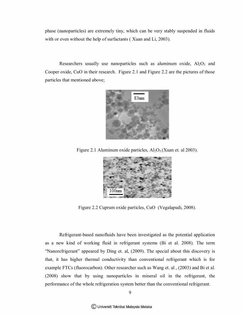
Researchers usually use nanoparticles such as aluminum oxide, Al2O3 and
Cooper oxide, CuO in their research. Figure 2.1 and Figure 2.2 are the pictures of those
particles that mentioned above;
Figure 2.1 Aluminum oxide particles, Al2O3.(Xuan et. al 2003).
Figure 2.2 Cuprum oxide particles, CuO (Vegalapudi, 2008).
Refrigerant-based nanofluids have been investigated as the potential application
as a new kind of working fluid in refrigerant systems (Bi et al. 2008). The term
“Nanorefrigerant” appeared by Ding et. al, (2009). The special about this discovery is
that, it has higher thermal conductivity than conventional refrigerant which is for
example FTCs (fluorocarbon). Other researcher such as Wang et. al , (2003) and Bi et al.
(2008) show that by using nanoparticles in mineral oil in the refrigerant, the
performance of the whole refrigeration system better than the conventional refrigerant.

10
Based on Wu et al. (2008) investigation on the boiling heat transfer
characteristics of nanorefrigerant are focused only on the pool boiling heat transfer and
there are no published researches on the flowing boiling heat transfer characteristics of
nanorefrigerant according to Peng et al. (2009).
In recent years, Park and Jung (2007 a, b) conducted an experiment on the pool
boiling heat transfer of CNT‟s/R22, CNT‟s/R123 and CNT‟s/R134a using horizontal
smooth tube. The result was quite shocked because at lower heat flux, the enhancement
of the heat transfer coefficients became clearer and the maximum enhancement could
reach 36.6%. The results of the experiment also showed that the pool boiling heat
transfer coefficients of refrigerants improved by using CNT‟s.
Meanwhile, from the experiment that was conducted by Trisaksri and
Wongwises (2009), they used a cylindrical copper tube to investigate the pool boiling
heat transfer of TiO2/HCFC 141b nanofluid. Their results were that, with the increments
of the concentrations of nanoparticles, the nucleate pool boiling heat transfer will
decreased, especially at high heat fluxes.

11
2.5 Thermal Conductivity of Nanorefrigerant
Generally, thermal conductivity is the property of a material which is its
ability to conduct heat. Heat transfer by conduction involves transfer of energy
within a material without any motion of the material as a whole. Conduction
happened when a temperature difference exists in a solid medium. Conductive
heat flow occurs when temperature is decreasing because higher temperature
generates higher molecular energy or more molecular movement. Energy is
transferred from the more energetic to the less energetic molecules when
neighboring molecules collide among themselves. In terms of unit, in
International System of Units (SI), thermal conductivity measured by watts per
meter Kelvin (W/m .K).
Murshed et al. (2007) stated that the thermal conductivity of nanofluids
varies with three attributes; size, shape and material of nanoparticles. For
example, nanofluids that are suspended with metallic nanoparticles were found to
have a higher thermal conductivity than nanofluids that are suspended with non-
metallic (oxide) nanoparticles. Furthermore, nanofluids that are suspended with
nanoparticles that are spherical in size increased only a smaller value of thermal
conductivity compared with the nanofluids having cylindrical (nano-rod or tube)
nanoparticles.
The less expensive nanoparticles that are usually used by researchers in
their experiment are Alumina (Al2O3) and Copper oxide (CuO) based on Xiang
and Mujumdar (2006). Even though the size of nano particles and refrigerants are
different, but still the thermal conductivity of the nanofluids till enhanced. There
is another experiment conducted by Eastman et al. (1997), showed that the
thermal conductivity of nanofluids that contains CuO, Al2O3 and Cu
nanoparticles with two different base fluids; water and HE 200 oil was measured.