i analysis of pro training systems(u) naval equipment ... · training systems(u) naval equipment...
TRANSCRIPT

I AD-A126 661 ANALYSIS OF PRO POSED SMOKE GENERATOR CONCEPTS FORTRAINING SYSTEMS(U) NAVAL TRAINING EQUIPMENT CENTER
ORLANDO FL E SWIATOSZ JAN 83 NAVTRAEQUIPC-IH-344
UN ASS F/G 5/9 NL
E~mmEmEEENEElE//Ig/EE/hEEEEEllllElllllIHuml//lril
I
1.8
MICROCOPY RESOLUTION TEST CHARTNATIONAL BUREAU Of STANDARDS 1963 A

TECHNICAL REPORT: NAVTRAEQUIPCEN IH-344
ANALYSIS OF PROPOSED SMOKE GENERATORCONCEPTS FOR TRAINING SYSTEMS
E. SwlatoszSimulation Concepts LaboratoryC Naval Training Equipment Center
Orlando, Florida 32813
March 1983 VFINAL REPORT
DoD DI'IUTION STATEMENT
Approved for Public Release.Distribution Unlimited.
88 04 0

TECHNICAL REPORT: NAVTRAEQUIPCEN IH-344
ANALYSIS OF PROPOSED SMOKE GENERATORCONCEPTS FOR TRAINING SYSTEMS
E. SwiatoszSimulation Concepts LaboratoryNaval Training Equpnent CenterOrlando, Florida 32813
March 1983FINAL REPORT
GOVERNMENT RIGHTS IN DATA STATEMENT
Reproduction of this publication in wholeor in part is permitted for any purposeof the United States Government
Approved by:
David P. GlennDirector of earch
A. 'M. SpoonerlHead, Advanced Simulation ConceptsLaboratory
tf
UNCLASS I FI EDSECURITY CLASSIFICATION OF THIS PAGE (Mhen D04 Entered)
REPORT DOCUMENTATION PAGE BFR CMTIc ORMI. REPORT NUMBER -- .,OVT ,cS9O9 NO , . rECIPIENTS CATALOG NUMMER
NAVTRAEQUI PCL* IH-344 W
4. TITLE (end SubTitle) S. TYPE OF REPORT 6 PERIOD COVERED
ANALYSIS OF PROPOSED SMOKE GENERATOR CONCEPTS Final ReportJan 81 to Jan 83FOR TRAINING SYSTEMS 6. PERFORMING ORG. REPORT NUMBECRNAVTRAEQUI PCE4-IH-344
7. AUTHOR(&) 6. CONTRACT OR GRANT kUMSER(*)
E. SWIATOSZ
S. PERFORMING ORGANIZATION NAME AND ADDRESS 10. PROGRAM ELEMENT. PROJECT. TASKAREtA I WOMK UNIT NUMBrMSAdvanced Simulation Concepts Laboratory NAVTRAEQUIPCEN
Naval Training Equipment Center Ta 2732
Orlando, Florida 32813 Task 2732I. CONTROLLING OFFICE NAME ANO ADDRESS 12. REPORT DATE
Naval Training Equipment Center January 198313. NUMMER OF PAGESOrlando, Florida 32813 52
14. MONITORING AGENCY NAME & ADDRESS(If different from Controlling Office) IS. SECURITY CLASS. (of this report)
UNCLASSI Fl ED15.. DECLASSIFICATION/ DOWNGRADING
SCNEDULE
16. DISTRIBUTION STATEMENT (of this Report)
Approved for Public ReleaseDistribution Unlimited
17. DISTRIBUTION STATEMENT (of the abIroac entered in Block 20, it different fom Report)
18. SUPPLEMENTARY NOTES
19. KEY WORDS (Continue on reversie d It nec...r and Identify by block number)
Smoke Artificial SmokeSmoke GenerationFire Fighting TrainingFire Fighting Trainer
20. ABSTRACT (Continue on revere side If neceoomy and Identify by block number)
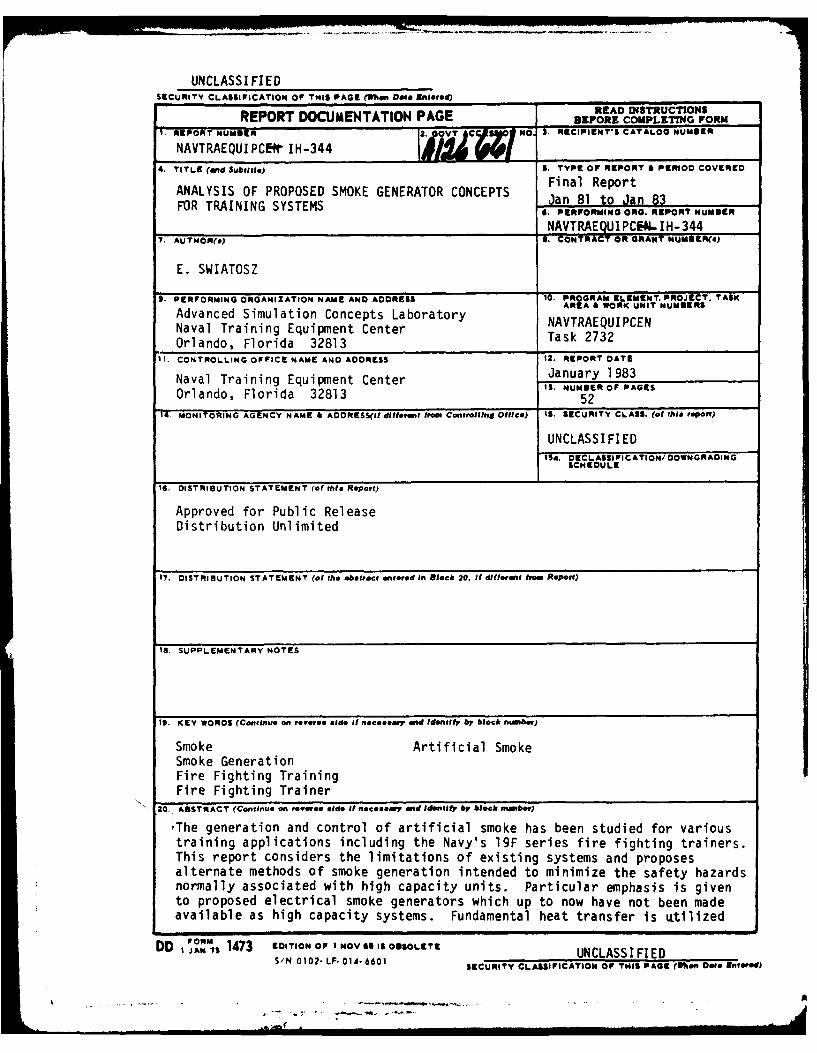
The generation and control of artificial smoke has been studied for varioustraining applications including the Navy's 19F series fire fighting trainers.This report considers the limitations of existing systems and proposesalternate methods of smoke generation intended to minimize the safety hazardsnormally associated with high capacity units. Particular emphasis is givento proposed electrical smoke generators which up to now have not been madeavailable as high capacity systems. Fundamental heat transfer is utilized
DD I 1473 EDITION OF I NOV 415 OBSOLETE UNCLASSI FIEDS/N 0 102. LF01A-6601 SECURITY CLASSIFICATION OF THIS PAGE (Whn Ost. Entered)
i Il ii i l I i i l Il l .. .... n .. . . -

UNCLASS I Fl EDECUNTY CLASSICATIQU OF T141 P&G, (ltQ0 D#l RmWOO
20. Continued
to identify the efficiency of nucleate boilinq phenomena in conjunction withnew techniques for a high capacity electrical resistance-tube technique.Other techniques include small commercial off-the-shelf electric boilers andspecial flow/atomizing nozzles. Training and simulation applicationsutilizing these techniques are suggested for further research and developmentefforts. These applications include: shore based fire fighting training;on-board ship fire drills; extinguishment agent simulation; and otherapplications such as cockpit or evacuation trainers.,
S N 0102- LF. 01-6601
UNCLASSI F EDI CUN ITY CLASSi FrCAT ON O P
r lN ll pIA O r wn D tao 3'i'e Et)
....... .. .
10 's I I • - I IIr i ii 1, .iii!..

NAVTRAEOUIPCEN IH-344
TABLE OF CONTENTS
Section Page
I INTRODUCTION ........... .......................... I
Background and Purpose ...... .. ..................... 1
Limitations of Existing Smoke Generators ..... ............ 2
II STATEMENT OF THE PROBLEM ...... .. .................... 4
Alternate Approaches ...... ... ...................... 4
Thermal Analysis ...... .... ........................ 4
Application ..... ...... .......................... 4
III METHOD OF APPROACH ...... .... ....................... 5
General ...... .... ................................
Visual Range Parameters ...... ...................... 5
Heat Transfer Relations ...... ... .................... 7
Proposed Approaches ..... .. ...................... ... 11
IV RESULTS ..... ..... ............................ . 14
Design Characteristics ...... ...................... . 14
Test Results ...... ..... .......................... 17
V DISCUSSION ......... ........................... ... 22
Boiling Heat Transfer Criteria ....... ................. 22
Residence Time/Decomposition ..... .................. ... 24
Non-Flammable Smoke Agent ...... ................... .25
Experimental Nozzle Approach ..... .................. ... 26
Limitations of the Analysis ...... .. .................. 27
Proposed Applications ..... .... ..................... 28
VI CONCLUSIONS ..... ...... .......................... 29
VII RECOMMENDATIONS ..... .... ........................ .. 30
REFERENCES ...... ... ........................... ... 31
APPENDIX A (Smoke Agent Considerations) ..... ............ 33
APPENDIX B (Boiling Heat Transfer Characteristics) .......... 37
APPENDIX C (Proposed Application of New Smoke
Generation Techniques) ....... ................... .41
GLOSSARY ...... ...... ............................ 49
Ii

NAVTRAEQUIPCEN IH-344
LIST OF ILLUSTRATIONS
Figure Page
1. Critical Maximum and Minimum Heat Flux for Boiling Heat Transfer 10
2. Proposed Smoke Generator Approach (4KW Steamaster Boiler) ... ...... 13
3. Tube Sizes for Resistance-Tube Heating .... ............... .. 15
4. Schematic Battery Operated Smoke Generator ...... ............. 16
5. Power Dissipation Battery Operated Smoke Generator .... ......... 18
6. Tubular Coil Smoke Generator Test ..... .................. ... 18
7. Boiler Smoke Generation Using Propylene Glycol ..... ........... 19
8. Fogging Characteristics for Propylene Glycol/Water Mixtures ........ 21
B-i Typical Pool Boiling Curve ......... ..................... 39
B-2 Flow Boiling Regimes ........ ........................ ... 39
C-I Portable Smoke Generator Concepts for On-Board Ship Fire
Fighting Drills ......... .......................... .. 43
C-2 Resistance-Tube Heater/Nozzle Smoke Generator Concept ........... 44
C-3 Oil-Water Interface/Nozzle Smoke Generator Concept ........... 4
C-4 PKP Extinguisher Simulation Concept ..... ................. .. 47
LIST OF TABLES
Table Page
1. Heat Transfer for 100 Feet of 114" O.D. X .015" Wall Tubing ........ 16
2. Particle Sizes for Propylene Glycol - Water Mixture
Fog Generator ......... ........................... ... 20
A-i Physical and Chemical Properties of Smoke Agent Materials
for Training Applications. ...... .................... ... 34
ii

NAVTRAEQUIPCEN IH-344
SECTION I
INTRODUCT ION
Background and Purpose
For the past several years, there has been considerable interest in the
generation and control of artificial smoke for the Navy's proposed 19F series
fire fighter trainers.1'2 Resulting studies revealed relatively few
available smoke generating systems and only one system considered acceptable
for the fire fighting trainer environment.3
The available methods for producing smoke generally involve the heating of
the smoke agent material. In these cases, various heat transfer mechanismsare involved which can significantly affect the performance of the smoke
generating unit. For example, available electrically powered smoke
generators, as presently designed, are severely limited due to the high
thermal resistance of 'he heating system. For this reason commercial high
capacity electric smoke generators as yet have not been made available.
Hence, high heat sources such as gas burners and jet pulse engines are
generally used for this purpose. However, these high temperature systems
present inherent potential hazards such as possible toxic decomposition
products as well as danger due to fire.
1. Swiatosz, Edmund, et al, New Developments in Navy Fire Fighter Trainers,Naval Training Equipment Center IH-316, Proceedings of the firstNAVTRAEQU IPCEN Interservice/Industry Training Equipment Conference,November 1979, p. 217-227.
?. Swiatosz, E.; Grimmer, P.; NAVTRAEQUIPCEN Technical Report IH-303,Experimental Research for Advanced Firefighting Simulators, May 1978,p. 45-47, 10?-10b4.
3. Fire Fighter Trainer Environmental Considerations Phase II, Booz, Allenand Hamilton, Inc., Contract N61339-79-C-O011, Mod. No. PO007, 31 July 1981.
. . . m l I I I I l N . . . .. 1-

NAVTRAEQUIPCEN IH-344
This report considers the limitations of existing systems and proposes
alternate methods of smoke generation intended to minimize the safety hazards
normally associated with high capacity units. Particular emphasis is given to
proposed electrically heated methods and boiling heat transfer analysis.
Hence, the utilization of the nucleate boiling phenomena in conjunction with
new techniques for potential high capacity are investigated. These techniques
include: low electrical resistance-tubes as a source of distributed heat;
small commercial, off-the-shelf electric boilers, and special divergent flow
atomizing nozzles. Training and simulation applications utilizing these
techniques are sungested for further research and development efforts.
Limitations of Existing Smoke Generators
The usual means of generating smoke is to vaporize an appropriate liquid
smoke agent material for subsequent condensation into smoke particulates.
Chemical or pyrotechnic methods are also used, particularly by the military,
but these are not considered safe or cost effective for enclosed training
applications.4 Another method not as common utilizes an atomizing nozzle to
shear the smoke agent liquid into ultra-fine particulates. In the first case
(vaporization/condensation), high smoke capacities are available using heat
sources such as gas burners 5 or jet pulse engines. 6 However, these
systems can also have high temperature pyrolysis effects if they are not
adequately designed or properly adjusted during operation. Hence, the
pyrolysis or decomposition will depend on the residence heating time and on
the properties of the smoke agent material.
In general, the application requirement will determine the choice of smoke
agent material and the method of smoke qeneration. Simulators such as
4. See page 102 of Reference 2.
5. See page 61 of Reference 3.
6. Operators and Organizational Maintenance Manual: Generator, Smoke,mechanical, pulse Jet, M3A3 (NSN 1040-587-3618), 12 December 1975.
2
NAVTRAEQUIPCEN IH-344
aircraft evacuation or cockpit trainers require a non-toxic and non-residue
material such as propylene glycol. On the other hand, a more persistent smoke
such as non-toxic and water soluble polyethylene glycol 200 (PEG 200) would
probably be more suitable for some on-board ship fire drills. 7 In the case
of the recently completed Navy prototype device 19F1 Advanced Fire Fighter
Trainer, the enclosed flame environment dictated the need for combined
non-toxic and non-flammable smoke properties.8
Commercially available electric foggers are presently being used for
cockpit and aircraft evacuation trainers as well as in the entertainment field
for visual effects. These units, however, are limited in capacity due to high
heater temperature gradients and high thermal resistance. These latter
characteristics are associated with a somewhat limited heating surface area
which results in a relatively low heat flux (capacity).
The approach currently used for the device 19F1 utilizes an air/liquid
mixing nozzle to produce ultra-fine, atomized smoke particulates. A high
boiling point butylated triphenol phosphate (Chem Chex 220) material is used,
with the air heated to about 1000°F for effective operation. Additional
auxiliaries such as a gas heater, pump, and compressor are required resulting
in a somewhat expensive system. The high temperature of operation can also be
a fire hazard (i.e., smoke agent leakage at the nozzle) or cause chemical
decomposition due to misadjustment or improper system design (i.e., smoke
distribution system).
Additional limitations of existing smoke generating systems in conjunction
with smoke agent material considerations are discussed in Appendix A.
7. Crook, J. W., Acute Toxicity of Polyethylene Glycol 200 in LaboratoryAnimals. ARCFL-TR-81058, October 1981.
8. Sciascia, R. M., Advanced Fire Fighter Trainer, Device 19F1, NAVTRADEVP-1550-98.
3

NAVTRAEQUIPCEN IH-344
SECTION II
STATEMENT OF THE PROBLEM
Alternate Approaches
Alternate approaches to existing smoke generating systems are to be
investigated and presented. These approaches will require consideration of
the smoke generating constraints and limitations including the objections of
low capacity electric smoke generators. These approaches will also require
analysis of heat dissipation surface areas, reduction of thermal resistance
for increasing smoke generating capacity, and utilization of boiling heat
transfer. Approaches involving "bulk heating" or long "residence time" of
contact with heated surfaces will require consideration of decomposition
effects due to smoke agent material stability and catalytic effects of metal
surfaces.
Thermal Analysis
This investigation will require a thermal analysis, including two-phase
flow along a heated tube, and consideration of the various boiling heat
transfer regimes including critical peak heat flux or "burnout" phenomena.
Application
Specific proposals for various applications usinq the alternate approaches
are to be determined. These will involve utilization of electrical
resistance-tube technique, small commercial electric boilers and special
atomizing nozzles.
4
7--- <
NAVTRAEQUIPCEN IH-344
SECTION III
METHOD OF APPROACH
General
The general approach will be to utilize an electrical powered heat source
in conjunction with an efficient thermal process involving either of two basic
smoke generating methods: vaporization/condensation; and control of smoke
agent viscosity for atomization within a special nozzle. These will require
consideration of smoke generator parameters associated with obscuration fe.g.,
visual range), operational requirements (e.g., frequency and duration .be)
and heat transfer analysis of proposed techniques for heater design.
parameters also determine material usage and flow rates for nucleate bc ng
heat transfer computations as described later in this section. The ty,
heat transfer considered (i.e., pool boiling, free or forced convection
boiling) involve various regimes which may include a two-phase flow
condition. This involves the determination of a heat transfer film
coefficient, h, which can be related to the heat flux, q/A, and the heater
surface temperature. These relationships can then be used to determine a
smoke generator design compatible with flow capacity and electrical power
requirements.
Visual Range Parameters
The smoke agent usage or flow rate will depend on the concentration,
volume, and other visual range parameters. The presence of particles in the
air results in a reduction of visual range depending on the particle size, the
number of particles, and the properties of the material. These effects on
visual range for a homogeneous aerosol of spherical particles of unit density9is given by Davies as:
MV = 5.2r (1)E
9. Davies, C. N., Visual Range and Size of Atmospheric Particles, J. Aerosol
Science, p. 335-347, Vol. 6, 1975.
5

NAVTRAEQUIPCEN IH-344
where M is the smoke concentration in g/m, V is the visual range in meters (m)
and r is the particle radius in microns (Mm). The extinction efficiency E is
a measure of the loss of light along the direction of illumination due to
scattering and absorption. The extinction coefficient can be determined by
theory (e.g., Mie's theory)1 0 or by measurement with a narrow angle device
to obtain an exponential decrease in beam intensity in accordance with the
Bouger Law (also known later as the Lambert-Beer Law).
I = Toe- ax (2)
where I/Io is the transmittance and
N 7r r 2 E (3)
where N is the Number of particles, and a and E depend on particle radius r,
the wave length of light X and the refractive index n of the particle.
As indicated in previously mentioned references, 11 for transparent
particles the value of E tends to increase to a maximum when the optical
parameter:
Ztrr 2X ~ (n1) (4)A' (n-I
With further increases in o, the value of E decreases while oscillating,
and becomes almost constant at 2 for a > 100. (See Reference 11.) As a
consequence, most effective smoke occurs when the particle radius is less than
a micron. Hence, the average particle size in conjunction with equation (1)
will determine the effectiveness of the smoke generator process, particularly
in relation to its thermal performance.
10. Green, H. L., Lane, W. R., Particulate Clouds: Dusts, Smokes and Mists,2nd Edition, p. 108, London, E F.N. Spon LTD, 1964.
11. See page 337 of Reference 9.
6
NAVTRAEQUIPCEN IH-344
Heat Transfer Relations
The boiling heat transfer 12 ' 13, 14 phenomena to be considered for the
smoke generator approaches are described in Appendix B. These are classified
into two general types of boiling heat transfer: Pool Boiling (free
convection) such as with the proposed electric boiler; and Flow Boiling
(forced convection) which is associated with the proposed resistance-tube
approach. As indicated in Appendix B, the various boiling regimes will depend
on the type and mode of operation of a specific smoke generator. A simplified
approach for determination of the heat transfer is to sum the convective
effect, either forced or natural convection without boiling, and the boiling
effect. (See Glossary pp. 33-35 for definition of terms.)
qTotal = qb + qc (5)
This approach would apply conventional heat transfer equations with
equation (5) to investigate the tubular-resistance heating approach as follows:
For regimes a, b and c in Figure B-2 of Appendix B
A Total = Aib +1c
where:
qIc (Ts - Tb) (7)
12. Kreith, F. Principles of Heat Transfer, 2nd Edition, InternationalTextbook Company, 1968.
13. Pitts, D. R., Leighton, E. S., Schaums Outline Series, Theory and Problemsof Heat Transfer, McGraw-Hill Book Company, 1977.
14. Handbook of Heat Transfer, Edited by: Rohsenow, W. M., Hartnett, J. P.,McGraw-Hill Book Company, 1973.
7
* -r , - .. ,&,,.,.I

NAVTRAEQUIPCEN IH-344
and h is given by the appropriate convection relations.15
For boiling without convection , a commonly accepted general correlation
is Rohsenow's equation for nucleate boiling 16 as follows:
hL Mhf g(P1 - Pv [cl (TS - Tsat)fj 3 (8)
For regimes d, e, g for the transition to vapor and vapor flow the
conventional gas heat transfer expression is used as follows:
qf . 3f a Tf (9)
where hf for turbulent gas flow is obtained from the Nusselt17
rel ationshi p:
Nut) h0 = (.023) Re0' 8Pr/ 13 b 14 (10)k -S)
where:
Re s VDP (11)
Pr CPA (12)
15. See page 206 of Reference 13.
16. See page 217 of Reference 13.
17. See page 170 of Reference 13.
, , i8
, ,, , il i I I II I i l i l l l

NAVTRAEQUIPCEN IH-344
The above relations can be used to estimate the approximate surface
temperatures of the heater tube for various smoke generating capacities. In
addition, however, where a superheated vapor phase is required, the critical
heat flux and the minimum heat flux conditions must be considered.
Maximum heat flux (nucleate pool boiling) relationship by Rohsenow and
Griffith1I is:
qj 143 ph- (13)X max f(
Normally, heating systems would be designed to avoid the critical heat
flux. However, where superheated vapors are required for smoke generation,
the minimum heat transfer, as indicated in Figure 1, during transition from
nucleate boiling to the gaseous phase must be considered. Expressions for
minimum heat flux and the temperature at minimum heat flux in film boiling
have been developed1 9 and are given by the following equations.
_____ [(P 1P-/ 1/4- 2i .09 P vf hfg [g(I P) 1 g0 (14)
amn 0.127Pvf [g(p - pv) 1 2/3 r go / ~ 1 /[Ti = ~ 't~ 1/2 f v1/3T (15)
18. See page 451 of Reference 12.
19. See pages 13-65 of Reference 14.
9

NAVTRAEQUIPCEN IH-344
STABLEPURE NUCLEATE FILM
CONVECTION BOILING TRANSITION BOILING
(q/A)max
HEAT FLUX
(q/A) min
//
EXCESS TEMPERATURE A T
%QUALITY (FLOW BOILING)
Figure 1. Critical Maximum and Minimum Heat Flux for Boiling.
For the case utilizing "pool boiling" for smoke generation (e.g., modified
steam boiler), the nucleate boiling equation (8) could be superimposed with
the natural convection equations involving the Nusselt number: 20
NuD hc = 0.53 (GrDPr) 1/4 (16)
f
GrD - g$( Ts -To)D
where: Z T (17)
is Grashof's number, 21 and Pr is defined by equation (12).
20. See page 206 of Reference 13.
21. See page 196 of Reference 13.
10
i t

NAVTRAEOUIPCEN IH-344
The equations (13), (14) and (15) for critical and minimum heat flux would
also apply for "pool boiling" applications.
Proposed Approaches
1. Resistance-tube. This method would utilize a long thin walled tube
as a combined electrical heating element, heat exchanger surface area and
fluid flow conduit. The tube could be coiled into a compact design for either
a steady-state or transient operations. In the first case, as shown in
Figure C-2, a small pump and reservoir system would provide the flow of smoke
agent through the tube. The dissipated electrical power, which is distributed
along the tube, is absorbed in accordance with the "flow boiling" heat
transfer described in the previous subsection. For the transient short term
operation (see Figures 4, 5 and C-4), the tube serves to store the smoke
agent. In this case, the various regimes of "pool boiling" occur sequentially
with respect to time. If heating is extended beyond the maximum and minimum
heat flux (see Figure 1, Appendix B), then the final regime is film boiling
into superheated vapor. This is subsequently released into the air where it
condenses into smoke particulates to produce the obscuration effect in
accordance with equation (2).
The resistance-tube design lengt will depend on the tube material
resistivity ( Pe ), the tube cross section (Ac) and the power requirements
(P). The power requirements are a function of the temperature limitations as
determined by the heat transfer relations. Hence, tube size can be calculated
by the following:
I P _qE AsE
R -P (19)
RL R-O
re
re a P. (21)
11

NAVTRAEQUIPCEN IH-344
Practical considerations require that an alloy material be selected to
provide a high ( Pe/L) ratio for a compact design, and for selecting the
voltage (E) within the limitations of the available current (I).
2. Commercial boiler. Various approaches are possible using a small
electric boiler,2 2 as shown in Figure 2 for a smoke generating system. For
example, a 4KW unit could be used for a "pool boiling" mode of operation to
produce superheated vapors for flow through a valve and subsequent
condensation into smoke particulates. However, this approach will require
careful consideration of the pressure/temperature characteristics of the smoke
agent material as well as consideration of heating stability of the smoke
agent material for decomposition effects. Also, boiler and heater surface
materials would have to be selected to minimize catalytic action with the
smoke agent material. A second approach to avoid these problems is to lower
the temperature sufficient for appropriate fluid viscosity for operation with
an atomizing nozzle.2 3 These nozzles would provide for mixing with injected
air (or steam) in which a shearing process takes place to produce ultra-fine
smoke particulates. Since superheated steam can be used in lieu of air, this
suggests the possibility of using the boiler for both heating a smoke agent
material and providing steam. In this case, the special properties of a
particular smoke agent material such as butylated triphenol phosphate (Chem
Chex 220) would be utilized. Thus, its high boiling point and high density
would provide a means for interface heating of an upper layer of superheated
steam for mixing with the heated smoke agent material in an atomizing nozzle.
22. Steamaster Model No. HPJ-3, Steamaster, Inc., New York, New York.
23. Fluid Kinetics Inc., Fairfield, Ohio.
12

NAVTRAEQUIPCEN IH-344
Figure 2. Proposed Boiler Smoke Generator Approach(4 KW Steamaster Boiler Apparatus)
13

NAVTRAEQUIPCEN IH-344
SECTION IV
RESULTS
Design Characteristics
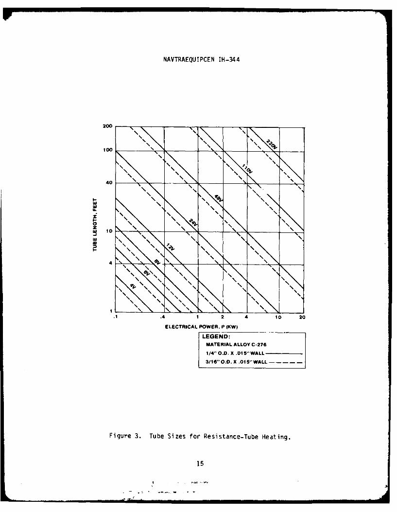
1. Resistance-tube sizing. Utilizing equations (18) through (21) in
Section III, the required tube lengths are determined as indicated in
Figure 3. These are shown as a function of the power P, tube diameter and
wall thickness for a specified alloy material. The corresponding flow
capacity through the tube will depend on the extent of heating required of the
fluid agent. For boiling beyond the transition regime and accounting for
latent heat of vaporization, smoke generation of propylene glycol would be on
the order of 1.0 gph/KW. As indicated in Figure 3, the tube length and
capacity (KW) range from a practical minimum 30" length for a 4V system at
.2 gph (test results indicated later in this section) to about a 100 foot
length for a higher capacity system considered appropriate for training
applications (i.e., fire fighting training). In general, as the voltage and
tube length are reduced for a constant capacity (KW), the tube temperatures
will increase. The design temperature limit will then be dependent on the
fluid flow through the tube and the heat transfer relations discussed in
Section I1.
2. Heat transfer/resistance-tube. The temperature differential AT and
the maximum and minimum heat flux were calculated utilizing equations (5)
through (17) as indicated in Table 1 for 100 feet of 1/4" x .015" wall
material C-276 alloy tubing for propylene glycol smoke agent.
14
NAVTRAEQUIPCEN IH-344
200
100 't
40 10
U.
-li
441 2 4 0 2
ELECTRICAL POWER, P (K(W)
LEGEND:MATERIAL ALLOY C-276
1/4" O.D. X .015"WALL
3/16 O.0. X .015'*WALL-- -----
Figure 3. Tube Sizes for Resistance-Tube Heating.
15

NAVTRAEQUIPCEN IH-344
HIGH CAPACITY RECHARGEABLEFILL PLUG BATTERIES (30-50 AMP, 4-6V)
ORIFICE ._ _ _.
TUBULAR COIL ELECTRONIC SWITCH
HIGH CURRENT CONDUCTOR ARMINGLARGE HEAT TRANSFER AREA AUTO. SHUT-OFFCONTAINER FOR SMOKE AGENT
Figure 4. Schematic Battery Operated Smoke Generator.
TABLE 1. HEAT TRANSFER FOR 100 FEET OF 1/4" O.D. X .015" WALL TUBE
REGIME G (q/As) AT (q/A)max (q/k)min(SeeAppendix B gph Btu/hr- OF Btu/hr- Btu/hr-
Figure B-I) ft2 - OF ft2 - OF ft? - OF
a, b, c 2.5 1800 43 458,000
eq. (7), 5.0 3600 57 458,000
(8), (13) 10.0 7200 75 458,000
d, e, f 2.5 1800 29 - 34,000
eq. (10), (14) 5.0 3600 17 34,000
10.0 7200 10 34,000
16
! -- -.. .m'" .. . .I I Ill
NAVTRAEQUIPCEN IH-344
Test Results
1. Tubular resistance coil. An experimental model shown schematically
in Figure 4 was used to demonstrate feasibility. Three high capacity lead
acid batteries, each two volt and five ampere-hour, were connected across the
tube (3/16" O.D. X .015" Wall X 30" Long) containing 0.3 cubic inches of
propylene glycol. About a one-minute power dissipation, as shown in Figure 5,
was required to evaporate the material and rupture the fusible disc. Smoke
was produced from the superheated vapor as indicated in Figure 6 for a period
of about 12 seconds. The operation was repeated 15 times with batteries
recharged each time and with consistently similar results. A similar test
using PEG 200 material was conducted with a more persistent smoke result.
2. Commercial steam boiler. These tests utilized an off-the-shelf 4 KW
electric boiler2 4 with propylene glycol heated to a 420°F temperature and
40 psig pressure. Initial operation provided a transient smoke at about 30 to
50 gph rate for about 15 seconds, through a 1/4 inch diameter discharge tube.
Subsequent tests as shown in Figure 7 utilized a .060 orifice to produce about
a 3 gph smoke having about a 1.5 micron (pm) average particle size. Rapid
discoloration of the heated propylene glycol liquid occurred in the boiler
tank almost immediately during the first heating period. This was due to the
catalytic action of the copper clad heating elements and the carbon steel
boiler tank on the heated propylene glycol.
3. Modified steam boiler. The steam boiler in Item 2 above was reworked
and modified by nickel plating both the interior carbon steel boiler and the
heating elements. Also, the carbon steel fittings and piping were replaced
with stainless steel. Propylene glycol was heated to 420°F at 40 psig
pressure and maintained for eight hours per day for three consecutive days.
No discoloration was apparent the first day. Slight discoloration was noted
the second day and a thin layer of black decomposition products accrued at the
bottom of the boiler after the third day.
24. See Reference 22.
17

NAVTRAEQUIPCEN IH-344
200
0 X 40 AMPS.P
a
~START OFfSMOKE GENERATION
020 40 60 so 10O0 120
TIME, SECONDS
Figure 5. Power Dissipation Battery Operated Smoke Generator.
Figure 6. Tubular Coil Smoke Generator Test.
18

NAVTRAEQUIPCEN IH-344
Figure 7. Boiler Smoke Generator Using Propylene Glycol.
4. Propylene qlycol/water mixtures. Measurements of visual ranqe for
various propylene glycol/water mixtures were made using the steam boiler
(Figure 7). Test results showing visual range as a function of time, and
decreasing flow rate as a function of increasing water content are shown in
Figure 8. The correspondinq increase in particle size with increasinq water
content was calculated using equation (2) as shown in Table 2.
19

NAVTRAEQUIPCEN IH-344
TABLE 2. PARTICLE SIZES FOR PROPYLENE GLYCOL/WATER MIXTURE FOG GENERATOR
Test Run Percent Water Average particleNo. (Average) diameter,( pm)
1 44 7.3
2 34 4.9
3 26 3.6
4 11 2.6
5 0 1.5
20

NAVTRAEQUIPCEN IH-344
16
14 VAPOR PRESS- 42-47 PSIG
CHAMBER SIZE- 1340 CU. FT.FLOW NOZZLE- .06 IN. DIA.
12TEST WATER FLOWRUN CONTENT RATE
NO. %(AVG) GPH(AVG)
S10 0 4 .
(D 34 1.1
0 (D 6.8
(3 2 11 2.7
c. 0 3.0
6 0
3
4 '
, \"
I I
2
0
0 2 3 4 5
TIME, MINUTES
Figure 8. Fogging Characteristics for Propylene Glycol/Water Mixtures.
21
NAVTRAEQUIPCEN IH-344
SECTION V
DISCUSSION
Boiling Heat Transfer Criteria
A somewhat simplified heat transfer approach was formulated in Section III
from complex boiling theory to determine:
o The potential feasibility of a high capacity electric smoke generator
(which to date has not been accomplished by industry).
o The reduction of high temperatures normally associated with high
capacity smoke generators.
o The following rationale for the proposed smoke generator approach:
a. Flow boiling/resistance-tube. The basis for this approach are
the maximum and minimum heat flux indicated by Figure I and the various
regimes described in Appendix B and by the heat transfer equations in SectionIII. These indicate limitations of the critical peak heat flux, (q/A)max, for
conditions when nucleate boiling dominate the heat transfer before
vaporization (mist flow regime) take place. Normally the critical transition
boiling regime is avoided to prevent possible "burnout." This could occur in
some systems when the heat transfer coefficient is suddenly reduced to the
(q/A)min condition. In the case of an atomizing fogger nozzle, nucleate
boiling would be useful as an efficient method to reduce fluid viscosity (and
resistance to shear) as a method to produce smoke particulates. However,
since the vaporization/condensation approach includes all the regimes of flow
boiling, then flow capacity is limited by the minimum heat flux equation (14).
22

NAVTRAEQUIPCEN IH-344
The values of minimum and maximum heat flux and the temperature
differential, AT, for the corresponding flow capacities are given in Table 2.
These indicate a relatively high flow rate for vaporizing propylene glycol
within the minimum flux, (q/A)min, which would be more than appropriate for
most training smoke applications.
The calculated lot% temperature differentials AT, shown in Table 2
indicates the effectiveness of the resistance-tube technique. This is the
result of distribution of 12R power over a wide area, and the use of this
area as a heat transfer surface to a relatively small amount of smoke agent
material. Thus a low thermal resistance is provided in a radial direction
resulting in a low thermal gradient (AT). Hence, the resistance-tube
technique tends to match the high thermal efficiency associated with the flow
boiling regime.
The critical peak heat flux, as well as the minimum heat flux, are
independent of the heating element (e.g., depends on the smoke agent material
properties and the type of metal surface). Therefore, the resistance-tube
dimensions can be determined in accordance with parameters of Figure 3 to
match the limitations of the minimum heat flux.
b. Pool boiling. The 4KW commercial steam boiler used for tests
with propylene glycol, was limited by its relatively small heating surface
area. Hence, the heat flux was about 18 watts/cm 2 for the boiler heater
compared to about 1.5 watts/cm 2 for the same total ouput of the
resistance-tube approach. This puts the heating range in approximately the
same level as the minimum heat flux, (q/A)min, for propylene glycol with the
commercial boiler. However, the 18 watts/cm 2 boiler heat flux is within the
critical heat flux indicated in Table 1, therefore excess temperature burnout
would not be expected.
23
5i4

NAVTRAEQUIPCEN IH-344
The decomposition of propylene glycol noted in the long term heating tests
was drastically reduced when the copper heater surfaces and carbon steel
boiler materials were nickel cladded. This identified the catalytic action of
the former materials as a primary cause of decomposition of the heated
propylene glycol. However, although (q/A)min was exceeded by a large factor,
it would appear that a duty cycle type of operation utilizing the bulk heat
storage of the boiler would be feasible. That is, a low level heating of the
smoke agent (less than 1 KW) for long periods and short intermittent smoke
usage at high capacity (4 KW).
The commercial boilers may be better suited in heating applications with
an atomizing nozzle smoke generator. Hence, it can be operated in the
nucleate boiling regime without exceeding the peak heat flux, (q/A)max. The
resistance tube, on the other hand, can provide a distributed source of 12R
heating over a large area with a relatively small material contained in the
tube. Then vaporization of propylene glycol in the stable film boiling regime
would be possible without exceeding the minimum heat flux, (q/A)min, thereby
providing higher capacity.
Residence Time/Decomposition
An important consideration is the "residence time" of heating. Smoke
agent materials can decompose at high temperatures but this depends on the
stability of the material and the time duration the smoke agent is in contact
with a heated surface. In some cases this may be a matter of milliseconds.
For example, if a smoke agent is injected into a hot gas stream or against a
heated surface, vaporization may take place rapidly and tend to cool the
heating medium quickly. If excess heat and temperature are applied then
decomposition may take place. In the case of the relatively long
resistance-tube, prolonged heating may vary from a fraction of a minute or
longer. However, in this case the heating surface will be at a relatively low
level due to its low thermal resistance characteristics. Also, the
significant residence time will be a fraction of the total residence time
since the temperature is near or beyond the boiling point will comprise of a
24
I,

NAVTRAEQUIPCEN IH-344
partial section of the resistance tube. Since the resistance-tube tests of
Section IV (Figure 6) were within the minimum heat flux (q/A)min, this would
explain the lack of decomposition residue after numerous operations.
The bulk heating with a commercial boiler approach will have a long
duration heating of smoke agent material. The test results of Section IV withpropylene glycol still indicated decomposition (although drastically reduced)
after the catalytic effects for material surfaces were substituted. In this
test, decomposition seems to occur after a relatively long period of time, butits final cause has not been determined (e.g., cyclinq of heater operation, or
minimal catalytic effects). Hence, further testing for decomposition for this
approach would still be required.
Non-Flammable Smoke Agent
As indicated in Appendix A, a non-flammable smoke is a desirable
constraint. Although smoke concentrations for extreme obscurations (lowvisual ranges) are generally a small percentage of the lower explosive limit,
a reportedly non-explosive smoke agent (butylated triphenol phosphate) wasselected for the Navy's Device 19F1 25 fire fighter trainer. However, as
noted in Section I and Appendix A, a high temperature system is required.
This can cause problems of autoignition if a pressure leak occurs and a smoke
agent liquid impinages on a hot surface in the open air and bursts into
flame. A problem can also occur if the smoke distribution piping is
maintained at high temperatures where the high concentrations of smoke
particulates may be susceptable to decomposition.
25. See page 134 and Appendixes of Reference 3.
25
NAVTRAEQUIPCEN IH-344
Another possible non-explosive smoke agent considered was a mixture of
propylene glycol and water. Results on testing this mixture for explosiveness
in an oxygen atmosphere have been reported.26 The fire protection code also
lists a 30 to 60 percent propylene glycol and water mixture for non-freezing
sprinkler systems for fire protection.27 The limited test data on propylene
glycol/water fog generation shown in Figure 8 indicate the feasibility of
effective obscuration for this approach. The advantages would be an
application where a non-residue and non-explosive smoke is warranted. Further
testing would be required to determine mixture ranges for non-flammability and
decomposition limits, particularly where hot surfaces and possible oncogenic
effects are involved.
Experimental Nozzle Approach
Fluid particulates can be produced by three general types of atomizing
nozzles. In order of decreasing particle size, these are: (a) liquid spray
into ambient air, (b) air-atomizing by impact of a stream of gas or air, and
(c) a sonic flow nozzle which mixes liquid and gas in a divergent expansion
chamber internal to the nozzle. The sonic flow nozzle produces a water
particle sizes spectrum to less than a few microns. Particle sizes down to
0.5 micron have been reported for some fuel atomization applications.28
Smaller particle size generally result from: increases in air liquid
pressure; smaller orifice-size; more dense liquid; less viscous liquid; and
lower surface tension.
26. Jamison, H. H., Determination of Water-Glycol, Coolant Flammability, NASA,June 1967.
27. National Fire Protection Association, National Fire Codes, Volume One,1975, pages 13-94.
28. See Reference 23.
26

NAVTRAEQUIPCEN IH-344
The proposed atomizing nozzle approach will require experimental testing
to detemine performance of particle size distribution for various smoke agent
materials and heating conditions. This would include heating of the liquid
material to facilitate the shearing process within the nozzle. In this report
the oil-water interface/nozzle smoke generator described in Section III
(Figure 2b) would be a viable approach. Further study and experiments are
planned using this approach due to its simplicity of control, low temperature
and potential low cost. The resistance-tube approach is also a viable method
but would require an auxiliary air supply (plant air). However, heating would
be well within the (q/A)max limit discussed previously. Consideration for
utilizing the heating element as a temperature controller for this
application appears to be appropriate.
Limitations of the Analysis
The various technologies involved in smoke generation are extensive.
These include physical and chemical behavior of materials under various phase
conditions, in addition to the emphasis given to heat transfer in this
report. A somewhat simplified approach was used for the heat transfer
analysis along with a limited amount of testing sufficient only for
preliminary investigation. This approach was necessary due to the complexity
of the boiling phenomena which involves a large number of variables.
Extensive testing for determining empirical relationships were considered
beyond the scope of this report.
It is probable that better use could be made of the considerable progress
that has been made in the past few years in gaining a physical understanding
of the boiling mechanism. However, neither general equations describing the
process nor general correlations of boiling heat transfer data are available
to date.
29. Series ADG Temperature Controllers, Reference 23.
27
, ii , , - , , , , , , I I I I I I Ill Im I I II II I
NAVTRAEQUIPCEN IH-344
The proposed mechanism for the various two-phase flow or pool boiling
regimes are useful but must be treated with caution. These are generally
empirical equations obtained under specific conditions which may not be
applicable to other configurations and fluids.
Other limitations are the determination of chemical decomposition effects
of the combination of high temperature, catalytic action of the various
materials and residence time of heating. This also would require empirical
type testing involving a specific smoke generator application.
Most of the heat transfer analysis and tests were essentially limited to
propylene glycol material. This is because propylene glycol was initially
selected as the most probable candidate for training applications. Although
this was sufficient for the scope of this investigation for the proposed smoke
generating techniques, further research is required for demonstrating
feasibility of these techniques with other materials including butylated
triphenol phosphate and polyethylene glycol 200 (PEG 200).
Proposed Applications
Various types of applications of the proposed smoke generators utilizing
resistance-tube and commercial boiler approach are suggested in Appendix C.
These applications include: shore based fire fighting training; on-board ship
fire drills; extinguishment agent simulation; and other applications such as
cockpit or aircraft evacuation trainers.
The choice of smoke agent material for these applications is dependent on
the restraint factors indicated previously in Section I and in Appendix A,
such as flammability and residue. However, the choice of a smoke generator
approach (i.e., vaporization or atomizing nozzle) will also depend on the type
of smoke agent material.
28

NAVTRAEOUIPCEN IH-344
SECTION VI
CONCLUSIONS
The fundamental heat transfer analysis identifies the efficiency of the
boiling thermal process and the heat flux distribution advantages of the
electrical resistance-tube smoke generation technique.
These advantages include comparatively low temperature operation to
minimize or eliminate decomposition or fire hazards associated with existing
high heat source units.
In effect, this approach indicates a potential for a high capacity
electric smoke generator which up to now has not been available.
The resistance-tube technique can be operated in the mist-flow regime
below the minimum heat flux limit, whereas a commercial electric boiler may be
limited to the nucleate boiling regime: i.e., critical peak heat flux for
propylene glycol.
Various proposed systems utilizing atomizing or fogger nozzles are
available that have not been fully explored for smoke generating systems.
This includes an electric boiler technique which would utilize the unique
properties of butylated triphenol phosphate (Chem Chex 220) which is presently
used in the Navy's device 19F1 fire fighter trainer.
Several potential applications of the proposed techniques appear to
justify further research due to inherent advantages of lower temperature,
minimal fire and decomposition hazards, and simplified design approach.
Further feasibility study and testing will be required for specific
applications of the proposed approaches.
29

NAVTRAEOUIPCEN IH-344
SECTION VII
RECOMMENDAT IONS
The following actions are recommended:
1. The feasibility of high capacity electric smoke generators should be
explored further for feasibility of practical application on the basis of
(a) need and availability of specific applications and (b) the advantages of
low temperature control for minimizing safety hazards and providing potential
cost effectiveness.
2. Specific testing should be conducted in the areas of (a) resistance-
tube technique and (b) low temperature atomizing nozzle technology.
3. After evaluation of the feasibility of the proposed approaches, a
contract effort on selected prototype models should be procured for field
testing.
30

NAVTRAEQUIPCEN IH-344
REFERENCES
Crook, J. W., Acute Toxicity of Polyethylene Glycol 200 in Laboratory Animals,
ARCFL-TR-81058, October 1981.
Davies, C. N., Visual Range and Size of Atmospheric Particles, J. Aerosol
Science, Volume 6, 1975.
Fire Fighter Trainer Environment Considerations Phase II, Booz, Allen and
Hamilton, Inc. Contract No. N61339-79-C-0011, Mod. No. P00007, 31 July 1981.
Fluid Kinetics Inc., Fairfield, Ohio.
Green, H. L., Lane, W. R.; Particulate Clouds: Dusts, Smokes and Mists,
2nd Edition, p. 108, London, E F.N. Spon LTD, 1964.
Handbook of Heat Transfer, edited by Rohsenow, W. M.; Hartnett, J. P.; McGraw-
Hill Book Company, 1973.
Jamison, H. H., Determination of Water-Glycol Coolant Flammability, NASA,
June 1967.
Kreith, F., Principles of Heat Transfer, 2nd Edition, International Textbook
Company, 1968.
National Fire Protection Association, National Fire Codes, Volume One, 1975.
Operators and Organizational Maintenance Manual: Generator, Smoke, Mechanical,
Pulse Jet, M3A3 (NSN 1040-587-3618), December 1975.
Pitts, D. R.; Leighton, E. S.; Schaums Outline Series, Theory and Problems of
Heat Transfer, McGraw-Hill Book Company, 1977.
31

NAVTRAEQUIPCEN IH-344
Sciascia, R. M.; Advanced Fire Fighter Trainer, Device 19F1, NAVTRADEV
P-1550-98, 1982.
Steamaster Inc., New York, New York.
Swiatosz, E.; Guthrie, W. N.; Cadle, H. H.; New Developments in Navy Fire
Fighter Trainers, Naval Training Equipment Center IH-316, Proceedings of the
First NAVTRAEQUIPCEN Interservice/Industry Training Equipment Conference,
November 1979, p. 217-227.
Swiatosz, E.; Grimmer, P.; NAVTRAEQUIPCEN Technical Report IH-303, Experimental
Research for Advanced Firefighting Simulators, May 1978.
32
7 n¢
NAVTRAEQUIPCEN IH-344
APPENDIX A
SMOKE AGENT CONSIDERATIONS
The smoke agent material must meet health and safety requirements for
training. In general, most smoke agents are eliminated from consideration by
rationalizing all significant characteristics. These inci.'de toxic effects,
flammability, corrosiveness, residue effects, cost and the training
environment. Recent studies considered these factors to select an appropriate
smoke from available candidates for the Device 19FI Advanced Fire Fighter
Trainer.1 These included mineral oil, propylene glycol, polyethylene qlycol
200 (PEG 200) and butylated triphenol phosphate (Chem Chex 2202). The
latter material as a smoke is reportedly a non-toxic/non-flammable form of
triaryl phosphate and was selected for the 19F1 for these reasons. However,
Chem Chex 220 in liquid form is still susceptible to burning with the flash
point, fire point and auto-ignition temperatures as indicated in Table A-i.
The Chem Chex 220 and PEG 200 smoke particulates are persistent smokes and
resistant to rapid evaporization in the high temperature environments
encountered in some fire fighter trainers. This is unlike propylene glycol
smoke which tends to evaporate rapidly when the ambient temperature reaches
140°F to 160°F. For this reason and the fact that propylene glycol will
decompose at high temperatures, it has not been recommended for the Device
19FI.3
The flammability of smokes from materials such as propylene glycol or
other hydrocarbo has been a serious consideration for the 19F1 trainer
1. Fire Fighter Trainer Considerations Phase II 9ooz, Allen and Hamilton,
Inc. Contract No. N61339-79-C-0011, Mod. No. PO0007, 31 July 1981.
2. TIFA (C.I.) Limited, Millington, New Jersey.
3. Boronson, M. L.; et al, "Propylene Glycol as a Fire Smoke Stimulant."NRL Report 8477, 29 June 1981.
33

NAVTRAEQUIPCEN IH-344
TABLE A-I. PHYSICAL AN[) CHEMICAL PROPERTIES OFSMOKE AGENT MATERIALS FOR TRAINING APPLICATIONS
PROPYLENEPEG 200 GLYCOL CHEM CHEX 220
Chemical Name Polyethylene Propylene ButylatedGlycol 200 Glycol Triphenol
Phosphate
Other Name Carbowax 200 - TriarylPhosphate
Physical State, Liquid Liquid Liquid
at 77'F, 1 atm
Specific Gravity 1.127 1.038 1.12-1.21
Viscosity 4.3 Centistokes .581 Poise 90-1000 SUSat 210°F at 20C at 100°F
Average Specific .52 .59Heat, Cal/qm/C
Vapor Pressure, <.01 .07
at 20°C, mm Hg
Boilinq Point, °C 315 188 391
Pour Point/ - (-60°C) -30' tu 30°FFreezing Point
Flash Point, °F >350 214 450
Fire Point, 'F - 650
Autoignition, °F - 790 1050
3'l

NAVTRAEOUIP(;EN IH-344
environment.4 For these materials however, the danger is somewhat minimized
considering the extreme obscuration obtained (visual range 1 to 3 feet) for
relatively low smoke concentrations which are generally less than 2 percent of
the explosive limit. It should be noted however that materials in the
invisible or transparent vapor state could add to this concentration.
However, unlike a "natural" fire which may have a large source of volatile
material to produce a dense smoke, an artificial smoke generator needs only a
limited amount of material. Since an extremely large amount of material is
generally required to produce a flammable smoke concentration, then the
control of usage rate would "nd to preclude a flammability hazard.
4. Swiatosz, E.; Grimmer, P.; NAVTRAEQUIPCEN Technical Report IH-303,Experimental Research for Advanced Firefighting Training Simulators, May 1978,p. 45-47, 102-104.
35

(This Page Blank)
36
- 7

NAVTRAEQUIPCEN IH-344
APPENDIX B
BOILING HEAT TRANSFER CHARACTERISTICS
Boiling heat transfer 1'2'3 involves vaporization (and its inverse
condensation) which is one of tjhe most common phase-change processes. A
simple expression relates the heat transfer film coefficient, h, with the heat
flux, q, to the temperature differential between the heating surface area and
the saturated smoke agent liquid as:
q = hA (Ts - T sa)
However, a phase-change process involves changes in variables (i.e.,
density, viscosity, specific heat, thermal conductivity and thermal
expansions) while the fluid's latent heat is being absorbed (vaporization).
Hence the heat transfer coefficient is much more complicated than for a
single-phased convective process and will generally require empirical
correlations in making calculations.
The behavior of a fluid during boiling involves various regimes that arehighly dependent upon the "excess temperature" AT = Ts - Tsa t* The
essential features of boiling heat transfer are the extremely high rate of
heat transfer compared with the normal convective processes and the conditions
of peak heat flux, called the "burnout point." This occurs when the bubble
columns or vapor steam is retarded by the downward replacement liquid
resulting in an increased thermal resistance vapor blanket. In some
1. Kreith, F., Principles of Heat Transfer, 2nd Edition, InternationalTextbook Company, 1968.
2. Pitts, D. R., Leighton, E. S., Schaums Outline Series, Theory and Problemsof Heat Transfer, McGraw-Hill Book Company, 1977.
3. Handbook of Heat Transfer, Edited by: Rohsenow, W. M., Hartnett, J. P.,McGraw-Hill Book Company, 1973.
37

NAVTRAEOJIPCEN IH-344
instances, the temperature at this point is above the melting point of most
heater materials, and the failure of the heater occurs before reaching it.
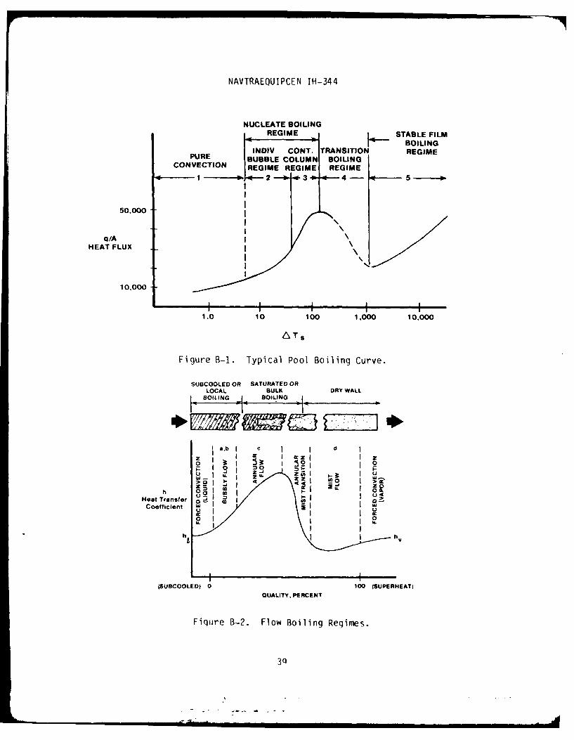
Two general types of boiling heat transfer are considered for the various
vaporization type smoke generators: Pool Boiling (free convection); and Flow
Boiling (forced convection). The various boiling regimes for these are shown
in Figures 1 and 2 respectively. Pool boiling involves the relations of five
regimes: free convection (Regime 1); nucleate boiling (Regimes 2 and 3); and
film boiling (Regimes 4 and 5). Flow boiling occurs when a liquid flows
through a tube which is maintained at a higher temperature than the saturation
of the liquid. The flow is a two-phase mixture of liquid and its vapor as
shown in Figure 2. This indicates a subcooled liquid entering a tube
(evaporator) and passing over the hotter wall where nucleate boiling occurs.
The flow is considered bubbly for 10 percent vapor quality with increases in
heat transfer coefficient. At hiqher qualities it becomes "slug-flow," then"annular" with a thin liquid layer on the wall and a vapor core, with the
velocity of the vapor much higher than the liquid. In the transition from
annular to vapor flow the heat transfer coefficient drops sharply and burnout
can sometimes occur at this point. Vapor flow continues until 100 percentquality is reached when conventional forced convection is then the mode of
heat transfer.
The point of maximum heat transfer or the critical heat flux is
independent of the heating element. If the temperature of the heating element
at this point is not excessive to cause burnout, the boiling curves of
Fiqures B-1 and [3-2 continue to rise to beyond the boiling regime. Most
applications do not go beyond the critical heat flux and use average heat flux
in designs. Since heat flux is a local quantity for a given regime in the
proposed application, then the local temperature value should be considered as
conservative for the design.
In general, the analytical expressions of the various modes and reqimes of
boiling heat transfer are quite complicated. Superposition techniques are
qenerally used and simplified approaches for the heat transfer relations in
Section III are utilized.
38
NAVTRAEQUIPCEN IH-344
NUCLEATE BOILINGREGIME SABLE FILM
INDIV CONT. TRANSITION REGIMEPURE BUBBLE COLUMN BOILINGCONVECTION REGIME REGIME REGIME
W-. No- 2---b 3 - 4-o
50.000
qIAHEAT FLUX
10,000
1.0 10 100 1,000 10,000
ALTS
Figure B-1. Typical Pool Boiling Curve.
SUBCOOLED OR SATURATED OR
LOA BULK DRY WALL
a,b cc c dzz
Neatranser -j I ICoS I U. z U. 5 M
U2U
01
h t
(SUBCOOLED? 0 100 (SUPERHEAT)QUALITY. PERCENT
Fiqure B-2. Flow Boiling Regimes.
3Q
NAVTRAEQUIPCEN IH-344
(This Page Blank)
40
NAVTRAEQUIPCEN IH-344
APPENDIX C
PROPOSED APPLICATION OF NEW SMOKE GENERATOR TECHNIQUES
The new techniques for smoke generation such as resistance-tube and
commercial boilers have yet to be fully developed and tested. The advantages
of these systems, however, indicate potential applications in the following
areas:
a. On-board ship fire fighting drills.
b. Shore-based fire fighting training.
c. Extinguishment agent simulation.
d. Other applications (such as aircraft evacuation, cockpit training,
theatrical affects).
(1) On-board ship fire fighting drills. The general purpose for
this application is a means for providing training smoke aboard a Navy vessel
for fire fighting training purposes. A requirement has been stated for a
small self-contained but inexpensive smoke cartridge that can be easily
applied for short periods of smoke generation.
The background for this application indicated that the Navy has in
the past been interested in smoke generators for fire drills. Commercial
smoke bombs or grenades are available, but these are pyrotechnic in nature and
some produce highly toxic smoke such as zinc chloride ,nd hence, cannot be
used indoors. The Army has many smoke devices but they do not fall in the
present category. The Naval Weapon Supply Center has recently studied a
pyrotechnic smoke bomb using non-toxic propylene glycol as a smoke agent.
However, their study has been discontinued since their projected development
costs per unit were estimated about $6 to 18 each.
Description and operation of a proposed portable smoke generator.
Smoke can be produced by supplying heat to a material such as oil or propylene
glycol and thus vaporizing it. The vapor is then condensed in air to produce
a cloud of small particulates to produce the smoke. One proposed method is to
41

NAVTRAEOUIPCEN IH-344
use the electric current from a small, but high capacity, battery as a source
of heat energy. A battery such as a Gates Model PNO800-004 (5 ampere-hour) or
equivalent would have a high density energy and could provide 20 to 50 amperes
for a short period of time. The battery is rechargeable and can be used many
times (200-500 for complete discharge). A relatively small amount of
propylene glycol (or carbo wax 200 for a more persistent smoke) is required,
from .5 to 3.0 cubic inches, depending on the rate or duration of smoke. The
smoke device ;s illustrated by Figure C-i.
The device is actuated by closing an arming switch which permits flow
of current through a tubular resistance coil. The coil is designed to contain
the smoke agent, carry sufficient current, and have appropriate surface area
to dissipate heat to vaporize the liquid smoke agent. When the temperature
reaches a set level above the vaporization temperature, the pressure will rise
to a point to open the relief valve (or fusible disc). The vaporized liquid
will flash through the relief valve discharge and out the control orifice to
produce the smoke. The battery can be selected so it can be expended at a
preselected time period depending on the selected resistance heating element.
The quantity of liquid and smoke generated can be preselected to match the
output of the battery. A timing device can be utilized in lieu of the arming
switch which could limit the battery operating time ano hence can be used
consecutively before recharging both the battery and the liquid smoke agent.
As an alternate, a plug-in operation for 110V outlet can be provided in lieu
of batteries. This would provide 4 to 10 times the smoke generating capacity
while still maintaining some portability, but not to the degree of a battery
system.
The advantages of this system are indicated in Figure C-1. These
indicate a low unit cost of operation as a reusable smoke generating unit as
compared with existing disposable pyrotechnic smoke bombs. Other advantages
are its safety and minimized storage requirements.
42

NAVTRAEQUIPCEN IH-344
TIMER/SWITCH
HIGHCAPACITY
RECHARGEABLEBATTERIES
LOW ELECTRICAL RESISTANCE-TUBES
LOW VOLTAGE/RESISTANCE-TUBE CONCEPT
RELIEF VALVE OUTLET TIMER/SWITCH
CORDSTORAGE
2HIGH ELECTRICAL RESISTANCE -TUBES 2 0V
(DOUBLE NESTED TUBING) J IVPLUG
HIGH VOLTAGE /RESISTANCE-TUBE CONCEPT
NEW CONCEPT NAVY CURRENTRESISTANCE- PYROTECHNIC COMMERCIAL
TUBE PROPOSAL PYROTECHNIC
TRAINING HIGH LOW LOWEFFECTIVENESS
TOXICITY NO NO YES
FIRE HAZARD NO YES YES
UNIT COST LOW HIGH HIGHPER ACTIVATION (REUSABLE) IDISPOSABLE) IDISPOSABLE)
DEVELOPMENT LOW HIGH EXISTINGCOST
COMPARISON ON-BOARD SHIP FIRE FIGHTINGTRAINING ALTERNATIVES
Figure C-i. Portable Smoke Generator ConceptFor On-Board Ship Fire Fighting Drills.
43

NAVTRAEOUIPCEN IH-344
CONTROLCONITRL AIR PRESSURE220 V./11 OV. UNIT SUPPLY
• ATOMIZING
NOZZLE
RESERVOIR FEED RESISTANCE-TUBEPUMP
Figure C-2. Resistance-tube Heater/Nozzle Smoke Generator Concept.
(2) Shore-based fire fighting training. The Device 19F1 Advanced
Fire Fighter Trainer utilizes a clean burning propane flame environment, hence
the introduction of a non-toxic training smoke would be limited to a
non-flammable material smoke such as butylated triphenol phosphate (Chem Chex
220). However, this material would generally require a high temperature smoke
generating system due to its high boiling point. Another approach is to
utilize the material in conjunction with an atomizing nozzle as described
previously in this report. This suggests the possibility of preheating the
smoke agent material prior to injecting it with pressurized air (or
superheated steam) through a special atomizing nozzle using the
resistance-tube technique as illustrated in Figure C-2.
A variation of this approach is shown in Figure C-3 which utilizes
the unique properties of Chem Chex 220. These properties are its high boiling
point (735"F) and specific gravity (1.1 to 1.2) greater than water, and the
44

NAVTRAEQUIPCEN IH-344
fact that it is not miscible with water. Hence combined heating of the two
materials in a boiler would provide both superheated steam and heated smoke
agent material for subsequent injection of both fluids into a similar type
atomizing nozzle as referenced in this report (see reference 23). This
atomizer would be designed to mix pressurized air (or steam) with heated smoke
agent fluid in a chamber within the nozzle. Air flow from this chamber at
sonic velocity would accelerate a liquid film on an annular surface. The
liquid film is thus reduced and sheared as the compressed air expands within a
divergent nozzle. Supersonic velocities are attained resulting in pressure
fluctuation and shock waves which vibrate the liquid layer causing further
shearing and break-up of the material for complete atomization. Any
significant percentage of large droplets which may be present would be
filtered out of the resulting smoke.
The advantages of this approach is that it avoids a more complicated
high temperature air heater and the possible decomposition of smoke agent
substance is minimized or eliminated.
SUPERHEATEDSTEAM
WATER
NOZZLE
Figure C-3. Oil Water Interface/Nozzle Smoke Generator.
45
NAVTRAEQUIPCEN IH-344
(3) Extinguishment agent simulation. Another application utilizinq
the resistive-tube technique is described by Figure C-4. The basic idea would
be to produce a dense cloud of smoke from a portable container to simulate the
Navy's PKP extinguisher. Optical type sensors would be required to sense the
smoke and provide a control signal for flame control (i.e., oil spray fire) or
extinguishment via valve closure. For a real fire trainer, a non-flammable
smoke such as butylated triphenol phosphate or a mixture of propylene glycol
and water may be feasible. The latter case would require extensive tests for
possible decomposition of a dense cloud in a flame environment. Evidence of
non-flammability of propylene glycol/water mixtures have been reported (see
reference 26) and is also used as a low freezing method in fire sprinkling
systems (see reference 27). The test data shown in Figure 8 on smoke
performance of waterfpropylene mixtures indicate significant increases in
material usage and particle size, both of which would greatly increase energy
requirements for vaporization. For non-fire or visual simulated fire, such as
Ansul's I fire fighting trainer, propylene glycol would provide a residue
free smoke cloud with minimal material usage.
(4) Other applications. Propylene glycol would be a prime choice
for enclosed, non-flame environment such as for cockpit or commercial aircraft
evacuation trainers where minimum or non-residue is a requirement. At
present, some of these trainers utilize a modification of inexpensive, low
capacity electric foggers. However, for higher capacity smoke generation
where large smoke volumes are required, then the resistance-tube or commercial
boiler approach as described in this report would be applicable.
1. Ansul Corp., Marinette, Wisconsin.
46
II II I IIII I I II I I I - I I II

NAVTRAEOUIPCEN IH-344
NOZZLE VALVE
LEVER
ACTUL DY CHMICL EXINGISHRY
ELECTRICAL
ARONNCO
Figure~~~ ~~~ CGA SiuainSPxigihr
AS47 B
* - ~ NOZZLE VALVE

NAVTRAEOUIPCEN IH-344
(This Page Blank)
48
NAVTRAEQUIPCEN IH-344
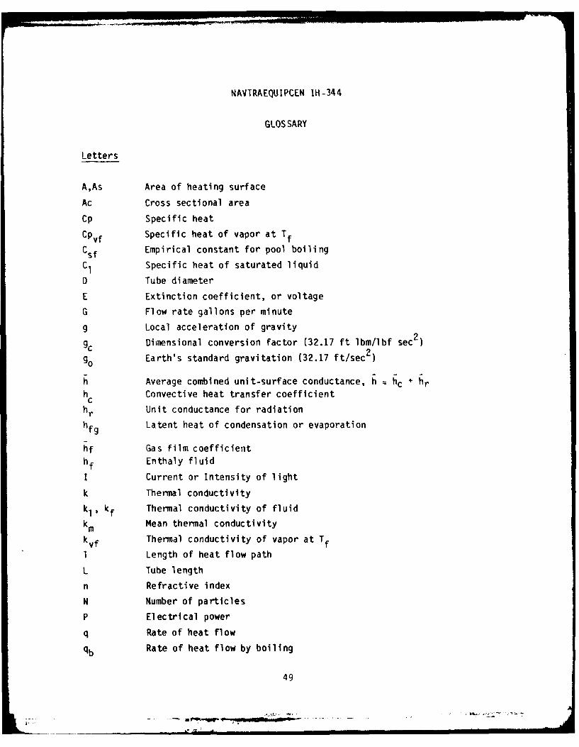
GLOSSARY
Letters
A,As Area of heating surface
Ac Cross sectional area
Cp Specific heat
CPvf Specific heat of vapor at Tf
Csf Empirical constant for pool boiling
C1 Specific heat of saturated liquid
D Tube diameter
E Extinction coefficient, or voltage
G Flow rate gallons per minute
g Local acceleration of gravity
Dimensional conversion factor (32.17 ft Ibm/lbf sec 2
90 Earth's standard gravitation (32.17 ft/sec2)
h Average combined unit-surface conductance, h hc + hrhc Convective heat transfer coefficient
hr Unit conductance for radiation
hfg Latent heat of condensation or evaporation
hf Gas film coefficient
hf Enthaly fluid
I Current or Intensity of light
k Thermal conductivity
kl, kf Thermal conductivity of fluid
k m Mean thermal conductivity
kvf Thermal conductivity of vapor at Tf
I Length of heat flow path
L Tube length
n Refractive index
N Number of particles
P Electrical power
q Rate of heat flow
qb Rate of heat flow by boiling
49
NAVTRAEQUIPCEN IH-344
qc Rate of heat flow by convection
(q/A)max Maximum or critical heat flux for boiling
(q/A)min Minimum heat flux for boiling
q Total Combined rate of heat flow
R Total electrical resistance
r Particle radius
re Unit electrical resistance
T Temperature
Tb Temperature of bulk fluid
T Mean fluid temperature
Ts Surface temperature
Tsat Saturation temperature
Tm Temperature far from heat source
AT Temperature difference
ATs =TS-Tsat' Excess temperature
ATf Temperature difference between surface and fluid
ATmin Excess temperature at point of minimum heat flux
V Average velocity
Ve, E Voltage
Greek Letters
Optical parameter
Temperature coefficient of volume expansion
A Difference between values
A, Wave length
p Absolute viscosity
m Mean viscosity
;Ab Bulk viscosity
A LI Liquid viscosity
/is Viscosity of saturated liquid
JAf Vi scosi ty of vapor at Tf
50
[ -;'- -- "a .. . . .
I I I

NAVTRAEQUIPCEN IH-344
pm Micron (10-6m)
V Kinematic viscosity, v/p
P Mass Density
P e Resistivity
P I Density of liquid
P v Density of vapor
P vf Density of vapor at Tfa Surface tension
X Quality of vapor
Dimensionless Groups
Gr Grashof number = gL 3AT/L2
GrD Diameter Grashof number = PgD3 ATI 2
Nu Nusselt number = h cL/k f
Nux Local value of Nu at point x
Nu Average value of Nu over surface = hcL/kf
NuD Diameter Nusselt number = h cD/kfPr Prandtl number c p/ /kf or v/a
Re Reynolds number = Vp L/p
ReD Diameter Reynolds number = VpD//i
51
r _awxs4-

NAVTRAEQUIPCEN IH-344
DISTRIBUTION LIST
Defense Technical Information CenterCameron StationAlexandria, VA 22314 12 copies
Technical Information CenterNAVTRAEQU IPCENOrlando, FL 32813 2 copies
NAVTRAEQU I PCENOrlando, FL 32813 25 copies
1 copy each to:
Marine Corps Liaison OfficeNAVTRAEQUIPCEN Code N-O01Orlando, FL 32813
Air Force Liaison OfficeNAVTRAEQUIPCEN Code N-002Orlando, FL 32813
PM TRADENAVTRAEQUIPCENOrlando, FL 32813
Commanding OfficerNaval Research Laboratory (Code 6180)Washington, DC 20375
Commander, Navy Safety Center(Code 20)Naval Air StationNorfolk, VA 23511
Commanding OfficerNaval Weapon Support Center(Code 5061)Crane, IN 475??
Commanding OfficerFleet Training CenterNorfolk, VA 23511
Commanding OfficerFLEMINEWARTRACEN (Code 90)Naval BaseCharleston, SC 29408
--

NAVTRAEIUIPCEN IH-344
DISTRIBUTION LISTcontinued
I copy each to:
Commanding Officer Commander, Naval Sea Systems CommandFLEBALMISUBTRACEN (Code N-960) Code 092Naval Base Washington, DC 20362Charleston, SC 29408
Chief of Naval Material Commander, Naval Sea Systems Command(NAVMAT Code 04FI) Code 55XWashington, DC 20360 Washington, DC 20362
Commanding Officer Commander, Naval Sea Systems CommandFleet Training Center Code 55X32Naval Station Washington, DC 20362San Diego, CA 92136
Chief of Naval Technical TrainingNAS Memphis (75)Millington, TN 38054
SuperintendentNational Fire AcademyU.S. Department of CommerceWashington, DC 20230
Commanding OfficerNaval Submarine SchoolBox 700Groton, CT 06340
Conmnander, Training CommandU.S. Atlantic FleetNorfolk, VA 23511
Commander, Training CommandU.S. Pacific FleetSan Diego, CA 92147
Commander, Naval Surface ForcesU.S. Pacific Fleet (Code 005/N6N)San Diego, CA 92155

DATE