hz wireless radio switches and receivers - simu...
TRANSCRIPT

Items Reference Description
2005713
2005326
2005914
20061382006139200614020061412006142
20061432006144200614520061462006147
WhiteSilverPlumGreenOrange
WhiteSilverPlumGreenOrange
1810605 White
1810606 Ivory
1810603 White
1810604 Ivory
43
Slim Single Channel Hand Held
Slim Multi Channel Hand Held
Recessed Designer Single Channel
-Indoor rated
Recessed Designer Multi Channel
-5 independent channels that can be programmedto operate one or more motors.
-Indoor rated
Single Channel Surface Wall Mount
-Available in white
-Indoor rated
Two Channel Key Chain Style Transmitter
-Available in black
-Sequence function
Four Channel Key Chain Style Transmitter
-Available in black
-Sequence function
Hz Wireless RadioSwitches and Receivers
-5 independent channels that can be programmedto operate one or more motors.
Items Reference Description
1810602
2005714
44
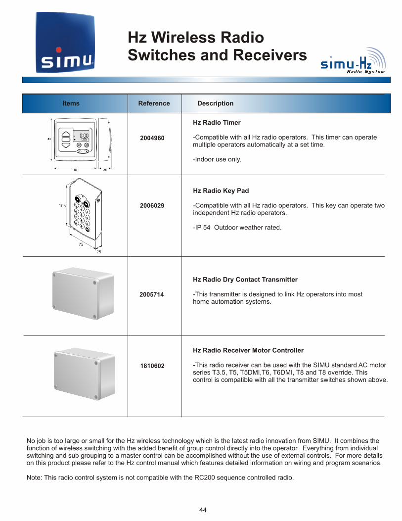
No job is too large or small for the Hz wireless technology which is the latest radio innovation from SIMU. It combines the function of wireless switching with the added benefit of group control directly into the operator. Everything from individual switching and sub grouping to a master control can be accomplished without the use of external controls. For more details on this product please refer to the Hz control manual which features detailed information on wiring and program scenarios.
Note: This radio control system is not compatible with the RC200 sequence controlled radio.
Hz Radio Receiver Motor Controller
-This radio receiver can be used with the SIMU standard AC motor series T3.5, T5, T5DMI,T6, T6DMI, T8 and T8 override. This control is compatible with all the transmitter switches shown above.
Hz Radio Dry Contact Transmitter
-This transmitter is designed to link Hz operators into most home automation systems.
Hz Wireless RadioSwitches and Receivers
2004960
2006029
Hz Radio Timer
-Compatible with all Hz radio operators. This timer can operate multiple operators automatically at a set time.
-Indoor use only.
Hz Radio Key Pad
-Compatible with all Hz radio operators. This key can operate twoindependent Hz radio operators.
-IP 54 Outdoor weather rated.
Sequence ControlledRadio
Reference Description
20056322005634
200564220056432005644
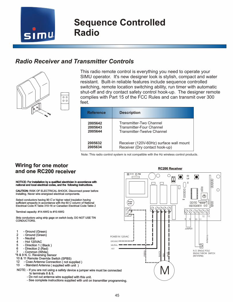
Transmitter-Two ChannelTransmitter-Four ChannelTransmitter-Twelve Channel
Receiver (120V-60Hz) surface wall mountReceiver (Dry contact hook-up)
45
RC200 Receiver RC200 Receiver
Fuse4.0A
PW
POWER IN 120VAC
HOT
NEUTRAL
GROUND
Ante
nna
JUMPER
M
N.O. SINGLE POLESINGLE THROW SWITCH(REF#SPBS)G
REEN
RED
WH
ITE
BLA
CK
LD
1122
CO
DE
MEM
ORY
8 9 10 11
12 131
22 33 44 55 66 77
Gr d Gr )1 - oun ( een 2 - Ground (Green)
t3 - Neu ral 4 - Hot 120VAC
15 - Direction ( Black ) e (6 - Dir ction 2 Red)
o t7 - C mmon (Whi e)
Gr d Gr )1 - oun ( een 2 - Ground (Green)
t3 - Neu ral 4 - Hot 120VAC
15 - Direction ( Black ) e (6 - Dir ction 2 Red)
o t7 - C mmon (Whi e) *8 & 9 N. . Re er i g e so C v s n S n r 10 & 1 em t err witch (SP S 1 R o e Ov ide S B ) 12 C x Antenn C nne t n t s plied ) - oa a o c ion ( o up 1 S and rd Ant nna ( s plied wit i 3 - t a e up h un t )
*8 & 9 N. . Re er i g e so C v s n S n r 10 & 1 em t err witch (SP S 1 R o e Ov ide S B ) 12 C x Antenn C nne t n t s plied ) - oa a o c ion ( o up 1 S and rd Ant nna ( s plied wit i 3 - t a e up h un t )
N E: - I you are ot using a afet dev ce a u p r ire mu t be connectedOT f n s y i j m e w s to er ina s 8 & . t m l 9 D not c t antenna i e sup li d ith this unit. - o u w r p e w See c mpl te instr cti ns s pplied with nit on transm tt r rog amming. - o e u o u u i e p r
N E: - I you are ot using a afet dev ce a u p r ire mu t be connectedOT f n s y i j m e w s to er ina s 8 & . t m l 9 D not c t antenna i e sup li d ith this unit. - o u w r p e w See c mpl te instr cti ns s pplied with nit on transm tt r rog amming. - o e u o u u i e p r
Radio Receiver and Transmitter Controls
W n fo ne mo oiri g r o t ra d o e R 2 0 re eiv rn n C 0 c eW n fo ne mo oiri g r o t ra d o e R 2 0 re eiv rn n C 0 c e
NOTICE: For installation by a qualified electrician in accordance with national and local electrical codes, and the following instructions.
CAUTION: RISK OF ELECTRICAL SHOCK. Disconnect power before installing. Never wire energized electrical components.
Select conductors having 90 C or higher rated insulation having sufficient ampacity in accordance with the 60 C column of National Electrical Code R Table 310-16 or Canadian Electrical Code Table 2
Terminal capacity: #14 AWG to #10 AWG
Strip conductors using strip gage on switch body. DO NOT USE TINCONDUCTORS.
NOTICE: For installation by a qualified electrician in accordance with national and local electrical codes, and the following instructions.
CAUTION:
RISK OF ELECTRICAL SHOCK. Disconnect power before installing. Never wire energized electrical components.
Select conductors having 90 C or higher rated insulation having sufficient ampacity in accordance with the 60 C column of National Electrical Code R Table 310-16 or Canadian Electrical Code Table 2
Terminal capacity: #14 AWG to #10 AWG
Strip conductors using strip gage on switch body. DO NOT USE TINCONDUCTORS.
This radio remote control is everything you need to operate your SIMU operator. It's new designer look is stylish, compact and water resistant. Built-in reliable features include sequence controlled switching, remote location switching ability, run timer with automatic shut-off and dry contact safety control hook-up. The designer remote complies with Part 15 of the FCC Rules and can transmit over 300 feet.
Note: This radio control system is not compatible with the Hz wireless control products.

Reference Unit Function
227907322791932279194
22790552279010227913922790582279054
Sun and Wind Control (white - surface mount) Sun and Wind Control (ivory - 3 gang recessed mount) Sun and Wind Control (white - 3 gang recessed mount)
Replacement / Additional Sun Sensor Replacement / Additional Rain Sensor Replacement / Additional Temperature Sensor Replacement / Additional Wind Sensor Replacement / Additional Sensor Bracket
The Halcomaster 2200USPRO allows for additional sensors to be attached. It also allows for additional switches to be remotely located.
OperatorElectronic Control Systems
46
halcomasterhalcomasterR
2200
SET
The Halcomaster 2200 is a control system for all types of window treatments. Whether you are controlling retractable awnings, rolling shutters or sun shades, the Halcomaster 2200 enables a window treatment to provide shading from the sun and protection from the wind automatically and conveniently. A digital display read out allows you to monitor the sensors sun intensity and wind speed levels. These settings can be adjusted easily from the control unit.
Automatic Environmental Controls
OPT
ION
AL
+ - R
M
een (Gr und)Gr o
Gre
en
rN t aleu0Hot (12 V-60Hz)
Whiet
Re
dBla
ck
Jumper 2200-WMWIND SENSOR
2200-LOSUN SENSOR
2200-RMRAIN SENSOR
W n o ne mo oiri g f r o t ra d o 22 0PROn ne 0W n o ne mo oiri g f r o t ra d o 22 0PROn ne 0
NOTICE: For installation by a qualified electrician in accordance with national and local electrical codes, and the following instructions.
CAUTION: RISK OF ELECTRICAL SHOCK. Disconnect power before installing. Never wire energized electrical components.
Select conductors having 90 C or higher rated insulation having sufficient ampacity in accordance with the 60 C column of National Electrical Code R Table 310-16 or Canadian Electrical Code Table 2
Terminal capacity: #14 AWG to #10 AWG
Strip conductors using strip gage on switch body. DO NOT USE TINCONDUCTORS.
NOTICE: For installation by a qualified electrician in accordance with national and local electrical codes, and the following instructions.
CAUTION:
RISK OF ELECTRICAL SHOCK. Disconnect power before installing. Never wire energized electrical components.
Select conductors having 90 C or higher rated insulation having sufficient ampacity in accordance with the 60 C column of National Electrical Code R Table 310-16 or Canadian Electrical Code Table 2
Terminal capacity: #14 AWG to #10 AWG
Strip conductors using strip gage on switch body. DO NOT USE TINCONDUCTORS.

OperatorElectronic Control Systems
47
Automatic Environmental Controls
The WINDY is designed to retract a motorized awning or sun shadeduring windy conditions, whether your home or away. The WINDY can also be used to close other window treatments such as rolling shutters during those same windy conditions. The wind sensor is adjustable and the automatic wind protection function is designed to override the manual switch during high wind gusts. Other featuresof the WINDY include the use of standard switches. Choose from designer switches, toggle switches or rocker switches.
Reference Unit Function
2005721 2009089
Wind Control for Awnings and Shades Wind Control for Rolling Shutters
120V - 60Hz120V - 60Hz
WINDY WINDY
N LN
M
Com
G nGree ( rou d)n
N utrale
H ( 2 V 6 Hzot 1 0 - 0 )
Wh
tie
Re
d
aBl
kc
WindtMe er
ind
W
Se
ep
dju
tA
ds
me
nt
Motor w tch 120V S i
Individual Switch
*
WARNINGWARNINGTHE “SWITCH COM” IS AN INTERNALLY PROVIDEDHOT (115VAC) POWER AND IS ONLY CONNECTED TO COMMON TERMINAL OF THE SWITCH. DO NOT CONNECT TO ANY EXTERNAL VOLTAGE SOURCE (LINE POWER: HOT OR NEUTRAL) AS THIS WILL CAUSE SEVERE DAMAGE TO THE CONTROL.
DO NOT
*
* NOTE: Turn the wind speed adjustment down to minimum. Spin the wind sensor and confirm t e windy h
activates in the correct direction. If the windy activates the motor in the wrong direction at a wind signal, reverse the red and black mot r leads. Remember to urno t the wind speed adju tment back s u aft r testing. p e
Turn the wind speed adjustment down to minimum. Spin the wind sensor and confirm t e windy h
activates in the correct direction. If the windy activates the motor in the wrong direction at a wind signal, reverse the red and black mot r leads. Remember to urno t the wind speed adju tment back s u aft r testing. p e
* NOTE:
W n o e mo oiri g f r on t ra i dnd one W n yW n o e mo oiri g f r on t ra i dnd one W n y
NOTICE: For installation by a qualified electrician in accordance with national and local electrical codes, and the following instructions.
CAUTION: RISK OF ELECTRICAL SHOCK. Disconnect power before installing. Never wire energized electrical components.
Select conductors having 90 C or higher rated insulation having sufficient ampacity in accordance with the 60 C column of National Electrical Code R Table 310-16 or Canadian Electrical Code Table 2
Terminal capacity: #14 AWG to #10 AWG
Strip conductors using strip gage on switch body. DO NOT USE TINCONDUCTORS.
NOTICE: For installation by a qualified electrician in accordance with national and local electrical codes, and the following instructions.
CAUTION:
RISK OF ELECTRICAL SHOCK. Disconnect power before installing. Never wire energized electrical components.
Select conductors having 90 C or higher rated insulation having sufficient ampacity in accordance with the 60 C column of National Electrical Code R Table 310-16 or Canadian Electrical Code Table 2
Terminal capacity: #14 AWG to #10 AWG
Strip conductors using strip gage on switch body. DO NOT USE TINCONDUCTORS.

OperatorElectronic Control Systems
Group Control Relays
Relay group controls can be linked together to control any amount of operators. SIMU can custom design a group control system that will give you complete control of your SIMU operators.
Reference Unit Function
2282074228207522820282282018
200571820057192005717
Two Motor Relay Group Control (master, individual) (RI.2) Three Motor Relay Group Control (master, individual) (RI.3) Two Motor Relay Group Control (master, sub group, individual) (GI.2) Two Motor Relay Group Control (24-Volt switching) (RG.2)
Two Motor Relay Group Control (master, individual) Metal Box (RI.2M) Three Motor Relay Group Control (master, individual) Metal Box (RI.3M) Two Motor Relay Group Control (24-Volt switching) Metal Box (RG.2M)
RI.2
RI.2
In
il S
wtc
div
du
ai
h In
il S
wtc
div
du
ai
h
va
lw
itc In
di
idu
Sh
va
lw
itc In
di
idu
Sh
lw
tc In
di
idu
Si
hv
al
wtc
In
di
idu
Si
hv
a
di
du
h
via
l w
itcIn
Sd
id
uh
vi
al
witc
InS
In
did
Sw
hiv
ua
litc
In
did
Sw
hiv
ua
litc
RI.3RI.3 GI.2 GI.2
S
o
ic
u
bG
ru
pS
wt
hS
o
ic
u
bG
ru
pS
wt
h
In
du
div
al S
wi
hi
tc In
du
div
al S
wi
hi
tc t Indi
dual
wch
viS
it Indi
dual
wch
viS
i
st
h M
er
Sw
ic
at
st
h M
er
Sw
ic
at
48
NOTICE: For installation by a qualified electrician in accordance with national and local electrical codes, and the following instructions.
CAUTION: RISK OF ELECTRICAL SHOCK. Disconnect power before installing. Never wire energized electrical components.
Select conductors having 90 C or higher rated insulation having sufficient ampacity in accordance with the 60 C column of National Electrical Code R Table 310-16 or Canadian Electrical Code Table 2
Terminal capacity: #14 AWG to #10 AWG
Strip conductors using strip gage on switch body. DO NOT USE TINCONDUCTORS.
NOTICE: For installation by a qualified electrician in accordance with national and local electrical codes, and the following instructions.
CAUTION:
RISK OF ELECTRICAL SHOCK. Disconnect power before installing. Never wire energized electrical components.
Select conductors having 90 C or higher rated insulation having sufficient ampacity in accordance with the 60 C column of National Electrical Code R Table 310-16 or Canadian Electrical Code Table 2
Terminal capacity: #14 AWG to #10 AWG
Strip conductors using strip gage on switch body. DO NOT USE TINCONDUCTORS.
M
P
Ground (Green)
Hot Power L1 (Black)
Common N (White)
Motor
Power to Ind. Switch
Motor Direction (Red/Black)
Note: Connections are only at terminals

OperatorElectronic Control Systems
Wiring Relays
RI2
P P
M M
NN
CENTRALCENTRAL
NNNN L L
POWER IN 115VACPOWER IN 115VAC GROUNDGROUND
5AMP MAX5AMP MAX
INDIVIDUAL SWITCH
INDIVIDUAL SWITCH
RI3
NN
CENTRALCENTRAL
NNNN L L
POWER IN 115VACPOWER IN 115VAC GROUNDGROUND
5AMP MAX5AMP MAX
N
P
M
INDIVIDUAL SWITCH
P
M
INDIVIDUAL SWITCH
P
M
INDIVIDUAL SWITCH* Three Motors
* One Momentary Master Switch* Three Momentary Individual Control Switches
* Three Motors * One Momentary Master Switch* Three Momentary Individual Control Switches
o M* Tw otors O n a M h* ne Mome t ry aster SwitcT n a v o i* wo Mome t ry Indi idual Contr l Sw tches
o M* Tw otors O n a M h* ne Mome t ry aster SwitcT n a v o i* wo Mome t ry Indi idual Contr l Sw tches
1 Hz5V - 6011 Hz5V - 601 RI.3 RI.3
Ma
se
r w
ct
Sit
h M
as
er
wc
tS
ith
n
vS
cI
di
idu
al
wit
h n
vS
cI
di
idu
al
wit
h
n
dv
Sc
Ii
idu
al
wit
h n
dv
Sc
Ii
idu
al
wit
h
n
div
idu
a S
wtc
hI
li
n
div
idu
a S
wtc
hI
li
611 - Hz5V 0611 - Hz5V 0 RI.2
RI.2
ast
Sw
h M
er
itca
stS
wh
Me
r itc
Id
ivu
Sw
cn
ida
l it
h I
div
uS
wc
nid
al
ith
Id
ivu
aS
wc
nid
l it
h I
div
ua
Sw
cn
idl
ith
49

M
M
GR -2
L L
MASTER SWITCH BUS LINE (CENTRAL)
1
2
MOTOR 1 SWITCH
MOTOR 2 SWITCH
24VDC 0.1AMPS PER RG2 IN GROUP
FUSE 5AT
120VAC POWER
MOTOR1 MOTOR2
P P
HOT
NEUTRAL
GROUND
NN NNN
Master Control(AV or switch)
Individual switches can be linked to form a subgroup
Individual switches can be linked to form a subgroup
Mp
pM
1 51 v
P12 V0
Mp P P
GI2
M M
OperatorElectronic Control Systems
Wiring Relays
o M* Tw otors O n a M h* ne Mome t ry aster SwitcOn r i* e Momentary Sub G oup Sw tch
l o * Two Momentary Individua C ntrol Switches
o M* Tw otors O n a M h* ne Mome t ry aster SwitcOn r i* e Momentary Sub G oup Sw tch
l o * Two Momentary Individua C ntrol Switches
1 Hz5V - 6011 Hz5V - 601 RG.2 RG.2
Ma
se
r w
ct
Sit
h M
as
er
wc
tS
ith
n
vS
cI
di
idu
al
wit
h n
vS
cI
di
idu
al
wit
h
n
dv
Sc
Ii
idu
al
wit
h n
dv
Sc
Ii
idu
al
wit
h
611 - Hz5V 0611 - Hz5V 0 GI.2 GI.2
ast
Sw
h M
er
itca
stS
wh
Me
r itc
Id
ivu
Sw
cn
ida
l it
h I
div
uS
wc
nid
al
ith
Id
ivu
aS
wc
nid
l it
h I
div
ua
Sw
cn
idl
ith
* Tw Motors o* Low-Voltage Momentary M ster Swi cha t* Two Lo -V ltage Momentary Individual Control Switchesw o
* Tw Motors o* Low-Voltage Momentary M ster Swi cha t* Two Lo -V ltage Momentary Individual Control Switchesw o
50

OperatorElectronic Control SystemsLow Voltage
Never be without POWER!
Reference Description
2005716
2005586
2005715 Battery back up system with warning lights (white)
Battery back up system with warning lights (ivory)
Battery Replacement 12v 1.2 amp hour
STOP
Power On Line
PowerOff Line
LowBattery
51
TECHNICAL DATA:Input Voltage 120 VAC 50/60HzInput Current 50 mAMotor Output Voltage 12 Volts NominalMotor Output Current 5 Amps Max. PolyfusedBattery Output Voltage/Current Regulated Charging for 12 Volt 1.2 Ah Sealed Lead Acid Battery,Standby Battery Current 6.5 mAShut Down Battery Current .9mASize 3.5“ X 2.5” (Fits in deep 2 gang plastic box supplied)External Switching N.O., Momentary Dry Contacts Rated for 12 VoltsBus Line 12 Volts DC
MOTOR
NL
G
+ _
UD
SG
BU
SU
DS
+12
SWITC
H
JP1
+
-
BATTERY12VOLT 1.2 AhREF#2005586
BROWN
BLUE
MASTER/LOCALSWITCH JUMPER
EXTERNAL SWITCH U UP D DOWN S STOP+12 COMMON
BUS LINECONNECT TO ALLBBU’S IN A GROUP
LINE POWER 120VAC(G) GROUND(L) LINE(N) NEUTRAL
REF# BBU
RED BLACK
JP1
Jumpers offexternal switchescontrol only this BBU
LOCAL
JP1
Jumpers onexternal switches controlall BBUs connected bybus line
MASTEREXTERNAL SWITCH MASTER/LOCAL
Motor Wire 16 gage min.20 foot max length
W n o e Diri g f r on C motora S ind one BB Un tW n o e Diri g f r on C motora S ind one BB Un t
NOTICE: For installation by a qualified electrician in accordance with national and local electrical codes, and the following instructions.
CAUTION: RISK OF ELECTRICAL SHOCK. Disconnect power before installing. Never wire energized electrical components.
Select conductors having 90 C or higher rated insulation having sufficient ampacity in accordance with the 60 C column of National Electrical Code R Table 310-16 or Canadian Electrical Code Table 2
Terminal capacity: #14 AWG to #10 AWG
Strip conductors using strip gage on switch body. DO NOT USE TINCONDUCTORS.
NOTICE: For installation by a qualified electrician in accordance with national and local electrical codes, and the following instructions.
CAUTION:
RISK OF ELECTRICAL SHOCK. Disconnect power before installing. Never wire energized electrical components.
Select conductors having 90 C or higher rated insulation having sufficient ampacity in accordance with the 60 C column of National Electrical Code R Table 310-16 or Canadian Electrical Code Table 2
Terminal capacity: #14 AWG to #10 AWG
Strip conductors using strip gage on switch body. DO NOT USE TINCONDUCTORS.
The BBU is designed to provide you with constant power to any SIMU DC operator. The BBU operates from a battery that is charging while standard AC current is available. Three LED lights on the front of the unit keep you informed on your current power conditions. The unit also has additional dry contact connections for external switching devices such as home automation systems.
Battery Back-up System

OperatorElectronic ControlsSecurity Key Switches
52
Items Reference Description
2001547
2001549
2001548
2001550
2001551
2001552
2005616
2005614
2005752
2005613
Single Pole, Double Throw, Maintained Contact
-Surface mount
-Recessed mount
Single Pole, Double Throw, Momentary Contact
-Surface mount
-Recessed mount
Commercial Grade Single Pole, Double Throw, Momentary Contact
-Surface mount
Commercial GradeSingle Pole, Double Throw, Momentary Contact
-Recessed mount
Single Pole, Single Throw, Momentary Contact
-Surface mount
-Recessed mount
Standard Key Switch Extra Keys
Commercial Grade Extra Keys
* 3 keys included.
* 3 keys included.
* 3 keys included.
* 3 keys included.
* 3 keys included.

OperatorElectronic ControlsSecurity Key Switches
53
Wi ng for ne mo ori o t rand o e ke w tch s itchn y s i wWi ng for ne mo ori o t rand o e ke w tch s itchn y s i w
NOTICE: For installation by a qualified electrician in accordance with national and local electrical codes, and the following instructions.
CAUTION: RISK OF ELECTRICAL SHOCK. Disconnect power before installing. Never wire energized electrical components.
Select conductors having 90 C or higher rated insulation having sufficient ampacity in accordance with the 60 C column of National Electrical Code R Table 310-16 or Canadian Electrical Code Table 2
Terminal capacity: #14 AWG to #10 AWG
Strip conductors using strip gage on switch body. DO NOT USE TINCONDUCTORS.
NOTICE: For installation by a qualified electrician in accordance with national and local electrical codes, and the following instructions.
CAUTION:
RISK OF ELECTRICAL SHOCK. Disconnect power before installing. Never wire energized electrical components.
Select conductors having 90 C or higher rated insulation having sufficient ampacity in accordance with the 60 C column of National Electrical Code R Table 310-16 or Canadian Electrical Code Table 2
Terminal capacity: #14 AWG to #10 AWG
Strip conductors using strip gage on switch body. DO NOT USE TINCONDUCTORS.
* One M to o r* One Key Switc h* One M to o r* One Key Switc h
Key SwitchKey Switch
bReference Num ers16 M y s20056 omentar key witch, surface mount
a es2005614 Moment ry key switch, rec sed mount
Green (Ground)
White (Neutra )l
Hot (120V-60Hz)
Motor RedMoto B ackr l
Motor Black
(Key Switch)
YellowBlue
Ora
ng
e
Ora
ng
e
* One Motor * One Key Switch
* One Motor * One Key Switch
Key SwitchKey Switch
bReference Num ers2001548 - Momentary key switch, surface mount2001550 - Momentary key switch, recessed mount
G ee (Gro ndr n u )White (Neutral)
Hot (120V-60Hz)
Motor Red
p wiJum er re
Motor Black
or l ckMot B a
wi h)(Key S tcGreen (Ground)t N rWhi e ( eut al)
B ack ( Hot 20V-6 Hz)l 1 0
M tor Redo
Motor Black
r lMoto B ack
c(Key Swit h)
G een (G ou d)r r n
Green (Ground)
k ( Blac Hot 120V-60Hz)
* One M to o r* One Key Switc h* One M to o r* One Key Switc h
Key SwitchKey Switch
Ref ence Number ers2001547 - aint n key s ch, s face mountM ai ed wit ur
- M ntai ed k witc eces ed mount2001549 ai n ey s h, r s
n n War i g N i e e h t DO OT wr mor t an one operator o si swt oper or a ngle pole i ch. A second at b e pol o a can e wir d to the second e f pol sw double e itch.
c swt ODO N T onnect two i ches to an per e o ator without a r lay.
n n War i g N i e e h tDO OT wr mor t an one operator o si swt oper or a ngle pole i ch. A second at b e pol o a can e wir d to the second e f pol sw double e itch.
c swt ODO N T onnect two i ches to an per e o ator without a r lay.

OperatorElectronic ControlsDesigner Switches
200555320055582005526
200555420055592005527
200554920055552005525
20055502005556
Designer Switch - Single Pole, Double Throw (Maintained - Ivory)Designer Switch - Single Pole, Double Throw (Momentary - Ivory)Designer Switch - Double Pole, Double Throw (Maintained - Ivory)
Designer Switch - Single Pole, Double Throw (Maintained - White)Designer Switch - Single Pole, Double Throw (Momentary - White)Designer Switch - Double Pole, Double Throw (Maintained - White)
Designer Switch - Single Pole, Double Throw (Maintained - Almond)Designer Switch - Single Pole, Double Throw (Momentary - Almond)Designer Switch - Double Pole, Double Throw (Maintained - Almond)
Designer Switch - Single Pole, Double Throw (Maintained - Black)Designer Switch - Single Pole, Double Throw (Momentary - Black)
54
Items Reference Description
E d re t oi c i n 1R D E d re t oi c i n 1R D
C d r tLAK e o 2B i c i nC d r tLAK e o 2B i c i n
B C 1 v 0LA ( 0 - 6h z )K 2B C 1 v 0LA ( 0 - 6h z )K 2P we om wa lo r fr lP we om wa lo r fr l
H rTE ( n t a W I eu l )H rTE ( n t a W I eu l )
TE ( n t WHI eu r la )TE ( n t WHI eu r la )
N gron du )GREE ( N gron du )GREE (
EE ( g unro d )GR NEE ( g unro d )GR N
A1
A1
B1
B1
L1L1
Power inHot BlackNeutral WhiteGround Green
Motor LeadsDirection 1 RedDirection 2 BlackNeutral WhiteGround Green
Wi n fo ne mo ori g r o t rand o e de i ne wit hn s g r s cWi n fo ne mo ori g r o t rand o e de i ne wit hn s g r s cNOTICE: For installation by a qualified electrician in accordance with national and local electrical codes, and the following instructions.
CAUTION: RISK OF ELECTRICAL SHOCK. Disconnect power before installing. Never wire energized electrical components.
Select conductors having 90 C or higher rated insulation having sufficient ampacity in accordance with the 60 C column of National Electrical Code R Table 310-16 or Canadian Electrical Code Table 2
Terminal capacity: #14 AWG to #10 AWG
Strip conductors using strip gage on switch body. DO NOT USE TINCONDUCTORS.
NOTICE: For installation by a qualified electrician in accordance with national and local electrical codes, and the following instructions.
CAUTION:
RISK OF ELECTRICAL SHOCK. Disconnect power before installing. Never wire energized electrical components.
Select conductors having 90 C or higher rated insulation having sufficient ampacity in accordance with the 60 C column of National Electrical Code R Table 310-16 or Canadian Electrical Code Table 2
Terminal capacity: #14 AWG to #10 AWG
Strip conductors using strip gage on switch body. DO NOT USE TINCONDUCTORS.
Designer Cover Plates200553220055362005539
200553320055372005540
200552820055342005538
20055292005535
Designer Cover Plate 1 Gang, IvoryDesigner Cover Plate 2 Gang, IvoryDesigner Cover Plate 3 Gang, Ivory
Designer Cover Plate 1 Gang, WhiteDesigner Cover Plate 2 Gang, WhiteDesigner Cover Plate 3 Gang, White
Designer Cover Plate 1 Gang, AlmondDesigner Cover Plate 2 Gang, AlmondDesigner Cover Plate 3 Gang, Almond
Designer Cover Plate 1 Gang, BlackDesigner Cover Plate 2 Gang, Black
W n n ar i g O N T i e e han t D O wr mor t one operator o si e swt se oper or a ngl pole i ch. A cond at be ed o t se pol of a can wir t he cond e pol swt double e i ch.
con swt t a ODO N T nect two i ches o n pera i ho el . o tor wt ut a r ay
W n n ar i g O N T i e e han tD O wr mor t one operator o si e swt se oper or a ngl pole i ch. A cond at be ed o t se pol of a can wir t he cond e pol swt double e i ch.
con swt t a ODO N T nect two i ches o n pera i ho el . o tor wt ut a r ay
OperatorElectronic ControlsToggle Switches
55
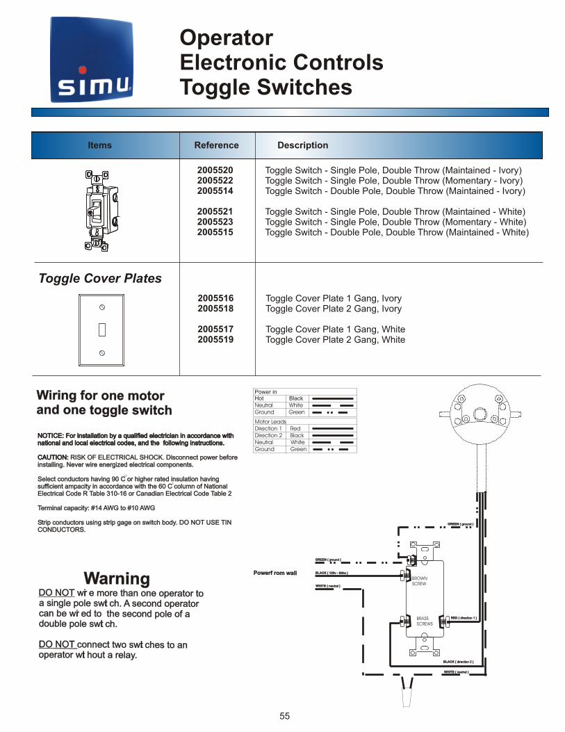
200552020055222005514
200552120055232005515
20055162005518
20055172005519
Toggle Switch - Single Pole, Double Throw (Maintained - Ivory)Toggle Switch - Single Pole, Double Throw (Momentary - Ivory)Toggle Switch - Double Pole, Double Throw (Maintained - Ivory)
Toggle Switch - Single Pole, Double Throw (Maintained - White)Toggle Switch - Single Pole, Double Throw (Momentary - White)Toggle Switch - Double Pole, Double Throw (Maintained - White)
Toggle Cover Plate 1 Gang, IvoryToggle Cover Plate 2 Gang, Ivory
Toggle Cover Plate 1 Gang, WhiteToggle Cover Plate 2 Gang, White
Items Reference Description
D ( direc ion 1t RE )D ( direc ion 1t RE )
B A d r t 2i ec ion )L CK ( B A d r t 2i ec ion )L CK (
B A 6L CK ( 120v - 0hz ) B A 6L CK ( 120v - 0hz ) werf r m w lPo o a lwerf r m w lPo o a l
WH T ( eut al I E n r )WH T ( eut al I E n r )
TE ( eu a WHI t ln r )TE ( eu a WHI t ln r )
GR E gr ndou E N ( )GR E gr ndou E N ( )
GR E gr doun E N ( )GR E gr doun E N ( )
BROWN SCREW
BRASSSCREWS
Power inHot BlackNeutral WhiteGround Green
Motor LeadsDirection 1 RedDirection 2 BlackNeutral WhiteGround Green
W n o ne mo oiri g f r o t ra d o t g e s itcn ne og l w hW n o ne mo oiri g f r o t ra d o t g e s itcn ne og l w h
NOTICE: For installation by a qualified electrician in accordance with national and local electrical codes, and the following instructions.
CAUTION: RISK OF ELECTRICAL SHOCK. Disconnect power before installing. Never wire energized electrical components.
Select conductors having 90 C or higher rated insulation having sufficient ampacity in accordance with the 60 C column of National Electrical Code R Table 310-16 or Canadian Electrical Code Table 2
Terminal capacity: #14 AWG to #10 AWG
Strip conductors using strip gage on switch body. DO NOT USE TINCONDUCTORS.
NOTICE: For installation by a qualified electrician in accordance with national and local electrical codes, and the following instructions.
CAUTION:
RISK OF ELECTRICAL SHOCK. Disconnect power before installing. Never wire energized electrical components.
Select conductors having 90 C or higher rated insulation having sufficient ampacity in accordance with the 60 C column of National Electrical Code R Table 310-16 or Canadian Electrical Code Table 2
Terminal capacity: #14 AWG to #10 AWG
Strip conductors using strip gage on switch body. DO NOT USE TINCONDUCTORS.
Toggle Cover Plates
W n n ar i g O N T i e e han t D O wr mor t one operator o si e swt se oper or a ngl pole i ch. A cond at be i ed o t se pol of a can wr t he cond e pol swt double e i ch.
conn swt t an ODO N T ect two i ches o pera i ho el . o tor wt ut a r ay
W n n ar i g O N T i e e han tD O wr mor t one operator o si e swt se oper or a ngl pole i ch. A cond at be i ed o t se pol of a can wr t he cond e pol swt double e i ch.
conn swt t an ODO N T ect two i ches o pera i ho el . o tor wt ut a r ay
OperatorElectronic ControlsRocker Switches
56
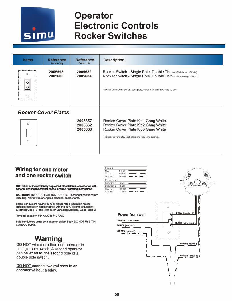
20055982005600
20056822005684
200565720056622005668
Items Reference Reference Description Switch Only Switch Kit
W n o ne mo oiri g f r o t ra d o roc er s itn ne k w chW n o ne mo oiri g f r o t ra d o roc er s itn ne k w ch
W n n ar i g O N T i e e han t D O wr mor t one operator o si e swt se oper or a ngl pole i ch. A cond at be i ed o t se pol of a can wr t he cond e pol swt double e i ch.
conn swt t an ODO N T ect two i ches o pera i ho el . o tor wt ut a r ay
W n n ar i g O N T i e e han tD O wr mor t one operator o si e swt se oper or a ngl pole i ch. A cond at be i ed o t se pol of a can wr t he cond e pol swt double e i ch.
conn swt t an ODO N T ect two i ches o pera i ho el . o tor wt ut a r ay
NOTICE: For installation by a qualified electrician in accordance with national and local electrical codes, and the following instructions.
CAUTION: RISK OF ELECTRICAL SHOCK. Disconnect power before installing. Never wire energized electrical components.
Select conductors having 90 C or higher rated insulation having sufficient ampacity in accordance with the 60 C column of National Electrical Code R Table 310-16 or Canadian Electrical Code Table 2
Terminal capacity: #14 AWG to #10 AWG
Strip conductors using strip gage on switch body. DO NOT USE TINCONDUCTORS.
NOTICE: For installation by a qualified electrician in accordance with national and local electrical codes, and the following instructions.
CAUTION:
RISK OF ELECTRICAL SHOCK. Disconnect power before installing. Never wire energized electrical components.
Select conductors having 90 C or higher rated insulation having sufficient ampacity in accordance with the 60 C column of National Electrical Code R Table 310-16 or Canadian Electrical Code Table 2
Terminal capacity: #14 AWG to #10 AWG
Strip conductors using strip gage on switch body. DO NOT USE TINCONDUCTORS.
Power inHot BlackNeutral WhiteGround Green
Motor LeadsDirection 1 RedDirection 2 BlackNeutral WhiteGround Green
aPower from w llaPower from w ll d c 1RED ( ire tion ) d c 1RED ( ire tion )
BLACK ( direction 2 )BLACK ( direction 2 )
K 2 0 z )BLAC ( 1 0v - 6 hK 2 0 z )BLAC ( 1 0v - 6 h
W TE ( eutraHI n l )W TE ( eutraHI n l )
( e aWHITE n utr l ) ( e aWHITE n utr l )
GREEN ( ground )GREEN ( ground )
G EN ( ro ndg u )RE G EN ( ro ndg u )RE
Rocker Switch - Single Pole, Double Throw (Maintained - White)
Rocker Switch - Single Pole, Double Throw (Momentary - White)
- Switch kit includes: switch, back plate, cover plate and mounting screws
Rocker Cover Plate Kit 1 Gang WhiteRocker Cover Plate Kit 2 Gang WhiteRocker Cover Plate Kit 3 Gang White
-Includes cover plate, back plate and mounting screws.
Rocker Cover Plates

OperatorElectronic ControlsTransformers and Motor Cable
200596820056472005637
HARDWIRE - 6 AMP - 12 VOLTSHARDWIRE - 8 AMP - 12 VOLTSHARDWIRE - 10 AMP - 12 VOLTS
HARDWIRE - 6 AMP - 24 VOLTSHARDWIRE - 8 AMP - 24 VOLTSHARDWIRE - 10 AMP - 24 VOLTSHARDWIRE - 12 AMP - 24 VOLTS
2005604200560520056392005641
91280972005749
3 CONDUCTORS PLUS GROUND (white)3 CONDUCTORS PLUS GROUND (gray)
Transformers
Motor Cable
57
Items Reference Description