hyundai inverter - equattro sas | marchi materiale … · superb speed control performance by...
TRANSCRIPT

HYUNDAIINVERTER
| The Controlling Solution of Powerful Inverter Brand |

Hyundai’s Technology for the BestHigh performance inverter for efficient business design
the best future with series

Series with Powerful Control Solution
l Excellent Applicability to Various Loads l
l Easy Maintenance & Simple Repair l
l High Reliability & Durability l
l Compliance with RoHS l
l Lower Audible Noise l

For the highest quality,for the highest customer satisfaction
HYUNDAI N700E series inverter with high durability, elaborate speed controllability and excellent torque responsibility provides superb operability.
The N700E’s compact size and sensorless vector control technology provide perfectly optimized performance for industrial equipment.
Certificates of international standards (CE, UL/cUL) of N700E series make its applications ready for global business.
Model Name IndicationModel Name Indication
Series name
Power sourceSF: 1-Phase, 220VLF: 3-Phase, 220VHF: 3-Phase, 440V
N700E-004SFN700E-007SFN700E-015SFN700E-022SF
1-Phase, 220V 3-Phase, 220VN700E-004LFN700E-007LFN700E-015LFN700E-022LFN700E-037LFN700E-055LFN700E-075LFN700E-110LFN700E-150LFN700E-185LFN700E-220LF
N700E-004HFN700E-007HFN700E-015HFN700E-022HFN700E-037HFN700E-055HFN700E-075HFN700E-110HFN700E-150HFN700E-185HFN700E-220HFN700E-300HFN700E-370HFN700E-450HFN700E-550HFN700E-750HFN700E-900HFN700E-1100HFN700E-1320HFN700E-1600HFN700E-2200HFN700E-2800HFN700E-3500HF
3-Phase, 440V
N700E
004 : 0.4kW
055 : 5.5kW
3500 : 350kW
Add OptionR: DC Reactor
055 LF R
Model Configuration
Clean PowerHyundai Inverter
400V 22kW
Applicable motor capacity
0.40.71.52.23.75.57.51115
18.522303745557590
110132160220280350
Applicable motor capacity(kW)
>
~~
~~

C o n t e n t s
06 Features / 08 Specifications / 10 Dimensions / 13 Operations /14 Function Lists
20 Terminal Functions / 22 Connecting Diagram /23 Connection to PLC
24 Protective Functions / 25 Wiring and Options /34 For Correct Operation
Easy Operation
Multi-Function
Simple Design
High Performance
Economical Efficiency

ㅣFeaturesㅣ
∷ Improved Control Performance
High Torque Performance in Ultra Low Speed Zone by Using Sensorless Vector Control
Hyundai’s advanced sensorless vector control technology provides a motor with high torque performance in ultra low speed zone (Sensorless vector control: above 150% at 1Hz).
In case of fast acceleration/deceleration of motor, N700E series provides powerful torque controllability without trip.
Sensorless vector control technology expands the range of controlling speed.
Superb Speed Control Performance by Improved Tuning Technology for Motors
Through technology of compensating the motor time constant while motor tuning minimizes the speed change, stable motor opeation can be achieved.
Intensified Protective Functions for Safety while Running
Ground fault protection can prevent accidents.
Countermeasure for output's phase loss protects motor while running.
Built-in Regenerative Braking System
BRD is basically equipped with the inverter so that the easy operation for acceleration/deceleration time is achieved without additional options.
Driving performance of acceleration and deceleration maximizes efficiency.
Enhanced Flexibility for Various Loads
Built in PID function uniformly controls oil pressure and flow quantity without additional options.
Improved torque characteristic, which is reduced to the 1.7th power, perfectly fits with loads for fans and pumps.
Optimized energy saving according to the characteristics of loads is achieved.
Various Inverter Display Functions
The operational status of the inverter are displayed on the monitor so that an user can understand the condition of the inverter.
Cumulative hours of driving time and the actual running time are displayed for easy maintenance.
Convenient Maintenance and Repair
N700E is available to replace the fan without separation.
Fan on/off function increases fan's durability and minimizes fan's noise.

∷ Various Load Compatibility
Fan & Pump
Water supply pump
Cooling water circulation pump
Boiler water supply pump
Air Conditioning & Dust Collecting Fan
Energy saving by selecting torque characteristic of a load Restart function in case of momentary power interruption Factory automation by PLC Machine protection by soft start/stop Auto operation by precise PID control function Low noise operation Quick responsiveness to load change by frequency jump and
multi speed operation
Cooling Tower
Stable operation by supplying high qualified energy Energy saving by speed and torque control
Conveyor & Transport Machine
Conveyor
Multi relay output terminal Accurate acceleration & deceleration Overweight prevention by using over-torque signal Prevention of load slippage by curve acceleration and
deceleration
Factory Automation
Factory automation with PLC High speed torque response to prevent slip down Soft start and stop
Textile Machine
Spinning Machine
Soft start/stop for prevention of snap and cut off Unit design for tough circumstances (dust, cotton) Improvement of product quality by stable operating speed
Washing Machine
Washing Machine
Powerful torque boost function Over torque limit function Separate setting of acceleration and deceleration time Built-in regenerative braking unit (below 22kW) Soft start/stop
HYUNDAI INVERTER 06 07

ㅣSpecificationsㅣ
440V 3-Phase
Inverter model (N700E- )
Max. Available motor(4P, kW)
Rated Capacity(kVA)
Weight(kg)
Rated Output Current(A)
Brake
Rated Input AC Voltage
Rated Output Voltage
Heavy Duty
Normal Duty
Heavy Duty
Normal Duty
Heavy Duty
Normal Duty
Recover Brake
Resistance(Ω)
007HF
0.75
-
2.8
-
3.4
-
180
1.5
015HF
1.5
-
4
-
4.8
-
180
1.5
022HF
2.2
-
6
-
7.2
-
100
1.5
037HF
3.7
-
7.6
-
9.2
-
100
2.0
055HF
5.5
7.5
10.0
12.5
12
15
70
4.2
075HF
7.5
11.0
13.3
18.2
16
22
50
4.5
110HF
11.0
15.0
19.1
24.1
23
29
50
4.5
150HF
15.0
18.5
26.6
30.7
32
37
30
7.0
185HF
18.5
22.0
31.6
35.7
38
43
20
7.0
220HF
22.0
30.0
37.4
47.3
45
57
20
7.5
004HF
0.4
-
1.5
-
1.8
-
180
1.5
220V 1-Phase/3-Phase
Inverter Model (N700E- )
Max. Available motor(4P, kW)
Rated Capacity(kVA)
Weight(kg)
Rated Output Current(A)
Brake
Rated Input AC VoltageRated Output Voltage
Heavy Duty
Normal Duty
Heavy Duty
Normal Duty
Heavy Duty
Normal Duty
Recover Brake
Resistance(Ω)
004SF
0.4
-
1.2
-
3
-
50
1.2
007SF
0.75
-
2.1
-
5
-
50
1.2
015SF
1.5
-
2.9
-
7
-
50
1.5
022SF
2.2
-
4.6
-
11
-
50
1.5
004LF
0.4
-
1.2
-
3
-
50
1.2
007LF
0.75
-
2.1
-
5
-
50
1.2
015LF
1.5
-
2.9
-
7
-
50
1.2
022LF
2.2
-
4.6
-
11
-
50
1.5
037LF
3.7
-
7.1
-
17
-
35
2.0
055LF
5.5
7.5
10.0
12.5
24
30
17
4.2
075LF
7.5
11.0
13.3
18.2
32
44
17
4.5
110LF
11.0
15.0
18.7
24.1
45
50
17
4.5
150LF
15.0
18.5
26.6
30.3
64
73
8.7
6.5
185LF
18.5
22.0
31.6
35.3
76
85
6
7.5
220LF
22.0
-
37.4
-
90
-
6
8.0
440V 3-Phase
Inverter model (N700E- )
Max. Available motor(4P, kW)
Rated Capacity(kVA)
Weight(kg)
Rated Output Current(A)
Brake
Rated Input AC VoltageRated Output Voltage
Heavy Duty
Normal Duty
Heavy Duty
Normal Duty
Heavy Duty
Normal Duty
Recover Brake
Resistance(Ω)
300HF
30
37
48.2
58.1
58
70
22
370HF
37
45
62.4
70.1
75
85
22
450HF
45
55
74.8
87.2
90
105
27
550HF
55
75
91.5
112
110
135
30
750HF
75
90
123.9
133
149
160
50
900HF
90
110
146.3
162
176
195
50
1100HF
110
132
180.4
191
217
230
60
1320HF
132
160
216.2
245
260
285
60
1600HF
160
200
230
285
300
370
110
2200HF
220
250
315
360
415
450
110
2800HF
280
320
400
470
525
600
170
3500HF
350
375
500
550
656
680
170
1-Phase 200~240V±10%, 50/60Hz±5%,
3-Phase 200~240V(Defend on receiving voltage)
Built in Brake Circuit(Need to Additional Brake Resistor)
3-Phase 200~240V±10%, 50/60Hz±5%,
3-Phase 200~240V(Defend on receiving voltage)
Built in Brake Circuit(Need to additional brake resistor)
3-Phase 380~480V±10%, 50/60Hz±5%,
3-Phase 380~480V(Defend on receiving voltage)
Built in Brake Circuit(Need to additional brake resistor)
3-Phase 380~480V±10%, 50/60Hz±5%,
3 Phase 380~480V(Defend on receiving voltage)
Need to Setup Recover Brake Unit
Refer to Option Table (Page 32)
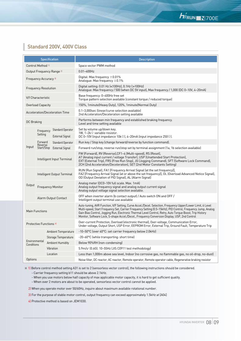
Standard 200V, 400V Class
Specification
Control Method 1)
Output Frequency Range 2)
Frequency Accuracy 3)
Frequency Resolution
V/f Characteristic
Overload Capacity
Acceleration/Deceleration Time
DC Braking
Input
Frequency Setting
Standard Operator
External Signal
Standard Operator
External Signal
Forward Reverse Start/Stop
Intelligent Input Terminal
Intelligent Output Terminal
Frequency Monitor
Alarm Output Contact
Output
Environmental Conditions
Main Functions
Protective Functions 4)
Options
Ambient Temperature
Storage Temperature
Ambient Humidity
Vibration
Location
Description
Space vector PWM method
0.01~400Hz
Digital: Max frequency ±0.01%Analogue: Max frequency ±0.1%
Digital setting: 0.01 Hz (<100Hz), 0.1Hz (>100Hz) Analogue: Max frequency / 500 (when DC 5V input), Max frequency / 1,000 (DC 0~10V, 4~20mA)
Base frequency: 0~400Hz free set Torque pattern selection available (constant torque / reduced torque)
150%, 1minute(Heavy Duty), 120%, 1minute(Normal Duty)
0.1~3,000sec (linear/curve selection available) 2nd Acceleration/Deceleration setting available
Performs between min frequency and established braking frequency. Level and time setting available
Set by volume up/down key. 1W, 1~2kΩ variable resistor. DC 0~10V (input impedance 10kΩ), 4~20mA (input impedance 250Ω).
Run key / Stop key (change forward/reverse by function command).
Forward run/stop, reverse run/stop set by terminal assignment (1a, 1b selection available)
FW (Forward), RV (Reverse),CF1~4 (Multi-speed), RS (Reset), AT (Analog input current / voltage Transfer), USP (Unattended Start Protection), EXT (External Trip), FRS (Free Run Stop), JG (Jogging Command), SFT (Software Lock Command), 2CH (2nd Acceleration/Deceleration), SET (2nd Motor Constants Setting)
RUN (Run Signal), FA1 [Frequency Arrival Signal (at the set frequency)],FA2 [Frequency Arrival Signal (at or above the set frequency)], OL (Overload Advanced Notice Signal), OD (Output Deviation of PID Signal), AL (Alarm Signal)
Analog meter (DC0~10V full scale. Max. 1mA)Analog output frequency signal and analog output current signal Analog output voltage signal selection available.
OFF when inverter alarm (b contact output) / Auto switch ON and OFF / Intelligent output terminal use available
Auto-tuning, AVR Function, V/F Setting, Curve Accel./Decel. Selection, Frequency Upper/Lower Limit, 6 Level Multi-speed, Start Frequency Set, Carrier Frequency Setting (0.5~15kHz), PID Control, Frequency Jump, Analog Gain Bias Control, Jogging Run, Electronic Thermal Level Control, Retry, Auto Torque Boost, Trip History Monitor, Software Lock, S-shape Accel./Decel., Frequency Conversion Display, USP, 2nd Control
Over-current Protection, Overload (electronic thermal), Over-voltage, Communication Error, Under-voltage, Output Short, USP Error, EEPROM Error, External Trip, Ground Fault, Temperature Trip
-10~50°C (over 40°C: set carrier frequency below 2.0kHz)
-20~60°C (while transporting: short time)
Below 90%RH (non-condensing)
5.9m/s2 (0.6G). 10~55Hz (JIS C0911 test methodology)
Less than 1,000m above sea level, Indoor (no corrosive gas, no flammable gas, no oil-drop, no-dust)
Noise filter, DC reactor, AC reactor, Remote operator, Remote operator cable, Regenerative braking resistor
※ 1) Before control method setting A31 is set to 2 (sensorless vector control), the following instructions should be considered. - Carrier frequency setting b11 should be above 2.1kHz. - When you use motors below half capacity of max applicable motor capacity, it is hard to get sufficient quality. - When over 2 motors are about to be operated, sensorless vector control cannot be applied.
2) When you operate motor over 50/60Hz, inquire about maximum available rotational number.
3) For the purpose of stable motor control, output frequency can exceed approximately 1.5kHz at [A04]
4) Protective method is based on JEM1030.
HYUNDAI INVERTER 08 09

ㅣDimensionsㅣ
61286
1282-4.2
66
412
04
128
140
6147
24
(5.4)14068
9038
128
2-Ø4.2 관통
246
275
189210
2-Ø7
7
168
[Unit:mm]
N700E-005LF/055HF, N700E-075LF/075HF, N700E-110LF/110HFN700E-037LF/HF
[Unit:mm]
4
68
4
4.2
120
4
58 6Ø4.2
128
5
128(5.4)
2468
128
9038
108
24 6
142(5.4)
9038
128
6.1 6.1
108
2-4.2
4.1
4.1
128
2-Ø4.2
119.
8
6840
[Unit:mm]
N700E-015SF/022SF, N700E-022LF, N700E-004HF/007HF/015HF/022HF
N700E-004SF/007SF, N700E-004LF/007LF/015LF
[Unit:mm]

HYUNDAI INVERTER 10 11
342
548
2-12300
520
300280
1612-Ø12
698
396300
670
2-12300
164280
164
2-Ø12
[Unit:mm]
N700E-750HF, N700E-900HFN700E-450HF, N700E-550HF
[Unit:mm]
376
390
214250
7
2-Ø718
8312
530
240265
2-10265
270
510
1612-Ø10
[Unit:mm]
N700E-300HF, N700E-370HFN700E-150LF/150HF, N700E-185LF/185HF, N700E-220LF/220HF
[Unit:mm]

ㅣDimensionsㅣ
7835078506
1589
015
920
2-14350 7878
3902-Ø14
740
480190190
710
1901903-12
173300
173
3-Ø12
N700E-1100HF, N700E-1320HF N700E-1600HF, N700E-2200HF
[Unit:mm][Unit:mm]
350350
806
5353 395
980
2020
1020
3-14
5335035053
3-Ø14
[Unit:mm]
N700E-2800HF, N700E-3500HF

Operations
Standard Operator Setting
Display Running Frequency
PRG lampLight is on when the value is entering
Hz/A lampShow whether the displayed data is frequency value or data current value.
Stop/Reset keyStop operating inverter and cancellation of alarm(available in both sides of operator and terminal) When the inverter is run through b15 terminal, operator can select valid or invalid state.
Volume keySet output frequency.(available only when the lamp is on)
Store keyStore the selected data or the set value.
Power lampLamp for the controlling power
Run lampLight is on when the inverter is generating PWM output or RUN command is entered.
Display (LED signal)Displays frequency, motor current, motor rotational number, alarm setting
Run keyRun the inverter. RUN key is disabled when the inverter is selected to run by terminal. RUN key is available only while the above LED is on.
Function keyCommand selecting function.
Up/Down keyIncrease/decrease frequency value, and modify set values
Push FUNC keyonce
Push key twice
Push FUNC keyonce
Push key 9 times
Push key5 times
Store data bypushing STR key
Set frequency by pushing key
Push FUNC keyonce
Push FUNC keyonce
Push FUNC keyonce
Store data bypushing STR key
Displays current runningfrequency
Push FUNC keyonce
Push key4 times
Start inverter bypushing RUN key
0.0
0.0 060.0
060.0
0 2
d 01 A - -
A - -
A 01
A 01
F 01
F 01 d 01
F 01
ㅣOperationsㅣ
HYUNDAI INVERTER 12 13

Code
d01
d02
d03
d04
d05
d06
d07
d08
d09
d10
d11
d12
d13
d14
d15
d16
d17
F01
F02
F03
F04
Initial Data
Initial volume
value
30.0sec
30.0sec
0
Change Mode on Run
X
Description
0.00~400.0Hz (“Hz”LED on)
0.0~99.9A (“A”LED on)
Output voltage display (V)
“F”: Forward direction,
“r” : Reverse direction,
“O”: Stop
Display converted value (set to “A 50“)
Availabe when PID function is selected
Display the state of Intelligent input terminal
display
Display the state of intelligent input terminal
and alarm output terminals
0~99.99/100.0~400.0 (= d01 x b14)
0~9999 [W]
0~9999 [Hr]
0~59 [Min]
0~999 [V]
Displays the details of the last trip
Display the details for the last 1 protective trip
Display the details for the last 2 protective trips
Display the details for the last 3 protective trips
Display the number of inverter trips
0.00~400.0 [Hz]
0.0~999.9 / 1000~3000 [sec]
0.0~999.9 / 1000~3000 [sec]
0--- forward / 1--- reverse
Function Name
Output Frequency Monitor
Output Current Monitor
Output Voltage Monitor
Motor Rotational Direction Monitor
PID Feedback Monitor
Terminal Input Monitor
Terminal Output Monitor
Frequency Conversion Monitor
Power Consumption Monitor
Cumulative Time Monitor During
RUN (Hr)
Cumulative Time Monitor During
RUN (Min)
DC Link Voltage Monitor
Trip Monitor
Trip Monitor 1
Trip Monitor 2
Trip Monitor 3
Trip Counter
Output Frequency Setting
Accelerating Time Setting 1
Decelerating Time Setting 1
Driving Direction Selection
BasicMonitor
BasicSetting
Monitor Modes (d-group) & Basic Setting Modes (F-group)
Main Function
ㅣFunction Listsㅣ

HYUNDAI INVERTER 14 15
Code
A01
A02
A03
A04
A05
A06
A07
A08
A09
A10
A11~
A25
A26
A27
A28
A29
A30
A31
A32
A33
A34
A35
A36
A37
A38
A39
A40A42A44
A41A43A45
Initial Data
0
0
60.00Hz
60.00Hz
0.00Hz
0.00Hz
0.0%
100.0%
0
4
-
0.50Hz
0
0
1.0%
10.0%
0
100.0%
0
0.50Hz
0.0sec
10.0%
0.0sec
0.00Hz
0.00Hz
0.00Hz
0.00Hz
Change Mode on RunDescription
0 (main volume) / 1 (control circuit terminal input) /2 (standard operator) / 3 (remote operator)
0 (standard operator) / 1 (control circuit terminal input) / 2 (remote operator)
Set base frequency from 0 to max by 0.01Hz unit
Maximum frequency can be set from base frequency A03~400Hz by 0.1Hz unit.
0~400Hz (0.01Hz unit)
0~400Hz (0.01Hz unit)
0~100 (0.1% unit)
0~100 (0.1% unit)
0 (start from start frequency)1 (start from 0Hz)
Set sampling number on analog input filter from 1 to 8.
0.0~400Hz (0.01Hz unit)
0.5~10.0Hz (0.01Hz unit)
0 (free-run stop) / 1 (stop by decelerating) / 2 (stop by DC braking)
0 (manual) / 1 (automatic)
Set voltage of manual torque boost.
Select frequency ratio out of base frequency from 0~100%.
0 (linear torque characteristic) / 1 (reduced torque characteristic) / 2 (sensorless vector control)
20~110%
0 (disabled) / 1 (enabled)
0.5~10.0Hz (0.01Hz unit)
0.0~5.0sec (0.1sec unit)
0~50% (0.1% unit)
0.0~10.0sec (0.1 sec)
A39~A04Hz (0.01Hz unit)
0.00~A38Hz (0.01Hz unit)
0.00~400Hz (0.01Hz unit)
0.00~10.00Hz (0.01Hz unit)
Function Name
Frequency Setting Method (Multi-speed Setting)
Run Setting Method
Base Frequency Setting
Maximum Frequency
External Frequency Start Value
External Frequency End Value
External Frequency Start Value Ratio
External Frequency End Ratio
External Frequency Start Selection
External Frequency Sampling
Multi-speed Frequency
Jogging Frequency
Selection of Jogging Stop Operation
Torque Boost Selection
Manual Torque Boost
Manual Torque Boost Frequency
Control Method
Output Voltage Gain
DC Braking Selection
DC Braking Frequency
DC Braking Waiting Time
DC Braking Force
DC Braking Time
Upper Limit of Frequency
Lower Limit of Frequency
Frequency Jump
Frequency Jump Width
Basic Setting
Analog Input Setting(External Frequency Setting)
Multilevel and Jogging Setting
V/F Characteristic
DC Braking Setting
Frequency Related Setting
Expanded Function A Mode
Main Function
X
X
X
X
X
X
X
X
X
X
X
X
X
X
X
X
X
X
X
X
X
X

ㅣFunction Listsㅣ
Code
A46
A47
A48
A49
A50
A51
A52
A53
A54
A55
A56
A57
A58
A59
A60
A61
A62
A63
A64
A65
Initial Data
0
10.0%
10.0sec
0.0sec
100.0
0
0
220V / 380V
10.0sec
10.0sec
0
0.00Hz
0.00Hz
0
0
0.0
100.0
0.0
100.0
0
Change Mode on RunDescription
0 (disabled) / 1 (enabled)
0.1~100.0% (0.1 unit)
0.0~100.0sec (0.1 unit)
0.0~100.0sec (0.1 unit)
0.1~1,000.0 (0.1 unit)
0 (current input) / 1 (voltage input)
0 (always ON) / 1 (always OFF) / 2 (OFF only when deceleration)
200 / 220 / 230 / 240 (200V class)380 / 400 / 415 / 440 / 460 / 480 (400V class)
0.1~999.9/1,000~3,000sec
0.1~999.9/1,000~3,000sec
0 (input from terminal [2CH]) / 1 (switching frequency setting from acc / dec1 to acc / dec2)
0.00-400.0Hz (0.01Hz unit)
0.00-400.0Hz (0.01Hz unit)
0 (linear) / 1 (S-curve) / 2 (U-curve)
0 (linear) / 1 (S-curve) / 2 (U-curve)
Set voltage offset when external analog signal input is entered..
Set voltage gain when external analog signal input is entered.
Set current offset gain when external analog signal input is entered.
Set current gain when external analog signal input is entered.
0 (always ON) / 1 (ON only when RUN)
Function Name
PID Selection
P (Proportion) Gain
I (Integration) Gain
D (Differentiation) Gain
PID Scale Ratio
Feed-Back Input Method
AVR Selection
Motor Voltage Capacity
2nd Acceleration Time
2nd Deceleration Time
2 Level Accel./Decel. Switching Method Setting
Frequency Setting for Accel./Decel. Time Switching in Acceleration
Frequency Setting for Accel./Decel. Time Switching in Deceleration
Acceleration Pattern Selection
Deceleration Pattern Selection
Voltage Input (O) Offset Setting
Voltage Input (O) Gain Setting
Current Input (OI) Offset Setting
Current Input (OI) Gain Setting
FAN Setting
PID Control Setting
AVR Related Setting
2nd Accel /Decel Related Functions
Main Function
X
X
X
X
X
X
X
X
X
X
X

HYUNDAI INVERTER 16 17
Code
b01
b02
b03
b04
b05
b06
b07
b08
b09
b10
b11
b12
b13
b14
b15
b16
b17
b18
b19
b20
b21
b22
b23
b24
b25
b27
Initial Data
0
1.0sec
1.0sec
100.0%
1
1
150%
0.1sec
0
0.50Hz
5.0kHz
0
0
1.00
0
0
1
0.0
100%
100%
100%
100% (1000)
0
0
0
0
Change Mode on RunDescription
0 (alarm after trip) / 1 (start from 0Hz when restart) / 2 (start from predefined frequency when restart) / 3 (stop by decelerating from predefined frequency when restart)
0.3~1.0sec (0.1sec unit)
0.3~3.0sec (0.1sec unit)
Set electronic thermal level in 20~120% of inverter rated current.
0 [SUB(reduced torque)] / 1 [CRT(linear torque)] 1. Overload, over-voltage restriction mode OFF2. Overload limiting mode ON3. Over-voltage limiting mode ON4. Overload, over-voltage limiting mode ON
Set overload limiting level in 20~200% of rated current.
0.1~10.0sec (0.1 unit)
Soft-lock makes operator be unable to change data.
0.5~10.0Hz (0.01Hz unit)
0.5~15.0kHz (0.1kHz unit)
0 (initialization of trip data) / 1 (data initialization)
0 (for Korea) / 1 (for Europe) / 2 (for USA)
0.01~99.99 (0.01 unit)
0 (stop enable) / 1 (stop disable)
0 (restart from 0Hz) / 1 (restart from predefined frequency) / 2 (stop after free-run)
Set inverter communication code from 1~32 when connect inverter with external control equipment
0 : No detection0.1~100.0%: Detect ground fault according to the predefined ratio out of the rated inverter current.
90~180%
10~300%
10~300%
1~200% (operator display : 10~2000)
0 : 0Hz Starting operation1 : Frequency matching & Start operation
0 : Inactive incase of low voltage failure1 : Active incase of low voltage failure
0 : A normal decelerating stop1 : Free-run stop
0 : Input Phase Loss Protection Disable 1 : Time Setting : 0~100(sec)
Function Name
Instant Restart Selection
Allowable Restart Time
Instant Restart Waiting Time
Electronic Thermal Level
Electronic Thermal Characteristic Selection
Overload and Over-voltage Limiting Mode
Overload Limiting Level Setting
Overload Limiting Constant Setting
Soft-lock Selection
Start Frequnecy Adjustment
Carrier Frequency
Initialization Mode
Select Initial Value
Frequency Conversion Coefficient
Stop Key Enable
Stop Free-run Operation
Communication
Ground Fault Detection
Speed Search Current Suppression Level
Voltage Increase Level During Speed Search
Voltage Decrease Level During Speed Search
Speed Decrease Level During Speed Search
Frequency Match Operation Selection
Failure Status Output Selectionby Relay in Case of LV Failure
Stop Method Selection
Input Phase Loss Protection
Restart Related Functions
Electric Thermal Related Functions
Overload Limiting Related Functions
Other Functions
Expanded Function b Mode
Main Function
X
X
X
X
X
X
X
X
X
X
X
X
X
X
X
X

ㅣFunction Listsㅣ
Expanded Function C Mode
MainFunction Function NameCode Description Initial Data Change Mode
on Run
Input Terminal Setting
Intput Terminal Status Setting
Output Terminal Setting
Output Terminal Related Setting
Output Terminal Status Setting
C01Intelligent Input Terminal 1 Setting
FW (forward direction)RV (reverse direction)CF1 (multi-speed 1)CF2 (multi-speed 2)CF3 (multi-speed 3)CF4 (multi-speed 4)JG (jogging run)SET (2nd control)2CH (2-level accel/decel command)FRS (free-run stop)
(Code) - Same as C01
(Code) - Same as C01
(Code) - Same as C01
(Code) - Same as C01
(Code) - Same as C01
Set contacts of a/b of intelligent input terminal 2
Set contacts of a/b of intelligent input terminal 3
Set contacts of a/b of intelligent input terminal 4
Set contacts of a/b of intelligent input terminal 5
Set contacts of a/b of intelligent input terminal 6
A contacts (normal open) [NO]B contacts (normal close) [NC]
0~250% (1% unit)
-3.0-10.0% (0.1 unit)
0.00~400.0Hz (0.01Hz unit)
0.00~400.0Hz (0.01Hz unit)
0.0~10.0% (0.1% unit)
Sets the pre-warning level for overload in 50~200% of rated inverter current
Sets the intelligent analog output terminal [FM](Code)Monitors output frequencyMonitors output currentMonitors output voltage
(Code)
RUN (running signal)FA1 [frequency arrival signal (at the set frequency)]FA2 [frequency arrival signal (at or above the set
frequency)]OL (overload advanced notice signal)OD (output deviation of PID signal)AL (alarm signal)
Set contacts of a/b of intelligent input terminal 10-a contacts (normal open) [NO]1-b contacts (normal close) [NC]
EXT (external trip)USP (unattended start protection)SFT (soft lock)AT (analog input voltage / current transferring)RS (reset)STA(start)STP(stop)F/R(forward/reverse)Remote Control UPRemote Control DOWN
Intelligent Input Terminal 2 Setting
Intelligent Input Terminal 3 Setting
Intelligent Input Terminal 4 Setting
Intelligent Input Terminal 5 Setting
Intelligent Input Terminal 6 Setting
Contact Setting of a/b of Input Terminal 1 (NO/NC)
a/b Contacts of Intelligent Relay Output Terminal RN Setting
Adjustment of Analog Meter GAIN
Adjustment of Analog Meter OFFSET
Arrival Frequency Setting (Acceleration)
Arrival Frequency Setting (Deceleration)
PID Deviation Level Setting
Overload Pre-warning Level Setting
Monitor Signal Selection
Intelligent Relay Output Terminal RN Setting
Contact Setting of a/b of Input Terminal 2 (NO/NC)
Contact Setting of a/b of Input Terminal 3 (NO/NC)
Contact Setting of a/b of Input Terminal 4 (NO/NC)
Contact Setting of a/b of Input Terminal 5 (NO/NC)
Contact Setting of a/b of Input Terminal 6 (NO/NC)
C02
C03
C04
C05
C06
C08
C09
C10
C11
C12
C16
C17
C19
C20
C21
C18
C14
C15
C13
C07
0
1
2
3
13
14
0
0
0
0
0
0
100.0%
0
100.0%
0.0%
0.00Hz
0.00Hz
10.0%
0
X
X
X
X
X
X
X
X
X
X
X
X
X
0
0
X
X
X
X
0
X
X
HYUNDAI INVERTER 18 19
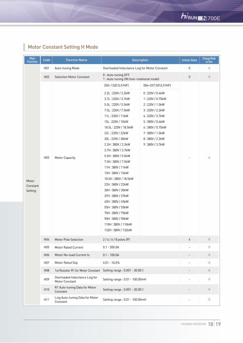
Motor Constant Setting H Mode
MainFunction
Motor Constant Setting
Description Initial Data Change Mode on RunFunction NameCode
H01 Auto-tuning Mode
Selection Motor Constant
Motor Pole Selection
Motor Rated Current
Motor No-load Current Io
Motor Rated Slip
1st Resistor R1 for Motor Constant
Overloaded Inductance Lsig for Motor Constant
Overloaded Inductance Lsig for Motor Constant
0 : Auto-tuning OFF1 : Auto-tuning ON (non-rotational mode)
055~1320 (LF/HF)
2.2L : 220V / 2.2kW
3.7L : 220V / 3.7kW
5.5L : 220V / 5.5kW
7.5L : 220V / 7.5kW
11L : 220V / 11kW
15L : 220V / 15kW
18.5L : 220V / 18.5kW
22L : 220V / 22kW
30L : 220V / 30kW
2.2H : 380V / 2.2kW
3.7H : 380V / 3.7kW
5.5H : 380V / 5.5kW
7.5H : 380V / 7.5kW
11H : 380V / 11kW
15H : 380V / 15kW
18.5H : 380V / 18.5kW
22H : 380V / 22kW
30H : 380V / 30kW
37H : 380V / 37kW
45H : 380V / 45kW
55H : 380V / 55kW
75H : 380V / 75kW
90H : 380V / 90kW
110H : 380V / 110kW
132H : 380V / 132kW
2 / 4 / 6 / 8 poles (P)
0.1 - 200.0A
0.1 - 100.0A
0.01 - 10.0%
Setting range : 0.001 - 30.00Ω
Setting range : 0.01 - 100.00mH
Setting range : 0.001 - 30.00Ω
Setting range : 0.01 - 100.00mH
004~037 (SF/LF/HF)
0 : 220V / 0.4kW
1 : 220V / 0.75kW
2 : 220V / 1.5kW
3 : 220V / 2.2kW
4 : 220V / 3.7kW
5 : 380V / 0.4kW
6 : 380V / 0.75kW
7 : 380V / 1.5kW
8 : 380V / 2.2kW
9 : 380V / 3.7kW
R1 Auto-tuning Data for Motor Constant
Lsig Auto-tuning Data for Motor Constant
Motor Capacity
H02
H04
H05
H06
H07
H08
H09
H10
H11
H03
0
0
-
X
X
X
4
-
-
-
-
-
-
-
X
X
X
X
X
X
X
X

ㅣTerminal Fuctionsㅣ
Explanation of Main Circuit Terminals
Explanation of Content
Connect input power.
Connect 3-phase motor.
After removing the short bar between PD and P, connect DC reactor for improvement of power factor.
Connect optional external braking resistor.
Grounding terminal.
Terminal Name
Main Power
Inverter Output
DC Reactor
External Braking Resistor
Inverter Earth Terminals
R, S, T (L1, L2, L3)
U, V, W (T1, T2, T3)
PD, P (+1, +)
P, RB (+, B+)
G
Symbol
Main Circuit Terminal Arrangement
Corresponding Type Screw Size Width(mm)Main Circuit Terminal Block
M4 10.6
N700E - 150LFN700E - 150HF
N700E - 185HFN700E - 220HF
N700E - 185LFN700E - 220LF
N700E - 015SFN700E - 022SF
N700E - 004SFN700E - 007SF
N700E - 004LFN700E - 007LFN700E - 015LF
N700E - 300HFN700E - 370HF
M5 13
M6 17
M6 17
M8 22
M8 29
M10
M10 x 2
30
26
N700E - 450HFN700E - 550HF
N700E - 750HFN700E - 900HF
N700E - 1100HFN700E - 1320HF
N700E-1600HF N700E-2200HFN700E-2800HF N700E-3500HF
N700E - 110LF M5 13
M3 7.62
M4 11
M4 11
M3 7.62
R(L1)
G G
S(L2)
T(L3)
P(+)
N(-)
PD(+1)
U(T1)
V(T2)
W(T3)
Short bar
R S T P URB V W
R S P URB V W
R S T P URB V W
R S P URB V W
R(L1)
G G
S(L2)
T(L3)
P(+) RBPD
(+1)U
(T1)V
(T2)W
(T3)
Short bar
R(L1)
G G
S(L2)
T(L3)
P(+) RBPD
(+1)U
(T1)V
(T2)W
(T3)
Short bar
R(L1)
G G
S(L2)
T(L3)
P(+) RBPD
(+1)U
(T1)V
(T2)W
(T3)
Short bar
G GShort bar
R(L1)
S(L2)
T(L3)
P(+) RBPD
(+1)U
(T1)V
(T2)W
(T3)
G G
N(-)
Short bar
R(L1)
S(L2)
T(L3)
P(+)
PD(+1)
U(T1)
V(T2)
W(T3)
G G
N(-)
Short bar
R(L1)
S(L2)
T(L3)
P(+)
PD(+1)
U(T1)
V(T2)
W(T3)
G G
N(-)
Short bar
R(L1)
S(L2)
T(L3)
P(+)
PD(+1)
U(T1)
V(T2)
W(T3)
G GShort bar
R(L1)
S(L2)
T(L3)
P(+)
N(-)
PD(+1)
U(T1)
V(T2)
W(T3)
N700E - 055LFN700E - 075LFN700E - 055HF
N700E - 075HFN700E - 110HF
N700E - 022LFN700E - 037LFN700E - 004HFN700E - 007HF
N700E - 015HFN700E - 022HFN700E - 037HF

HYUNDAI INVERTER 20 21
Control Terminal Arrangement
DOPRS485 RXP RXN CM1 CM1 P24 FM CM16 5 4 3 2 1 H O OI L LCM1 RN0 RN1 AL0 AL2AL1
CM1 5 4 2 1 P24 H O/OI L FM3 AL0 AL2AL1
DOPRS485 RXP RXN CM1 CM1 P24 FM CM16 5 4 3 2 1 H O OI L LCM1 RN0 RN1 AL0 AL2AL1
CM1 5 4 2 1 P24 H O/OI L FM3 AL0 AL2AL1 004~022SF, 004~037LF/HF
055~220LF / 055~3500HF
Explanation of Control Circuit Terminals
Explanation of Content
24VDC±10%, 35mA
Contact input : Close : On (run) Open : Off (stop)
Minimum on time: over 12ms
Analog frequency meter
10VDC
0~10VDC, input impedance 10Ω
4~20mA, input impedance 210Ω
Rated value for contact :AC 250V 2.5A (resisitive load) 0.2A (Induced load) DC 30V 3.0A (resisitive load) 0.7A (induced load)
Rated value for contact : AC 250V 2.5A (resisitive load) 0.2A (induced load) DC 30V 3.0A (resisitive load) 0.7A (induced load)
Terminal Name
Power Terminal for Input Signal
Intelligent Input Terminal :Forward Direction (FW), Reverse Direction (RV), Multi-speed 1-4 (CF1-4), 2-Level Accel/Decel Command (2CH), Reset (RS), Free-run Stop (FRS), External Trip (EXT), Soft Lock (SFT), Jogging Run (JG), Unattended Start Protection (USP) 2), Analog Input Voltage / Current Transferring (AT)
Common Terminal for Input or Monitor Signal
Output Frequency Meter, Output Current Meter, Output Voltage Meter
Power Supply for Frequency Command
Voltage Frequency Command Terminal
Current Frequency Command Terminal
Common Terminal for Frequency Command
Intelligent Output Terminal :Running Signal (RUN), Frequency Arrival Signal (at the set frequency) (FA1), Frequency Arrival Signal (at or above the set frequency) (FA2), Overload Advanced Notice Signal (OL), Output Deviation of PID Signal (OD), Alarm Signal (AL)
Alarm Output Signal : at Normal Operation, Power Off (Initial Condition) : AL0-AL2 Closed at Abnormal : AL0-AL1 Closed
Input Signal 1)
Monitor Signal
Frequency Setup Signal
Output Signal 3)
Trip Alarm Output Signal 4)
Signal Symbol
P24
6 (RS)
5 (AT)
4 (CF2)
3 (CF1)
2 (RV)
1 (FW)
CM1
FM
H
O
OI
L
RN0 RN1
AL0 AL1 AL2
※ 1) Input signal terminals from 1 to 6 are contact “a”s. When you want to change those terminals to contact “b”s, configuration should be set in C07~C12
2) USP: Protects inverter from restarting when power supply is on.
3) Intelligent relay output terminal RN is “a” contact. When you use RN as “b” contact, please set it to C14.
4) Operator can select ‘pre-warning alarm for overload’ and ‘arrival to the predefined frequency’ signals with the intelligent output terminal.
ㅣConnecting Diagramㅣ
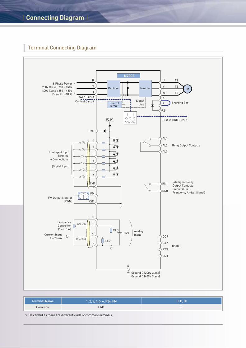
Terminal Connecting Diagram
※ Be careful as there are different kinds of common terminals.
R
S
T
PD
P
2
3
G
Control Circuit
N700E
Rectifier Inverter
Power Circuit
1
4
5
6
CM1
CM1
H
O
OI
FM
3-Phase Power200V Class : 200 ~ 240V400V Class : 380 ~ 480V
(50/60Hz ±10%)
Intelligent InputTerminal
(6 Connections)
(Digital Input)
FM Output Monitor(PWM)
FrequencyController (1kΩ, 1W)
Current Input4 ~ 20mA
DC 0 ~ 10V
DC 4 ~ 20mA
SignalLineControl
Circuit
P24V
U
V
W
T1
T2
T3
Shorting Bar
Buit-in BRD Circuit
IM
P24
RB
AL1
AL2
AL0
Relay Output Contacts
Intelligent RelayOutput Contacts(Initial Value : Frequency Arrival Signal)
RS485
RN1
RN0
DOP
RXP
RXN
CM1
AnalogInput
P12V10kΩ
200ΩL
Ground D (200V Class)Ground C (400V Class)
Terminal Name
Common
1, 2, 3, 4, 5, 6, P24, FM
CM1
H, O, OI
L

ㅣConnection to PLCㅣ
Using Interface Power Inside Inverter Sink Type Source Type
Using External Power Sink Type Source Type
Connection with Input Terminals
Sink Type Source Type
Connection with Output Terminals
SS
S
1
8
8
P24
PLC DC 24V
InverterOutput Module
InverterOutput Module
COM
Short
Short
CM1
P24
PLC
CM1
FW
DC 24V
InverterOutput Module
8
8
S
1
P24
PLC DC 24V
DC 24VCOM
COM
CM1
FW
P24
PLC
CM1DC 24V
DC 24V
InverterOutput Module
DC 24V
PLCInverter
CM2
COM
12
11
PLCInverter
12
11
CM2
DC 24VCOM
SS
S
1
8
8
P24
PLC DC 24V
InverterOutput Module
InverterOutput Module
COM
Short
Short
CM1
P24
PLC
CM1
FW
DC 24V
InverterOutput Module
8
8
S
1
P24
PLC DC 24V
DC 24VCOM
COM
CM1
FW
P24
PLC
CM1DC 24V
DC 24V
InverterOutput Module
DC 24V
PLCInverter
CM2
COM
12
11
PLCInverter
12
11
CM2
DC 24VCOM
SS
S
1
8
8
P24
PLC DC 24V
InverterOutput Module
InverterOutput Module
COM
Short
Short
CM1
P24
PLC
CM1
FW
DC 24V
InverterOutput Module
8
8
S
1
P24
PLC DC 24V
DC 24VCOM
COM
CM1
FW
P24
PLC
CM1DC 24V
DC 24V
InverterOutput Module
DC 24V
PLCInverter
CM2
COM
12
11
PLCInverter
12
11
CM2
DC 24VCOM
SS
S
1
8
8
P24
PLC DC 24V
InverterOutput Module
InverterOutput Module
COM
Short
Short
CM1
P24
PLC
CM1
FW
DC 24V
InverterOutput Module
8
8
S
1
P24
PLC DC 24V
DC 24VCOM
COM
CM1
FW
P24
PLC
CM1DC 24V
DC 24V
InverterOutput Module
DC 24V
PLCInverter
CM2
COM
12
11
PLCInverter
12
11
CM2
DC 24VCOM
SS
S
1
8
8
P24
PLC DC 24V
InverterOutput Module
InverterOutput Module
COM
Short
Short
CM1
P24
PLC
CM1
FW
DC 24V
InverterOutput Module
8
8
S
1
P24
PLC DC 24V
DC 24VCOM
COM
CM1
FW
P24
PLC
CM1DC 24V
DC 24V
InverterOutput Module
DC 24V
PLCInverter
CM2
COM
12
11
PLCInverter
12
11
CM2
DC 24VCOM
SS
S
1
8
8
P24
PLC DC 24V
InverterOutput Module
InverterOutput Module
COM
Short
Short
CM1
P24
PLC
CM1
FW
DC 24V
InverterOutput Module
8
8
S
1
P24
PLC DC 24V
DC 24VCOM
COM
CM1
FW
P24
PLC
CM1DC 24V
DC 24V
InverterOutput Module
DC 24V
PLCInverter
CM2
COM
12
11
PLCInverter
12
11
CM2
DC 24VCOM
※ Be sure to turn on the inverters after turning on the PLC and its external power source to prevent the parameters in the inverter from being modified.
HYUNDAI INVERTER 22 23
ㅣProtective Functionsㅣ
Display on Digital Operator
E04
E05
E07
E60
E09
E04 or E34
E13
E08
E12
E21
E14
E17
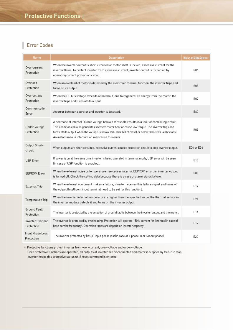
Description
When the inverter output is short circuited or motor shaft is locked, excessive current for the
inverter flows. To protect inverter from excessive current, inverter output is turned off by
operating current protection circuit.
When an overload of motor is detected by the electronic thermal function, the inverter trips and
turns off its output.
When the DC bus voltage exceeds a threshold, due to regenerative energy from the motor, the
inverter trips and turns off its output.
An error between operator and inverter is detected.
A decrease of internal DC bus voltage below a threshold results in a fault of controlling circuit.
This condition can also generate excessive motor heat or cause low torque. The inverter trips and
turns off its output when the voltage is below 150~160V (200V class) or below 300~320V (400V class)
An instantaneous interruption may cause this error.
When outputs are short circuited, excessive current causes protection circuit to stop inverter output.
If power is on at the same time inverter is being operated in terminal mode, USP error will be seen
(in case of USP function is enabled).
When the external noise or temperature rise causes internal EEPROM error, an inverter output
is turned off. Check the setting data because there is a case of alarm signal failure.
When the external equipment makes a failure, inverter receives this failure signal and turns off
the output (Intelligent input terminal need to be set for this function).
When the inverter internal temperature is higher than the specified value, the thermal sensor in
the inverter module detects it and turns off the inverter output.
The inverter is protected by the detection of ground faults between the inverter output and the motor.
The Inverter is protected by overheating. Protection will operate 150% current for 1minute(In case of
base carrier frequency). Operation times are depend on inverter capacity.
Over-current
Protection
Overload
Protection
Over-voltage
Protection
Communication
Error
Under-voltage
Protection
Output Short-
circuit
USP Error
EEPROM Error
External Trip
Temperature Trip
Ground Fault
Protection
Inverter Overload
Protection
Error Codes
※ Protective functions protect inverter from over-current, over-voltage and under-voltage. Once protective functions are operated, all outputs of inverter are disconnected and motor is stopped by free-run stop. Inverter keeps this protective status until reset command is entered.
Name
Input Phase Loss
Protection E20The inverter protected by (R,S,T) input phase loss(in case of 1-phase, R or S input phase).

Common Applicable Tools
ㅣWiring and Optionsㅣ
HYUNDAI INVERTER 24 25
0.4
0.4
0.75
0.75
1.5
1.5
2.2
2.2
3.7
5.5
7.5
11
15
18.5
22
0.4
0.75
1.5
2.2
3.7
5.5
7.5
11
15
18.5
22
30
37
45
55
75
90
110
132
160
220
280
350
N700E-004SF
N700E-004LF
N700E-007SF
N700E-007LF
N700E-015SF
N700E-015LF
N700E-022SF
N700E-022LF
N700E-037LF
N700E-055LF
N700E-075LF
N700E-110LF
N700E-150LF
N700E-185LF
N700E-220LF
N700E-004HF
N700E-007HF
N700E-015HF
N700E-022HF
N700E-037HF
N700E-055HF
N700E-075HF
N700E-110HF
N700E-150HF
N700E-185HF
N700E-220HF
N700E-300HF
N700E-370HF
N700E-450HF
N700E-550HF
N700E-750HF
N700E-900HF
N700E-1100HF
N700E-1320HF
N700E-1600HF
N700E-2200HF
N700E-2800HF
N700E-3500HF
More than 1.25
More than 1.25
More than 1.25
More than 1.25
More than 2
More than 2
More than 2
More than 2
More than 3.5
More than 6
More than 10
More than 16
More than 25
More than 30
More than 35
More than 1.25
More than 1.25
More than 1.25
More than 1.25
More than 2
More than 4
More than 4
More than 6
More than 10
More than 16
More than 25
More than 25
More than 35
More than 35
More than 70
More than 35x2
More than 35x2
More than 50x2
More than 80x2
More than 0x2
More than 100x2
More than 150x2
More than 200x2
-
-
-
-
-
-
-
-
-
6
6
6
16
16
16
-
-
-
-
-
4
4
6
10
10
10
-
-
-
-
-
-
-
-
-
-
-
-
M3
M3
M3
M3
M4
M3
M4
M4
M4
M4
M4
M5
M5
M6
M6
M4
M4
M4
M4
M4
M4
M4
M4
M5
M5
M5
M6
M6
M8
M8
M8
M8
M10
M10
M13
M13
M13
M13
0.5
0.5
0.5
0.5
1.2
0.5
1.2
1.2
1.2
1.2
1.2
3.0
3.0
4.5
4.5
1.2
1.2
1.2
1.2
1.2
1.2
1.2
1.2
3.0
3.0
3.0
4.5
4.5
6.0
6.0
6.0
6.0
10.0
10.0
12
12
12
12
5A
5A
10A
10A
15A
15A
20A
20A
30A
50A
50A
75A
100A
150A
150A
5A
5A
10A
10A
15A
30A
30A
50A
50A
75A
75A
100A
100A
150A
175A
225A
225A
350A
350A
700A
800A
1000A
1200A
HBS-33
HBS-33
HBS-33
HBS-33
HBS-33
HBS-33
HBS-33
HBS-33
HBS-33
HBS60N
HBS60N
HBS100N
HBS100N
HBS225N
HBS225N
HBS-33
HBS-33
HBS-33
HBS-33
HBS-33
HBS30N
HBS30N
HBS60N
HBS100N
HBS100N
HBS100N
HBS100N
HBS225N
HBS225N
HBS225N
HBS400N
HBS400N
HBS400N
HBS400N
HiBS800
HiBS800
HiBS1000
HiBS1200
HiMC10W
HiMC10W
HiMC10W
HiMC10W
HiMC10W
HiMC10W
HiMC20W
HiMC20W
HiMC20W
HiMC32
HiMC32
HiMC50
HiMC65
HiMC80
HiMC110
HiMC10W
HiMC10W
HiMC10W
HiMC10W
HiMC20W
HiMC18
HiMC18
HiMC32
HiMC40
HiMC40
HiMC50
HiMC65
HiMC80
HiMC110
HiMC130
HiMC180
HiMC220
HiMC260
HiMC300
HiMC400
HiMC500
HiMC630
HiMC800
200VClass
400VClass
ClassMotorOutput(kW)
InverterModel
Power Cable (mm2) 1)
R,S,T,U,V,W,PD,P
External Resistorbetween
P and RB (mm2)
Applicable ToolsScrew Sizeof Terminal
Torque(N•m) Circuit Breaker
(MCCB)Magnetic
Contactor (MC)
※ 1) Use 600V, 75°C copper wire.
ㅣWiring and Optionsㅣ
Digital Operator (DOP7)
Keys Example
POWER RUN
RUN
FUNC STRUP DN
MIN. MAX.
STOPRESET
PRG
A Hz
Layout and Specification
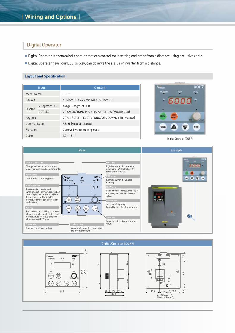
Index Content
DOP7
67.5 mm (H) X 64.9 mm (W) X 35.1 mm (D)
4-digit 7-segment LED
7 (POWER / RUN / PRG / Hz / A / RUN key / Volume LED)
7 (RUN / STOP (RESET) / FUNC / UP / DOWN / STR / Volume)
RS485 (Modular Method)
Observe inverter running state
1.5 m, 3 m
Model Name
Lay-out
Display
Key-pad
Communication
Function
Cable
7-segment LED
DOT LED
64.9
64.9
2.5
67.5
27.7
24
37.2
41
158.5 11.635.1 2-M3 Taps
Mount'g holes
1425.4 5.9
46.5
23.5
0.8
12.4
21.8
17
18
Digital Operater (DOP7)
Digital Operator
Digital Operater is economical operater that can control main setting and order from a distance using exclusive cable.
Digital Operater have four LED display, can observe the status of inverter from a distance.
Display (LED signal)
Displays frequency, motor current, motor rotational number, alarm setting
Run lamp
Light is on when the inverter is generating PWM output or RUN command is entered.
PRG lamp
Light is on when the value is entering
Hz/A lamp
Show whether the displayed data is frequency value or data current value.
Volume key
Set output frequency.(available only when the lamp is on)
Store key
Store the selected data or the set value.Function key
Command selecting function.
Up/Down key
Increase/decrease frequency value, and modify set values
Stop/Reset key
Stop operating inverter and cancellation of alarm(available in both sides of operator and terminal) When the inverter is run through b15 terminal, operator can select valid or invalid state.
Power lamp
Lamp for the controlling power
Run key
Run the inverter. RUN key is disabled when the inverter is selected to run by terminal. RUN key is available only while the above LED is on.

Wiring and Options
Three PhasePower Supply
MCCB
MC
( 1 )
( 2 )
( 3 )
( 4 )
( 5 )
( 6 )
( 7 )
( 8, 9 )
Motor
R S TPD
P
RB
U V
Inverter
W
Wiringandoptions Wiring Distance
Under 100m
Under 300m
Sensitive Current(mA)50
100
DescriptionFunction NameOrder
The sensitivity of circuit breaker (MCCB) should be differentiated by the sums of wiring distances (inverter-power supply and inverter-motor).
※ Applied wiring equipment represents HYUNDAI 3-phase 4-poles motor. ※ Braking capacity should be considered for circuit breaker. ※ When wiring distance is over 20m, there is need to apply large power cable. ※ Use circuit breaker (MCCB) for safety.※ Do not perform ON/OFF function of electromagnetic contactor while inverter
is in normal operating condition. ※ Use 0.75mm2 for alarm output contact. ※ When wiring with metal tube using CV line, there exists 30mA/km current.※ IV line has high non-dielectric constant : current increases 8 times.
Therefore, 8 times greater sensitivity current , as shown in the table above, should be applied. When wiring distance is over 100m, use CV line.
※ ON/OFF operation is prohibited at the output side by using electromagnetic contactor. when it is necessary to apply electromagnetic contactor at the output side by using bypass circuit, protective circuit that prevents electromagnetic contactor from operating ON/OFF function should be applied while inverter is in normal operation.
(1)
(2)
(3)
(4)
(5)
(6)
(7)
(8)
(9)
Input-side AC Reactor
(Harmonic Control, Electrical Coordination, Power-factor Improvement)
Noise Filter for Inverter
Radio Noise Filter
(Zero-phase Reactor)
Input Radio Noise Filter
DC Reactor
Output-side Noise Filter
Radio Noise Filter
(0-phase Reactor)
Output AC Reactor to Reduce Vibration and Prevent Thermal Relay Misapplication
LCR Filter
As a measure of suppressing harmonics induced on the power supply lines, it is applied when imbalance of the main power voltage exceeds 3% (and power source capacity is more than 500kVA), or when the power voltage is rapidly changed. It also improves the power factor.
This reduces common noise that is generated between input power and ground. Connect this filter to 1st side (input side) of inverter.
Electrical noise interference may occur on nearby equipment such as a radio receiver. This magnetic choke filter helps reduce radiated noise (can also be used on output).
This reduces radiated noise from Input power wirings.
Suppresses harmonics generated by the inverter
This reduces radiated noise from wiring in the inverter output side. This also reduces wave fault to radio and TV, and it is used for preventing malfunction of sensor and measuring instruments.
Electrical noise interference may occur on nearby equipment such as a radio receiver. This magnetic choke filter helps reduce radiated noise (can also be used on input).
This reactor reduces the vibration in the motor caused by the inverter’s switching waveforms, by smoothing the waveforms to approximate commercial power quality. When wiring from the inverter to the motor is more than 10m in length, inserting a reactor prevents thermal relay’s malfunction by harmonic generated by inverter’s high switching.
Sine-wave shaping filter for the output side.
HYUNDAI INVERTER 26 27

ㅣWiring and Optionsㅣ
Input Reactor Specification
InverterAC Reactor Model(High Harmonics)
Size(mm)
ExFGD1DCBWHDrawingWeight
(kg)Inductance
(mH)Current
(A)
200V
ACL-LI-1.5 (ACL-LI5-1.5) 004SF/LF 5.5 1.16 (2.91) 95 (130) 100 (155) 65 (125) 60 (72) 95 (110) 75 (92) 30 (33.5) 5Ф 1.5 (2.5) A (A)
ACL-LI-2.5 (ACL-LI5-2.5) 007SF/LF 8.2 0.78 (1.95) 130 (130) 155 (155) 125 (125) 72 (72) 110 (110) 92 (92) 30 (33.5) 7x20 2.5 (3.5) A (A)
ACL-LI-3.5 (ACL-LI5-3.5) 015~022SF/LF 11.5 0.56 (1.39) 130 (145) 155 (155) 125 (125) 72 (75) 110 (120) 92 (95) 30 (30) 7x20 2.5 (4.5) A (A)
ACL-LI-5.5 (ACL-LI5-5.5) 037LF 18 0.36 (0.89) 130 (145) 155 (155) 125 (125) 72 (75) 110 (120) 92 (95) 30 (30) 7x20 3 (5.5) A (A)
ACL-LI-7.5 (ACL-LI5-7.5) 055LF 26.5 0.24 (0.60) 130 (145) 155 (155) 65 (125) 82 (75) 120 (120) 102 (95) 30 (30) 7x20 4 (6) A (A)
ACL-LI-11 (ACL-LI5-11) 075LF 35 0.18 (0.46) 145 (145) 155 (155) 125 (125) 75 (85) 120 (125) 95 (105) 30 (30) 7x20 6 (7.5) A (A)
ACL-LI-15 (ACL-LI5-15) 110LF 50.5 0.13 (0.32) 145 (150) 155 (180) 125 (155) 75 (80) 120 (-) 95 (100) 30 (30) 7x20 6 (9) A (B)
ACL-LI-22 (ACL-LI5-22) 150LF 70.5 0.09 (0.23) 190 (150) 240 (180) 125 (155) 93 (105) 145 (-) 113 (125) 30 (30) 9x20 15 (14) C (B)
ACL-LI-33 (ACL-LI5-33) 185~220LF 105 0.06 (0.15) 220 (150) 240 (180) 125 (155) 93 (105) 145 (-) 113 (125) 30 (30) 9x20 16 (16) C (B)
400V
ACL-HI-1.5 (ACL-HI5-1.5) 004~007HF 4 3.2 (8) 125 (140) 150 (150) 120 (120) 70 (70) 105 (110) 90 (95) 33.5 (30) 7x20 1.5 (3.5) A (A)
ACL-HI-2.5 (ACL-HI5-2.5) 015HF 5 2.5 (6.5) 125 (140) 150 (150) 120 (120) 70 (70) 105 (110) 90 (95) 33.5 (30) 7x20 2 (4) A (A)
ACL-HI-3.5 (ACL-HI5-3.5) 022HF 8 1.6 (4) 125 (140) 150 (150) 120 (120) 70 (70) 105 (110) 90 (95) 33.5 (30) 7x20 2.5 (4.5) A (A)
ACL-HI-5.5 (ACL-HI5-6.5) 037HF 9 1.42 (3.56) 130 (145) 155 (155) 125 (125) 72 (75) 110 (115) 92 (95) 33.5 (30) 7x20 3 (5) A (A)
ACL-HI-7.5 (ACL-HI5-8) 055HF 14.5 0.88 (2.21) 130 (145) 155 (155) 125 (125) 72 (75) 110 (115) 92 (95) 33.5 (30) 7x20 3.5 (5.5) A (A)
ACL-HI-11 (ACL-HI5-11) 075HF 17.5 0.73 (1.83) 145 (145) 155 (155) 125 (125) 75 (85) 120 (125) 95 (105) 30 (30) 7x20 4.5 (7) A (A)
ACL-HI-15 (ACL-HI5-16) 110HF 25 0.51 (1.28) 145 (145) 155 (155) 125 (125) 75 (85) 120 (125) 95 (105) 30 (30) 7x20 5.5 (7.5) A (A)
ACL-HI-22 (ACL-HI5-22) 150HF 35 0.37 (0.91) 145 (170) 155 (180) 125 (155) 85 (80) 130 (120) 105 (100) 30 (30) 7x20 6.5 (10) A (A)
ACL-HI-33 (ACL-HI5-33) 185~220HF 52 0.25 (0.62) 150 (150) 180 (180) 155 (155) 80 (100) - (-) 100 (120) 30 (30) 7x20 8.5 (14) B (B)
ACL-HI-40 (ACL-HI5-40) 300HF 63 0.2 (0.51) 150 (180) 180 (240) 155 (100) 80 (103) - (165) 100 (123) 30 (30) 7x20 9.5 (20) B (C)
ACL-HI-50 (ACL-HI5-50) 370HF 80 0.16 (0.4) 200 (210) 240 (280) 100 (100) 98 (108) 150 (165) 118 (128) 30 (30) 9x20 17 (22) C (C)
ACL-HI-60 (ACL-HI5-60) 450HF 99 0.13 (0.32) 210 (220) 240 (280) 100 (100) 98 (98) 150 (165) 118 (118) 30 (30) 9x20 18 (23) C (C)
ACL-HI-70 (ACL-HI5-70) 550HF 120 0.11 (0.27) 230 (230) 240 (290) 125 (125) 113 (113) 160 (170) 133 (133) 35 (35) 9x20 22 (28) C (C)
ACL-HI-100 (ACL-HI5-100) 750HF 165 0.08 (0.19) 230 (260) 240 (280) 125 (125) 113 (113) 160 (175) 133 (133) 35 (30) 9x20 24 (33) C (C)
ACL-HI-120 (ACL-HI5-120) 900HF 193 0.07 (0.17) 230 (230) 240 (290) 125 (125) 123 (123) 170 (185) 143 (143) 40 (30) 9x20 25 (37) C (C)
ACL-HI-150 (ACL-HI5-150) 1100HF 235 0.05 (0.14) 230 (250) 240 (320) 125 (125) 143 (143) 180 (195) 163 (163) 50 (40) 9x20 26 (45) C (C)
ACL-HI-180 (ACL-HI5-180) 1320HF 285 0.04 (0.11) 270 (270) 290 (320) 125 (125) 143 (143) 190 (200) 163 (163) 50 (45) 9x20 33 (48) C (C)
ACL-HI-220 (ACL-HI5-200) 1600HF 358 0.04 (0.09) 300 (320) 290 (350) 125 (125) 133 (133) 190 (200) 153 (153) 40 (40) 11 x 20 40 (60) C (C)
ACL-HI-300 (ACL-HI5-300) 2200HF 494 0.03 (0.06) 300 (300) 300 (350) 125 (125) 138 (138) 200 (205) 158 (158) 40 (40) 11 x 20 50 (67) C (C)
ACL-HI-400 (ACL-HI5-400) 2800HF 578 0.02 (0.06) 300 (310) 300 (360) 125 (125) 158 (166) 215 (250) 178 (186) 50 (35) 11 x 20 58 (90) C (C)
ACL-HI-500 (ACL-HI5-500) 3500HF 720 0.018 (0.044) 300 (380) 300 (420) 125 (125) 158 (166) 215 (250) 178 (186) 50 (45) 11 x 20 75 (120) C (C)H
W
D1
E
FG
B
C
W
D1
G
E
F
B
CH
30
H
D
W
D1
GF
B
60
35
20
C
E
Drawing
Input/Output AC Reactor
A TYPE B TYPE C TYPE
Size(mm)

HYUNDAI INVERTER 28 29
Input Reactor Specification
ExFGD1DCBWH
Wiring
Input/Output AC Reactor
R0
S0
T0
R
S
T
R
S
T
U
MV
W
source
Reactor InverterMotor
R
S
T
M
UU
V
W
V
W
X
Y
Z
ReactorMotor
Inverter
source
H
D
W
D1
G
E
F
B
6035
20
C
W
D1
G
E
F
B
C
H
30
D
H
W
D1
E
FG
B
C
R0
S0
T0
ACL- I-
ACL- I-
R
S
T
R
S
T
R
S
T
U
M
M
V
W
UU
V
W
V
W
X
Y
Z
전원
리액터
리액터
인버터모터
모터
(입력측)
(출력측)
인버터
전원
H
D
W
D1
G
E
F
B
60
35
20
C
W
D1
G
E
F
B
C
H
30
HD
W
D1
EF
G
B
C
R0
S0
T0
R
S
T
R
S
T
U
MV
W
source
Reactor InverterMotor
R
S
T
M
UU
V
W
V
W
X
Y
Z
ReactorMotor
Inverter
source
H
D
W
D1
G
E
F
B
60
35
20
C
W
D1
G
E
F
BC
H
30
D
H
W
D1
E
FG
B
C
R0
S0
T0
ACL- I-
ACL- I-
R
S
T
R
S
T
R
S
T
U
M
M
V
W
UU
V
W
V
W
X
Y
Z
전원
리액터
리액터
인버터모터
모터
(입력측)
(출력측)
인버터
전원
H
D
W
D1
G
E
F
B
60
35
20
C
W
D1
G
E
F
B
C
H
30
H
D
W
D1
E
FG
B
C
Input Input AC Reactor
200V
ACL-L-0.4 004SF/LF 3 1.5 130 155 125 72 105 92 33.5 7x20 2.5 A
ACL-L-0.75 007SF/LF 4.2 1.2 130 155 125 72 105 92 33.5 7x20 2.5 A
ACL-L-1.5 015SF/LF 7.5 0.67 130 155 125 72 105 92 33.5 7x20 3 A
ACL-L-2.2 022SF/LF 10.5 0.41 130 155 125 72 105 92 33.5 7x20 3 A
ACL-L-3.7 037LF 16 0.25 130 155 125 72 105 92 33.5 7x20 3.5 A
ACL-L-5.5 055LF 22 0.18 145 155 125 85 125 105 30 7x20 5 A
ACL-L-7.5 075LF 32 0.12 145 155 125 85 125 105 30 7x20 6 A
ACL-L-11 110LF 43 0.09 145 155 125 85 125 105 30 7x20 7 A
ACL-L-15 150LF 64 0.06 150 180 155 80 - 100 30 7x20 7.5 B
ACL-L-18.5 185LF 80 0.05 150 180 155 80 - 100 30 7x20 8 B
ACL-L-22 220LF 95 0.042 150 180 155 80 - 100 30 7x20 8 B
400V
ACL-H-1.5 004~015HF 3.8 2.12 130 155 125 72 110 92 33.5 7x20 2.5 A
ACL-H-2.2 022HF 5.3 1.52 130 155 125 72 110 92 33.5 7x20 3 A
ACL-H-3.7 037HF 8 1.01 130 155 125 72 110 92 33.5 7x20 3.5 A
ACL-H-5.5 055HF 11 0.73 145 155 125 85 125 105 30 7x20 6 A
ACL-H-7.5 075HF 16 0.58 145 155 125 85 125 105 30 7x20 6.5 A
ACL-H-11 110HF 22 0.31 145 155 125 85 125 105 30 7x20 6.5 A
ACL-H-15 150HF 32 0.25 145 155 125 85 125 105 30 7x20 7 A
ACL-H-18.5 185HF 40 0.2 150 180 155 80 - 100 30 7x20 8.5 B
ACL-H-22 220HF 48 0.16 150 180 155 80 - 100 30 7x20 9 B
ACL-H-30 300HF 58 0.13 150 180 155 80 - 100 30 7x20 9.5 B
ACL-H-37 370HF 72 0.11 150 180 155 105 - 125 30 7x20 11 B
ACL-H-45 450HF 87 0.092 150 180 155 105 - 125 30 7x20 12 B
ACL-H-55 550HF 101 0.08 190 240 155 103 - 123 30 7x20 16 B
ACL-H-75 750HF 144 0.056 220 280 155 103 150 123 30 9x20 24 C
ACL-H-90 900HF 173 0.046 240 300 155 103 150 123 30 9x20 28 C
ACL-H-110 1100HF 217 0.037 260 310 155 123 170 143 40 11x20 32 C
ACL-H-132 1320HF 260 0.031 280 310 155 123 170 143 40 11x20 36 C
ACL-H-160 1600HF 300 0.024 260 320 290 123 185 143 40 11 x 20 38 C
ACL-H-220 2200HF 415 0.018 290 350 290 143 210 163 50 11 x 20 45 C
ACL-H-280 2800HF 525 0.015 310 350 290 153 220 173 50 11 x 20 57 C
ACL-H-375 3500HF 690 0.02
InverterAC Reactor Model(High Harmonics)
Size(mm)DrawingWeight
(kg)Inductance
(mH)Current
(A)
Output Output AC Reactor

ㅣWiring and Optionsㅣ
Drawing Wiring
Inverter Noise Filter
2-Ø5
2-Ø74-Ø7
T-Ø30G-M10x30
2-Ø7
T-M6
T-M12
G-M8
T-M12
180196
W-210W-239
15
12
2020
120
3535
1296
H-1
20
D-70
2525
130
H-1
80D-
125
G-M6
1525 25230
SHIELD BOX
MCCBR1S1T1
RST
UVW
R2S2T2
R1S1T1
U
R+ R-
V W
R2S2T2
SHIELD TUBE
180
B
H-1
60 C
D-10
0
G-M6
230266
W-280X-348
370
400430
X-461
W-43015151515
382
320358.5W-382X-438
31 31320
D
4560
6045 25
2550
5060
H-2
10E
D-15
0
InputNoise Filter
OutputNoise FilterInverter
Motor
MicroSurge Filter
Resistor
Source
2-Ø5
2-Ø74-Ø7
T-Ø30G-M10x30
2-Ø7
T-M6
T-M12
G-M8
T-M12
180196
W-210W-239
15
12
2020
120
3535
1296
H-1
20
D-70
2525
130
H-1
80D-
125
G-M6
1525 25230
SHIELD BOX
MCCBR1S1T1
RST
UVW
R2S2T2
R1S1T1
U
R+ R-
V W
R2S2T2
SHIELD TUBE
180
B
H-1
60 C
D-10
0
G-M6
230266
W-280X-348
370
400430
X-461
W-43015151515
382
320358.5W-382X-438
31 31320
D
4560
6045 25
2550
5060
H-2
10E
D-15
0Input
Noise FilterOutput
Noise FilterInverterMotor
MicroSurge Filter
Resistor
Source
Input Noise Filter Specification Output Noise Filter Specification
Model Model NameSpecification
G TSize [W x H x D.X(mm)]
RatedCurrent
(A)Drawing
200V
055LF 24 FT-20301S-A 250 30 210x120x70 · 239 M6 M6 B
075LF 32 FT-20401S-A 250 40 210x120x70 · 239 M6 M6 B
110LF 46 FT-20501S-A 250 50 210x120x70 · 239 M6 M6 B
150LF 64 FT-20701S-A 250 70 280x160x100 · 348 M6 M12 C
185LF 76 FT-20801S-A 250 80 280x160x100 · 348 M6 M12 C
220LF 95 FT-21001S-A 250 100 382x180x125 · 438 M8 M12 D
300LF 121 FT-21301S-A 250 130 382x180x125 · 438 M8 M12 D
370LF 145 FT-21501S-A 250 150 430x210x150 · 461 M10 M10 E
450LF 182 FT-22001S-A 250 200 430x210x150 · 461 M10 M10 E
550LF 220 FT-22501S-A 250 250 430x210x150 · 461 M10 M10 E
400V
055HF 12 FT-40201S-A 450 20 210x120x70 · 239 M6 M6 B
075HF 16 FT-40201S-A 450 20 210x120x70 · 239 M6 M6 B
110HF 23 FT-40301S-A 450 30 210x120x70 · 239 M6 M6 B
150HF 32 FT-40401S-A 450 40 210x120x70 · 239 M6 M6 B
185HF 38 FT-40401S-A 450 40 210x120x70 · 239 M6 M6 B
220HF 48 FT-40501S-A 450 50 210x120x70 · 239 M6 M6 B
300HF 58 FT-40601S-A 450 60 210x120x70 · 239 M6 M6 B
370HF 75 FT-40801S-A 450 80 280x160x100 · 348 M6 M12 C
450HF 90 FT-41001S-A 450 100 382x180x125 · 438 M8 M12 D
550HF 110 FT-41201S-A 450 120 382x180x125 · 438 M8 M12 D
750HF 149 FT-41501S-A 450 150 430x210x150 · 461 M10 M10 E
900HF 176 FT-41801S-A 450 180 430x210x150 · 461 M10 M10 E
1100HF 217 FT-42201S-A 450 220 430x210x150 · 461 M10 M10 E
1320HF 260 FT-42601S-A 450 260 430x210x150 · 461 M10 M10 E
1600HF 300 KT-3AK-4400 450 400 475x200x220 M12 M12
2200HF 415 KT-3AK-5500 450 500 510x200x220 M12 M12
2800HF 525 A3R4700-KL 450 700 520x160x220 8x12 M8x30
3500HF 656 A3R41K0-KL 450 1000 520x160x220 8x12 M8x30
G T
200V
055LF 24 FT-20301SO-A 250 30 210x120x70 · 239 M6 M6 B
075LF 32 FT-20401SO-A 250 40 210x120x70 · 239 M6 M6 B
110LF 46 FT-20501SO-A 250 50 210x120x70 · 239 M6 M6 B
150LF 64 FT-20701SO-A 250 70 280x160x100 · 348 M6 M12 C
185LF 76 FT-20801SO-A 250 80 280x160x100 · 348 M6 M12 C
220LF 95 FT-21001SO-A 250 100 382x180x125 · 438 M8 M12 D
300LF 121 FT-21301SO-A 250 130 382x180x125 · 438 M8 M12 D
370LF 145 FT-21501SO-A 250 150 430x210x150 · 461 M10 M10 E
450LF 182 FT-22001SO-A 250 200 430x210x150 · 461 M10 M10 E
550LF 220 FT-22501SO-A 250 250 430x210x150 · 461 M10 M10 E
400V
055HF 12 FT-40201SO-A 450 20 210x120x70 · 239 M6 M6 B
075HF 16 FT-40201SO-A 450 20 210x120x70 · 239 M6 M6 B
110HF 23 FT-40301SO-A 450 30 210x120x70 · 239 M6 M6 B
150HF 32 FT-40401SO-A 450 40 210x120x70 · 239 M6 M6 B
185HF 38 FT-40401SO-A 450 40 210x120x70 · 239 M6 M6 B
220HF 48 FT-40501SO-A 450 50 210x120x70 · 239 M6 M6 B
300HF 58 FT-40601SO-A 450 60 210x120x70 · 239 M6 M6 B
370HF 75 FT-40801SO-A 450 80 280x160x100 · 348 M6 M12 C
450HF 90 FT-41001SO-A 450 100 382x180x125 · 438 M8 M12 D
550HF 110 FT-41201SO-A 450 120 382x180x125 · 438 M8 M12 D
750HF 149 FT-41501SO-A 450 150 430x210x150 · 461 M10 M10 E
900HF 176 FT-41801SO-A 450 180 430x210x150 · 461 M10 M10 E
1100HF 217 FT-42201SO-A 450 220 430x210x150 · 461 M10 M10 E
1320HF 260 FT-42601SO-A 450 260 430x210x150 · 461 M10 M10 E
1600HF 300 KT-3AK-4400 450 400 475x200x220 M12 M12
2200HF 415 KT-3AK-5500 450 500 510x200x220 M12 M12
2800HF 525 A3R4700-KL 450 700 520x160x220 8x12 M8x30
3500HF 656 A3R41K0-KL 450 1000 520x160x220 8x12 M8x30
Voltage (V)
Current(A)
Model Model NameSpecification
Size [W x H x D.X(mm)]
RatedCurrent
(A)DrawingVoltage
(V)Current
(A)

HYUNDAI INVERTER 30 31
Brake Unit
400V
DC 800V725±5V130%
20~30%
30 37 45 55 75 90 110 132 160 220 280 350
370H 550H
BRD-VZ3 BU
750H 750H (x2) 160-4S 220-4S 160-4S(x2) 220-4S(x2)
Index
Inverter Capacity (kW) (1)
Input Max. DC Voltage (P-N)Operating Voltage (P-N)Average Brake TorqueAvailable Brake Torque
Case 1 : Use Brake Unit Only Case 2 : Link Brake Unit Together
Wiring
MCCBR
PRB1 RB2
30A TH1
TH230B30C
RB2 RB1
N
E
S
T
U
V
W
P
N
EUnder 5M
Under 5MPD
Source
Inverter
Motor
Twist wiring
RecoveryBrake Unit
Brake Resister
Twist wiring
IM
MCCB
RB1 RB1RB2 RB2
RB1 RB1RB2 RB2
TH1
TH2
Under 5M
Under 2M
Under5MTotally Under 5M
Source
Inverter
Motor
MASTER Recovery Brake Unit
SLAVERecovery Brake Unit
Brake Resister
Brake Resister
R
S
T
U
IMV
W
P
N
E
PD
POUT+
IN+
IN-
OUT-N
E
P
N
E
Inverter Capacity : under 75(kW) (200V/400V)
Inverter Capacity : 90~132(kW) (400V)
Combination with Inverter
Inverter
Brake Unit Brake Unit Brake Unit
Inverter
Brake Brake Brake
Inverter
Brake Unit Brake Unit Brake Unit
Inverter
Brake Brake Brake
Drawing
H
5.8
W2
W1
L2
L1
MODEL L1±2 L2±2 W1±2 W2±2 H±2
BRD-VZ3 166FBUH160-4S 202
285 274 140 100340 325 295 254
FBUH220-4S 202340 325 381 340
1) Under 22kW inverter contains brake unit.
BRD-VZ3
Voltage
ModelSeries

ㅣWiring and Optionsㅣ
Brake Resister
200V
400V
Voltage Inverter ModelLight Load
Model Name Model NameResistor(Ω) Resistor(Ω)Capacity(kW) Capacity(kW)
Heavy LoadBrake Unit
DefaultInclusion
DefaultInclusion
Option
N700E-004SF/LF
N700E-007SF/LF RB-00P3-50 50.0 0.3 RB-00P3-50 50.0 0.3
N700E-015SF/LF
N700E-022SF/LF RB-00P3-50 50.0 0.3 RB-00P6-35 35.0 0.6
N700E-037LF RB-00P6-35 35.0 0.6 RB-01P2-35 35.0 1.2
N700E-055LF
N700E-075LF RB-01P0-17 17.0 1.0 RB-01P2-17 17.0 1.2
N700E-110LF
N700E-150LF RB-02P5-8.7 8.7 2.5 RB-04P5-8.7 8.7 4.5
N700E-185LF RB-03P0-6 6.0 3.0 RB-05P6-6 6.0 5.6
N700E-220LF RB-04P0-6 6.0 4.0 RB-06P6-6 6.0 6.6
N700E-004HF
N700E-007HF RB-00P3-180 180.0 0.3 RB-00P3-180 180.0 0.3
N700E-015HF
N700E-022HF RB-00P3-100 100.0 0.3 RB-00P6-100 100.0 0.6
N700E-037HF RB-00P6-100 100.0 0.6 RB-00P6-100 100.0 0.6
N700E-055HF RB-01P2-70 70.0 1.2 RB-01P8-70 70.0 1.8
N700E-075HF RB-01P2-50 50.0 1.2 RB-02P4-50 50.0 2.4
N700E-110HF RB-02P0-50 50.0 2.0 RB-03P3-50 50.0 3.3
N700E-150HF RB-02P5-30 30.0 2.5 RB-04P5-30 30.0 4.5
N700E-185HF RB-03P0-20 20.0 3.0 RB-05P6-20 20.0 5.6
N700E-220HF RB-04P0-20 20.0 4.0 RB-06P6-20 20.0 6.6
N700E-300HF RB-05P0-12 12.0 5.0 RB-09P0-12 12.0 9.0
N700E-370HF RB-06P0-12 12.0 6.0 RB-11P2-12 12.0 11.2
N700E-450HF RB-07P0-8 8.0 7.0 RB-13P5-8 8.0 13.5
N700E-550HF RB-08P5-8 8.0 8.5 RB-16P5-8 8.0 16.5
N700E-750HF RB-11P2-6 6.0 11.2 RB-22P5-6 6.0 22.5
N700E-900HF
N700E-1100HF RB-11P2-6 (x2) 6.0 (x2) 11.2 RB-22P5-6 (x2) 6.0 (x2) 22.5
N700E-1320HF
N700E-1600HF
N700E-2200HF RB-22P5-3 (x2) 3.0 (x2) 22.5 RB-45P0-3 (x2) 3 45.0
N700E-2800HF
N700E-3500HF RB-33P7-2 (x2) 2.0 (x2) 33.7 RB-67P5-3 (x2) 2 67.5
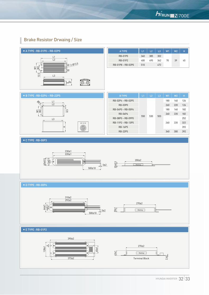
HYUNDAI INVERTER 32 33
L1L2
L3
H
13.5
W1
W2 2-Ø13.5
L2
L3
W1
Ø8.5
W2
8.5
H
L1
230±1
500±105±2
30±1
5±2500±10
390±2
373±2
128±
1
65±1
43±1
270±2
2.4tTerminal Block
Marking
6
310±2292±2
20±0
.5
200±2
270±2
60±0
.564
±16±
0.2
4.5±
0.5
220±1
Marking
Marking
A TYPE : RB-01P0 ~ RB-02P0
Brake Resistor Drwaing / Size
L1L2
L3
H
13.5
W1
W2 2-Ø13.5
L2
L3
W1
Ø8.5
W2
8.5
H
L1
230±1
500±105±2
30±1
5±2500±10
390±2
373±2
128±
1
65±1
43±1
270±2
2.4tTerminal Block
Marking
6
310±2292±2
20±0
.5
200±2
270±2
60±0
.564
±16±
0.2
4.5±
0.5
220±1
Marking
Marking
B TYPE : RB-02P4 ~ RB-22P5
L1L2
L3H
13.5
W1
W2 2-Ø13.5
L2
L3
W1
Ø8.5
W2
8.5
H
L1
230±1
500±105±2
30±1
5±2500±10
390±2
373±2
128±
1
65±1
43±1
270±2
2.4tTerminal Block
Marking
6
310±2292±2
20±0
.5
200±2
270±2
60±0
.564
±16±
0.2
4.5±
0.5
220±1
Marking
Marking
C TYPE : RB-00P3
L1L2
L3
H
13.5
W1
W2 2-Ø13.5
L2
L3
W1
Ø8.5
W2
8.5
H
L1
230±1
500±105±2
30±1
5±2500±10
390±2
373±2
128±
1
65±1
43±1
270±2
2.4tTerminal Block
Marking
6
310±2292±2
20±0
.5
200±2
270±2
60±0
.564
±16±
0.2
4.5±
0.5
220±1
Marking
Marking
D TYPE : RB-00P6
L1L2
L3
H
13.5
W1
W2 2-Ø13.5
L2
L3
W1
Ø8.5
W2
8.5
H
L1
230±1
500±105±2
30±1
5±2500±10
390±2
373±2
128±
1
65±1
43±1
270±2
2.4tTerminal Block
Marking
6
310±2292±2
20±0
.5
200±2
270±2
60±0
.564
±16±
0.2
4.5±
0.5
220±1
Marking
Marking
E TYPE : RB-01P2
L1
340
400
510
L2
385
495
L3
302
362
472
H
45
A TYPE
RB-01P0
RB-01P2
RB-01P8 ~ RB-02P0
W1
70
W2
39
W1
180
260
180
260
260
340
W2
140
220
140
220
220
300
H
126
126
182
182
252
322
392
392
B TYPE
RB-02P4 ~ RB-02P5
RB-03P0
RB-04P0 ~ RB-05P6
RB-06P6
RB-08P0 ~ RB-09P0
RB-11P2 ~ RB-13P5
RB-16P5
RB-22P5
L1
550
L2
530
L3
503

ㅣFor Correct Operationㅣ
Application to Motors | Application to General-purpose Motors
Before use, be sure to read through the Instruction manual to insure proper use of the inverter.Note that the inverter requires electrical wiring; a trained specialist should carry out the wiring.The inverter in this catalogue is designed for general industrial applications. For special applications in fields such as aircraft, nuclear power, transport,
vehicles, clinics, and underwater equipment, please consult us in advance.For application in a facility where human life is involved or serious losses may occur, make sure to provide safety devices to avoid a serious accident.The inverter is intended for use with a three-phase AC motor. For use with a load other than this, please consult with us.
Operating Frequency
Torque Characteristics
Motor Loss and Temperature Increase
Noise
Vibration
Power TransmissionMechanism
Application to Motors | Application to Special Motors
The allowable rotation range of continuous drive varies depending on the lubrication method or motor manufacturer (Particularly in case of oil lubrication, pay attention to the low frequency range). Grease lubrication has no degradation of lubrication ability even when the number of rotation decreases (Allowable frequency range: 6~120Hz).
For use of a brake-equipped motor, power supply for braking operation should be separately prepared. Connect the braking power supply to the primary side power of the inverter. Use brake operation (inverter stop) and free run stop (FRS) terminal to turn off inverter power.
There are different kinds of pole-change motors (constant output characteristic type, constant torque characteristic type, etc.), with different rated current values. In motor selection, check the maximum allowable current for each motor of a different pole count. At the time of pole change, be sure to stop the motor.
The rated current of a submersible motor is significantly larger than that of the general-purpose motor. In inverter selection, be sure to check the rated current of the motor.
Inverter drive is not suitable for a safety-enhanced explosion-proof type motor. The inverter should be used in combination with a pressure-proof and explosion-proof type of motor. 。。 Explosion-proof verification is not available for N700E series.
In most cases, the synchronous (MS) motor and the high-speed (HFM) motor are designed and manufactured to meet the specifications suitable for a connected machine. As to proper inverter selection, consult the manufacturer.
A single-phase motor is not suitable for variable-speed operation by an inverter drive. Therefore, use a three-phase motor.
Notes on Use | Drive
Run or stop of the inverter must be done with the keys on the operator panel or through the control circuit terminal.Installing an electromagnetic contactor (Mg) should not be used as a switch of run/stop.
When the protective function is operating or the power supply stops, the motor enters the free run stop state.When emergency stop or protection of motor is required, use of a mechanical brake should be considered.
N700E series can be set up to 400Hz. However it is extremely dangerous for rotational speed of two-pole motor to reach up to approx 24,000rpm. Therefore, carefully make selection and settings after checking the mechanical strength of the motor and connected machines. Consult the motor manufacturer when it is necessary to drive a standard (general-purpose) motor above 60Hz.
Run/Stop
Emergency Motor Stop
High-frequency Run
Application to Motors | Application to the 400V-class Motor
A system applying a voltage-type PWM inverter with IGBT may have surge voltage at the motor terminals resulting from the cable constants including the cable length and the cable laying method. Depending on the surge current magnification, the motor coil insulation may be degraded. In particular, when a 400V class motor is used, a longer cable is used, and critical loss can occur. Take the following countermeasures : (1) install the LCR filter between the inverter and the motor,(2) install the AC reactor between the inverter and the motor, or (3) enhance the insulation of the motor coil.
The overspeed endurance of a general-purpose motor is 120% of the rated speed for 2minutes (JIS C4004). For operation at higher than 60Hz, it is required to examine the allowable torque of the motor, useful life of bearings, noise, vibration, etc. In this case, be sure to consult the motor manufacturer as the maximum allowable rpm differs depending on the motor capacity, etc.
The torque characteristics of driving a general-purpose motor with an inverter differ from those of driving it using commercial power (starting torque decreases in particular). Carefully check the load torque characteristic of a connected machine and the driving torque characteristic of the motor.
An inverter-driven general-purpose motor heats up quickly at lower speeds. Consequently, the continuous torque level (output) will decrease at lower motor speeds. Carefully check the torque characteristics and speed range requirements.
When run by an inverter, a general-purpose motor generates noise slightly greater than by commercial power.
When run by an inverter at variable speeds, the motor may generate vibrations, especially because of (a) unbalance of the rotor including a connected machine, or (b) resonance caused by the natural vibration frequency of a mechanical system. Particularly, be careful of (c) when a machine previously fitted with a constant speed is operated at variable speed. Vibration can be minimized by (1) avoiding resonance points by using the frequency jump function of the inverter, (2) using a tire-shaped coupling, or (3) placing a rubber shock absorber under the motor base.
Under continued, low-speed operation, oil lubrication can deteriorate in a power transmission mechanism with an oil type gear box (gear motor) or transmission. Check with the motor manufacturer for the permissible range of continuous speed. To operate at more than 60Hz, confirm the machine’s ability to withstand the centrifugal force generated.
Gear Motor
Brake-equipped Motor
Pole-change Motor
Submersible Motor
Explosion-proof Motor
Synchronous (MS) Motor /High-speed (HFM) Motor
Single-phase Motor

Notes on Use | Main Power Supply
Installation ofan AC reactoron the Input Side
Using an Independent Electric Power Plant
Notes on Use | Installation Location and Operating Environment
Avoid installation in areas of high temperature, excessive humidity, or easy condensation of dew, as well as areas that are dusty, subject to corrosive gases, residue of grinding solution, or salt. Install the inverter away from direct sunlight in a well-ventilated room that is free of vibration.The inverter can be operated in the ambient temperature range from -10°C to 50°C
High-frequency Noise and Leakage Current
(1) High-frequency components are included in the input/output of the inverter main circuit, and they may cause interference in a transmitter, radio, or sensor if used near the inverter. The interference can be minimized by attaching noise filters (option) in the inverter.
(2) The switching of an inverter causes an increase of leakage current. Be sure to ground the inverter and the motor.
Lifetime of Primary Parts
Because a DC bus capacitor deteriorates as it undergoes internal chemical reaction, it should normally be replaced every five years. Be aware, however, that its life expectancy is considerably shorter when the inverter is subject to such adverse factors as high temperatures or heavy loads exceeding the rated current of the inverter. The figure at the right shows the approximate lifetime of the capacitor when it is used 24hours. Also, such moving parts as a cooling fan should be replaced. Maintenance, inspection and replacing parts must be performed by only specified professional engineers.
Am
bien
t Tem
pera
ture
( )
Capacitor Lifetime(years)
In the following examples involving a general-purpose inverter, a large peak current flows on the main power supply side, and could destroy the converter module. When such situations are predictable or connected crucial device is required to meet high reliability, install an AC reactor between the power supply and the inverter. Also, when influence of indirect lightning strike is possible, install a lightning arrester.
A) The unbalance factor of the power supply is 3% or higher1.1)
B) The power supply capacity is at least 10 times greater than the inverter capacity (the power supply capacity is 500kVA or more).C) Abrupt power supply changes are expected. Examples) ① Several inverters are interconnected with a short bus. ② A thyristor converter and an inverter are interconnected with a short bus. ③ Junction and disjunction of installed phase advance capacitor.
In cases (A), (B) and (C), it is recommended to install an AC reactor on the main power supply side.1) Example of how to calculate voltage unbalanced ratio. (voltage between lines on RS: VRS=205V, voltage between lines on ST : VST=201V, voltage between lines on TR: VTR=200V), max voltage between lines-average between lines= VRS-(VRS+VST+VTR)/3=205-202
·Voltage unbalanced ratio = Max. voltage between lines - Average voltage between lines
×100 = VRS-(VRS+VST+VTR)/3 ×100 =
205-202 ×
Average
voltage between lines
(VRS+VST+VTR)/3
202
100 = 1.5(%)
If an inverter is run by an independent electric power plant, harmonic current can cause to overheat the generator or distort output voltage waves of the generator. Generally, the generator capacity should be five times that of the inverter (kVA) in a PWM control system, or six times greater in a PAM control system.
Notes on Peripheral Equipment Selection
Wiring Connections
ElectromagneticContactor
Installing a Circuit Breaker
Wiring Distance
Earth Leakage Relay
Phase Advance Capacitor
Thermal Relay
WiringbetweenInverterandMotor
(1) Be sure to connect main power wires with R (L1), S (L2), and T (L3) (input) terminals and motor wires to U (T1), V (T2), and W (T3) terminals (output). (Incorrect connection will cause an immediate failure.)
(2) Be sure to provide a grounding connection with the ground terminal( )
When an electromagnetic contactor is installed between the inverter and the motor, do not perform on-off switching during running.
When used with standard output motors (standard three-phase squirrel cage four pole motors), the N700E series does not need a thermal relay for motor protection due to the internal electronic protective circuit. A thermal relay, however, should be used: during continuous running out of a range of 30Hz to 60Hz for motors exceeding the range of electronic thermal adjustment (rated current). When several motors are driven by the same inverter, install a thermal relay for each motor. The RC value of the thermal relay should be more than 1.1times the rated current of the motor. Where the wiring length is 10m or more, the thermal relay tends to turn off readily. In this case, provide an AC reactor on the output side or use a current sensor.
Install a circuit breaker on the main power input side to protect inverter wiring and ensure personal safety. Choose a circuit breaker compatible with inverter.
The wiring distance between the inverter and the remote operator panel should be 20meters or less. When this distance is exceeded, use CVD-E (current-voltage converter) or RCD-E (remote control device). Shielded cable should be used on the wiring.Beware of voltage drops on main circuit wires (A large voltage drop reduces torque).
If the earth leakage relay (or earth leakage breaker) is used, it should have a sensitivity level of 15mA or more (per inverter).Leakage current is depending on the length of the cable.
Do not use a capacitor for improvement of power factor between the inverter and the motor because the high-frequency components of the inverter output may overheat or damage the capacitor
HYUNDAI INVERTER 34 35

HH
IS-WC
-CE-B
27-03, 2011.9 Designed by JC
Com
munication
Head Office 1 Jeonha-dong, Dong-gu, Ulsan, Korea Tel: 82-52-202-8101~8 Fax: 82-52-202-8100
Seoul 140-2, Gye-dong, Jongno-gu, Seoul, Korea (Sales & Marketing) Tel: 82-2-746-7596 Fax: 82-2-746-7679
Orlando 4700 Millenia Blvd., Suite 370, Orlando, Florida 32839, U.S.A. Tel: 1-407-249-7350 Fax: 1-407-275-4940
New Jersey 300 Sylvan Avenue, Englewood Cliffs, NJ, 07632, U.S.A. Tel: 1-201-816-0286, 8028 Fax: 1-201-816-4083
Chicago 1090 Fargo Avenue Elk Grove Village, IL60007, U.S.A. Tel: 1-847-228-8845 Fax: 1-847-437-3574
London 2nd Floor, The Triangle, 5-17 Hammersmith Grove, London, W6 0LG, UK Tel: 44-20-8741-0501 Fax: 44-20-8741-5620
Tokyo 8th Fl., Yurakucho Denki Bldg.1-7-1, Yuraku-cho, Chiyoda-gu, Tokyo, 100-0006, Japan Tel: 81-3-3212-2076, 3215-7159 Fax: 81-3-3211-2093
Osaka I-Room 5th Fl. Nagahori-Plaza Bldg. 2-4-8, Minami Senba, Chuo-Ku, Osaka, 542-0081, Japan Tel: 81-6-6261-5766, 5767 Fax: 81-6-6261-5818
Riyadh 2nd Floor, the Plaza, P.O.Box 21840 Riyadh 11485, Saudi Arabia Tel: 966-1-462-2331 Fax: 966-1-464-4696
Dubai 205, Building 4, Emaar Square, Sheikh Zayed Road, Pobox 252458, Dubai, UAE Tel: 971-4-425-7995 Fax: 971-4-425-7996
Kuwait Floor 15, Al Sour Tower, Al Sour Street, Al-Qiblah, Kuwait Tel: 965-2291-5354 Fax: 965-2291-5355
Moscow World Trade Center, Ent. 3, #1902, Krasnopresnenskaya Nab.12, Moscow, 123610, Russia Tel: 7-495-258-1381 Fax: 7-495-258-1382
Madrid Paseo De La Castellana 216, Planta 0, 28046 Madrid, Spain Tel: 34-91-732-0454 Fax: 34-91-733-2389
Sofia 1271, Sofia 41, Rojen Blvd., Bulgaria Tel: 359-2-803-3200, 3220 Fax: 359-2-803-3203
Montgomery 201 Folmar Parkway, Montgomery, AL 36105, U.S.A. Tel: 1-334-230-9921 Fax: 1-334-240-6869
Yangzhong No.9 Xiandai Road, Xinba Scientific and Technologic Zone, Yangzhong, Jiangsu, P.R.C. Zip: 212212, China Tel: 86-511-8842-0666, 0212 Fax: 86-511-8842-0668, 0231
www.hyundai-elec.com