hypersonic weapons technology shear testing of hypersonic
TRANSCRIPT

DISTRIBUTION STATEMENT A: Approved for public release; distribution unlimited
Document 0609A-2002-016
Tri-service Sponsored Symposium on Advancements in Heatshield Technology
April 16-18, 2002
Hypersonic Weapons Technology Shear Testing of Hypersonic Heatshield Materials at
the NASA Hot Gas Test Facility
by
Michael Rembert Aerotherm Corporation
1500 Perimeter Parkway Suite 225 Huntsville, Alabama 35806
(256) 830-1230, x23 [email protected]
Forrest Strobel
Aerotherm Corporation 1500 Perimeter Parkway Suite 225
Huntsville, Alabama 35806 (256) 830-1230, x26
Gerald Russell AMCOM
Propulsion and Structures Directorate Redstone Arsenal, Alabama
(256) 876-1712 [email protected]
Warren Jaul
Naval Air Warfare Center Code 473110D
China Lake, California 93555 (760) 939-8890
ITT Industries Enpneered tor life

Report Documentation Page Form ApprovedOMB No. 0704-0188
Public reporting burden for the collection of information is estimated to average 1 hour per response, including the time for reviewing instructions, searching existing data sources, gathering andmaintaining the data needed, and completing and reviewing the collection of information. Send comments regarding this burden estimate or any other aspect of this collection of information,including suggestions for reducing this burden, to Washington Headquarters Services, Directorate for Information Operations and Reports, 1215 Jefferson Davis Highway, Suite 1204, ArlingtonVA 22202-4302. Respondents should be aware that notwithstanding any other provision of law, no person shall be subject to a penalty for failing to comply with a collection of information if itdoes not display a currently valid OMB control number.
1. REPORT DATE 00 APR 2002
2. REPORT TYPE N/A
3. DATES COVERED -
4. TITLE AND SUBTITLE Hypersonic Weapons Technology Shear Testing of Hypersonic HeatshieldMaterials at the NASA Hot Gas Test Facility
5a. CONTRACT NUMBER
5b. GRANT NUMBER
5c. PROGRAM ELEMENT NUMBER
6. AUTHOR(S) 5d. PROJECT NUMBER
5e. TASK NUMBER
5f. WORK UNIT NUMBER
7. PERFORMING ORGANIZATION NAME(S) AND ADDRESS(ES) Aerotherm Corporation 1500 Perimeter Parkway Suite 225 Huntsville,Alabama 35806; AMCOM Propulsion and Structures DirectorateRedstone Arsenal, Alabama; Naval Air Warfare Center Code 473110DChina Lake, California 93555
8. PERFORMING ORGANIZATIONREPORT NUMBER
9. SPONSORING/MONITORING AGENCY NAME(S) AND ADDRESS(ES) 10. SPONSOR/MONITOR’S ACRONYM(S)
11. SPONSOR/MONITOR’S REPORT NUMBER(S)
12. DISTRIBUTION/AVAILABILITY STATEMENT Approved for public release, distribution unlimited
13. SUPPLEMENTARY NOTES See also ADM201519., The original document contains color images.
14. ABSTRACT
15. SUBJECT TERMS
16. SECURITY CLASSIFICATION OF: 17. LIMITATION OF ABSTRACT
UU
18. NUMBEROF PAGES
12
19a. NAME OFRESPONSIBLE PERSON
a. REPORT unclassified
b. ABSTRACT unclassified
c. THIS PAGE unclassified
Standard Form 298 (Rev. 8-98) Prescribed by ANSI Std Z39-18

DISTRIBUTION STATEMENT A: Approved for public release; distribution unlimited
1.0 Introduction
During the past three years, a team consisting of the Naval Air Warfare Center (NAWC), the U.S. Army Aviation and Missile Command (AMCOM) and ITT Aerotherm has been developing thermal protection systems for advanced high-speed missile applications. To date, the development has consisted of evaluating 32 different thermal protection systems (TPS) in representative flight environments. The 32 materials were comprised of proven and unproven aerospace TPS materials ranging from low density ablators to higher density intumescents. Aerothermal tests were performed at the NASA Marshall Hot Gas Facility (HGF). For these tests, materials were subjected to aerothermal heating conditions representative of high altitude and high velocity flight conditions. Two separate test series were conducted with the latter consisting of the best performing 16 of the 33 materials. Since all materials were tested at the same nominal thickness, the top performing material selection was based on a derived performance parameter that equally accounted for weight and volume thereby allowing for a direct comparison between the higher and lower density materials.
Based on the performance parameter, results from both test series showed that Intumescent 1 was clearly the best performing TPS material. This material not only received the highest performance rating when material density was considered, but it also maintained the backwall structure at the lowest temperature during the test. This material apparently out performs the other materials because of its intumescent behavior and relatively strong char that is developed. The intumescent behavior is characterized by swelling that occurs as the material is heated and decomposes. A low density char is produced that has a low thermal conductivity. The swelling behavior is a significant phenomena (material expands 2-4 times its original thickness in the heat effected regions) and produces a much greater conduction path that further reduces the transfer of heat into the material. However, there is one undesirable characteristic that is associated with the intumescent behavior, a rough external surface.
For the intended application the rough surface could potentially increase the skin friction drag by undesirable amounts. To better quantify this potential problem a third test series has been conducted to measure the skin friction of the top performing material candidates. As part of this effort, a surface shear test fixture has been developed for use at the HGF. The developed surface shear fixture provides the capability to measure surface shear for large test panels using a decomposing or non-decomposing material. This paper documents the development and results for the surface shear test series.
2.0 Test Materials
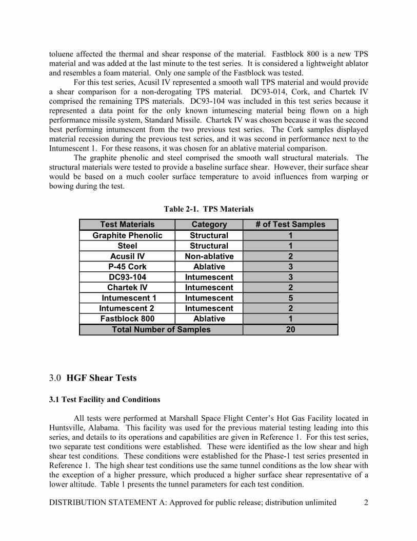
In addition to the Intumescent 1 TPS material, six other TPS materials and two structural materials were tested. Table 2-1 presents these materials and their category. The additional TPS materials were Intumescent 2, DC93-104, Cork, Chartek IV, Acusil IV, and Fastblock 800. Each additional TPS material was chosen based on its surface behavior displayed from the previous test series with the exception of Intumescent 2 and Fastblock 800. These materials were not part of the previously tested 32 materials. Intumescent 2 has the same chemical composition as Intumescent 1 with the exception of not being thinned with toluene during the materials application. Intumescent 2 was included for this test series to determine if the introduction of
DISTRIBUTION STATEMENT A: Approved for public release; distribution unlimited
2
toluene affected the thermal and shear response of the material. Fastblock 800 is a new TPS material and was added at the last minute to the test series. It is considered a lightweight ablator and resembles a foam material. Only one sample of the Fastblock was tested.
For this test series, Acusil IV represented a smooth wall TPS material and would provide a shear comparison for a non-derogating TPS material. DC93-014, Cork, and Chartek IV comprised the remaining TPS materials. DC93-104 was included in this test series because it represented a data point for the only known intumescing material being flown on a high performance missile system, Standard Missile. Chartek IV was chosen because it was the second best performing intumescent from the two previous test series. The Cork samples displayed material recession during the previous test series, and it was second in performance next to the Intumescent 1. For these reasons, it was chosen for an ablative material comparison.
The graphite phenolic and steel comprised the smooth wall structural materials. The structural materials were tested to provide a baseline surface shear. However, their surface shear would be based on a much cooler surface temperature to avoid influences from warping or bowing during the test.
Table 2-1. TPS Materials
3.0 HGF Shear Tests 3.1 Test Facility and Conditions
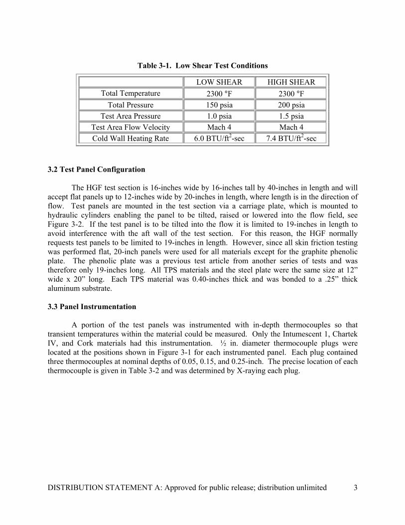
All tests were performed at Marshall Space Flight Center’s Hot Gas Facility located in Huntsville, Alabama. This facility was used for the previous material testing leading into this series, and details to its operations and capabilities are given in Reference 1. For this test series, two separate test conditions were established. These were identified as the low shear and high shear test conditions. These conditions were established for the Phase-1 test series presented in Reference 1. The high shear test conditions use the same tunnel conditions as the low shear with the exception of a higher pressure, which produced a higher surface shear representative of a lower altitude. Table 1 presents the tunnel parameters for each test condition.
Test Materials Category # of Test Samples Graphite Phenolic Structural 1
Steel Structural 1 Acusil IV Non-ablative 2 P-45 Cork Ablative 3 DC93-104 Intumescent 3 Chartek IV Intumescent 2
Intumescent 1 Intumescent 5 Intumescent 2 Intumescent 2 Fastblock 800 Ablative 1
20 Total Number of Samples
DISTRIBUTION STATEMENT A: Approved for public release; distribution unlimited
3
Table 3-1. Low Shear Test Conditions
LOW SHEAR HIGH SHEAR Total Temperature 2300 °F 2300 °F
Total Pressure 150 psia 200 psia Test Area Pressure 1.0 psia 1.5 psia
Test Area Flow Velocity Mach 4 Mach 4 Cold Wall Heating Rate 6.0 BTU/ft2-sec 7.4 BTU/ft2-sec
3.2 Test Panel Configuration
The HGF test section is 16-inches wide by 16-inches tall by 40-inches in length and will accept flat panels up to 12-inches wide by 20-inches in length, where length is in the direction of flow. Test panels are mounted in the test section via a carriage plate, which is mounted to hydraulic cylinders enabling the panel to be tilted, raised or lowered into the flow field, see Figure 3-2. If the test panel is to be tilted into the flow it is limited to 19-inches in length to avoid interference with the aft wall of the test section. For this reason, the HGF normally requests test panels to be limited to 19-inches in length. However, since all skin friction testing was performed flat, 20-inch panels were used for all materials except for the graphite phenolic plate. The phenolic plate was a previous test article from another series of tests and was therefore only 19-inches long. All TPS materials and the steel plate were the same size at 12” wide x 20” long. Each TPS material was 0.40-inches thick and was bonded to a .25” thick aluminum substrate. 3.3 Panel Instrumentation
A portion of the test panels was instrumented with in-depth thermocouples so that
transient temperatures within the material could be measured. Only the Intumescent 1, Chartek IV, and Cork materials had this instrumentation. ½ in. diameter thermocouple plugs were located at the positions shown in Figure 3-1 for each instrumented panel. Each plug contained three thermocouples at nominal depths of 0.05, 0.15, and 0.25-inch. The precise location of each thermocouple is given in Table 3-2 and was determined by X-raying each plug.

DISTRIBUTION STATEMENT A: Approved for public release; distribution unlimited
4
Figure 3-1. Instrumented TPS Panel
Table 3-2. Thermocouple Locations for Instrumented Panels
3.4 HGF Surface Shear Fixture
A detailed report to the design of the HGF Surface Shear Fixture is given in Reference 2. The skin friction fixture, shown in Figure 3-2 mounted within the HGF test section, consists of two low friction, linear guide rails, a 25-pound loadcell, a gap adjustment plate, an adapter plate, a base plate and a locking linear actuator. The linear guides are mounted on top of the base plate, which, in turn, is mounted to the carriage plate of the HGF’s test section; the fixture mounts to the carriage plate as an assembly. The adapter plate is mounted to the pillar blocks of
TC Plug 1
TC Plug 2
FLOW
Thermcouple Plugs Nominal
DepthFastblock
800TC Plug 1 Panel 1 Panel 2 Pnael 3 Panel 4 Panel 1 Panel 3 Panel 1 Panel 2 Panel 3 Panel 1
TC1 (0.050) 0.05 0.046 0.05 0.05 0.05 0.052 0.05 0.05 0.05 0.035TC2 (0.150) 0.15 0.152 0.15 0.145 0.145 0.15 0.15 0.15 0.15 0.143TC3 (.0250) 0.25 0.248 0.25 0.248 0.25 0.253 0.25 0.25 0.25 0.242TC Plug 2 Panel 1 Panel 2 Pnael 3 Panel 4 Panel 1 Panel 3 Panel 1 Panel 2 Panel 3 Panel 1
TC1 (0.050) 0.056 0.052 0.05 0.053 0.055 0.052 0.05 0.05 0.05 0.045TC2 (0.150) 0.155 0.152 0.15 0.15 0.156 0.15 0.145 0.15 0.15 0.14TC3 (.0250) 0.252 0.255 0.25 0.25 0.256 0.25 0.25 0.25 0.25 0.243
Intumescent 1 Chartek IV Cork

DISTRIBUTION STATEMENT A: Approved for public release; distribution unlimited
5
the linear guides and is free to move forward and back on the guide rails. The movement of the adapter plate is limited at the forward end of the fixture by a gap adjustment screw and the rearward movement, in the direction of flow, is limited by the loadcell. The gap adjustment screw is adjusted to control the amount of movement of the adapter plate; for a test maximum movement is usually set to 0.008-inch. The test panel attaches directly to the adapter plate and can be removed or installed once the fixture is positioned in the tunnel. The test panel and spacer plate will slide together as a unit on the linear guides. Prior to test start-up and shutdown, the locking linear actuator is engaged thereby restraining the test panel from moving; this protects the loadcell from the high loading caused from the facility startup and shutdown shockwaves. After tunnel flow has stabilized, the linear actuator is disengaged. The force of the tunnel flow pushes the test panel forward against the loadcell, which measures the force for determining wall shear.
Figure 3-2. HGF Shear Fixture 3.5 Test Results
Each TPS material was tested in two stages. The first, identified as the thermal test, consisted of testing the material at the prescribed conditions for an extended period of time in order to fully develop the char layer; test times for the low and high shear conditions were 200 and 150 seconds, respectively. At the completion of this test, the material was inspected from within the tunnel and its leading edge repositioned flush with the tunnel wall; the test panel was
Fwd Actuator Rear Actuator
Tunnel Wall
Linear Guide
0.008” Gap 25 lbLoadcell
Flow
Gap Adjustment Screw
Test Panel
ISO-ViewTest Panel not shown
Locking Linear ActuatorGap Adjustment Plate
Test Panel Height
Adjustment
Leading Edge of Plate
Fwd Actuator Rear Actuator
Tunnel Wall
Linear Guide
0.008” Gap 25 lbLoadcell
Flow
Gap Adjustment Screw
Test Panel
ISO-ViewTest Panel not shown
Locking Linear ActuatorGap Adjustment Plate
Test Panel Height
Adjustment
Leading Edge of Plate

DISTRIBUTION STATEMENT A: Approved for public release; distribution unlimited
6
lowered by the amount it swelled. The second step, identified as the shear test, consisted of testing the material at the same conditions but for a much shorter time, approximately 30 to 50 seconds. After the test, the material was re-inspected to ensure additional charring did not incur which would have caused leading edge development. The surface shear value for each material was based on the test results from the second step. By ensuring a leading edge did not develop during the shear test, the measured force represented the material’s surface roughness. A total of 31 tests were completed. All panels tested were 12” by 20” with the exception of the graphite phenolic which was 12” by 19”, hence the panel area difference. A total of five Intumescent 1 and two Intumescent 2 panels were tested. Of these, panels 1 through 4 of the Intumescent 1 were instrumented; the others were not.
Tables 3-3 and 3-4 present the results from the low and high shear tests, respectively. As expected, the Intumescent 1 had the lowest thermal response for both test series with 135 °F for the low shear and 80 °F for the high shear. Of the TPS materials, the Chartek IV resulted in the highest shear for the low shear test series, and panel 1 of the Intumescent 1 resulted in the lowest shear with 2.31 lb/ft2. Panel 1 of the Intumescent 1 developed an unexpected smooth char surface, which attributed to the lowest TPS shear level for the test series. The smooth char development did not affect the material’s thermal capabilities. Figures 3-3 and 3-4 compare surface smoothness of panel 1 and 2 of the Intumescent 1. For the high shear test series, panel 3 of the Intumescent 1 resulted in the highest shear with 6.60 lb/ft2, and panel 5 of Intumescent 1 resulted in the lowest with 1.72 lb/ft2. Again, one of the Intumescent 1 panels, panel 5, developed a smooth char layer resulting in the lowest shear response. Reasons for the difference in surface char development are not apparent at this time.

DISTRIBUTION STATEMENT A: Approved for public release; distribution unlimited
7
Table 3-3. Low Shear Condition Test Results
Table 3-4. High Shear Condition Test Results
0.25" Thermocouple Response @ 200 seconds
AVG Load Cell Reponse
AVG Shear
Panel Area
ft2 Thermal Shear
Graphite Phenolic 1 1.58 641 x 2.85 1.80
Steel 1 1.67 257 x 2.98 1.78
Acusil IV 1 1.67 276 x 3.21 1.92
642 x 135643 x 3.85 2.31656 x 150657 x 6.40 3.83645 x 150646 x 8.32 4.98654 x 210655 x 4.38 2.62660 x 210
661 x 5.13 3.071 1.67 650 x 4.38 2.622 1.67 659 x 4.91 2.94
664 x 400
1.67
1.67
1.67
1.67
Chartek IV
psfHGF Run No.
2
2 1.67
Test TypeF lbf
1
DC93-104
Panel
1
1Cork
Intumescent 1
Material
*Lost portion of material during thermal test, resulting pocket prevented obtaining accurate surface shear measurements of material therefore surface shear test was omitted.
Fastblock 800 1 1.67N/A*
0.25" Thermocouple Response @ 150 seconds
AVG Load Cell Reponse
AVG Shear
Panel Area
ft2 Thermal Shear
Graphite Phenolic 1 1.58 666 x 4.67 2.96
Steel 1 1.67 816 x 4.04 2.42
Acusil IV 2 1.67 331 x 4.07 2.44
892 x 80893 x 11.03 6.98900 x 120901 x 8.54 5.41
5 1.67 903 x 2.87 1.72
894 x 150895 x 8.32 4.98898 x 210899 x 4.38 2.62
DC93-104 3 1.67 897 x 4.38 2.62
1 1.58 907 x 4.56 2.892 1.58 912 x 5.85 3.70
Intumescent 2
psfHGF Run No.
Intumescent 1 1.58
Test TypeF lbf
3
PanelMaterial
1.58
1.67
1.67
4
Cork
Chartek IV 3
3

DISTRIBUTION STATEMENT A: Approved for public release; distribution unlimited
8
Figure 3-3. Post Test Photo of Intumescent 1 Panel 1
Figure 3-4. Post Test Photo of Intumescent 1 Panel 2

DISTRIBUTION STATEMENT A: Approved for public release; distribution unlimited
9
4.0 Summary and Conclusions A shear test series has been completed for quantifying the relative surface shear effects of Intumescent 1. The results show, for normal char development of the Intumescent 1, an increase over a non-ablating material of 112% at the low shear test conditions and a 122% increase at the high shear test conditions. However, it was also shown, the Intumescent 1 is capable of developing a smooth char surface without sacrificing its thermal capabilities. For the smooth char development the corresponding increases over the non-ablating material at the low shear conditions were only 28%, which was the lowest increase for all tested TPS materials, and a 42% decrease in shear was shown for the high shear conditions; the decrease has been attributed to hot wall effects. As of yet, reasons for the differences in surface char development are not explainable.
Initial investigations with the material’s vendor tend to attribute the char differences to the application process of the material, since all panels were sprayed at the same time using the same pour. Intumescent 1 is a two-component mixture with the mixture occurring during the spray process. The control over the mixture ratio is said to be good and was consistent for all tested panels. However, during the spraying process, toluene is introduced as a thinning agent. Control of the toluene does not seem to be as high and may be an attributor to the surface variations. Cross-section inspection of pretest material samples has revealed a porosity difference between the smooth and rough surface materials. The rough surface material has greater porosity, at least in the samples compared. Evaporation of the toluene, if heavily applied during the spray process, may attribute to the material’s porosity. Two Intumescent 2 samples were also tested for the high shear test conditions. The results from these panels were lower than that of the rough surface sprayed Intumescent 1, but their corresponding surface was rough in comparison to the smooth char Intumescent 1 panels. So, toluene may also aid in the smooth char development.
These results clearly need to be further investigated through material deformualtion and additional testing aimed at uncovering the surface char variations. Refining the Intumescent 1 material to ensure smooth char development could result in a material far superior than any other TPS material in use today.

DISTRIBUTION STATEMENT A: Approved for public release; distribution unlimited
10
5.0 References 1. Rembert, M., Strobel, F., and King, B., “Thermal Protection System Development for the
Hypersonic Weapons Technology Program,” Report No. 0609A-2001-002, ITT Aerotherm, February 2001.
2. “Development of a Surface Shear Test Fixture for Intumescing and Ablating Materials,” Report No. 0609A-2001-015, ITT Aerotherm, October