hyperseeing spring 2011 - isama · for the past 21 years, the ski town of breckenridge, colorado,...
TRANSCRIPT

HYPERSEEINGEditors. Ergun Akleman, Nat Friedman.
Associate Editors. Javier Barrallo, Anna Campbell Bliss, Claude Bruter, Benigna Chilla, Michael Field, Slavik Jablan, Steve Luecking, John Sullivan, Elizabeth Whiteley.
Page Layout. Ergun Akleman
SPRING 2011
Cover Image: Eva Hild’s Perpetual Motion (Snow Sculpture)
Article Submission
For inclusion in Hyperseeing, au-thors are invited to email articles for the preceding categories to: [email protected]
Articles should be a maximum of eight pages.
Articles
Eva Hild’s Perpetual Motion by Eva Hild, Dan Schwalbe, Richard Seeley, Beth Hass-inger Seeley and Stan Wagon
Nicola Carrino by Nat Friedman
Hypersculptures: Four Right Angles by Nat Friedman
Malbec by Gabriel Esquivel
Robert Longhurst: Recent Sculptures by Nat Friedman
Conics in Antonio Gaudi’s Palau Guell by Stephen Lueckin
Sculpture Generator by Mehrdad Garousi
From Chemistry to Art by Susan Van der eb Greene
A Graphics Researcher from 15th Century by Ergun Akleman
Reviews
JMM 2011 Prize Winners by Nat Friedman
Cartoons
Illustration by Robert Kauffmann
MADmatic by Ergun Akleman
Caricature of Benoit Mandelbrot by Ergun Akleman
Announcements
ISAMA 2010- Chicago June 13-17
ISAMAwww.isama.org
The International Society of the Arts, Mathematics, and Architecture
BECOME A MEMBER
ISAMA 2011
Columbia College, Chicago, ILJune 13-17, 2011
First Announcement
ISAMA 2011 is scheduled for June 13-17, 2011 and will be hosted by Columbia College in downtown Chicago, IL. The conference will be co-organized with Pangratios Papacosta of Columbia College. There will be talks Monday thru Wednesday, excursions on Thursday, and workshops on Friday. The cost of the excursions, one copy of the Proceedings, and lunches on Thursday and Friday will be included in the registration fee of $200. There will also be an exhibit of works by conference participants.
More details, including information on invited speakers, registration, and submitting papers, will follow.
ISAMA Membership Registration
Membership in ISAMA is free. Membership implies you will receive all ISAMA email announcements concerning conferences and other news items of interest.
Name………………………………………………………………………………………………………………….
Address……………………………………………………………………………………………………………………………………………………………………………………………………………………………………………………………………………………………………………………………………………………………………………………………………………………………………………………………………………………………………………………………………………………………………………………………………………………………………………………………………………………………………………………………………………………………
Email address…………………………………………………………………………………………………………………………….
Interests…………………………………………………………………………………………………………………………………………………………………………………………………………………………………………………………………………………………………………………………………………………………………………………………………………………………………………………………………………………………………………………………………………………………………………………………………………………………………………………………………………………………………………………………………………………………………………………………………………………………………………………………………………………………………………………
Please email completed form to Nat Friedman at [email protected]
BECOME A MEMBER
EVA HILD S PERPETUAL MOTION IN SNOW Ê
Eva Hild <[email protected]> Dan Schwalbe <[email protected]> Richard Seeley <[email protected]>
Beth Hassinger Seeley <[email protected]> Stan Wagon <[email protected]>
Ê
Introduction
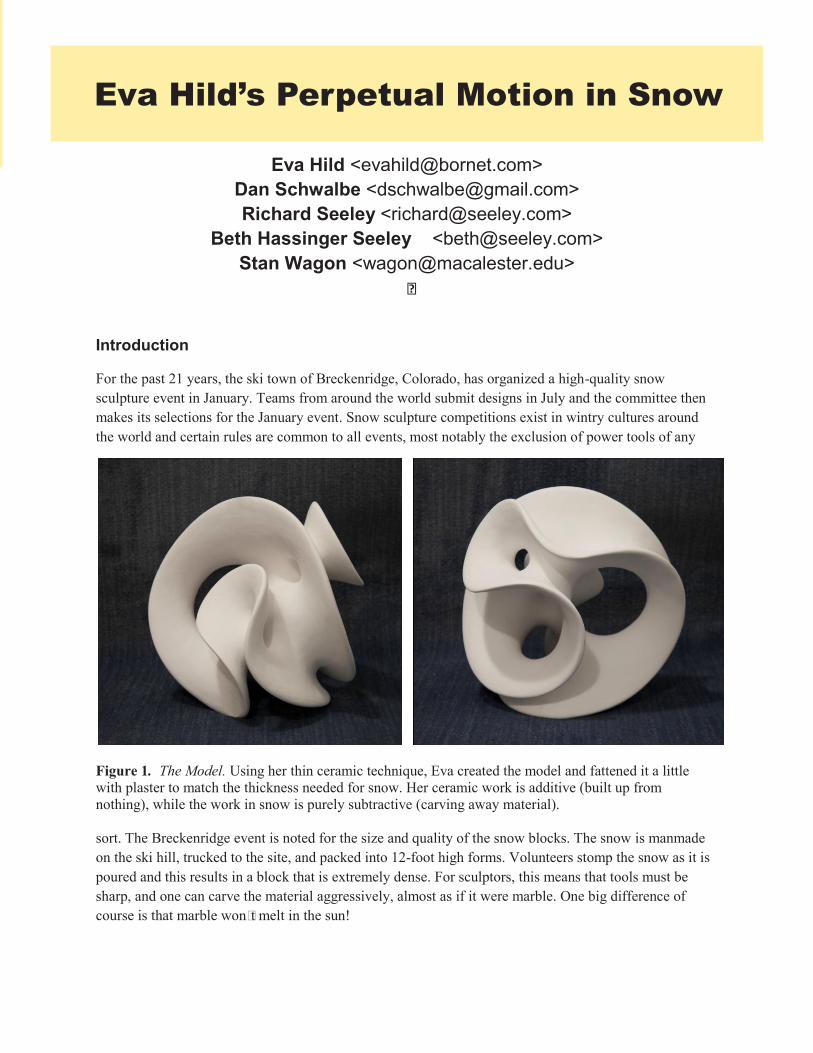
For the past 21 years, the ski town of Breckenridge, Colorado, has organized a high-quality snow sculpture event in January. Teams from around the world submit designs in July and the committee then makes its selections for the January event. Snow sculpture competitions exist in wintry cultures around the world and certain rules are common to all events, most notably the exclusion of power tools of any
sort. The Breckenridge event is noted for the size and quality of the snow blocks. The snow is manmade on the ski hill, trucked to the site, and packed into 12-foot high forms. Volunteers stomp the snow as it is poured and this results in a block that is extremely dense. For sculptors, this means that tools must be sharp, and one can carve the material aggressively, almost as if it were marble. One big difference of course is that marble won# t melt in the sun!
Figure 1. The Model. Using her thin ceramic technique, Eva created the model and fattened it a little with plaster to match the thickness needed for snow. Her ceramic work is additive (built up from nothing), while the work in snow is purely subtractive (carving away material).
ISAMA
BECOME A MEMBERISAMA Membership Registration
Membership in ISAMA is free. Membership implies you will receive all ISAMA email announcements concerning conferences and other news items of interest.
Name………………………………………………………………………………………………………………….
Address……………………………………………………………………………………………………………………………………………………………………………………………………………………………………………………………………………………………………………………………………………………………………………………………………………………………………………………………………………………………………………………………………………………………………………………………………………………………………………………………………………………………………………………………………………………………
Email address…………………………………………………………………………………………………………………………….
Interests…………………………………………………………………………………………………………………………………………………………………………………………………………………………………………………………………………………………………………………………………………………………………………………………………………………………………………………………………………………………………………………………………………………………………………………………………………………………………………………………………………………………………………………………………………………………………………………………………………………………………………………………………………………………………………………
Please email completed form to Nat Friedman at [email protected]
Eva Hild’s Perpetual Motion in Snow

In early 2010, Stan saw the Hyperseeing article [1] presenting the elegant negative curvature sculptures of Eva Hild. Their shape and whiteness were crying out to be interpreted in snow. For a comprehensive discussion of Eva's work, see the beautifully produced book [6].
Stan’s team had sculpted ten giant shapes at Breckenridge, most emphasizing negative curvature, and upon learning of their experience [2,4,5], Eva saw the potential in the medium and agreed to join them in January 2011, for their eleventh effort.
Our team, and several Swiss teams, has carried the flag for abstract sculptures, which are otherwise rare at this event; the work is mainly representational: animals, humans, and folk myths. What we wanted from Eva was an attractive abstract shape that fully used the three-dimensional block and highlighted her style of uniform thinness and strong negative curvature. Eva came up with a design that we christened Perpetual Motion. It had everything we wanted: enough complexity to be interesting and challenging, but also swooping curves and sheets that would look good at the large size. An elegant aspect was the fact that its boundary was a single curve. And it certainly used the whole block, as the bounding curve twisted its way into and away from the corners and sides.
The result of the months of planning and week of hard work was a striking sculpture carved by hand from 20 tons of snow. Only pictures remain; all the photos in this article are by Richard Seeley. Some videos (night and day) showing a 360-degree view of the finished piece may be seen at [3].
Practice
Eva survived 24 hours of travel from Sweden and an altitude change of almost two miles, and joined the team in immediately attacking the 40% scale (4 feet by 4 feet by 5 feet) practice block Stan constructed. They carved that over two days, continually refining the plan and learning where the difficult parts were. The plan was based on measurements Rich and Stan made from Eva's model, sent earlier, and a sequence of cutting planes formulated by Dan and Stan, with help from Mathematica's three-dimensional visualization.
Figure 2. The practice sculpture. Figure 3. The blocks await.
The practice sculpture (Figure 2) may not be pretty, but it taught us where the difficulties lie. In this case, we learned that great care would be needed at the stack of holes and troughs near the smaller of the two protruding horns. There would be no room for error when carving in that region.
Days 1 and 2, Tuesday and Wednesday
Figure 3 shows the blocks of extremely dense snow, which were carefully prepared by the town for the 15 teams from Mexico, Austria, Australia, Germany, the Netherlands, Yukon, Quebec, Alaska, Colorado, Wisconsin, Vermont, and our joint Sweden/USA team. Thanks to the practice sessions, our team arrived at the competition site at 11 am on Tuesday ready to work efficiently. Our first step is to place a marked wooden frame around the base, but that was not so easy as recent snows meant that the base was surrounded by several inches of plowed snow. That had to be hacked away, but then the frame slid into place and we could start.
We spent the first hours marking up the block, using the frame and a plumb line to translate measurements taken earlier from the model (see Figure 4). The single edge bounding the sculpture was convenient as we used 33 points in sequence along that edge. Our first cutting mission was to slice off some large prisms and tetrahedra. This year, for the first time, we had an effective wire saw made by attaching rivets to a long length of thin, strong wire and could cut giant planes fairly easily. We started with a high tetrahedron (Figure 5) and that came off easily and cleanly. Then we moved to a vertical prism that again came off well. Dropping a block of snow that weighs over five thousand pounds is always fun (Figure 6).
The initial carving goes very slowly. Figure 7 shows Eva using a curved shovel to start one of the many troughs between the edges.
Day 3, Thursday
At the beginning of the day there were no holes at all. But now we could no longer hold back, and quickly brought out two ice-fishing augers to start developing the topology. Drilling large holes is a little scary, so we tested most of them first by driving a thin steel rod in the same direction. By 9 pm we had all the holes
Figure 4. Marking up the block Figure 5. Our new wire saw on a high tetrahedron.

defined but one (see Figure 9). The next job would be tying the holes together to get the elegant saddles that link them.
Figure 6. The large prisms came off quickly and cleanly.
Day 4, Friday
Sculpting is allowed from 7 am Friday straight through to the end, 10 am on Saturday. We worked for almost that whole period, napping from 2 am to 5 am on Saturday. Most of the time was spent refining the curves and reducing the surfaces. Carving the circular base was straightforward by first slicing a circumscribed 16-gon and then using a specially designed tool to get the nine-foot diameter (see Figure 10). There was strong sun these two days, but our design has no detail to melt away and was not damaged by the sun. We did use a sail for shading on Friday (see Figure 17), as that minimizes the loss of material. One nice feature is that even if the strong sun makes sculpting impossible in the middle of the day, the night temperatures are always low enough to freeze things solid again, allowing work to continue.
The Finish on Saturday
Figures 11–16 show the finished piece. We rounded all the edges and got the faces as thin as we dared; the result was a very close reproduction of Eva’s model (Figure 11). The view from the south in Figure 12 shows the large mass of material on the southwest corner, placed there as it would not be harmed by the sun. This view also shows the horn on the right that is the crux of the sculptural difficulty, as there is a hole through the horn, and below it, a tunnel below that, a trough behind the horn, and a hole exiting the trough on the right. The view in Figure 13 emphasizes the similar curves and the play of light and shadow, so much a part of Eva's vision.
Figure 9. Sculpture by 9 pm on Thursday.
Figure 7. On Wednesday we started to carve. Figure 8. At the beginning of the third day, Thursday.

Figure 14 shows the north view that emphasizes the single continuous curve that bounds the entire surface. Figure 15 shows the new LED lighting system, which yielded some interesting effects. This northwest view was taken at 5 am on Monday. Figure 16 shows the team right at the conclusion of sculpting. Figure 17 shows how young children enjoy traveling through the inside of the sculpture. The cloth in back is a sail used for shade during the sunniest times.
Excluding the tunnel just above the base, the design has six holes. You will have a hard time finding them all since two are invisible in the photos. In Figure 15, one goes straight down just below the central small circle, while another goes straight up from there to the roof. This meant that any work done on the roof caused snow to fall down through both holes to the tunnel, where it had to be scooped out by hand. The photos would have looked much the same if those holes had been left uncarved, but integrity to the design takes precedence.
Our prior experience served us well as we knew how to deal with many of the issues that arise: the strength of the sun, the hardness and variability of the snow, and, most important, how to introduce a new teammate to the rigors of snow sculpture at high altitude. Eva Hild’s designs are extremely elegant; we believe we translated this one well to the giant size.
We did not receive a prize (for images of the prizewinners, see [2]). But we had a fantastic week of carving, adhering to our mission to make interesting, elegant, and challenging curves, surfaces, and tunnels.
Figure 10. Refining the curves. Figure 11. A perfect reproduction of Eva’s model.

Figure 12. Figure 13.
Figure 14. Figure 15.
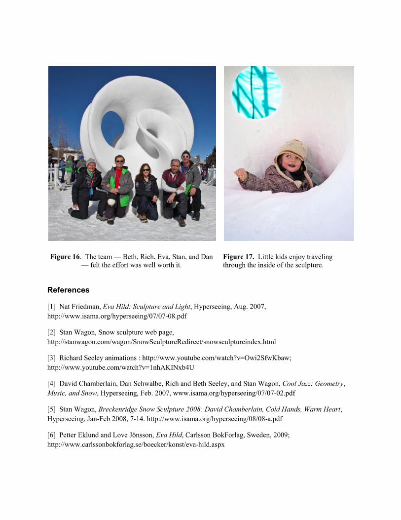
Figure 16. The team — Beth, Rich, Eva, Stan, and Dan — felt the effort was well worth it.
Figure 17. Little kids enjoy traveling through the inside of the sculpture.
References
[1] Nat Friedman, Eva Hild: Sculpture and Light, Hyperseeing, Aug. 2007, http://www.isama.org/hyperseeing/07/07-08.pdf
[2] Stan Wagon, Snow sculpture web page, http://stanwagon.com/wagon/SnowSculptureRedirect/snowsculptureindex.html
[3] Richard Seeley animations : http://www.youtube.com/watch?v=Owi2SfwKbaw; http://www.youtube.com/watch?v=1nhAKINxb4U
[4] David Chamberlain, Dan Schwalbe, Rich and Beth Seeley, and Stan Wagon, Cool Jazz: Geometry, Music, and Snow, Hyperseeing, Feb. 2007, www.isama.org/hyperseeing/07/07-02.pdf
[5] Stan Wagon, Breckenridge Snow Sculpture 2008: David Chamberlain, Cold Hands, Warm Heart, Hyperseeing, Jan-Feb 2008, 7-14. http://www.isama.org/hyperseeing/08/08-a.pdf
[6] Petter Eklund and Love Jönsson, Eva Hild, Carlsson BokForlag, Sweden, 2009; http://www.carlssonbokforlag.se/boecker/konst/eva-hild.aspx

Nicola Carrino: Costruttivo Metro Nat Friedman
[email protected] Introduction After seeing many historical mosaics on a recent trip to Italy, it was a fortuitous surprise to come upon the contemporary mosaic Costuttivo Metro by Nicola Carrino that is located in Rome at the Vittorio Emanuele metro stop. It consists of twenty basic geometric shapes bounded by straight lines or simple curves, as shown in Figure 1. Partial views are shown in Figures 2-4 and a selection of individual images with detail shots are shown in Figures 5-16. A dynamic feature of the mosaics is the emphasis on diagonal row constructions. The ranges of shapes and colors are particularly attractive.
Figure 1. Nicola Carrino, Costruttivo Metro, Mosaic, Rome, Italy, 1996
Figure 2. Costuttivo Metro, partial view.
Image 1 is a shape bounded by a lower straight line and a convex boundary curve on the left and top that intersects a boundary concave curve on the right. The inner tile colors are a range of reds with a variety of square shapes arranged on diagonals. There are also triangular shapes to allow for narrow curved regions that we will refer to as streamers. The streamers are very appealing and are an innovative construction of Carrino. The outer gray tiles are square shaped and also arranged on a diagonal.
Image 2 is a shape bounded by straight lines above and below. The right boundary is a convex shape consisting of three lines and the left boundary is a concave shape that can be thought of as the right boundary cut out of the left side. The inner tile shapes are squares of basically the same size arranged on diagonal rows with triangular shapes to allow for streamers. The square tiles are a lighter blue and the streamers are darker blue.
Nicola Carrino: Costruttivo MetroNat Friedman

Figure 3. Costruttivo Metro, partial view. Figure 4. Costruttivo Metro, partial view.
Figure 5. Costruttivo Metro, Image 1 Figure 6. Costruttivo Metro, Image 1, detail.
Figure 6. Costruttivo Metro, Image 2. Figure 7. Costruttivo Metro, Image 2, detail.

Figure 3. Costruttivo Metro, partial view. Figure 4. Costruttivo Metro, partial view.
Figure 5. Costruttivo Metro, Image 1 Figure 6. Costruttivo Metro, Image 1, detail.
Figure 6. Costruttivo Metro, Image 2. Figure 7. Costruttivo Metro, Image 2, detail.
Figure 8. Costruttivo Metro, Image 3 Figure 9. Costruttivo Metro, Image 3, detail.
Figure 9. Costruttivo Metro, Image 4 Figure 10. Costruttivo Metro, Image 4, detail.
Figure 11. Costruttivo Metro, Image 5. Figure 12. Costruttivo Metro, Image 5, detail.
The shape in image 3 in Figure 8 is similar to the shape in image 2 except the right and left boundaries are curves instead of being formed by three lines. The black streamers consist of

longer rows of squares that are larger then the squares that make up the shape between streamers. The outer gray region consists of diagonal rows of square tiles with no streamers.
Image 4 in Figure 9 consists of two triangular shapes just touching at lower corners, which is an effective touch. The colors of the tiles in the triangles are light and dark purple. Streamers occur in the triangles. The outer region consists of diagonal rows of light and dark gray squares with no streamers.
The shape in Image 5 in Figure 11 has horizontal straight line upper and lower boundaries and a diagonal straight line boundary on the left. The right boundary is a staircase. The colors of the square tiles of the inner shape are light and dark red with the tiles arranged in diagonal rows with no streamers. However, streamers occur in the outer region consisting of light and dark blue square tiles of varying size.
Figure 13. Costruttivo Metro, Image 6. Figure 14. Costruttivo Metro, Image 6, detail.
The shape in Image 6 in Figure 13 is bounded by vertical lines on the left and right bounded by the same S-curve above and below. The tiles are colored with a range of blues and there are a variety of wide and narrow streamers in the shape. The outer region consists of diagonal rows of grey square tiles with no streamers.
Summary
The above images display a variety of minimal geometric shapes with a maximal choice of colors and original inner detail within the shapes. As mentioned above, the basic diagonal row patterns are particularly appealing. For example, in Images 2 and 6, the blue diagonal streamers are reminiscent of flowing water. It is wonderful to see the ancient mosaic art form carried forward in the truly contemporary work Costruttivo Metro.
Hypersculpture:
Four Right Angles
Nat Friedman [email protected]
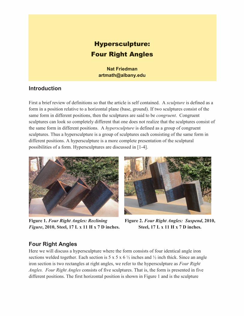
Introduction First a brief review of definitions so that the article is self contained. A sculpture is defined as a form in a position relative to a horizontal plane (base, ground). If two sculptures consist of the same form in different positions, then the sculptures are said to be congruent. Congruent sculptures can look so completely different that one does not realize that the sculptures consist of the same form in different positions. A hypersculpture is defined as a group of congruent sculptures. Thus a hypersculpture is a group of sculptures each consisting of the same form in different positions. A hypersculpture is a more complete presentation of the sculptural possibilities of a form. Hypersculptures are discussed in [1-4].
Four Right Angles Here we will discuss a hypersculpture where the form consists of four identical angle iron sections welded together. Each section is 5 x 5 x 6 ½ inches and ½ inch thick. Since an angle iron section is two rectangles at right angles, we refer to the hypersculpture as Four Right Angles. Four Right Angles consists of five sculptures. That is, the form is presented in five different positions. The first horizontal position is shown in Figure 1 and is the sculpture
Figure 1. Four Right Angles: Reclining Figure, 2010, Steel, 17 L x 11 H x 7 D inches.
Figure 2. Four Right Angles: Suspend, 2010, Steel, 17 L x 11 H x 7 D inches.
Hypersculpture: Four Right Angles

Reclining Figure. Reclining Figure was suggested by the sculpture Three Piece Reclining Figure Bridge Prop by Henry Moore, which may be viewed on Google. Reclining Figure appeared as a maquette Four Piece Reclining Form in Figure 16 in [5].
The second horizontal position is shown in Figure 2 and is the sculpture Suspend. Here the two end sections support the two middle sections which are suspended in midair.
The third horizontal position is shown in Figure 3 and is the sculpture Space, with reference to the central space bounded by the two middle sections. This view is essentially the top view of Suspend.
The first vertical position is shown in Figure 4 and is the sculpture Ascent, as the form is reminiscent of a rocket taking off.
The second vertical position is shown in Figure 5 and is the sculpture Cantilever, referring to the upper part cantilevered over the lower part. This position is the position of Ascent rotated slightly to the right and is a stable balanced position. We note that the sculpture is not balanced when standing on the other end section.
Role of Sections: Active, Supportive, or Both.
The form consists of four sections, which we will label A, B, C, and D, as in Figure 5 from top A to bottom D. The interesting point is how the role of each section varies from sculpture to sculpture. Referring to Cantilever in Figure 5, A on top is active, D on the bottom is supportive, and B and C could be described as both. The same can be said for Ascent in Figure 4. In Space in Figure 3, B and C in the center
Figure 3. Four Right Angles: Space, 2010, Steel, 17 L x 7 H x 11 D inches.
Figure 4. Four Right Angles: Ascent, 2010, Steel, 17 H x 11 W x 7 D Inches.

are active and A and D at the ends are supportive. The same can be said for Suspend in Figure 2. For Reclining Figure in Figure 1, D (on the left here) is active, C is supportive and B and A (on the right here) are both. We note that the role “both” can be quite subjective.
For a general hypersculpture where the form consists of separate components, one can discuss whether a component is active, supportive, or both in each sculpture. Thus one can see how a
component acts in each sculpture. This is a new topic in the discussion of sculptures that arises when considering hypersculptures.
References* [1] Nat Friedman, Hyperseeing, Hyperseeing, September, 2006. [2] Nat Friedman, Hypersculptures, Hyperseeing, May, 2007 ( Proceedings of ISAMA 2007). [3] Nat Friedman, Charles Ginnever: Giant Steps, Hyperseeing, Jan/Feb, 2008. [4] Nat Friedman, Giant Steps by Charles Ginnever, Hyperseeing, May/June 2008 (Proceedings of ISAMA 2008). [5] Nat Friedman, Geometric Sculptures Based on an Angle Iron Module,
Hyperseeing, Summer, 2010 (Proceedings of ISAMA 2010). *Past issues of Hyperseeing can be viewed at www.isama.org/hyperseeing
Figure 5. Four Right Angles: Cantilever, 2010, Steel, 17 H x 11 W x 7 D inches.

MALBEC
Gabriel Esquivel Participants: Design: Gabriel Esquivel, Chris Gassaway Fabrication: Ky Coffman, Matt Richardson, Jeffrey Quantz. Fabrication Consultant: Cody Davis
Introduction The digital fabrication tools used in project Malbec, included the digital modeling tools: Autodesk Maya and Rhino, the manufacturing software, MasterCAM, and a 3-axis CNC (Computer Numerical Control) machine. Material removal is the essential characteristic of subtractive fabrication, and is generally a CNC milling technique. The concept behind the project was the idea of a huge wine splash on the gallery wall.
Malbec addressed material experimentation with poly-urethane foam to produce expressive form. We strove for minimal design sacrifice by developing innovative fabrication techniques and assembly procedures which allowed us to find a way around the machine limitations. We were interested in how to create certain surface effects and increase material performance by
MALBEC
Gabriel Esquivel

combining the foam with additive materials including films, lacquers, and coatings. Malbec deals with issues such as architectural experience and it engages the scale of the human body. It can be perceived as an object as well as experienced as a sensate architectural environment. Malbec was designed to be a prototype for a digital storefront that uses the idea of rustication as its articulation. It was designed for the Storefront exhibition from The Neighborhood Design Center at The Ohio State University Urban Arts Space. November 4, 2009. Materials and Technological Resources Since this project was carried out from design to production, it was important to be critically aware of our available production tools, and material possibilities early on in the design process. The evaluation each software, hardware, and analog tool was crucial to the success of this project. Every tool has a purpose, but that purpose should be continually challenged to foster new techniques and more innovative design solutions. Our primary software resources were Autodesk Maya and Rhinoceros, both of which were used back and forth for the design and file preparations. Design Intent Malbec was designed to be a prototype for a non-transparent digital storefront. Its primary intention was not to be representational of an actual façade but rather an engage the scale of the human body in an architectural way and conjure certain emotional, sensational responses through its form, surface articulation and materiality. The design consists of an approximately 8’ by 8 ½’ area of wall panels and a 10’ by 3’ completely 3-dimensional “branch” structure. The panels
were designed to be flat on one side, where they attach to the wall, while the branch structure is suspended above an opening in the wall and must be hung from above. Figure 1 shows an elevation of the design relative to the scale of a human. Materials The material of choice was poly-urethane foam, which is a common choice that has been used for CNC milling. Poly-
urethane is more expensive than polystyrene but comes in a variety of different densities, typically in 2 pound increments with the higher the density of the foam, the higher the strength. It also comes in 4’ by 8’ sheets with varying thickness, which allowed us to eliminate the step of laminating sheets together. We decided to use primarily 2 lb. density foam for the wall panels but 10 pound density for the “neck”, or beginning of the sculpted 3-dimensional piece where we anticipated there would be weakness.
FIGURE 1. Front view, dimensioned elevation of the overall design.
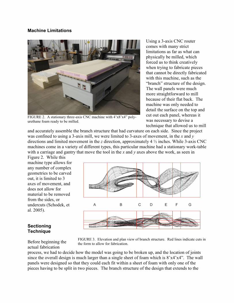
Machine Limitations
Using a 3-axis CNC router comes with many strict limitations as far as what can physically be milled, which forced us to think creatively when trying to fabricate pieces that cannot be directly fabricated with this machine, such as the “branch” structure of the design. The wall panels were much more straightforward to mill because of their flat back. The machine was only needed to detail the surface on the top and cut out each panel, whereas it was necessary to devise a technique that allowed us to mill
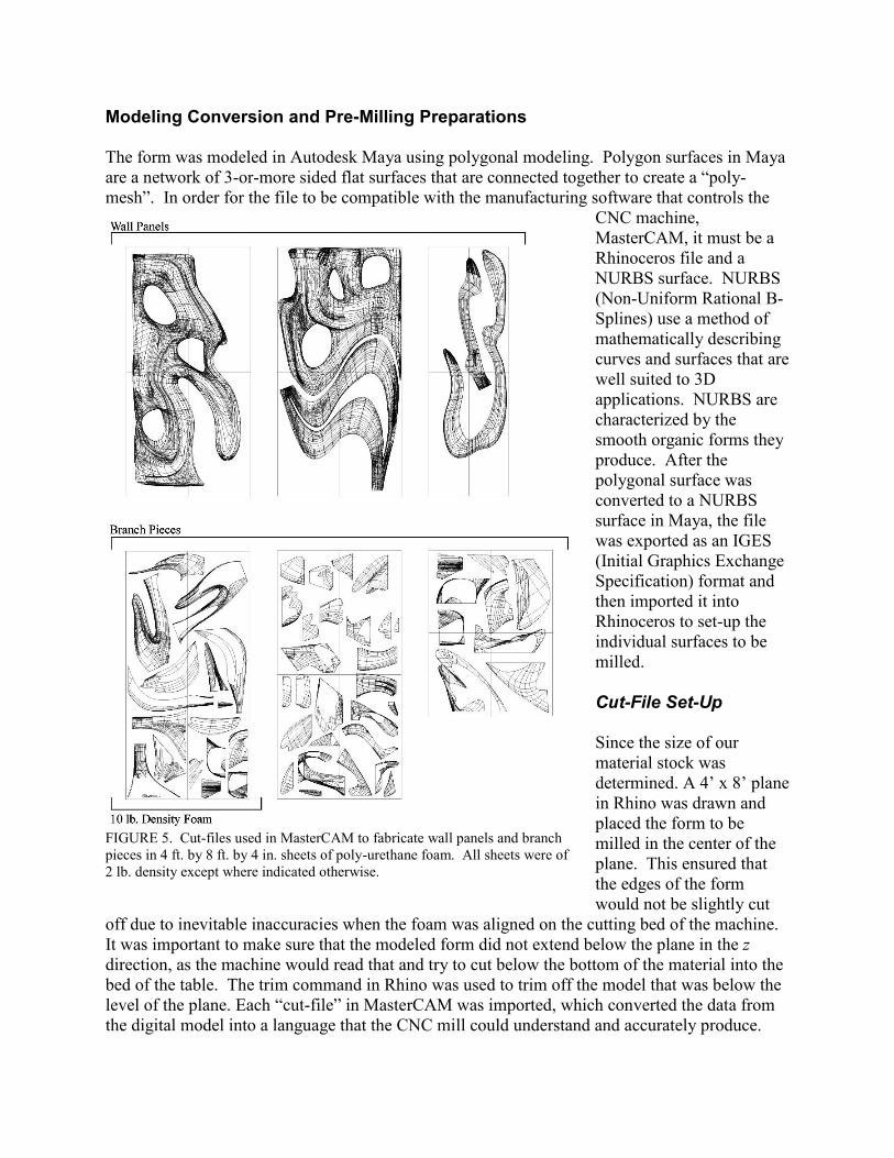
and accurately assemble the branch structure that had curvature on each side. Since the project was confined to using a 3-axis mill, we were limited to 3-axes of movement, in the x and y directions and limited movement in the z direction, approximately 4 ½ inches. While 3-axis CNC machines come in a variety of different types, this particular machine had a stationary work-table with a carriage and gantry that move the tool in the x and y axes above the work, as seen in Figure 2. While this machine type allows for any number of complex geometries to be carved out, it is limited to 3 axes of movement, and does not allow for material to be removed from the sides, or undercuts (Schodek, et al. 2005). Sectioning Technique Before beginning the actual fabrication process, we had to decide how the model was going to be broken up, and the location of joints since the overall design is much larger than a single sheet of foam which is 8’x4’x4”. The wall panels were designed so that they could each fit within a sheet of foam with only one of the pieces having to be split in two pieces. The branch structure of the design that extends to the
FIGURE 2. A stationary three-axis CNC machine with 4’x8’x4” poly- urethane foam ready to be milled.
FIGURE 3. Elevation and plan view of branch structure. Red lines indicate cuts in the form to allow for fabrication.

right of the paneled wall pieces was designed to be completely 3-dimensional, a total sculpture with curvature on each side and perforations. Since a 3-axis mill does not have the ability to make undercuts, the biggest challenge was to figure out a technique that allowed the piece to be fabricated. A sectioning technique was used to split the piece into separate horizontal sections since the overall length was longer than 8 feet. It was then further sectioned vertically with each sectioned piece not extending higher than 4 inches, due to the height of the foam stock. With this technique, it was possible to mill many small pieces of the overall form that fit together much like a giant jigsaw puzzle. The red lines in Figure 3 show where the form was cut in both elevation view and plan view. Undercuts were not completely unavoidable but we tried to avoid them as much as possible, and the parts where undercuts could not be avoided had to be sanded by hand to approximate the geometry. Figure 4 shows an exploded axonometric of the overall branch structures and the separate pieces that make up the whole. By organizing the horizontal sections alpha-
numerically, it was possible to assemble the pieces of each section separately before combining the separate sections.
FIGURE 4. Exploded axonometric of overall branch structure. Shows sectioning technique of splitting branch into 7 sections horizontally (A-G) and then slicing those sections into 4 inch high pieces.
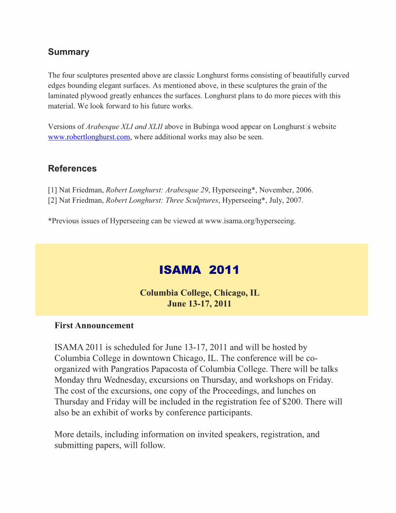
Modeling Conversion and Pre-Milling Preparations The form was modeled in Autodesk Maya using polygonal modeling. Polygon surfaces in Maya are a network of 3-or-more sided flat surfaces that are connected together to create a “poly-mesh”. In order for the file to be compatible with the manufacturing software that controls the
CNC machine, MasterCAM, it must be a Rhinoceros file and a NURBS surface. NURBS (Non-Uniform Rational B-Splines) use a method of mathematically describing curves and surfaces that are well suited to 3D applications. NURBS are characterized by the smooth organic forms they produce. After the polygonal surface was converted to a NURBS surface in Maya, the file was exported as an IGES (Initial Graphics Exchange Specification) format and then imported it into Rhinoceros to set-up the individual surfaces to be milled. Cut-File Set-Up Since the size of our material stock was determined. A 4’ x 8’ plane in Rhino was drawn and placed the form to be milled in the center of the plane. This ensured that the edges of the form would not be slightly cut
off due to inevitable inaccuracies when the foam was aligned on the cutting bed of the machine. It was important to make sure that the modeled form did not extend below the plane in the z direction, as the machine would read that and try to cut below the bottom of the material into the bed of the table. The trim command in Rhino was used to trim off the model that was below the level of the plane. Each “cut-file” in MasterCAM was imported, which converted the data from the digital model into a language that the CNC mill could understand and accurately produce.
FIGURE 5. Cut-files used in MasterCAM to fabricate wall panels and branch pieces in 4 ft. by 8 ft. by 4 in. sheets of poly-urethane foam. All sheets were of 2 lb. density except where indicated otherwise.

Figure 5 shows the actual cut-files that were used to in MasterCAM to fabricate the entire design.
Material Set-Up Before starting the milling process it was necessary to set up the actual material stock (4’x8’x4” foam) on the cutting table, put in the specified bit, and then actually tell the machine where 0, 0, 0 is by “touching down” the bit. There was a smooth composite board or masonite, i.e. “sacrifice board” so that the bit would not be ruined if it for some reason went below our material stock. Because the foam used is extremely light-weight (2 pound density) a way to keep the foam from moving during the milling process was required. The chosen tape was double-sided carpet tape, which was stronger and worked the best. Strips of the tape were laid down length-wise on the composite board with 3 inch to 4 inch spacing between the strips and placed the foam on top. Scrap polystyrene “holders” were drilled around the perimeter of the foam to also help keep the foam from moving. Milling Depending on the size of the form to be milled, the actual milling process usually took about 3-4 hours for the rough-cut and about 2 or more hours for the finish-cut. It was extremely important that the foam not move during the rough-cut, which is the term used to describe the first round of cutting that essentially gets the rough overall form cut out from the block of foam; the machine typically has ½” to 1” step-downs during the rough cut. The finish-cut is where the machine goes back and refines the surface of the form with much smaller step-downs and results in the smooth finished form. Finishing The finishing process began as soon as each piece was done milling and another was started. For the large panels, finishing was much more simple than for the sculpted 3-dimensional pieces that
FIGURE 6. Photographs showing the first, second, third, and final step-down of the rough cut, a detail of the rough-cut and the finish-cut

had to be joined together first. The finishing process consisted of sanding, lacquering, application of joint compound, more sanding, assembling and finally painting. One of the most important steps was to have a system of organization for the 3- dimensional pieces so that we could know which pieces went together and how they fit. Organization For the 3-dimensional sculpted pieces, there was a good deal of coordination back and forth between the computer model and the milling table for the arrangement of the pieces. The sculpted piece that was sectioned in Rhino was labeled A, B, C, D, E, F, and G, according to the corresponding horizontal segments. Then each segmented portion, sectioned in 4 inch increments, was laid out on the milling stock and labeled according to which section they belonged to (A-G). When the milling of these panels was finished, the pieces were taken directly off the cutting table and grouped on tables according to their appropriate groups, denoted by pieces of tape identifying the
lettered groups. The appropriate configurations of the pieces within the groups were determined by examining the computer model. Assembly The method that was outlined above was used for the majority of the form, including the wall panels, but a slightly altered method was used for the sectioned pieces that had to be assembled together as well. For these pieces, we first glued the pieces together according to their segmented categories (labeled A through G) using an epoxy resin and hardener. After the glued pieces had dried, we sanded the complete forms to achieve a more uniform smoothness, and even out the joints. The lacquer, joint compound, sanding method was then used on each entire assembled form. After each assembled form was dry we began to piece together the separate segmented groups. Since the entire length of the branch was over 8 feet long, we decided to join all of the pieces into two separate branches rather than one large one to allow for easier
FIGURE 17. Compound application.
FIGURE 8. Assembled section of the branch structure that has not yet been sanded or finished.

transportation, and installation. Because this sculptural piece would be suspended over an opening by wires, the connections needed to be very strong so that the branch would not break at the weak joints. For the weaker joints, especially those where the 10 pound density foam had to be joined to the 2 pound foam, we used metal dowel rods to hold the pieces together. We first drilled holes through the two separate pieces and inserted the metal rods, coated in epoxy resin and hardener, into them at opposing angles to add strength and stability. In some cases, such as joining pieces that were both 2 pound density, we used shorter wooden dowels instead. Painting The painting of the wall panels and branch structure was done by a professional automotive paint shop. This was the final finishing technique used and was successful in giving the foam the glossy effect as seen in the close-up of the surface in Figure 10. Overall, the joint compound was a sufficient base for the automotive paint finish, although it tended to absorb the paint in certain areas which resulted in a less glossy finish it some parts. We predict that using automotive grade putty such as Bondo would help to solve this problem. References
Boone, E., Buente, A., Brockmeyer, E., & Perry, K. (n.d.). Thesis Proposal. Retrieved October 25, 2009, from www.projectione.com Iwamoto, L. (2009). Digital Fabrications Architectural and Material Techniques. New York: Princeton Architectural P.
FIGURE 9. Photographs showing our method of joined pieces together. With the 10 pound density foam, metal dowel rods were used and with the 2 pound density foam wooden dowels were used.

Kolarevic, B., & Klinger, K. R. (2008). Manufacturing/Material Effects. In B. Kolarevic (Author), Manufacturing Material Effects Rethinking Design and Making in Architecture (pp. 5-24). New York: Routledge. Mitchell, W. J. (2008). [Foreword]. In Expressive Form: A Conceptual Approach to Computational Design (pp. Vii-Viii). New York: Spon P. Mori, T. (Ed.). (2002). Immaterial/ultramaterial architecture, design, and materials. Cambridge, Mass: Harvard Design School in association with George Braziller. Moussavi, F., & Kubo, M. (2006). The Function of Ornament. Barcelona: Actar. Reffat, R. M. (2008). Digital Architecture and Reforming the Built Environment. Journal of Architectural and Planning Research, 25(2), 118-129. Retrieved October 18, 2008, from Wilson. Schodek, D., Bechthold, M., Griggs, K., Martin Kao, K., & Steinberg, M. (2005). Digital design and manufacturing CAD/CAM applications in architecture and design. Hoboken: John Wiley & Sons. Speaks, M. (2002, January). Design Intelligence and the New Economy. Architectural Record, 72-76. Retrieved September 19, 2009, from Academic Search Complete. Spina, Marcelo, and Georgina Huljich. "Ouch or Ooooh? On "Matters of Sensation"" Ed. Todd Gannon. Log 17. [S.l.]: Anyonr Corp, 2009. 93-104. Print. Spuybroek, Lars. Research & Design: The Architecture of Variation. New York: Thames & Hudson, 2009. Print. Steele, B. (2008). Prototyping Architecture's Future, Again [Foreword]. In Manufacturing/Material Effects (pp. 1-4). New York, NY: Routledge. Terzidis, K. (2008). Expressive Form: A Conceptual Approach to Computational Design. New York: Spon P.
FIGURE 10 Detail of one of the wall panels, finished with automotive paint.

Robert Longhurst: Recent Sculptures
Nat Friedman
Introduction Robert Longhurst is an abstract sculptor whose beautiful wood carvings are in a class by themselves [1-2]. Recently he was commissioned by the Ritz Carleton in Phoenix, AZ to carve four works and he used marine plywood for the first time. The grain of the layers of laminated plywood result in striking surface designs as seen in Figures 1-4.
Figure 1. Robert Longhurst, Arabesque XLI, 2010, 20Ó H x 20Ó w x 12Ó D, Occume Mahogoney plywood, Black Granite base, 3-1/2Ó H x 10Ó Diameter.
Figure 2. Robert Longhurst, Arabesque XLVII, 2010, 42Ó H x 10Ó W x 13Ó D, Occume mahogoney plywood, Black Granite base, 4Ó H x 8Ó Diameter.
Robert Longhurst: Recent Sculptures

Arabesque XLI is an approximate circular form with three curves almost touching. One curve is large relative to two smaller curves. The surface consists of three different parts between curves, each with hyperbolic curvature. Arabesque XVLII is a vertical form with two narrow crossing bands connecting upper and lower doubly curved wave forms. The sculpture has half turn rotational symmetry about a central vertical axis. A version in Bubinga wood is discussed in [2].
Figure 3. Robert Longhurst, Arabesque XLII, 2010, 30”H x 20”W x 18”D, Occume Mahogoney plywood, Black Granite base, 4”H x 10”Diameter.
Figure 4. Robert Longhurst, Arabesque XLIII, 2010, 42”H x 13”W x 14”D, Occume Mahogany plywood, Black granite base, 4”H x 8”Diameter.
Arabesque XLII is an approximate oval form with a beautiful combination of curved edges and wave forms with hyperbolic surfaces bounded by the edges. The sculpture has half turn rotational symmetry about a central horizontal axis (from front to back).
Arabesque XLIII is a vertical form consisting of two wide bands connecting curved forms above and below. The sculpture has half turn rotational symmetry about a central horizontal axis (from left to right).
Arabesque XLI is an approximate circular form with three curves almost touching. One curve is large relative to two smaller curves. The surface consists of three different parts between curves, each with hyperbolic curvature. Arabesque XVLII is a vertical form with two narrow crossing bands connecting upper and lower doubly curved wave forms. The sculpture has half turn rotational symmetry about a central vertical axis. A version in Bubinga wood is discussed in [2].
Figure 3. Robert Longhurst, Arabesque XLII, 2010, 30Ó H x 20Ó W x 18Ó D, Occume Mahogoney plywood, Black Granite base, 4Ó H x 10Ó Diameter.
Figure 4. Robert Longhurst, Arabesque XLIII, 2010, 42Ó H x 13Ó W x 14Ó D, Occume Mahogany plywood, Black granite base, 4Ó H x 8Ó Diameter.
Arabesque XLII is an approximate oval form with a beautiful combination of curved edges and wave forms with hyperbolic surfaces bounded by the edges. The sculpture has half turn rotational symmetry about a central horizontal axis (from front to back).
Arabesque XLIII is a vertical form consisting of two wide bands connecting curved forms above and below. The sculpture has half turn rotational symmetry about a central horizontal axis (from left to right).
Summary The four sculptures presented above are classic Longhurst forms consisting of beautifully curved edges bounding elegant surfaces. As mentioned above, in these sculptures the grain of the laminated plywood greatly enhances the surfaces. Longhurst plans to do more pieces with this material. We look forward to his future works. Versions of Arabesque XLI and XLII above in Bubinga wood appear on LonghurstÕ s website www.robertlonghurst.com, where additional works may also be seen. References [1] Nat Friedman, Robert Longhurst: Arabesque 29, Hyperseeing*, November, 2006. [2] Nat Friedman, Robert Longhurst: Three Sculptures, Hyperseeing*, July, 2007. *Previous issues of Hyperseeing can be viewed at www.isama.org/hyperseeing.
ISAMA 2011
Columbia College, Chicago, ILJune 13-17, 2011
First Announcement
ISAMA 2011 is scheduled for June 13-17, 2011 and will be hosted by Columbia College in downtown Chicago, IL. The conference will be co-organized with Pangratios Papacosta of Columbia College. There will be talks Monday thru Wednesday, excursions on Thursday, and workshops on Friday. The cost of the excursions, one copy of the Proceedings, and lunches on Thursday and Friday will be included in the registration fee of $200. There will also be an exhibit of works by conference participants.
More details, including information on invited speakers, registration, and submitting papers, will follow.

JMM 2011 Prize Winners Nat Friedman
Congratulations to the prize winners in the Joint Mathematics Meetings 2011 Exhibit. They are First Prize: Margaret Kepner, Second Prize: Carlo Séquin, Third Prize: Anne Burns. Their works are shown below. Ê
Ê
ÊMargaret Kepner, Magic Square Study, Archival inkjet print, 18Ó x 18Ó, 2010.
Ê
ÊÊ
Carlo Séquin, Torus Knot (5, 3), Bronze with silver patina, 10Ó x 8Ó x 16 Ó, 2010.
ÊÊ
Anne Burns, Circles on Orthogonal Circles, Digital print, 12Ó x 16Ó, 20 10
For details about the artists and descriptions of works, see the complete exhibit at http:jmm.submit.bridgesmathart.org/ Ê
JMM 2011 Prize WinnersNat Friedman

JMM 2011 Prize Winners Nat Friedman
Congratulations to the prize winners in the Joint Mathematics Meetings 2011 Exhibit. They are First Prize: Margaret Kepner, Second Prize: Carlo Séquin, Third Prize: Anne Burns. Their works are shown below. Ê
Ê
ÊMargaret Kepner, Magic Square Study, Archival inkjet print, 18Ó x 18Ó, 2010.
Ê
ÊÊ
Carlo Séquin, Torus Knot (5, 3), Bronze with silver patina, 10Ó x 8Ó x 16Ó, 2010.
ÊÊ
Anne Burns, Circles on Orthogonal Circles, Digital print, 12Ó x 16Ó, 2 010
For details about the artists and descriptions of works, see the complete exhibit at http:jmm.submit.bridgesmathart.org/ Ê


ISAMA 2011
Columbia College, Chicago, ILJune 13-17, 2011
First Announcement
ISAMA 2011 is scheduled for June 13-17, 2011 and will be hosted by Columbia College in downtown Chicago, IL. The conference will be co-organized with Pangratios Papacosta of Columbia College. There will be talks Monday thru Wednesday, excursions on Thursday, and workshops on Friday. The cost of the excursions, one copy of the Proceedings, and lunches on Thursday and Friday will be included in the registration fee of $200. There will also be an exhibit of works by conference participants.
More details, including information on invited speakers, registration, and submitting papers, will follow.
Sculpture Generator
Mehrdad Garousi Freelance fractal artist, painter and photographer
No. 153, Second floor, Block #14, Maskan Apartments, Kashani Ave,
Hamadan, Iran E-mail: [email protected]
http://mehrdadart.deviantart.com
I learned about the software SculptGen when reading a tutorial article entitled # Carlo S# quin# s Sculpture Generator 1 # [1], written by Nat Friedman, in Hyperseeing [1]. I decided to explore this software and put plenty of time in different periods to experience diverse inspirations. I can say that it is a very interesting and fast processing software. Before knowing this software, I had started working with TopMod [2,10] for a while. SculptGen as another useful mathematical software provides us with another subset of mathematical shapes and sculptures which are made up of minimal surfaces. However, due to the small number of controllers in SculptGen, TopMod# s following might find fewer possibilities in comparison to TopMod. But, these are two pieces of software belonging to different areas with their own limitations and advantages.
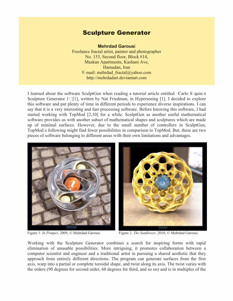
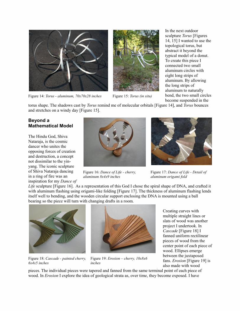
Working with the Sculpture Generator combines a search for inspiring forms with rapid elimination of unusable possibilities. More intriguing, it promotes collaboration between a computer scientist and engineer and a traditional artist in pursuing a shared aesthetic that they approach from entirely different directions. The program can generate surfaces from the first axis, warp into a partial or complete toroidal shape, and twist along its axis. The twist varies with the orders (90 degrees for second order, 60 degrees for third, and so on) and is in multiples of the
Figure 1. In Pompei, 2009, © Mehrdad Garousi. Figure 2. The Sunflower, 2010, © Mehrdad Garousi.
Sculpture Generator
Mehrdad GarousiFreelance fractal artist, painter and photographer
No. 153, Second floor, Block #14,Maskan Apartments, Kashani Ave,
Hamadan, IranE-mail: [email protected]
http://mehrdadart.deviantart.com

angle required to close the toroidal shape of an odd number of stories. A user can map textures to a virtual sculpture, applying various colors or realistic materials to surfaces; rotate the sculpture for viewing at any angle; and position it against different backgrounds. Since the program aims for real-time interactivity, users can control levels of detail and turn textures on and off as needed. The virtual model can be viewed as a single image or stereoscopically [3].
I suggest all mathematical artists give this wonderful software a try to see what they can create with minimal surfaces. To have a good tutorial in this regard I recommend studying Nat Friedman’s article [1].
Figure 5. Continuity, 2010, © Mehrdad Garousi. Figure 6. Golden Star, 2010, © Mehrdad Garousi.
Figure 3. Playground Slides, 2010, © Mehrdad Garousi.
Figure 4. Refuge, 2010, © Mehrdad Garousi.
I myself create basic shapes in SculptGen and having changed .stl file formats to .obj in MeshLab [4], make realistic renders of them in Modo [5]. This way they appear as realistic shapes in everyday life. I also have made some mathematical animations by SculptGen. Some mysterious examples of them are Self-Conversion [6], presented at the SIAF Symposium 2010 [7], and Seven Pointed Star [8], presented at GA2010 [9]. Staring at them,you could have a better realization of the properties of shapes created in SculptGen. A selection of my renderings are presented below. Sculpture Generator can be downloaded at http://www.cs.berkeley.edu/~sequin/GEN/
Figure 7. Vortex, 2010, © Mehrdad Garousi. Figure 8. Flower, 2010, © Mehrdad Garousi.
References: [1] Friedman, N., 2008, Carlo Sèquin’s Sculpture Generator 1, Hyperseeing, Jul-Aug 2008. [2] "TopMod: Topological Mesh Modeler" Concept Development: E. Akleman; Software Architect: V. Srinivasan. Contributors: E. Lendreneau, Z. Melek, E. Mandal, C. Evrenosoglu, X. Bei, P. Edmundson, F. Eryoldas. Released in November 2005. http://www.topmod3d.org/. [3] Abouaf, J., 1998, Variations on Perfection: The Séquin-Collins Sculpture Generator, IEEE Computer Graphics and Applications, November 1998, pp. 15-20. [4] http://meshlab.sourceforge.net/ . [5] http://www.luxology.com/modo/ . [6] http://mehrdadart.deviantart.com/art/Self-Conversion-149587079?q=&qo= . [7] SIAF Symposium 2010 (Sydney International Animation Festival Symposium), 24 September, University of Technology, Sydney, Australia. [8] http://mehrdadart.deviantart.com/art/Seven-Pointed-Star-170069107?q=gallery%3Amehrdadart%2F271295&qo=22 . [9] GA2010 (13th Generative Art Conference), 15, 16, 17 December, 2010, Politecnico di Milano University, Milan, Italy. [10] E. Akleman, V. Srinivasan, J. Chen, D. Morris, S. Tett, "TopMod3D: An Interactive Topological Mesh Modeler" Proceedings of Computer Graphics International' 2008 (CGI'08),

From Chemistry to Art
Susan Van der Eb Greene Research Analytical Chemist, retired
Richmond, VA E-mail: [email protected]
Abstract My career in chemistry laid the foundation for my excitement in visualizing the microscopic, molecular, and subatomic structures that define what we see at the macroscopic level in Nature. Mathematics assisted my visualization process and the evolving mathematics that models the cosmos continues to inspire my work.
Figure 1: Mobius Strip - butternut wood, 8x4x3 inches
Figure 2: Mobius Strip - laminated wood, 4x3x2 inches
Introduction As a young child I was fascinated by questions that involved snow flake patterns cut from folded paper. Being asked to draw the cut pattern before the folded paper was opened intrigued me. I also enjoyed questions that asked where the sweater label would be found if one took off a sweater with the label on the inside at the back of the neck, turned the sweater inside out, rotated it 180 degrees, and put the sweater on again. My mind enjoyed visualizing forms and turning them in space. I attended a Waldorf School for my middle school years, where the educational philosophy encouraged imagination and fostered creative and analytical thinking. It was there I was introduced to wood carving and conceptualization of form continued to attract my attention. Understanding how the 3-dimensional structure of a bio-molecule will determine its function was the main reason I was drawn to chemistry. My specialty was liquid chromatography. I developed separation methods that characterized chiral molecules. Chiral molecules have identical chemical formulae, but in 3-
From Chemistry to Art
Susan Van der Eb GreeneResearch Analytical Chemist, retired
Richmond, VAE-mail: [email protected]

From Chemistry to Art
Susan Van der Eb Greene Research Analytical Chemist, retired
Richmond, VA E-mail: [email protected]
Abstract My career in chemistry laid the foundation for my excitement in visualizing the microscopic, molecular, and subatomic structures that define what we see at the macroscopic level in Nature. Mathematics assisted my visualization process and the evolving mathematics that models the cosmos continues to inspire my work.
Figure 1: Mobius Strip - butternut wood, 8x4x3 inches
Figure 2: Mobius Strip - laminated wood, 4x3x2 inches
Introduction As a young child I was fascinated by questions that involved snow flake patterns cut from folded paper. Being asked to draw the cut pattern before the folded paper was opened intrigued me. I also enjoyed questions that asked where the sweater label would be found if one took off a sweater with the label on the inside at the back of the neck, turned the sweater inside out, rotated it 180 degrees, and put the sweater on again. My mind enjoyed visualizing forms and turning them in space. I attended a Waldorf School for my middle school years, where the educational philosophy encouraged imagination and fostered creative and analytical thinking. It was there I was introduced to wood carving and conceptualization of form continued to attract my attention. Understanding how the 3-dimensional structure of a bio-molecule will determine its function was the main reason I was drawn to chemistry. My specialty was liquid chromatography. I developed separation methods that characterized chiral molecules. Chiral molecules have identical chemical formulae, but in 3-
dimensional space they are mirror images. Because of their different orientation in space, as pharmaceutical drugs they produce different responses in a patient. I also used size exclusion chromatography with multiple detectors that permitted the 3-dimensional characterization of polymers. Understanding the spacial configuration of a molecule is critical because 3-dimensional architecture relates directly to chemical performance. My interest in wood carving lay dormant until I took an early retirement package from chemical research in 2001. At this stage of my life when I am free of the lock-step of the corporate world, I have time to explore more fully areas that were for years on the edge of my plate. I began by taking furniture making classes, then sculpture courses at Virginia Commonwealth University. Topological Surfaces: Wood Carvings My wood carvings began with topological surfaces I had learned about as a child: Mobius Strip [Figure 1], Mobius Strip [Figure 2], and Trefoil Knot [Figure 3]. I also became intrigued by forms whose topological shape I could visualize but that I wanted to understand better by releasing the form from a block of wood: Genus 2 Orientable Manifold [Figure 4]. For my wood carvings I want the surface and wood grain to encourage viewers to hold the piece, so they too can then share my hands-on understanding.
Figure 3: Trefoil Knot – cherry, 8x8x4 inches
Figure 4: Genus 2 Orientable Manifold - mahogany, 7x5x4 inches
I soon began to look beyond model making, as I wanted to have mathematics and science inform my designs rather than generate them. Furniture My furniture usually has an element of sculpture in the design. When designing a glass-topped Spiral Leg Table [Figure 5] I employed 3-D Studio Max, a computer graphics package. The logarithmic spiral design for the legs was modeled first in this computer graphics package [Figure 6]. Similar to the designer molecules synthetic chemists create, I could turn my table in virtual space on the computer and decide if the proportion and orientation of the legs was appropriate. I was pleased to see that the aerial view of the spiral legs reminded me of a Celtic design, which also employs fundamental mathematical curves.

Figure 5: Spiral Leg Table Ð cherry, 24x24x17 inches
Figure 6 - Visualizing the logarithmic spiral leg design using 3-D Studio Max, a modeling, rendering, computer graphics package
Next I wanted to make a table with more linear geometry, so I designed a Hexagonal Table with two tiers of glass [Figure 7]. The two levels of glass permit one to place an object in the volume defined by the two parallel hexagonal surfaces. In this table, as in much of my work, a characteristic aesthetic begins to come into focus. The geometry of my sculptures and furniture changes as the viewer moves around the object. I realize that I enjoy playing tricks on the eye in my designs. For example, when two of the legs of the Hexagonal Table are aligned, the piece appears to be off center and lacking a
stabilizing leg [Figure 8]. The placement of the legs in the center of three alternating sides of the hexagons, rather than at three alternating vertices, contributes to this visual confusion.
Figure 7: Hexagonal Side Table Ð cherry, 13x14x23 inches
Figure 8: Hexagonal Side Table - Visual alignment of 2 legs

Outdoor Sculptures Soon I considered sculpture for outdoor settings. Aluminum became my material of choice because it is light weight, withstands weather changes well, and has a modern, reflective finish that plays with light. My first outdoor piece was Seagulls [Figure 9]. Wind, or the viewer changing position, makes the positive and negative spaces that are an integral part of the suspended birds, change. The abstracted bird forms appear to move within the flock and the flock takes on a life of its own.
Figure 9: Seagulls (in situ) - aluminum, 8x6x4 feet
Figure 10: 3D Yin-Yang maquette – spruce laminates, 3x2x2 feet
Figure 11: 3D Yin-Yang maquette – plastic strapping, 5x5x3 inches
In our symbol-laden culture it is common to see 2-dimensional yin-yang designs, representations of complementary opposites. I decided to create a 3-dimensional yin-yang outdoor sculpture and began with two maquettes for possible designs [Figures 10, 11]. For the outdoor sculpture I selected the second maquette [Figure 11], because structurally it would work well with aluminum. It was also a more simplified form that would permit the viewer to see more of the environment in and around the piece. I named the final piece Reciprocal [Figures 12, 13].
Figure 12: Reciprocal ( in situ) – aluminum, 32x28x42 inches
Figure 13: Reciprocal - More views
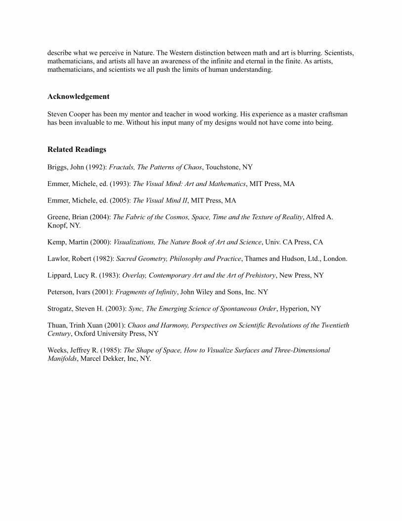
In the next outdoor sculpture Torus [Figures 14, 15] I wanted to use the topological torus, but abstract it beyond the typical model of a donut. To create this piece I connected two small aluminum circles with eight long strips of aluminum. By allowing the long strips of aluminum to naturally bend, the two small circles become suspended in the
torus shape. The shadows cast by Torus remind me of molecular orbitals [Figure 14], and Torus bounces and stretches on a windy day [Figure 15]. Beyond a Mathematical Model The Hindu God, Shiva Nataraja, is the cosmic dancer who unites the opposing forces of creation and destruction, a concept not dissimilar to the yin-yang. The iconic sculpture of Shiva Nataraja dancing in a ring of fire was an inspiration for my Dance of Life sculpture [Figure 16]. As a representation of this God I chose the spiral shape of DNA, and crafted it with aluminum flashing using origami-like folding [Figure 17]. The thickness of aluminum flashing lends itself well to bending, and the wooden circular support enclosing the DNA is mounted using a ball bearing so the piece will turn with changing drafts in a room.
Creating curves with multiple straight lines or slats of wood was another project I undertook. In Cascade [Figure 18] I fanned uniform rectilinear pieces of wood from the center point of each piece of wood. Ellipses emerge between the juxtaposed fans. Erosion [Figure 19] is also made with wood
pieces. The individual pieces were tapered and fanned from the same terminal point of each piece of wood. In Erosion I explore the idea of geological strata as, over time, they become exposed. I have
Figure 14: Torus - aluminum, 70x70x28 inches Figure 15: Torus (in situ)
Figure 16: Dance of Life - cherry, aluminum 8x4x9 inches
Figure 17: Dance of Life - Detail of aluminum origami fold
Figure 18: Cascade - painted cherry, 6x4x5 inches
Figure 19: Erosion – cherry, 10x8x6 inches

alluded to the effect of erosion with the chiseled and stained section on one sloping surface of the piece. One idea leads to the next, and I then ventured into the mind bending concept of worm holes. How would I represent this concept in a 3-dimensional universe? Cosmic Worm Hole [Figure 20] was my attempt, and I did so using a tetrahedron that has curved opposite edges with a linear channel that pierces two faces. Spirit Boat [Figure 21] is a more fanciful piece referencing my interpretation of a worm hole. It employs a compound curve for the center element. With this piece I learned that wood does not easily bend in opposite directions in the same region.
Figure 20: Cosmic Worm Hole - cedar, 4x4x4 inches Figure 21: Spirit Boat - exotic wood laminates, 18x8x7
inches Conclusions and Reflections With hindsight, transitioning from the analytical chemist’s research bench to sculpture and fine furniture has permitted me to continue pursuing the aspects of science that excited me. In both arenas I use my hands, experiment, and problem solve. I visualize forms moving in three-dimensional space, use technology and computers, and my understanding of material chemistry. The general public now has access to images from outer space and electron micrographs that elucidate crystalline structure and individual cell organelles. Atomic force microscopy presents the shapes of individual atoms and molecules and we can see the trails of subatomic particles formed in the large hadron collider. These and similar images are readily accessible on-line and in other digital media. Because of this increased exposure to images from science and mathematics the viewer can embrace the forms mathematicians and scientist encounter in their everyday work. As part of my interest in science and art, I sought out like-minded individuals. Five of us met through the sculpture department at Virginia Commonwealth University. We formed an artist group and named ourselves ComplexUs. All five artists have, or have had, either a career in science, or training in math and science. All five of us have “crossed over from the dark side,” from science and math to being professional artists. This summer (2010) the American Association for the Advancement of Science exhibited our art in their headquarters gallery in Washington, DC. http://www.aaas.org/news/releases/2010/0511art_exhibit?sa_campaign=Internal_Ads/AAAS/AAAS_News/2010-05-11/jump_page I have come to appreciate my pursuit of truth and beauty. Perhaps that grounding comes from my enjoyment of the abstractions used in mathematics and science, where elegant models are created to
describe what we perceive in Nature. The Western distinction between math and art is blurring. Scientists, mathematicians, and artists all have an awareness of the infinite and eternal in the finite. As artists, mathematicians, and scientists we all push the limits of human understanding. Acknowledgement Steven Cooper has been my mentor and teacher in wood working. His experience as a master craftsman has been invaluable to me. Without his input many of my designs would not have come into being. Related Readings Briggs, John (1992): Fractals, The Patterns of Chaos, Touchstone, NY Emmer, Michele, ed. (1993): The Visual Mind: Art and Mathematics, MIT Press, MA Emmer, Michele, ed. (2005): The Visual Mind II, MIT Press, MA Greene, Brian (2004): The Fabric of the Cosmos, Space, Time and the Texture of Reality, Alfred A. Knopf, NY. Kemp, Martin (2000): Visualizations, The Nature Book of Art and Science, Univ. CA Press, CA Lawlor, Robert (1982): Sacred Geometry, Philosophy and Practice, Thames and Hudson, Ltd., London. Lippard, Lucy R. (1983): Overlay, Contemporary Art and the Art of Prehistory, New Press, NY Peterson, Ivars (2001): Fragments of Infinity, John Wiley and Sons, Inc. NY Strogatz, Steven H. (2003): Sync, The Emerging Science of Spontaneous Order, Hyperion, NY Thuan, Trinh Xuan (2001): Chaos and Harmony, Perspectives on Scientific Revolutions of the Twentieth Century, Oxford University Press, NY Weeks, Jeffrey R. (1985): The Shape of Space, How to Visualize Surfaces and Three-Dimensional Manifolds, Marcel Dekker, Inc, NY.

A Graphics Researcher From 15th CenturyContributions of Jan Van Eyck
Ergun Akleman
Abstract
In this paper, we claim that Jan van Eyck can be considered an early pioneer of rendering research. Hiscontributions in rendering photo-realistic images can only be appreciated by viewing them from computergraphics point of view.
Figure 1: Arnolfini Portrait by JanVan Eyck (National Gallery, Lon-don).
Art and science is not as different as people usually assume. Thisrelationship is especially strong in the case of representational art. In or-der to create likeness of natural objects or physical events, the sculptorsor the painters need to understand how the world around us work andhow we see the world. If we view great painters or sculptors from sucha perspective, we can better appreciate what they have done and identifytheir unique contributions. Computer graphics gives us such a tool torealize how difficult to achieve some of these contributions.
In this paper, we analyze contributions of Northern European painterJan van Eyck(13951441) who is mainly lived in today’s Flemish regionof Belgium. We have observed that he is a great example of artists whomade many scientific contributions similar to Leonardo Da Vinci andAlbrecht Drer.
He made one of the most significant set of contributions in renderingphoto-realistic images. The importance of his contributions can be trulyunderstood looking at them from computer graphics research point ofview. Moreover, considering the fact that he was 57 years older thanLeonardo Da Vinci and 76 years older than Albrecht Drer, his pioneeringstatus as a researcher can be appreciated better.
His well-known painting Arnolfini Portrait in National Gallery ofLondon includes many of his contributions in a single image (see Figure 1). Here, I summarize his contributionsand compare them to contributions of computer graphics researchers.
There is a misconception that he is not father of oil painting since 16th-century painter and biographerGiorgio Vasari wrote that Jan van Eyck invented oil painting [8]. Oil painting is used before him by Masolinoand there is evidence that he may have seen Masolino’s paintings [4] [6], therefore oil painting is not one of hiscontributions.
-1
A Graphics Researcher From 15th CenturyContributions of Jan Van Eyck
Ergun Akleman

artpapers-0065: Jan Van Eyck - A Graphics Researcher -2
Figure 2: Detail of Mirror in Arnolfini Portrait.
His most important contribution is understanding andincluding specular reflections and refraction, which cancause a wide variety of effects. One of these effects ismirror reflection from curved surfaces. Van Eyck paintedsuch mirror reflection in many of his paintings as reflec-tions from metallic surfaces. Such mirror reflections en-tered to Computer Graphics only after 1980 with the in-vention of the Ray Tracing by Turner Whitted [10]. Oneof the most remarkable mirror reflections in paintings ex-ists in Arnolfini Portrait (see Figure 2).
Figure 2 also shows prayer beads at left that are hangedon the wall. These beads seems to be made from pearl-like transparent gemstones. In the wall, Van Eyck paintedcaustics that are caused by light rays passing throughthese transparent gemstones. Such caustics that are causedby light rays passing through transparent media was introduced to Computer Graphics in the eary 1990s by re-searchers such as Mark Watt [9]. This particular portion of Arnolfini Portrait is the first evidence that humansnoticed and depicted caustics.
Figure 3: Dog, a detail fromArnolfini Portrait.
Another contribution of Van Eyck is painterly depiction of long fur (seeFigure 3). Before his work, we only find one example of short fur in Pompeimosaics, however, we have not seen any example of long fur such as thisone in any image before. In Computer Graphics hair rendering is still avery important problem and the research started with Jim Kajiya and Kay’sseminal paper ”Rendering fur with three dimensional textures” in 1989 [5].
Hockney and Falco argues Jan Van Eyck used concave mirrors to drawthe chandelier in Arnolfini Portrait [3], [2] (See Figure 4). Although, theHockneyFalco thesis is still a controversial theory of art history, based ontheir evidence we can conclude that another contribution of Van Eyck is us-ing concave mirrors to make an approximate silhouette of objects to obtaingreater realism.
Figure 4: Chandelier, a detail from Arnolfini Por-trait.
Another contribution of Van Eyck is to obtain correctdepiction of anisotropic reflection caused by fabrics. Veryclose analyses of the fabrics he painted clearly shows thathe correctly observed the effect and developed methods torecreate effects with oil painting. To create anisotropic re-flection is still a very difficult job in computer graphics andrequire to develop appropriate bidirectional reflectance dis-tribution functions (BRDFs) or Bidirectional Texture Func-tions (BTFs) (see Ashikhmin-Shirley model [1] or GregWard’s model [7] as examples of anisotropic reflectancemodels).
The images are from Wikipedia Commons.
REFERENCES artpapers-0065: Jan Van Eyck - A Graphics Researcher -3
References
[1] M Ashikhmin and P. Shirley, An anisotropic Phong BRDF model, Graphics tools: The JGT Editors’Choice, 2005, books.google.com.
[2] D. Hockney and C. Falco, Quantitative Analysis of Qualitative Images, Invited paper for the Proceedingsof the IS&T/SPIE 17th Annual ’Symposium on Electronic Imaging’ (SPIE, 2005).
[3] D. Hockney, Secret Knowledge: Rediscovering the lost techniques of the old masters, 2001 - Thames &Hudson.
[4] P.H. Jolly (1998) Jan van Eyck’s Italian Pilgrimage: A Miraculous Florentine Annunciation and the GhentAltarpiece. Deutscher Kunstverlag: Munchen Berlin.
[5] J. T. Kajiya, T. L. Kay ”Rendering fur with three dimensional textures” Proceedings of ACM Siggraph’89,Volume 23 Issue 3, July 1989.
[6] C. W. Tyler, (2000) Perspective as a geometric tool that launched the Renaissance. SPIE Proceedings3959, 492-497.
[7] G. J. Ward, Measuring and modeling anisotropic reflection, Proceeding of ACM SIGGRAPH’92, Volume26 Issue 2, July 1992.
[8] G. Vasari (1550, 1568) Lives of the Most Excellent Painters, Sculptors, and Architects. Florence, Siena.
[9] M. Watt, Light-water interaction using backward beam tracing, Proceeding of ACM SIGGRAPH’90,Volume 24 Issue 4, Aug. 1990.
[10] T. Whitted, Communications of the ACM, Volume 23 Issue 6, June 1980.
ISAMA 2011
Columbia College, Chicago, ILJune 13-17, 2011
First Announcement
ISAMA 2011 is scheduled for June 13-17, 2011 and will be hosted by Columbia College in downtown Chicago, IL. The conference will be co-organized with Pangratios Papacosta of Columbia College. There will be talks Monday thru Wednesday, excursions on Thursday, and workshops on Friday. The cost of the excursions, one copy of the Proceedings, and lunches on Thursday and Friday will be included in the registration fee of $200. There will also be an exhibit of works by conference participants.
More details, including information on invited speakers, registration, and submitting papers, will follow.

IllustrationRobert Kauffmann


His Fractal Caricature For the Memory of Benoit Mandelbrot
Ergun Akleman
His Fractal Caricature For the Memory of Benoit Mandelbrot
Ergun Akleman

Tony RobbinRecent Paintings & Drawings
February 3 - 26, 2011
2008 O-6, 2008, oil on canvas, 56 x 70 inches
Tony Robbin has had over 25 solo exhibitions of his painting and sculpture since his debut at the Whitney Museum of American Art in 1974, and has been included in over 100 group exhibitions in 12 countries. He holds the patent for the application of quasi-crystal geometry to architecture (Ò crystalsÓ made up of nonrepeating patterns), and has implemented this geometry in a large-scale architectural sculpture at the Danish Technical University in Lyngby, Denmark, as well as one for the city of Jacksonville, Florida.
In addition to his recent book, Ò Shadows of RealityÓ (Yale University Press, 2006), Robbin is also the author of the books, “Engineering a New Architecture” (Yale University Press, 1996), and “Fourfield: Computers, Art & The Fourth Dimension” (Bulfinch Press/Little, Brown & Company, 1992). He has written 24 papers and articles, mostly for peer review publications, and lectured to professional organizations and university departments of art, physics, mathematics, computer science, architecture, and engineering in the United States, Europe, and Japan.
Robbin is a pioneer in the computer visualization of four-dimensional geometry. Since 1981, his realtime rotation programs of four-dimensional figures have provided a concrete understanding of four-dimensional and quasicrystal space.
This is his first one-person exhibition at Kouros.
Exhibition may be previewed on our website: www.kourosgallery.com
OPENING RECEPTION FOR THE ARTIST: THURSDAY, FEBRUARY 3rd, 6:00 - 8:00 p.m.
KOUROSgallery23 East 73rd Street New York, NY 10021 t 212-288-5888 f 212-794-9397
Tony RobbinRecent Paintings & Drawings
February 3 - 26, 2011Tony Robbin
Recent Paintings & Drawings February 3 - 26, 2011
2008 O-6, 2008, oil on canvas, 56 x 70 inches
Tony Robbin has had over 25 solo exhibitions of his painting and sculpture since his debut at the Whitney Museum of American Art in 1974, and has been included in over 100 group exhibitions in 12 countries. He holds the patent for the application of quasi-crystal geometry to architecture (Ò crystalsÓ made up of nonrepeating patterns), and has implemented this geometry in a large-scale architectural sculpture at the Danish Technical University in Lyngby, Denmark, as well as one for the city of Jacksonville, Florida.
In addition to his recent book, Ò Shadows of RealityÓ (Yale University Press, 2006), Robbin is also the author of the books, “Engineering a New Architecture” (Yale University Press, 1996), and “Fourfield: Computers, Art & The Fourth Dimension” (Bulfinch Press/Little, Brown & Company, 1992). He has written 24 papers and articles, mostly for peer review publications, and lectured to professional organizations and university departments of art, physics, mathematics, computer science, architecture, and engineering in the United States, Europe, and Japan.
Robbin is a pioneer in the computer visualization of four-dimensional geometry. Since 1981, his realtime rotation programs of four-dimensional figures have provided a concrete understanding of four-dimensional and quasicrystal space.
This is his first one-person exhibition at Kouros.
Exhibition may be previewed on our website: www.kourosgallery.com
OPENING RECEPTION FOR THE ARTIST: THURSDAY, FEBRUARY 3rd, 6:00 - 8:00 p.m.
KOUROSgallery23 East 73rd Street New York, NY 10021 t 212-288-5888 f 212-794-9397
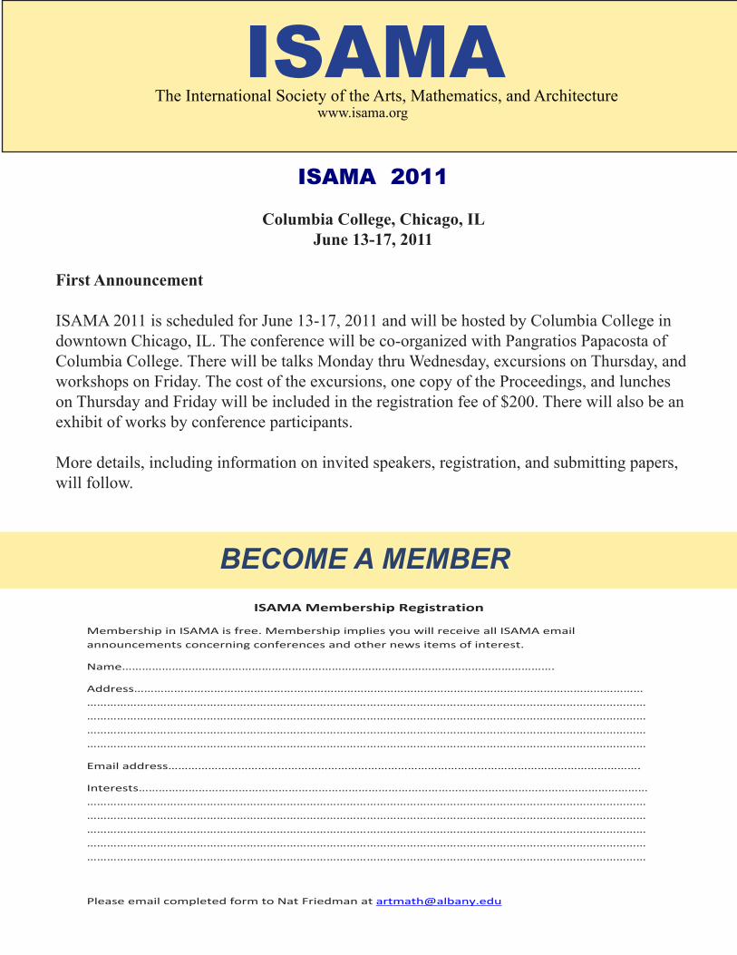
ISAMAwww.isama.org
BECOME A MEMBER
The International Society of the Arts, Mathematics, and Architecture
ISAMA 2011
Columbia College, Chicago, ILJune 13-17, 2011
First Announcement
ISAMA 2011 is scheduled for June 13-17, 2011 and will be hosted by Columbia College in downtown Chicago, IL. The conference will be co-organized with Pangratios Papacosta of Columbia College. There will be talks Monday thru Wednesday, excursions on Thursday, and workshops on Friday. The cost of the excursions, one copy of the Proceedings, and lunches on Thursday and Friday will be included in the registration fee of $200. There will also be an exhibit of works by conference participants.
More details, including information on invited speakers, registration, and submitting papers, will follow.
ISAMA Membership Registration
Membership in ISAMA is free. Membership implies you will receive all ISAMA email announcements concerning conferences and other news items of interest.
Name………………………………………………………………………………………………………………….
Address……………………………………………………………………………………………………………………………………………………………………………………………………………………………………………………………………………………………………………………………………………………………………………………………………………………………………………………………………………………………………………………………………………………………………………………………………………………………………………………………………………………………………………………………………………………………
Email address…………………………………………………………………………………………………………………………….
Interests…………………………………………………………………………………………………………………………………………………………………………………………………………………………………………………………………………………………………………………………………………………………………………………………………………………………………………………………………………………………………………………………………………………………………………………………………………………………………………………………………………………………………………………………………………………………………………………………………………………………………………………………………………………………………………………
Please email completed form to Nat Friedman at [email protected]
BECOME A MEMBER