hyosung comet 650 s r manual de reparatie www.manualedereparatie
TRANSCRIPT
SE
RV
ICE
MA
NU
AL
99000-94910
SERVICE MANUAL
HYOSUNG MOTORS & MACHINERY INC.
*Comet650S/R(SM)-COV 2005.4.28 5:11 PM 페이지1 001 PagePro 9100 300DPI 100LPI
SERVICING INFORMATION
GROUP INDEX
GENERAL INFORMATION 1
PERIODIC MAINTENANCE 2
ELECTRICAL SYSTEM 6
CHASSIS 7
8
This manual has been prepared on the basisof the latest specification at the time ofpublication.If modification has been made since then,difference may exist between the content ofthis manual and the actual vehicle.Illustrations in this manual are used to showthe basic principles of operation and workprocedures. They may not represent the actual vehicleexactly in detail.
COPYRIGHT HYOSUNG MOTORS & MACHINERY INC. 2005.
HYOSUNG MOTORS & MACHINERY INC.
FOREWORD
This manual contains an introductory description onHYOSUNG & andprocedures for its inspection/service and overhaul of its main components.It covers the differences from and pleaserefer to the service manual of (99000-94810)for others which are not covered in this manual.This page numbers on the top are ones which are in theservice manual of and ones on the bottomare the page numbers in this manual.Other information considered as generally known is notincluded.Read GENERAL INFORMATION section to familiarizeyourself with outline of the vehicle and MAINTENANCEand other sections to use as a guide for properinspection and service.This manual will help you know the vehicle better so thatyou can assure your customers of your optimum anquick service.
WARNINGThis manual is intended for those who haveenough knowledge and skills for servicingHYOSUNG vehicles. Without such knowledge andskills, you should not attempt servicing by relyingon this manual only.Instead, please contact your nearby authorizedHYOSUNG motorcycle dealer.
2
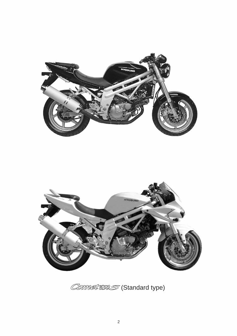
(Standard type)
3
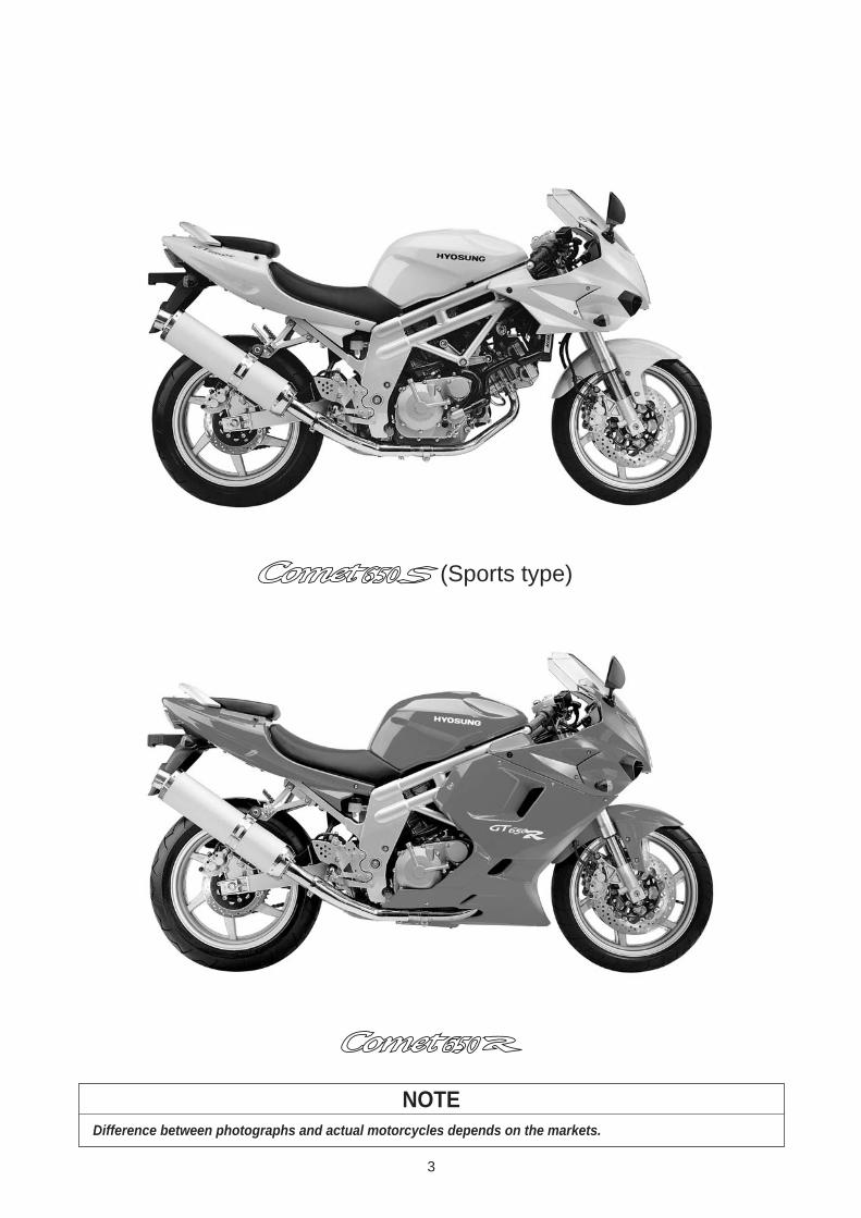
NOTEDifference between photographs and actual motorcycles depends on the markets.
(Sports type)
4
HOW TO USE THIS MANUALTO LOCATE WHAT YOU ARELOOKING FOR:1. The text of this manual is divided into sections.2. As the title of these sections are listed on the previous
page as GROUP INDEX, select the section where you are look-ing for.
3. Holding the manual as shown at the right will allow you to find the first page of the section easily.
4. On the first page of each section, its contents are listed. Findthe item and page you need.
SYMBOLListed in the table below are the symbols indicating instructions and other information necessary for servicing and meaning associated with them respectively.
Apply THREAD LOCK 1324
Apply or use brake fluid.
Measure in voltage range.
Measure in resistance range.
Measure in current range.
Use special tool.
Use engine coolant.
Torque control required.Data beside it indicates specified torque.
Apply oil. Use engine oil unless otherwisespecified.
Apply SUPER GREASE A
Apply SILICONE GREASE.
Apply MOLY PASTE.
Apply BOND 1215 .
Use fork oil.
DEFINITIONSYMBOL DEFINITIONSYMBOL
Apply SUPER GREASE C .
5
GENERAL INFORMATION
EXTERIOR ILLUSTRATION 6 (1-7-1)
SPECIFICATIONS 9 (1-8)
CONTENTS 1
1-7-1 GENERAL INFORMATION
6
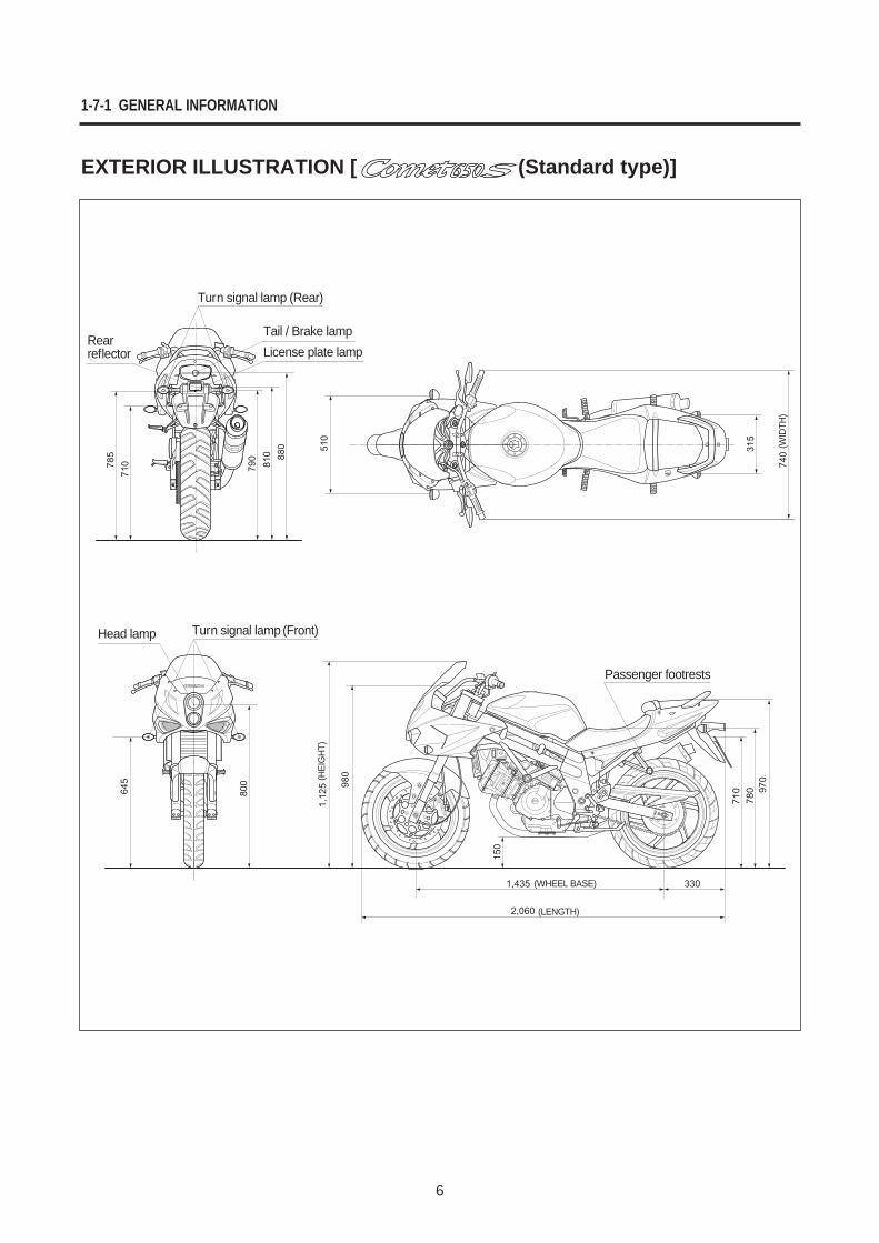
EXTERIOR ILLUSTRATION [ (Standard type)]
Rearreflector
Turn signal lamp (Rear)
Tail / Brake lampLicense plate lamp
Head lamp Turn signal lamp (Front)
Passenger footrests
(HEI
GHT
)
(WID
TH)
(WHEEL BASE)
(LENGTH)
GENERAL INFORMATION 1-7-2
7
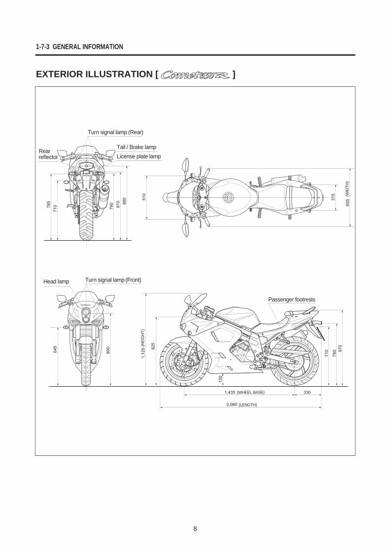
510
315
655
1,12
5 825
150
1,435
2,060
330
780
710 97
0
645 80
0
785
710 790
810 88
0
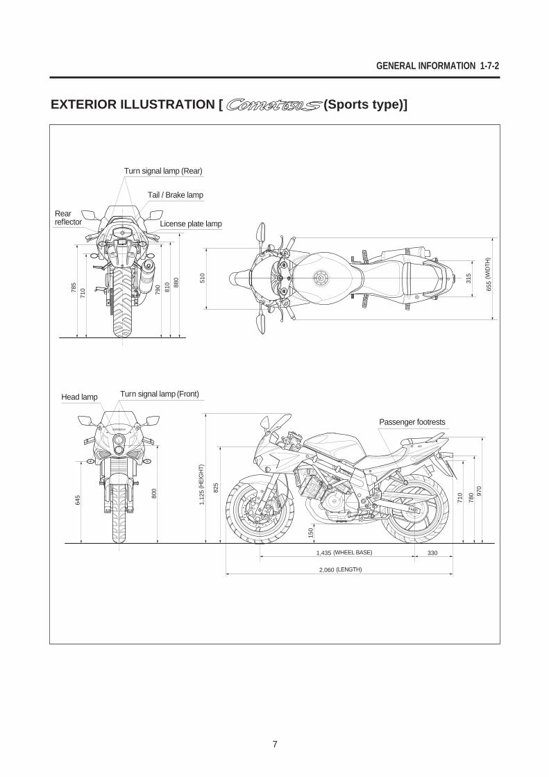
EXTERIOR ILLUSTRATION [ (Sports type)]
Rearreflector
Turn signal lamp (Rear)
Tail / Brake lamp
License plate lamp
Head lamp Turn signal lamp (Front)
Passenger footrests
(HEI
GHT
)
(WID
TH)
(WHEEL BASE)
(LENGTH)
1-7-3 GENERAL INFORMATION
8
EXTERIOR ILLUSTRATION [ ]
Rearreflector
Turn signal lamp (Rear)
Tail / Brake lampLicense plate lamp
Head lamp Turn signal lamp (Front)
Passenger footrests
(HEI
GHT
)
(WID
TH)
(WHEEL BASE)
(LENGTH)
GENERAL INFORMATION 1-8
9
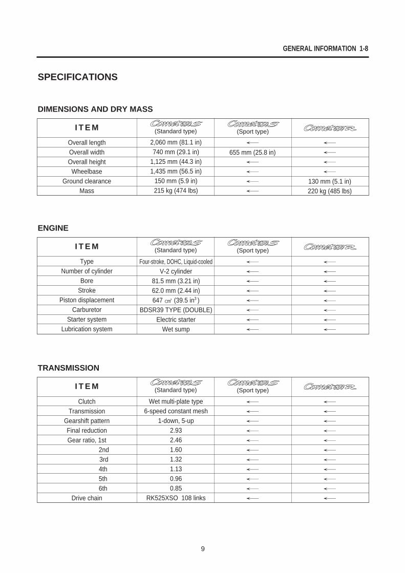
2,060 mm (81.1 in)740 mm (29.1 in)
1,125 mm (44.3 in)1,435 mm (56.5 in)
150 mm (5.9 in)215 kg (474 lbs)
655 mm (25.8 in)
130 mm (5.1 in)220 kg (485 lbs)
Overall lengthOverall widthOverall height
WheelbaseGround clearance
Mass
I T E M
SPECIFICATIONS
DIMENSIONS AND DRY MASS
(Standard type) (Sport type)
Four-stroke, DOHC, Liquid-cooledV-2 cylinder
81.5 mm (3.21 in)62.0 mm (2.44 in)647 (39.5 in3 )
BDSR39 TYPE (DOUBLE)Electric starter
Wet sump
TypeNumber of cylinder
BoreStroke
Piston displacementCarburetor
Starter systemLubrication system
I T E M
ENGINE
(Standard type) (Sport type)
Wet multi-plate type6-speed constant mesh
1-down, 5-up 2.932.461.601.321.130.960.85
RK525XSO 108 links
ClutchTransmission
Gearshift patternFinal reductionGear ratio, 1st
2nd3rd4th5th6th
Drive chain
I T E M
TRANSMISSION
(Standard type) (Sport type)
1-9 GENERAL INFORMATION
10
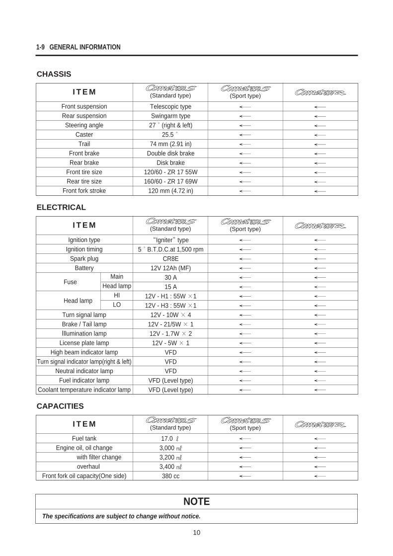
NOTEThe specifications are subject to change without notice.
Telescopic typeSwingarm type
27 (right & left)25.5
74 mm (2.91 in)Double disk brake
Disk brake120/60 - ZR 17 55W160/60 - ZR 17 69W
120 mm (4.72 in)
Front suspensionRear suspensionSteering angle
CasterTrail
Front brakeRear brake
Front tire size Rear tire size
Front fork stroke
I T E M
CHASSIS
(Standard type) (Sport type)
Igniter type5 B.T.D.C.at 1,500 rpm
CR8E12V 12Ah (MF)
30 A15 A
12V - H1 : 55W 112V - H3 : 55W 1
12V - 10W 412V - 21/5W 112V - 1.7W 212V - 5W 1
VFDVFDVFD
VFD (Level type)VFD (Level type)
Ignition typeIgnition timing
Spark plugBattery
Fuse
Head lamp
Turn signal lampBrake / Tail lampIllumination lamp
License plate lampHigh beam indicator lamp
Turn signal indicator lamp(right & left)Neutral indicator lamp
Fuel indicator lampCoolant temperature indicator lamp
I T E M
ELECTRICAL
(Standard type) (Sport type)
MainHead lamp
HILO
17.0 3,000 3,200 3,400 380 cc
Fuel tankEngine oil, oil change
with filter changeoverhaul
Front fork oil capacity(One side)
I T E M
CAPACITIES
(Standard type) (Sport type)
11
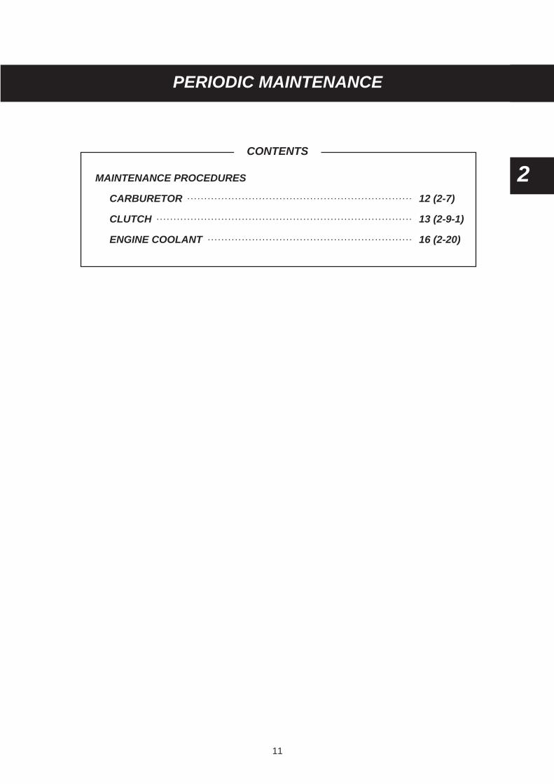
MAINTENANCE PROCEDURES
CARBURETOR 12 (2-7)
CLUTCH 13 (2-9-1)
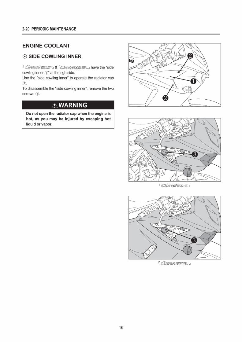
ENGINE COOLANT 16 (2-20)
CONTENTS
2
2 PERIODIC MAINTENANCE
2-7 PERIODIC MAINTENANCE
12
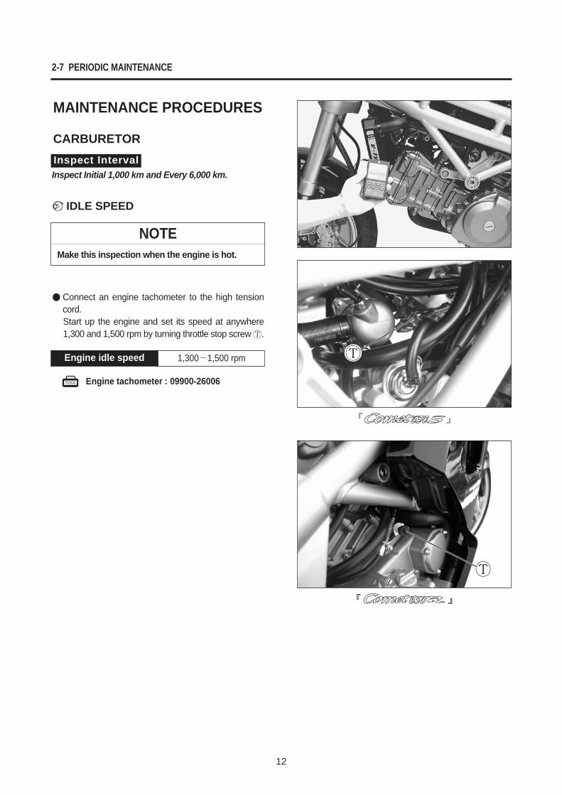
Connect an engine tachometer to the high tensioncord.Start up the engine and set its speed at anywhere1,300 and 1,500 rpm by turning throttle stop screw .
1,300 1,500 rpmEngine idle speed
Engine tachometer : 09900-26006
MAINTENANCE PROCEDURES
CARBURETOR
¢`IDLE SPEED
Inspect IntervalInspect Initial 1,000 km and Every 6,000 km.
NOTEMake this inspection when the engine is hot.
PERIODIC MAINTENANCE 2-9-1
13
(Standard type)
(Sports type)
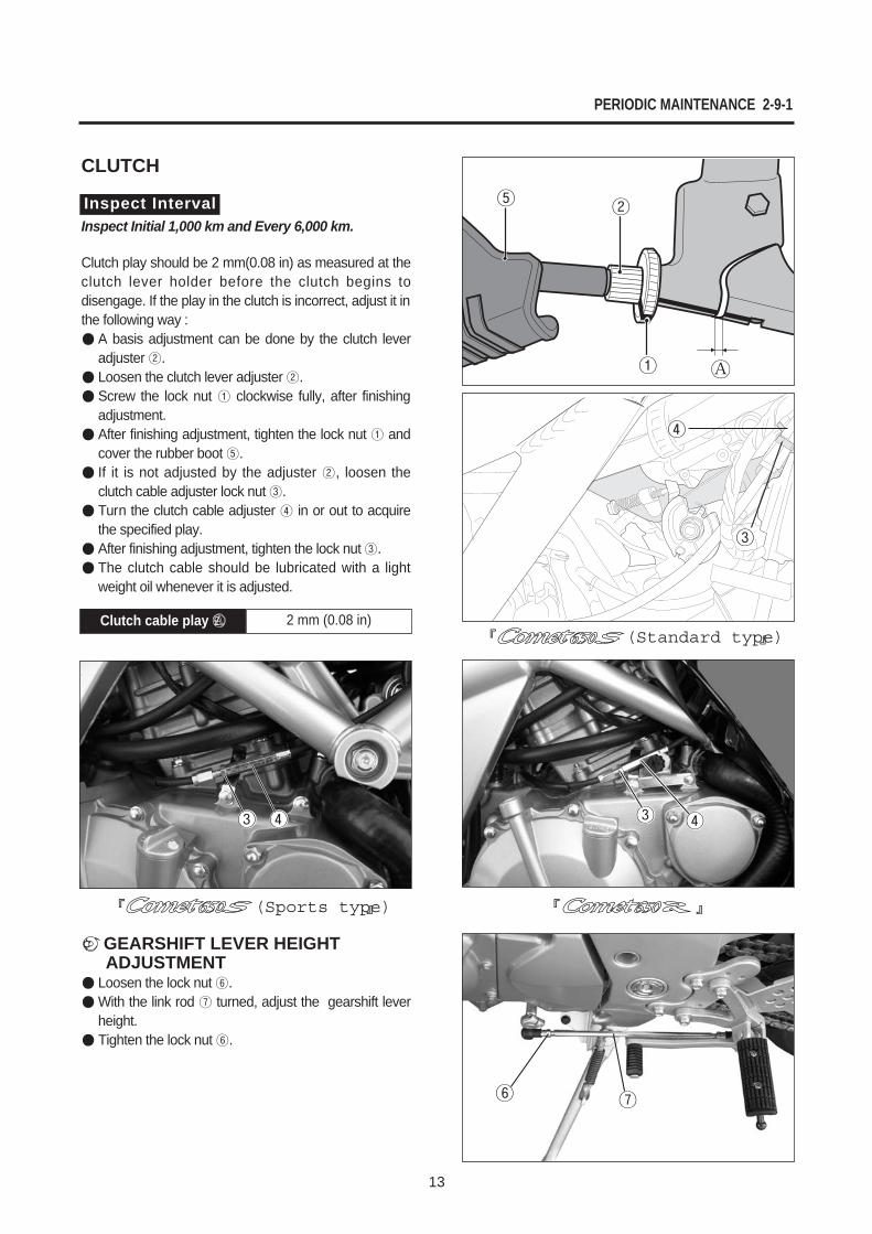
CLUTCH
Clutch play should be 2 mm(0.08 in) as measured at theclutch lever holder before the clutch begins todisengage. If the play in the clutch is incorrect, adjust it inthe following way :
A basis adjustment can be done by the clutch leveradjuster .Loosen the clutch lever adjuster .Screw the lock nut clockwise fully, after finishingadjustment.After finishing adjustment, tighten the lock nut andcover the rubber boot .If it is not adjusted by the adjuster , loosen theclutch cable adjuster lock nut .Turn the clutch cable adjuster in or out to acquirethe specified play.After finishing adjustment, tighten the lock nut .The clutch cable should be lubricated with a lightweight oil whenever it is adjusted.
¢`GEARSHIFT LEVER HEIGHTADJUSTMENT
Loosen the lock nut .With the link rod turned, adjust the gearshift leverheight.Tighten the lock nut .
2 mm (0.08 in)Clutch cable play £
Inspect IntervalInspect Initial 1,000 km and Every 6,000 km.
14
2-9-2 PERIODIC MAINTENANCE
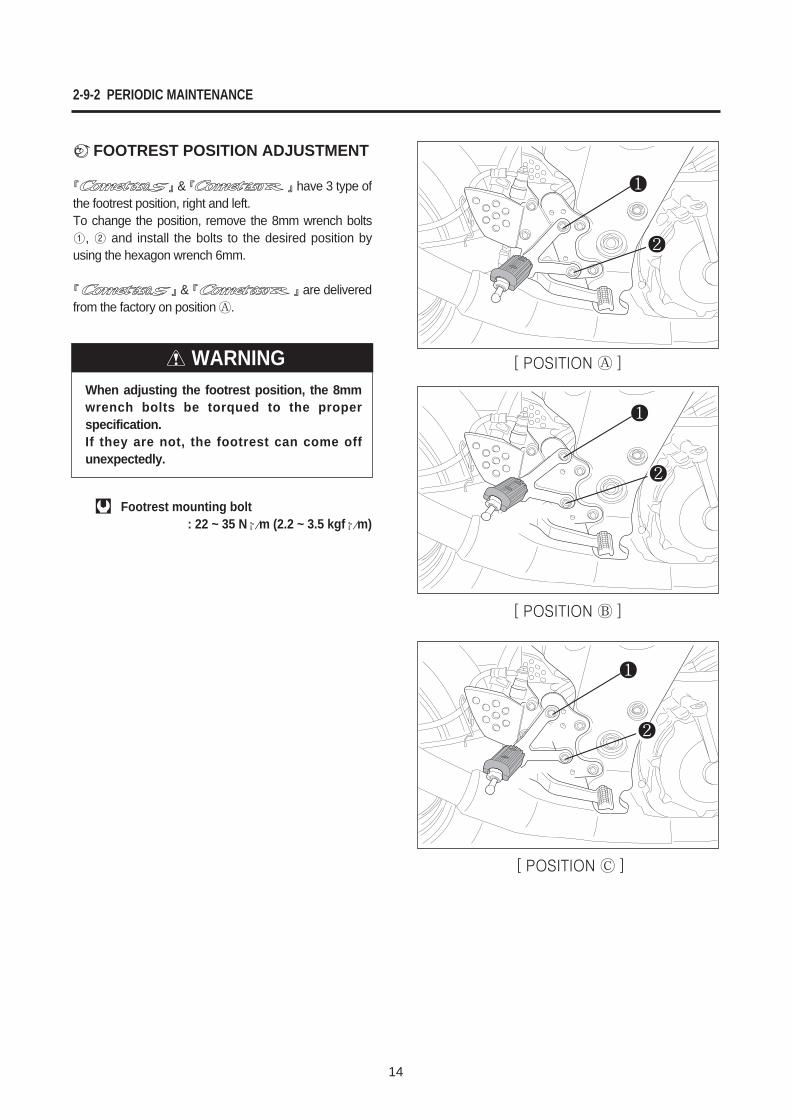
¢`FOOTREST POSITION ADJUSTMENT
& have 3 type ofthe footrest position, right and left.To change the position, remove the 8mm wrench bolts
, and install the bolts to the desired position byusing the hexagon wrench 6mm.
& are deliveredfrom the factory on position .
WARNINGWhen adjusting the footrest position, the 8mmwrench bolts be torqued to the properspecification.If they are not, the footrest can come offunexpectedly.
Footrest mounting bolt: 22 ~ 35 N¡⁄m (2.2 ~ 3.5 kgf¡⁄m)
15
PERIODIC MAINTENANCE 2-9-3
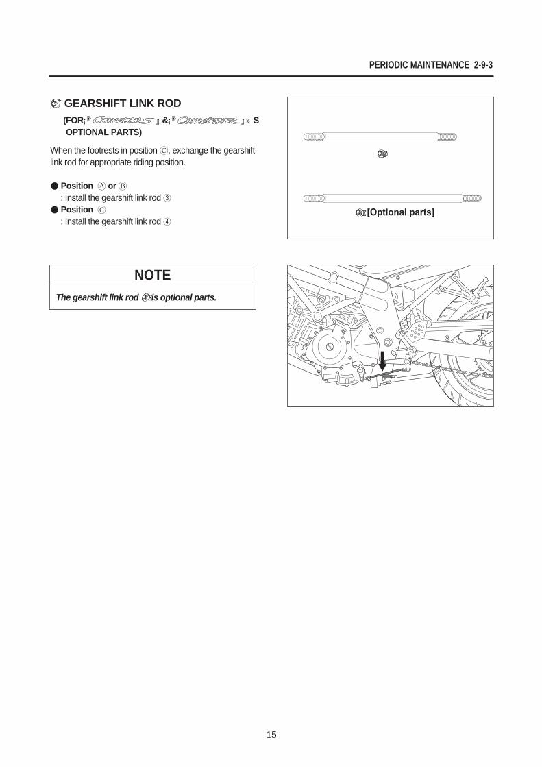
¢`GEARSHIFT LINK ROD(FOR ¡” ¡»& ¡” ¡»�SOPTIONAL PARTS)
When the footrests in position , exchange the gearshiftlink rod for appropriate riding position.
Position or : Install the gearshift link rod Position: Install the gearshift link rod
¤Ø
¤Œ
NOTEThe gearshift link rod ¤Œis optional parts.
17
IGNITION SYSTEM 18 (6-6)
LAMP 19 (6-16-1)
ELECTRICAL SYSTEM
6
CONTENTS
6-6 ELECTRICAL SYSTEM
18
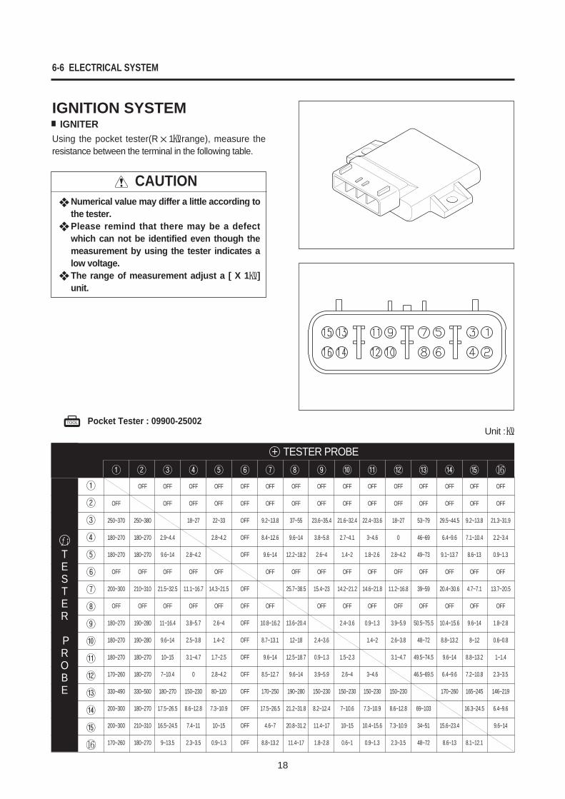
CAUTIONNumerical value may differ a little according tothe tester.Please remind that there may be a defectwhich can not be identified even though themeasurement by using the tester indicates alow voltage.The range of measurement adjust a [ X 1 ]unit.
IGNITION SYSTEMIGNITER
Using the pocket tester(R 1 range), measure theresistance between the terminal in the following table.
Unit : Pocket Tester : 09900-25002
+ TESTER PROBE
OFF OFF OFF OFF OFF OFF OFF OFF OFF OFF OFF OFF OFF OFF OFF
OFF OFF OFF OFF OFF OFF OFF OFF OFF OFF OFF OFF OFF OFF OFF
250~370 250~380 18~27 22~33 OFF 9.2~13.8 37~55 23.6~35.4 21.6~32.4 22.4~33.6 18~27 53~79 29.5~44.5 9.2~13.8 21.3~31.9
180~270 180~270 2.9~4.4 2.8~4.2 OFF 8.4~12.6 9.6~14 3.8~5.8 2.7~4.1 3~4.6 0 46~69 6.4~9.6 7.1~10.4 2.2~3.4
180~270 180~270 9.6~14 2.8~4.2 OFF 9.6~14 12.2~18.2 2.6~4 1.4~2 1.8~2.6 2.8~4.2 49~73 9.1~13.7 8.6~13 0.9~1.3
OFF OFF OFF OFF OFF OFF OFF OFF OFF OFF OFF OFF OFF OFF OFF
200~300 210~310 21.5~32.5 11.1~16.7 14.3~21.5 OFF 25.7~38.5 15.4~23 14.2~21.2 14.6~21.8 11.2~16.8 39~59 20.4~30.6 4.7~7.1 13.7~20.5
OFF OFF OFF OFF OFF OFF OFF OFF OFF OFF OFF OFF OFF OFF OFF
180~270 190~280 11~16.4 3.8~5.7 2.6~4 OFF 10.8~16.2 13.6~20.4 2.4~3.6 0.9~1.3 3.9~5.9 50.5~75.5 10.4~15.6 9.6~14 1.8~2.8
180~270 190~280 9.6~14 2.5~3.8 1.4~2 OFF 8.7~13.1 12~18 2.4~3.6 1.4~2 2.6~3.8 48~72 8.8~13.2 8~12 0.6~0.8
180~270 180~270 10~15 3.1~4.7 1.7~2.5 OFF 9.6~14 12.5~18.7 0.9~1.3 1.5~2.3 3.1~4.7 49.5~74.5 9.6~14 8.8~13.2 1~1.4
170~260 180~270 7~10.4 0 2.8~4.2 OFF 8.5~12.7 9.6~14 3.9~5.9 2.6~4 3~4.6 46.5~69.5 6.4~9.6 7.2~10.8 2.3~3.5
330~490 330~500 180~270 150~230 80~120 OFF 170~250 190~280 150~230 150~230 150~230 150~230 170~260 165~245 146~219
200~300 180~270 17.5~26.5 8.6~12.8 7.3~10.9 OFF 17.5~26.5 21.2~31.8 8.2~12.4 7~10.6 7.3~10.9 8.6~12.8 69~103 16.3~24.5 6.4~9.6
200~300 210~310 16.5~24.5 7.4~11 10~15 OFF 4.6~7 20.8~31.2 11.4~17 10~15 10.4~15.6 7.3~10.9 34~51 15.6~23.4 9.6~14
170~260 180~270 9~13.5 2.3~3.5 0.9~1.3 OFF 8.8~13.2 11.4~17 1.8~2.8 0.6~1 0.9~1.3 2.3~3.5 48~72 8.6~13 8.1~12.1
ƒ¡TESTER
PROBE
ELECTRICAL SYSTEM 6-16-1
19
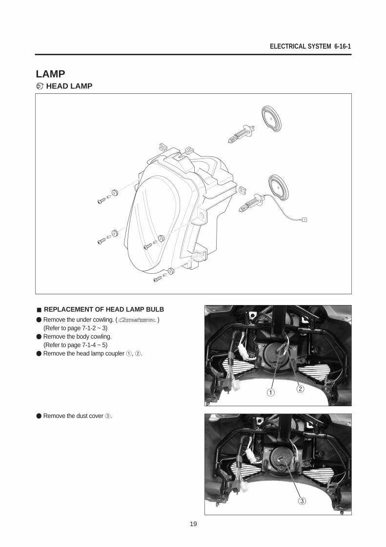
REPLACEMENT OF HEAD LAMP BULBRemove the under cowling. ( )(Refer to page 7-1-2 ~ 3)Remove the body cowling.(Refer to page 7-1-4 ~ 5)Remove the head lamp coupler , .
Remove the dust cover .
LAMP¢`HEAD LAMP
6-16-2 ELECTRICAL SYSTEM
20
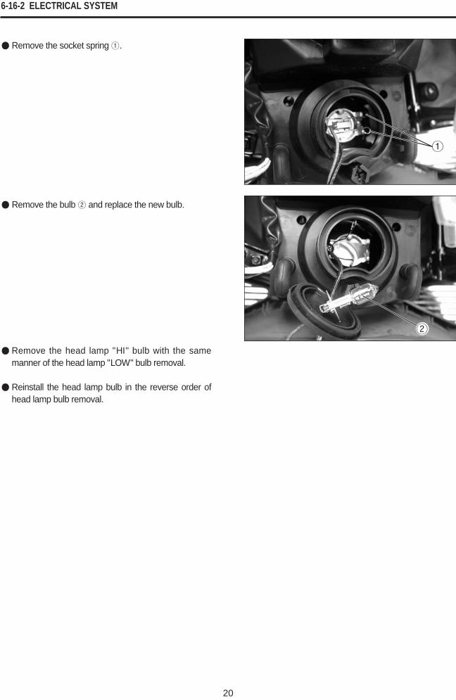
Remove the socket spring .
Remove the bulb and replace the new bulb.
Remove the head lamp "H I" bulb with the samemanner of the head lamp "LOW" bulb removal.
Reinstall the head lamp bulb in the reverse order ofhead lamp bulb removal.
ELECTRICAL SYSTEM 6-17-1
21
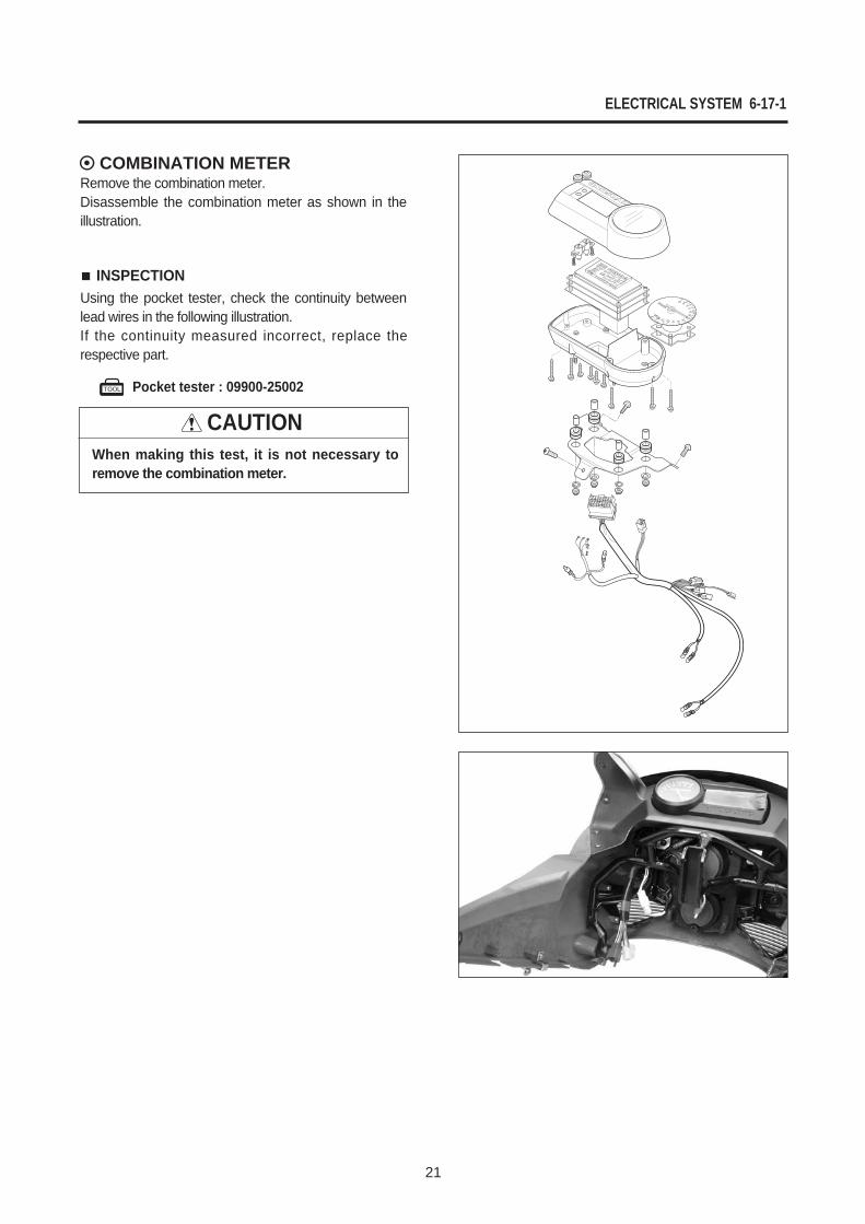
COMBINATION METERRemove the combination meter. Disassemble the combination meter as shown in theillustration.
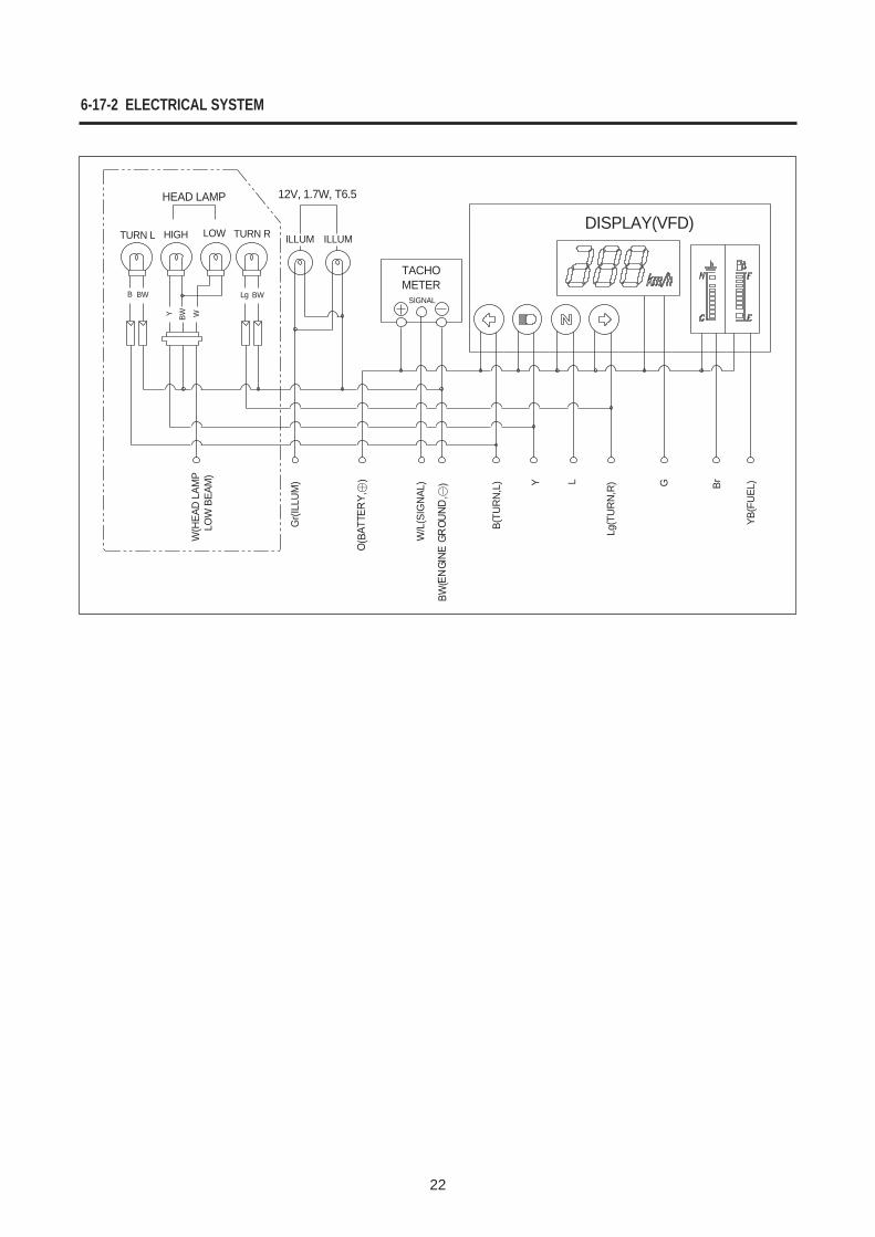
INSPECTIONUsing the pocket tester, check the continuity betweenlead wires in the following illustration.If the continuity measured incorrect, replace therespective part.
Pocket tester : 09900-25002
CAUTIONWhen making this test, it is not necessary toremove the combination meter.
22
HEAD LAMP 12V, 1.7W, T6.5
TACHOMETER
DISPLAY(VFD)TURN L
B BW Lg BW
BW WY
HIGH LOW TURN R ILLUM ILLUM
SIGNAL
YB(F
UEL
)
Lg(T
UR
N,R
) BrG
B(TU
RN
,L)
W/L
(SIG
NAL
)
Gr(I
LLU
M)
W(H
EAD
LAM
P
LO
W B
EAM
) LY
6-17-2 ELECTRICAL SYSTEM
23
CHASSIS
EXTERIOR PARTS 24 (7-1-1)
HANDLEBARS 29 (7-13-1)
STEERING 33 (7-23)
CONTENTS
7
7-1-1 CHASSIS
24
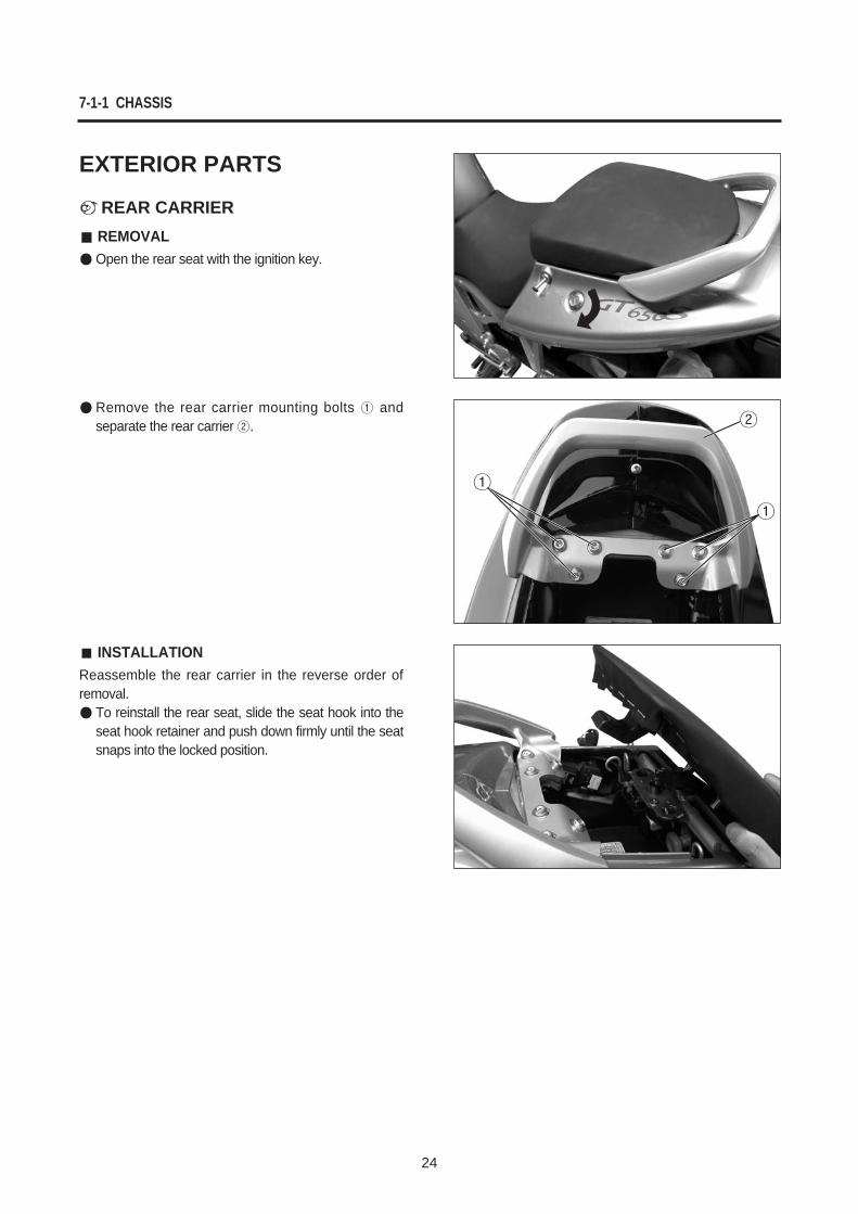
EXTERIOR PARTS
¢`REAR CARRIERREMOVALOpen the rear seat with the ignition key.
Remove the rear carrier mounting bolts andseparate the rear carrier .
INSTALLATIONReassemble the rear carrier in the reverse order ofremoval.
To reinstall the rear seat, slide the seat hook into theseat hook retainer and push down firmly until the seatsnaps into the locked position.
CHASSIS 7-1-2
25
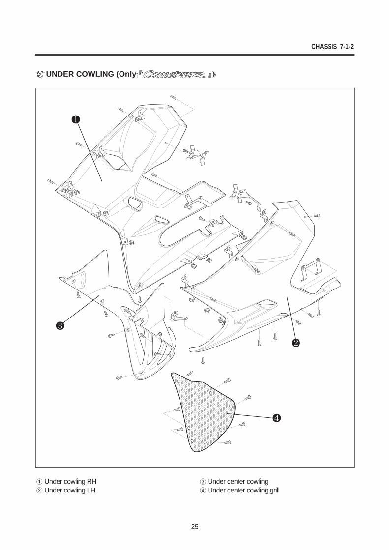
¢`UNDER COWLING (Only ¡” ¡»))
Under cowling RHUnder cowling LH
Under center cowlingUnder center cowling grill
7-1-3 CHASSIS
26
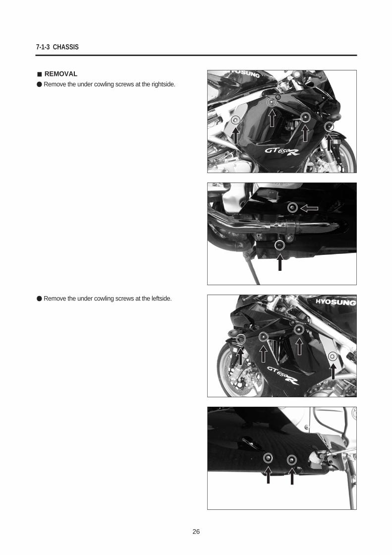
REMOVALRemove the under cowling screws at the rightside.
Remove the under cowling screws at the leftside.
CHASSIS 7-1-4
27
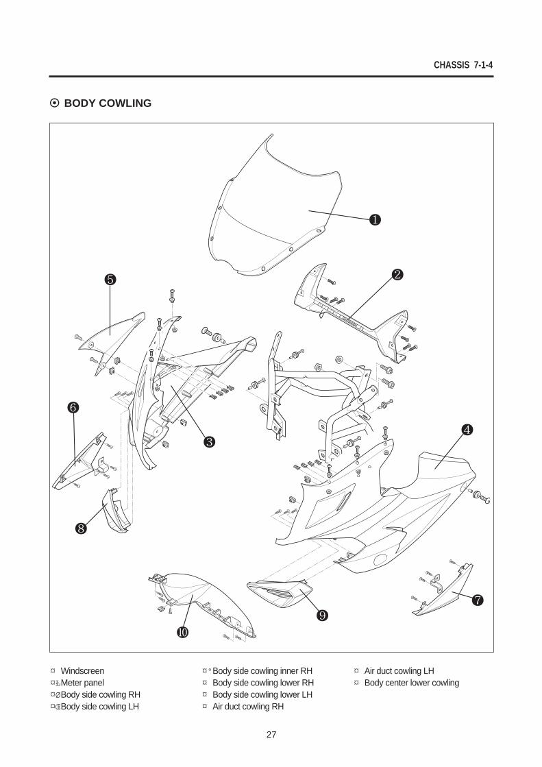
BODY COWLING
¤ Windscreen¤ŁMeter panel¤ØBody side cowling RH¤ŒBody side cowling LH
¤ºBody side cowling inner RH¤ Body side cowling lower RH¤ Body side cowling lower LH¤ Air duct cowling RH
¤ Air duct cowling LH¤ Body center lower cowling
7-1-5 CHASSIS
28
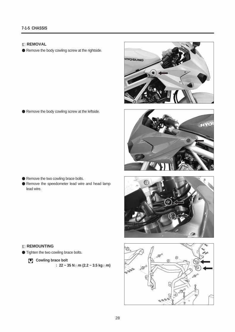
§ REMOVALRemove the body cowling screw at the rightside.
Remove the body cowling screw at the leftside.
Remove the two cowling brace bolts.Remove the speedometer lead wire and head lamplead wire.
§ REMOUNTINGTighten the two cowling brace bolts.
Cowling brace bolt : 22 ~ 35 N¡⁄m (2.2 ~ 3.5 kg¡⁄m)
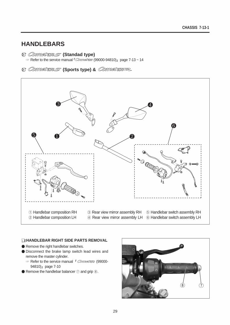
HANDLEBARS¢` (Standad type)
Refer to the service manual (99000-94810) page 7-13 ~ 14
¢` (Sports type) &
CHASSIS 7-13-1
29
¡ÆHANDLEBAR RIGHT SIDE PARTS REMOVALRemove the right handlebar switches.Disconnect the brake lamp switch lead wires andremove the master cylinder.
Refer to the service manual (99000-94810) page 7-10
Remove the handlebar balancer and grip .
Handlebar composition RHHandlebar composition LH
Rear view mirror assembly RHRear view mirror assembly LH
Handlebar switch assembly RHHandlebar switch assembly LH
7-13-2 CHASSIS
30
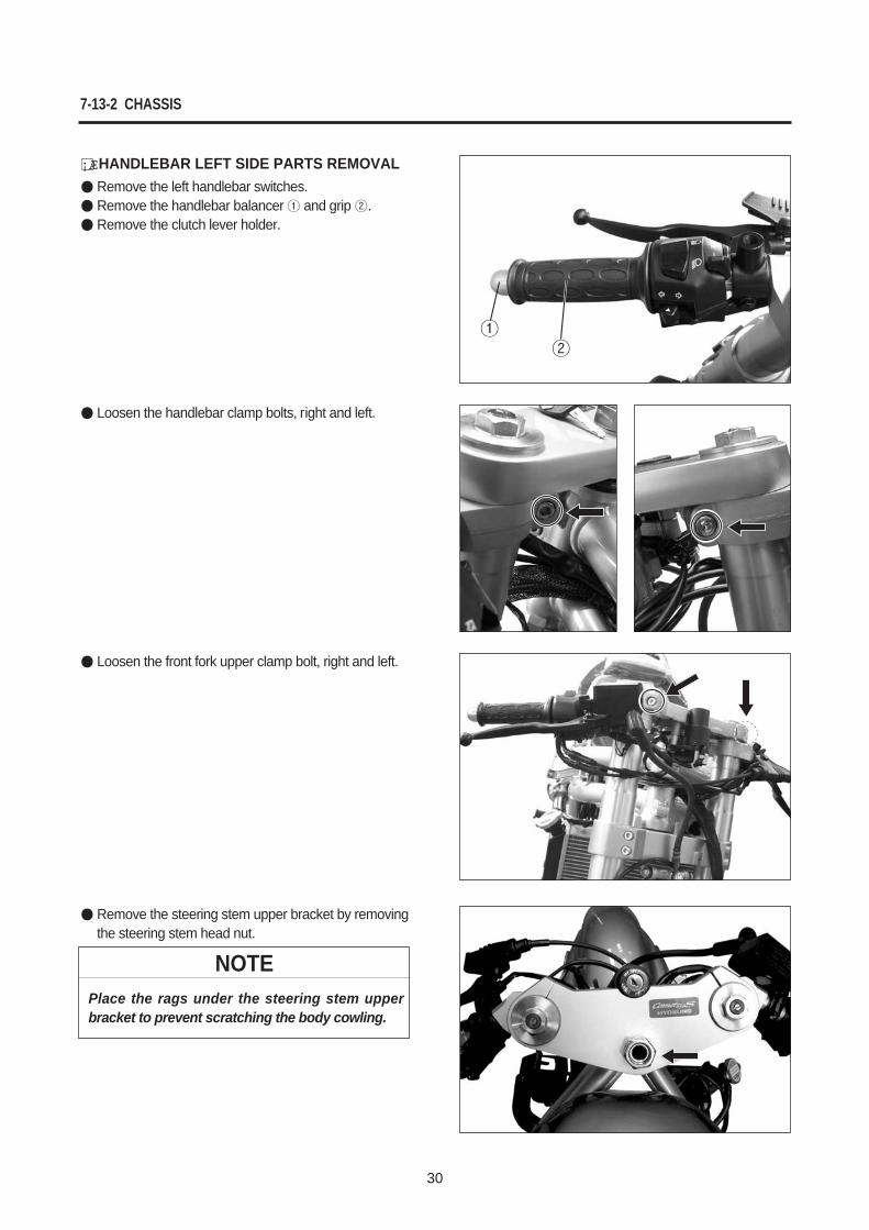
¡ÆHANDLEBAR LEFT SIDE PARTS REMOVALRemove the left handlebar switches.Remove the handlebar balancer and grip .Remove the clutch lever holder.
Loosen the handlebar clamp bolts, right and left.
Remove the steering stem upper bracket by removingthe steering stem head nut.
Loosen the front fork upper clamp bolt, right and left.
NOTEPlace the rags under the steering stem upperbracket to prevent scratching the body cowling.
CHASSIS 7-14-1
31
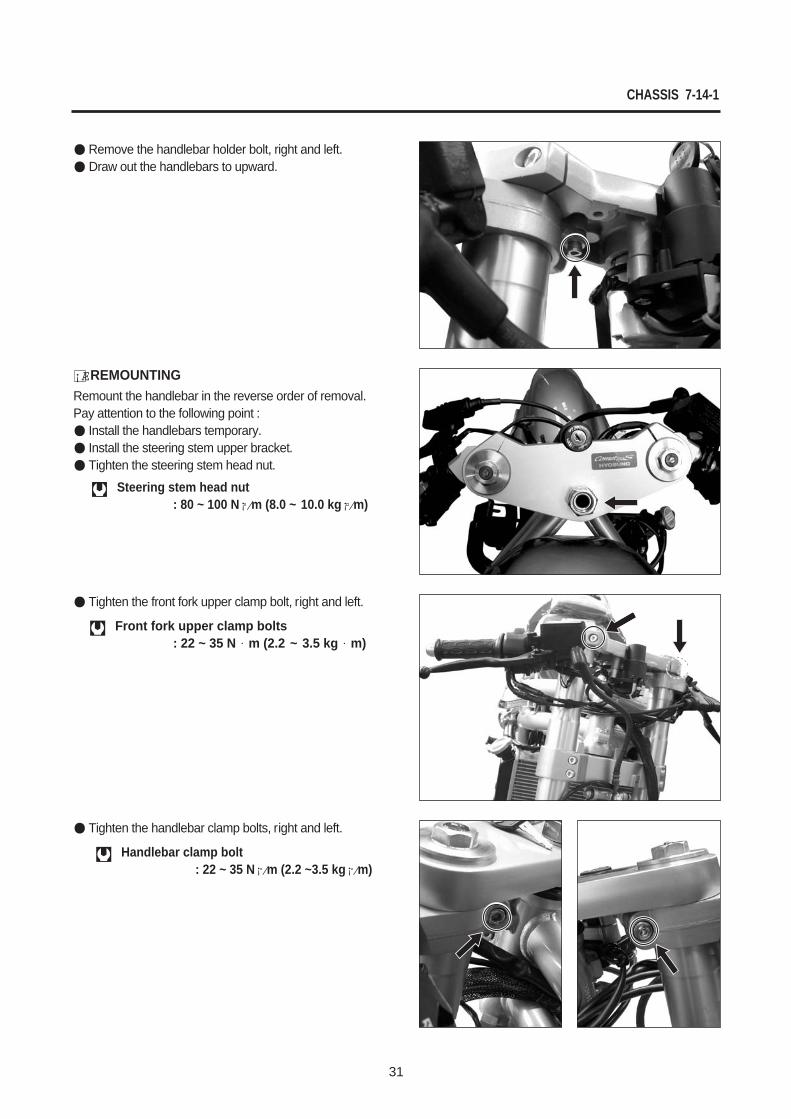
Remove the handlebar holder bolt, right and left.Draw out the handlebars to upward.
Tighten the front fork upper clamp bolt, right and left.
Tighten the handlebar clamp bolts, right and left.
¡ÆREMOUNTINGRemount the handlebar in the reverse order of removal.Pay attention to the following point :
Install the handlebars temporary.Install the steering stem upper bracket.Tighten the steering stem head nut.
Steering stem head nut: 80 ~ 100 N¡⁄m (8.0 ~ 10.0 kg¡⁄m)
Front fork upper clamp bolts: 22 ~ 35 N m (2.2 ~ 3.5 kg m)
Handlebar clamp bolt: 22 ~ 35 N¡⁄m (2.2 ~3.5 kg¡⁄m)
7-14-2 CHASSIS
32
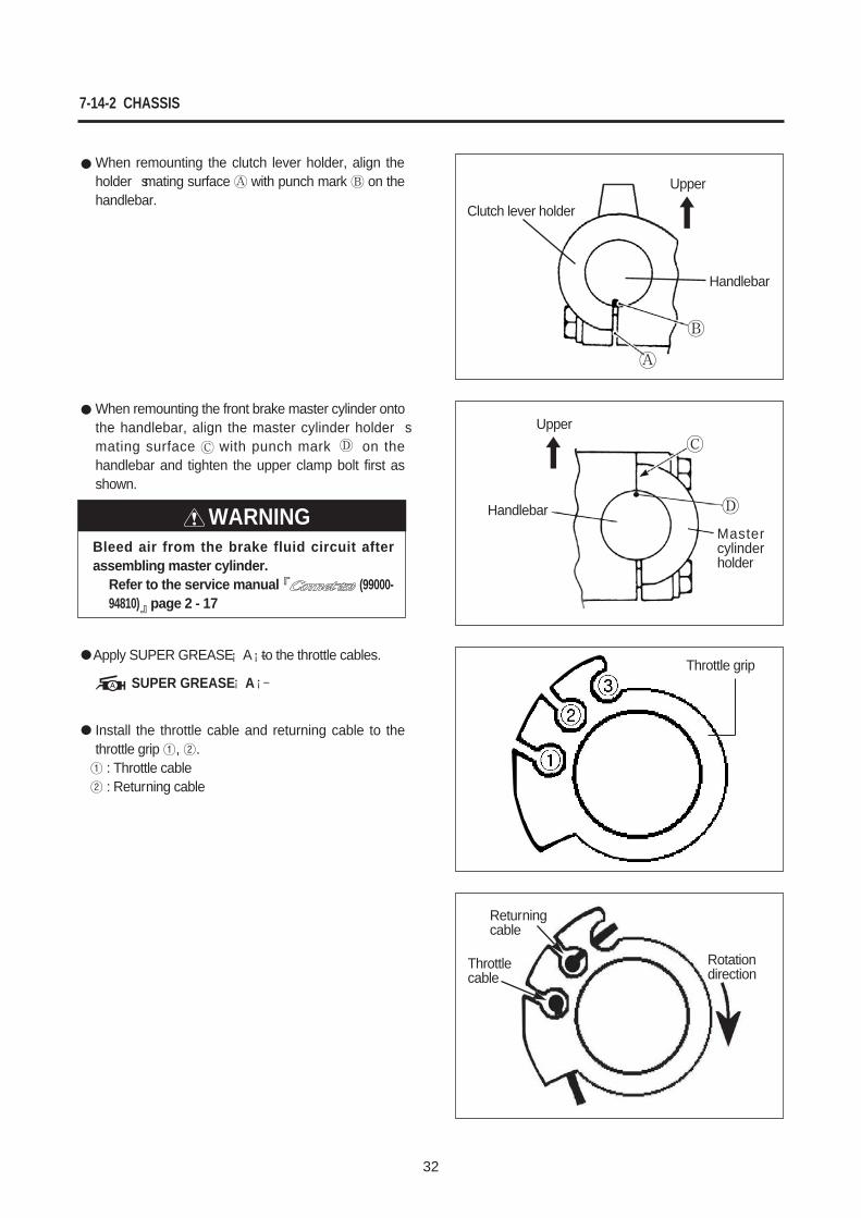
Apply SUPER GREASE ¡ A¡–to the throttle cables.
Install the throttle cable and returning cable to thethrottle grip , .
: Throttle cable: Returning cable
SUPER GREASE ¡ A¡–Throttle grip
Rotation direction
Throttle cable
Handlebar
Handlebar
Mastercylinderholder
When remounting the clutch lever holder, align theholder�s mating surface with punch mark on thehandlebar.
When remounting the front brake master cylinder ontothe handlebar, align the master cylinder holder�smating surface with punch mark on thehandlebar and tighten the upper clamp bolt first asshown.
Returningcable
Upper
Upper
WARNINGBleed air from the brake fluid circuit afterassembling master cylinder.
Refer to the service manual (99000-94810) page 2 - 17
Clutch lever holder
CHASSIS 7-23
33
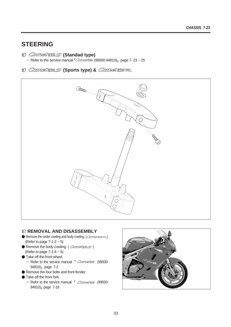
¢`REMOVAL AND DISASSEMBLYRemove the under cowling and body cowling. ( )(Refer to page 7-1-2 ~ 5)Remove the body cowling. ( )(Refer to page 7-1-4 ~ 5)Take off the front wheel.
Refer to the service manual (99000-94810) page 7-2
Remove the four bolts and front fender. Take off the front fork.
Refer to the service manual (99000-94810) page 7-16
STEERING¢` (Standad type)
Refer to the service manual (99000-94810) page 7- 23 ~ 25
¢` (Sports type) &
7-24 CHASSIS
34
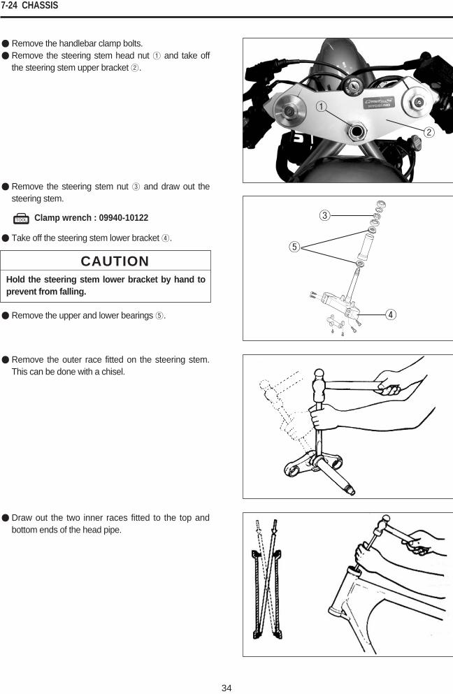
Remove the handlebar clamp bolts.Remove the steering stem head nut and take offthe steering stem upper bracket .
Clamp wrench : 09940-10122
Remove the steering stem nut and draw out thesteering stem.
Take off the steering stem lower bracket .
Remove the upper and lower bearings .
CAUTIONHold the steering stem lower bracket by hand toprevent from falling.
Remove the outer race fitted on the steering stem.This can be done with a chisel.
Draw out the two inner races fitted to the top andbottom ends of the head pipe.
CHASSIS 7-25-1
35
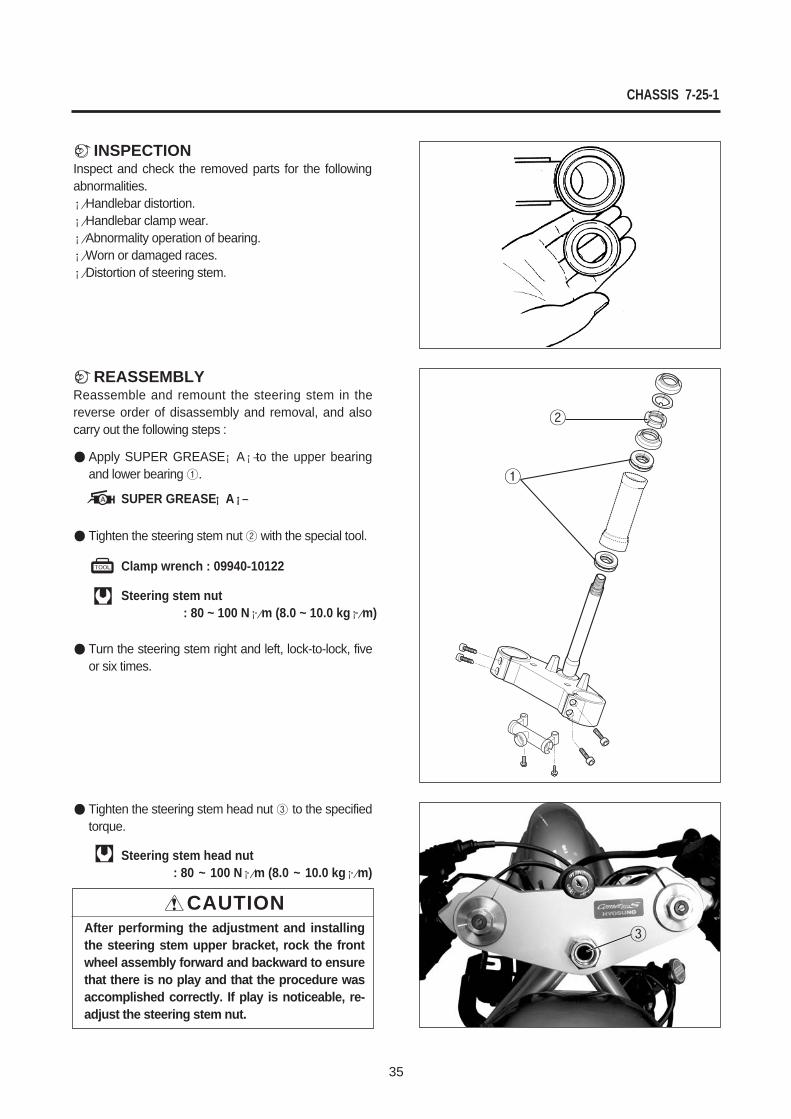
Tighten the steering stem nut with the special tool.
Turn the steering stem right and left, lock-to-lock, fiveor six times.
Tighten the steering stem head nut to the specifiedtorque.
Clamp wrench : 09940-10122
Steering stem nut : 80 ~ 100 N¡⁄m (8.0 ~ 10.0 kg¡⁄m)
CAUTIONAfter performing the adjustment and installingthe steering stem upper bracket, rock the frontwheel assembly forward and backward to ensurethat there is no play and that the procedure wasaccomplished correctly. If play is noticeable, re-adjust the steering stem nut.
¢`INSPECTIONInspect and check the removed parts for the followingabnormalities.¡⁄Handlebar distortion.¡⁄Handlebar clamp wear.¡⁄Abnormality operation of bearing.¡⁄Worn or damaged races.¡⁄Distortion of steering stem.
¢`REASSEMBLYReassemble and remount the steering stem in thereverse order of disassembly and removal, and alsocarry out the following steps :
Apply SUPER GREASE ¡ A¡–to the upper bearingand lower bearing .
Steering stem head nut : 80 ~ 100 N¡⁄m (8.0 ~ 10.0 kg¡⁄m)
SUPER GREASE ¡¡ A¡–¡–
36
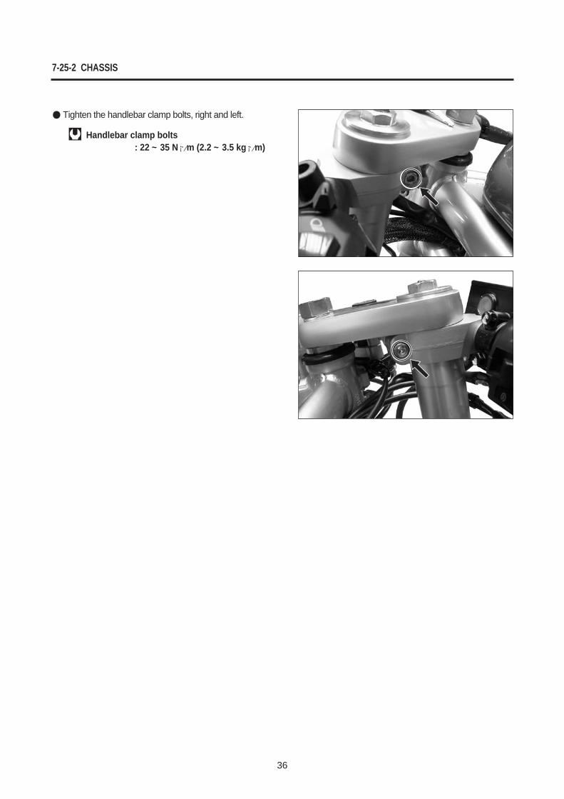
Tighten the handlebar clamp bolts, right and left.
Handlebar clamp bolts : 22 ~ 35 N¡⁄m (2.2 ~ 3.5 kg¡⁄m)
7-25-2 CHASSIS
37
SERVICING INFORMATION
SERVICE DATA 38(8-20)
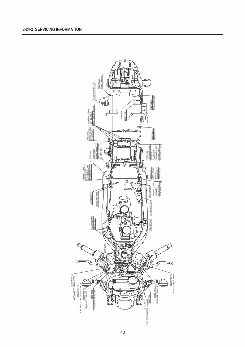
WIRE AND CABLE ROUTING 39(8-24-1)
WIRING DIAGRAM 47(8-28)
CONTENTS
8
8-20 SERVICING INFORMATION
38
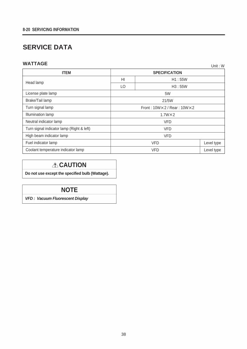
License plate lamp
Brake/Tail lamp
Turn signal lamp
Illumination lamp
Neutral indicator lamp
Turn signal indicator lamp (Right & left)
High beam indicator lamp
Fuel indicator lamp
Coolant temperature indicator lamp
5W
21/5W
Front : 10W 2 / Rear : 10W 2
1.7W 2
VFD
VFD
VFD
H1 : 55W
H3 : 55W
VFD
VFD
ITEM SPECIFICATIONHI
LO
Level type
Level type
WATTAGE Unit : W
CAUTIONDo not use except the specified bulb (Wattage).
NOTEVFD : Vacuum Fluorescent Display
Head lamp
SERVICE DATA
SERVICING INFORMATION 8-24-1
39
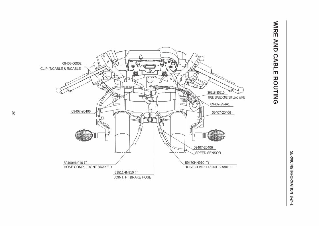
CLIP, T/CABLE & R/CABLE
09407-20406
09407-254A1
36618-30610TUBE, SPEEDOMETER LEAD WIRE
09408-00002
09407-20406
59460HN910
51511HN910HOSE COMP, FRONT BRAKE R
JOINT, FT BRAKE HOSE
59470HN910HOSE COMP, FRONT BRAKE L
09407-20406SPEED SENSOR
WIR
E AN
D C
AB
LE RO
UTIN
G
8-24-2 SERVICING INFORMATION
40
HOSE
COM
P, F
/T B
RAKE
UPP
ER
CABL
E AS
S’Y,
THR
OTTL
E RE
TURN
5945
0HP9
20
5860
0HP9
20
5830
0HP9
20
0940
8-00
002
TUBE
. SPE
EDOM
ETER
LEA
D W
IRE
3661
8-30
610
0940
7-25
4A1
5820
0HP9
20CA
BLE
ASS’
Y, C
LUTC
H 5841
0HP9
20
THER
MOS
TAT
Rr. IG
NITI
ON C
OIL
WEL
DING
CLA
MP
FUEL
GAU
GE
0940
7-14
403
0940
7-22
402
0940
7-14
403
IGNI
TOR
0940
7-14
403
WIR
ING
HARN
ESS
FUSE
(30A
)
0940
7-14
403
PULS
E CO
NTRO
L UN
IT
#Ins
tall t
o th
e or
der
TURN
SIG
. REL
AY
0940
7-14
403
WIR
ING
HARN
ESS
Rr. S
TOP
S/W
WEL
DING
CLA
MP
ENGI
NE E
ARTH
WEL
DING
CLA
MP
0940
4-06
404
GAUG
E UN
ITM
OTOR
LEA
D W
IRE
Rr. S
TOP
S/W
0940
7-14
403
ENGI
NE E
ARTH
MOT
OR L
EAD
WIR
ERr
. STO
P S/
W
ENGI
NE E
ARTH
MOT
OR L
EAD
WIR
ERr
. STO
P S/
WHE
AD L
AMP
RELA
Y (3
EA)
WIR
ING
HARN
ESS
FUSE
(15A
)
WIRIN
G HA
RNES
S
WIR
ING
HARN
ESS
MAG
NETO
REGU
LATO
RST
ARTIN
G MOT
OR RE
LAY
NEUT
RAL
S/W
PROP
STA
ND S
/W
WIR
ING
HARN
ESS
MAG
NETO
NEUT
RAL
S/W
PROP
STA
ND S
/W
MAG
NETO
NEUT
RAL
S/W
PROP
STA
ND S
/W
CABL
E CO
MP,
STA
RTER
CABL
E AS
S’Y,
THR
OTTL
E
CLIP
, T/C
ABLE
& R
/CAB
LE
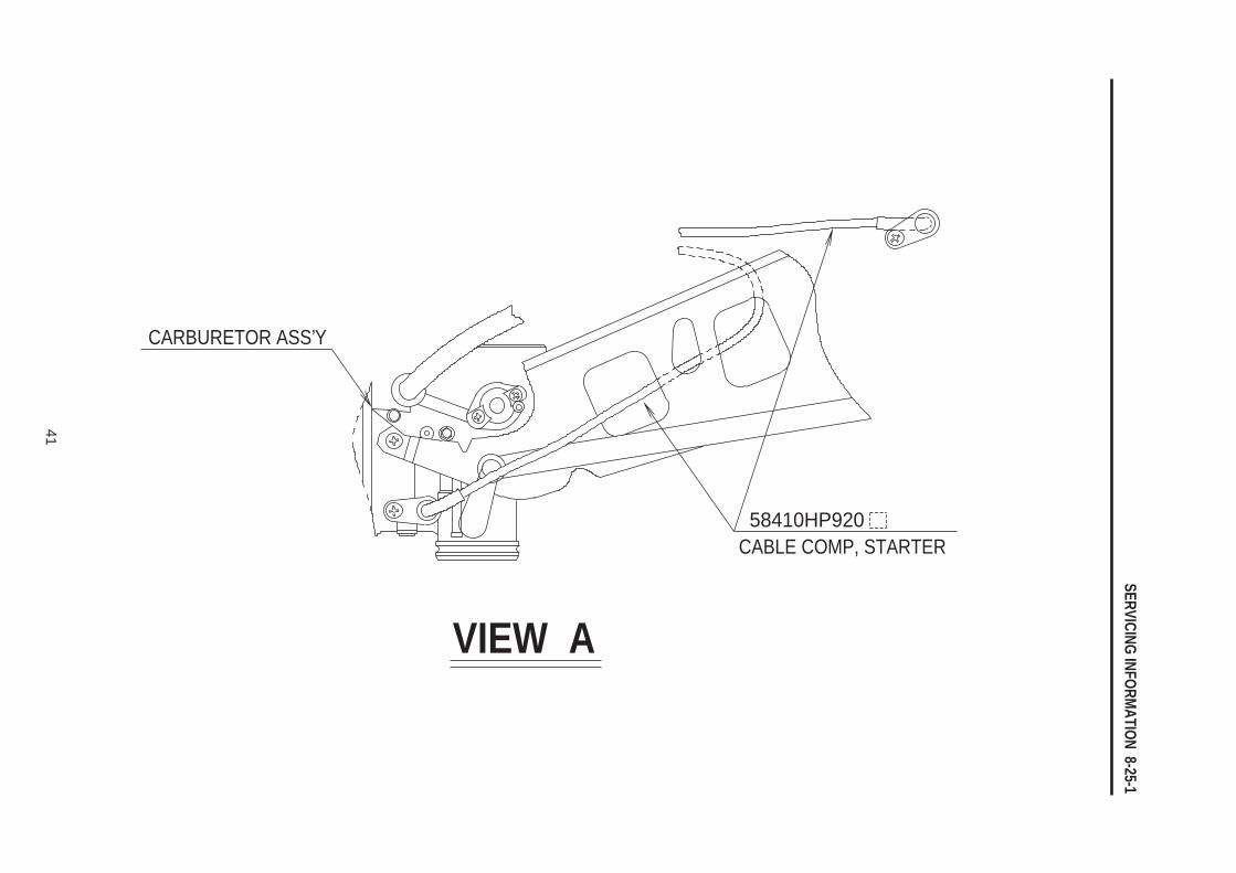
SERVICING INFORMATION 8-25-1
41
CARBURETOR ASS’Y
58410HP920CABLE COMP, STARTER
VIEW A
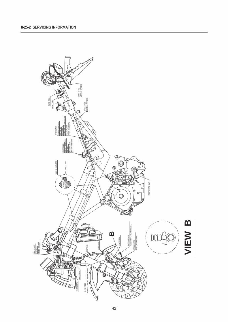
8-25-2 SERVICING INFORMATION
42
0940
7-14
403
0940
7-25
4A1
0940
7-20
406
0940
7-204
06
0940
7-204
06
5944
0HN9
10CL
AMP
COM
P, F
/T B
RAKE
HOS
E L
0940
3-09
301
5947
0HN9
10
0936
0H10
050
PROP
STA
ND S
/W
0940
7-14
403
0940
7-14
403
WIR
ING
HARN
ESS
WIR
ING
HARN
ESS
FUSE
(30A
)
FUSE
(15A
)
IGNI
TOR
0940
7-22
402
WIR
ING
HARN
ESS
MAG
NETO
REGU
LATO
RST
ARTI
NG M
OTOR
REL
AY09
407-
1440
3
WIR
ING
HARN
ESS
FRAM
EW
ELDI
NG C
LAM
PW
IRIN
G HA
RNES
SM
AGNE
TONE
UTRA
L S/
WPR
OP S
TAND
S/W
NEUT
RAL
S/W
PROP
STA
ND S
/W
BOLT
, BRA
KE F
LUID
HOSE
COM
P, F
RONT
BRA
KE L
VIEW
B
HARN
ESS
SPEE
D SE
NSOR
B
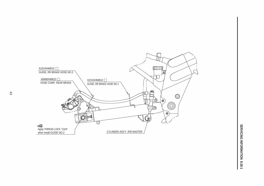
SERVICING INFORMATION 8-26-1
43
CYLINDER ASS’Y, R/R MASTER
61610HM810
69480HM810
GUIDE, RR BRAKE HOSE NO.2
61510HM810GUIDE, RR BRAKE HOSE NO.1HOSE COMP, REAR BRAKE
Apply THREAD LOCK "1324" when install GUIDE NO.2
8-26-2 SERVICING INFORMATION
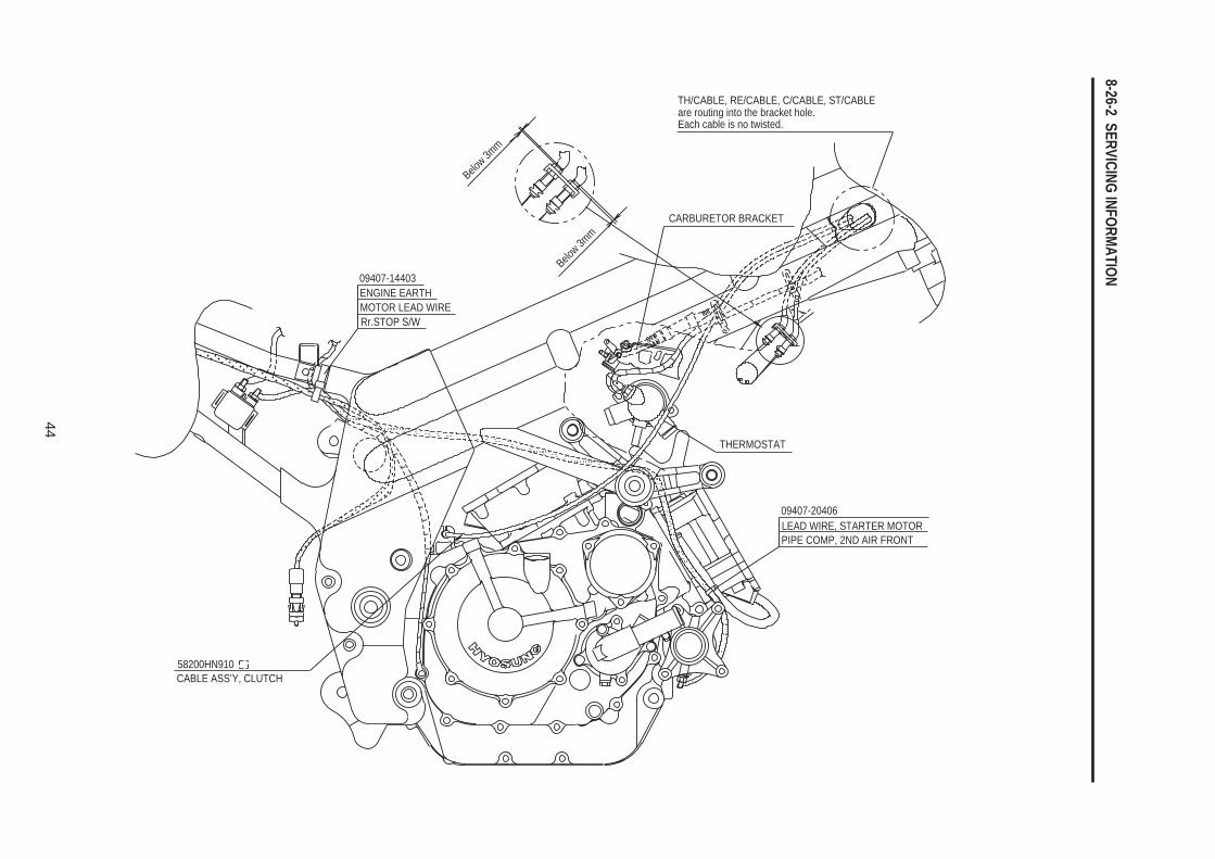
44
TH/CABLE, RE/CABLE, C/CABLE, ST/CABLE
CARBURETOR BRACKET
09407-14403
THERMOSTAT
09407-20406LEAD WIRE, STARTER MOTOR
58200HN910CABLE ASS’Y, CLUTCH
PIPE COMP, 2ND AIR FRONT
ENGINE EARTHMOTOR LEAD WIRERr.STOP S/W
Below 3m
m
Below 3m
m
are routing into the bracket hole.Each cable is no twisted.
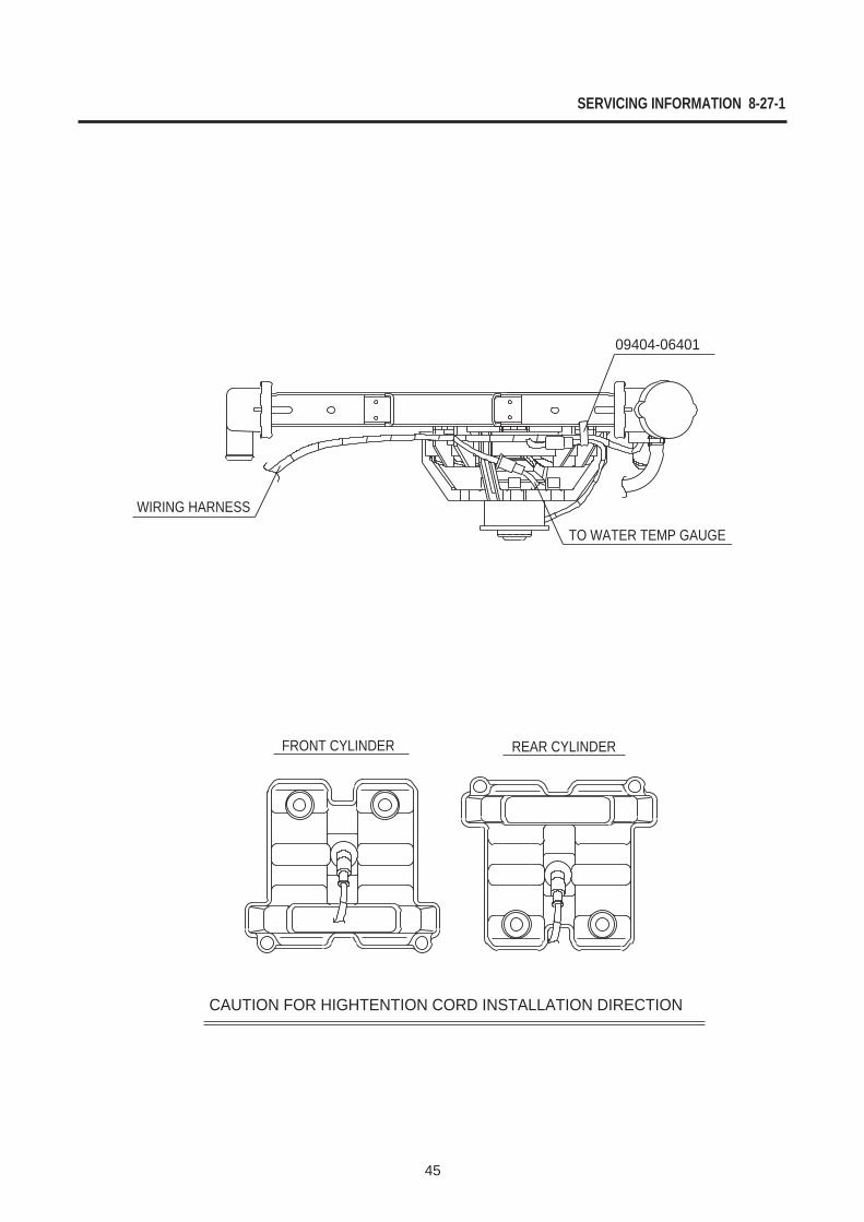
SERVICING INFORMATION 8-27-1
45
09404-06401
TO WATER TEMP GAUGE
WIRING HARNESS
FRONT CYLINDER REAR CYLINDER
CAUTION FOR HIGHTENTION CORD INSTALLATION DIRECTION
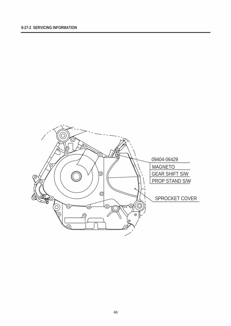
8-27-2 SERVICING INFORMATION
46
09404-06429MAGNETOGEAR SHIFT S/WPROP STAND S/W
SPROCKET COVER
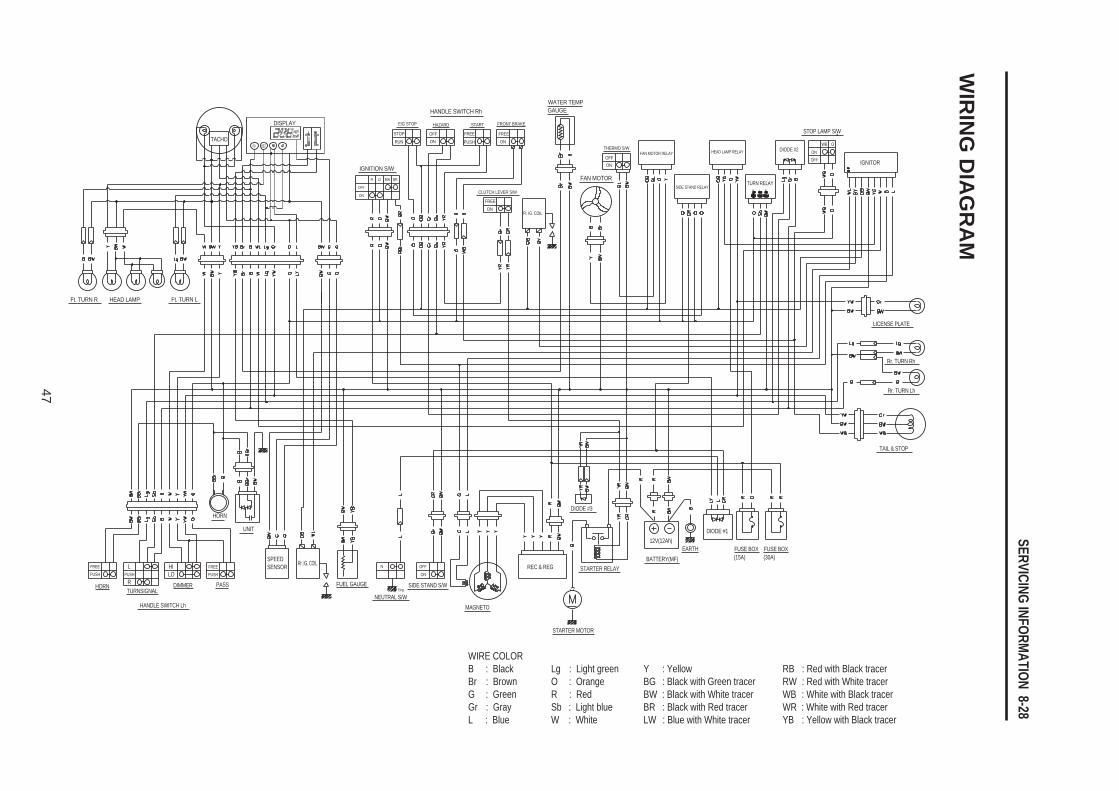
SERVICING INFORMATION 8-28
47
WIRE COLORB : Black Lg : Light green Y : Yellow RB : Red with Black tracerBr : Brown O : Orange BG : Black with Green tracer RW : Red with White tracerG : Green R : Red BW : Black with White tracer WB : White with Black tracerGr : Gray Sb : Light blue BR : Black with Red tracer WR : White with Red tracerL : Blue W : White LW : Blue with White tracer YB : Yellow with Black tracer
WIR
ING
DIA
GR
AM
Ft. TURN R HEAD LAMP
HANDLE SWITCH Rh
IGNITION S/W
OFF
ON
R O BW BR
HAZARDE/G STOP START
CLUTCH LEVER S/W
Ft. IG. COIL
FREEON
FRONT BRAKE
THERMO S/WFAN MOTOR RELAY
SIDE STAND RELAY
HEAD LAMP RELAY
TURN RELAY
DIODE #2
STOP LAMP S/W
IGNITOR
LICENSE PLATE
Rr. TURN Rh
Rr. TURN Lh
TAIL & STOP
FUSE BOX
DIODE #1
BATTERY(MF)STARTER RELAYREC & REG
MAGNETO
SIDE STAND S/W
NEUTRAL S/W
FUEL GAUGE
Rr. IG. COILSPEEDSENSOR
UNIT
HORN
PASS
HANDLE SWITCH Lh
TURNSIGNALHORN DIMMER
FREEPUSH
HILPUSH
FREEPUSH
RLO
Eng.
OFFON
N
STARTER MOTOR
12V(12Ah)EARTH
DIODE #3
(15A)FUSE BOX(30A)
ON
WB O
OFF
B L E
FAN MOTOR
OFFON
WATER TEMPGAUGE
FREE FREEONPUSH
STOP
RUNOFFON
Ft. TURN L
TACHO
DISPLAY
Prepared by
HYOSUNG MOTORS & MACHINERY INC.
1st Ed. APR. 2005.
Manual No. 99000-94910Printed in Korea