hydrovision 2014 conference design and construction of … 2014 - design and... · design and...
TRANSCRIPT

1
HydroVision 2014 Conference
Design and Construction of the 45 MW Kokish River Hydroelectric Project in British Columbia, Canada
Egbert J. Scherman, P. Eng., Specialist Engineer, Knight Piésold Ltd.
Sam R. Mottram, P. Eng., Managing Principal – Power Services, Knight Piésold Ltd.
ABSTRACT This presentation will cover the design innovations and lessons learned from the detailed design and construction of the Kokish River Hydroelectric Project recently constructed in the northern part of Vancouver Island located in British Columbia, Canada. This hydroelectric facility is a private sector development by Kwagis Power, a limited partnership of Brookfield Renewable Energy Group and the ‘Namgis First Nation that was awarded an energy purchase agreement by BC Hydro in an open call for clean energy. The project will generate up to 45 MW of clean renewable energy that will be delivered to the British Columbia electrical grid, with an annual energy production capacity of roughly 140 GWh, enough electricity to power close to 13 000 homes.
The Kokish River Hydroelectric project is a run‐of‐river project with a maximum design generation flow of 25 m³/s and operating head of 238 m. Peter Kiewit Infrastructure Co. was awarded an EPC Contract for the design and construction of the project with Knight Piésold Ltd. appointed the Design Engineer for the project.
The terrain, climate and permitting constraints presented numerous challenges that were all overcome with some innovative design solutions and a close working relationship between the Owner, Contractor and Design Team. These included:
dealing with migratory Salmon and Stealhead that are present throughout the diversion reach of the project, both during construction diversion and operation;
a diversion weir with the world’s largest capacity Coanda screen capable of regulating water flow depth over the screen to ensure emerging salmon fry safe passage over the screens;
a 70 metre long vertical slotted fish ladder that allows continuous migration around the diversion weir for both resident trout populations and migrating salmon;
hydraulic model testing of the entire diversion weir, intake structure and fish ladder;
a 1 474 m long buried HDPE low pressure penstock connected to a 7 703 m long buried, high pressure steel penstock, using soil restraint to eliminate expensive concrete anchor blocks;
2
a surface powerhouse housing four vertical axis six‐jet Pelton type turbine-generator units capable of handling the long duration flow ramping rates associated with the project;
a Powerhouse tailrace channel fish fence, designed to prevent upstream migrating Salmon and Steelhead from entering the tailrace; and
a sophisticated in-stream flow measuring and flow ramping protocols.
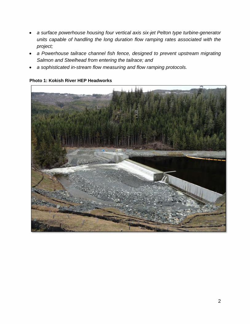
Photo 1: Kokish River HEP Headworks
3
1 INTRODUCTION
1.1 BACKGROUND The construction of the Kokish River Hydroelectric Project was undertaken by the Peter Kiewit Infrastructure Co. (Kiewit) in an Engineer-Procure-and-Construct (EPC) venture with the Owner (Kwagis Power Limited Partnership) with Knight Piésold Ltd. appointed as the Design Engineer for the project.
The Kokish River Hydroelectric Project is a 45 MW Run-of-River hydroelectric project located approximately 15 km east of Port McNeill, on the northeast coast of Vancouver Island, British Columbia, Canada.
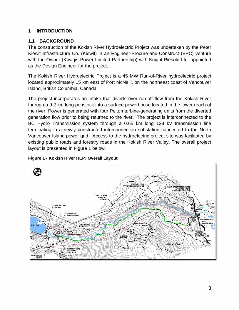
The project incorporates an intake that diverts river run-off flow from the Kokish River through a 9.2 km long penstock into a surface powerhouse located in the lower reach of the river. Power is generated with four Pelton turbine-generating units from the diverted generation flow prior to being returned to the river. The project is interconnected to the BC Hydro Transmission system through a 0.65 km long 138 kV transmission line terminating in a newly constructed interconnection substation connected to the North Vancouver Island power grid. Access to the hydroelectric project site was facilitated by existing public roads and forestry roads in the Kokish River Valley. The overall project layout is presented in Figure 1 below.
Figure 1 - Kokish River HEP: Overall Layout

4
HYDROELECTRIC FACILITY MAIN FEATURES AND DESIGN PARAMETERS
The Kokish River hydroelectric generation facility has the following main features and design parameters:
Water Source: Kokish River
Project Operation: Run-of-river
Nameplate Plant Capacity: 45 MW
Plant Design Flow: 25.00 m³/s
Intake Design Flood: 1:200-year Peak Instantaneous: 719 m³/s
Powerhouse Design Flood: 1:500-year Peak Instantaneous: 1014 m³/s
Gross Head: 238.20 mwc (EL. 254.8 msl to EL. 16.6 msl)
Net Head: 204.03 mwc
Environmental Flow (IFR): Seasonally ranging from 3.4 m³/s to 12 m³/s
Headworks: Reinforced concrete diversion weir, intake structure and fish ladder with earthfill embankment flank
Penstock: Lined and coated steel and profiled wall HDPE pipe totalling 9 177 m in length, with nominal pipe diameters varying from 3 048 to 2 733 mm
Powerhouse: Concrete substructure with structural steel metal cladded superstructure and steel roof, equipped with an overhead crane
Turbine Equipment: Four vertical axis six-jet Peltonl turbine units rated at 11.25 MW each
Generator Equipment: Four direct coupled synchronous generators rated at 13.8 kV, 12.5MVA
Switchyard: 13.8 kV to 138 kV Step-up transformer with 138 kV breaker and terminal structure
Transmission Line: 138 kV Transmission line to 138 kV interconnection substation with BC Hydro transmission grid
Transmission Line Length: 0.65 km
Conductor: IBIS 397 kcmil, ACSR
Tower Structures: Treated Douglas Fir wood single pole structures
Access: Access to all project facilities by the Beaver Cove Road and the Kokish River valley forestry roads.

5
2 HEADWORKS The primary design objective of the headworks, as for any run-of-river hydropower facility, is to create adequate ponding of the water source for diverting flow to the intake structure and penstock while allowing for flood flows to be safely discharged during flood events (up to the design flood capacity), without major structural damage to any of the permanent works.
The primary functions of the headworks are as follows:
Facilitate the reliable extraction of the generation flow into the intake and penstock through a variable range of river flow conditions.
Effectively limit debris and sediment larger than the screen slot width from entering the water conveyance system.
Effectively and accurately regulate and measure both generation flow and bypass flow (including the IFR).
Sustain existing river bed morphology, and minimize the need for dredging or other mechanical sediment removal methods, and
Accommodate the upstream and downstream passage of fish through the provision of fish migration passage and bypass flow systems reviewed and accepted by fisheries professionals.
The headworks layout adopted for the Kokish HEP consist of three main components; the diversion weir structure, the intake structure and a fish ladder. The headworks arrangement is presented on Figure 2 below.
Figure 2 - Kokish River HEP Headworks
A purpose-built hydraulic model of the Kokish River HEP headworks was tested in a hydraulic laboratory to verify sediment and debris migration past the diversion weir, to confirm operational requirements and model other functions such as balancing of

6
fisheries bypass flows, diversion of flows towards the intake. Submergence requirements were also tested in the hydraulic model. The hydraulic model of the headworks, built to 1:12 scale, was tested in Northwest Hydraulic Consultants’ laboratory facilities in North Vancouver, BC. The hydraulic model is presented in Photo 2 below.
Photo 2: Kokish River HEP Headworks - Hydraulic Model
2.1 TEMPORARY DIVERSION CHANNEL In order to construct the intake headworks, the Kokish River had to be diverted around the proposed location. Particular challenges for the temporary diversion works included:
High value fish habitat of the river section.
Construction work had to be performed in a short duration fish window.
Lack of access on the far bank (western side) and scheduling of construction staging.
Had to be designed for significant flood flows, even for temporary works.
Temporary diversion works had to provide conditions to facilitate year round fish passage during construction of the project.
Five species of Pacific salmon, summer-run and winter-run steelhead, rainbow trout, coastal cutthroat trout, kokanee and Dolly Varden char occur in the Kokish watershed. Salmon migration into the Kokish River mainly occurs between July and November with
7
peak counts generally in September. The environment approval for the project states that the project is not allowed to significantly impact fish habitat, hence the temporary diversion channel had to be constructed to accommodate year round fish migration past the headworks construction site and the channel could only be constructed during a period that would have minimal impacts on any of the fish species, called “fish window”.
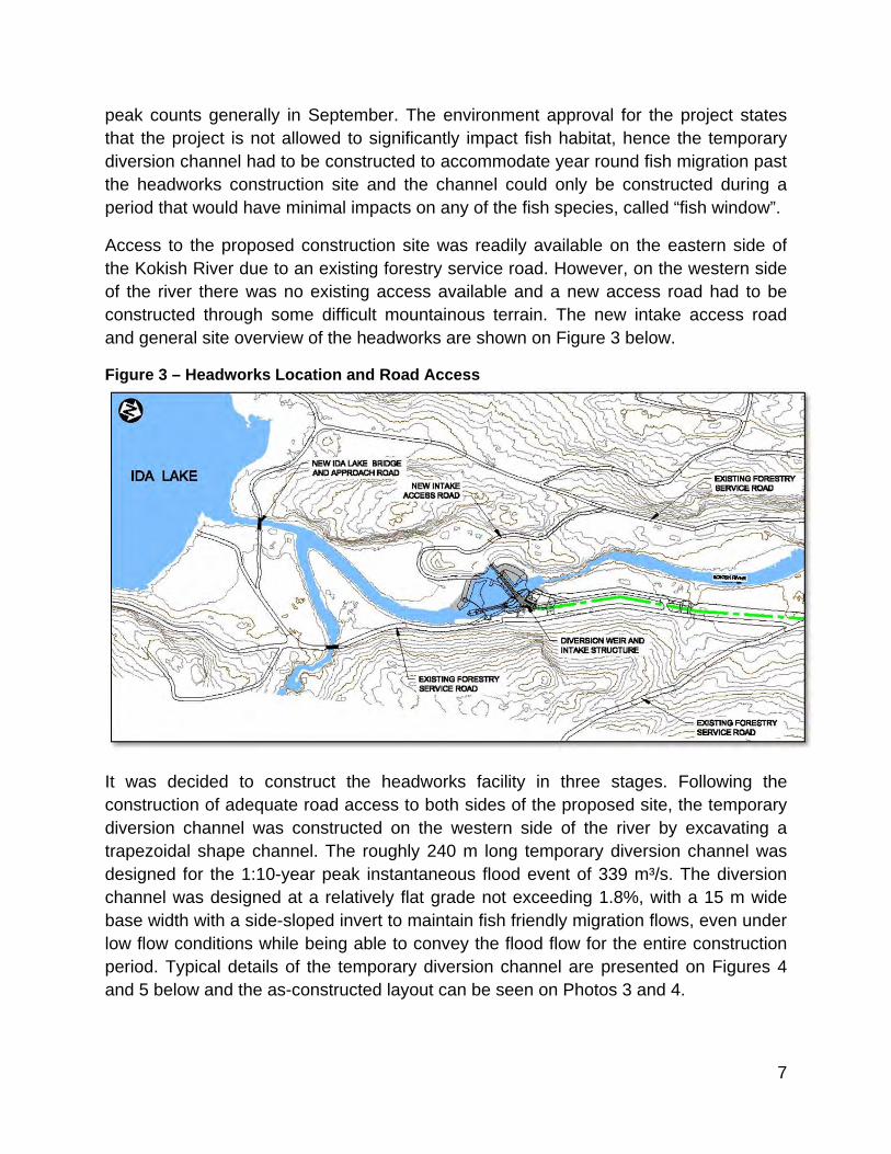
Access to the proposed construction site was readily available on the eastern side of the Kokish River due to an existing forestry service road. However, on the western side of the river there was no existing access available and a new access road had to be constructed through some difficult mountainous terrain. The new intake access road and general site overview of the headworks are shown on Figure 3 below.
Figure 3 – Headworks Location and Road Access
It was decided to construct the headworks facility in three stages. Following the construction of adequate road access to both sides of the proposed site, the temporary diversion channel was constructed on the western side of the river by excavating a trapezoidal shape channel. The roughly 240 m long temporary diversion channel was designed for the 1:10-year peak instantaneous flood event of 339 m³/s. The diversion channel was designed at a relatively flat grade not exceeding 1.8%, with a 15 m wide base width with a side-sloped invert to maintain fish friendly migration flows, even under low flow conditions while being able to convey the flood flow for the entire construction period. Typical details of the temporary diversion channel are presented on Figures 4 and 5 below and the as-constructed layout can be seen on Photos 3 and 4.

8
Figure 4 – Temporary Diversion Channel Plan
Figure 5 – Temporary Diversion Channel Section

9
Photo 3 – Temporary Diversion Channel
Photo 4 – Temporary Diversion Channel During Construction of Intake

10
2.2 DIVERSION WEIR The diversion weir consists primarily of a reinforced concrete weir with an inner spillway section fitted with Coanda screen panels and a collector channel collecting the diverted generation flow underneath the screens. The diversion weir is connected to the intake structure on the one side and terminates in an overflow weir wall on the other side.
The diversion weir spillway and overflow weir are designed to accommodate the 1:500-year peak instantaneous return period flood (1014 m³/s) without structural damage to the headworks components. The downstream end of the diversion weir was protected against erosion and scouring, so as not to affect the stability of the structure. The length of the overflow weir wall is a function of the available distance between the spillway and adjacent river bank and its height is designed such that the full diverted generation flow will pass directly over the spillway and Coanda screen before any flow is spilled over the overflow weir on the left bank. This is done to ensure 100% capturing of the river run-off flow (minus permitted environment flows) to be utilized for generation before any spilling of excess water at the headworks.
The diversion weir arrangement incorporates Coanda screen panels inside the spillway section, capable of screening generation flow to the collector channel below the spillway section. The collector channel conveys the screened flow from underneath the spillway screens into the intake structure. The screens prevent debris, course sediment and fish from entering the generation flow. Screened material and fish are passed over the spillway into the river section below the weir. The Coanda screen design follows the design guidance laid out by the U.S. Department of the Interior Bureau of Reclamation (USBR). The slot opening between the Coanda screen wedge wires is 2.0 mm and the screen approach was designed to operate efficiently up to the 1:2-year peak instantaneous flood event. The support structure underneath the screens were incorporated and designed to withstand impacts from bedload and debris during design flood conditions. The screen was installed in separate uniform panels, sloping downstream at an angle which will reduce the force of impact from boulders or other debris passing over the weir. The total length of the spillway with Coanda screen panels is 58.61 metres. The throughput capacity of the spillway screens is 25 m³/s, which is believed to be the highest capacity Coanda screen installation in the World for a hydropower project.
Located inside the remnant of the pre-construction river channel located below the diversion weir, a sluice channel was designed to bypass flows underneath the headworks. The sluice channel was outfitted with two slide gates which were sized to provide a fully redundant environmental Instream Flow Release (IFR) discharge system.

11
The main function of the sluice channel gates is as follows:
To ensure a controlled release of the environmental IFR’s
To allow for scouring of sediments deposited in the headpond during high flow events, and
To provide low level outlet capability i.e. bypass the overflow spillway during maintenance service periods (i.e. for servicing of the diversion weir (spillway screens and overflow sections), intake structure or fish ladder).
The diversion weir and sluice channel outlet is presented on Photo 5 below.
Photo 5 – Diversion Weir with Sluice Channel Outlet and Fish Ladder Entrance on Nearside

12
2.3 INTAKE STRUCTURE The intake structure for the Kokish River HEP consists of a sediment collection trough and purging facility, intake gallery with secondary trashrack on top of a submerged weir, head gate and vent shaft, transition structure to penstock and various other mechanical and electrical equipment. The intake structure is designed for the maximum generation flow while economically excluding entrained air and sediment, as much as possible. The intake structure arrangement is shown on Figure 6 below.
Figure 6 – Intake Structure Plan
Screened flow, collected in the collector channel from the diversion weir, is conveyed over the sluice channel and enters the intake structure reservoir box through an intake portal. Once the screened water overtops the submerged weir, located downstream of the sediment collection trough, it passes through the trash rack screen located on top of the submerged weir and is conveyed through the head gate opening towards the square-to-round transition structure connected to the penstock. The water reservoir is required for submergence, de-aeration, adding operational stability inertia and minor storage purposes.
13
The intake structure is enclosed by cast-in-place and pre-cast concrete roof panels. Access within the intake structure is achieved by means of manhole access, with access ladders and a walkway platform located adjacent to the trash rack screen.
A bell-mouth shaped transition structure downstream of the control head gate is used to transition the generation flow through the square gate opening to the circular shape of the penstock.
The Instream Flow Release (IFR) discharge is released from the headworks by various mechanisms, which includes a number of redundant systems. The required IFR discharge (as permitted) for the project varies seasonally between 3.4 m³/s and 12 m³/s throughout the year, hence the IFR discharge facilities had to be designed to be adjustable in order to match the required discharge flow.
The design of the IFR discharge equipment ensures that the permitted in-stream flow requirements are met in a manner consistent with the project’s Water License conditions and the Fisheries Authorization. The headworks are able to discharge the required IFR flow by means of a combination of the following equipment:
Continuous fish ladder discharge flow
Opening of auxiliary flow discharge pipes to augment the fish ladder flow at the stilling chamber and fish ladder entrance
Spilling over the spillway and out of the bottom of the Coanda screen by means of plant control
Opening of a single sluice channel slide gate to discharge additional flow to augment flows from other devises or to release the entire maximum IFR flow, as required
All discharged and spilled flow from the headworks are actively measured at a gauging station, located some 200 metres downstream of the intake, and connected in real-time to the plant’s control system.

14
2.4 FISH LADDER To facilitate the migration of fish around the diversion weir and intake structure, a fish ladder was designed and constructed as a wrap-around structure on the intake structure. A vertical slot fish ladder was used which consists of a series of interconnected pools, bypassing an obstruction (vertical slots in baffle walls). The vertical-slot type fish ladder has a proven track record and is very successful with native fish species.
The vertical slotted fish ladder was constructed from reinforced concrete cantilevering from the intake structure side walls with a base slab slope at 10% (1V:10H) which is slighter more gradual than the typical 14% used for similar type fish ladders. The slope was adjusted during the hydraulic model testing (Photo 6) to lower the velocity through the fish ladder channel creating a better fish migration environment. The discharge flow of the fish ladder is roughly 1.8 m³/s at the normal operating water levels in the headpond.
Photo 6 – Fish Ladder Hydraulic Model Test

15
The fish ladder has a deep (approx. 2.5 m) invert connection in the headpond, being impounded by the diversion weir, and discharges into a stilling well at the foot of the fish ladder, located adjacent to the sluice channel. The openings (vertical slots) in the stilling well walls ensure connectivity to the sluice channel discharge flow and a downstream fish channel connecting with the Kokish River. Fish attractant flow can be augmented by means of two Ø500 mm auxiliary flow discharge pipes that are separately controlled by knife gate valves to discharge additional flow up to 1.4 m³/s to the fish ladder’s stilling chamber and entrance. The operation of the Fish Ladder can be seen in Photo 7 below
Photo 7 – Fish Ladder Channel in Operation

16
3 PENSTOCK The penstock for the Kokish River HEP consists in part of a low pressure pipe section, a surge facility (surge shaft) and a high pressure pipe section ending in a quadfurcation manifold at the powerhouse. The low pressure section consist of some 1 474 m long by Ø3 050 mm and Ø2 740 mm profiled wall high density polyethylene (HDPE) pipe, primarily used due to lower material cost and quicker installation. The remainder of the penstock consists of 7 703 m long by Ø2 749 mm carbon steel pipe that was coated and lined with a polyurethane paint system for corrosion protection.
The penstock design optimization required that the conveyance system headloss and the total dynamic head, be evaluated and balanced against the penstock pipe supply and associated installation costs, considering different pipe sizes, as well as taking into account the value of the energy to be generated by the project in the most cost effective arrangement.
For the penstock alignment, the pipe was routed along existing forestry roads whenever possible to take advantage of the cost savings associated with the use of existing access. The remainder of the penstock (primarily lower the reaches down to the powerhouse) was routed along virgin natural terrain at varying grades. The maximum grade at which the penstock was constructed in a buried condition was 38.5%. The penstock longitudinal section is presented in Figure 7 below indicating the steeper grades towards the powerhouse.
Figure 7 – Penstock Longitudinal Profile Section
The penstock alignment was optimized during detailed design in order to reduce bends, avoid hazardous natural terrain areas as much as possible while allowing construction access and minimizing earthworks volumes. A significant number of vertical and horizontal bends were necessary to fit the mountainous topography with steep hill side slopes, located in various types of soil (sand, gravel & till) and rock material with very limited access considering the size of pipe required for the project.

17
The penstock terminates and is hydraulically connected to the powerhouse by means of a quadfurcation (four branch) manifold. The manifold design required optimization of the hydraulic headloss versus the material and installation cost thereof. The manifold was encased in reinforced concrete integrated with the powerhouse substructure and directly connected to the four turbine inlet valves located inside the powerhouse, while also providing structural restraint of the four valves. See Photo 8 below for the quadfurcation manifold during construction.
Photo 8 – Penstock Quadfurcation Manifold (under construction)
3.1 PIPE SUPPORT USING SOIL-RESTRAINT A total number of 51 bends (mitre bends) were required along the 9.2 km length of the penstock, in order to route the penstock through the mountainous terrain and to eliminate natural terrain hazards as much as possible. During detailed design, the penstock design focused to eliminating all expensive concrete anchors blocks, used for restraining the penstock pipe at directional changes in the alignment, in order to balance the thrust forces. The design successfully managed to eliminate all concrete anchor blocks while only relying on soil-restraint to support and restrain the pipe in a buried condition along its entire length. This was done to reduce cost and avoid concentrated loads on the pipe, which typically occurs at anchor blocks.
The buried pipe arrangement provides support to the penstock pipe by the surrounding trench backfill material. The compacted backfill material provides restraint in both the
18
vertical, horizontal and axial direction in order to give the pipe additional stiffness and structural resistance capacity. The soil-restraint modeling for the Penstock design, is generally focused on directional changes (bends) where large hydraulic, pressure and thermal thrust induced forces develop on and inside the pipe wall. Soil resistance (modeled as soil springs) is used to resist/restrain the thrust forces on the pipe. The soil springs are modeled by a finite element model (FEM) based on American Lifeline Association (ALA) guidelines. The FEM pipe-soil interaction model used in the design, accounts for the pipe axial and bending resistance, the longitudinal resistance of the soil caused by friction and the lateral and vertical resistance of the soil.
The lateral and vertical resistance of the soil is derived from the following soil resistance components: Horizontal soil bearing capacity (lateral) Soil passive resistance (lateral) Soil foundation bearing resistance (vertical) Soil cover uplift resistance (vertical)
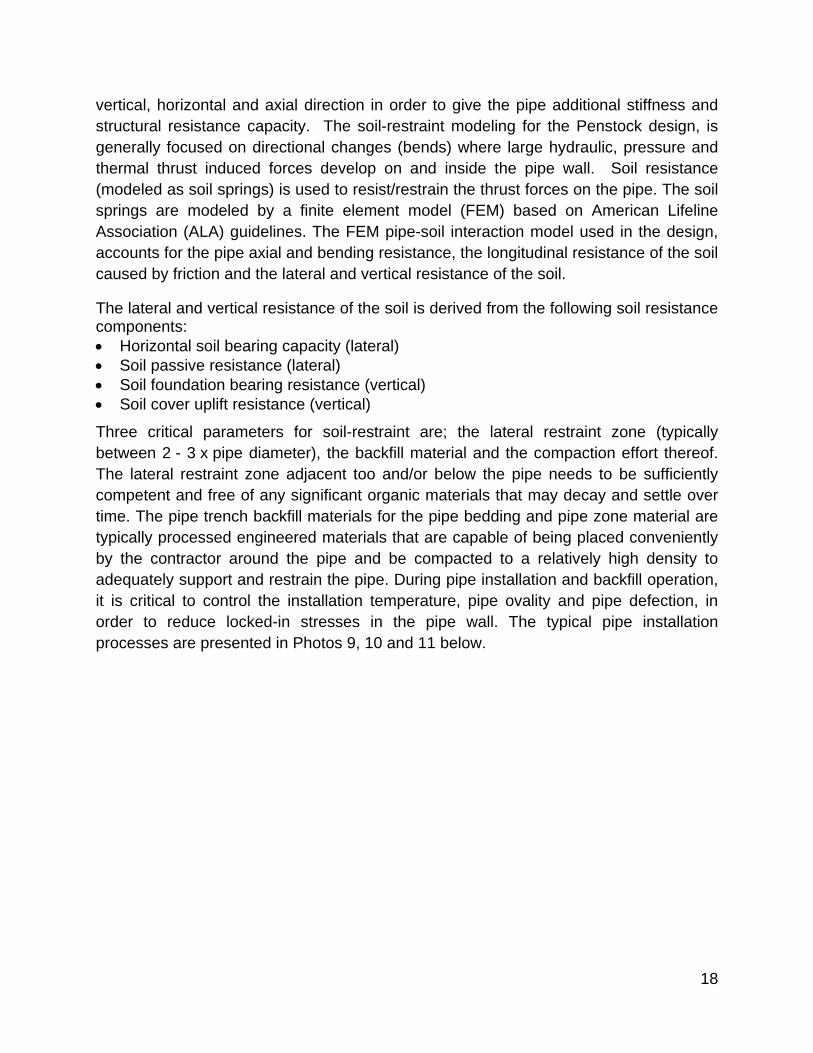
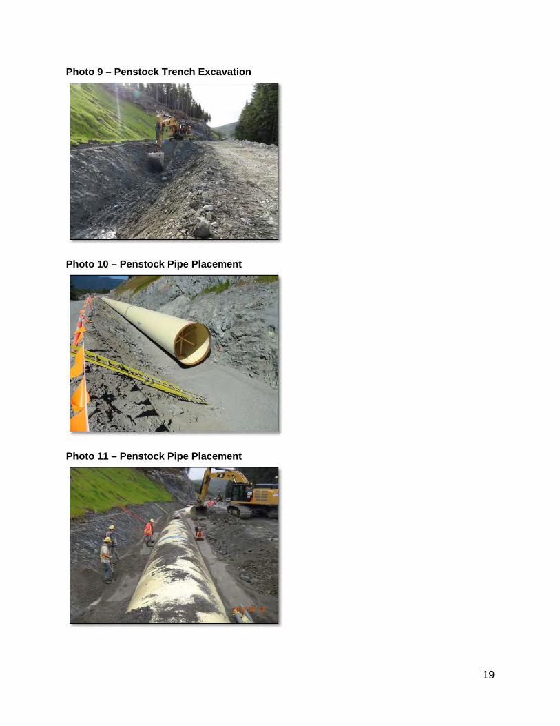
Three critical parameters for soil-restraint are; the lateral restraint zone (typically between 2 - 3 x pipe diameter), the backfill material and the compaction effort thereof. The lateral restraint zone adjacent too and/or below the pipe needs to be sufficiently competent and free of any significant organic materials that may decay and settle over time. The pipe trench backfill materials for the pipe bedding and pipe zone material are typically processed engineered materials that are capable of being placed conveniently by the contractor around the pipe and be compacted to a relatively high density to adequately support and restrain the pipe. During pipe installation and backfill operation, it is critical to control the installation temperature, pipe ovality and pipe defection, in order to reduce locked-in stresses in the pipe wall. The typical pipe installation processes are presented in Photos 9, 10 and 11 below.
19
Photo 9 – Penstock Trench Excavation
Photo 10 – Penstock Pipe Placement
Photo 11 – Penstock Pipe Placement

20
3.2 PIPE IN ROAD DESIGN Due to significant natural terrain challenges (with associated costs), the pipe alignment was refined and adjusted during construction to a location directly underneath the Kokish Main forestry service road (FSR), for some 740 m thereof.
The Kokish Main FSR is a resource road, used mainly for logging activities and most of the logging vehicles are off-high vehicles that far exceed the legal road-going vehicle axle loading. The design vehicle for the Kokish Main FSR, is a L-165 off-highway logging truck, as defined by the British Columbia Ministry of Forest, Land and Natural Resource Operations` Forestry Service Bridge Design and Construction Manual. The L-165 logging truck has axle loads of 396 kN spaced 1.68 m apart, which is more than double legal road-going vehicle loads (typically 142 kN for AASHTO HS20).
The re-alignment of the penstock for this 740 m stretch therefore required special design consideration to protect the pipe from the extreme vehicle loads. A number of design alternatives where considered and developed for consideration by the contractor. The final design selected by the contractor, entailed the incorporation of a cement treated fill (CTF) sub-base underneath the road running surface of the road to support the vehicle axle load and span across the pipe while distributing the vehicle loading to the adjacent soil columns either side of the pipe. A typical section of the design can be seen in Figure 8 and the construction thereof is presented in Photo 12 below.
Figure 8 – Penstock in Road Section: Typical Detail

21
Photo 12 – Penstock in Road Section Construction
22
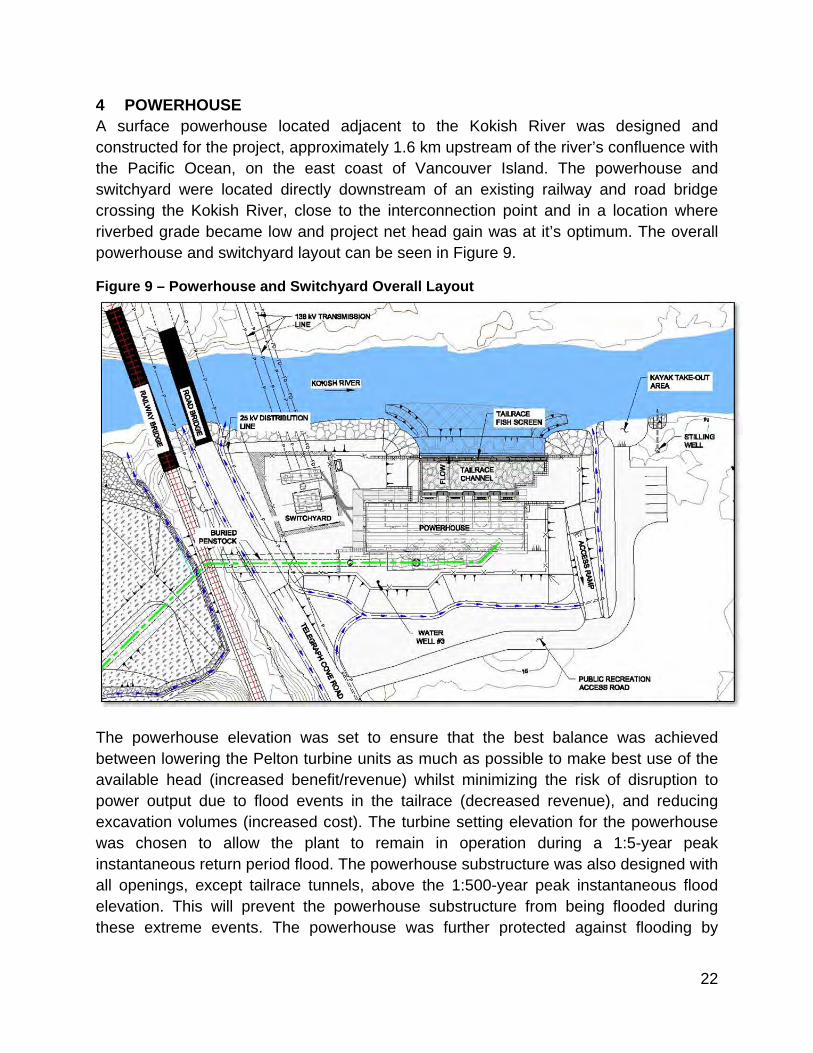
4 POWERHOUSE A surface powerhouse located adjacent to the Kokish River was designed and constructed for the project, approximately 1.6 km upstream of the river’s confluence with the Pacific Ocean, on the east coast of Vancouver Island. The powerhouse and switchyard were located directly downstream of an existing railway and road bridge crossing the Kokish River, close to the interconnection point and in a location where riverbed grade became low and project net head gain was at it’s optimum. The overall powerhouse and switchyard layout can be seen in Figure 9.
Figure 9 – Powerhouse and Switchyard Overall Layout
The powerhouse elevation was set to ensure that the best balance was achieved between lowering the Pelton turbine units as much as possible to make best use of the available head (increased benefit/revenue) whilst minimizing the risk of disruption to power output due to flood events in the tailrace (decreased revenue), and reducing excavation volumes (increased cost). The turbine setting elevation for the powerhouse was chosen to allow the plant to remain in operation during a 1:5-year peak instantaneous return period flood. The powerhouse substructure was also designed with all openings, except tailrace tunnels, above the 1:500-year peak instantaneous flood elevation. This will prevent the powerhouse substructure from being flooded during these extreme events. The powerhouse was further protected against flooding by

23
having all its mechanical and electrical equipment located above (or protected) from the 1:200-year peak instantaneous flood event water elevation.
Inside the powerhouse, four vertical axis six‐jet Pelton turbines with accompanying synchronous generators are located, as well as the associated turbine inlet valves and all other mechanical and electrical balance-of-plant and auxiliary equipment. The powerhouse is provided with a loading bay, maintenance area and a control room. The building superstructure includes a full size 65 metric tonne overhead bridge crane for the erection and maintenance of all major plant equipment. The powerhouse consists of an externally cladded steel-frame building on a reinforced concrete substructure with the penstock quadfurcation and lined tailrace channel connected to it. The powerhouse layout is presented in Figure 10 below.
Figure 10 – Powerhouse Layout
The powerhouse foundation is designed as a raft foundation since competent bedrock was much deeper than the foundation excavation elevations of the concrete substructure, in this particular location. The foundation preparation for the project consisted of removing all unsuitable foundation material underneath the substructure and backfilling up to foundation level with engineered fill i.e. compacted structural fill. The powerhouse substructure foundation slab was designed to accommodate and

24
support the superstructure and generating equipment as well as to resist roto-dynamic forces and vibrations caused by the generating equipment. Construction progress is presented in Photos 13 and 14.
Photo 13 – Construction of Powerhouse, Switchyard and Penstock
Photo 14 – Construction of Powerhouse, Switchyard and Penstock

25
4.1 TAILRACE CHANNEL The tailrace channel conveying the generation flow from the powerhouse back to the Kokish River’s natural watercourse, consists of a riprap armoured channel constructed with concrete block retaining walls and a fish screen located at the end of the tailrace channel. The construction of the tailrace channel was done in a manner that minimizes clearing and disturbance within the riparian zone.
The entire channel was lined with an impermeable liner to prevent water loss from the interior of the channel that could damage aquatic life that may inhabit the powerhouse tailrace. The tailrace channel invert was located slightly below the lowest known water level in the Kokish River as to remain wet (flooded), even under extreme low water conditions. The tailrace channel upstream of the fish screen is presented in Photo 15.
Part of the design objective for the tailrace layout was to create conditions downstream of the tailrace outlet such that the identified migratory fish species that are present in the Kokish River, are encouraged to migrate up the river, past the tailrace, in their traditional manner.
Photo 15 – Powerhouse Tailrace (back flooded)
26
4.2 FISH SCREEN FENCE A fish screen fence was located on the downstream side of the tailrace channel at the confluence with the Kokish River, to prevent fish from being stranded while trying to migrate into the tailrace channel. It was designed and orientated to encourage the fish to continue swimming past the tailrace fish fence and continue on their upstream migration.
Flow conditions with the necessary upstream attraction flow and white-water noise were required to encourage the fish to investigate and migrate upstream, rather than staying downstream at the fish screen fence and tailrace due to the generation flow being release from the facility. Photo 16 illustrates the flow conditions downstream of the constructed fish screen fence.
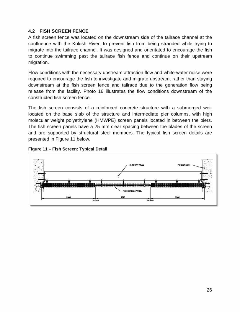
The fish screen consists of a reinforced concrete structure with a submerged weir located on the base slab of the structure and intermediate pier columns, with high molecular weight polyethylene (HMWPE) screen panels located in between the piers. The fish screen panels have a 25 mm clear spacing between the blades of the screen and are supported by structural steel members. The typical fish screen details are presented in Figure 11 below.
Figure 11 – Fish Screen: Typical Detail

27
Photo 16 – Fish Screen Fence with Natural Upstream Attraction Flow Visible

28
5 SWITCHYARD An electrical switchyard was located adjacent to the powerhouse to step-up the generation voltage (13.6 kV) to a suitable transmission voltage (138 kV). The switchyard was located as close as possible to the powerhouse in order to reduce conductor losses from the generators to the step-up transformer.
The switchyard was constructed on engineered fill since the native material was found to be inadequate to support the transformer and terminal structure foundation loads. The foundation structure for all major tower structures, breaker and transformer were constructed using reinforced concrete. The final grade elevation of the switchyard was set to the 1:200-year peak instantaneous return period flood level. The switchyard is presented in Photo 17 below.
Photo 17 - Switchyard
6 TRANSMISSION LINE The 138 kV transmission line that connects the Kokish River generating facility with the point of interconnection at the newly constructed BC Hydro substation, is approximately 0.65 km long. The transmission line was constructed from single wood pole structures consisting of treated Douglas Fir poles that were between 27 to 33 m in length. The typical working span of the pole structures is approximately 100 m, along flat and low gradient terrain.
29
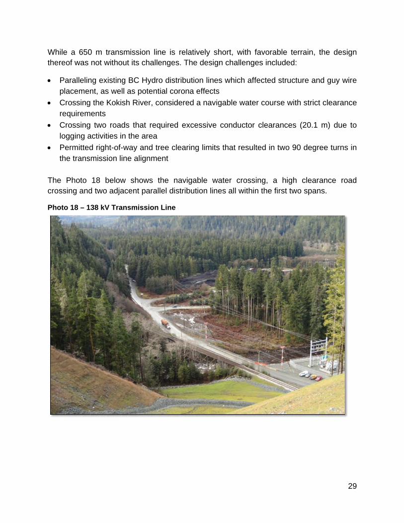
While a 650 m transmission line is relatively short, with favorable terrain, the design thereof was not without its challenges. The design challenges included:
Paralleling existing BC Hydro distribution lines which affected structure and guy wire placement, as well as potential corona effects
Crossing the Kokish River, considered a navigable water course with strict clearance requirements
Crossing two roads that required excessive conductor clearances (20.1 m) due to logging activities in the area
Permitted right-of-way and tree clearing limits that resulted in two 90 degree turns in the transmission line alignment
The Photo 18 below shows the navigable water crossing, a high clearance road crossing and two adjacent parallel distribution lines all within the first two spans.
Photo 18 – 138 kV Transmission Line

30
BIOGRAPHICAL SKETCH FOR EACH AUTHOR
Egbert Scherman, Specialist Engineer, P. Eng.
Mr. Scherman is a Civil/Structural Engineer with extensive experience in the design and construction of various structural and civil engineering projects with particular experience as a consulting engineer in the water resources, and hydroelectric industries. His experience in the power sector includes detailed design of numerous high head hydroelectric projects in North and South America and Africa. As design manager in the Vancouver office, he has been responsible for the detailed design of 13 hydro facilities in recent years. Mr. Scherman is a licenced professional engineer in the provinces of British Columbia, Alberta and Ontario in Canada and in South Africa.
[email protected] www.knightpiesold.com
Sam Mottram, Managing Principal, Power Services, P. Eng.
Mr. Mottram has over 22 years of experience in the management, design and development of hydroelectric and pumped storage projects for both private and public sector Clients in the energy and mining industries. He has a master’s degree in civil engineering and currently manages the Power Group for Knight Piésold Ltd. He has worked on more than 100 hydroelectric projects on five continents ranging in size from less than 1 MW to over 1,000 MW in size, including run of river hydro, pumped storage and conventional storage hydro. Mr. Mottram is a licenced engineer in the provinces of British Columbia, Yukon,
Saskatchewan, Manitoba and Ontario in Canada and in South Africa. [email protected] www.knightpiesold.com