hydrothermal characteristics and quality of alfalfa...
TRANSCRIPT

HYDROTHERMAL CHARACTERISTICS
AND QUALITY OF ALFALFA CUBES
DURING TRANSPORT
A Thesis Submitted to the College of
Graduate Studies and Research
in Partial Fulfillrnent of the Requirements
for the Degree of Doctor of Phi losophy
in the Department of Agricultural and Bioresource Engineering
University of Saskatchewan
Saskatoon
Mohammad Hadi Khoshtaghaza
C ~ L C 1997
O Copyright Mohammad Hadi Khoshtaghaza, 1997. Al1 rights reserved.

National Library l*l of Canada Bibliothèque nationale du Canada
Acquisitions and Acquisitions et Bibliographie Services senrices bibliographiques
395 Wellington Street 395, nie Wellington OtiawaON KlAON4 Ottawa ON K I A ON4 Canada Canada
Your file Vofm réference
Our file Nme rdlérence
The author has granted a non- exclusive licence allowing the National Library of Canada to reproduce, loaq distribute or seil copies of this thesis in microform, paper or electronic formats.
The author retains ownership of the copyright in this thesis. Neither the thesis nor substantid extracts from it may be printed or othenvise reproduced without the authorys permission.
L'auteur a accordé une licence non exclusive permettant à la Bibliothèque nationale du Canada de reproduire, prêter, distribuer ou vendre des copies de cette thèse sous la fome de microfiche/film, de reproduction sur papier ou sur format électronique.
L'auteur conserve la propriété du droit d'auteur qui protège cette thèse. Ni la thèse ni des extraits substantiels de celle-ci ne doivent ê e imprimés ou autrement reproduits sans son autorisation.
UNIVERSITY OF SASKATCHEWAN
College of Graduate Studies and Research
Submitted m partial fiilfillment
of the requirements for the
DEGREE OF DOCTOR OF PHEOSOPBY
Department of Agiculhu;ll and Bioresource Engineering College of Engineering
University of Saskatchewan
Examinhg Committee:
eecta/hw&&bWDean's Designate, Chair Coiiege of Graduate Studies and Research
Dr. D.I. N o m
Dr. S. Sokhansanj
Dr. G.J. Schoenau
Dr. B. Gossen
Dr. E.M. Barber
Dr. R. Ford
External Examiner:
Chair of Advisory Committee, Dept. of Agriculturai and Bioresource Engioeerhg
Supervisor, Dept. of Agric. and Bioresource Engineering
Dept . of Mechanical Engineering
Agriculture and Agri-Food Canada
Dept. of Agricultural and Bioresource Engineering
Dept. of Agricultural and Bioresource Engineering
Dr. G.S.V. Raghavan Dept. of Agric. & Biosystems Eng. McGa University, McDonald Campus. SA-Bellevue, Que. H9X 3V9

Hydrothermal Characteristics and Quality of
Alfalfa Cubes During Transport
Alf ia cubes are transporteci over long distances for export. The environmental
conditions that the cubes may be exposeci to m transit codd vary h m below f i k g to
m excess of 40°C anci relative humidity. up to 100%, eqeciaüy when cubes are exported to
h d regions of the Pacific Rim Under humid .Condition, cubes absorb moisture and
becorne prone to spoilage at high temperature. The objectives of thb research were to
determine tirne-temperature-humidity combinations for safe storage of cubes and to
develop a mode1 for estimahg the hyckothermal dyaamics of cubes diiring transport.
Samples of commercial alfia cubes wae exposeci to combinations of temperatures
fîom 9" to 39°C a d relative humidities (RH) h m 60% to 86% for 66 and 90 &ys in
closed chambers. Cube moisture content, color, density, hardness, durabiliry, and time of
appearance of molds were measured. Dynamic equations representing quaüty change with
respect to thne and storage conditions were developed. The Nbes stored klow 71 % RH
did not develop mold, but aii of the cubes lost some degree of their greenness.
Discoloration was severe at higher temperatures and humidities. Density, hardness, and
durabdity of cubes declined sgdicantly at 80% relative humiday.
Data nom mstrumented contaherized alfhifà cube shipments nom Canada to Taiwan
were analyzed. Temperatures and relative humidities were monirored during transit, and
the moisture contents and durabilities of alfia cubes wae measured on samp1es taken at
the time of loading and doadmg. The calculateci spoilage potemial agreed wÏth the
mcidence of mold recorded at the time of doadmg.
Heat balance equations based on buk thermal diffiisivities and natural convection
were developed. Several boundary conditions represdg the dynamics of cube
surrounnings during shipments were mvestigated. It was shown thaî for prediction of the
cube temperature, temperatures both the head Wace above the cubes and the container
ceiling were required.
The moisture transfa withm the cube pile m the contanier was modeled as a closed
system, Le. assuming no moisture transfer between hide a d outnde of the container.
The calculateci humidity ratio in the headspace was lowa than the measured humidity

ratio. It was concluded that the source of extra moisture inside the container was outside
mojsture penetrating mto the container-

PERMISSION TO USE
In presenting this thesis in partial fulfillment of the requirements for a Postgraduate
degree from the University of Saskatchewan, 1 agree that the Libraries of this University
may make it freely available for inspection. 1 further agree that permission for copying of
this thesis in any manner, in whole or in part, for scholarly purposes may be granted by
the professor or professors who supervised my thesis work or, in their absence, by the
Head of the Department or the Dean of the College in which my thesis work was done. It
is understood that any copying or publication or use of this thesis or parts thereof for
financiai gain shail not be allowed without my written permission. It is aIso understood
that due recognition shd l be given to me and to the University of Saskatchenm in any
scholarly use which may be made of any material in my thesis.
Requests for permission to copy or to make other use of material in this thesis in
whole or part should be addressed to:
Head of the Department of Agriculturai and Bioresource Engineering
University of Saskatchewan
57 Campus Drive, Saskatoon, Saskatchewan S7X 5A9

ABSTRACT
Alfalfa cubes are transponed over long distances for export. The ambient conditions
that the cubes may be exposed to in transit could Vary from below freezing to in excess of
40°C and relative hurnidity up to 10096, especially when cubes are exported to hurnid
regions of the Pacific Rim. Under hurnid condition, cubes absorb moisture and become
prone to spoilage at high temperature. The objectives of this research were to determine
time-temperature-humidity combinations for safe storage of cubes and to develop a mode1
for estimating the hydrothermal dynamics of cubes during transport.
Sarnples of commercial alfalfa cubes were exposed to combinations of temperatures
from 9" to 39°C and relative humidities (RH) from 60% to 86% for 66 and 90 days in
closed chambers. Cube moisture content, colour, densi ty, hardness, durabili ty, and time of
appearance of molds were measured. Dynamic equations representing quality change with
respect to time and storage conditions were developed. The cubes stored below 7 1% RH
did not develop mold, but ail of the cubes lost some degree of their greenness.
Discoloration was severe at higher temperatures and humidities. Density, hardness, and
durability of cubes declined significantly at 80% relative hurnidity.
Data frorn instrumented containerized alfalfa cube shipments from Canada to
Taiwan were analyzed. Temperatures and relative humidities were monitored during
transit, and the moisture contents and durabilities of dfalfa cubes were measured on
sarnples taken at the time of loading and unloading. The calculated spoilage potential
agreed with the incidence of mold recorded at the time of unloading.
Heat balance equations based on bulk thermal diffusivities and natura! convection
were developed. Several boundary conditions representing the dynamics of cube
surroundings during shipments were investigated. It was shown that for prediction of the
cube temperature, temperatures both the head space above the cubes and the container
ceiling were required.
The moisture transfer within the cube pile in the container was modeled as a closed
system, i.e. assuming no moisture transfer between inside and outside of the container.

The calculated humidity ratio in the headspace was lower than the measured humidity
ratio- It was concluded that the source of extra moisture inside the container was outside
moisture penetrating into the container.

ACKNOWLEDGEMENTS
May al1 praise be to God
1 would like to express my gratitude and sincere appreciation to my acadernic
advisor, Professor Shahab Sokhansanj, for his continued support, guidance, patience and
encouragement throughout al1 stages of this study.
My sincere thanks and gratitude to my advisory cornmittee members, Professor G.J.
Schoenau of Mechanical Engineering, Dr. B. Gossen of Agriculture and Agri-Food
Canada, Professor D.I. Norum, Professor E.M. Barber, and Professor R. Ford of
Agricultural and Bioresource Engineering for their guidance and support.
Special thanks go to the following individu&: Dr. En-Zen Jan of Agriculture and
Agn-Food Canada for his professional efforts on collecting data on alfalfa cube shipment,
Mr. D. Pulkinen of KAPT-AL Services Ltd., Tisdale, for supplying the alfalfa cube
samples used in my experiments, Mr. W. Morley and Mr. L. Roth of Agncultural and
Bioresource Engineering for assistance in preparing and setting up the experiment. Dr.
L.G. Tabil and Mr. W. Crerar of Agricultural and Bioresource Engineering for their
advise and assistance during this research.
My deepest acknowledgments are extended to the Ministry of Culture and Higher
Education of the Islamic Republic of Iran for granting me a Ph.D. Scholarship.
This thesis is made possible with the financial support by the KAPT-AL Services
Ltd., the Canadian Dehydrators Association, and the Natural Sciences and Engineering
Research CounciI of Canada.
Last but not least, my deepest appreciation goes to my wife Maryam, my son Mehdi
(14), and my daughter Marzieh (10). Without their love, support, and endless patience. 1
could not have completed this work.

Dedicated to rny motlr er
and
in mernory of my father

TABLE OF CONTENTS

APPENDIX B: EXPERIMENTAL DATA ON ALFALFA CUBES SHI~MENT---------------------------------------------------------------------------- 119
B.1 Background-------------------------------------------------------------------- 120 B.2 Material and Mehods-------------------------------------------------------- 120
B .2.1 Cube containers and instrumentation ------------------------------- 130 B 2.2 Loading, transportation, and unloading ---------------------------- 121 B.2.3 Cube inspection and testing 123


LIST OF TABLES
Table 1 . 1 :
Table 1.2:
Table 1.3:
Table 1.4:
Table 2.1 :
Table 3.1:
Table 3.2:
Table 3.3:
Table 3.4:
Table 3.5:
Table 3.6:
Table 3.7:
Table 3.8:
Table 3.9:
Table 3.10: Nutritional value (%, dry basis) after 90 days of storage.----------------------- 52
Table 3.1 1 : Days in transit and spoilage index (SI) at stages of shipment. ----------------- 55

Table 4.1 :
Table 4.2:
Table 4.3:
Table 4.4:
Table 4.5:
Table 4.6:
TabIe 4.7:
Table 4.8:
Table 4.9:
Table 5.1:
Table 6.1 :
Table 6.2:
Table A 1 :
Table A 2
Table A3:
storage. --------------------------------------------------------------------------------- 98
Colour, moisture , hardness, and density variations over time during
storage at 16.2"C. ------------ .................................... ------------------ 1 09
Colour, moisture , hardness, and density variations over time during
storage at 24.OOC. .................................................................. 110
Colour, moisture , hardness, and density variations over time during
storage at 3 1.4"C. - - - - - - - - - - - - - - - - - - - - - - - - - - - - - - - - - - - - - - - - - - - 1 1 1

storage. --------------------------------------------------------------------------- 117
Table A12: Temperature and RH of test charnbers stored at 40°C for 90 days of

LIST OF FIGURES
Figure 1.1: Regular size alfalfa cube (30 x 30 mm x 40 mm long).------------------------- 3
Figure 1.2: Flowchart of a typicd alfalfa cubing operation in Canada (Sokhansanj
and Wood, 199 l)-------------------------------------------------------------------- 4
Figure 1.3: Temperature of grapefmit in the experimental shipping container from
Florida to Europe.(Hinds, 1970). Thermostat was set at 14°C. --------------- 10
Figure 1.4: Temperature regimes in experimental shipments of citms fruit in general
cargo sealed containers (Orner and S hushan, 1978). ........................... 1 1
Figure 2.1 : Air-tight cylindncai controlled-humidity charnber containing alfalfa
cubes and sulfuric açid solution.------ ............................................. 19
Figure 2.2: Control environment room and test chambers in the control environment
room.--------------------------------------*-*------------------------------------------ 2 1
Figure 2.3: Measurement of temperature and humidity of the air space inside a test
-- chamber. Alfalia cubes are seen through the transparent cover. -------------- 73
Figure 2.4: Colour coordinate values of the Hunterlab spectrophotometer (L*a*b). ---- 25
Figure 3.1 : Cube moisture content during 66 days storage (initial rnoisture lO.3%,
w.b.),----------------------------------------------------------------------------------- 3 1
Figure 3.3: Final moisture content of cubes for given storage temperature and
relative humidity. ................................................................... 32
Figure 3.4: Cube green colour ('a' value) during 66 days storage. ------------------------- 35
Figure 3.5: Cube green colour ('a' value) during 90 days storage. ......................... 36
Figure 3.6: Experimental data and mode1 (Eg. 3.4) fitted to the data green colour
ratio (a/ai) at 3 1 OC storage. -------------- ------- ------------------------------------ 38
Figure 3.7: Cube surface conditions at the end of 66 days of storage (T=24' and
3 l0C).--------------------*------------------------------------------------------------- 4 1

Figure 3.8: Cube surface conditions at the end of 90 days of storage (T=gO and 39°C). 42
Figure 3.9: Alfalfa cube density during 66 days storage (initial density 0.8 L hIg/m3). --44
Figure 3.10: Alfalfa cube density during 90 days storage (initiai density 0.73 ~ ~ / m 3 ~ ) . -45
Figure 3.1 1 : Experirnental data and model (Eq. 3.7) fitted to experimental data of
density ratio @/pi) of alfalfa cubes at 24°C storage. ---------------------------- 46
Figure 3.12: Alfalfa cube hardness during 66 days of storage (initial hardness 0.34 k ! ) . 4 7
Figure 3.13: Experirnental data and model (Eq. 3.8) fitted to experimental data of
hardness ratio (H/Hi) at 3 1 OC .------------------------------------------------------ 49
Figure 3.14: Typical spoiiage index versus transit time for actual shipments during the
Figure 4.1 :
Figure 4.2:
Figure 4.3:
Figure 4.4:
Figure 4.5:
Figure 4.6:
Figure 4.7:
summer of 1993 and the winter of 1994. -- ---- ------------ ---------------------- 54
Heat transfer inside alfalfa cube container. q, is radiation heat transfer
between container walI and cube surface. qh is the convective heat transfer
between the headspace and cube surface. Tc, Ta, Ts (input data), and Tp are
ceiling, headspace, surface and pile temperature, respectively. Drawing is
net to scale. ----------------------------------------------------------------------- 58
Exarnple problem for a serni-infinite solution of heat equations. This
problern was used to compare the numerical solution with the analytical
solution- ------------------------------------------------------------------------------- 65
Recorded and computed temperatures at 60 cm below the surface of the
cube with constant surface temperature condition for the January 1994
shipment.----------------------------------------------------------------------------- 69
Recorded and computed temperatures at 60 cm below the surface of cube
with convection boundary condition for the January 1994 shipment.-------- 69
Recorded and computed surface temperature of cube with convection
boundary condition for the January 1994 shipment. ---------------------------- 70
Recorded and computed temperatures at 60 cm below the surface of cube
with convection and radiation boundary condition for the January 1994
shipment.------------------------------------------------------------------------------ 70
Recorded and computed surface temperatures of cube with convection
and radiation boundary condition for the January 1994 shipment. ----------- 7 1

Figure 4.8: Recorded and cornputed temperatures at 60 cm below the surface of cri bc
with constant surface temperature condition for the July 1993 shipment. --- 75
Figure 4.9: Recorded and computed temperatures at 60 cm below the surface of cube
with convection boundary condition for the July 1993 shipment. ------------ 75
Figure 4.10: Recorded and computed surface temperatures of cube with the convec tive
boundary condition for the July 1993 shipment. -------------------------------- 76
Figure 4.1 1: Recorded and computed temperatures at 60 cm beIow the surface of cube
with convection and radiation boundary condition for the July 1993
skpment.------------------------------------------------*----------------------------- 76
Figure 4.12: Recorded and computed surface temperature of cube with the combined
Figure 5.1 :
Figure 5.2:
Figure 5.3:
Figure 5.4:
Figure 5.5:
Figure 5.6:
convection and radiation boundary condition for the July 1993 shipment.-- 77
Finite difference nodes for the numerical solution of rnoisture transfer
within bulk cubes and between cubes and the headspace. Drawing is not
to scale.-------------------------------------------------------------------------------- 85
Hurnidity ratio inside the cube container calculated from the recorded
temperature and RH and the simulated humidity caiculated from Eq. 5.16
(computed at sealed condition) for the May 1993 shipment. ------------------ 87
Hurnidity ratio inside the cube container calculated from the recorded
temperature and RH and the simulated humidity calculated from Eq. 5.16
(computed at seaied condition) for the July 1993 shipment. ------------------ 87
Humidity ratio inside the cube container calculated from the recorded
temperature and RH and the simulated hurnidity calculated from Eq. 5.16
(computed at seded condition) for the October 1993 shipment.-------------- 88
Hurnidity ratio inside the cube container caiculated from the recorded
temperature and RH and the simulated hurnidity calcuiated from Eq. 5.16
(computed at seaied condition) for the January 1994 shipment. -------------- 88
Humidity ratio inside the cube container calculated from the recorded
temperature and RH and the simulated humidity calculated from Eq. 5.16
(computed at seded condition) for the June 1994 shipment, ------------------ 89
xiv

Figure B 1 :
Figure B2:
Figure B3:
Figure B4:
Figure B5:
for the June 1994 shipment. -- ------------ ------ -------- --..------- ------------------ 94
Location of sensors in the container. ---- -------- ------ ------- ------- ------- - - I ,- "3
ReIative locations of cube containers onboard ship for trips 1, 3,4,
and 5 . -------------------------------------------------------------------------------- 132
Air temperature and relative humidity inside the container, May 1993. --- 137
Typical cube profiles within container: a) at loading, b) during transit. c )
upon amval. ........................................................................ 130
Typical humidity ratio versus time of the shipment during summer and
winter- ------------------------------------------------------------------------------- 133

LIST OF SYMBOLS
moisture concentration
specific heat
number of mold free days
moisture diffusion
diffusion coeffkient of water vapor in air
seed viability
heat transfer coefficient
mass transfer coefficient
cube hardness
themal conductivity
moisture adsorption rate constant
colour coorinates
moisture content
moisture content
equilibrium moisture content
moisture flow
convective heat transfer
radiation heat transfer
saturation vapor pressure
water vapor pressure
radiai distance from center
radius
relative humidity
spoilage index
temperature
ceiling temperature
fraction
w . ~ - ' . K "

TP u
t
t h
ts
W
X
Greek
E
El
a
A
CL
v
8-
0
P
pile temperature
intergranular air velocity
storage time
time in hours
time in seconds
width of container
linear dimensions
emissivity
porosity
thermal difisivity
change in a parameter
viscosity
kinematic viscosity
temperature ratio
standard deviation
density
Subscripts
a air
b bulk
f finai
i initial
s surface
fraction
fraction

CHAPTER ONE
INTRODUCTION
This chapter briefly reviews the production of alfalfa cubes in Canada and overseas
shipment. A brief literature review on shelf life of alfalfa cubes and related products is
presented. A detailed review of literature on the quality of alfaifa cubes in storage and in
transit will be presented in other chapters. This chapter outlines the objectives of this
research.
1.1 Background
Alfalfa is one of the most important forage plants in North Arnerica, because of its
digestibility and available protein as an animal feed. According to Hoveland (1980),
dehydrated aifalfa contains on average 19% crude protein, 26% crude fiber and 10.5
MJkg digestible energy.
Zn addition to conventional silage and hay making, alfalfa is also processed into
cubes, pellets, and compressed bales to facilitate its handling and transportation
(Sokhansanj and Wood, 1991). Because of the larger size particles in the alfalfa cubes as
compared to smalt particles in alfalfa pellets, the demand for alfalfa cubes as a nutritious
ruminant feed source is increasing. Larger particles facilitate by-pass protein digestion for
a better feed conversion in dairy cattle (Christensen, 1990).
To produce cubes and pellets, fresh alfalfa is cut and pre-wilted in the field before
being chopped and brought to the plant site. At the plant, the chopped pre-wilted alfalfa is
dried to about 8% moisture content (w.b.) in thermal dryers. Ln dry climates, the chopped
alfalfa might be sufficiently dry to by-pass the thermal dryer.

To make cubes, the dried chops are rnixed with a small quantity of water to activate
the binding characteristics of alfalfa (Sokhansanj et al., 1992). Using a cubing mill, the
moistened alfalfa chops, at about 12% rnoisture content (w-b.) are pressed into cubes.
After their formation, the cubes, at about 50°C and about 12% moisture content (w.b.).
are cooled and dried. The finai moisture content of the cubes is about 10% (Hunter and
Sokhansanj, 1991). Figure 1.1 shows a photograph of a typical 30 mmx 30 mm x 40 mm
long alfalfa cube. Larger or smaller cubes are also produced. The cubes are stored under
cover prior to being loaded into shipping containers. The steps in the production of alfalfa
cubes from field to shipping are shown in Figure 1.2.
Containerized shipment of cubes is an effective method of transponing cubes from
Canada to destinations overseas. Alfaifa pellets are usuaily handled and shipped in bulk
and thus the physical damage to these pellets is severe. Containerized cubes undergo less
physical darnage since, once cubes are loaded into the container, they are not removed
until the container reaches its final destination.
Cube shipping containers are not climate controlled intemally. The walls are not
insulated and mechanical ventilation is not used. Most shipping containers are supposed
to be seded, with no direct inter-connection between the intemal environment and the
outside once the container door is closed. Cubes in the container, however undergo
temperature and hurnidity changes that are brought about by outside conditions. These
vaxying conditions include diurnal variations in temperatures in Canada, varying ambient
conditions while at sea and extremely humid and hot temperatures in most locations in
the Pacific Rim countries of destination. The temperature may reach as high as 40°C and
direct Sun exposure of the container may raise the container wall temperature to as high as
60°C.
Biochernical reactions and the activity of microorganisms are influenced by t hc
relative humidity and temperature of the surrounding air. The ambient conditions promote
discoforation and mold growth and affect density, hardness and durability of alfalfa cubes
during storage and transport. Moldy and discolored alfalfa cubes are severely devalued in
domestic and export markets. Cubes with low durability are susceptible to breaking into
smaller pieces that cause low feed quality and difficulties in handling.

ALFALFA CUBE
Figure 1.1: Regular size alfalfa cube (30 mmx 30 mm x 40 mm long).

Alfalfa in Field
O Small Dehydrator
i
Bales Dry Chop Green Chop
( 2 0 - 3 0 s m.c.) (60-80s m.c. )
Transport 1 Transport Transport to Plant to Plant CO Plant
Weight & Weight & Weight & Moisture Moisture Moisture
O Large
Check
Tub Grinder or Chopper
1 1 Dehydrator
O Temporary S torage
I
Check
9 Metering Bin
Check
Mixer
Cuber
Cooler
S to rage
O Bulk Load and Ship
Figure 1.2: Fiowchart of a typical alfalfa cubing operation in Canada (Sokhansanj and Wood, 199 1 ).
1.2 Previous Research on Storage and Transportation of Forage Products
1.2.1 Storage
Research has been conducted on the equilibrium moisture content of loose hay,
particularly of alfalfa (Zink, 1935; Dexter et al., 1947). Table 1.1 is a summary of the
combined data from these researchers showing that, on average, the equilibrium moisture
content of the second-cut hay is lower than that of the first-cut. Second-cut hay has more
stems than the first-cut, and thus a lesser hygroscopicity. First-cut hay is more leafy and
contains more protein. Proteins not only absorb moisture readily, but also degrade easily.
Table 1.1 shows a sudden increase in moisture content of alfalfa when the relative
humidity increases from 60% to 70%. Leaves have much more affinity for water than
stems. in al1 cases, relative humidities higher than 70% resulted in an abrupt increase in
moisture content. Dexter et al. (1947) aiso tested the moisture-absorbing characteristics of
freshly-cut alfalfa. They observed that undried, fresh-cut alfalfa becomes moldy very
quickiy, and this results in substantial dry matter loss.
HeadIy (1969) published a set of moisture content and relative humidity of alfalfa
pellets (6 mm diameter) data. Table 1.2 shows that at 210C and RH of 76%, pellets are at
14.3% moisture content (w.b.), which is a safe moisture content for storage. When the
RH increased to 80% at the same temperature, the moisture content of the pellets
increased to 16.3%. The equilibrium moisture content of pellets was higher at cooler
temperatures for example, at 1 1°C and 75% RH, the pellet moisture content was 17%.
Headly (1969) also investigated the moisture uptake by pellets in a humid environment
and the resulting increase in the volume of the pellets. Table 1.3 shows the percent
expansion of 6 mm diameter pellets initially at 7% ta 9% moisture content (wb.). The
storage temperature for this pellet was 1 lac. The original graph presented by Headly
(1969) indicated that, when stored at 58% and 75% RH, pellets approached the maximum
expansion after two weeks. The percent expansion at RH of 93% after two weeks was
within 90% of the asymptote value.
Headly (1969) investigated the effect of storing pellets at high humidity and the

Table 1.1 : Equilibrium moisture content (%) for alfalfa hay stored at 23°C and various relative humidity levels (Zink, 1935; Dexter et al. 1947).
Treaunent Relative hurnidity, 9% 20 40 50 60 70 80 90
First cut (dried) 10.2 11.7 11.0 12.0 16.0 17.8 20.7" Second cut (dried) 5.7 8.5 9 .O 10.6 15.0 14.9 18.4" Fresh cut (undried) 7.4 9.8 10.6 12.8 15.7 18.6* 36.8+ Fresh cut (dned) 6.4 9.4 - 13.3 - 19.0* 23.5+ Stems (dried) - - 9.4 - 12.5 15.8 21.7* Leaves (dried) - - 10.4 - 13.8 17.5 24.8"
'*' Moldy '+' Very rnoldy '-' not available
Table 1.2: Equilibrium moisture content (9%) and relative humidity of alfaifa peliets stored at three temperatures (Headly, 1969).
11°C 31°C 32°C RH, % m.c., % RH, % m.c., % RH, 5% rn-c., 70 25 .O 6.9 23 6.8 22 5.9 40.0 7.5 35 7.1 33 8.8 58.0 14.1 55 12.0 5 1 12.0 75 .O 17.3 76 14.3 76 14.2 82.0 20.4 80 16.3 - - 93 .O 25.7 - - - -
'm.c.' moisture content, w-b.
Table 1.3: Percent volume expansion of the alfalfa pellets stored at 11 OC environment (Headly , 1969).
Relative Humidity S torage Period (%) 1 week 3 weeks 58 5% 6%

development of mold on the pellets. He observed that storing 7% to 9% moisture content
(w-b.) pellets in RH greater than 75% and at a temperature of 110C resulted in moldiness.
Regardless of the temperature, when pellets were stored at relative humidities less than
75%. the probability of mold growth was nil. In the same study, Headly (1969) performed
a limited number of durabiIity tests on the pellets stored at different environments. The
data showed that storing at RH between 55% to 75% RH produced the most durable
pellets. Pellets stored outside of this range, either at higher or Iower relative humidities.
broke more easily.
One may compare the equilibrium moisture content of Ioose alfalfa hay (Table 1 .1)
with that of dense compacted alfalfa hay (Table 1.2). It seems that first-cut loose hay is
more hygroscopic than processed compacted hay (pellets). However, pellets absorb more
moisture than second-cut loose hay when exposed to the same environment.
Chaplin and Tetlow (197 1) studied the storage stability of cubes (or wafers). both
whole and ground of alfalfa and several grasses. The tests were conducted in the
laboratory at 2 1 OC in a controlled humidity chamber. The cube sarnples were brought to
equilibnum with relative humidities ranging from 50% to 90%. Some samples were
treated with propionic acids and some were prepared with binders (calcium
lignosulphonate). Mold development was found to be slower on pure protein than on pure
starch, and much slower on pure fiber substrates. Compared to the starchy grains, it
appeared that mold growth on forages was slower. The use of a binding agent had littIe
effect on the mold growth. Propionic acid sprayed on samples improved the storage time.
Table 1.4 lists a surnrnary of the results of Chaplin and Tetlow's experiments on alfaIfa.
The molds identified on most sarnples were from the Aspergillus glaucrcs group. Also A.
ruber, A. repens, and A. chevalier were identified on a few samples.
Chaplin and Tetlow (1971) also studied the moisture uptake of cubes in bulk by
exposing them to a change in relative humidity. First a bulk quantity of wafers was
exposed to 90% humidity (1 loC) for 6 days followed by a drop in humidity to 45% for
the following six days. Their findings showed that the top layer gradually absorbed
moisture as the humidity penetrated within the pile. Following a drop in relative
hurnidity, the top tended to return to a Iower moisture content. However, it appears that

Table 1.4: Number of days before the first appearance of mycelium and spores on alfalfa pellets for various treatments at 21°C and a range of relative hurnidity (Chaplin and Tetlow, 197 1).
Treatments Presence of ReIative humidity, %
Pellet only Spores + 350 83 20 - Mycelium 410 222 69 - -
Pellet + Binding agent Spores + 210 75 20 - M ycelium 410 141 45 - -
Pellet + Fungus inhibitor Spores - - - + 141 (propionic acid) Mycelium - - - + 102
'+' more than 440 days '-' not recorded
the rnoisture of the pile increased gradually.
Fasina and Sokhansanj (1992) investigated hygroscopic moisture absorption by
alfdfa cubes and pellets. The cubes and pellets were exposed to ambient conditions
ranging from 70% to 90% relative hurnidity and 10°C to 40°C. The solid pieces absorbed
up to 12 percentages points in moisture during a 48 to 72 h period. The corresponding
increases in solids volume were 15% to 20%. The increased volume and moisture content
of the cubes and pellets made them more susceptible to breakage and disintegration.
1.2.2 Transit conditions
Transcontinental and overseas shipment of agricultural products utilizes several
combinations of transport modes. The principal modes for fresh produce transportation
are tmck, train, ship and airplane. The main feature that sets fresh produce transportation
apart from other cornrnodities and manufactured products is its perishability, requiri ng i n
transit cooling or heating facilities (Ryall and Lipton, 1979; Ryall and Pentzer, 1982:
Peleg, 1 985).
Most of the previous tests on transport containers have been conducted on
refrigerated or environmentally controlled containers for fresh and perishable material.
These studies have involved the development of accurate methods for measuring heat
leakage under standardized test environments. checking vehicles of different constniction

and insulation for air leakage and insulation efficiency in control chambers, and over road
tests with commercial loads of perishables.
Hinds (1970) studied more than LOO shipments of fresh produce from the United
States to Europe. An experimental container with dual refrigeration and air circulation
system was used for an export shipment of grapefruit from Fionda to Europe. hitialiy
grapefruit at 29°C were cooled to the desired 14°C in 5 days. After loading the product in
containers, it was shipped by road or rail to Norfolk, Virginia and then by sea to France.
The time in transit was 19 days. Figure 1.3 shows the temperatures of the grapefruit and
the outside air during transport. The data showed that once the product was cooled to
14°C it maintained its temperature throughout transit when refrigerated.
In marine transport, refiigerated or ventilated containers of perishable material are
usually carried on the deck, while dry cargo is stowed below the deck (Peleg, 1985).
Orner and Shushan (1978) studied on large-scale experimental shipments of Israeli citnis
to European ports in sealed containers. In these experiments, they recorded temperature
regimes dunng shipments over 14 days (Fig 1.4). The containers were filleci on
November 24, 1977, then transported by truck and loaded on board ship in Haifa port
(Nov. 27), unloaded at the Adriatic port of Triest (Dec. 3), and loaded on rail cars (Dec.
3, arriving in Munich (Dec. 7). Curves A and B (Fig 1.4) are the outside air ambient
temperatures and sea water temperature, respectively. Curves C and D are records of
rnean temperature of nonprecooled fruit in containers on and below deck, respectively.
Curves E and F are mean precooled temperature in the container below and on the deck.
respectively. Because of high ambient temperatures in Israel, the fruit temperatures
increased significantly in al1 containers until the ship's departure from Haifa port. As the
containers approached the European winter climate, the fruit temperature dropped
gradually . Fruit temperature in the containers placed below deck was influenced by the sea
water temperature, while the temperature of the containers on deck was primarily ;i
function of ambient air temperature. Because the containers were practically sealed, Orner
and Shushan (1978) found that there was no air movement from inside out and heat
transfer mechanism was primarily conduction inside the container and convection

O 5 10 15 2 0 D A Y S in TRANSIT
Figure 1.3: Temperature of grapefruit in the expenmental shipping container from Florida to Europe.(Hinds, 1970). Thermostat was set at 14°C.

A ambient temperarure B water temperature C no precooling on deck D no precooling below deck E precooling below deck F precooling on deck ( 1 ) containers loading (2) deparnire from Haifa (3) discharging in Triest (4) loading on railcards in Trie
Figure 1.4: Temperature regimes in experirnenral shipments of citrus fruit in general cargo sealed containers (Orner and Shushan, 1978).

outside. Their test data showed that the quality of the citrus on the deck was better, due to
better air circulation on deck (more air currents around the containers).
The reviewed Iiterature includes research data prirnarily applicable to the
management of on-farm hay storage. The data do not include extreme conditions that
normally occur during the overseas shipment of alfalfa cubes. Therefore available data are
not sufficiently complete enough to allow the development of mathematical models
essential for prediction of cube quality during transport.
1.3 Objectives
The overall objective of this research is to determine the major physical factors that
controI the quality of alfalfa cubes during shipment. The following specific objectives are
set:
1) Conduct laboratory experiments to quantify the effect of relative hurnidity and
temperature on cube moisture content, mold, colour, durability, hardness, and density.
2 ) Combine the functions developed in ( 1) with the thermal data recorded for shipping
containers to calculate cube quality and compare the calcuiated values with the field
data,
3) Develop a mathematical mode1 of the transient thermal and moisture transfers in
shipping containers and conduct a theoretical analysis of cube quality during transit.

CHAPTER TWO
QUALITY OF CUBES IN CONTROLLED
ErnRONMENTS
Alfalfa cubes, particularIy during shipment, are exposed to wide variations in
temperature and RH. Predictive models are needed to integrate the Ioss of quality as a
function of tirne and arnbient conditions. Adequate experimental data on cube spoilage as
a function of temperature and RH are not available to develop the predictive quality
models. This chapter describes two series of experiments conducted to monitor changes
in the quality of cubes stored under controlled environrnents as a function of tirne. The
results will be discussed in Chapter three.
2.1 Background
A number of factors, such as initial cube temperature and moisture content, air
temperature and RH affect the storage stability of alfalfa cubes. These factors affect not
only the physical characteristics (e.g mold growth, colour, density, hardness and
durability), but also the quaiity of available nutritional constituents, such as
carbohydrates, proteins and vitarnins (Collins et al., 1987; Buckrnaster et al., 1989).
2.1.1 Physical attributes
Fasina and Sokhansanj (1993) determined the equilibrium moisture content of
alfalfa pellets and cubes for initial moisture contents ranging from 5% to 70% and
temperatures ranging from 10" to 40°C. When the RH exceeded 75%, the moisture
content of the pellets increased to more than 15%. They found that alfalfa cubes stored at
22°C and more than 75% RH became moldy. Snow et al. (1944) investigated the

relationship between the moisture content of dried grass (species unknown) and the RH
of the surrounding air during storage. MoId developed quickly at 75400% RH and slowly
under 75% RH, and the rate of mold growth was higher at 22°C than at 155°C. They also
studied the number of rnold-free days in other feedstuffs and found that the main factors
controlling mold growth were the RH, storage duration and temperature, and the chernical
composition of stored material.
Colour is a primary consideration in quality evaluation of feed products. Bright
green leaf colour, while it has no direct correlation with nutritional value, is usually
associated with high-protein and high-carotene contents (Walton, 1983). Alfalfa cube
colour is a quick subjective assay used by brokers and sellers alike (Black et al., 1990).
For this reason preservation of green colour in forage during processing and storage is
important on marketing. Greenness is directly reiated to the chlorophyll concentration.
Discoloration due to chlorophyll oxidation or chlorophyll loss causes degradation of the
green pigment.
Durability is a physical characteristic to represent the ability of the cube to
withstand the external impact and frictional forces during transportation to distant
markets. Durabiiity tests are often used to evaluate handling of alfdfa cube (Fasina and
Sokhansanj, 1992). Chaplin and Tetlow (1971) studied the durability of several dried
forage wafers stored at 21°C and 67-90% RH. They found that the durability of wafers,
including alfalfa, decreased slightly during 9 months of storage. Fasina and Sokhansanj
(1992) found that the durability of alfalfa cubes and pellets increased initially as moisture
content increased by 4 percentage points and then decreased with further increase in
moisture content. They found that during storage at high RH, cube density varied between
0.6 and 0.9 ~ g / r n ~ without showing any specific trend with the increasing moisture. The
density of alfalfa cubes decreased when cubes were exposed to a high RH environment.
Tabil and Sokhansanj (1995) investigated the effect of moisture absorption on
durability, hardness and volume expansion of pellets. They reported that the durabiIity of
pellets did not change from initial moisture content (6.5 to 7.5%) up to 10% moisture.
Durability decreased when moisture content exceeded 10%.

Patil et al. (1996) expressed cube hardness in terms of firmness, which effects
chewability and palatability of forage cubes. They measured hardness of cubes using three
compression tests and three moisture contents (7%, 12.6%, and 15.4%, w-b.). There was a
significant reduction in hardness of regular cubes when cube moisture was increased from
11.3% to 15.4%. TabiI and Sokhansanj (1995) found that alfalfa pellet hardness was
affected by moisture uptake. Hardness of low quality dehy alfalfa pellets did not
significantly decrease when the moisture content of the pellets increased from 6.5% to
896, but above a moisture content of 8% the hardness decreased. They found that the use
of a binder improved the hardness of pellets made from low quality alfalfa chops.
2.1.2 Nutritional attributes
Walton (1983) divided the chernical constituents of forages into two major
categories:
i) those existing in the cefl contents (e-g protein, sugar, pigments, and starch).
and.
ii) those which make up the structural components of the ce11 wall (e-g. cellulose,
hemicellulose, and lignin).
Chernical constituents contained in cells and those in the structural parts are
influenced by temperature and RH. Cnide protein (CP), beta-carotene, acid-detergent
fiber (ADF), and neutrai-detergent fiber (NDF) have been widely used to evaluate the
nutritional characteristics of alfalfa cubes (Racz 1994).
Beta-carotene content is used as a quality indicator in alfalfa cubes and pellets
(Baufernfeind, 198 1; Fasina, 1994 ). The rate of carotene degradation in dehydrated
alfalfa pellets was studied at various storage temperatures (Pulkinen, 1975). The rate of
carotene loss increased linearly to about 39% per month when storage temperature was
increased from O" to 22°C. Bruhn and Oliver (1978) reported that carotene content of hay
decreased from 58 to 18 mg/g during 18 weeks of outside storage in California. These
losses were due to exposure to sun curing.
Rotz and Abrams (1987) deterrnined quality changes of baled alfalfa hay durinz
storage. They found that NDF and lignin contents changed little after 30 days. Protein

content increased slightly dunng the first month of storage, and then subsequently
decreased. Collins et ai. (1987) studied initial moisture, storage method, and quality
losses in baled alfalfa during storage. They reported ADF concentration to increase
immediately after baling as initiai moisture content decreased, because of significant
effects on leaf loss during baling.
2.2 Quality Models
The quality of agricultural products has been modeled mathematically in two wqs:
(1) step change, and (2) gradua1 change, depending upon the type of quality
characteristics. Some quality factors such as visible mold c m be detected by the naked
eye after a period of storage. Le.: the change in quality has a "stepped" nature. Other
quality factors such as change in colour can be detected continuously.
2.2.1 Step change model
Muir and Sinha (1986) developed the following quality model for predicting safe
storage tirnes for canola when it is stored at a constant temperature (Tg) and moisture
content (M):
where d is storage tirne (days) before germination capacity drops by five percentage
points, Tg is seed temperature in OC, M is seed moisture content in % w.b., and a. b, c are
constants.
To account for dynarnic storage conditions, Sokhansanj et al. (1991) used a spoilage
index (SI) to predict the total loss of seed germination:

where At is the time interval at which temperature and moisture are constant and d is the
number of days at these constant temperature and moisture content before spoilage
occurs. The value of d is computed for each time interval from Eq. 2.1. When the sum of
(At/d)i is equd to or exceeds unity (SI 2 l), seed germination is reduced by a
predetermined value.
2.2.2 Gradua1 change model
Schreiber et al. (198 1) proposed an exponential model to predict the quality changes
of wheat during drying:
where Q is the quaIity characteristic (germination ratio G/G,, relative volume of bread
VN,, relative gluten F/F,), K is a constant, n is the order of the reaction and t is time.
Schreiber et al. (198 1) concluded that the value of 'n' was small and could be assumed to
be zero:
The constant K was found by taking the logarithm of K and expressing it as a linear
function of temperature (T) and moisture content (M):
where a, b, and K, are constants. PatiI and Sokhansanj (1994) modeled the change in
greenness of alfalfa leaf and stem sirnilar to the kinetic model given by Schreiber et al.
(198 1).

2.3 Experimental
Equations 2.1-2.5 show that quaiity parameters can be estimated using storage tests
at constant temperature and relative humidity. Field data (see Appendix B) showed that
temperatures in transit ranged from 8" to 40°C and relative hurnidity from 60% to 90%.
Cubes remained in transit up to 70 days. Experiments were designed to cover these ranges
of temperatures, relative humidities and times in transit.
Dehydrated dfalfa cubes were exposed to different arnbient conditions in two series
of expenments. In the first experiment, temperatures were set at 16", 24" and 3 1°C and
RH at 60% to 80% for 66 days. Since alfalfa cubes might remain in storage for longer
time and at temperature less than 16OC or above 31°C, a second experiment was
conducted at temperatures SO, 24", and 40°C and at relative humidities 6 1 % to 86% for
90 days. The repetition of 24°C test was used to check the repeatability of the
experiments. A complete replication of a test condition (temperature and RH) was not
done due to inadequate sarnpIe and time. Each temperature and relative humidity
expenment was conducted on two sets of identical samples. The test equipment and the
experimentai set up are outlined in the following sections.
2.3.1 Test chambers
Air-tight cylindrical chambers shown in Figure 2.1 were used to hold the cubes.
These charnbers were obtained frorn the laboratory of the Agricultural and Bioresource
Engineering. Each charnber was made of a section of PVC pipe. Acrylic plates were cut
and fitted with a rubber seal to provide the top and bottom for the test chamber. The
inside diarneter of the chamber was 19 cm and the height was 20.5 cm. Two round
shelves made of Polyethylene plates (6 mm thickness) were affixed to a rod and
suspended from the top cover. It was estimated that at least 42 cubes were needed in order
to measure durability and the other quality factors during each experiment. In preliminary
tests, about 42 cubes were placed in the test chamber. It was noted that the conditions
within the charnber changed drarnatically as the cubes absorbed moisture from the
environment. Therefore, it was decided to test the durability only at the end of the
experiment. The number of cubes were then reduced to 25 and it was found that the

h o l e for T & R H \ rneasurement
acrgl ic p l a t e
c u b e tray
c u b e
s u l f u r i c a c i d d i s h
Figure 2.1: Air-tight cylindrical controlled-hurnidity chamber containing alfalfa cubes and sulfuric acid solution.

hurnidity of the test chamber did not change significantly.
2.3.2 Control of relative humidity and temperature
A glass dish was placed at the bottom of the test chamber. About 500 ml of diluted
sulfuric acid was placed in the dish to create the desired RH. Table 2.1 lists the
concentrations of sulfuric acid required to provide a given equilibrium relative humidity
(ERH) levels at a fixed temperature (Hall, 1980).
Three controlled environment roorns (Conviron Plant Growth Chamber PGRIS.
ControlIed Environment Ltd., Winnipeg, MB) at the Phytotron facilities of the College of
Agriculture, University of Saskatchewan were used for each series of experiments. Each
room was set at 70% RH (+3%) and a temperature of 16"- 24"- or 32°C (MS°C) in the
first and go, 24". or 40°C in the second experiment. After a day of temperature
stabilization, eight test chambers were placed in each room (Fig. 2.2). Each pair of these
eight chambers had the same level of sulfuric acid concentration.
Temperature and RH within the charnbers were recorded periodically using a
Vaisala HM 34 humidity and temperature sensor (Vaisala Inc., Woburn, MA). A hole was
provided on the top of each chamber for the insertion of the humidity and temperature
sensor (Fig. 2.3). The hole was plugged with a rubber cork between readings. The
precision of the Vaisala for reiative humidity was specified by the manufacturer as &2%
over a range O to 90%- and the precision for temperature was +0.3"C. These calibrations
were checked against a General Eastern Hygro M2E2 (General Eastern Inc., Watertown.
MA) chilled rnirror dew point/hurnidity device at 90% and 55% RH. The unit showed a
negative error of 1.7% at 90% and a positive error of 0.7% at 55%. These deviations were
within the general accuracy specified or known for relative hurnidity sensors.
2.3.3 Sample preparation
The alfalfa cubes used for this study were obtained from a commercial producer in
Alberta (Tir01 International, Tiley, AB). The alfalfa cubes had been manufactured in Iate
summer 1994 from field harvested chops and dried in a rotary drum dryer. The cubes
were 24 mm x 25 mm (k1 mm) in cross section and 25 to 40 mm long. Cubes in the first
experiment had a moisture content of 10.3% and 12.7% moisture content in the second

Table 2.1: Concentrations (% on mass bases) of sulfuric acid at various temperature and RH (Hall, 1980).
Temperature, RH, % O C 60 65 70 75 80 85 90 8 38.3 34.9 3 1.5 28.1 24.7 21.3 17.9 16 38.4 35.0 31.7 28.3 24.9 21.5 18.1 24 38.6 35.2 31.8 28.4 25.0 21.6 18.2 32 38.7 35.3 31.9 28.6 25.2 21.8 18.4 40 38.9 35.5 32.1 28.7 25.3 21.9 18.5
Figure 2.2: Test chambers in the controlled environment room

Figure 2.3: Measurement of temperature and humidity of the air space inside a test chamber. Aifaifa cubes are seen through the transparent cover.
set of experiments. The cube samples were kept in a freezer at -20°C until required.
Before a test, the cubes were tempered to room temperature by placing them in the
laboratory overnight in plastic bags to prevent moisture loss or gain.
2.4 Quality Determinations
Colour, moisture content, density, hardness, durability and mass of the cubes were
measured prior to the experiments. Cubes on the top tray were observed daily through the
clear cover to detect the first incidence of mold on the sample. Cubes were removed from
the chamber six and seven times during the entire experiment. The number of cubes
removed each time were three in the first test (66 days) and 2 in the second test (90 days).
The cubes were tested for colour, moisture, density, and hardness (see below). After
completion of quality measurernents these cubes were discarded (were not returned to the
chambers).
The measurements were based on duplicate analysis for colour and with three
replicates for moisture and density. Hardness and density tests were in three replicates in
the first experiments and duplicates in the second experiments. Adequate sarnples were
not available for three replicate in the second set of experiments. Due to a limited number
of cubes in a container, the test for durability was perforrned, using seven cubes, before
and after a test. The m a s of the acid solution in each test charnber was checked and water
was added to bring it to its initial value.
2.4.1 Moisture content rneasurement
initial moisture content was deterrnined with three replicates by breaking each cube
into smaller pieces and drying them in a convection oven at 103OC for 24 h (ASAE.
1994a). Moisture content during storage was calculated based on changes in mass during
the entire test period.
2.4.2 Colour measurement
A Hunterlab colonmeter (spectrophotometer) was used to measure the colour of the
cubes. About 5 g of sample was ground and placed in a petri dish. The colour of the

sample was scanned in the visible range (400 to 700 nm) and expressed in L*a*b
coordinates (Fig. 2.4). 'L' designates darkness to brightness (O to 100), 'a' designates
greenness to redness (- 1 O0 to 100) and 'b' designates blueness to yellowness (- 100 to
100).
2.4.3 Mold identification
The type of mold appearing on a cube was identified by Dr. B. Gossen (Saskatoon
Research Centre, AAFC, Saskatoon). The cubes were exarnined using a dissecting
microscope and the diversity of fungi growing on the cubes was assessed based on the
size, shape and colour of the sporuIating structures. In addition, a number of single-spore
isolates of the fungi were made ont0 PDA (Potato Dextrose Agar) for subsequent
identification.
2.4-4 Density, hardness, and durability measurements
The density of the cubes was calculated from the mass of a cube and its volume.
The perpendicular dimensions of a cube were measured by a digital caliper to 0.01 mm
precision and the volume was calculated by multiplying the cross sectionai area by the
length of the cube. The mass was measured on a digital scale to 0.01g precision.
Hardness was measured by a compression test on an Instron Universal Testing
Machine (Mode1 10 1 1, Instron Corporation, Canton, MA). An 8 mm diameter cylindrical
probe with flat end was forced into the die side of the cube. The cross head speed kvas
maintained constant at 20 d r n i n . The rupture force in kN was taken as the hardness of
a cube. The method is a modification of ASAE Standard S368.2 (ASAE, 1994b).
Durability measurement was based on AS AE Standard S269.4 (AS AE, 1994~) .
Seven cubes were tumbled in a wire mesh cage for 3 min at 40 r/min. The pieces that
remained in the cage were weighed. Durability was expressed as the ratio of mass of
cubes left in the cage over the initial mass of cubes.
2.4.5 Chernical composition
Protein, beta-carotene, neutral-detergent fiber (NDF) , and acid-detergent fiber
(ADF) were measured for the second series of experiments. Standard laboratory

Figure 2 -4 Color coordinate values of the Hunterlab spectrophotometer (L*a*b).

procedures were used to determine the crude protein and beta-carotene content of the
cube samples (AOAC. 1984). The percentage of cmde protein was determined by
analyzing the cube nitrogen (N). Crude protein was calculated by multiplying nitrogen
content by 6.25. The nitrogen determination was by Kjeldahl method (Hoveland 1980).
ADF and NDF were deterrnined by the rnethods of Georing and Van Soest (AOAC,
1984). Al1 of the chernical analyses were done by the staff of the Saskatchewan Plains
Innovative Laboratory Services in Saskatoon.

CHAPTER THREE
EXPERIMENTAL REXULTS
Chapter 2 described experiments for collecting data on the physical quality of
aifalfa cubes at constant temperatures and relative humidities. The results are presented
and discussed in this chapter. The data are used in developing mathematical
representations of qudity factors with respect to storage temperature, reIative humidity
and time. FinalIy the spoilage mode1 is tested against real conditions from alfalfa cube
s hipments.
3.1 Experimental Data
The raw data for colour, moisture, hardness, density, and molding cubes for both
experiments is listed in Appendix A, Tables A.1-A.6. The first digit of the chamber
number in Tables A.1-A.6 indicates similar humidity conditions in the test charnber and
the second digit indicates the duplicate. For example. test chamber designated as 1.1 and
1.2 are duplicated test at the temperature of 16.3"C and the RH level of 76%.
Tables A.7-A.8 list temperatures and relative hurnidities in each chamber over the
same period. Tables 3.1 and 3.2 show the average and standard deviation of temperature
and RH inside the chambers. It was difficult to maintain constant RH during the entire
experiment, especially durhg the initial stages when cubes were placed in the test
charnber. The cubes absorbed or desorbed moisture depending upon the RH and thus
increased or decreased the RH of the headspace in the test charnber. The RH in the
headspace becarne stable in about 25 days when the storage temperature was low and RH
was high. The variations in RH and temperature of the air space were as much as 24-88
and M.4"C, respectively.

Table 3.1: Average relative humidity (96) of test chambers for 60 days of srorage. n = 13.
Test RH at 16.3OC Test RH at 24.1 OC Test RH at 3 1.3"C charnber avg. sdv. chamber avg. sdv. charnber avg. sdv.
1 . 1 76 3 5.1 75 4 9.1 80 3
RH = relative humidity avg. = average sdv. = standard deviation n = number of data
Table 3.2: Average relative humidity (96) of test chambers for 90 days of storage, n = 2 1.
Test RH at 83°C Test RH at 24.1°C Test RH at 39.1°C chamber avg. sdv. chamber avg. sdv. chamber avg. sdv. 13.1 76 4 17.1 80 3 21.1 86 2
RH = relative humidity avg. = average sdv. = standard deviation n = number of data

3.2 Mode1 Development
A number of models expressing quality factors as function of variables were
presented in Chapter 2. Most of these models are exponential in tenns of time. The
reaction terms were expressed as a linear function of temperature and moisture (relative
hurnidity). These could also be expressed including an interaction terms of temperature
and relative humidity which has not been used by previous researchers (Schreiber, 198 1 ;
Muir and Sinha, 1986). Nevertheless it was decided to test the significance of not
including the interaction terms in the model. SAS program was used for this purpose and
it was found that at a = 0.05, the interaction terms was not significant.
3.2.1 Moisture content
Data on the moisture contents of the cubes are summarized in Figs 3.1 and 3.2.
Typically, the moisture content increased from an initial value of 10.3% to anywhere
from 12.5% for test charnber 8.2 (24.0°C, 60% RH) to 22.5% for test chamber 5.2
(24.0°C, 76% RH) or decreased from an initial value of 12.7% to 10.7% for test chamber
20.2 (24.3"C, 63% RH). Cubes absorbed more moisture from the humid environment and
at low temperature as compared to high temperature. Also, the moisture absorption
increased as RH increased from 60% to 85%. Al1 of the cubes in the first test (Fit. 3.1 )
showed an increase in moisture content with time. Cubes in 2"* test showed a decrease at
60% RH (Fig. 3.2).
Figure 3.3 is a plot of RH vs. final moisture content at the end of tests (66 and 90
days). The data do not show an isotherm typical of equilibrium moisture content-relative
hurnidity for agicultural products. We may deduce that the moisture penetration into the
cube was not complete for these sarnples, though Figures 3.1 and 3.3 show that the
moisture absorption by the cubes approached an asymptote value.
The following exponential model was fitted to the moisture absorption data (Figures
3.1 and 3.2):

O 1 O 20 30 40 50 60 70 80 90 1 O0
Storage time, d Figure 3.1 Cube iiioisture content diiring 66 days of siorüge (initiiil moistiire 10.3% w.b.).


50 55 60 65 70 75 80 85 90
Relative humidity, %
Figure 3.3: Final moisture content of cubes for given storage temperature and relative humidity.
where m, mi, and rnf are instantaneous, initial, and final moisture content in % ci-b.. k,,, is
moisture absorption rate constant in h-', and t h is time in h.
km and rnr were estimated using the non-linear estimation procedure (NLIN) in SAS
package (SAS, 1986). The estimations are listed in Table 3.3. The coefficient of
determination (R') of the estimated parameters (km and mf) for each temperature and RH
combination was greater than 0.98, while the standard error of estimate of fit was less
than 2.6. The estirnated km and rnf varied with temperature and RH. The linear estimate of
rnf was obtained with temperature and RH as:
where T is OC and RH is in %. The constant km was found to be dependent on
temperature. It was expressed by:

Table 3.3: Values of km and mf obtained from non-linear regression analysis.
Temperature, RH, km, mf, Standard Error of
OC % h-' %, d.b. Estimate

Equations 3.2 and 3.3 shouId be used with caution and only within the tested ranges of 9"
to 39°C temperature and 61% to 85% RH.
3.2.2 Colour degradation.
Figures 3.4 and 3.5 sumrnarized green colour variations during 66 and 90 days of
storage, respectively. The data points in these Figures are the average of green colour of
the cubes sarnple of two test chambers with the same level of RH. The green colour
('a' vaiue) increased (less greenness) as temperature and RH increased. At 24°C the 'a'
value increased from -1.6 to 0.5 by increasing RH from 60% to 75% after 66 days of
storage (Table A.2). Also at the end of storage the 'a' value changed from -0.7 (test
chamber 1. i ) to 1.1 (test chamber 10.1) by increasing temperature from 16.2" to 3 1.4"C.
(RH= 75%). A sirnilar result was obtained after 90 days of storage in which the 'a' value
increased from -1.5 to 0.8 by increasing the RH from 63% to 80% at 24.3"C (TabIe AS) .
The 'a' value increased from -1.8 to 2.3 by increasing temperature from 8.8" to
39. 1°C(Tables A.4 and A.6), indicating a lesser green colour.
The colour coordinates 'L' (Iightness) and 'b' (yellowness) were almost constant over
time, but at higher temperature and RH, 'L' and 'b' values decreased at the end of the
storage ('L' decreased from 54.6 to 41.7; 'b' decreased from 27.3 to 16.8 at 39.1 OC and
86% RH).
Cube coiour degradation, especially green colour ('a'), was more severe at higher
temperatures and relative hurnidities than at cool storage conditions. Since the
experiments were carried out in a dark chamber, the colour changes were affected by the
temperature and RH only. Degradation was observed both on the surface and inside of the
cubes.
The kinetic reaction model (Eq. 2.5) was used to model the change in green colour
index:

O 1 O 20 30 40 50 60 70 80 90 1 O0
Storage time, d
Figure 3.4 Cube green color ('il' value) diiring 66 düys of storagc.

O 1 O 20 30 40 50 60 70 80 90 1 O0
Storage tirne, d
Figiirc 3.5 Cube grcen color ('ii' viiluc) cluriiig 90 days of storiige.
where a is the instantaneous and ai is the initial colour coordinate 'a'. kz is a constant, and
t is time in days. Table 3.4 gives k2 value at several temperatures and relative humidities.
Equarion 3.5 was found to describe k2 as a function of temperature (T, OC) and RH (470).
Standard errors of estimated parameters are included in the equation:
where a;! = -0.129 (s.e.=û.0297), b2 = 0.00241 (s.e.=û.OOO3 l), and cl = 0.00165
(s.e.=0.00044). Equation 3.5 can be used for a temperature range of 9°C to 39°C and
relative humidities of 61 to 85%. Figure 3.6 shows a typical plot of the exponential colour
model at 3 1°C- The colour loss was faster at high RH (8 1 %) than at low RH (62%).
3.2-3 Mold free days
Tables 3.5 and 3.6 list the number of days that the cube surface was mold free,
based on visual inspection. Cube moisture contents at the end of storage or at the time of
mold appearance are included in the tables. Mold growth occurred above 17.1 % moisture
content at low temperature (16°C) and above 11% moisture content at high temperature
(39"). These moisture content levels were attained at 71% and 63% RH. Mold developed
faster on cubes stored at 39°C and 86% RH. Mold was not detected visually on cubes
stored at 8.8"C for aii RH values.
Figures 3.7 and 3.8 display pictures of cube surface conditions after 66 days for the
first expenment at 24" and 3 1°C and 90 days for the second experiment at the level of 9"
and 39°C. The green colour detenoration of moldy cubes was higher than mold free
sarnples (Tables A.1-A.6). A blue-green colored species of Aspergillus was the
predominant hingus growing on the cubes under al1 the temperature and humidity
treatments. The Aspergillus species was identified as A. penicillioides Speg. by Dr. K.
Seifert of W C , Ottawa Research Centre. One other species, Eurotiwn Amstelodami
Margin, was also isolated from these sarnples.
The following model was fitted to the number of mold free days (d) as a function of
temperature and RH:

Table 3.4: The reaction constant kz for colour index model.
Temperature, OC RH, % kl R " Std. Error of Estimate 8.8 76 0.0 12 0.98 0.888
O 10 20 3 0 40 5 O 6 0 70
Storage time, d
Figure 3.6: Experirnental data and model (Eg. 3.4) fitted to the data representing green colour ratio (dai) at 3 1 OC storage.

Table 3.5 Mold free days and moisture content before and after 66
days of storage or when mold started.
Temperature OC
- --
Number of mold free days
8 8 17 16
49* 49*
no mold no mold
18 19 34 34
no mold no mold no mold no mold
41 41
no mo1d no moId no moId no mold no mold no mold
Final m.c. % (w.b.)
initia1 moisture content = 10.3%, w.b. * = slightly molded

Table 3.6 Mold free days and moisture content before and after
90 days of storage, or when mold started.
Nurnber of mold free days
7 7 15 15
no mold no mold no mold no mold
17 15 3 1 32
no mold no mold no mold no mold
Temperature OC
39.1
24.1
8.8
no mold no mold no mold no mold no rnold no rnold no rnold no mold
R H % 86 86 8 1 8 1 74 74 63 63 80 82 77 77 7 1 71 64 63 76 76 72 72 66 66 61 61
Final m.c. 9% (w-b.)
21.5 21.7 19.6 19.7 14.5 14.4 10.7 11.0 21.2 20.5 18.2 18.4 14.6 14.7 10.6 10.8
initial moisture content = 13.796, w.b.

Figure 3.7: Cube surface conditions at the end of 66 days of storage (T=24" and 3 1°C).

Figure 3.8: Cube surface conditions at the end of 90 days of storage (T=gO and 39°C).

where a = 4.84 (s.e.= 0.43), b = 0.01 (se.= 0.01)' and c = 0.04 (s.e.= 0.01). Equation 3.6
is valid for tested ranges of 16"-39°C in temperature and 70% to 85% in RH up to 90
days.
3.2.4 Density, hardness, and durability
Density of the cubes showed a slight reduction during storage (Figures 3.9 and
3.10). Both heat and hurnidity contributed to the Ioss of density, though the effect of
humidity was higher than the effect of temperature. For exarnple, density decreased from
an initial value of 0.81 ~ g / r n ' to 0.54 ~ ~ / r n ) at 16°C and 76% RH during the 66 days of
storage; the density values at the same temperature but 58% RH decreased from 0.8 I
~ ~ / r n ' to 0.76 ~ g / m ' (Figure 3.8). Density of cubes stored at 39°C decreased from 0.73
~ g / r n ' to 0.47 ~ ~ / r n ' at the RH of 86% at the end of storage (Figure 3.9). At the lower
temperature (8.8"C) and RH (61%), the cube density was almost constant near 0.73
~ ~ / r n ' .
Density ratio was correlated with the tirne of storage 't' (days) using the
polynornial:
where p and pi are instantaneous and initial density in ~ g / r n ~ , t is storage time in days.
and a, b and c are constants. The constants describing the density ratio at different
conditions are given in Table 3.7. The typical variation in density ratio with storage time
is shown in Figure 3.1 1.
Figure 3.12 shows the values of hardness of the cubes measured during and after
storage for the 66 day tests. The variation of hardness was as much as H.27kN. Although
there was a definite decrease in hardness at high RH condition, there was no reduction in
hardness for samples stored at lower RH. For instance at 24°C and 75% RH the hardness

O 1 O 20 30 40 50 60 70 80 90 1 O0
Storage time, d
Figure 3.9 Alfiilfa cube density duriiig 66 days of siorage (initial density 0.8 1 ~ ~ / i i i " ) .

O 1 O 20 30 40 50 60 70 80 90 1 O0
Storage tirne, d
Figure 3.10 Alfiilfil cube density tliiring 90 dnys of siorage (initial density 0.73 M ~ I I ~ ~ ) .

Table 3.7: The constants of density ratio(p/pi) equation.
Temperature, OC RH,% a b c R~ 8.8 76 -2 . lx l0 -~ 1 . 3 ~ 1 0 - ~ 9 . 7 ~ 1 0 - 1 0.90
0.5 1 I
O 10 2 0 3 O 4 0 5 0 6 O 7 0
Storage time, days
Figure 3.1 1: Experimental data and mode1 (Eq. 3.7) fitted to experimental data of density ratio (p/pi)of alfdfa cubes at 24°C storage.

O 1 O 20 30 40 50 60 70 80 90 100
Storage time, d
Figiirc 3.12 Alfiilfa cube Iinrdiiess during 66 diiys of siorage (initial tiiirdness 0.34 kN).

values decreased frorn initial value of about 0.34 Id4 to less than 0.04 kN in 66 days
(Figure 3.12). The hardness of the samples stored at the same temperature but at 60% RH
increased from 0.21 at the 3rd day to 0.25 at the 66th day of storage. For most of the
cubes there was an initial reduction in hardness. Hardness remained constant at 8.S°C and
6 1 % RH dunng the 90 days test.
The 90 day tests show large fluctuation in the data and the following logarithmic
mode1 was fitted to the hardness ratio of the 66 day tests only:
where H and Hi are instantaneous and initial hardness in kN, t is storage time in days, and
k3 and are coefficients. The coefficients were found by linear regression and the results
are listed in Table 3.8. The coefficients k3 and ki were found to be dependent upon
temperature and RH:
where a3 = -0.142 (s.e.= 0.0 I3), b3 = 0.000029 (s.e.= 0.0002), c3 = 0.0028 (s.e.= 0.0002).
= 4.132 (s.e.= 0.131), b j = 0.0041 (s.e.= 0.002), and c4 = 0.031 (s.e.= 0.002). Figure
3.13 shows typical hardness ratio at 3 1 "C.
Table 3.9 shows cube durability initially and at the end of the 66 days test and 90
days test. At 60% RH. the durability of the cube samples was almost at its initial value.
For example, at 24OC and 66 days of storage. durability initially of 89.7% decreased to
87.6% at 60% RH and to 56.5% at 76% RH. Durability of cubes at 39°C during 90 days
storage decreased from 88.4% to 87.4% at 63% RH and frorn 88.4% to 6.8% at 86% RH.
Cube durability declined significantly when stored at high RH. Therefore humidity has a
larger effect on durability than temperature has. When cubes were exposed to high RH
(70435%). they absorbed moisture and expanded which caused a reduction in durabil ity.

Table 3.8: The coefficients of hardness ratio(Wi)during 66 days storage.
Temperature, OC RH,% kr k3 R' 16.3 76 0.073 1 -709 0.92
7 1 0.063 1.8 14 0.94 66 0.039 2.03 1 0.69 58 0.020 2.298 0.7 1
24.1 75 0.073 1.686 0.84 72 0.067 1.826 0.7 1 66 0.047 1 -922 0.73 60 0.024 2.206 0.59
31.3 8 1 0.078 1.57 1 0.97 76 0.070 1 -652 0.94 69 0.057 1 -800 0.8 1 62 0.03 3 2.098 0.8 1
O 10 20 30 40 50 60 70
Storage tirne, days
Figure 3.13: Expenmental data and mode1 (Eq. 3.8) fitted to experimental data of hardness ratio (Hmi) at 3 1 OC.

Table 3.9: Durability of alfalfa cubes after 66 and 90 days of storage.
after 66 days after 90 days
T, OC RH, % DUf, % T, OC RH, % DUr, %
80 49.3 86 6.8
77 55.5 76 6 1.6 7 1 43.6 72 82.5
16.3 72 76.3 8 -8 72 87.3 66 77.2 66 88.4 65 82.0 66 85.8 59 88.2 6 1 89.1 58 85.9 61 89.6
Note: initial durability was 89.7% and 88.4% for the first and the second experiment, respectively .

hardness, and density.
3.3 Repeatabiiity of test at 24OC
At 24"C, the relative humidity obtained within the test chambers in the first
experiment (66 days) was about 5% lower than that in the second experirnent (90 days).
The initial moisture content of the cube samples in the second experiment was higher
(12.7%) than the initiai moisture content of cubes in the first experiment (10.3%). As
Tables A2 and A5 show the test charnbers 5.1 and 17.1 had the sarne concentration of
sulfuric acid but RH values were 75% and 80%, respectively.
At the same level of RH, cubes in the first experiment had fewer mold free days
than cubes in the second experiment. Tables 3.5 and 3.6 in the first experiment, mold was
detected after 18 days at 75% RH, but in the second experiment, mold was detected after
31 days at 77% RH. The reason for this difference might be several: (i) initial infestation
of the first set of the cubes was higher than the second set; (ii) the test chambers in the
second set were opened for cube removal more often than in the first. It was noticed that
by removing the cover plate, the RH within the charnber dropped. Green color, moisture
and density were almost the same after 60 days in both expenments.
3.4 Nutritional Tests
Nutritional characteristics of the second experiment of samples were measured.
Table 3.10 shows the nutritional value of the cube samples at 0, 35 and 90 days storage.
The acid-detergent fiber (ADF) content of the samples was measured initially and at the
end of storage. Beta-carotene content of the cube samples decreased significantly during
storage, and reduction was more rapid at high temperature. For instance, at 39°C and 86%
RH, beta-carotene decreased frorn 68.3 mgkg to 14.3 mgkg after 90 days. The
corresponding values at the sarne temperature but at 63% RH were from 68.3 mglkg to
13.8 mg/kg.
The protein content increased 2% to 3% at high RH storage conditions (75 to 85%
RH). It seems nitrogen (Nx6.25= protein) increased as the rnoisture content in the sample

Table 3.10: Nutritional value (96, dry b a i s ) after 90 days of storage.
--
T RH Protein, % B-carot., mgkg N.D.F, % A.D.F.,%
initial protein = 23.7% initial N.D.F. = 38.8% initial p-carot. = 68.3 mgkg initial A.D.F. = 29.3% shaded = molded sampIe d = days of storage

increased. This is probably the result of increased microbial activity at higher moisture
content, resulting in greater breakdown of carbon sources, but retention of protein in the
microbial biomass. Neutral-detergent fiber (NDF) and acid-detergent fîber (ADF)
increased slightly after 35 days and 90 days of storage, especially for the rnoldy samples.
NDF of moIdy cube sarnples at 38.7"C and 86% RH, increased from 38.8% to 57.6%
after 90 days storage. ADF of the sarne sarnples increased from 29.3% to 33.9% at the
end of storage. The digestible and soluble fractions of alfalfa cube compositions were
used by mold microorganism, therefore the concentration of NDF and ADF increased as
the other constituents were lost.
3.5 Quality of Alfalfa Cubes Shipment
To study the environmental factors affecting the quaiity of alfalfa cubes during
overseas shipments, the condition of cubes loaded in containers was monitored during
several shipments from a plant in Alberta to Taiwan in 1993 and 1994. This project was
initiated by the Canadian Dehydrators Association and was headed by Dr. En-Zen Jan of
Agriculture and Agri-Food Canada in collaboration with the University of Saskatchewan
(Dr. Sokfiansanj). Tir01 International Inc. of Alberta supplied cubes and containers and
shipping arrangements. The author (M. H. Khoshtaghaza) analyzed the raw data and
contributed to the preparation of a technical report (Sokhansanj et al. 1996). The technical
report is presented in Appendix B.
It was demonstrated that temperature variations within a container and humidity
accumulation were dependent upon the portion of the transit route. To test the hypothesis
that transit duration in Canada, on the ocean and in Taiwan had a signifiant effect on
cubes quality, the following quality analysis was conducted.
At each time interval, cube surface temperature and the RH of the space above the
cube were used to calculate the potential for mold growth. Visible mold growth was
modeled with a step change in quality (Eq. 2.2). Theoretically a cube spoils (mold is
visible on the cube surface) when the spoilage index is equal or exceeds unity (SI 2 1).
The spoilage index calculated in this work considered only the RH and temperature
of the air and did not take into account condensate on the cube surface. Figure 3.14 shows
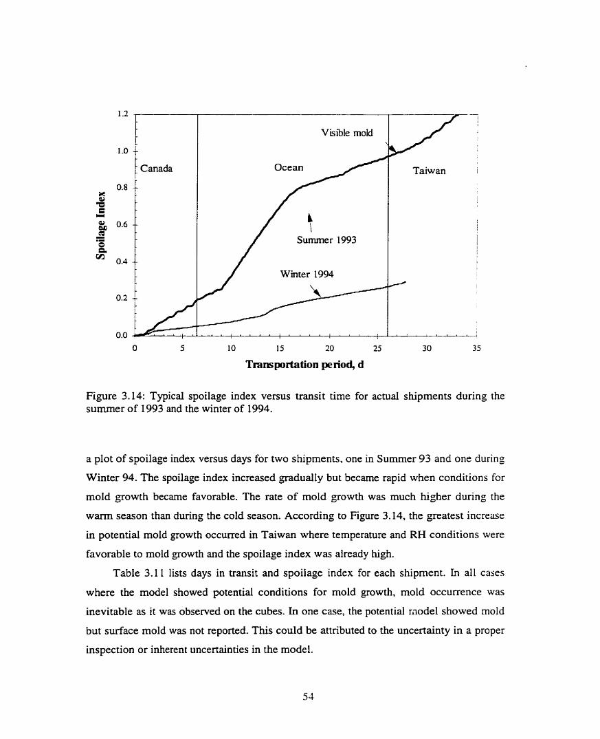
/ Canada Ocean
Sumrner 1993
Wmter 1994
Visible mold
Taiwan i
Figure 3.14: Typical spoilage index versus transit time for actual shipments during the s u m e r of 1993 and the winter of 1994.
a plot of spoilage index versus days for two shipments, one in Surnrner 93 and one during
Winter 94. The spoilage index increased gradually but became rapid when conditions for
mold growth became favorable. The rate of mold growth was much higher during the
warm season than during the cold season. According to Figure 3.14, the greatest increase
in potential mold growth occurred in Taiwan where temperature and RH conditions were
favorable to moId growth and the spoilage index was already high.
Table 3.1 1 lists days in transit and spoilage index for each shipment. In a11 cases
where the model showed potential conditions for mold growth, mold occurrence was
inevitable as it was observed on the cubes. In one case, the potential mode1 showed mold
but surface mold was not reported. This could be attributed to the uncertainty in a proper
inspection or inherent uncertainties in the model.

Table 3.11: Days in transit and spoilage index (SI) at stages of shipment.
Container Season Visual Loading Canada Ocean Taiwan
Number Inspection SI* Days SI Days SI Days SI
1.1 Sp 93 good - - - - - - - 1.2 Sp 93 good O 8 0.13 18 0.62 6 0.76
1.3 Sp93 good O 8 0.01 18 0.02 7 0.03
1.4 Sp 93 good O 8 0.12 18 0.47 7 0.55 - - - - - - -- -- -
2.1 Su 93 moldy - - - - - - - 2.2 Su 93 moldy - - - - - - - 2.3 Su 93 moldy O 7 0.20 20 LOO* 13 1-20"
2-4 Su 93 moldy - - - - - - -
3.1 Fa 93 good O 8 0.28 18 0.66 10 0.76
3.2 Fa 93 good - - - - - - -
3-3 Fa93 good - - - - - - -
3.4 Fa93 good O 8 0.18 18 0.44 10 0.52
4.1 Wi 94 good O 6 0.08 19 0.49 3 0.55
4.4 Wi 94 good O 6 0.05 19 0.26 3 0.29
5.1 Su 94 good O 8 0.15 12 0.52 26 0.84
5.2 Su94 good O 8 0.10 12 0.24 34 I.68*
5.3 Su 94 moldy O 8 0.14 12 0.30 - -
5.4 Su 94 moidy O 8 0.11 12 0.31 42 2.49*
'Sp' spring 'SU' summer 'Fa' fa11 'Wi' winter '*' SI2 1 mold growth has occurred '-' data not available

CHAPTER FOUR
THERMAL CHARACTRISTICS OF CONTAINERIZED
ALFALFA CUBES
4.1 Introduction
Containerïzed bulk cubes undergo extreme temperature variations during transport
from Canada to overseas destinations. These temperature variations were recorded during
actual transport. Appendix B presents these data. In this chapter the thermal environment
and heat transfer within the cube container will be presented rnathematically. The mode1
will be used to investigate the methods of preventing cube shipments from large
variations in temperature.
4.2 Mode1 Development
There have been severai studies conducted to predict the temperature distribution of
cereai grains in storage bins. The models developed were either based on conduction or
convection heat transfer equation or a combination of both. Yaciuk et al. (1975) showed
that the effects of natural convection on temperature distribution in stored grain is
minimal and the thermal environment in a free standing grain bin c m be modeled with
the conduction equation done. Similarly, Smith and Sokhansanj (1989) reported that the
temperature distribution in a bin containing srnall cereal grain like wheat is mainly
dorninated by conduction. However, for large particles like potatoes the effect of
convection was important. The average temperature of the stored material is not very
much affected by respiration and the slow moisture transfer occumng during storage.
Beukema et al. (1983) also developed a temperature distribution mode1 for a porous
medium in a closed container with natural convection and conduction. They reported that
natural convection accelerated the cooling of the material and the predicted average
temperatures were lower than with pure conduction. With natural convection, the location
of maximum temperature shifted from the center of container upwards. A two-
dimensional time-dependent model had been developed for grain by Nguyen (1987). The
model used both convection and conduction heat transfer. Using of Stream Iines,
isothems, velocity vectors and grain moisture content, he was able to show that the
circulation of air in the grain bulk was a result of strong convection flows in the
headspace. He concluded that the effect of naturai convection on the temperature
distribution is significant for small grains stored in the containers with headspace.
Lo et al. (1975) used a decoupled heat and mass transfer model to study the
temperature change within a closed cylindrical storage bin due to climatic temperature
variations. They found that the grain moisture content changed due to changes in
temperature. Lo et al. (1975) tested the grain storage conditions by comparing
temperature and moisture content with "safe critena" as were suggested by Burges and
Burrel (1964). They concluded that the risk of damage to grain was highly dependent
upon the initial temperature and moisture content of the grain. The darnage could be
reduced by having good insulation of the storage structure provided the initiai conditions
of grain were favorable. Their analysis showed that the grain was most susceptible to
damage in locations near the surface of the grain where the standard deviation of
temperature was the largest.
In this study, shipping container with cubes are exposed to direct sunshine dunng
transit. The Sun heats up the roof resulting in an increased radiation between surface of
cube and the ceiling of the container. The data in Appendix B shows that for the majority
of the cube shipments, the headspace temperature was greater than the temperature of the
cubes and the ceiling temperature in many cases increased to more than 40°C during the
day . Figure 4.1 shows a schematic diagram of alfalfa cubes and the prevailing
temperature and heat fluxes within the container. The typical container dimensions are
2.3 m high, 2.3 m wide, and 12.2 m long. A mobile conveyor is used to load cubes into
the container to fil1 the container not more than 75% (1.7 m high) of the container

Figure 4.1: Heat transfer inside aifalfa cube container. q, is radiation heat transfer between container ceiling and cube surface. qh is the convective heat transfer between the headspace and cube surface. Tc, Ta, Ts (input data), and Tp are ceiling, headspace, surface and pile temperature, respectively. Drawing is not to scale.
volume.
The container with its contents is a three dimensional system and as such has to be
modeled and analyzed. In this study a one dimensional case will be developed. Since the
container is 12.2 m by length and 2.3 m in wide, the edge effect on the two ends of the
container c m be neglected. The container is 2.3 wide and thus neglecting the edge effect
on these two sides of container could effect the temperature and moisture profiles within
the cube pile. Zn this present anaiysis however, we assume that temperature and moisture
gradient are only in vertical direction. This simplification could also be supported by the
fact that the largest temperature gradients are between the roof and the cube surface. It is
also expected that heat and mass flow will take place primarily between the top cube and
few centimeters into the cube pile. To wnte the goveming equations the following
assumptions are made for the boundary conditions:
(a) The mechanism of heat transfer from and to the cubes is by radiation (q,) and
convection (qh) between headspace and the top boundary of cubes.

(b) The rate of moisture transfer within the cube pile and between air and cubes is
slower than the rate of heat transfer. The thermal diffusivity (a = Wpc) for the
bulk cube is about 4x10-~ m2/s whereas the rnoisture diffusivity of cubes is
8x10"~ m% (Fasina. 1994).
A heat balance through a small volume of cube within the pile is written as:
where p b and cb are density and heat capacity of bulk cube. respectively. Equation 4.1 can
be written for a point as:
where
where p, and c, are density and specific heat of air, u is intergranular air velocity and kb is
buik thermal conductivity. The air movement in this analysis is due to natural convection
dT only. upac,T represents the bulk flow of heat caused by air movement. The term kb-
dx
represents the conduction heat transfer. Substitution Eqs. 4.3 into 4.2 results in:
Equation 4.4 descnbes the heat flow within the cube pile. At the boundary, three
situations can be specified:

1) Surface temperature of the cube is known:
2) The heat transfer is by convection oniy:
3) The heat transfer is by a combination of convection and radiation. The potential for
radiation is the ceiling (roof) temperature and the cube surface temperature.
aT - k, axI = MT, - T, ) + ea[(T, + 273).' - (T, + 273)']
where Ts is the cube surface temperature in OC, T, is inside the container air temperature
in OC, Tc is the ceiling temperature in OC , E is the net emissivity or absorptivity of the
alfalfa cube and the ceiling surfaces, (3 is the Stefan-Boltzman constant, 5.670 x 1 0 - ~
W . m-' . K4.
4.3 Numerical Solution
The governing heat transfer Eq. 4.4 is recast into a finite difference equation by
employing fonvard difference approximations for time derivatives and central difference
approximations for the spatial derivative (FTCS) (Riggs, 1988):
where i is space and n is time indices. The constants D and C are defined as:

kb where a, = - P A is bulk thermal diffusivity and y = - is the ratio of thermal
f'bCb PbCb
capacity of air to cube. The following stability criteria control the size of At and Ax:
Re, = 7 4
where Re, is cailed the ce11 Reynold's number (Riggs 1988).
The initiai condition for this probIem was T(x, O)= Ti. The two boundary conditions
were the one at x = O which was one of the conditions of 4.5, 4.6 or 4.7 and the second
one which was the common boundary condition at x = H:
H is the depth of the bulk in the container. The fully backward one-side finite-difference
approach is used for boundary condition 4.13 (Riggs, 1988):
For the convection boundary condition, Eq. 4.6 at the top of the cube, the fonvard
two point one-side finite difference approach is applied:
For the convection and radiation boundary condition, Eq. 4.7, the following
numerical expansion is used:
The method of bisection was used to calculate the boundary surface ternperature.
The finite difference equations were coded in FORTRAN. To estimate u and E. the
sum of squares of residuals (the difference between calculated temperature and
experimental temperature), SSR, was calculated. The optimum u and E were the values
when SSR was at its minimum:
A
where t is time, Tp and T, are measurernent and calculated temperatures at 60 cm below
the surface (Fig. 4.1).
4.3.1 Evaluation of constants
For numerical calculations, the following constant values were needed to be
specified: specific heat of the air in bulk cube c,=1007 J . kg-' . K-' (incropera and Dewitt.
1990). cube bulk density pb= 475 kg/m3 (Sokhansanj et al.. 1993). The following
equations were used to calculate k b and cb:

where f = 0.45 is the cube porosity (Sokhansanj et al., 1993), cc= 1490 J . kg-' . K-1 is the
cube specific heat (Fasina, 1994), ka= 0.41 W. m-' . K-' is the air thermal conductivity
(Incropera and Dewitt, 1990), and k, = 0.41 W. m-' . K" is the cube thermal conductivity
(Khoshtaghaza et al., 1995).
4.3.2 Convective heat transfer coefficient
The convective heat transfer coefficient was estimated h m empirical correlations
developed for rectangular enclosures (Incropera and Dewitt, 1990). When the cube
surface temperature (T,) was higher than the ceiling temperature (T,), the heat transfer
coefficient was calculated from the correlation proposed by Globe and Dropkin (1959) as
given by Incropera and Dewitt (1990):
where RaL is the Rayleigh number, w is the width of the container in m, g is gravitational
acceleration 9.8 1 m/s2, P is the expansion coefficient of air (lm), and a and v are the air
thermal diffusivity in m2/s and kinematic viscosity in m2/s, respectively. Pr is the prandl
number (v la) . Al1 of the properties were evaluated at the average temperature,
T = (Tc + T,) 1 2 . The following correlations in the range of 200K 5 TI 350K were
developed frorn the data in Incropera and Dewitt (1990) for dry air:

When Tc > Ts, the heat transfer fro~n the ceiling to the cube surface is exclusively by
k a conduction (NuL = 1) and thus the convection coefficient can be estimated from h = - W
(hcropera and Dewitt, 1990).
4.3.3 Evaluation of the numerical solution
The numerical solution was checked against an analytical solution available for a
simple geometry. The heat equation for transient condition in a semi-infinite solid at
constant surface temperature boundary condition is given by (Incropera and Dewitt,
1990):
where erf is the Gaussian error function. T, and T, are the initial and surface temperature
in OC, and t is time in S. The following problem was solved by the analytical method (Eq.
4.27) and the numericd method (Eq. 4.8) with a constant surface temperature boundary
condition. This problem is taken from Incropera and Dewitt (1990 page 262):
What minimum burial depth (X,) would you recomrnended to avoid
freezing of the water main (Fig. 4.2) under conditions for which soil,
initiaily at a uniform temperature of 20°C. is subjected to a constant
surface temperature of - 15°C for 60 days?
Table 4.1 shows the temperature of the soi1 at different depths using Eqs. 4.27 and 4.8
and the sum of squares of the difference between these two equations. X, was found to
be at 68 cm for the analytical solution and 71 cm for the numerical solution. Table 4.1
shows that the numerical method proposed in this chapter caiculated the soil temperature
to within 0S0C of the analytical solution.

Soil
Ti = 20°C
I Water main
Figure 4.2: Example problem for a semi-infinite solution of heat equations. This problem was used to compare the numencal solution with the analytical solution.
Table 4.1: Soil temperature, O C , at different depth by analytical (Eq. 5.27) and numerical methods (Eq. 5.8).
Methods Depth of soil, cm O 10 20 40 68 71
Analytical - 15 - 12.6 - 10.3 -5.7 O 0.7
SSR O 0.30 0.03 O. 12 O. 12 0.43
SSR = Sum of square of residuals

4.4 Results and Discussion
Equation 4.4 was solved for three boundary conditions using the experimental data
obtained from the tests outlined in Appendix B as input. The data were selected from the
containers located on deck-starboard side during sumrner and winter (Containers
MOLU2086380 and GSTU763369 1 in Table B. 1 ). Recorded temperatures on the surface
of the cubes and those at 60 cm deep in the pile were compared to the temperature values
cornputed for these locations. Table 4.2 lists the a b and u values estimated for the case
where the surface temperature was specified for January 1994 data. ab = 4.08 x 10'%nm'/s
was calculated directly from known values of kb, p b and cb. The resulting value was
multiplied by factors 10, 20, or 30 and likewise the vales of u were set as 2 x IO-^. 2 x 10-~, 2 x IO-', or 2 x 10-~ rnls. The sum of square of residuals (SSR) were cornputed
for each combination of these parameter. Table 4.2 shows that the minimum SSR was at
ab = 8.16 x 10.' m2/s and u = 2 x 1 0 - ~ m/s.
Similar procedures were used to calculate temperatures at the surface and
temperature at 60 cm below surface for the case of convective boundary condition. Table
4.3 lists the SSR values for a b and u. For these tests the heat transfer coefficient (h) was
calculated from Eq 4.22. The least SSR value of 38 10 was obtained when a b = 4.08 x 10"
rn2/s, u = 2 x IO-^ mis.
Table 4.4 gives the optimum values of ab, u, and E when the combined convection
and radiation boundary condition was applied. The least SSR values listed in the Irist
colurnn of Table 4.4 indicates the values of ab= 4.08 x IO-' rn2/s , u = 2 x 1 0 - ~ m/s. and
E = 0.5 are optimum values.
Table 4.5 summarizes the values for optimum conditions for the January 1994
shipment. The boundary condition lx=, = Ts (constant surface temperature) resulted in
the lowest SSR. The convection boundary condition did not yield minimum SSR
indicating that the heat transfer to cube was not by convection only. A combined radiation
and convection model provided a better solution than a convection model alone. For al1
three conditions u= 2 x 1ov6 d s was the optimum air speed. Figures 4.3 to 4.7 plot

Table 4.2: Parameter estimation for given surface temperature as boundary condition (Eq. 4.5) for January 1994 shipment.
ab, m2/s u, m/s 60 cm SSR
4.08~ 10-~ 2~ 1om5 10439
4 . 0 8 ~ 1 o ' ~ 2x 1 Oa 456 1
4.08x10-~ 2x 1 O“ 36212
4 . 0 8 ~ 1 O-' 2x 1 44306
4 . 0 8 ~ 1 O-' 2x 1 1957
8.16x10-' 2x 1 o - ~ 1591
1 .22x 1 o4 2x 1 o 6 1657
CQ, = bulk cube thermal diffusivity u = intergranular air velocity SSR = Sum of square of residuals
Table 4.3: Parameter estimation for convective boundary condition (Eq. 4.6) for the January 1994 shipment.
ab, m2/s u, m/s Surface SSR- 60 cm SSR
ab = bulk cube thermal diffusivity u = intergranular air velocity SSR = Surn of square of residuals

Table 4.4: Parameter estimation for convective and radiative boundary condition (Eq. 4.7) for the January 1994 shipment.
m, mL/s u, d s E Surface SSR 60 cm SSR
ab = bulk cube thermal diffusivity u = intergranular air velocity E = emissivity SSR = Sum of square of residuals
Table 4.5: Optimum values for the boundary conditions for the January 1994 shipment.
Boundary conditions ab, m2/s u, mis E 60 cm SSR 60 cm ATD, OC
a) Convection+ 4.08~ IO-^ 2x 1 O" 0.5 2213 1.3
Radiaton
b) Convection 4 .08~10-~ 2x10-~ - 2333 2.0
c) Constant Surface 8.16x10-' 2x10-~ - 1591 2.4
Temperature
ab = bulk cube thermal diffusivity u = intergranuhr air velocity E = emissivity SSR = Sum of square of residuals ATD = Average temperature difference

/ - Recorded 60 cm - Cornputrd 60 cm /
Min SSR= 1591
u= 2x10-~ d s -
Figure 4.3: Recorded and computed temperatures at 60 cm below the surface of the cube with constant surface temperature condition for the January 1994 shipment.
1 - Recorded 60 cm - Cornputcd 60 cm / 20
Min SSR=3810
u = 2x10-~ ds
ab = 4.08~1 O" rn2/s
Figure 4.4: Recorded and computed temperatures at 60 cm below the surface of cube with convection boundary condition for the January 1994 shipment.

I- Recorded air - Recorded surface. - Computed surface /
Min SSR=3810 u= 2 ~ 1 0 ~ ds
IB = 4.08x10-' m2/s
O 5 10 15 20 25 30
Trans porta tion pe riod, d
Figure 4.5: Recorded and computed surface tempenture of cube with convection boundary condition for the January 1994 shipment.
1 - Recorded 60 cm - Comp uted 60 cm ]
1 Min SSR=2213 1
Figure 4.6: Recorded and computed temperatures at 60 cm below the surface of cube with convection and radiation boundary condition for the January 1993 shipment.

- - -
Recorded air - Recorded surface - Computed surface 35 I
I
Figure 4.7: Recorded and computed surface temperatures of cube with convection and radiation boundary condition for the January 1994 shipment.
recorded and computed temperatures of the surface and 60 cm into the cube pile for each
boundary condition. In most of the cases, the average difference between the measured
and calculated temperatures was less than 2°C for each location in the cube pile.
Tables 4.3 and 4.4 show that the SSR of the surface temperature was almost
constant. On the other hand the SSR for temperature distribution 60 cm below the surface
changed substantially, from one set of parameter estimates (ab, u, E) to another. As such.
it would be more appropriate to estimate the parameters using the temperature
distribution 60 c m below the surface. Ideally, the recorded air temperature should be
close to the recorded surface temperature. But Figures 4.5 and 4.7 show an average
difference of 2S°C between recorded air and surface temperature. Since the recorded
surface temperature did not fluctuate like the recorded air temperature, it is likeIy the
sensor measuring the surface temperature was covered with cubes. Also the measured

surface temperature may not have reflected the actual condition, because the cubes
changed profile during transit.
Because of the difficulty and uncertainty in surface temperature measurement, the
surface temperature boundary condition is not recomrnended for simulation. Thus, for
solving Eq. 4.4, the proper boundary condition is a combined convection and radiation
boundary condition (Table 4.3, which is based on the ceiling and headspace air
temperatures. Also the lowest average difference in temperatures between the recorded
and computed conditions at 60 cm was 1.3"C for the convection and radiation condition
(Table 4.5).
Table 4.4 shows that reducing the emissivity value from 0.7 to 0.3 caused a little
reduction in the SSR for the 60 cm temperature from 4388 to 4355. Also by changing air
speed from 2 x 10 '~ to 2 x IO-* and 2 x 10" mls, the 60 cm SSR increased from 4368 to
287 19 and 34496, respectively. The SSR at 60 cm increased by about 50% (22 13 to 4272)
when the thermal diffusivity (a = 4.08 x 10-') was multiplied by 3. Thus. for the
combined convection and radiation, the temperature at 60 cm below the surface was not
sensitive to ernissivity but had a high sensitivity to air speed and thermal diffusivity.
The results of calculated values of Q, U, and E for July 1993 data are listed in
Tables 4.6 to 4.9 and Figures 4.8 to 4.12. The trend of data shown in the graph and tables
are sirnilar to January 1994 data.

Table 4.6: Parameters estimated for the given surface temperature as b o u n d q condition (Eq. 4.5) for the July 1993 shipment.
--
ab, m2/s U, m/s 60 cm SSR 4 . 0 8 ~ 10 -~ 2x 1 o - ~ 9 12 4 . 0 8 ~ 1 O-' 8x 1 o - ~ 703 4 . 0 8 ~ 10 -~ 5x 1 569 4 . 0 8 ~ 3x 10 -~ 607 4 . 0 8 ~ 1 2x 1 1683 1 22x 1 2x 1 389 1 . 2 2 ~ 1 3x 1 0 - ~ 34 1
1 . 2 2 ~ 1 5x 1 442 1 . 2 2 ~ 1 O 926
ab = bulk cube thermal diffusivity u = intergranular air veIocity SSR = Sum of square of residuals
Table 4.7: Parameters estimated for convective boundary condition (Eq. 3.6) for the July 1993 shipment.
m. m2/s u, m/s Surface SSR 60 cm SSR
- - - - - - - -
a b = bulk cube thermal diffusivity u = intergranular air velocity SSR = Sum of square of residuals

Table 4.8: Parameters estimated for the combined convective and radiative boundary condition (Eq. 4.7) for the July 1993 shipment.
a, mZ/s u, m / s E Surface SSR 60 cm SSR
- - -
ab = bulk cube thermal diffusivity u = intergranular air velocity E = ernissivity SSR = Surn of square of residuals
Table 4.9: Optimum values for the specified boundary conditions for the July 1993 shipment.
Boundary conditions ab, m2/s u. rnfs E 60 cmSSR 6 0 c m x ~ . OC
a) Convection+ 4.08x10-~ 2x10*~ 0.5 545 1.6 Radiation
b) Convection 1 .22~ 1 2x 1 o - ~ - 1000 2.6 c) Constant 1.22x10⁶ 3x10-~ - 34 1 1.1
Surface Temp. ab = bulk cube thermal diffusivity u = intergranular air velocity E = ernissivity SSR = Sum of square of residuals ATD = Average temperature difference

30 - -
Y 25 --
3 r)
Cs L
Min SSR= 341 15 -
u =3x 1 0 - ~ d s -6 '
CL^ = 1 .Ex10 mb/s 1 10 -
O 5 1 O 15 20 25 30 35
Tmnspottation period, d
Figure 4.8: Recorded and computed temperatures at 60 cm below the surface of cube with constant surface temperature condition for the July 1993 shipment.
1 - Recorded 60 cm - Cornpuied 60 m. /
Min SSR= IOOO
u = 2x10-~ d s
O 5 10 15 20 25 30 35
Trans portation period, d
Figure 4.9: Recorded and computed temperatures at 60 c m below the surface of cube with convection boundary condition for the JuIy 1993 shipment.

1 - Recorded air - Recordcd sudacc - Cornputeci surface 1
O 5 10 15 20 25 30 35
Transportation period, d
Figure 4.10: Recorded and computed surface temperatures of cube with the convective boundary condition for the July 1993 shipment.
- Recorded 60 cm - Compuied 60 cm 1 1
Min SSR=545
= ~ X I O ~ ds E = 0.5
O 5 1 O 15 20 25 30 35
Transportation period, d
Figure 4.1 1: Recorded and computed temperatures at 60 cm below the surface of cube with convection and radiation boundary condition for the July 1993 shipment.

/- Recorded air - Recorded surface - Cornputed surface i 1
50
Figure 4.12: Recorded and cornputed surface temperature of cube with the combined convection and radiation boundary condition for the JuIy 1993 shipment.

CHAPTER FIVE
MOISTUR-33 BALANCE
5.1 Introduction
The analyzed data of containerized bulk cubes showed that the humidity ratio in the
headspace increased during shipments from Canada to Taiwan (Appendix B). The
moistwe content of the cubes on the surface of the load also increased. The moisture
content inside the pile did not change. In this chapter, moisture transfer within the cube
pile and between cubes and the headspace is modelled mathematically. The humidity
ratio and moisture contents of the cubes inside the container are calculated. The computed
moisture balance is compared to the recorded humidity ratio in the headspace.
5.2 Mode1 Development
For the development of a moisture balance, it is assumed that the container is
completely sealed. Moisture transfer inside the cube pile in the container is due to vapor
diffusion. The result of thermal modeling inside the cube container showed that the flow
of air within the bulk of cubes was very small, on the order of 2 x 1 0 ' ~ m/s. Since
expenmental data for shipments showed that the cube moisture at 60 cm below the
surface did not change appreciably. It was assumed for sirnplicity that convective mûss
transfer within the pile was not a major factor. Thorpe (1982) also did not include this in
his models of grain storage systems. An equation analogous to equation 4.1 is written for
moisture balance within the cube pile:

where m is moisture flow in kg. s-' . m-'. C is moisture concentration in kg/m3 and t is
time in S. Equation 5.1 is written for a point as:
Using Fick's diffusion Iaw, the moisture flow within the bulk by diffusion only is
descnbed by:
where Dm is a moisture diffusion in m2/s. Substituting Eq. 5.3 in 5.2 results in:
Equation 5.4 describes moisture concentration within the bulk. The initial condition for
the problem is:
For boundary conditions, it is assumed that the cube pile is sufficiently deep so the
moisture content of the bottom layer remain constant. This assumption is justified by

experimentai data on the cube shipments whereas the moisture content of cubes rit 60 cm
deep did not show significant changes dunng the entire trip.
The second boundary condition on the surface of the cube pile at x = O is:
where ho is the mass transfer coefficient (rn/s) between the surface of the bulk and the air
in the headspace above the cubes. Equation 5.7 States that the moisture concentration C
within the bulk is bdanced by the moisture concentration in the headspace which is Ca.
Pixton and Griffiths (197 1) used grain moisture concentration gradients to describe
the diffusion process of moisture through a grain bulk (Eq. 5.4). They pointed out that the
isothemal diffusion of moisture through stored wheat is a very slow process. Thorpe
(1981) studied moisture diffusion through bulk grain and considered interstitial water
vapor pressure as the fundamental driving force. Thorpe (1982), using the ideal gas law,
recast Eq. 5.4 into the fonn of Eq. 5.8:
where P, is the partial pressure of interstitial water vapor in Pa, D, is the diffusion
coefficient of water vapor in air in m2/s, R, is the universal gas constant for water vapor
(46 1-52 J . kg" . K I ) , T is temperature in OC, E, is the porosity of bulk product. and y! is
an obstructive factor. The obstructive factor lumps the effects of tortuosity of the bulk and
the constrictive nature of the diffusion channek due to variations in the cross-sections of
the diffusion path.

Thorpe (1982) did not explain why the ideai gas law was applied only to the left
hand side of Eq. 5.4 while the nght hand transit term was kept intact. It appears that this
is a convenient step in solving this complicated problem. The nght hand side of Eq. 5.8
represents the gradient vapour pressure in the voids: the left hand side of the equation
describes the transient moisture changes in the solid.
Van Brakel and Heertjes (1974) reported the experimental values of the obstructive
factor for randornly packed granular media to be in the range of 0.50-0.60, and 0.55 was
selected for bulk alfalfa cube. Sokhansanj et ai. (1993) found a value of 0.45 for the
porosity of regular size alfalfa cube samples at 12% moisture content.
It is assumed that there is always equilibrium of rnoisture between the cube and air.
The partial pressure of water vapor in air can be found from its relative humidity and
saturation vapor pressure of water, P,:
where rh is the relative hurnidity (fraction) and P, is the saturation vapor pressure (Pa)
that can be found from psychometrîc properties (ASAE, 1994d). The relative humidity
inside a bulk cube c m be calculated from equilibrium moisture relations. In this study.
the Chung-Pfost equation for an alfalfa cube as given by Fasina and Sokhansanj (1993)
was used:
where M, is the moisture content in dry basis, fraction; a = 276.774, b = 35.856, and
c = 19.1 15 . The concentration of water in bulk cube was found from:

where p, is the dry bulk density of alfalfa cubes in kg/m3 which is assumed constant at
475 kg/m3 (Sokhansanj et al., 1993). Differentiating Eq. 5.1 1 with respect to time,
assuming no change in dry bulk density and using the chah rule, we get:
Finally Eq. 5.8 is written in the final form:
a p v When - is found from differentiating Pv with respect to Me in Eqs. 5.9 and 5. IO., aMe
equation 5.14 results in:
Equation 5.14 can be expressed as:
where p is a function of T and M, through the relationship:
The initiai and boundary conditions were used to solve Eq. 5.16:
The Lewis's reIation can be used to estimate the value of hD (Holman, 1990):
where h is the convection heat transfer coefficient in W . rn-'. K-'. Based on calculation
from Eq. 4.22, the value of 10 W. m-'. K-' was used for h. p, is the dençity of the air in
kg/m3, and c, is the specific heat of the air in J . kg" . K1, p,= 1.16 kg/rn3 and c, = 1007
J . kg-' . Ki. Holman (1990) reported the following empincai relationships for Dv,
diffusion of water vapor into air:
where T is in OC and D, is in m2/s.

5.3 Numerical Solution
A finite difference procedure similar to that used for heat transfer in Chapter four
was used to solve Eq. 5.16. The initial value for P, was calculated using the initial
temperature and relative humidity inside the buIk cube. Initially, aH P,'s including the P,,
of the headspace were set equal to the initial vapor pressures. The nodal points for the
mass transfer equations are depicted in Figure 5.1. Node O is in the headspace, node 1 is
on the cube surface and nodes 2, 3, 4, ..... are within the cube pile. Node B is at the
bottom of cube pile. The following finite difference equation was applied for the nodes
(2,3,4,. . .) in the cube pile:
The equation for the node I at the surface is expressed as:
Initially, Pv, is set equal to P, . the vapor pressure of the air in the headspace. P, is not
known beyond time zero. The only information available assurning a sealed condition is
the headspace temperature. Thus the set of equations is indeterminate. Ln other words, the
number of unknown nodal values for P,'s is one more than the number of equations. To
solve this problem another equation was developed. A moisture balance between the cube
top layer and the air in the headspace yields:
where H is the headspace humidity ratio in kgkg, A is the surface area of the bulk cube
perpendicular to the flow of moisture in m'. p, is the density of dry air in kg/rn3 and V, is

Headspace
Alfalfa Cubes
Figure 5.1: Finite difference nodes for the numerical solution of rnoisture transfer within bulk cubes and between cubes and the headspace. Drawing is not to scale.
the volume of headspace
pressure using the ideal gas
P
in m3. Concentration of moisture can be related to vapor
law :
where Pv is the vapor pressure in the air, R, is the universal gas constant for water vapor
and TabS is the absolute air temperature. Since R, and Tabs were assumed constant over a
small increment dx and dt, Eq. 5.25 can be expressed in terms of Pv:
In finite difference form, Eq.5.27 is expressed as:

where L is the depth of the headspace in m. Vapor pressure of air was found from the
following equation (ASAE. 1994d):
At intervals. the cdculated PV1s were used to estimate the corresponding humidity
ratio of headspace and moisture contents within the bulk cube.
The forward time central space finite difference method (FTCS) was used to solve
the goveming Eq. 5.16. The finite difference equations were written in FORTRAN code
with a time step (At) of 2 min and a space step (Ax) of 0.003 m.
5.3 Results and Discussion
5.3.1 Headspace humidity ratio
Equation 5.16 was solved for typicd recorded data of containerized alfalfa cube
shipments for May 1993, July 1993, October 1993, January 1994, and June 1994
(Appendix B). Figures 5.2 to 5.6 plot the recorded and the computed humidity ratio of the
headspace inside the container. The recorded hurnidity ratio was cdculated from the
psychometric relations between the measured temperature and relative hurnidity in the
headspace. The cornputed humidity ratio was from the numencal solution of Eq. 5.16
using the recorded temperatures in the headspace and the recorded temperatures inside the
cube pile. This computed humidity ratio represents the condition where the container is
assumed completely sealed.
The recorded humidity ratio of air inside each container is summarized in Table B.5
(Appendix B). Figures 5.2 to 5.6 show that after the containers were loaded with the

t 1 -Recordrd - 1
Cornputcd 1
35 t Canada Ocean Taiwan
Figure 5.2: Humidity ratio inside the cube container calculated from the recorded temperature and RH and the simulated humidity calculated from Eq. 5.16 (computed at sealed condition) for the May 1993 shipment
Canada i 35 Ocean : Taiwan
Transporta tion pe rio& d
Figure 5.3: Humidity ratio inside the cube container caiculated from the recorded temperature and RH and the simulated hurnidity calculated from Eq. 5.16 (computed at sealed condition) for the July 1993 shipment

35 Canada Ocean Taiwan
Figure 5.4: Humidity ratio inside the cube container calculated from the recorded temperature and RH and the simulated humidity calculated from Eq. 5.16 (computed nt sealed condition) for the October 1993 shipment
. Canada : Ocean Taiwan
Figure 5.5: Humidity ratio inside the cube container calculated from the recorded temperature and RH and the simulated humidity calculated from Eq. 5.16 (computed at sealed condition) for the January 1994 shiprnent.

1 - actual - catukted /
Ocean Taiwan
Figure 5.6: Humidity ratio inside the cube container calculated frorn the recorded temperature and RH and the simulated hurnidity calculated from Eq. 5.16 (computed at sealed condition) for the June 1994 shipment.
cubes, the overail humidity ratio started to increase until the container was placed on the
vesse1 in Vancouver. The hurnidity decreased during ocean travel and again started to
increase by the time the container arrived at a port in Taiwan. At the tirne of unloading.
the hurnidity ratio increased to the highest level. For example, during the May 1993
shipment (Fig. 5.2), the hurnidity ratio in the space was about 6 g k g of air in the
container after the container was loaded with cubes. The absolute hurnidity increased to
about 10.8 g/kg in Canada. It decreased to about 7 g k g during the ocean and increased to
12.2 g k g in Taiwan, and finally to 21.9 g k g at the time of unloading.
The recorded headspace hurnidity fluctuated during shipment, specially in Canada
and Taiwan. The fluctuation was more significant during warmer months. This mny be
from the repetitive evaporation and condensation on the surface of cube pile. For
instance, during the July 1993 shipment (Fig. 5.3), the recorded humidity ratio in the
headspace fluctuated daily from 10 to 20 g/kg while the load was in transit in Canada.

The humidity ratio decreased to about 8 @kg on the ocean and then increased to 22 @kg
when the load anived in Taiwan. While in Taiwan, the humidity ratio showed diurnai
variations representing repetitive evaporation and condensation. On the other hand the
computed humidity ratio did not show large variations. It showed an increase from 8 g/kg
to about 14 g/kg during the entire time of travel (Fig. 5.3).
The results show the recorded overall humidity ratio was higher than the computed
hurnidity ratio. Most of the moisture accumulation happened during the warmer months
(Figs. 5.3 and 5.6) and once in Taiwan when a container waç waiting to be unloaded.
Also, based on the recorded data, the moisture content of the cube pile (especially the
middle of the pile) was almost constant during transport. It can be concluded that the
difference between the recorded and computed humidity ratio was due to the moisture
penetrating from outside into the headspace.
During Canada, the difference between the recorded humidity ratio and the
computed values increased to about 5 g/kg in July 1993 and 1.2 g/kg in January 1994.
Whereas, the difference decreased during ocean transport and the difference increased
when the container arrived in Taiwan (about 13 g k g in July 1993 and 4 g k g in January
1994). The large difference between the hurnidity ratio in sumrner compared to winter
indicates that the surnmer air has higher hurnidity ratio than the winter air. Hence the
fluctuations of headspace humidity ratio (Figs. 5.3 and 5.6) is more pronounced during
sumrner than winter because the shipping container was not completely sealed.
5.3.2 Interna1 moisture transfer
The moisture contents recorded for the containerized cube shipments consisted of
the initia! moisture contents of cube samples at the time of loading and the moisture
contents of sarnples at the time of unloading (Table B.4). These moisture contents were
measured on the samples that were sent from Alberta and from Taiwan to the University
of Saskatchewan in Saskatoon. The exact sampling and shipping rnethod was not known.
Therefore, it was difficult to know how representative the reported moisture contents
were.

The simulation model of the vapor pressure in Eq. 5.16 dong with the equilibrium
moisture content relation in Eq. 5.10 were used to compute the moisture content on the
surface and 10 cm inside the cube pile. The recorded headspace temperature and
computed headspace relative humidity were used. The equilibrium moisture content in
Eq. 5.10 assumes that the entire cube is at a uniform moisture content and is completely
in equilibrium with its surrounding.
Figures 5.7 to 5.10 plot the computed moisture contents for shipments in May 1993,
July 1993, October and January 1994, respectively. Each shipment represents a season.
For the May 1993 and July 1993 shipments, the moisture contents show an increase when
the product is on the ocean. The cubes dried as they approached their pon of destination
in Taiwan. For October 1993 and January 1994 shiprnents, it appears that most moisture
fluctuations occurred in Canada and once on the ocean, the moisture content did not
fluctuate as much.
The recorded headspace temperature and relative humidity were used in Eqs. 5.10
and 5.16 to caiculate the surface moisture content and this value was compared to the
simulated moisture contents. Figure 5.1 1 plots the moisture contents on the surface and a
at several depths. It is noted that the computed moisture contents were lower than the
recorded moisture contents because of the assumption of "no l e a k in the model. The
surface moisture contents show fluctuation in both recorded and model calculations. But
the moisture content fluctuation leveled off at greater depths in the cube pile.
Table 5.1 shows the recorded and computed final moisture content of the cubes on
the surface at the time of unloading in Taiwan. For the May 1993 and July 1993
shipments, the recorded final moisture was higher than the cornputed moisture content.
For the October 1993 and January 1994 shipments the recorded final moisture content
and the computed moisture content are not much different. It can be deduced from the
data that moisture penetration into the container from the outside rnight be more severe in
warmer months than in colder months.
The model shows that under specified boundary conditions and assumption (no air
exchange occurred between the inside of the container and the outside air) the humidity
ratio of the headspace air did not increase. Correspondingly, there \vas no increase in

Canada Taiwan
Transportation period, d
Figure 5.7: Computed moisture contents on the surface and 10 cm into the cube pile for the May 1993 shipment.
1 O 15 20 25 Transportation perioà, d
Figure 5.8: Computed moisture contents on the surface and 10 cm into the cube pile for the July 1993 shiprnent.

/ - surface - 10 cm
1 Canada
Ocean
Figure 5.9: Computed moisture contents on the surface and 10 cm into the cube piIe for the October 1993 shipment.
- surface - 10 cm i Canada : Ocean Taiwan
Figure 5.10: Computed moisture contents on the surface and the January 1994 shipment.
30 35
10 cm into the cube pile for

Occan Taiwan
15 20
Transportaion period, d
I *-- Rccordcd ai 5 cin
Rccordcd ni 15 ciii
Rccordcd ai 20 cm
I- Coinputed nt ihe suriricc
Figure 5.1 1 Recorded and computed rnoisture content of bulk cube nt different levels for the june 94 shipment.

Table 5.1 : Recorded initiai and final and the computed final moisture content (%. w.b.) of cubes on the surface at the time of unloading in Taiwan.
Time of Recorded Computed
shipment Initial Final Final
May 1993 13.0 11.7 7.0
July 1993 12.3 22.9 8.5
October 1993 - 11.2 11.1
January 1994 11.6 11.9 10.8
June 1994 - 14.5 8.9
'-' not available
moisture content of the cubes. This suggests that perhaps there had been a leakage in the
container and some air exchange must have taken place. Since the mass of air in the
container is small as compared to the mass of products, the humidity ratio in the air is
sensitive to the changes in the cube moisture content.
It was also assumed that moisture content of the cube at the time of loading was
uniform through the pile. This assumption may not be valid as experience has shown that
the moisture content of cubes rnight Vary considerably, Le. 2 2% w.b. The accumulation
of moisture in the air and on the cube surface could also corne from successive
evaporation-condensation cycles that could have taken place inside the container. The
evidence also points to the fact that there is more moisture accumulation during warmrr
months when temperature variations are extreme, than colder months.
Considering al1 the above elements, it is concluded that there rnight have been some
degree of air exchange between the container headspace and the outside air. Consequently
the assumption of no air exchanpe used in the thermal mode1 (Chapter 4) could be
invalid. Nevertheless, the effect of air exchange on the thermal mode1 is difficult to asses
because data on ambient air condition during transport was not recorded.

CHAPTER SIX
CONCLUSIONS AND FUTURE WORK
6.1 Conclusions
This study focused on the effect of ambient conditions on the quality of alfalfa
cubes during their shipment from Canada to overseas. The containerized cubes were
exposed to extreme variations in temperature and humidity during transport. The data
obtained from commercial shipping showed the cubes absorbed moisture and sometimes
became moldy.
The research consisted of a laboratory experiment to study and develop a time-
dependent functional relationship between alfalfa cube quality and ambient temperature
and relative humidity. The heat and moisture transfers within the cube pile in a container
were modelled mathematically. The mathematical mode1 was used to identiw important
ambient factors to be monitored during shippings.
The following conclusions can be drawn:
1) The storage stability of alfaifa cubes is sirnilar to other agricukural products:
they can be kept safe at low temperature and humidity. Particularly, this research
showed that maintaining temperatures and relative humidity in the container
below 16°C and 70% RH extends the shelf life of the cubes to at least 90 days
(maximum number of days tested in this work). Therefore, in shipping cubes,
temperature and relative humidity should not exceed the aforementioned values.
2) Equations were developed to describe the quality of alfalfa cubes. The
independent variables are temperature and relative humidity of the environment.
The dependent variables are the important alfalfa quality factors.

a) the number of days that the cubes are mold free:
where d is number of days before visible mold is detected on the sample. k l
is a function of constant temperature and relative hurnidity (Table 6.1).
b) change in the green colour of cubes:
where a is the instantaneous colour and ai is the initial colour coordinate 'a',
k2 is given in Table 6.1 and t is time in days.
C) change in hardness:
where H and Hi are instantaneous and initial cube hardness (kN), k3 and IQ
are given in Table 6.1 and t is tirne in days.
w here
ki = ai + bi T + ci RH
Therefore, the quality models can be used to predict the cube quality during
storage or transit, provided that an online record of temperatures and humidities
is available.

Table 6.1: Constants a, b, and c and their estimates of standard errors (in parenthesis).
Constants a b c
k3 -0.142 0.00003 0.0028 (0.0 13) (0.00020) (0.0002)
k-4 4.132 0.004 0.03 1 (O. 13 1) (0.002) (0.002)
Table 6.2: Critical conditions and number of days before visible mold during the storage.
Temperature, RH, %
OC 60 65 70 75 80 85
'-' combination of temperature and RH was not attained 'N' mold did not appear '*' mold slightly

3) The appearance of visible mold on the cubes is the single most important factor
in downgrading and rejection of cubes. Table 6.2 summarized the critical
temperatures and relative humidities and nurnber of days before visible mold
was developed during the storage periods.
4) The calculated spoilage potentiai agreed with the observation of mold on the
cube. This mode1 can be used to predict the onset of mold growth dunng transit.
5) Based on the analysis of a one dimensional heat transfer of the containerized
cubes, cube temperature can be computed frorn the measurements of the
headspace temperature and the temperature of the container ceiling. Ceiling
temperature is important for the computation of radiative heat transfer to the
surface of the cubes.
6 ) The development of a one dimensional moisture transfer mode1 was carried out
with the assumption of no moisture exchange between the inside of the
container and the outside. The computed rnoisture contents were compared to
the recorded moisme contents obtained during commercial shippings. It is
shown that moisture increase in the cubes was a result of moisture penetration
into the container.
6.2 Suggestions for Future Research
The following are suggestions for further research:
Study of the feasibility to insulate, seal, andior ventilate the container filled with
alfalfa cubes to minimize temperature and moisture stratification within the
container.

Study methods of preventing direct contact between moist air and the cubes by
covering the cubes with a suitable barrier.
Conduct experiments in containers equipped with temperature and humidity
monitoring devices and a transmission signal to indicate in-transit conditions
within the container including the onset of visible mold.
Simulate of temperature and moisture distribution of cubes in containers
considering air exchange between the head space and the outside.
Extend the heat and mass transfer to two and three dimensional cases.
6.3 Practical Recommendation to Industry
Reduce the moisture content of cubes to 10%. The cube should be uniform in
moisture and d l are cooled and cured properly.
Seal or ventifate the container to minimize temperature and moisture
stratification on natural currents within the container. and to prevent the inflow
of additional moisture - especially from ocean air aboard ship.
Insulate the container wall especially the ceiling
Cover the cube surface with a shield to prevent direct contact between the cube
surface and wet condensate.
Place the container away from direct sunshine, rain, etc. A good location is
below the deck on the vessel. Placement of the containers below waterline
during sumrner is preferred.
Shorten the transit period especially rninimize time to unloading in Taiwan.
Equip each container with a temperature and humidity monitoring device and a
transmission signal to indicate the storage age of the cube. This device will give
the spoilage index for the cube. It sends a signal if cube has reach its storability
index of one.

AOAC. 1984. Official methods of analysis of the Association of Official Analytical
Chernists. Arlington, Virginia.
AS AE. 1994a. ASAE Standard S358.2: Moisture measurement-forages. In ASAE
Standards 1994,47 1. S t Joseph, MT: ASAE.
ASAE. 1994b. ASAE Standard S368.2: Compression Test of Food Material of
Convex Shape. In ASAE Standards 1994,472-475. St Joseph, MI: ASAE.
ASAE. 1994~ . ASAE Standard S269.4: Cubes, pellets, and crumbles-definitions and
methods for determining density, durability, and moisture content.. In ASAE
Standards 1994,44945 1. St Joseph, MI: AS AE.
ASAE. 1994d., 41th ed. ASAE Standard D271.2. Psychornetric data. Ln ASAE
Standards 1994,4446. S t Joseph, MI: AS AE..
Baufernfeind, J-C. 1981. Natural food colors. In Carotenoids as Colorants cuzd
Vitamin A Precursor, ed. by Baufernfeind, J-C. Academic press, New York,
m. Beukema, K.J., S. Bruin, and J. Schenk. 1983. Three-dimensional naturai convection
in a confined porous medium with interna1 heat generation. International
Journal of Heat and Mass Transfer 26:45 1-458.
Black, D., A. Rolow, and C.E. Nelson. 1990. Towards the development of an
analyticaI system for measuring hay cube colour quaiity. Antioxidant Research,
Kemin industries Inc. Des Moines, Iowa.
Bruhn, J.C. And J.C. Oliver. 1978. Effect of storage on tocopherol and carotene
concentrations in aifalfa hay. Journal ofDairy Science 61 :980-982.
Buckmaster, D.R., C.A. Rotz, and D.R. Mertens. 1989. A mode1 of alfalfa hay
storage. Transactions of the ASAE 32(1):30-36.

Burges, H.D., and N.J. Burrell. 1964. Cooling bulk grain in the British climate to
control storage insects and to improve keeping quaiity. Journal of the Science of
Food and Agriculture 15: 32-38.
Chaplin, R-V. and R.M. Tetiow. 1971. Storage of dned g ras waffers: moisture
relationships, safe storage periods and changes in durability. Jorimal of Stored
Products Research 7:171-180.
Christensen, D.A. 1990. Alfalfa utilization research. Special Report. Department of
Animal and Poultry Science, University of Saskatchewan, Saskatoon, Canada.
Christensen, C.M., and R.A. Meronuk. 1986. Quality maintenance in stored grain.
University of Minnesota Press. Minneapolis. MN.
Collins, M., W.H. Paulson, M.F. Finner, N.A. Jorgensen, C.R. Keuler. 1987.
Moisture and storage effects on dry matter and quality losses of alfalfa in round
bales. Transactions of the ASAE 30(4):9 13-9 17.
Dexter, S.T., W.H. Sheldon, and D.I. Waldron. 1947. Equiiibrium moisture content of
alfalfa hay. Agricultural Engineering 28(7): 295-296.
Fasina, 0.0. 1994. Cooling characteristics of alfalfa pellets. Unpublished Ph.D.
Thesis. University of Saskatchewan, Saskatoon, SK.
Fasina, 0.0. and S. Sokhansanj. 1992. Hygroscopic moisture absorption by alfalfa
cubes and pellets. Transacrion of the ASAE 35(5): 16 15- 16 17.
Fasina, 0.0. and S. Sokhansanj. 1993. Equilibriurn moisture relations and heat of
sorption of alfalfa pellets. Journal of Agricrtltriral Engineering Research 5 6 5 1 -
63.
Globe, S., and D. Dropkin. 1959. Natural convection heat transfer in liquids confined
between two horizontal plates. Journal of Heat Transfer 8 lC, 24.
Hall, C.W. 1980. Drying and Storage of Agricultrtral Crops. Westport, Connecticut:
AVI Publishing Company, Inc.
Headley, V.E. 1969. Equilibrium moisture content of some pelleted feeds and its
effects on pellet durability index. Transaction of the ASAE 12 ( 1):9- 12.

Hinds, R.H.JR. 1970. Containerized overseas shipping test with red grapefruit, carrots
and other vegetables. Texas Citrus and Vegetable Growers and Shippers
Yearbook.
Holman, T.P. 1990. Heat Transfer, Seventh Edition. Toronto, Ontario: Mc Graw Hill
Publishing Company, Inc.
Hoveland, C.S. 1980. Crop Quality Storage and Utilization. Madison, Wis. :
American Society of agronomy.
Hunter, T., and S. Sokhansanj. 199 1. Improving forage cube quality. AS AE paper No.
91-1 13. St. Joseph MI. American Society of Agricultural Engineers.
Lncropera. F. P. and D. P. Dewitt. 1990. Fundanlenfals of Hear and Mnss Transfer.
Third Edition. New York: John Wiley and Sons.
Jiang, S. and J-C. Jofnet. 1987. Finite element prediction of silage temperatures in
tower silos. Transaction of the ASAE 30(6): 1744- 1750.
Jiang, S., J.C. Jofnet and G.S. Mittal. 1986. Thermal properties of haylage.
Transactions of the ASAE 29(2):6O 1-602.
Khoshtaghaza, M.H., S. Sokhansanj, and R.J. Ford. 1995. Thermal diffusivity and
thermal conductivity of alfalfa cube. Cnnadian Agric~rltriral Engineering
37(4):32 1-325.
Lo, KM., C.S. Chen, J.T. Clayton, and D.D. Adrain. 1975. Simulation of temperature
and moisture changes in wheat storage due to weather variability. Joiuwzl of
AgrictclturaZ Engineering Research 20:47-53.
Muir, W.E. 1973. Temperature and moisture in grain storage. In: Grain Storage Part
of a System. Ed: Sinha, RN., and W.E. Muir. pp 49-70.
Muir, W.E. and R.N. Sinha. 1986. Theoretical rates of flow of air at near-ambient
conditions required to dry rapeseed. Canadian Agricultural Engineering
28(1):45-49.
Nguyen, T. V. 1987. Natural convection effects in stored grains-a simulation study.
Drying Technology S(4): 541 -560.
Orner, A., and H. Shushan. 1978. Transporting citms fruit in sealed containers.
Technical Report of Israeli Citrus Marketing Board.
Patil, R. T. and S. Sokhansanj, 1994. Colour and nutritional changes in green alfalfa
during high temperature drying. Agricultural and Food Engineering, of CIC
Saskatchewan Symposium, held at Park Town Hotel, 924 Spadina Cres. E.,
Saskatoon, October 28-29.
Patil, R. T., S. Soldiansanj, M.H. Khoshtaghaza, and L. Tabil. 1996. Compression
characteristics of alfalfa cubes. Canadian Agrictrltural Engineering 38(3): 195-
200.
Peieg, K. 1985. Produce Handling, Packaging and Distribution. Westport,
Connecticut: AVI Publishing Company. hc.
Pixton, S.W., and H,J. Griffiths. 1971. Diffusion of moisture through grain. Jo~wnnl
of Stored Product Research 7(3): 133- 152.
Pulkenin, D.A. 1975. Quality loss in storage of dehydrated alfalfa pellets as affected
by temperature. AIfalfa Dehydrators Research Laboratory Tisdale,
Saskatchewan.
Racz, V.J. 1994. Factors affecting forage quality and resultant processed forage
products. In Proceeding of the Technical Conference on "Recent Advances in
Alfalfa Harvesting, Processing and Handling ". Held at Delta Bessborough
Hotel, Saskatoon.
Riggs. J.B. 1988. An Introdrrction to Numerical Methods for Che~nictrl Erzgineers.
Lubock, Tex. Texas Technical University Press.
Rotz, C.A. and S.M. Abrams. 1987. Losses and quality changes dunng alfalfa hay
harvest and storage. Transactions of the ASAE 3 1(2):350-355.
Ryall, A.L., and W.J. Lipton. 1979. Handling, Transportation and Storage of Fniits
and Vegetables. Volume 1 . Westport, Connecticut: AVI Publishing Company,
Inc.
Ryall, A.L., and W .T. Pentzer. 1982. Handling, Transportation and Stornge of Fru irs
and Vegetables. Volume 2. Westport, Connecticut: AVI Publishing Company.
Inc.
SAS. 1986. SAS Users Guide: Statistics. Cary, NC: Statistical Analysis System
Institute Inc.

Schreiber, H., W. Muhlbauer, L. Wassermann and H. Kuppinger. 1981. influence of
drying on wheat quality-study of reaction kinetics. Zeitschrift fur Lebensmi t tè l -
Untersuchung und-Forschung, 173(3) 169- 175, Translated by Information
Services Department, National Institute of Agricultural Engineering, U. K.
Smith E.A. and S. Sokhansanj. 1989. Natural convection and temperature of stored
produce-a theoretical analysis. Canadian Agricdtltrirai Engineering 32: 9 1-97.
Snow, D., M. H.G. Crichton and N.C. Wright. 1934. Mold deterioration of feeding-
stuffs in relation to hurnidity of storage. The Annals of Applied Biology 3 1 : 102-
110.
Sokhansanj, S., M.H. Khoshtaghaza, W.J. Crerar, E.Z. Jan, A. McNeiI, and A.
Penner. 1996. Moisture migration in containerized alfalfa cubes during overseas
shipment. Department of Agricultural and Bioresource Engineering, University
of Saskatchewan, Saskatoon, SK.
Sokhansanj, S., W.G. Lang, and D.E. Lischynski. 1991. Low temperature drying of
wheat with supplement heat. Canadian Agricctltrrral Engineering 33:265-27 1.
Sokhansanj, S., W. Li, and 0.0. Fasina. 1993. Resistance of alfalfa cubes, pellets and
compressed herbage to airflow. Canadian Agricultural Engineering 35(3):207-
213.
Sokhansanj, S., R.T. Patil and G. Ahrnadnia. 1992. Physical characteristics of
commercial forage cubes and pellets. CSAE Paper No. 92-326. Saskatoon, Sk.
CSAE.
Sokhansanj, S., and H.C. Wood. 1991. Engineering aspects of forage processing for
pellets, cubes and dense bales. Advances in Feed Technology 5(1):6-24.
Tabil, L.G. And S. Sokhansanj. 1995. Effect of storage condition on the durability and
hardness of alfalfa pellets. ASAE Paper No. 95-6 114. St. Joseph MI. American
Society of Agricultural Engineers.
Thorpe, G.R. 198 1. Moisture diffusion through buIk grain. Jorirnal of Stored Prodrrct
Research 17:39-42.
Thorpe, G.R. 1982. Moisture diffusion through bulk grain subjected to a temperature
gradient. Journal of Stored Product Research 17: 39-42.

Van BrakeI. J. and M.P. Heertjes. 1974. Analysis of diffusion in macroporous media
in ternis o f a porosity, a tortuosity and a constnctivity factor. Inrernntional
Journal of Heaf and Mass Trans$er 17: 1093- 1 103.
Walton. P.D. 1983. Production and Management of Cultivated Forages. Reston
Virginia: Reston Publishing Company. Inc.
Yaciuk, G., W.E. Muir. and R.N. Sinha. 1975. A simulation Mode1 of temperature in
stored grain. Journal of Agricultural Engineering Research 20: 1-258.
Zink, F.J. 1935. Equilibnum moistures of some hay. Agricultural Engineering 16( 1 1 ):
45 1-452.
APPENDIX A
ALFALFA CUBES QUALITY CHARACTERISTICS DURING
66 AND 90 DAYS OF STORAGE

Table Al : CoIour. moisture, hardness, and density variations over rime during 66 days of
RH. %
L. a. b= colour coordinates value M= rnoisture content, w.b.. 5%
storage at Test
chamber
1.1
1.2
I
2.1
9 7 -."
r
3.1
3.2
4.1
4.2
p= density. ~ g / r n ~ shaded= molded sarnplc
16.
H= hardness. kN

Table A.2: Colour. moisture. hardness, and density variations over time during 66 days of storage at 24.0°C.
C
M= rnoisture content. w.b.. % shaded= molded sample
110
Test chambei
5.1
5.2
6.1
6.2
7.1
7.2
L
8.1
8.2
L. a. b= cc
60I2
)ur coordinates value P= densi ty, ~ g / r n ~ H= hardness, kN
M H P L a b M .
H P
10.3 0.34 0.81 44.9 -4.8 15.0 10.3 0.34 0.81
10.7 0.24 0.80 47.2
1 1 .O 0.23 0.78 47.0
11.5 0.25 0.78 8
-4.8 -4.0 -4.5
12.0 0.27 0.74 45.3 -3.2
15.7 10.7 0.21 _
15.0 12.1 0.27
12.5 0.27 0.78 46.1
12.7 0.27 0.72 36.3
-2.6 15.6 ] 14.8
-1.6 15.5 12.5 0.24
0.80
11.1 0.22
15.5 12.5 0.25
0.7 1
11.5 . 0.23
0.68 0.83 _ 0.73 j 0.74

Table A3: Colour, moisture, hardness, and density variations over time during 66 days of storage at 3 1.4"C.
IuEoordinates value p= density. ~drn) H= hardness. kN
Test chamber
9.1
9.2
10.1
10.2
1 1 . 1
11.2
12.1
12.2
L. a. b= col( M= moisture content. w.b.. % shaded= molded sample
-

Table A4: Colour, moisture. hardness. and density variations over tirne during 90 days of storage at 8.8OC.
L. a. b= colour coordinates value H= hardness. kh'
M= wet basis moisture content. 92 p= density. ~ g l m '

Table A5: Colour. moisture. hardness. and density variations over time during 90 days of
- T
chai - 1;
17
18.
18.2
19.1
19.2
20.1
20.2
L. a. b= c
- - --
davs of storaee
our coordinates value p= density. ~ g / r n ~ H= hardness. kN
M= wet basis moisture content. % shaded = moided sample

Table A6: Colour, moisture, hardness, and density variations over time during 90 days of storage at 39.1 OC.
r
Test chamber
21.1
2 1.2
22.1
22.2
23.1
23.2
1
24.1
24.2
L. a. b= c DUT coordinates value p= density. ~ g / m ~ H= hardncss. kh' M= wet basis rnoisture content. % shaded = molded sample
I l4

Table A7: Temperature and RH of test chambers stored at 16°C for 66 days of storage.
T = temperature, OC RH = relative hurnidity, %
Table A8: Temperature and RH of test chambers stored at 24°C for 66 days of storage.

Table Ag: Temperature and RH of test charnbers stored at 3 1 OC for 66 days of storage.
Table A10: Temperature and RH of test chambers stored at 8OC for 90 days of storage.
T = temperature, OC RH = relative humidity, 5%

T = temperature, O C RH = relative humidity, %

T = temperature, O C
RH = relative hurnidity, %

APPENDIX B
EXPERIMENTAL DATA ON ALFALFA CUBES SHIPMENT

B.l Background
Althouph moisture movement induced by free convection or diffusion within bulk
forage ioads during transport has not been studied, Christensen and Meronuck ( 1986)
have documented numerous cases in which loads of grain, otherwise thought to be dry or
safe, were spoiled in transit. It has been shown that moisture migrates within bulk stored
grain of unifonn initial moisture content when temperature gradients exist within the
mass (Muir, 1973). The environment conditions which result in severe moisture
migration have not been reported in detail.
Jiang et al. (1986) measured temperature profiles in storage and found that the
surface layers of grain stored in bins were largely affected by outside tempentures. This
influence decreased towards the centre of the bin. Smith and Sokhansanj (1989) have
derived a criteria for the determination of the significance of natural convection. The
critena depended on the storage dimensions, particle size and packing factor.
B.2 Material and Methods
B.2.1 Cube containers and instrumentation
Two size of containers were used: 1) the Hi-cube larger size container (2.3 rn wide
x 12.2 m long x 2.9 m high; volume 76.0 m'), and 2) the standard size container (2.3 m
wide x 12.2 m long x 2.3 m high; volume 67.3 m3). The containers were not vented and
the doors were supposed to be sealed tightly.
After loading, the designated containers were instrumented with the following
sensors. Four temperature probes, one RH sensor and two condensation indicators.
Temperature (T) probes (type T thermocouples) measured the temperature of the roof, air,
cube surface and 60 cm depth of the cube pile. The RH sensor (mode1 RH-2, General
Eastern Instruments, 20 Commerce Way, Woburn, MA) was mounted on a stake above
the cube pile surface. Condensation boards (CB), which measured resistance across
parallel wires, were mounted under the roof and above the surface of the cube pile. A
condensed water droplet falling ont0 the CB caused a short circuit across the parallel

wires resulting in a reduction in electrical resistance being recorded. The roof
condensation sensor was fixed to the container ceiling with heat conductive cernent. Al1
sensors were installed at the centre back of the container about 1 m from the door. Figure
B 1 shows the location of the sensors within the container.
Two Campbell Scientific 21X data loggers were used to record data every 4h in the
ouers early shipments. Due to failure of the data loggers in the July 1993 shipment, data Io,,
in subsequent shipments in two containers were backed up with tape recorders and the
frequency of recording was increased to hourly in order to dump data to tape every day
when the memory block was full. Data loggers in the other two containers were backed
up with Radio Shack Mode1 102 portable cornputers and tape recorders, also with hourly
frequency of recording. In the June 1994 shipment the data loggers were placed below the
cube pile surface where the temperature was lower and more stabIe.
B.2.2 Loading, transportation, and unloading
Environmental monitoring equipment was installed in four containers dunng eac h
of five shipments of alfalfa cubes from Alberta to Taiwan. For al1 shipments, containers
were filled with alfalfa cubes at Bow Island, Alberta. The containers were loaded with
cubes to ensure a uniform load distribution. The cubes that were studied in this work were
produced from either the 1993 or 1994 crop. The cubes originated from alfalfa grown in
the following crop years. Trip #I was 1992 crop. Trips #2, #3, #4 were 1993. Trip #5 was
1994 crop. The average moisture content of alfalfa cubes at the time of loading was
10.1%-13.2% (w.b.).
The containers were immediateiy weighed on a commercial scale and tmcked to
Lethbridge, Alberta. The containers were then transported to Vancouver by rail and
loaded aboard the ocean vessel. For the ocean portion of the trip, the shipping Company
was asked to position the containers in four locations aboard the vessel as follows: above
deck port side (PS) which was exposed to Sun. above deck starboard (SB) which was
shaded, below deck above water line (BD-AW) and below deck below the water line.
Figure B2 shows the location of containers.

Condensation Boards ,
12.2 m
Figure B 1: Location of sensors in the container.
-
Dec kline
4 -3
3.2
1.3
B c l o w Dcck
Figure 82: Relative locations of cube containers onboard ship for trips 1, 3 , 4 , and 5.
1.4
4.1 3.1
Abovc Dcck

B.2.3 Cube inspection and testing
At Bow Island, cube samples were collected randomly as the cubes were loaded into
a container. The sarnples were placed in dark plastic bags and transported to the Forage
Laboratory of the University of Saskatchewan for physical tests. In Taiwan, often at a
farm site, the Overseas Merchandise Inspection Company (OMIC) retrieved the
monitoring equipment and inspected the cubes for mold damage prior to unloading the
containers. The OMIC staff also collected cube samples from the surface and middle,
placed these cubes in plastic bags in cardboard boxes and shipped them to the University
of Saskatchewan for testing. The data loggers and backup tape recorders and computers
were transported to a local computer shop where the information was down loaded to a
computer diskette. Al1 equipment was repackaged into suitcases and shipped back to
Canada to the Agriculture and Agri-food Canada Research Centre in Swift Current.
The laboratory tests consisted of cube moisture content, durability, cube hardness
and density.
B.3 Results
Table B. 1 lists twenty containers monitored and inspected at the origin and
destination. An identification number was assigned to each container by the shipping
Company. The approximate cube tonnage in each container as weighed on a commercial
scale after loading was about 25 tonnes. Table B. 1 also lists the container location on the
deck, dates of loading in Bow Island, sailing from the Port of Vancouver, arrival at the
port of Kaoshuing, Taiwan, and the date of unloading of the cubes (devanning). The
location of each container on the vesse1 is specified by two letters.
Al1 of the twenty containers were instrumented but data was collected only for sorne
containers. The remaining data were lost either due to equipment malfunction. loss of
data in transfer from the data logger to the diskette, or loss of data in transit. Table B2
lists the available data. For the July 1993 shipment, data loggers failed in three containers
probably due to excessive temperatures. Alfalfa cubes remained in containers between 30
and 70 days from loading to devanning, typically 8 days in Canada, 20 days aboard the

Table B 1 : Description and history of cube shipmenrs frorn Canada to Taiwan. - --
Container ~ & m e s season ~ ~ c a t i o n Load Sail Arriva1 Devan No nurnber lofCuberl 1 on ?+hip' 1 Date 1 Date 1 Date 1 Date 1 Ft;L 1
2.1 1 MOLU8040068 1 25.85 1 S u 93 1 D-P 1 7/28/93 1 3/4/93 1 8/24/93 1 9/6/93 1 No 1
1.1 1.2 1.3 1.4
MOLU8069441 1 25.85 1 Fa 93 1 D-S 1016193 1 10/14/93
MOLU2045782 MOLU2039060 MOLU8127424 MOLU8098244
2.2 2.3 2.4
3.4 1 MOLU8007542 1 26.04 1 Fa93 1 BD-AW 1 10/6/93 1 10/14/93 1 11/1/93 1 1 III8193 1 No 1
- 26.04 25.88 25.93
25.68 25.84 25.82
MOLU2 134200 MOLU2086380 MOLU8031744
3.2 3.3
S p 93 Sp 93 Sp 93 SD 93
S u 93 Su 93 Su 93
MOLU2125595 MOLU8168974
4.1 4.2 4.3 4.4 5.1
Sp = spring SU = surnmer Fa = faIl Wi = winter Note 1: BD-AW = Below Deck - Above Water D-P = On Deck - Port Side
BD-BW = BeIow Deck - Below Water D-S = On Deck - Starboard Side Note 2: Al1 containers were standard size 68 m3 except two containers rnarked '*' which were large
size (Hi-cube) 76 m3
5.2 5.3 5.4
BD-AW BD-BW
D-P D-S
25.53 25.94
GSTU7633691 GSTU8622829* GSTU2174901
MOLU01 10636* ILTU5443660
I
LJFCU2220506 GSTU8361598 GSTU6704785
5/26/93 5/26/93 5/26/93 5/26/93
BD-AW D-S
Fa 93 Fa93
26.04 25.75 26.16 25.85 25.79
7/28/93 7/28/93
1
26.02 24.65 25.94
6/3/93 6/3/93 6/3/93 6/3/93
9/6/93 9/4/93
BD-BW
8/4/93 8/4/93
D-P BD-BW
Wi 94 Wi94 Wi 94 Wi 94 Su 94
No Yes
6&7/09/93
8/24/93 8/24/93
Su 94 Su 94 Su94
6/21/93 6/21/93 6/21/93 6/21/93
No 7/28/93 1 8/4/93
10/6/93 10/6/93
D-S BD-BW D-P
BD-AW BD-BW
8/24/93
6/27/93 6/28/93 6/28/93 6/27/93
1/7/94 1/7/94 1 /7/94 1iï/94
6/24/94 BD-AW 1 6/24/94
Yes Yes Yes No
10/14/93~- I0/14/93
7/4/94 7/4/94 7/4/94
BD-AW BD-BW
1 1 1/93 11/6/93
1 1/1/93 11/1/93
1/13/94 1/13/94 1 / 1 3/94 1/13/94 7/4/94
6/24/93 6/24/94
Yes Yes
7/16/94 7/16/94 7/16/94
2/1/94 2/1/94 2/ 1/94 2N94 7/16/94
8/19/94 9/3/94 8/27/94
U4/94 2/5/94 2/6/94 34/94 811 1/94
Yes Yes Yes
Yes Yes Yes Ycs Yes

Table B2: The available data for analysis are marked by "x". Blank cells indicate no data or bad data
r ri^ No 1.1 1.2 1.3
RH
x x x
Container Nurnber
MOLU2045782 MOLU2039060 MOLU8127424
Roof temp.
x x x
Condensation Roof l~urface
Ourside lemp.
x x x
x x x
x
60 cm be- low temp.
x x x
Air temp.
x x
Cube sample Surface. temp.
x x x
load
x
x
unload 1
x x
x

vessel and 7 to 50 days in Taiwan.
Appendix C lists a sample of the collected data. Column A is the day number and
fraction of the day from the start. Temperature values have been rounded to the nearest
degree. Condensation numbers are such that a value of 50 indicates no condensation and
below 50 indicates condensation. Outside air temperatures during travel on the ocean
were recorded by shipboard instruments and provided by the shipping Company.
Figure B3 plots inside air temperature and RH during the May 1993 shipment. The
temperature was about 2 0 ' ~ at the time of loading followed by a period of daily
fluctuations while on Canadian soil. Temperatures fluctuated little during the ocean
travel. The temperature in the container decreased as the vessel travelled north and
increased gradually as it approached the port of destination in Taiwan. Temperature
fluctuations resumed when the container arrived at the port in Taiwan. The roof
temperature reached as high as 6 0 O ~ during the day and dropped as low as 2 0 ' ~ d u h g
the night.
Temperature and RH data for a July shipment is sumrnarized in Table B.3. The cube
temperature at the 60 cm depth in the pile did not fluctuate rapidly but gradually
increased from 19.4"C in Canada to 26.9"C in Taiwan. Maximum RH was attained at
minimum temperature. In Canada, when the temperature was high (30.0°C), the humidity
in the container was low (63%). Conversely, when the temperature was low (18.1°c) the
RH was high (86%). These conditions were not conducive to mold growth. At the
destination. however, the minimum temperature of 2 7 O ~ was observed at a high RH of
79% that could provide an ideal environment for moId growth.
Table B4 lists data on rnoisture content and physical properties of cubes sampled at
loading and at unloading. Test results shown in Table 8.4 are based on duplicate analysis
for moisture content and durability and with five replicates for hardness and density.
Generally, values for hardness showed large variations which are common for this test.
The vacant space in the table indicates that samples were not received for testing. The
sample moisture contents prior to a shipment ranged from 10.0% to 13.2%. The moisture
contents of the cubes were as high as 26.5%.
Other data and obsemations recorded were the degree of cube spoiIage and profile

Reiative
Canada Ocean Taiwan 1 ' 0 O 5 1 O 15 20 25 30 35
Transportation period, d
Figure B3: Air temperature and relative humidity inside the container, May 1993.
Table B3: Summary of temperature and relative hurnidity data of a shipment of cubes from Alberta to Taiwan, in July 1993.
Location I Canada 8 days
Roof temp., OC
25.2 37.2 16.4
Average Maximum Minimum
Sea 14 days
Destination 8 days
Average Maximum Minimum Average
Maximum Minimum
Inside air temp., OC
23 -5 30.0 18.1 19.8 22.1 18.1 3 1 -4 35.8 28.2
Cube surf. temp., O C
21.2 22.1 20.5 19.3 20.2 18.8 29.4 30.0 28.7
60 cm below cube temp.. OC
19.4 19.6 19.2 17.8 18.3 17.4 26.9 27.4 26.6
Relative humidity, %
75 86 63
80 82 79 73 79 66
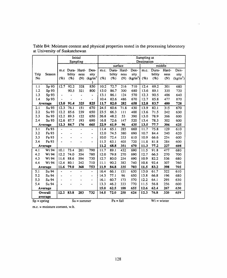
Table B4: Moisture content and physical properties tested in the processing laboratory at University of Saskatchewan
Trip Season No
Initial
m.c Dura- Hard- Den- bility ness sity
(a) (96) (NI (kg/m3
Average 13.0 91.4 325 825 2.1 Su93 12.3 76.1 151 670 2.2 Su 93 12.2 85.6 239 650 2.3 Su 93 12.2 89.3 122 650 2.4 Su 93 12.6 87.7 193 690
Average 12.3 84.7 176 665 3.1 Fa93 - - 3.2 Fa93 - - 3.3 Fa93 - - 3.4 Fa 93 - -
Average
Average 11.6 79.0 368 753 5.1 Su 94 - -
Sampling at ~ e s h n a t i o n
surface middle
bility ness sity biiity ness sity
Sp = spring SU = sumrner
m.c. = moisture content, w.b.
F a = fall Wi = winter

of the cube pile in the container after loading and at the time of unloading. These profiles
are depicted in Figure B4. A slight drop in the height of cube pile in the container, and a
more uniform profile were observed. Cube spoilage will be discussed in the next section.
Table B5 lists the inspectors report on the cube quality inspected by OMIC at the
time of unloading. "Good" means that no visible mold was observed. Ten percent mold
means that 10% (estimated) of the total content load of cubes was judged moldy. A little
mold means that patches of mold were observed on the cubes.
Condensation occurred at both the above cube surface and on the wall (and ceiling)
during winter and summer trips, though its occurrence was higher in summer than in
winter. The condensation board in the container showed that the surface condensation
started in Canada and occurred daily. Condensation disappeared once the container was
on the ocean. The condensation reappeared when the container arrived in Taiwan.
B.4 Discussion
B.4.1 Cube spoilage
In addition to visible mold growth, cubes lost durability and hardness in transit.
Table B4 lists the averages of moisture contents and other physical properties during each
shipment. For the summer shipments in 1993 and 1994 the cube surface moisture content
increased substantidly, almost from 1 1%- 12% to 25%-27%. This high moisture with
prevailing high temperatures caused mold growth. The data in Table B4 also show that
other properties such as durability and hardness decreased especiaily for those sarnples
removed from the surface of the pile. Cubes removed from the middle of the pile showed
no mold and a lesser change in properties compared to the surface cubes.
One interesting point to note is that the density of individual cubes decreased during
transit indicating a net increase in the volume of the cubes. Figure B4 shows that there
was a net drop in the height of the cube pile in the container. One may then conclude that
cube packing in the container increased substantiaIly during transit. It should also be
noted that the Iower density for cubes meant that they lost their integrity via expansion.

Front Rear
Figure B4: Typical cube profiles within container: a) at loading, b) during transit, c ) upon anival.

Table B5: Humidity ratio of the headspace.
MOLU2045782 MOLU2039060 MOLUS 127424 MOLU8098244
Average MOLU8040068 MOLU2 134200 MOLU2086380 MOLU803 1744
Average
MOLU806944 1 MOLU2 125595 MOLU8 168974 MOLU8007542
Average
GSTU763369 1 GSTU8622829 MOLU2 17490 1 MOLUO 1 10636
Average
ILTU5443660 UFCU2220506 GSTü836 1598 GSTU6704785
Average Overall average
Sp = spring SU = sumrner
Inspection 1 Load 1 Sail
good good good good
10% moldy 10% moldy 10% moldy 14.72 16.00 10% moldy
14.72 16.00
good good good good
good g ood good good
good 12.86 13.39 good 11.06 10.13
little mold 9.29 11.32 little mold 10.09 10.04
10.83 11.22
ratio. @,o. at
Arrivnl 1 Unloïd
13.95 1 18.93 Wi = winter

B.4.2 Moisture content
The fact that the moisture content of cubes increased during shipment indicated that
moisture was added to the space within the containers. Table B4 showed that the moisture
content of the cube pile was either unchanged or slightly increased even for cubes
removed from the middle of the pile. Therefore the source of moisture must have been
from outside sources.
Relative humidity of the space above the cubes and the air temperature were used to
calculate absolute hurnidity (g of H20 per kg of air) using Psychometric formulas given
in the ASAE Standard D371.2 (ASAE, 19944). Humidity ratio, H, was a measure of the
arnount of actual water in the air in the form of vapor. The humidity ratio was used to
determine if water was added or removed from the air during transport.
Figure B5 shows a typical plot of absolute humidity (H) during a January 1994
shipment. The hurnidity ratio in the space was about 3 g/kg of air in the container after
the container was loaded with cubes. The absolute humidity (H) increased to about 4 @kg
by the time the container was placed on the vessel. There was an increase in H to about
10 g/kg when the container arrived in Taiwan. At that point there was a fluctuation in H
frorn 8 to 13 gfkg.
Table B5 summarizes the absolute hurnidity (H) of air inside each container at the
time of loading, sail date, arriva1 in Taiwan, and at the time of unloading. The data show
that the amount of water in the airspace increased with the length of time cubes remained
in the container. The overall average hurnidity was 8 @cg at the tirne of Ioading. It
increased to 9.1 g/kg in Vancouver, to 13.95 g/kg in Taiwan, and finally to 18.93 @kg rit
the time of unloading.
The data in Table B5 show that the most pronounced moisture accumuIation in the
container was during warmer months and during the time when a container was waiting
to be unloaded in Taiwan. It appears that the source of increased humidity is air
movement from the outside to the inside of the container. No discernible difference in the
humidity ratio between different locations of the container on the vessel was detected. It
is then concluded that hurnidity of the outside air might be the source of humidity

35
Canada i Ocean Taiwan
T nippmg aare. ~ u i y LWYJ
f
- shipping;date. Jan 7/94
O 5 1 O 15 20 25 30 35
Transportation period, d
Figure B5: Typical hurnidity ratio versus tirne of the shipment during surnmer and winter.
increase in the container. Rain or snow, and rnist were not a factor.
B.4.3 Location of the container on the vessel
Table B6 lists the maximum, minimum, and average temperature of the container
ceiling during transit. The ceiling temperahue was the most sensitive indicator of the
changing environment around the container. Therefore this temperature was used to test
the effect of the segments of the trip (Canada, ocean, Taiwan) and placement of the
container on the vessel. The degree of temperature fluctuation was calculated around a
moving average. Equation B 1 was used to calculate the average:

Table B.6: Maximum, minimum, average, and deviation of ceiling temperatures from the mean.
Sipment ID 1 In- 1 placement
1 . 1 MOLU2045782
spnng 93 1.2
MOLU2039060 spring 93
1.3 MOLU8 127424
spring 93 2.3
MOLU2086380 sumrner 93
3.1 MOLU806944 1
faIl 93
fa11 93 4.1
GTSU763369 1 winter 94
- -
4.2 GSTU8622829
winter 94 4.3
GSTU2 t 7490 1 winter 94
5.1 ILTU5443660
sumrner 94 5 -2
UCFCU2220506 summer 94
5.3 GSTU8361598
Ocean BD-AW Taiwan Canada Ocean BD-BW +-
Taiwan Canada Ocean D-P Taiwan Canada Ocean D-S
Taiwan Canada Ocean D-S
Taiwan Canada Ocean D-P Taiwan Canada Ocean BD-BW
Ocean 1 D-S
Ocean BD-BW Taiwan
Ocean Taiwan
Ocean BD-BW Taiwan Canada Ocean BD-AW + Ocean 1 BD-AW
BD-BW summer 94 Taiwan
Ceiling temperature, O C
N. Max Mi Avg. Devia- data n. tions

where Tm is the mean temperature and a is a smoothing factor (a=0.25 was used). the
subscnpt 'j' indicates the data point. The temperature deviation (s-d.) was calculated by:
where n was the number of the data points. Equation (B.2) was calculated for each
segment of the trip. The resulting averages were rounded to whole number and listed in
Table B.6.
Table B6 shows that the ceiling temperature depended on the season, transit period.
and placement of the container on the vessel. The maximum temperatures ( 7 5 ' ~ . load
1.1) was recorded in Taiwan, and the minimum temperature (-16O~. load 4.2) was
recorded in Canada. Generally the average temperatures in Canada were IOOC to 2 0 " ~
lower than the average ceiling temperature in Taiwan. In al1 cases the least variations
were during the ocean trip, followed by Canada, and Taiwan.
The variations in temperatures for the below deck placement were 1. 0, O compared
to 2, 3, 2 for the above deck placement (Spring 1993, Fa11 1993 and Winter 1993).
Adequate data for the Summer 1993 and for the Summer 1994 were not available to
compare the above deck and the below deck placements. Judging from the few data
available, we rnay conchde that there was less variation in ceiling temperature for the
below deck containers. It is interesting, however, to note that the average temperature is
warmer below the deck than above deck (probably due to engine heat)
Data are available from two shipments to compare above deck starboard and port
side container placements (D-S and D-P, Fa11 1993 and Winter 1994). Variations were
1°C for the starboard side and 3°C and 2°C for the port side. Port side containers were
exposed to sun whereas the starboard side was relatively shaded. To compare below water
and above water (BW and AW), the following variations 3O , 8O, 2°C for the AW and Io.
O", 0°C for the BW were found. Less variation was evident for the containers transported
below the water line.

APPENDIX C
A SAMPLE OF DATA FOR ONE SHIPMENT (JULY 1993)

1 Shipping Date:July 28/93 Note: T,= roof temperriture,"C Cs= Surface condensation 2 Container: Molu 2086380 Ti= air temperature,"C C,= roof condensation 3 Cube Condition: 10% moldy T,= surface temperature,"C 4 Date of Unloading: Sept 4/93 (Julian 247) T e 60 cm below the surface temperature."C 5 Extemal Extemal 6 RH ternp."C RH tempV0C 7 Day T, Ta T, Ta Cr Cs % Air Sea Day T, Ta T, T60 Cr Cs 8 Air Sea -- 8 0.67 39 28 20 18 50 50 64 17.00 21 19 15 14 19 50 78 23 23
