hydroscat-2 user's manual
TRANSCRIPT

HydroScat-2Spectral Backscattering Sensor &
Fluorometer
User’s ManualRevision I
Hydro-Optics, Biology & InstrumentationLaboratoriesLighting the Way in Aquatic Sciencewww.hobilabs.com [email protected]

iiii
Current Firmware Version: 1.92Other firmware versions may differ in some respects. Contact HOBI Labs forinformation on how to upgrade HydroScat firmware.
RevisionsI, December, 2011: Correct equation symbols in section 9; formatting; updatesection 2.2.H, June 15, 2008: Add notes about factory maintenance and cleaning windows(section 2).
G, June 6, 2007: Correct and clarify sigma correction, sections 9.5 and 9.6F, October 22, 2004: Update description of sigma correction to reflect changes inHydroSoft 2.7 (section 9.6). Add STARTNOLOG command (8.3.19)E, December 23, 2002: Remove references to PDI box. Add dimensions of deepsea rated version to Figure 4 (page 7). Corrected time format in “T” packet,section 9.3.2., and checksums in example packets (section 9.1) . Add descriptionof exponential sigma correction (section 9.6)May 20, 2002: Revise Shutter command (section 10) and include more referencesto shutter throughout; add oil-encapsulated depth sensor (0); add note aboutpreserving data in case of reset (section 11); add to discussion of magnetic switchbehavior (section 5.9); update calculation of bb and add description ofBackscattering Parameters in HydroSoft (9.5) recommend minimum start delayand warm-up time of 3 seconds; grammatical and format corrections.February 20, 2002: Update addresses, contact informationJune 15, 2001: Add anti-fouling shutter (section 10 and elsewhere).February 16, 2001: Start of revision tracking. Extensive reorganization, changesto incorporate HydroSoft, separate HydroScat-2 from HydroScat-6.

iiiiii
TABLE OF CONTENTS
1. INTRODUCTION ................................................................................................................................ 1
1.1. OVERVIEW........................................................................................................................................ 11.2. OPTICS.............................................................................................................................................. 11.3. ELECTRONICS ................................................................................................................................... 21.4. FLUORESCENCE MEASUREMENTS..................................................................................................... 3
2. PRECAUTIONS AND MAINTENANCE .......................................................................................... 5
2.1. PRECAUTIONS................................................................................................................................... 52.2. CALIBRATION AND FACTORY MAINTENANCE................................................................................... 52.3. GENERAL CLEANING ........................................................................................................................ 52.4. WINDOWS......................................................................................................................................... 62.5. PRESSURE TRANSDUCER................................................................................................................... 62.6. CONNECTOR ..................................................................................................................................... 62.7. MOUNTING AND DEPLOYMENT......................................................................................................... 6
3. QUICK START .................................................................................................................................... 9
3.1. SETUP ............................................................................................................................................... 93.2. COLLECTING DATA........................................................................................................................... 93.3. DOWNLOADING DATA FROM THE HYDROSCAT.............................................................................. 103.4. DISCONNECTING............................................................................................................................. 103.5. SWITCH-ACTIVATED LOGGING (SEE ALSO SECTION 5.9)................................................................. 10
4. HYDROSOFT SOFTWARE ............................................................................................................. 13
4.1. INSTALLING HYDROSOFT ............................................................................................................... 134.2. REMOVING HYDROSOFT................................................................................................................. 13
5. COLLECTING AND HANDLING DATA....................................................................................... 15
5.1. PRIMARY DATA .............................................................................................................................. 155.2. HOUSEKEEPING DATA .................................................................................................................... 155.3. CALIBRATION DATA....................................................................................................................... 15
5.3.1. Loading Calibrations.............................................................................................................. 155.3.2. Viewing And Editing Calibration Data................................................................................... 16
5.4. CONNECTING .................................................................................................................................. 165.4.1. Connection Dialog Box........................................................................................................... 175.4.2. Manual Connection................................................................................................................. 175.4.3. Search Connection.................................................................................................................. 175.4.4. Load Calibration From Instrument Option............................................................................. 17
5.5. LOGGING SETUP ............................................................................................................................. 185.5.1. Noise Levels and Sampling Rates ........................................................................................... 19
5.6. SETTING THE HYDROSCAT’S REAL-TIME CLOCK........................................................................... 205.7. LOGGING VERSUS REAL-TIME DATA ............................................................................................. 205.8. LOG MEMORY CAPACITY ............................................................................................................... 205.9. USING THE MAGNETIC SWITCH...................................................................................................... 205.10. DOWNLOADING LOGGED DATA.................................................................................................... 21
5.10.1. Basic Procedure.................................................................................................................... 215.10.2. Details................................................................................................................................... 22
5.11. PROCESSING DOWNLOADED DATA............................................................................................... 235.11.1. Making Calibrated Data Files .............................................................................................. 245.11.2. Making Raw Decimal Files................................................................................................... 25
5.12. RAW DATA FILE FORMAT............................................................................................................. 255.13. CALIBRATED DATA FILE FORMAT................................................................................................ 25
6. ELECTRICAL CONNECTIONS ..................................................................................................... 27

iviv
7. INTERNAL BATTERY..................................................................................................................... 29
7.1. BATTERY CAPACITY....................................................................................................................... 297.2. LOW-VOLTAGE CUTOFF ................................................................................................................. 307.3. CHARGING...................................................................................................................................... 307.4. BATTERY DISABLE ......................................................................................................................... 30
8. DIRECT COMMUNICATION AND COMMANDS ...................................................................... 33
8.1. COMMUNICATION PROTOCOL......................................................................................................... 338.2. COMMAND CONVENTIONS.............................................................................................................. 338.3. ROUTINE COMMANDS..................................................................................................................... 33
8.3.1.BURST,on,warmup,duration,cycle,totalDuration,logPeriod,startDelay,autoStart,sleepOnMem
Full 338.3.2. CHANNELS ............................................................................................................................ 348.3.3. CLEARRAM............................................................................................................................ 348.3.4. CLEARLOG ............................................................................................................................ 358.3.5. CLOSE,time ............................................................................................................................ 358.3.6. D ............................................................................................................................................. 358.3.7. DATE,mm/dd/yyyy hh:mm:ss.................................................................................................. 358.3.8. DIR.......................................................................................................................................... 358.3.9. DOWNLOAD,cast................................................................................................................... 358.3.10. H ........................................................................................................................................... 368.3.11. ID .......................................................................................................................................... 368.3.12. LOG,period,delay,sleepOnMemFull,autostart,burstMode,burstWarmup,burstDuration,burstCycle,totalDuration ......... 378.3.13. OPEN,time ............................................................................................................................ 378.3.14. RAM ...................................................................................................................................... 378.3.15. SHUTTER,auto,time [Firmware 1.80] ................................................................................. 388.3.16. SLEEP,secs ........................................................................................................................... 388.3.17. SLEEPINFO ......................................................................................................................... 388.3.18. START,delay ......................................................................................................................... 398.3.19. STARTNOLOG,delay [added in firmware 1.80]................................................................... 398.3.20. STOP..................................................................................................................................... 398.3.21. STORELOG .......................................................................................................................... 398.3.22. T ............................................................................................................................................ 398.3.23. TIME,hh:mm:ss..................................................................................................................... 398.3.24. TIMERES,mode..................................................................................................................... 40
8.4. ‘TIME RESOLUTION: LOW (1 SECOND)SPECIAL-PURPOSE COMMANDS ........................................... 408.4.1. AGAIN,channel,auto............................................................................................................... 408.4.2. BAUD,rate .............................................................................................................................. 408.4.3. GAIN,channel,gain ................................................................................................................. 408.4.4. GCF,address,Baudrate ........................................................................................................... 418.4.5. X.............................................................................................................................................. 42
9. DATA PROCESSING REFERENCE............................................................................................... 45
9.1. RAW DATA FORMATS..................................................................................................................... 459.2. “D” PACKET FORMAT..................................................................................................................... 45
9.2.1. Example “D” Packet: ............................................................................................................. 459.2.2. “D” Packet Structure ............................................................................................................. 459.2.3. Packet Flag............................................................................................................................. 469.2.4. Packet ID ................................................................................................................................ 469.2.5. Time ........................................................................................................................................ 469.2.6. Snorm...................................................................................................................................... 469.2.7. Gain/Status ............................................................................................................................. 479.2.8. DepthRaw ............................................................................................................................... 47

vv
9.2.9. TempRaw ................................................................................................................................ 479.2.10. Error ..................................................................................................................................... 479.2.11. Checksum.............................................................................................................................. 489.2.12. Terminator ............................................................................................................................ 48
9.3. “T” PACKET FORMAT (FIRMWARE 1.60 AND LATER) ...................................................................... 489.3.1. Example “T” Packet:.............................................................................................................. 489.3.2. “T” Packet Structure .............................................................................................................. 48
9.4. “H” PACKET FORMAT..................................................................................................................... 499.4.1. Example “H” Packet: ............................................................................................................. 499.4.2. Time ........................................................................................................................................ 509.4.3. SigOff, Ref, RefOff .................................................................................................................. 509.4.4. Back ........................................................................................................................................ 509.4.5. VsupA, VsupB, Vback.............................................................................................................. 509.4.6. Aux .......................................................................................................................................... 509.4.7. Checksum................................................................................................................................ 509.4.8. Terminator .............................................................................................................................. 50
9.5. CALCULATING ß AND BB .................................................................................................................. 519.6. SIGMA CORRECTION....................................................................................................................... 529.7. CAL FILE FORMAT.......................................................................................................................... 55
10. ANTI-FOULING SHUTTER OPTION.......................................................................................... 57
10.1. DESCRIPTION ................................................................................................................................ 5710.2. WIRING......................................................................................................................................... 5710.3. OPERATION................................................................................................................................... 5810.4. OPERATION TIME.......................................................................................................................... 5810.5. SHUTTER-SPECIFIC COMMANDS ................................................................................................... 58
10.5.1. SHUTTER,auto,time [Firmware 1.80] ................................................................................. 5810.5.2. OPEN,time ............................................................................................................................ 5910.5.3. CLOSE,time .......................................................................................................................... 59
10.6. OTHER RELEVANT COMMANDS.................................................................................................... 59
11. TROUBLESHOOTING ................................................................................................................... 61
12. CUSTOMER SERVICE................................................................................................................... 63

vivi

11
1. INTRODUCTION
1.1. OverviewThe HydroScat-2 is a self-contained instrument for measuring optical
backscattering (bb) at two wavelengths in natural waters. Its unique opticalgeometry and sophisticated electronics also provide simultaneous measurement ofthe fluorescence excited at the longer wavelength by the shorter wavelengthsource. The HydroScat-2 includes a depth transducer, rechargeable batteries, adata logger with real-time clock, and an external switch for controlling logging.The data logger supports a wide range of sampling rates, as well as burst-modesampling for collection over extended periods.
1.2. OpticsThis brief overview introduces the key concepts necessary for
understanding the HydroScat’s measurements. The optical principles are coveredin much greater detail in “Instruments and Methods for Measuring the Backward-Scattering Coefficient of Ocean Waters”, by Robert A Maffione and David R.Dana, Applied Optics Vol. 36, No. 24, 20 August 1997.
The HydroScat-2 has two independent channels, each sensitive to adifferent narrow range of optical wavelengths. Each channel consists of separatesource and receiver optics. The source produces a beam of light in the water, andthe detector collects a portion of the light that is scattered out of that beam by thewater.
Each source beam originates from a light-emitting diode (LED) selected tomatch the desired measurement wavelength. The beam from the LED enters thewater at an angle approximately 20 degrees from normal. The receiver consists ofa prism that bends the field of view toward the source beam, a band-passinterference filter that determines the exact wavelength range of the measurement,and lens that focuses the received rays onto a silicon detector.
The divergences of the source beam and receiver field of view, the anglesof the prisms, and the distance between the source and receiver windows,determine the range of scattering angles over which the measurement is made.The HydroScat geometry results in a measurement centered on a scattering angleof 140.
The fraction of the transmitted light scattered in the desired range of anglesis extremely small, and one of the prime considerations in the optical design is

22
maximizing this inherently low throughput. Thus we maintain at least a 2 cmopen aperture throughout the optical path.
SEN
SOR
FAC
E
DISTANCE
SOURCE BEAM
PRIMARY SENSING VOLUME
RECEIVER FIELD OF VIEWR
ELA
TIVE
SEN
SITI
VIT
Y
Figure 1 Side View of Backscattering Measurement Geometry
1.3. ElectronicsThe inherently low optical throughput of the backscattering measurement
demands very sensitive electronics. In clear water the backscattering signalsarriving on the detector may be as low as a few picowatts. At the same time,natural background light may be orders of magnitude larger.
To separate backscattering signals from background light, the LEDs aremodulated at audio frequencies, and synchronous receiver electronics used todiscriminate against interfering signals. Each channel has a different frequency toprevent any crosstalk between channels. This also allows us to discriminatebetween backscattering and fluorescence (see section 1.4).
To allow measurement in a wide range of waters, and to accommodate therequirements of our calibration procedure, the gain of each channel can be set toone of five settings spaced a decade apart. Only three of these settings are used innormal measurement situations; the lowest two are used primarily for calibration.The HydroScat normally selects the appropriate gain automatically, based on theamount of backscattering detected as well as the amount of background light.

33
In order to compensate for residual electronic offsets, the HydroScatperiodically turns off each LED briefly to measure the receiver output in theabsence of signal. The LEDs are turned off for 0.1 second approximately every 2seconds, and the resulting offsets are continuously averaged and subtracted fromthe signals. Note that this is not the modulation, referred to previously, thatseparates the backscatter signals from each other and from background radiance;those modulations are too rapid to be visible.
SOURCE1 (Blue)
SOURCE2 (Red)
DETECTOR2 (Red)
DETECTOR1 (Blue)
Figure 2 HydroScat-2 Front End Cap
1.4. Fluorescence MeasurementsThe HydroScat is optimized for measuring elastic backscattering, but offers
a secondary capability of measuring fluorescence.Because each LED in the HydroScat is modulated at its own frequency,
fluorescence excited by a particular channel can be identified by the excitationchannel’s characteristic frequency, even though its emission falls into the opticalbandwidth of another channel. The HydroScat receiver channels can be “tuned”under software control to the frequency of another channel’s source, allowingthem to detect fluorescence instead of backscattering. If the field of view of achannel intersects the beam produced by another channel, it can collectfluorescence from that channel as efficiently as it does backscattering from its ownsource.
The HydroScat-2’s two channels are configured with crossing beams andfields of view (see Figure 2) so that the longer wavelength channel, usually 676nm, detects both backscattering from its own source, and fluorescence excited by

44
the shorter wavelength source, usually 470 nm. The received signal from thelong-wavelength channel is sent to two sets of detection electronics, one tuned toeach source. Thus the HydroScat-2 simultaneously measures backscattering attwo wavelengths and fluorescence at one wavelength.
The fluorescence channel is not calibrated to an absolute standard, so itsdata are reported in arbitrary units.
MAGNETIC SWITCH("ON" AS SHOWN)
"ON" INDICATOR
ZINC ANODE
LIFTING EYE
MCBH8M CONNECTOR
PRESSURE TRANSDUCERDRAIN HOLES (OLDERMODELS ONLY)
ENCAPSULATED PRESSURE TRANSDUCER(NEWER MODELS)
Figure 3 HydroScat-2 Back End Cap

55
2. PRECAUTIONS AND MAINTENANCE
The HydroScat-2 is a sophisticated optical instrument that requires regularcare and calibration. HOBI Labs is not responsible for the accuracy of data if youdo not observe the following recommendations.
2.1. Precautions Protect the windows. Cover the instrument face whenever possible.
Do not use acetone to clean any part of the instrument.
Thoroughly clean the HydroScat with fresh water before storing it.
Avoid letting the sensor sit in direct sun on deck. If the watertemperature is very different from the temperature on deck, let theinstrument stabilize in the water for 10 minutes before collectingdata.
See section 7 for information about maintaining internal batteries.
2.2. Calibration and Factory MaintenanceWe recommend calibrating the HydroScat–2 every six months or 200 hours
of operation, whichever comes first.With the proper equipment, available from HOBI Labs, users can perform
their own calibrations. For more information about the equipment and proceduresinvolved, see the HOBI Labs Backscattering Calibration Manual (available atwww.hobilabs.com).
NOTE: Even if you perform your own calibrations, it is very important toreturn the HydroScat-2 to HOBI Labs, preferably annually, for a completefunctional test and check-out. Inspection and testing by trained factory personnelcan uncover items that may not be evident to users, but which can affect thereliability or endurance of the instrument.
2.3. General CleaningUpon removing the instrument from the water, rinse it thoroughly with
fresh water, and rinse the windows with distilled or deionized water. Periodicallyinspect the windows for contamination.

66
2.4. WindowsHydroScats have acrylic windows that are easily scratched. Minor
scratches will not seriously compromise the measurements, but the windows mustbe treated carefully to avoid abrasion. Do not use acetone or abrasive cleaners.Do not over-clean the windows. Unless the windows become visibly dirty duringuse, it is usually sufficient to rinse them with clean fresh water each time theinstrument is removed from the water. If necessary, clean them with a mild liquidsoap or lens-cleaning solution. Occasional cleaning with alcohol is also safe, butusually not necessary.
2.5. Pressure TransducerIf your HydroScat-2 has an encapsulated pressure transducer with a plastic
wick attached, use care to ensure the wick is not damaged so as to allow thesilicone oil to leak out. If your HydroScat-2 has the older style of transducerunder the suspension eye (see Figure 3 on page 4), flush the pressure transducerwith fresh water when rinsing the instrument. If possible, spray water directly intothe drain holes, but not at very high pressure.
2.6. ConnectorOccasionally apply silicone lubricant to the connector pins. The connector
should mate smoothly without great force. Well-lubricated connectors alsodisconnect fairly easily, so use the connector locking sleeve during deployment.
2.7. Mounting and DeploymentThe HydroScat can be suspended vertically from the metal eye on the
connector end cap, or strapped to another support. If mounting it to anotherstructure, protect the finish on the case from direct metal contact.
To ensure that the HydroScat does not detect reflections from any objects,keep a 30-degree cone in front of the windows clear for at least 1 meter. Evenobjects that appear very non-reflective, or are well out of the nominal samplingvolume, can create substantial offsets in the backscattering measurement. It isusually permissible to violate this conservative 30-degree limit, but you shouldverify by experiment that the instrument’s readings are not elevated if you do so.
It is usually preferable for the sensor to face directly down in the water, tominimize the effect of background illumination. However in shallow water over areflective bottom, under bright solar illumination, light reflected into the windowsmay cause high noise levels or, in extreme cases, saturation. In such situations itmay be advantageous to mount the sensor horizontally so that the backscatteringreceivers do not face the bottom. Some experimentation may be required in suchcases.

77
HydroScats equipped with internal batteries can be deployed with only amechanical cable or attached to an existing package without additional cabling. Ifthe HydroScat is attached to an existing package, make sure that the field of viewof the sensor is unobstructed as mentioned above.
MCBH8M Connector
KEEP 30° CONE CLEAR OFOBJECTS
Standard version: 9.00" [22.9 cm]Deep Ocean version: 10.9" [27.7 cm]
Sta
ndar
d:4.
60"[
11.7
cm]
Dee
p:5.
4"[1
3.7
cm]
Figure 4 HydroScat-2 Side View


99
3. QUICK START
3.1. Setup1) Install HydroSoft on your computer (see section 4.1 or the HydroSoft
manual).2) Connect the supplied data download/charging cable to the appropriate
port on your computer.3) Connect the cable to the underwater connector on the HydroScat.4) Plug the cord from the battery charger transformer into the barrel
connector on the data cable.5) Plug the battery charger transformer into a 120 VAC jack.
6) Run HydroSoft by selecting it on the Windows Start menu.
7) Click (or select Connect from the Instrument Menu).
8) Click the Search button.9) After a short time HydroSoft should identify the instrument, load its
calibration, and close the Connect dialog box. If your HydroScat isequipped for an anti-fouling shutter (see section 10) and programmed toopen the shutter at the time it wakes up, it may not respond toHydroSoft’s initial query, and you may need to repeat the search.
10)Select Set Date/Time… from the HydroScat menu.
11)Click Set Time to synchronize the HydroScat clock with yourcomputer’s clock. This will take several seconds. Then click Close toclose the Date/Time dialog box.
3.2. Collecting Data12)Select Sampling Options… from the HydroScat menu.13)For testing purposes, we recommend the following settings:
Sample Rate: 2 per secondStart Delay: 0 secondsBurst mode: unchecked
14)Select Plot Vs. Time from the Graph menu.

1010
15)Click (or select Start from the HydroScat menu). This willcause data to be logged in the HydroScat’s logging memory as well assent to HydroSoft.
16)If no data are visible after a short time, click , and the plot will zoomas needed to show all data.
17)To adjust the way data are displayed, double-click on the graph, orselect Properties… from the Graph menu.
18)Click (or select Stop from the HydroScat menu).
19)Close the open data file by selecting Close from the File menu, orclicking on the button. If desired, save the file when prompted.
3.3. Downloading Data From the HydroScat20)Select Get Data From Instrument from the HydroScat menu.21)After several seconds a directory of casts in memory will appear. The
last cast listed should be the one you just recorded. If that cast is notalready highlighted, click on it to highlight it, or click the Select Allbutton.
22)Click the Browse… button to select a directory in which to savedownloaded data files. In the resulting dialog box, select a directoryand click the Select button.
23)If it is not already checked, check the Create calibrated data (.dat)files option.
24)Click the Download button to begin transferring data casts.
3.4. Disconnecting25)After you are finished communicating with the HydroScat, select
Disconnect from the HydroScat menu. When asked “Put HydroScatto sleep before disconnecting?” click Yes.
26)Unplug the battery charger from AC power.27)Unplug the cable from the HydroScat’s underwater connector.
3.5. Switch-Activated Logging (see also section 5.9)28)To start a cast when the HydroScat is asleep and disconnected from the
computer, move the magnetic switch to the on position (see Figure 3 onpage 4).

1111
29)To end a cast, return the magnetic switch to the off position.


1313
4. HYDROSOFT SOFTWARE
HydroSoft is HOBI Labs’ Windows-based software for communicatingwith HydroScats as well as other instruments. Instructions in this manual assumeyou are using HydroSoft to communicate with your HydroScat, and cover itsprimary functions. You may wish to consult the separate HydroSoft manual for amore complete description and details.
4.1. Installing HydroSoftHydroSoft is supplied on a CD-ROM with new instruments, and can be
supplied on floppy disks by request. We also recommend you visit our web site(www.hobilabs.com) to check for downloadable updates to HydroSoft. It isinstalled using a procedure that is familiar to most Windows users.
1. Run “InstallHydroSoft.exe” from CD-ROM, or from your computer ifyou have received it through the Internet.
2. Click the “Next” button in the installer’s “Welcome” dialog box.3. Decide whether you would like the HydroSoft application stored in the
default directory shown (normally c:\program files\HOBI Labs). If not,click the “Browse” button to select a different directory, or type thename of a new directory you would like to create.
4. Click “Next” to start the installation.5. When the installation is complete, click “Finish” to exit.It is not normally necessary to reboot your computer unless the installerprogram explicitly instructs you to.
4.2. Removing HydroSoft1. From the Start menu, select “Settings”, then “Control Panel”.2. Double-click on the “Add/Remove Programs” icon.3. Select HydroSoft from the list of programs.4. Click the “Add/remove” button.
OR1. Open the directory into which you installed HydroSoft.2. Double-click on the “unwise.exe” icon, which runs the uninstaller.


1515
5. COLLECTING AND HANDLING DATA
5.1. Primary DataThe primary data reported in every sample are
date and time,
raw scattering for each channel,
the gain of each scattering channel,
pressure, and
internal instrument temperature.
5.2. Housekeeping DataHydroScats record certain “housekeeping” parameters that are not required fornormal data processing, but can be valuable for troubleshooting and for evaluatingthe health of the sensor. They are
battery and external supply voltages,
background radiance on the detectors (in arbitrary units),
reference measurements of the LED outputs, and
signal offsets.Normally the housekeeping data are logged at one-tenth the rate of the main data.That is, every ten samples are followed by one housekeeping sample.
5.3. Calibration DataHydroScats data are transmitted in a partially processed hexadecimal form,
which must be converted to calibrated units. The coefficients required for thisconversion are unique to each instrument, and may be revised from time to timewhen the instrument is recalibrated. HydroSoft requires an appropriate calibrationto be loaded before it can plot or store calibrated data from an instrument or rawdata file.
5.3.1. Loading CalibrationsCalibrations can be loaded either directly from a connected HydroScat, or
from a file on the host computer. To load an instrument’s calibration, check theLoad Calibration From Instrument option while connecting to the instrument

1616
(section 5.4). To load a calibration from a file, choose Select Calibration Filefrom the File menu.
If you select a new calibration file while an instrument is connected, orwhile a raw data file is open, HydroSoft will only load it if it is of a matching type.HydroSoft will inform you if the type does not match. It will also warn you if theserial number of the instrument does not match that contained in the calibrationfile, but it will offer you the option of loading it even if the serial numbers do notmatch.
Once a calibration file is loaded, it remains in effect until a different one isloaded. When you exit HydroSoft, it stores the name of the current calibrationfile. If the Automatically recall last selected calibration file option is selectedin the Preferences dialog box, the file will be reloaded the next time HydroSoftstarts up. If you have more than one data window open in HydroSoft, you canselect a different calibration file for each one. The most recently selected file inany window will be saved as the default.
5.3.2. Viewing And Editing Calibration Data
You can see the details of the current calibration by selecting ViewCalibration from the File Menu. Normally you should not need to modifycalibration data for an instrument, and the fields in the Calibration dialog box arelocked to discourage casual changes. However you can unlock most fields byclicking on the lock icon in the dialog box. Because correct calibration files arecritical to the accuracy of your data, use care when modifying them. To reduceconfusion we encourage you to enter a description, in the comment field provided,of any changes you make.
To save a copy of the currently loaded calibration, select Save Calibrationfrom the File menu.
5.4. ConnectingTo communicate with a HydroScat, HydroSoft must open the appropriate
computer port at the correct baud rate. The following dialog box allows you tocontrol this process.

1717
5.4.1. Connection Dialog Box
This dialog box appears each time you
select Connect from the Instrument menu,
click on the Connect button in a data window,
attempt an operation that requires a connection, if a connection hasnot yet been established.
5.4.2. Manual Connection
If you click the Connect button, HydroSoft will open the currently selectedport at the selected baud rate. Normally you need not select an instrument type,because HydroSoft will always request identification information from theinstrument. If it receives a reply sufficient to identify the instrument, it willproceed with the connection and close the dialog box. If not, it will notify you andask whether to open the connection anyway. In you instruct it to, it will proceedon the assumption that an instrument of the type you designate is connected.
If your HydroScat is equipped for an anti-fouling shutter (see section 10),under some circumstances its response to HydroSoft’s query may be delayed bythe process of opening the shutter, and HydroSoft may report that no instrumentwas detected. In this case, simply click the Connect button again.
5.4.3. Search Connection
If you click Search, HydroSoft will ignore the selected port and baud rate,and attempt a connection to each port, at each baud rate (from 4800 to 57600),until it receives valid identifying information from an instrument. The dialog boxwill automatically close if a valid connection is found.
5.4.4. Load Calibration From Instrument Option
If Load Calibration From Instrument is checked at the time an instrumentis connected, HydroSoft will prompt the instrument to transmit the calibrationinformation stored in the instrument’s memory. This will override the currently

1818
selected calibration file, if any. See section 5.3 for more information aboutcalibration files.
5.5. Logging SetupHydroScats can be programmed to collect data continuously at rates from
0.1 Hz to 10 Hz, or intermittently to allow autonomous logging for long periods.In HydroSoft, you can set these parameters in the following dialog box, whichappears when you select Sampling Options… from the HydroScat menu.
When the Sampling Options dialog is first open, it may take severalseconds for the current settings to be retrieved from the HydroScat. Similarly,when you click the Apply button there will be a noticeable delay while HydroSofttransmits, then confirms, the new settings. This confirmation is important becauseit allows you to check that the settings were entered as you intended. TheHydroScat may reject settings it cannot support—for example, burst lengths thatare longer than the burst interval.
Sample Rate and Sample Period, by definition, have an inverserelationship. Changes you make to one will automatically affect the other. Notehowever that the period, which has a resolution of 0.01 second, is the controllingparameter. Therefore some exact sample rates are not available. For example, ifyou enter a rate of 3 per second, the calculated period will be rounded to 0.33 s,and the rate will be set to 3.03 per second.
When logging is started, either by software command or by turning on theexternal switch, the HydroScat will wait for the number of seconds specified by

1919
Start Delay, then data will be logged according to the given Sample Period. Ifburst mode is on, the sampling continues until the Burst Length has elapsed, atwhich time the sensor goes into its low-power sleep state. The bursts repeataccording to the period set by Burst Interval. At the beginning of each burst, theHydroScat will wait for the number of seconds specified in Burst Warmup beforecollecting its first sample. To guarantee that the first sample is valid and theinstrument gains are set properly, the warm-up should be set to 3 seconds or more.Whether or not burst mode is on, sampling stops upon receipt of a software stopcommand, when the external switch is turned off, or when the battery becomesexhausted.
In the example above, the burst-mode parameters are inactive because burstmode is not on. To edit the burst-mode parameters you must first check the BurstMode On option.
If Start on power-up is checked, the HydroScat will begin logging eachtime power is applied. Note, however that this setting is only relevant after allpower sources, including internal batteries, are turned off. For HydroScats withinternal batteries (i.e. most HydroScats), you must intentionally disable thebatteries (see section 7.4) for this to take effect.
If Make these settings nonvolatile is checked, the settings will be storedin semi-permanent memory and will remain in effect even if the internal computeris reset or all power is removed from the instrument.
If your HydroScat is equipped for an anti-fouling shutter (see section 10)the dialog box will expand to show the shutter parameters.
Before logging you may wish to download and clear data from theHydroScat’s memory (see section 5.10).
5.5.1. Noise Levels and Sampling RatesThe backscattering measurement involves extremely low light levels, and
several factors can contribute to noticeable noise in the measurements, especiallyin clear water. However, noise in the measurements is unbiased, and uncertaintycan be reduced by averaging samples together, or equivalently, lowering theinstrument’s sampling rate. In conditions with low background light, at asampling rate of 1 Hz, the RMS noise level is typically from about 0.0003 m-1 to0.001 m-1 depending on wavelength. Wavelengths shorter than 470 nm tendtoward the higher end of this range, since LED and detector efficiencies fall off atshorter wavelengths. High background light levels can introduce shot noise thatdegrades these figures.
In many circumstances natural variability exceeds the measurement noise.In water containing significant numbers of very large particles—even schools of

2020
fish—the data may show a background scattering level punctuated by spikes ofincreased scattering (as individual large particles pass through the samplingvolume). Depending on your application, you may or may not wish to includesuch spikes in averaged measurements. Higher sampling rates preserve the optionof evaluating the character of the data before averaging or other processing.
5.6. Setting the HydroScat’s Real-Time ClockAlthough it is not necessary for the sensor’s operation, you may wish to set
the real time clock before logging. Select Set Date/Time… from the HydroScatmenu. Click Set Time to synchronize the HydroScat clock with your computer’sclock. If you wish to set the clock to a different time reference, select the SetManually option and enter the correct date and time before clicking Set Time. Ittakes several seconds for HydroSoft to set the clock and reconfirm the setting.When it is finished, click the Close button to close the dialog box.
5.7. Logging Versus Real-Time DataWhenever collecting data in response to a Start command from HydroSoft,
or from its magnetic switch, HydroScats simultaneously transmit them from theirserial port. Data can also be collected on demand, without internal logging, bysending “D”, “T” or “H” commands each time data are required (see section 8 forinformation about the commands, and section 9 for the data formats).
5.8. Log Memory CapacityThe base memory of the HydroScat-2 includes 256K of RAM, of which
most is reserved for data logging. The base memory can hold about 15,000samples (we use the terms “sample” and “packet” interchangeably to indicate a setof simultaneous measurements from all the channels). The optional 1M RAMexpands this to about 65,000 samples. Both RAM options depend on power fromthe internal batteries or another source to retain logged data.
5.9. Using The Magnetic SwitchThe magnetic switch located on the back end cap of the HydroScat (see
Figure 3 on page 4) signals the sensor when to start and stop data logging. Anindicator dot is machined into the end cap and is exposed when the switch is in the“on” position. When switched on, the HydroScat will wake and begin collectingdata as if the START command were sent to it. When switched off, it will stopsampling and go to sleep, as if the STOP and SLEEP commands were sent.
By using the magnetic switch, one can collect an extended series of castswithout connecting to a computer. The starting and ending times of each cast arerecorded in the log memory so that casts can be later downloaded individually or

2121
as a group. The sensor may be wakened from sleep by command from the serialport regardless of whether the switch is “on” or “off”. However the softwareSLEEP command will not work if the switch is “on.”
Because the switch was designed to support operation from the internalbatteries, the switch as originally designed may not operate if an external source ofpower (including batteries) is connected, and its voltage exceeds the voltage of theinternal batteries. A design change in March, 2002 overcomes this limitation oninstruments built since then, and can be retrofitted to older instruments. You cantest this on your instrument by applying 14V from a power supply to the externalsupply input, then operating the switch.
5.10. Downloading Logged DataHydroSoft’s Get Data From Instrument command enables you to view a
list of casts stored in an instrument’s memory, transfer casts from the instrument tofiles on your computer, and erase the instrument’s memory. Casts you transfer arestored in individual files whose location and base name you specify. The castnumber is appended to the name of each file.
5.10.1. Basic Procedure
Connect the HydroScat to your computer’s com port using thesupplied data download cable, start HydroSoft, and use HydroSoft’sConnect command to establish communication.
Select Get Data From Instrument on the HydroScat menu.
A dialog box like the following will appear.

2222
After the directory is loaded, select the cast or casts you wish toretrieve.
Enter a base file name for the downloaded files. The cast numberwill be appended to this base name to create a unique name for eachcast you download.
If necessary, click Browse and select a destination directory for thedownloaded files.
Click Download. Depending on the quantity of data and baud rate,downloading may take some time. Status messages and a graphicalindicator will show the download progress.
To clear the instrument’s memory after verifying the desired castswere downloaded, click Delete All.
Click Close to dismiss the dialog box.
5.10.2. DetailsDepending on the number of casts stored, loading the directory may take a
number of seconds. The status message in the upper left corner indicates if thedirectory is loaded, as above, or if it is in the process of loading.
The memory status line indicates how much of the instrument’s memoryis presently used.

2323
You can select arbitrary groups of casts for downloading. To select acontiguous group of casts, click on the first item in the group, then shift-click onthe last item; or hold down the shift key while using the arrow keys. To select orunselect non-contiguous casts, control-click on them; or hold down the control keywhile using the arrow keys to move through the directory, and press the space barto select or unselect casts.
Data are always collected in raw form. If the Create calibrated data(.dat) files option is checked, a calibrated file will also be created for eachdownloaded cast. The calibration currently in effect for the main data windowwill be applied to these data (see section 5.3 for more information aboutcalibrations).
Because of the way the HydroScat’s memory is configured, it is notpossible to delete individual casts—you can only erase the instrument’s entirememory.
5.11. Processing Downloaded DataWhile HydroSoft allows you to save calibrated data automatically at the
time you collect or download data from a HydroScat, you can also process rawdata files using HydroSoft’s Process Raw Files command. This command alsoallows you to convert raw hexadecimal data to decimal form without calibratingthem.
When you select Process Raw Files, the following dialog box appears:

2424
5.11.1. Making Calibrated Data Files
When Make Calibrated Files is selected, you need to specify a calibrationfile to be used (see section 5.3 for more information about calibration files). Youcan type the path and name of the file directly, or use the Browse… button to openan Open File dialog box. You must also select the file or files you wish toprocess, using the familiar browsing controls. The list in the center right of thedialog box shows those files that are contained in the drive and directory youspecify, and whose names match the File name filter you specify. If Show onlyfiles matching calibration file is checked, as it is by default, HydroSoft willcheck the contents of the files and list only those that contain data from theinstrument type and serial number specified by the selected calibration file.
You can select a single file or an arbitrary group of files from the list.Select a contiguous group of files by shift clicking, and select or deselectindividual files by Ctrl-clicking. Once you start processing, all the selected fileswill be processed.
The processed files will use the same base names as the source files, withtheir extensions set to “.dat”. They will be saved in the directory you specify. If

2525
you wish to save them in the same directory as the raw files from which they aregenerated, you can avoid having to select that directory manually by checking theSame location as raw files option.
5.11.2. Making Raw Decimal FilesThe process for making raw decimal files is identical to that described
above, except that there is no need for a calibration file. Controls relating to thecalibration file will thus be disabled.
When you select the Make Raw Decimal Files option, an additionalInclude Housekeeping checkbox will appear, allowing you to control whetherhousekeeping data will be included in the file in addition to the primary opticaldata.
5.12. Raw Data File FormatHydroSoft names raw data files with the extension “.RAW”. Raw files
start with a header like the following:
[Header]HydroSoftVersion=2.02CreationDate=02/12/01 23:00:55FileType=rawDeviceType=HydroScat-2DataSource=HydroScat-2CalSource=D:\Program Files\HOBI Labs\temp.calSerial=H2000123Config=S2B3[EndHeader]
Future versions of HydroSoft may include additional information betweenthe [Header] and [EndHeader] markers. In any case, everything following the endmarker is included in the exact form in which it was received from the HydroScat.For information on the raw data formats, see section 9.
5.13. Calibrated Data File FormatHydroSoft normally names calibrated data files with the extension “.DAT”.
Calibrated data files start with a header like the following:
[Header]HydroSoftVersion=2.02CreationDate=02/12/01 23:28:42FileType=datDeviceType=HydroScat-2DataSource=Instrument Cast 3

2626
CalSource=D:\Program Files\HOBI Labs\temp.calSerial=H20001Config=S2B3[SigmaParams]ad400=.01aStarFile=D:\Program Files\HOBI Labs\aStar.csvawFile=D:\Program Files\HOBI Labs\aw.csvbbTildeValue=.015C=.1gammad=.011gammay=.014[Channels]"bb440""bb676""fl676"[ColumnHeadings]Time,Depth,bb440,bb676,fl676,bb440uncorr,bb676uncorr,fl676uncorr[Data]36872.9715856481,-29.388,0,1.5536E-04,0,0,1.5536E-04,0,
Future versions of HydroSoft may include additional information betweenthe [Header] and [Data] markers.
The lines following [SigmaParams] are the parameters used for “sigma”correction of the calibrated backscattering, described in section 9.6.
The line following [ColumnHeadings] names the parameters included in thecalibrated data lines. Future HydroSoft files may include additional columnheadings and data parameters, but if so the parameters shown here will remain inthe same order.
Times are stored as double-precision real numbers corresponding to thenumber of days since midnight, January 1, 1900. This is the native format of datesand times in Microsoft Excel.
Depth is in meters, bb is in inverse meters, and is shown first in its “sigma-corrected” form, then in uncorrected form. β(140˚) values, with and withoutsigma correction, are also included if the “include beta in .dat files” option isselected in the Backscattering Parameters dialog (section 9.5).
2727
6. ELECTRICAL CONNECTIONS
A HydroScat can be powered from three sources:1) external 10V to 15V supply,2) internal battery,3) battery charger.Any combination of these source may be safely connected simultaneously.
Power will be drawn from the source with the highest voltage. Nominal operatingpower draw is 1W.
HydroScats can be configured to use either RS232 or RS485 protocols forcommunication. In the RS232 configuration the HydroScat can communicatedirectly through a standard computer serial port. In the RS485 configuration, aconverter or interface card must be provided to allow communication with anRS232 port.
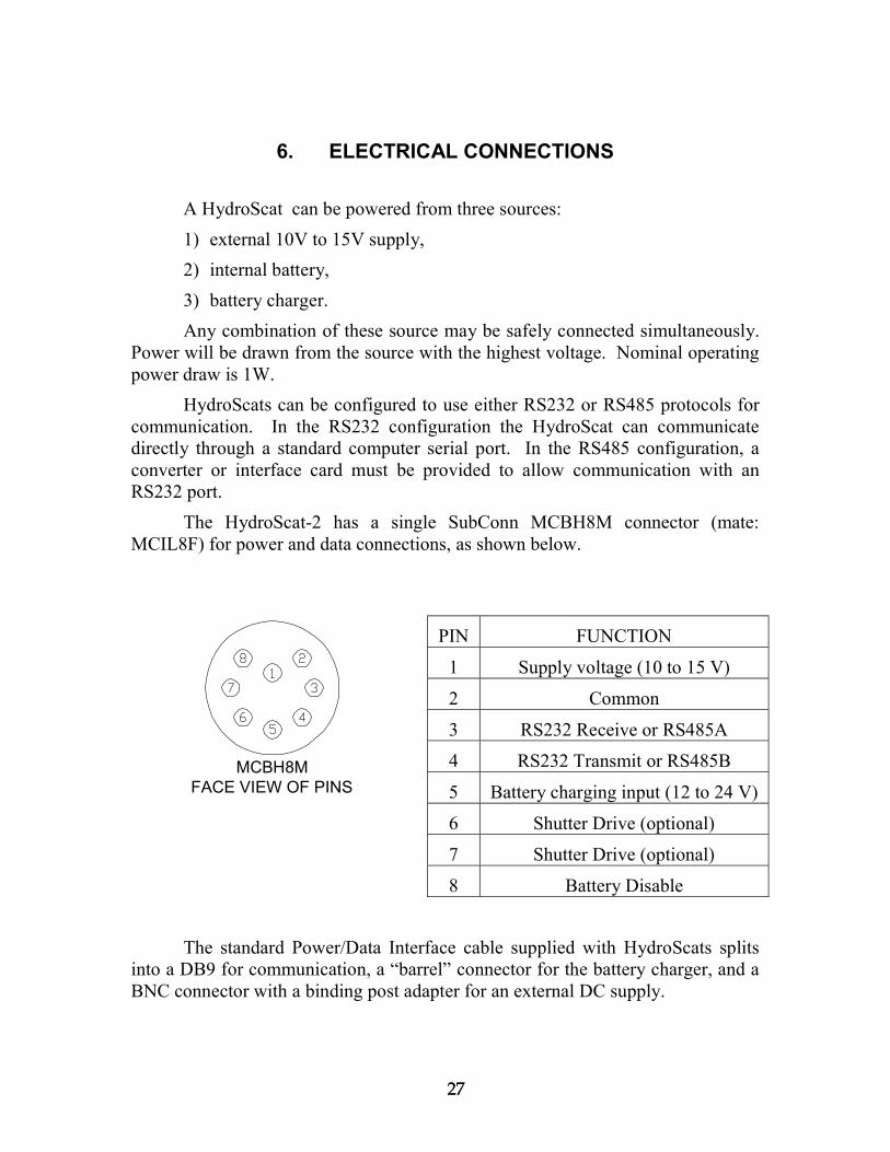
The HydroScat-2 has a single SubConn MCBH8M connector (mate:MCIL8F) for power and data connections, as shown below.
PIN FUNCTION
1 Supply voltage (10 to 15 V)
2 Common
3 RS232 Receive or RS485A
4 RS232 Transmit or RS485B
5 Battery charging input (12 to 24 V)
6 Shutter Drive (optional)
7 Shutter Drive (optional)
8 Battery Disable
The standard Power/Data Interface cable supplied with HydroScats splitsinto a DB9 for communication, a “barrel” connector for the battery charger, and aBNC connector with a binding post adapter for an external DC supply.
MCBH8MFACE VIEW OF PINS


2929
7. INTERNAL BATTERY
HydroScat-2’s are equipped with an internal rechargeable battery, exceptupon special request. The battery consists of 9 nickel-cadmium (Ni-Cd) cells thatprovide capacity sufficient for a day of intensive data collection. With intermittentsampling and proper use of the HydroScat’s low-power modes, it is possible tooperate for days, weeks, or months between charges.
7.1. Battery CapacityThe actual capacity of the battery depends on the temperature at which it is
charged, stored, and discharged. Capacity is improved by charging and storage attemperatures of 20 C or less. On the other hand, low temperatures duringdischarge lower the realized capacity. Peak capacity for a battery charged anddischarged at room temperature is over 20 hours of continuous operation. Whendischarged at 0 C, the same charge provides at least 14 hours of operation.
Internal leakage causes the battery to slowly discharge even with no load.The self-discharge rate is highly temperature-dependent. After one month at 0 C,the battery may lose 10% of its charge. The loss at least doubles at 20 C, andcontinues to increase at higher temperatures. Capacity also decreases slowly asthe battery ages. The capacity loss depends greatly on charging conditions, but istypically less than 10% after 200 charge/discharge cycles, and 20% after 500cycles.
Approximate discharge time for the battery can be calculated as follows.Please note however that it is not possible to accurately account for all the factorsthat affect battery capacity, so you should use these calculations with caution andtemper them with your own experience.
First, calculate the equivalent total current drain for your samplingschedule:
activeequiv standby sample
total
tI I It
where tactive/ttotal is the fraction of the deployment time during which the sensor willbe active. In burst mode, this will be the sum of the burst warm-up time and burstlength, divided by the burst interval. For continuous collection, its value is 1.Isample typically averages 95 mA over the course of the battery’s discharge. GivenIequiv,

3030
equiv
Btotal I
Ct
where CB is the battery capacity, with units of current * time. Istandby and CB bothvary with temperature. The following table shows typical values for a newbattery.
Temperature CB Istandby
0 C 2000 mAhr 1.0 mA
10 C 2100 mAhr 1.1 mA
20 C 2200 mAhr 1.2 mA
30 C 2300 mAhr 1.6 mA
For example, in continuous use at 10 C we would predict endurance of about 2100mAhr / 96 mA = 22 hours.
For a burst-mode application with active time of 20 seconds per hour, at 30C, Iequiv would be 1.6 mA + 95 mA * (20/3600) = 2.1 mA. Total duration wouldbe 2300 mAhr / 2.1 mA = 1100 hrs or about 45 days.
7.2. Low-Voltage CutoffWhen the battery voltage falls to a degree that indicates it is nearly
exhausted, the firmware will automatically put the HydroScat into an indefinitelow-power sleep state. In this state the contents of the RAM will be preserved, butno further data will be collected. With its load thus reduced, the battery voltagewill typically recover and the battery will usually be able to preserve the memoryfor several weeks or longer.
7.3. ChargingThe HydroScat-2 includes a trickle charger that recharges the battery in a
maximum of 15 hours. Charging continues at the same rate as long as the chargeris plugged in. It is safe to charge the battery indefinitely, although repeated,prolonged charges can eventually degrade battery capacity. For best battery lifewe recommend that you charge, on average, not more than 1.5 times the time thatthe sensor is operated from the battery (not including “sleep” time), andoccasionally allow the battery to discharge completely. The actual charging timerequired is roughly one half the discharge time.
7.4. Battery DisableThe internal battery can be disconnected from the circuitry by shorting pins
2 and 8 of the bulkhead connector (see section 6), using the special dummy plug

3131
supplied. This special plug, distinguished by a red handle, must be removed andreplaced with the black generic dummy plug (or a suitable cable) to permitbattery-powered operation.
Some HydroScat-2’s manufactured before June 1999 did not include thebattery disable function.


3333
8. DIRECT COMMUNICATION AND COMMANDS
HydroScats are configured and controlled with commands sent via theirserial communication port. When you use HydroSoft, the commands needed forroutine operation are generated automatically and you do not need to know thedetails. However you can type commands manually, and view the HydroScat’sreplies directly, via HydroSoft’s terminal window or a generic terminal program.Some less-common commands are accessible only through this method.
8.1. Communication ProtocolHydroScats communicate through a standard RS-232 serial connection,
with 8 data bits, no parity, one stop bit, and no handshaking. The default baud rateis 9600, but it can be set to other standard rates up to 57600 (see section 8.4.2).
8.2. Command ConventionsThe HydroScat waits until it receives a carriage return, line feed, or other
control character before responding to a command. It responds to everycommand, but does not echo characters when it receives them. If it receives acommand it does not understand, it will echo the command followed by a questionmark.
The HydroScat’s responses usually start with an apostrophe (‘). Errormessages start with an exclamation point, and primary data messages start with anasterisk (*).
Commands are insensitive to case. They are shown below in upper case forclarity.
Some commands accept arguments, which are separated from the basecommand, and from each other, by commas. Arguments may be individuallyomitted, in which case they will have no effect. For example, if a commandaccepts three arguments, in the form COMMAND,arg1,arg2,arg3, you may adjustonly arg3 by entering COMMAND,,,arg3.
8.3. Routine Commands
8.3.1. BURST,on,warmup,duration,cycle,totalDuration,logPeriod,startDelay,autoStart,sleepOnMemFull
Similar to LOG, but lists the burst parameters first to make them easier toenter.

3434
In burst mode (i.e. if on is nonzero), upon receipt of the START command(or activation of the magnetic switch) the HydroScat waits for the number ofseconds specified by the LOG command’s startDelay parameter. It then collectsdata until duration seconds have passed. At the end of the burst it goes into low-power sleep mode until cycle minutes have passed since the beginning of theprevious burst. At the beginning of each subsequent burst it waits for warmupseconds before resuming collection. To guarantee the first sample is valid,warmup should be set to at least 3 seconds. When totalDuration hours havepassed since the beginning of the first burst, the HydroScat will go into anindefinite low-power sleep.
If duration is zero, burst mode will be disabled regardless of the value ofon. If cycle is zero, the HydroScat will sleep indefinitely after only one burst. IftotalDuration is zero, the total duration will not be limited.
'Burst mode: 1 (ON)' Warmup time: 5 seconds' Burst duration: 15 seconds' Burst cycle: 10 minutes' Total duration: 0 hours (not in effect)'Sampling and Logging Parameters:' Log Period: 1 seconds' Start delay: 60 seconds' Sleep when memory full: 1' Start on power up: 0
8.3.2. CHANNELSLists the wavelengths and functions of the 3 channels of a HydroScat-2, in
the order in which the HydroScat produces them.Reply:‘1: bb442‘2: bb671‘3: fl671 (excitation: bb442)
8.3.3. CLEARRAMErases the contents of the log memory. Before proceeding, displays the
memory status (the same information as displayed by the ram command) and asksfor confirmation.
Reply:‘339960/1017856 bytes (33%) used in log RAM‘10059/29976 packets logged‘First packet logged 05/01/97 13:40:42‘Last packet logged 05/01/97 14:28:02

3535
‘ERASE ALL DATA IN RAM (Y/N) [N]?
Press “y” to clear the memory, or any other key to abort.
8.3.4. CLEARLOGIdentical to CLEARRAM.
8.3.5. CLOSE,timeCloses the optional anti-fouling shutter. See section 10.5.3.
8.3.6. DTransmits a “D” packet of hexadecimal data. See section 9.2 for a
description of the format.
8.3.7. DATE,mm/dd/yyyy hh:mm:ssSets the real-time clock to the given date (and time if provided). If no date
is given, simply reports the current setting. The year may be entered either as twoor four digits. If only two digits are entered, years from 00 to 43 will be assumedto be in the 21st century. The real-time clock is reset whenever power is turned offto the sensor. Setting it accurately is not necessary to the operation of the sensor,but may be useful for keeping track of logged data.
In the Crosscut terminal program, the host computer’s date and time for thiscommand can be entered by pressing Alt-D.
Reply:‘05/01/97 14:51:02
8.3.8. DIRDisplays a directory of the casts currently stored in memory.
Reply:‘Cast Start Time Duration Samples‘ 1 mm/dd/yyyy hh:mm:ss 2.3 hrs 12,345‘ 2 mm/dd/yyyy hh:mm:ss 23.1 mins 3,456
Note that the duration is calculated from the time tags associated with thefirst and last packets in the cast. If the user changed the setting of the HydroScatclock while a cast was in progress, the duration displayed may not make sense.
8.3.9. DOWNLOAD,castCauses the HydroScat to transmit data stored in its log RAM. Cast is the
number of a cast to transmit. Use DIR to view the available casts. If no argument

3636
is given, transmits the entire contents of memory. This command does not changethe contents of the log memory.
Reply: If a valid cast number is specified, raw data packets in the sameform as produced by the sensor in real time.
You can interrupt a download in progress, without affecting the contents ofmemory, by sending a control-C character to the HydroScat. (Because RS485cannot support simultaneous two-way transmission, this works only on sensorswith RS232 interfaces).
8.3.10. HTransmits a hexadecimal packet of housekeeping information. See section
9.4 for details of the packet format.
8.3.11. IDID displays identifying information about the sensor. This information can
only be set at the factory, except for the address which can be set with the GCFcommand (section 8.4.4). It replies in this format:
‘Identification:‘ Model: HS2‘ S/N: H297074‘ Config: W1B2R1I2P2‘ ID: Hobi One‘ Address: *‘ Maximum Depth: 200 m‘ Firmware: 1.77‘ Cal Time: 13660
Model and serial number are self-explanatory. The “config” stringdescribes the sensor’s hardware configuration. Among other things, it indicatesthe wavelength set, quantity of RAM, communication protocol, and whether it hasan internal battery. ID is simply an identifying name, which we usually fill withthe name of the purchasing institution.
Address is used when several instruments share communication lines. Thedefault setting for all HydroScats is *, which indicates no address is required. Ifan address other than * is specified, the HydroScat will respond only to commandsthat begin with that address.
Not all HydroScats have the same warranted depth rating, so maximumdepth is recorded here along with the sensor’s other attributes.
The firmware version number displayed is programmed into the firmware’ssource code, and therefore cannot be changed except by installing differentfirmware.

3737
The calibration time shown is in the real-time clock’s raw reading (inseconds since midnight Jan 1, 1970) at the time the calibration or configurationparameters were last changed. This cannot be directly entered, but is updatedautomatically.
8.3.12. LOG,period,delay,sleepOnMemFull,autostart,burstMode,burstWarmup,burstDuration,burstCycle,totalDuration
Period is the time, in seconds, between samples that are logged (andtransmitted on the serial port). Delay is the number of seconds the instrument willwait after a START command, power-on, or magnetic switch activation before thefirst sample is logged. To guarantee that the first sample collected is valid, Delayshould be set to at least 3 seconds. A nonzero sleepOnMemFull value indicatesthat the sensor will stop logging and go into a low-power sleep when the logmemory fills. Autostart, if non-zero, indicates that logging will start (with thegiven delay) automatically when power is applied to the sensor. Autostart appliesprimarily to HydroScats without batteries; those with batteries are usually poweredcontinuously, even in sleep mode.
The burst mode parameters are described under the BURST command,although they can also be modified using LOG.
The reply to the LOG command shows the settings of all the applicableparameters:
'Sampling and Logging Parameters:' Log Period: 1 seconds' Start delay: 60 seconds' Sleep when memory full: 1' Start on power up: 0'Burst mode: 1 (ON)' Warmup time: 5 seconds' Burst duration: 15 seconds' Burst cycle: 10 minutes' Total duration: 0 hours (not in effect)
NOTE: Changes you make to the log parameters remain in effect only aslong as the sensor is powered, unless you make them permanent with theSTORELOG command (section 8.3.21).
8.3.13. OPEN,timeOpens the optional anti-fouling shutter. See section 10.5.2.
8.3.14. RAMDisplays information about the log memory, in the following form:
‘339960/1017856 bytes (33%) used in log RAM

3838
‘10059/29976 packets logged‘First packet logged 05/01/97 13:40:42‘Last packet logged 05/01/97 14:28:02
The first line shows how many bytes are used and the total memory in thesystem.
The second line shows how many packets (samples) are stored, and theapproximately maximum number of packets that can be stored.
If the memory is empty, the last two lines are omitted. The accuracy of thedates and times presented depends on the HydroScat’s real-time clock being setaccurately. See DATE (8.3.7) and TIME (8.3.23)..
8.3.15. SHUTTER,auto,time [Firmware 1.80]SHUTTER,enable,auto,time,direction [Firmware 1.84 and later]
Controls parameters for the optional anti-fouling shutter. See section10.5.1.
8.3.16. SLEEP,secsThe SLEEP command causes the HydroScat to immediately cease any data
collection and go into a low-power sleeping state. In this state the currentconsumption is reduced to a level similar to the battery’s self-discharge rate. Thesecs argument, if included, specifies the duration of the sleep in seconds. If noduration is specified, the sleep interval defaults to an essentially infinite200,000,000 seconds (about six years).
The HydroScat wakes from its sleep when:
the specified number of seconds has passed, or
it receives characters through its communication port, or
the magnetic switch is moved to the “on” position.
8.3.17. SLEEPINFOSLEEPINFO displays the time and cause of the HydroScat’s last sleep, and
of it subsequent waking. Possible causes of sleep include:
receipt of the SLEEP command,
movement of the magnetic switch to its off position,
log memory filling up,
battery voltage falling too low,
scheduled sleep during burst-mode logging.

3939
8.3.18. START,delayCauses the HydroScat mark the beginning of a new cast in log memory, and
to begin logging and transmitting data according to the parameters set with theLOG or BURST command. Logging will start after delay seconds, or if no delayis specified, after the start delay specified by the LOG command. START has noeffect if the HydroScat is already logging.
Reply:‘Sampling starts in [delay] seconds.
8.3.19. STARTNOLOG,delay [added in firmware 1.80]Identical to START, except that data collected will not be logged in internal
memory.
8.3.20. STOPCauses the HydroScat to immediately cease logging and transmitting data.
Also marks the end of the current cast (if any) in the log directory.Reply:
‘Sampling stopped.
8.3.21. STORELOGStores the current settings of the log parameters (see the LOG command on
page 22) in non-volatile memory, so that they will remain in effect even whenpower is removed from the sensor.
Reply:‘Storing…OK
8.3.22. TTransmits a “T” packet of hexadecimal format. See section 9.3 for details
of the data format.
8.3.23. TIME,hh:mm:ssSets the real-time clock to the given time (does not affect the date). If no
time is given in the command, simply reports the current setting. The real-timeclock is reset whenever power is turned off to the sensor. Setting it accurately isnot necessary to the operation of the sensor, but may be useful for keeping track oflogged data.
Reply:‘05/01/97 14:51:02

4040
8.3.24. TIMERES,modeCauses the HydroScat to report time in high-resolution (0.01 s) or low-
resolution (1 s) mode. Specifying a mode of H (“high”) or 1 (“on”) will enable thehigh-resolution mode. Specifying a mode of L (“low”) or 0 (“off”) will disable thehigh-resolution mode. In high-resolution mode, the data packet format is slightlydifferent and is denoted by “*T” instead of “*D” at the beginning of the line. Seesection 9.1 for details of the data formats.
Reply (to TIMERES,H or TIMERES,1):‘Time Resolution: high (0.01 second)
Reply (to TIMERES,L or TIMERES,0):
8.4. ‘Time Resolution: low (1 second)Special-Purpose CommandsThe following commands are not needed for routine operations and should
be used with great care.
8.4.1. AGAIN,channel,autoTurns automatic gain control on (if auto is nonzero) or off (if auto is zero).
The channel argument specifies to which channel the auto argument applies. Thechannels are numbered 1 through 3. Setting channel to zero causes the autoargument to apply to all channels.
Reply (for the default setting of autogain active for all channels):‘autogains: 111
8.4.2. BAUD,rateImmediately sets the baud rate at which the instrument communicates. If
sent without an argument, reports the current baud rate setting. Valid rates are4800, 9600, 19200, 38400 and 57600. The actual baud rate set by the instrumentis usually slightly different from these rates, although you must specify one of thestandard rates exactly. When the HydroScat states a baud rate, it shows both thenominal and actual values. The deviation in actual baud rates is well within theacceptable tolerances for communication with a computer.
Reply (if no rate specified):‘Baud rate: 9583 (9600)
Reply (if rate is 19200):‘Changing rate to: 19166 (19200)
8.4.3. GAIN,channel,gainSets the given channel (1 through 3) to the given gain (1 through 5). If
channel is zero, all channels are set to the given gain.

4141
Because channels 2 and 3 (channel 3 measuring fluorescence) share anoptical front end, their gains are always identical.
Reply:‘gains: 544
Gain is reported as zero when a channel is disabled.
8.4.4. GCF,address,BaudrateGCF stands for global configuration. This command displays and sets
certain parameters that pertain to the HydroScat-2 as a whole. Note that not all theparameters displayed can be set with this command.Reply:
'Global Configuration:' Address: *' Baud Rate: 9600' Data prefix: *' Info prefix: '' Error prefix: !' Cal Temp: 0.000000' Depth Offset: 14.1' Depth Coefficient: 0.0089' Maximum Depth: 200 m' ID: Institution' Model: HS2' S/N: HS97074' Config: W1B0R1I2P2' Firmware: 1.10/256K' RAM size: 256K' Config Version: 2' Cal Time: 10/01/97 11:03:41
The address should normally be set to *. If it is set to any other character orstring, the HydroScat will only acknowledge commands that begin with thatstring.
Baud rate is the rate to which the sensor is set upon startup, not necessarilythe current rate. Use BAUD to view or adjust the current rate.
The three prefix characters are used to distinguish almost all messagesproduced by the HydroScat-2. The Data Prefix character precedes all standarddata messages (see D, H and T), and is used by the HydroScat Windows softwareto identify them as such. The Info Prefix precedes most informational displays(including those shown in this example). The Error Prefix marks importantwarnings that demand the user’s attention.
Cal Temp is not used in present HydroScat-2’s. It is intended to serve as areference temperature for correcting temperature-related drift, should suchcorrections be needed.

4242
Depth offset and depth coefficient are used to translate raw depth data tounits of meters. These are not used within the HydroScat firmware, but are storedthere for reference.
The maximum depth, ID, model, S/N and Config fields can only be set withthe ID command, and are described under ID.
The firmware version shows not only the sequential version number, butwhich memory configuration it is compiled for. This should match the RAM sizedisplayed on the next line. Neither of these parameters is editable, but isdetermined within the compiled firmware.
The calibration and configuration data that are unique to each HydroScat-2are stored in nonvolatile memory in a format that has changed as more informationwas added in successive firmware versions. The configuration version numberidentifies the format in which the current information was stored.
Finally, the cal time shows the date and time at which the configuration andcalibration data were last altered. This is updated automatically and cannot beedited. The same parameter is displayed in raw form by the ID command.
8.4.5. XX is used extensively during testing and troubleshooting, since it displays a
comprehensive report of the HydroScat-2’s most recent raw data as follows. Rawdata are also discussed in section 9.1)
'time: 2856 error: 2'samples: 733 on, 11 off'bb440 4611 4546 8840 2393 -4 47'bb670 13110 1707 12730 1557 -1 8128'fl670 10724 1722 16239 2031 -3 5068'gains: 555'depth:1661 temp:176 VA:135 VB:79 VBk:53 Aux:120'gain status: -1 0 -1
Time is the current raw setting of the real-time clock (in seconds sincemidnight, 1/1/1970). Error is a one-byte variable in which each bit is a flag for aparticular error condition (described in section 9.2.10). In the display above, errorhas the value 2, indicating that one or more of the signal channels saturated atsome point during the sampling time.
The second line shows how many samples were averaged to produce thedisplayed data. In this case, the signals were averaged over 733 samples (about 7seconds at the sensor’s internal 100 Hz rate), and 11 samples were averaged toproduce the offset figures. Since the LEDs must be turned off to measure offsets,only about 5% of the sensor’s time is devoted to them, and the number of offsetsaveraged is usually smaller than the number of signals. In general, the number of

4343
samples differs slightly from channel to channel. The sample quantities shown areaveraged over all channels.
The next three lines show the name of each channel, followed by its signal,signal offset, reference, reference offset, background radiance, and normalizedsignal (SNorm). The background radiance is usually small in laboratoryconditions. The background saturates at approximately 85 on some sensors, and120 on others, depending on which components are installed on the motherboard.SNorm is the normalized signal sent in the standard data packets (see section9.2.6). It is calculated by
RefOffRefSigDarkSigOffSigRS nomnorm
where Rnom and SigDark are parameters from the channel calibration record.Snorm is a 16-bit signed integer.
The next line shows the gain settings of all the channels. Gains may rangefrom 1, the lowest, to 5.
The depth value shown is in raw digital counts. The temperature shown isscaled to fit into an unsigned byte, as when it is transmitted in the normal “D” datapacket. To convert it to degrees C, divide by 5 and subtract 10. For example, 176corresponds to 25.2 C.
VA is the external voltage supplied via the HydroScat-2’s bulkheadconnector. This may be zero when the instrument is operating from its internalbattery. VB is the voltage of the internal battery. VBk is the voltage of asecondary internal battery, if any. All these voltages are expressed in hundredthsof volts. For example, VA above is 13.5V.
Aux is used to measure the battery charge current. The value shown is 840times the current in amps. In this case, the current is 120/840 = 0.14A. In sensorswithout batteries, Aux is not used.
Gain status indicates whether the current gain settings are appropriate to themeasurement conditions. A value of zero indicates the gain is suitable. Positiveone means it should be increased, and negative one means it should be reduced. Inthis example, channels 1 and 3 are judged to have too much gain, and will bereduced by the autogain algorithm if it is enabled. The next sample displayedwould show those channels set to gain 4. The averaged signal levels in thisexample are well below saturation, but, as indicated by the error value of 2, somechannels must have received excessive signals at some point during the sampledinterval.


4545
9. DATA PROCESSING REFERENCE
9.1. Raw Data FormatsHydroScats can produce several data packet formats, as well as reply to
many commands (see section 8). The “D” data packet described below containsthe primary optical and supporting data for routine data collection. The “T”packet, which was introduced in firmware version 1.60, is identical to the “D”packet except that it includes higher-resolution time values. “H” packets containhousekeeping data that are not needed for normal data processing, but provideextra information that could be useful for trouble-shooting. It is advisable to saveall the raw data in case any special post-processing is needed.
For troubleshooting purposes, you can view raw decimal data by using theX command (section 8.4.5).
Packets consist of ASCII characters. Numbers are represented inhexadecimal notation. Signed numbers are in 2’s complement format.Transmissions always end with carriage return and line feed characters.
9.2. “D” Packet Format
9.2.1. Example “D” Packet:*D346A023C055613CC160600000000000000000000555000000648870071<CR><LF>
9.2.2. “D” Packet StructureParameter Type ASCII ASCII Bytes ExamplePacket Flag * 1 *Packet ID char D 1 DTime signed HHHHHHHH 8 346A023CSnorm1 signed HHHH 4 0556Snorm2 signed HHHH 4 13CCSnorm3 signed HHHH 4 1606Snorm4* signed HHHH 4 0000Snorm5* signed HHHH 4 0000Snorm6* signed HHHH 4 0000Snorm7* signed HHHH 4 0000Snorm8* signed HHHH 4 0000Gain/Status1 nibble H 1 5Gain/Status2 nibble H 1 5Gain/Status3 nibble H 1 5Gain/Status4* nibble H 1 0Gain/Status5* nibble H 1 0Gain/Status6* nibble H 1 0

4646
Gain/Status7* nibble H 1 0Gain/Status8* nibble H 1 0DepthRaw signed HHHH 4 0648TempRaw unsigned HH 2 87Error byte HH 2 00Checksum HH 2 71Terminator <CR><LF> 2* Field set to zero byHydroScat-2
TOTAL: 62
9.2.3. Packet FlagEach data packet begins with an asterisk character. Other transmissions, for
example replies to commands, may begin with other characters.
9.2.4. Packet IDThe packet described here is identified by a ‘D’ in this position.
HydroScats may produce other packets, of various lengths, with other identifiers.
9.2.5. TimeTIME is in seconds. If the HydroScat’s real-time clock has been set
accurately (See section 5.6), a time of zero represents Midnight, January 1, 1970.The time shown in the example above, 346A023C, corresponds to November 12,1997 at 19:23:40.
When power is first applied to the HydroScat the time may proceed from arandom value. It is not necessary to set the time if absolute time data are notrequired.
9.2.6. SnormThere is one 16-bit Snorm value for each of the 3 optical data channels.
Note that some channels may be disabled, as indicated by their Gain/Status values,in which case the Snorm value is meaningless. It is calculated by the HydroScatfrom
RefOffRefSigDarkSigOffSigRS nomnorm
where Sig and Ref are the raw signal and LED reference measurements.SigOff and RefOff are the signal and reference measured during the time when theLED is off. Rnom and SigDark are parameters from the HydroScat’s calibrationrecord. Snorm is a 16-bit signed integer.
Snorm is used to calculate backscattering as shown in section 9.5.

4747
9.2.7. Gain/StatusThere is one 4-bit gain/status value for each of the optical data channels.
The three LSB’s comprise a gain setting, and the MSB indicates status.A gain setting of zero indicates that the channel is disabled and its data
should be ignored. Gains of 1 to 5 are used to select one of five coefficients to beapplied to Snorm. Gains 6 and 7 are undefined.
The status bit is zero under normal conditions. The status bit for a channelmay be set to 1 if the HydroScat detects a condition that may affect the quality ofthe data on that channel. However a status value of 1 does not necessarily indicateinvalid data.
9.2.8. DepthRawDepthRaw is reported as a signed 16-bit integer. The depth in meters is
calculated bydepth (m) = DepthRaw * depthCal – depthOff
The values of depthCal and depthOff are specified in the calibration fileprovided with each instrument.
9.2.9. TempRawTempRaw indicates the HydroScat’s internal temperature. The actual
temperature is calculated byTemp (C) = TempRaw / 5 – 10
Note that TempRaw is an unsigned byte with a range of 0 to 255, giving thecalibrated temperature a range of –10 to 41 C.
9.2.10. ErrorEach bit in the one-byte error code corresponds to a particular error
condition:
weight condition1 high background2 high signal4 reference out of range (not yet implemented)8 temperature out of range (not yet implemented)16 primary voltage out of range (not yet implemented)32 battery voltage out of range64 log memory full128 undefined

4848
9.2.11. ChecksumChecksum is the least significant byte of the unsigned sum of all the ASCII
bytes preceding the checksum in the packet, not including the packet flag (*).
9.2.12. TerminatorThis packet and all other transmissions are terminated with a carriage return
and line feed.
9.3. “T” Packet Format (firmware 1.60 and later)The “T” packet is identical to the “D” packet, except that the resolution of
the time value is extended by 2 hex digits. The added digits indicate the fractionaltime in hundredths of seconds. In the example below, the fractional time of 1Aindicates 0.26 seconds. Fractional time values greater than 99 decimal, 63 hex, areundefined.
9.3.1. Example “T” Packet:*T346A023C1A055613CC1606000000000000000000005550000006488700F3<CR><LF>
9.3.2. “T” Packet StructureParameter Type ASCII ASCII
BytesExample
Packet Flag * 1 *Packet ID char T 1 TTime signed HHHHHHHH 8 346A023CFractionalTime
Unsigned HH 2 1A
Snorm1 signed HHHH 4 0556Snorm2 signed HHHH 4 13CCSnorm3 signed HHHH 4 1606Snorm4* signed HHHH 4 0000Snorm5* signed HHHH 4 0000Snorm6* signed HHHH 4 0000Snorm7* signed HHHH 4 0000Snorm8* signed HHHH 4 0000Gain/Status1 nibble H 1 5Gain/Status2 nibble H 1 5Gain/Status3 nibble H 1 5Gain/Status4* nibble H 1 0Gain/Status5* nibble H 1 0Gain/Status6* nibble H 1 0Gain/Status7* nibble H 1 0Gain/Status8* nibble H 1 0

4949
DepthRaw signed HHHH 4 0648TempRaw unsigned HH 2 87Error byte HH 2 00Checksum HH 2 F3Terminator <CR><LF> 2* Field set to zero byHydroScat-2
TOTAL: 64
9.4. “H” Packet Format
9.4.1. Example “H” Packet:*H346A023C060F4B510647FE04A6545C066EFF04F34007050EFE06C837AF06B5FE0585789705C6FF04F35A8807C9FF000000000000000000000000000077210B069122<CR><LF>
Param Type ASCII ASCII Bytes ExamplePacket Flag * 1 *Packet ID char H 1 HTime signed HHHHHHHH 8 346A023CSigOff1 signed HHHH 4 060FRef1 signed HHHH 4 4B51RefOff1 signed HHHH 4 0647Back1 signed HH 2 FESigOff2 signed HHHH 4 04A5Ref2 signed HHHH 4 545CRefOff2 signed HHHH 4 066EBack2 signed HH 2 FFSigOff3 signed HHHH 4 04F3Ref3 signed HHHH 4 4007RefOff3 signed HHHH 4 050EBack3 signed HH 2 FESigOff4* signed HHHH 4 06C8Ref4* signed HHHH 4 37AFRefOff4* signed HHHH 4 06B5Back4* signed HH 2 FESigOff5* signed HHHH 4 0585Ref5* signed HHHH 4 7897RefOff5* signed HHHH 4 05C6Back5* signed HH 2 FFSigOff6* signed HHHH 4 04F3Ref6* signed HHHH 4 5A88RefOff6* signed HHHH 4 07C9Back6* signed HH 2 FFSigOff7* signed HHHH 4 0000Ref7* signed HHHH 4 0000RefOff7* signed HHHH 4 0000Back7* signed HH 2 00SigOff8* signed HHHH 4 0000Ref8* signed HHHH 4 0000RefOff8* signed HHHH 4 0000

5050
Back8* signed HH 2 00VsupA unsigned HH 2 77VsupB unsigned HH 2 21Vback unsigned HH 2 0BAux signed HHHH 4 0691Checksum HH 2 22Terminator <CR><LF> 2*Field set to zero byHydroScat-2
TOTAL 136
9.4.2. TimeSame as “D” packet time.
9.4.3. SigOff, Ref, RefOffThese three values (one set for each of the optical channels) are
incorporated into the calculation of Snorm, and are not needed for normal post-processing.
9.4.4. BackThis signed integer indicates the amount of background radiance incident
on the detectors. Its value is normally a small positive number for the HydroScat-2. A large value indicates bright background light (presumably sunlight), whichmay contribute to noise in the backscattering data.
9.4.5. VsupA, VsupB, VbackThese show the voltages of up to three power supplies for the instrument.
The HydroScat only draws power from the source with the highest voltage, andonly one need be supplied for normal operation. Different sensor configurationsmay assign the voltages differently. The value reported is 10 time that actualapplied voltage. For example, VsupA above is 77 Hexadecimal, 119 Decimal,representing 11.9 Volts.
9.4.6. AuxIndicates charging current, if any, supplied to the internal batteries. The
value is 840 times the charging current in amperes, and normally ranges from 0 toapproximately 200 mA.
9.4.7. ChecksumSame as “D” packet.
9.4.8. TerminatorSame as “D” packet.

5151
9.5. Calculating ß and bb
Each optical channel of each HydroScat has a unique set of calibrationcoefficients needed to convert its data to engineering units. These coefficients aremeasured at the factory and stored in the instrument’s memory, as well as suppliedin a “.CAL” file that can be used by HydroSoft or other software. The file formatis described in section 9.7.
The first step in processing is to convert the raw signal to the value of thevolume scattering function, ß(140˚), using
( )( ) nomgcalT
normu RGTTk
S××-+
×=
1140mb
with the following input variablesSnorm Normalized backscatter value from HydroScat
m Mu from .cal file
kT TempCoeff in .cal file
T Instrument temperature (calculated as shown above)
Tcal CalTemp from .cal file
Gg Gain ratio for gain g, (Gain1 – Gain5 from .cal file)
Rnom Nominal reference value (Rnom from .cal file)
The u subscript here stands for “uncorrected”, indicating that the sigmacorrection described in section 9.6 has not yet been applied.
The backscattering coefficient bb is estimated from ß(140) using the methoddescribed in “Instruments and Methods for Measuring the Backward-ScatteringCoefficient of Ocean Waters”, by Robert A Maffione and David R. Dana, AppliedOptics Vol. 36, No. 24, 20 August 1997, according to the following expression.
bb = 2pcbb b(140) -bw (140)[ ] + bbw
with the following additional inputs
cbb Constant of proportionality between β(140) and bb forparticle scattering. The default value is appropriate formost cases, but can be changed in the backscatteringparameters dialog box shown below. In .cal files, thevalue 2πχbb is stored with the name Beta2Bb.
ßw(140) Volume scattering of pure water at 140 degreesbbw Backscattering coefficient of pure water

5252
Normally the value of ß140 used in this equation would include the sigmacorrection explained in the following section.
The pure-water scattering values β140w and bbw are calculated by HydroSoft,according to parameters set in the dialog shown below. This is displayed inresponse to the Backscattering Parameters command on the File menu. Thedefault values are from A. Morel, "Optical Properties of Pure Water and Pure SeaWater," Optical Aspects of Oceanography, M. G. Jerlov and E. S. Nielsen (eds.),Academic Press, New York, 1974, chap. 1, pp 1-24. However by selecting the“custom” option you can modify the model. For special applications you can alsoremove the pure water factor entirely by setting the custom parameters to zero.
9.6. Sigma CorrectionSigma correction is an adjustment to improve the accuracy of
backscattering measurements in highly-attenuating water. Some light that wouldotherwise be detected as backscattering is lost to attenuation in the water betweenthe instrument and the detection volume, causing backscattering to beunderestimated. We compensate for this applying the following correction1:
b =s(Kbb ) × bu
where βu is the uncorrected backscattering. The sigma-corrected β can be used inthe equation for bb above, to produce sigma-corrected bb.
1 Versions of HydroSoft prior to 2.5 used a third-order polynomial approximation forsigma, and the current version still uses this if the constant kexp is not present in aninstrument’s calibration data.

5353
σ(Kbb)is a complicated function of the sensor’s optical geometry, but can beclosely approximated by
1 exp( ) exp( )bb bbK k k Ks =
where Kbb is the coefficient of attenuation for light traveling from the sensor to thesensing volume and back. kexp is characteristic of the specific instrument, and isincluded in its calibration file. k1 is set so as to satisfy the requirement that
( ) 1bbwKs =
where Kbbw is the attenuation, excluding that of pure water2, of the water in whichthe instrument was calibrated. That is,
1 expexp( )bbwk k K= -
When the calibration is performed with well-filtered water, Kbbw is near zero andk1 is for practical purposes 1 at all wavelengths.
Since HydroScats do not make a direct measurements of attenuation, theirKbb is estimated from
0.4bbK a b= + .
If measurements of a and b are available, they can be used to calculate sigmacorrections with the best possible accuracy. However within HydroSoft, a isestimated from a priori data, and b is estimated from the measured bb. a iscalculated from the following model: 3
* 0.65( ) 0.06 ( ) 1 0.2exp( ( 440))
(400)exp( ( 400))y
d d
a a C
a
= + - - + - -
where the first term accounts for the contribution of chlorophyll and other factorsthat correlate with chlorophyll, and the second term accounts for detrital material.a*(λ)is a function determined empirically by Prieur and Sathyendranath4 andmodified by Morel5. C is the chlorophyll concentration in mg/m3 which can be setby the user, as can y , d , ad(400).
2 Prior to HydroSoft 2.7, Kbb was reckoned including the contribution of pure water.Thus it, and k1, differed considerably at different wavelengths and the value of k1
appropriate to each channel was included in the calibration file. Starting with version2.7, Kbb is defined to include only attenuation above and beyond that of pure water.3 Prior to HydroSoft 2.7, the equation for absorption also included a term for purewater.4 “An optical classification of coastal and oceanic waters based on the specific spectralabsorption curves of phytoplankton pigments, dissolved organic matter, and otherparticulate materials, Limnol. Oceangr., 26(4), 671-6895 “Light marine photosynthesis: a spectral model with geochemical and climatologicalimplications,” Prog. Oceanogr., 26, 263

5454
b is estimated from ( )bu bw bb b b b= - , where bb~ is the backscatteringprobability, which can be set by the user. The numerator of this expression is theuncorrected bb excluding that of pure water.
The Sigma Correction Parameters dialog box is shown below, withtypical settings for a HydroScat sensor. The default settings are appropriate formost cases. The main exception is it may be appropriate to adjust the value of C ifChlorophyll levels are high and can be estimated. HydroScats that areappropriately configured may provide this information, but the user must provide acalibration to translate the HydroScat’s readings into Chlorophyll concentrations.

5555
9.7. CAL file formatNote that not all the parameters included in the CAL file are needed for the
calibration procedure described above. Some parameters not shown here may alsoappear, and the sequence of parameters may change, depending on the firmwareversion. Each line may also include a comment, preceded by a double slash (“//”).
[Start][General] //CommentSerial=H2991014Config=W4B0R0F0S0I2Label=U South Florida-4CalTime=940441065 (10/20/99 17:37:45)CalTemp=25.1DepthCal=0.011509DepthOff=27.776199
[Channel1]Name=bb470Gain1=0.105786Gain2=1.000000Gain3=9.814222Gain4=97.364861Gain5=994.677307Mu=11.57230Sigma1=0.998000Sigma2=0.128000Sigma3=0.012800SOutOff=0.000000SInOff=0.000000ROutOff=0.000000RNominal=10000.000000Beta2Bb=6.790000Bb2c=64.000000TempCoeff=0.000000
[Channel2, etc. in same format]...[End]


5757
10. ANTI-FOULING SHUTTER OPTION
During long deployments in biologically active waters, organisms can growon the windows and severely degrade the HydroScat’s performance. To preventthis the HydroScat-2 can be equipped with a mechanical shutter that covers thewindows with a copper plate when the sensor is not sampling. The shutter ispowered and controlled by the HydroScat-2 (whether from its internal batteries orfrom an external source).
10.1. DescriptionThe shutter is a separate device that mounts beside the HydroScat-2. The
body of the shutter is 5.7 cm (2.3”) in diameter and 12.1 cm (4.8”) long. Theshutter blade covers the four windows on the face of the sensor when it is closed,and rotates approximately 70 degrees when fully open. It does not touch the faceof the sensor, but leaves a gap of a few millimeters. When equipped with ashutter, the HydroScat-2 is normally also outfitted with a copper face plate soalthough water can flow through the gap, it provides a very inhospitableenvironment for growth.
Figure 5 Side View and Face View of HydroScat-2 with Shutter
10.2. WiringPins 6 and 7 on the HydroScat-2’s MCBH8M connector must be wired to
pins 1 and 2, respectively on the shutter’s MCBH2M connector. For a deploymentpowered by the HydroScat’s internal batteries, a short jumper cable can be used tomake these connections. If power must be supplied externally, or if

5858
communication with the HydroScat is required while it operates, a Y-cable mustbe used.
10.3. OperationThe HydroScat-2 controls the shutter by simply supplying a voltage to it for
a fixed length of time. The polarity of the voltage determines whether the shutteropens or closes. Electronics within the shutter sense when it reaches the intendedposition, and disconnect power from the motor at that time.
Although the HydroScat-2 does not sense the shutter’s actual position, itkeeps track of whether it was last sent an open or close command. Unless itreceives a direct OPEN or SHUT command (see below) it will not attempt to openor close a shutter that is already in the desired state.
10.4. Operation TimeSince the length of time it takes to reach the open or closed position varies
somewhat depending on temperature, pressure, and wear, the HydroScat appliespower for at least the expected maximum time. The default time is user-programmable and can be stored in non-volatile memory along with the sensor’sother operating parameters. The actual operation time is normally about 3 to 5seconds, depending on temperature, voltage and pressure. However theprogrammed time should be set well above this to ensure that adequate time isavailable under all circumstances. We recommend a setting of 8 seconds.
10.5. Shutter-Specific CommandsThese commands were introduced in version 1.80 of the HydroScat
firmware. These will not take effect unless the HydroScat’s internal configurationmemory indicates it is equipped to handle a shutter.
10.5.1. SHUTTER,auto,time [Firmware 1.80]SHUTTER,enable,auto,time,direction [Firmware 1.84 and later]
Sets and displays parameters controlling the operation of the shutter. Ifenable is zero, the HydroScat-2 will behave as if it is not equipped for a shutter.This is useful if you choose to deploy a shutter-ready instrument without a shutter.If auto is nonzero, the shutter will open or close when casts are started or stopped,and, if burst mode is in effect, when a burst is started or stopped.
Every time the shutter opens or closes, power will be applied for timeseconds. During this time no sampling will occur, and the time is not counted aspart of the warm-up time or burst length in burst mode. The recommended settingis 8 seconds (see the discussion above).

5959
The value of direction determines the polarity of the voltage sent to theshutter when it is opened and closed, and therefore the direction in which itrotates. Direction is entered and displayed as either “CW” for clockwise or“CCW” for counterclockwise. These directions are defined with respect to theview looking at the end of the shutter shaft (as pictured in Figure 5 on page 57),and the default is counter-clockwise. Note however that some shutters areconfigured for special applications to rotate with the opposite sense.
To make the shutter settings completely nonvolatile, use STORELOG(section 8.3.21).
10.5.2. OPEN,timeOpens the shutter, applying power for time seconds. The power will be
applied for this time even if the firmware’s memory indicates the shutter is alreadyopen. If time is zero or unspecified, the default time (set by SHUTTER) will beused.
10.5.3. CLOSE,timeCloses the shutter, applying power for time seconds. The power will be
applied for this time even if the firmware’s memory indicates the shutter is alreadyclosed. If time is zero or unspecified, the default time (set by SHUTTER) will beused.
10.6. Other Relevant CommandsThe shutter settings and current state are reported after the other logging
parameters in response to the LOG (8.3.12) and BURST (8.3.1) commands. Theshutter settings are also stored along with the log and burst parameters in responseto STORELOG (8.3.21).
The response from GCF (global configuration, 8.4.4) indicates whether theHydroScat is equipped for a shutter.


6161
11. TROUBLESHOOTING
If your HydroScat-2 does not respond to its external switch and HydroSoftis unable to wake and detect it, you may need to reset its microprocessor. Thisprocess will preserve logged data in RAM.
1) Connect the battery charger or another external power source.2) Check that the HydroScat is properly connected to the computer.
3) Select the Reset command from HydroSoft’s Instrument (orHydroScat) menu, making sure that it is addressing the port to whichthe HydroScat is connected.
4) Wait for 60 seconds after the reset completes before attempting toreconnect.
If the instrument still does not respond, use this alternate procedure. NOTETHAT THIS PROCEDURE WILL ERASE ANY DATA IN THEINSTRUMENT’S RAM! It will not affect data in flash memory, if yourinstrument is so equipped.
1) If it is possible the battery is discharged, connect the charger for at least30 to 60 minutes.
2) Disconnect the charger from AC power.3) Disconnect the data cable from the HydroScat’s underwater connector.4) Plug the special dummy plug (designated by a red handle) into the
underwater connector for 10 seconds. If the special plug is notavailable, directly short pins 2 and 8 together (see section 6).
5) Remove the dummy plug and reconnect the data cable to the computer.6) Attempt to connect using HydroSoft.


6363
12. CUSTOMER SERVICE
If your HydroScat needs to be returned to HOBI Labs for repair,maintenance or calibration, contact HOBI Labs customer service([email protected], or call the main office, or go to the support section atwww.hobilabs.com) with the following information:
Instrument Serial Number
Reason for return
Method of return (Federal Express, United Parcel Service, etc.)
Point of contact
Date needed (standard turnaround is three weeks)
Delivery addressHOBI Labs will provide you with a returned material authorization (RMA)
number so that your instrument will be properly identified when we receive it.PLEASE DO NOT RETURN ANY EQUIPMENT TO HOBI LABS WITHOUTAN RMA NUMBER.
As soon as possible after receiving the instrument, HOBI Labs will inspectit and provide you with an estimated cost for required or recommended repairs (ifany). Repairs will not be started until you approve the cost estimate andturnaround time.
For technical support or questions about your instrument, contact ourtechnical support department at [email protected], or consult the supportsection of www.hobilabs.com.