hydrogen embrittlement behavior on microalloyed pipeline steel in
TRANSCRIPT

Int. J. Electrochem. Sci., 8 (2013) 7608 - 7624
International Journal of
ELECTROCHEMICAL SCIENCE
www.electrochemsci.org
Hydrogen Embrittlement Behavior on Microalloyed Pipeline
Steel in NS-4 Solution
A. Torres-Islas1,*
, S. Serna2, B. Campillo
3, J.Colin
1, A.Molina
2
1UAEM, Facultad de Ciencias Químicas e Ingeniería, PE. Ing. Mecánica, Av. Universidad 1001, Col.
Chamilpa, 62209 Cuernavaca, Morelos, México 2UAEM, Centro de Investigación en Ingeniería y Ciencias aplicadas, Av. Universidad 1001, Col.
Chamilpa, 62209 Cuernavaca, Morelos, México 3UNAM, Instituto de Ciencias Físicas / Facultad de Química, Av. Universidad s/n, Col. Chamilpa,
62209 Cuernavaca, Morelos, México
*E-mail: [email protected]
Received: 9 April 2013 / Accepted: 15 May 2013 / Published: 1 June 2013
Buried pipelines steels for oil and gas transport suffer near neutral pH SCC in their external surfaces.
API (American Petroleum Institute) steel grades ranging from X52 to X100 were worldwide used that
exhibit the classical ferrite + pearlite microstructures to complex constituent microstructures.
Advances in alloy design technique and the adoption of new controlled rolling processes leads to a
new generation of pipeline steel with higher strength and toughness. Fine-grained acicular and bainitic
microstructures and most recently martensitic microstructures were developed by rapid cooling after
controlled rolling. In the present work the hydrogen effects under stress as by products of the corrosion
mechanisms in NS-4 solution, related to microstructural factors of a recently developed microalloyed
pipeline steel were studied. Involving Polarization Curves (PC), Electrochemical Impedance
Spectroscopy (EIS) and Slow Strain Rate Testing (SSRT). Hydrogen embrittlement cracking
mechanisms were identified in both rolling directions. Some evidence seems to indicate that the HELP
(Hydrogen Enhanced Local Plasticity) mechanism is present. This mechanism interacts with several
steel ferrite types promoting hydrogen ingress minimizing their mechanical properties.
Keywords: SCC; microalloyed steel ; NS-4 solution; hydrogen embrittlement.
1. INTRODUCTION
Buried microalloyed pipeline steels integrity for oil and gas transport depends greatly on soil
environment interactions. The choice of pipeline steel strength and microstructure would play also an
important role to avoid catastrophic failures. Over the last three decades SCC was reported in several

Int. J. Electrochem. Sci., Vol. 8, 2013
7609
countries throughout the world in buried, high pressure pipelines that constitutes a major failure of
hydrocarbon transmission pipelines. This form of SCC occurred on outside surface of pipelines where
the protective coating was disrupted and where be present a synergistic effect of coating, cathodic
protection and soil. Most of these failures were intergranular [1-6], but in certain cases, such as in the
Trans Canada Pipelines LTD, transgranular cracking have been observed . Since then, there has been a
lot controversy about the transgranular stress corrosion cracking (TGSCC) that can develop in
pipelines under normal operating conditions. There are major differences between the two forms of
pipeline SCC. High pH SCC, engendered by concentrated bicarbonate or carbonate-bicarbonate
solutions, has usually an intergranular morphology, and the cracks are sharp, with little lateral
corrosion. Near neutral pH SCC, engendered by anaerobic, dilute ground water, has a transgranular,
quasi-cleavage crack morphology with appreciable lateral corrosion of the crack sides. Field
measurements in the vicinity of cracking indicate TGSCC is associated with a electrolyte with a pH in
the range of ~6 to 7. This solution contained appreciable quantities of chloride, sulfate, as well as
bicarbonate and very small amount of carbonate ions [1-6]. Based on the analysis of solutions from the
initial failures, solution termed NS-1, NS-2, NS-3, and NS-4 were developed to simulate TGSCC
environments in the laboratory. The range of compositions for these is potassium chloride, 40-150
mg/l, sodium bicarbonate, 480-1000 mg/l, calcium chloride, 10-180 mg/l, and magnesium sulfate, 90-
250 mg/l. Most recently, NS-4 solution [7,8] appears to have become the favored “standard”
environment for crack propagation experiments in most laboratories.
On the other hand, to control or prevent hydrogen embritlement due to NS-4 corrosion
mechanism, environmental, metallurgical and mechanical factors should be considered. In general the
lower strength steels are featured by high C content and ferrite/pearlite structures. While higher
strength steels are typically pearlite reduced, low C steels produced in controlling rolling or
thermomechanical controlled processing. The development of high strength pipeline steels is driven by
the desire to reduce the construction cost of gas and oil transmission pipelines. An alternative to
conventional pipeline steels such as API grades X52 and X65 was the development of X70 pipeline
steel with 480 MPa of yield strength resistance. Lu [9] studied the relationship between yield strength
and near-neutral pH SCC resistance of pipeline steels. He found that SCC resistance decreased with
strength level but it was greatly affected by microstructure. Among concerns for the use of higher
strength steels is the concern of hydrogen-induced stress cracking for this kind of pipeline steels. In
this way many efforts have been made to understand the mechanism of this SCC in this non-classic
environment [10-15].
The purpose of the present work was to study the hydrogen effects under stress as by products
of the corrosion mechanisms in the NS-4 solution, related to microstructural factors of a recently
developed microalloyed pipeline steel. For this purpose the NS-4 simulated ground water solution with
pH 6.7, using electrochemical and the SSRT techniques.
2. EXPERIMENTAL PROCEDURES
The steel assessed was a modern microalloyed pipeline steel plate, with composition as
specified in Table 1. The steel was fabricated by a metallurgical group of the Pittsburg University.

Int. J. Electrochem. Sci., Vol. 8, 2013
7610
Conventional axial tension testing was carried out in the microalloyed steel plate, in the longitudinal
and transverse rolling direction. The tension testing steel specimens were cut and machined according
the ASTM E8 Standard using a Instron Universal test machine.
Table 1. Microalloyed steel chemical composition (wt%)
C Mn Si P S Al Nb Cu Cr Ni Mo Ti Fe
.0319 1.03 .2355 .003 .002 .052 .0235 .010 .424 1.30 .1674 .0149 Bal.
1cm3 steel plate specimens were sliced and polished up to 1 m diamond paste. After the last
sequence of polishing, the specimen is rinsed with distilled water, cleaned with a soapy-water-soaked
cloth, rinsed again, and flushed with ethanol. It is then dried under a warm air flow. This operation
must be repeated several times to eliminate any trace of lubricant or impurities from the last polishing
step. The steel polished surface was etched first with several etchants reported elsewhere [16], to
elucidate the steel microstructure with Optical and Scanning Electron Microscopy.
For the SSRT test, cylindrical tensile specimens with a 25.00 mm gauge length and 2.50 mm
gauge diameter were machined from the microalloyed pipeline steel plate in the longitudinal and
transverse rolling direction. Before testing, the specimens were abraded longitudinally with 600-grade
emery paper, degreased, and masked, with the exception of the gauge length. Specimens were
subjected to monotonic slow strain rate tensile testing in dry air as an inert environment, and in NS-4
solution at room temperature with pH= 6.7 and a strain rate of 1.36 x 10⁻⁶
s-1
. Composition of NS-4
solution is specified in Table 2. Some specimens were pre-charged with hydrogen and strained to
rupture either in air and NS-4 solution. The pre-charging with hydrogen was done in 0.5 M sulfuric
acid (H2SO4) with a cathodic current density of 0.1mA/cm2 during 30 min. After charging inmediatly
the samples were embebed into the cell, and then attached to the SSRT machine.
Table 2. NS4 test solution. Composition in gr/L
KCl NaHCO3 CaCl2.2H2O MgSO4.7H2O
0.122 0.483 0.181 0.131
The loss in ductility was assessed in terms of the percentage area reduction (%RA) by using:
%R.A. = Ai-Af x 100 (1)
Ai
Where Ai and Af are the initial and final area respectively. The fracture surfaces were then
examined using scanning electron microscopy (SEM).

Int. J. Electrochem. Sci., Vol. 8, 2013
7611
Electrochemical cell arrangement were using three-electrode , with X70 steel electrode as
working electrode, a saturated calomel electrode (SCE) as reference electrode and a graphite rod as
counter electrode. The work electrode for electrochemical tests were embedded in epoxy resin leaving
a working area of 1.0 cm2 ,and preparation was carefully controlled to ensure that there was no
grooving and bubble at the epoxy/steel interface. The working surface was subsequently polished with
800 grit and 1000 grit emery papers, cleaned by distilled water and methanol. Potentiodynamic
polarization curves were performed at a sweep rate of 1.0 mV/s using a fully automated ACM
potentiostat controlled with a desktop computer, and ACM Analysis v4 software. Before recording the
polarization curves, the open-circuit potential was stable within 30 min. Additionally electrochemical
impedance spectroscopy (EIS) test were done at frequency range of 10000 to 0.1 Hz. All potentials are
referred to the saturated calomel electrode (SCE). The test solution was prepared from analytical grade
reagents. Also, electrochemical polarization curves at fast and low sweep rates (0.1mV/s and 10mV/s)
were obtained for the steel, using a Ag/AgCl reference electrode, at the same mentioned conditions.
Prior to each electrochemical and SSRT test, the solutions were purged with high-purity
nitrogen gas for 4 h to remove oxygen. The gas flow was maintained throughout the test.
3. RESULTS
The recently developed microalloyed pipeline steel alloy design was based on previous trials
and related experience as well as on available literature concerning interrelationship between chemical
composition, processing conditions and resulting properties. Account has been taken of modern steel
making technology and the ability to produce steel grades with very low interstitial contents and high
cleanness. Some rolling mills are not equipped to carry out severe controlled rolling and some pipeline
users are prejudiced against the use of extremely low finishing temperatures. Neither of these were
incorporated or contemplated in the original design concept for the steel such that the moderate
processing regimes gave rise to the "High Temperature Processing" (HTP) designation. Steel ingots
were cut into slabs that were subsequently hot controlled rolled at a high temperature processing to
produce 10.9 mm thicknesses steel plates. Finally, the plates were accelerated cooled to produce a
complex steel plate microstructure showing some mechanical properties anisotropy with respect their
rolling directions.
3.1. Microalloyed Steel Microstructure.
Figure 1a,b shows the microalloyed pipeline steel plate microstructure elucidated by light and
electron microscopy techniques. Modern high strength microalloyed steels rather have complex
microstructures and require a more complicated analysis and different metallographic methods. In spite
of its simplicity, a etching procedure reported elsewhere [16] was applied to steel surface and has the
advantage of allowing the simultaneous observation of the various phases that generally compose their
complex microstructures, (i.e., bainite, polygonal and acicular ferrite, austenite, and martensite).

Int. J. Electrochem. Sci., Vol. 8, 2013
7612
From figure 1a. it appreciate that acicular ferrite is present in the steel combined with some
polygonal ferrite (gray zones). Figure 1a also shows the steel surface etched to preferential staining the
different phases present in much lesser amounts such as: bainite and martensite (dark patches), and
retained austenite (white zones).
For SEM tempered multiphase microstructures successful observation the specimen preparation
with nital etching requires about 2s longer than the duration usually used for Light Microscopy
microstructures. This is necessary to reveal the martensitic and bainitic grains internal substructure
(dark zones in figure 1a) to allow their unequivocal recognition even when their size is very small (Fig.
1b), The emergence of the martensite substructure can be interpreted as resulting from carbide
precipitation during tempering [17]. Because coarse particles precipitation occurs preferentially at
interlath or interplate boundaries within low-carbon martensite grains [18], nital etching leads finally to
the resolution of the martensite and bainite substructure, as shown in Fig. 1b. However the difference
among this two microstructures is difficult to reveal their details, with this type of microscopy.
Figure 1. Microalloyed Pipeline Steel Plate Microstructure. a) Optical and b) SEM
microphotographies.
3.2. Mechanical Properties
Table 3. Microalloyed steel mechanical properties
YS (MPa) UTS
(MPa)
Elong
(%)
Deformation
(mm)
Rolling
Direction
170.5 515 681 14.588 7.294 Longitudinal
163.35 501 663 14.132 7.066 Transversal
E= Young Modulus, YS = Yield Strength, UTS=Ultimate Tensile Strength, Elong= Elongation
Table 3 shows the results of uniaxial tension tests to the steel, in the longitudinal and
transversal direction with respect to their rolling direction. As can be seen the mechanical properties in
the steel longitudinal rolling direction were better compared with the steel transversal direction. Also,
Int. J. Electrochem. Sci., Vol. 8, 2013
7613
the steel longitudinal rolling direction present more ductility but in this case the difference were not
substantial.
The pipeline steel derived from this HTP concept was equivalent to a API X75 grade in the
longitudinal direction, having a minimum yield strength level of 75 Ksi (515 MPa) along with high
toughness in both rolling directions. With regard to toughness no specific target was set, rather the
objective was to demonstrate what levels might be achieved in very clean steels if technically required
for some application.
3.3. NS4 Solution hydrogen effect over the Electrochemical Tests.
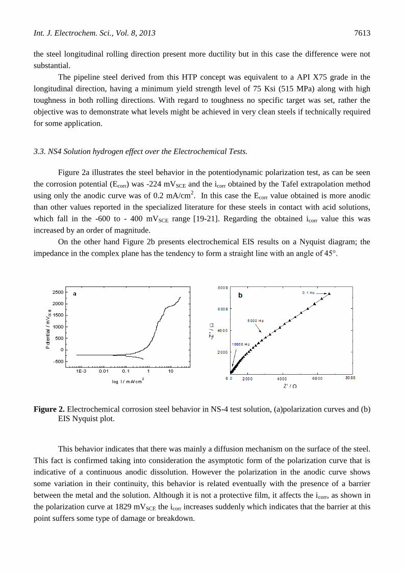
Figure 2a illustrates the steel behavior in the potentiodynamic polarization test, as can be seen
the corrosion potential (Ecorr) was -224 mVSCE and the icorr obtained by the Tafel extrapolation method
using only the anodic curve was of 0.2 mA/cm2. In this case the Ecorr value obtained is more anodic
than other values reported in the specialized literature for these steels in contact with acid solutions,
which fall in the -600 to - 400 mVSCE range [19-21]. Regarding the obtained icorr value this was
increased by an order of magnitude.
On the other hand Figure 2b presents electrochemical EIS results on a Nyquist diagram; the
impedance in the complex plane has the tendency to form a straight line with an angle of 45°.
Figure 2. Electrochemical corrosion steel behavior in NS-4 test solution, (a)polarization curves and (b)
EIS Nyquist plot.
This behavior indicates that there was mainly a diffusion mechanism on the surface of the steel.
This fact is confirmed taking into consideration the asymptotic form of the polarization curve that is
indicative of a continuous anodic dissolution. However the polarization in the anodic curve shows
some variation in their continuity, this behavior is related eventually with the presence of a barrier
between the metal and the solution. Although it is not a protective film, it affects the icorr, as shown in
the polarization curve at 1829 mVSCE the icorr increases suddenly which indicates that the barrier at this
point suffers some type of damage or breakdown.

Int. J. Electrochem. Sci., Vol. 8, 2013
7614
The potentiodynamic polarization curves of the steel in the test solution at slow and fast sweep
rate are shown in Fig. 3. With the NS-4 solution, polarization curves at different potential sweep rates
could show an active-passive transition over certain potential ranges, such transitions having been
shown to be associated with SCC of ferritic steels. The location of that peak on the potential scale
approximates to that in which cracking occurs, the indication of high anodic activity pointing to the
formation of soluble corrosion products, while the current decay in the same region of potential is
related with a film formation and thickening. SCC has correlation with pitting corrosion at initiation
stage. The initiation of SCC and pitting is the result of the instability of the passive film. The technique
was first proposed by Parkins [22] and can be used to forecast the different electrochemical process
between non-crack tip area and the crack tip. First, the sample was polarized anodically at a fast scan
rate of 10mV/s and then at a lower scanning rate of 0.1mV/s. The fast scan represents the behavior at
crack tip, while the slow scan represents the behavior of side wall. At fast scan rate the steel has no
sufficient time to reach a passive state, while at slow scan rate the steel could be passivated generating
a corrosion film over its surface. The potential range where the fast and slow scan rate polarization
curves exhibit large differences in current was identified as the SCC sensitive range [1]. As shown in
Figure 3 for the fast and slow potential sweep rate curves of the steel in NS-4 solution the predictive
potential range for SCC can occur is of 200 to -200mVAg/AgCl. (The -6mV difference in half-cell
potential electrode in comparison with SCE, is not significant in present results analysis).
Figure 3. Microalloyed steel slow and fast sweep rates under NS-4 solution
However, for clarifying and study the SCC behavior susceptibility of steel microstructure under
different conditions, different applied polarization potentials were plotted in Fig. 4. Each applied
potential is corresponding to different electrochemical process according to both slow and fast rate
sweep curves. For instance -600 mVAg/AgCl is in the range of anodic reactions of both slow and fast rate
sweep curves and -820 mVAg/AgCl are both in the cathode range. For this Figure “if” and “is” are
defined as fast and slow sweep current density respectively, and (if - is)/is was a normalized parameter

Int. J. Electrochem. Sci., Vol. 8, 2013
7615
used to investigate SCC susceptibilities of the steel microstructure under the NS4 solution according to
Parkins theory [22].
According to the results in Fig.4, (if -is)/is steel values at different potentials in the NS-4
solution conform approximately to a same tendence, with a difference that the value at -600 mVAg/AgCl
was higher than that of the other potentials. The values of (if-is)/is indicate that the electrochemical
processes over steel surface were different at each polarization potential. Three points of interest can
be related with crack tip and side wall processes. At -400 mVAg/AgCl the value sign is positive but very
close to zero, meaning that there is difference between crack tip and non crack-tip but both
electrochemical processes are anodic [3]. When the potential is -600 mVAg/AgCl reaches the higher
positive value, meaning that the electrochemical reactions both inside and outside the crack tip are
anodic too. At last when -820 mVAg/AgCl is reached the value was positive and close to cero again, here
the potential is in the cathodic side of the polarization curves. This can be due to that the
electrochemistry is opposite in the crack tip and outside the crack, being the anode the crack tip and the
cathode the side wall of the crack. So, it can be assumed that SCC mechanism of the steel in the NS-4
solution is anodic dissolution at -400 and -600 mVAg/AgCl, and a combination of anodic dissolution and
hydrogen embrittlement at -820 mVAg/AgCl, mostly hydrogen embrittlement. The susceptibility of the
steel to hydrogen steel could be explained as their microstructure as shown before was principally by a
very fine acicular ferrite and small patches of bainite and martensite, which results in good toughness-
high strength steel. As it well established as a rule of thumb that this kind of steels tend to be attacked
by hydrogen embrittlement [23]. For this reason the original microstructure is prone to SCC as the
applied potential drops from -600 to -820 mVAg/AgCl.
Figure 4. (if-is)/is values from the slow and fast sweep rates related to different polarization curves
potentials
The source of hydrogen comes as a sub product due to the corrosion effect of solutions over
steel crack tip or side wall crack tip. In the NS-4 solution the following ions could be present: HCO3-
,

Int. J. Electrochem. Sci., Vol. 8, 2013
7616
H2CO3 and H+ all of these ions are important to SCC and hydrogen embrittlement according to
literature [24]. H2CO3 comes from HCO
3- in acid environment. The NS-4 solution was oxygen free, so
oxygen depolarization can be ignored and the electrochemical process could be described as follows:
2H+ + Fe → Fe
2+ + 2H + 2e (1)
H2CO3 + e → HCO3-
+ H (2)
HCO-3 + e → CO
2-3 + H (3)
These three process all proceed when pH<7, when -820 mVAg/agCl is reached the cathode
process is mainly de-oxidation of H+ ion introduced by H2CO3 and HCO
-3. The hydrogen proton (H
+)
reduction process form atomic hydrogen (H) and speed-up hydrogen diffusion into steel matrix and
micro crack sites. This can lead to localized hydrogen embrittlement in crack tip zones that will
increase the steel susceptibility to fast rupture and cleavage fracture [25].
3.4. SSR Test
As seen in preceding sections, the steel has good mechanical properties comparable to a high
strenght steel although a HTP process combined with accelerated cooling was involucrated to fabricate
the microalloyed steel sheets. This processes can possibly leads to a steel microstructure susceptible to
hydrogen embrittlement, and the test solution (NS-4 solution at a 6.7 pH) can evolve sufficient
hydrogen to achieve the fragile cracking process as seen by analyzing Figures 3 and 4 data. On the
other hand SCC by anodic process also can be present as showed by the slow and fast scan rates on
Figure 3. However, to really elucidate the susceptibility of the microalloyed steels to SCC or Hydrogen
embritllement in the presence of tensile stress, Slow Strain Rate test were carried out. As an attempt to
simulate pipeline steel coating disbonding and rupture that is reported to form long wrinkles filled with
ground water leading to severe solution conditions [26], some tensile samples were cathodically
precharged with hydrogen and then tested with the NS-4 test solution. The test of the solely sample
cathodicaly charged with hydrogen and then tested in air was maid for comparison to the samples
charged with hydrogen and exposed to the NS-4 solution. The latter environment condition could
match the conditions of the steel at -820Ag/AgCl as indicated in Figures 3 and 4 .
The effect of the hydrogen and the NS-4 solution on the reduction of area in SSRT testing is
shown in Figure 5. The test conducted just in air (Air condition in Figure 5) serve as a reference area
reduction parameter, which shows that the steel longitudinal and transversal to the rolling direction
respectively, presented a ductile fracture. Under this conditions the area reduction is greater for the
steel longitudinal rolling direction. This behavior was expected due to the more elongation value
presented by the steel in this rolling direction. This means that although the strain rate is considerably
less than for a conventional tensile test, the stress-strain curve shape is very similar for both tests:
SSRT and conventional tensile test.

Int. J. Electrochem. Sci., Vol. 8, 2013
7617
Figure 5. Steel performance under SSR test under different experimental conditions: Air, Air-H, NS4
and NS4-H.
In the hydrogen pre-charged tests (designated as Air-H in Figure 5) it can be seen that in both
rolling directions a ductile fracture were evident with practical not cleavage fracture appearance as
shown in Figure 6. However, in the longitudinal direction the steel was more susceptible to hydrogen
embrittlement presenting a less area reduction.
Figure 6. SSRT steel longitudinal specimens hydrogen precharged and fractured in air.
The hydrogen steel embrittlement could be due to small hydrogen quantities trapped in grain
boundaries forming blisters. Some evidence of this embrittlement is shown in the steel fracture surface
on Figure 6 where voids at grain boundaries and plastic deformation coexists. On the other hand in the

Int. J. Electrochem. Sci., Vol. 8, 2013
7618
transversal rolling direction steel presented a slightly higher area reduction with respect the just in air
reference tests indicating less suceptibility to hydrogen embrittlement. In addition the steel yield
strength is lower (see Table 1) in the transversal rolling direction, which would eventually contribute
to the less hydrogen effects in this rolling direction. Also in Figure 6 is observed in the right side insert
the profile of one fractured part of the SSR steel test sample. It is shown at their tip a considerable area
reduction as a consequence of the ductile behavior of the steel in the form of a cup. This test specimen
profile is common to the longitudinal and transversal steel rolling direction tested either in air and with
hydrogen precharging. So, as mentioned before, this steel is particularly resistent to hydrogen
precharged effects.
Figure 5 shows that for steel in both rolling directions in the NS-4 solution the area reduction
was significantly lower than in the previous conditions, with 15.3 and 22.4 % area reduction values for
the steel longitudinal and transversal rolling direction respectively. In the rectangular left insert of
Figure 7 is shown the inferior end of a fractured SSRT steel transversal specimen in the NS-4 solution,
showing some necking. However, the fracture profile tend to form a 45 ° line with respect to stress
application.
Figure 7. Steel SSRT transversal specimen fractured in NS-4 solution
The fracture surface, illustrated in the central part and right side insert of Figure 7, shows brittle
fracture (cleavage planes) only at the border of the circular fractured sample indicated by the arrows.
Also was appreciated in the right insert the coexistence of intergranular voids produced by hydrogen
blisters.
On the other hand, there is no appreciable necking in the fractured steel longitudinal test
specimens tested in the NS-4 solution, as shown in the left upper corner insert in Figure 8. There is
only an 45 °angle with respect to the stress implementation. The fracture surface shows transgranular

Int. J. Electrochem. Sci., Vol. 8, 2013
7619
cracks ( left bottom and right inserts of Figure 8) located in the specimen fracture circular perimeter
with lengths between 20 to 80 μm without visible inside corrosion products.
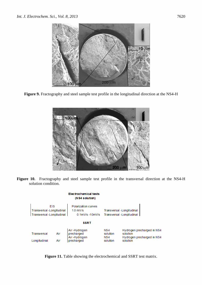
The SSRT steel logitudinal specimens precharged with hydrogen and exposed to NS-4 solution
(NS4-H condition) shows a area reduction value with brittle fracture in the longitudinal direction of
15.3 % as seen in Figure 5. This value is equal to that obtained in the steel specimen in NS-4 solution
without hydrogen precharge. However, the fracture surfaces of the steel specimens in the NS4-H
solution exhibit two types of secondary cracks at their periphery (Figure 9).
Figure 8. Steel SSRT longitudinal specimen fractured in NS-4 solution
The first type are relatively large transgranular cracks without inner corrosion products as
shown in the left box insert in Figure 9. The second type is related to lesser intergranular cracks with
10μm sizes, as shown by the ponting up arrow in the right bottom box insert of Figure 9. Also, there
are signs of cleavage indicated by the pointing down arrow, and the profile of the fractured steel
specimen (upper right box insert) presents a 45 ° pattern with respect to the tensile load application.
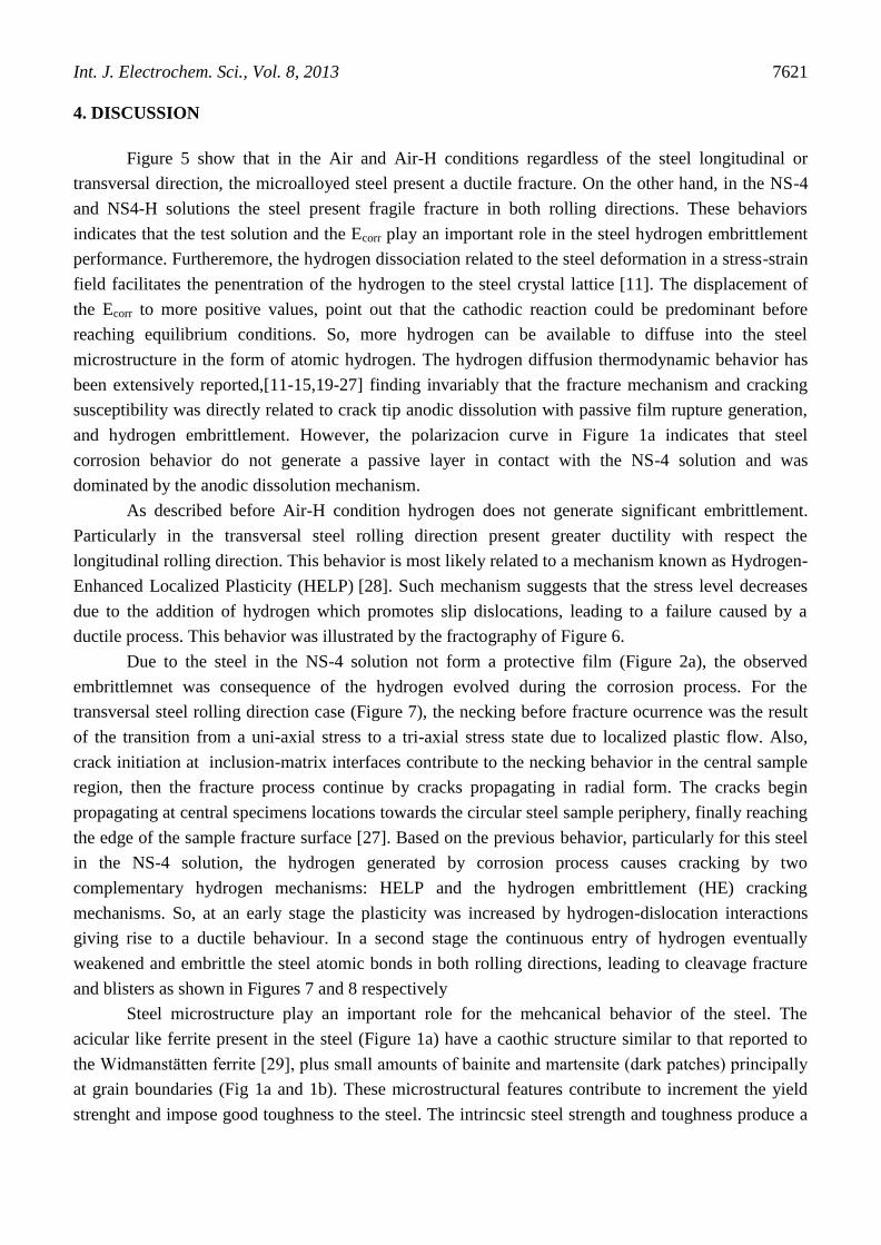
For the transversal steel rolling direction in NS4-H SSR tests, the behavior was quite different.
The area reduction was insignificant, presenting a completely fragile fracture, with
transgranular cracks in the sample periphery of the order of 200 μm, without the presence of corrosion
products in its interior (right box insert in Figure 10). Cleavage planes were evident as indicated by the
arrow in the left insert box (Figure 10). The steel sample test fractured profile (upper right insert on
Figure 10) shows the same pattern as in previous cases of 45 ° with respect to the tensile load
application.
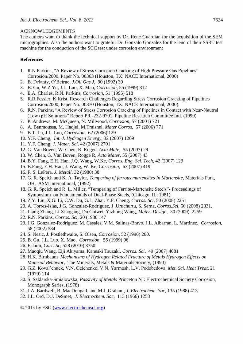
On Figure 11 it shows a table with the electrochemical and SSRT test matrix.
Int. J. Electrochem. Sci., Vol. 8, 2013
7620
Figure 9. Fractography and steel sample test profile in the longitudinal direction at the NS4-H
Figure 10. Fractography and steel sample test profile in the transversal direction at the NS4-H
solution condition.
Figure 11. Table showing the electrochemical and SSRT test matrix.
Int. J. Electrochem. Sci., Vol. 8, 2013
7621
4. DISCUSSION
Figure 5 show that in the Air and Air-H conditions regardless of the steel longitudinal or
transversal direction, the microalloyed steel present a ductile fracture. On the other hand, in the NS-4
and NS4-H solutions the steel present fragile fracture in both rolling directions. These behaviors
indicates that the test solution and the Ecorr play an important role in the steel hydrogen embrittlement
performance. Furtheremore, the hydrogen dissociation related to the steel deformation in a stress-strain
field facilitates the penentration of the hydrogen to the steel crystal lattice [11]. The displacement of
the Ecorr to more positive values, point out that the cathodic reaction could be predominant before
reaching equilibrium conditions. So, more hydrogen can be available to diffuse into the steel
microstructure in the form of atomic hydrogen. The hydrogen diffusion thermodynamic behavior has
been extensively reported,[11-15,19-27] finding invariably that the fracture mechanism and cracking
susceptibility was directly related to crack tip anodic dissolution with passive film rupture generation,
and hydrogen embrittlement. However, the polarizacion curve in Figure 1a indicates that steel
corrosion behavior do not generate a passive layer in contact with the NS-4 solution and was
dominated by the anodic dissolution mechanism.
As described before Air-H condition hydrogen does not generate significant embrittlement.
Particularly in the transversal steel rolling direction present greater ductility with respect the
longitudinal rolling direction. This behavior is most likely related to a mechanism known as Hydrogen-
Enhanced Localized Plasticity (HELP) [28]. Such mechanism suggests that the stress level decreases
due to the addition of hydrogen which promotes slip dislocations, leading to a failure caused by a
ductile process. This behavior was illustrated by the fractography of Figure 6.
Due to the steel in the NS-4 solution not form a protective film (Figure 2a), the observed
embrittlemnet was consequence of the hydrogen evolved during the corrosion process. For the
transversal steel rolling direction case (Figure 7), the necking before fracture ocurrence was the result
of the transition from a uni-axial stress to a tri-axial stress state due to localized plastic flow. Also,
crack initiation at inclusion-matrix interfaces contribute to the necking behavior in the central sample
region, then the fracture process continue by cracks propagating in radial form. The cracks begin
propagating at central specimens locations towards the circular steel sample periphery, finally reaching
the edge of the sample fracture surface [27]. Based on the previous behavior, particularly for this steel
in the NS-4 solution, the hydrogen generated by corrosion process causes cracking by two
complementary hydrogen mechanisms: HELP and the hydrogen embrittlement (HE) cracking
mechanisms. So, at an early stage the plasticity was increased by hydrogen-dislocation interactions
giving rise to a ductile behaviour. In a second stage the continuous entry of hydrogen eventually
weakened and embrittle the steel atomic bonds in both rolling directions, leading to cleavage fracture
and blisters as shown in Figures 7 and 8 respectively
Steel microstructure play an important role for the mehcanical behavior of the steel. The
acicular like ferrite present in the steel (Figure 1a) have a caothic structure similar to that reported to
the Widmanstätten ferrite [29], plus small amounts of bainite and martensite (dark patches) principally
at grain boundaries (Fig 1a and 1b). These microstructural features contribute to increment the yield
strenght and impose good toughness to the steel. The intrincsic steel strength and toughness produce a

Int. J. Electrochem. Sci., Vol. 8, 2013
7622
vast strain field when a high stress is applied in both rolling directions as was the case in the SSR tests.
This strain field seems to facilitate the hydrogen entry to the deformed steel lattice, making the steel
more susceptible to hydrogen effects under the test environments assesed.
Respect to the corrosion steel behavior is well known that for pure iron a -Fe2O3 film is the
responsible to the steel passivation [30-32], while a Fe3O4 layer promotes an oxidation state over the
steel surface. Thus, the Fe3O4 layer don’t contributes to disminish the steel anodic dissolution current.
In addition, to get a real steel surface passivation state, first has to be formed a Fe3O4 corrosion
products deposit, which in turn has a low oxidation state and is highly susceptible to chemical
dissolution. That's why until the conditions necessary for the formation and relatively stabilization of
this layer (Fe3O4) was present, the -Fe2O3s protective film could not be formed and the dissolution of
the steel will continue as observed in Figure 2a. Particularly in this study, the displacement of the steel
Ecorr to more anodic values could be related to the previous mentioned corrosion mechanism. This
statement could be explained on the characteristics of the acicular ferrite structure, in which the rapid
cooling from high temperatures led to a ferrite chaotic growth with a needle like form pointing to
random directions. This growth leads sharp elongated grains nucleating inside prior austenite grains
(figure 1a). This type of ferrite microstructure tends to create galvanic couples with inclusions and
precipitates rounding them that could slow down the ferrite corrosion rate, limiting the Fe3O4
formation and stabilization promoting the continuous corrosion of the steel. The grain boundary
martensite and bainite present in the steel could enhance this behavior acting as more active anodic
zones, restricting more the ferrite corrosion rate.
Higher steels grades, with more strength levels, are more susceptible to hydrogen
embrittlement. This statement is in accordance with this study, being the steel longitudinal rolling
direction more susceptible to cracking and hydrogen embrittlement than the transveral rolling
direction, as shown in Figure 5. As illustrated before in Table 1 the steel longitudinal rolling direction
has the better mechanical properties, thus applying higher stresses to the SSRT speciemens major
strain field zones could be produced. These deformed zones promote the hydrogen entrance and
interaction with the steel lattice and related defects as dislocations.
For the NS4-H the area reduction for the steel SSRT samples in the transversal direction was
bigger than in the lonely NS-4 solution condition (without hydrogen precharge). The presence of
transgranular cracks was evident in their fracture surfaces (Figure 10) without corrosion prouducts
inside the cracks. This cracks apparently grow from the SSRT center specimen to their circular border.
Theoretically, crack initiation could occur at any weak point since the given conditions of hydrogen
precharge and diffusion were uniform along the radial direction of the SSRT steel samples. However,
Figure 10 shows a linear and parallel crack growth pattern in the steel SSRT smaple surface. This
seems to indicate that fracture initiation, specifically in this steel with given conditions, was in the
center of the samples. The beginning of the specimen fracture at the center could be acomplished by
slip–microstructure interactions due to the combination of two hydrogen mechanisms like HELP and
hidrogen decohesion.These mechanisms seems to operate in hydrogen concentration zones like
dislocations, inclusions-matrix intefaces, and grain boundaries known to be strong hydrogen trapping
sites.

Int. J. Electrochem. Sci., Vol. 8, 2013
7623
Finally in the steel longitudinal rolling direction, the area reduction remained unchanged with
respect to the test without hydrogen preload, presenting transgranular cracks with the same pattern as
in the steel transversal rolling direction (Figure 9). However, the presence of intergranular small cracks
suggest that during the hydrogen difussion some remains trapped in grain boundaries with the absence
of inside cracks corrosion products. The steel in its longitudinal rolling direction microstrucutre
present more slightly elongated grains, with a extended area related to their grain boundaries. These
grain boundaries being high energy sites have a greater affinity for hydrogen trapping, leading to a
reduction in transgranular hydrogen blisters that eventually decreased its cracking susceptibility,
compared to the steel transversal rolling direction cracking susceptibility.
5. CONCLUSIONS
The microalloyed steel under study mainly presents a ferritic microstructure with various
morphologies (aciular, polygon etc.) and to a lesser extent bainite and martensite in grain boundaries.
This microstructure was the result of hot controlled rolling designated as “High Temperature
Processing" (HTP) and accelerated cooling, which gives the microalloyed steel plate different
mechanical properties with respect to their rolling directions. The steel in its longitudinal rolling
direction enclose better mechanical properties, mainly with respect to its yield strenght, UTS and
Young Modulus.
SSRT testing in both steel rolling directions shows that the microalloyed steel is susceptible to
interact with the hydrogen, either pre-charged or produced by corrosion in the NS-4 solution, and their
combination identified as NS4-H condition (hydrogen pre-charged + NS-4 solution). The latter
condition simulates the hydrogen that can enter to the steel being cathodically protected where the
protective steel coating has suffered a rupture. Microalloyed steel was susceptible in both rolling
directions to SCC in NS-4 solution mainly by anodic dissolution and hydrogen embrittlement
mechanisms, with the possible presence of the HELP mechanism too. The NS4-H test condition shows
the same mechanisms but hydrogen embrittlement was increased, this was noted by the minor area
reductions in the steel SSRT samples in both rolling directions.
The Ecorr in the particular case of this steel under the solution conditions assessed was more
anodic with regard to that reported in the literature. This result suggest that this behavior is closely
related to the coexistence of different ferrite morphologies in the steel mainly related to the acicular
ferrite with bainite and martensite patches at grain boundaries. This type of ferrite microstructure tends
to create galvanic couples with inclusions and precipitates rounding them that could slow down the
ferrite corrosion rate. Thus, limiting the formation and stabilization of the Fe3O4 leading to the
continuous corrosion of the steel. The grain boundary martensite and bainite present in the steel could
enhance this behavior acting as more active anodic zones, restricting more the ferrite corrosion rate.
It was also determined that this microstructure promotes a synergistic relationship between the
hydrogen diffusion in the steel and their mechanical properties reduction. This was especially
enhanced with respect to steel ductility loose indicated by their area reduction parameter in the NS-4
and NS4-H testing conditions, and the presence of cleavage characteristics in their fracture surfaces.
Int. J. Electrochem. Sci., Vol. 8, 2013
7624
ACKNOWLEDGEMENTS
The authors want to thank the technical support by Dr. Rene Guardian for the acquisition of the SEM
micrographies. Also the authors want to grateful Dr. Gonzalo Gonzalez for the lend of their SSRT test
machine for the conduction of the SCC test under corrosion environment
References
1. R.N.Parkins, “A Review of Stress Corrosion Cracking of High Pressure Gas Pipelines”
Corrosion/2000, Paper No. 00363 (Houston, TX: NACE International, 2000)
2. B. Delanty, O’Beirne, J.Oil Gas J, 90 (1992) 39
3. B. Gu, W.Z.Yu, J.L. Luo, X. Mao, Corrosion, 55 (1999) 312
4. E.A. Charles, R.N. Parkins, Corrosion, 51 (1995) 518
5. R.R.Fessier, K.Krist, Research Challenges Regarding Stress Corrosion Cracking of Pipelines
Corrosion/2000, Paper No. 00370 (Houston, TX: NACE International, 2000).
6. R.N. Parkins, “A Review of Stress Corrosion Cracking of Pipelines in Contact with Near-Neutral
(Low) pH Solutions” Report PR -232-9701, Pipeline Research Committee Intl. (1999)
7. P. Andrews, M. McQueen, N. Millwood, Corrosion, 57 (2001) 721
8. A. Benmoussa, M. Hadjel, M.Traisnel, Mater Corros, 57 (2006) 771
9. B.T. Lu, J.L. Luo, Corrosion, 62 (2006) 129
10. Y.F. Cheng, Int. J. Hydrogen Energy, 32 (2007) 1269
11. Y.F. Cheng, J. Mater. Sci. 42 (2007) 2701
12. G. Van Boven, W. Chen, R. Rogge, Acta Mate,. 55 (2007) 29
13. W. Chen, G. Van Boven, Rogge R, Acta Mater, 55 (2007) 43
14. B.Y. Fang, E.H. Han, J.Q. Wang, W.Ke, Corros. Eng. Sci. Tech, 42 (2007) 123
15. B.Fang, E.H. Han, J. Wang, W. Ke, Corrosion, 63 (2007) 419
16. F. S. LePera, J. Metall, 32 (1980) 38
17. G. R. Speich and K. A. Taylor, Tempering of ferrous martensites In Martensite, Materials Park,
OH, ASM International, (1992)
18. G. R. Speich and R. L. Miller, “Tempering of Ferrite-Martensite Steels”- Proceedings of
Symposium on Fundamentals of Dual-Phase Steels, (Chicago, IL; 1981)
19. Z.Y. Liu, X.G. Li, C.W. Du, G.L. Zhai, Y.F. Cheng, Corros. Sci, 50 (2008) 2251
20. A. Torres-Islas, J.G. Gonzalez-Rodriguez, J .Uruchurtu, S. Serna, Corros.Sci, 50 (2008) 2831.
21. Liang Zhang, Li Xiaogang, Du Cuiwei, Yizhong Wang, Mater. Design, 30 (2009) 2259
22. R.N. Parkins, Corros. Sci, 20 (1980 147
23. J.G. Gonzalez-Rodriguez, M. Casales, V.M. Salinas-Bravo, J.L. Albarran, L. Martinez, Corrosion,
58 (2002) 584
24. S. Nesic, J. Postlethwaite, S. Olsen, Corrosion, 52 (1996) 280.
25. B. Gu, J.L. Luo, X. Mao, Corrosion, 55 (1999) 96
26. Eslami, Corr. Sc, 528 (2010) 3750
27. Maoqiu Wang, Eiji Akiyama, Kaneaki Tsuzaki, Corros. Sci, 49 (2007) 4081
28. H.K. Birnbaum Mechanisms of Hydrogen Related Fracture of Metals Hydrogen Effects on
Material Behavior, The Minerals, Metals & Materials Society, (1990)
29. G.Z. Koval’chuck, V.N. Geichenko, V.N. Yarmosh, L.V. Podobedova, Met. Sci. Heat Treat, 21
(1979) 114
30. S. Szklarska-Smialowska, Passivity of Metals Princeton NJ: Electrochemical Society Corrosion,
Monograph Series, (1978)
31. J.A. Bardwell, B. MacDougall, and M.J. Graham, J. Electrochem. Soc, 135 (1988) 413
32. J.L. Ord, D.J. DeSmet, J. Electrochem. Soc, 113 (1966) 1258
© 2013 by ESG (www.electrochemsci.org)