hydrodynamic lubrication in cold rolling …...hydrodynamic lubrication in cold rolling a. g....
TRANSCRIPT

Int. J. mech. 8c/. Pergamon Press. 1974. Vol. 16, pp. 1-19. Printed in Great Britain
HYDRODYNAMIC LUBRICATION IN COLD ROLLING
A. G. ATKINS* Department of Mechanical Engineering, University of Michigan, Ann Arbor, U.S.A.
(Received 7 September 1972, and in revised form 4 May 1973)
S, ,mmary--Part icular at tent ion has been paid to the effects of roll flattening and to the inlet zone of pressure build-up in the determination of lubricant film thickness in cold rolling. I t is shown that under present-day practical conditions, the thicknesses of the lubricant films relative to surface roughnesses are insufficient to maintain full fluid film lubrication.
Although the mathematical model predicts a "speed effect" for rolling (plots of rolling load against speed looking like a Sommerfeld diagram for a journal bearing), the speeds involved are much faster than present commercial rates. Thus speed effects in the literature must have been caused by a change over from boundary to mixed lubrication and lubricant puddle entrapment in surface microcrevices. The non-dimensional form of the solutions shows that laboratory experiments rarely approach full-scale mill conditions, thus reflecting the notoriously difficult problem of evaluating commercial metal-working lubricants.
NOTATION
Upper case letters refer to non-dimensionalized quantities expressed by equivalent lower case letters, where relevant.
c~ specific heat of strip D undeformed roll diameter E Young's modulus of rolls
f(x), F(X) location of undeformed roll h(x), H(X) film thicknesses
J mechanical equivalent of heat k shear yield stress of strip
p(x), P(X) roll pressure distributions Q lubricant flow rate R undeformed roll radius r reduction in pass (%)
A non-dlmensional limit of plastic zone t(x), T(X) strip thickness
T temperature (non-dimensionalized as 8) U speed
v(x), V(X) elastic deformation of rolls x, X coordinate along arc of contact
Z dummy variable a, & viscosity pressure coefficients /~, # viscosity temperature coefficients
~7 viscosity W = ~?0 exp (~_P-/~8,) 8~ non-dimensional mean temperature across film K I thermal conductivity of lubricating fluid
i z coefficient of friction v Poisson's ratio p density a strip tension
v(x), 3-(X) shear stress
* Formerly Department of Engineering Science, University of Oxford. l 1
2 A.G. ATKINS
Su~xes 0 exi t f rom plast ic zone 2 lubr icant A en t ry to plast ic zone 3 str ip 1 workrol l N neut ra l po in t
Quant i t ies are normal i zed as fo l lows:
X = x/fo, F = f / fo , H = h/fo, T = t/fo, V = v/fo, p = p/2k, sr = ~ / 2 k . O = ~ / ~ , ~ b ~ . ~ t . ~ = ~'2k, ~ = M'~b~,.t.
The fo l lowing non . d imens iona l groups are o f impor tance:
¢ = / o / R , E * = (1-v~)2]¢ W* = (1+v)2/¢ 7rE ' 1rE
~/o U1 7/o U~ 2]c = 2kfo Q" = jKt~ambten t Qs ~ j p c ~ a m b l e n t
A l s o
J o
l ~A/o
= 2/cfoJ ° p d x .
MODELS FOR HYDRODYNAMIC LUBRICATION IN ROLLING
THE PR~CmE mechanism of lubrication in cold rolling and other forming processes is a contentious matter. The well-known "speed effect" with wet lubricants indicates some form of hydrodynamic lubrication, 1, 2 yet the highly burnished rolled strip that can be produced with " thin" lubricating otis suggests metal-to-metal contact. Knowledge of the conditions under which full fluid film lubrication may occur is important for many reasons, not least of which is choice of metal-forming lubricant, i.e. whether the chemical properties should be of primary concern (for the boundary lubrication end of the spectrum) or whether the bulk viscosity properties should be of major importance (for hydrodynamic lubrication). At present, the selection and development of appropriate lubricants seems to be a branch of witchcraft!
Table 1 summarizes the mathematical solutions a-l° of varying degrees of complexity that have been presented for cold rolling with hydrodynamic lubrication. Similar work has been performed for drawing and hydrostatic extrusion.11,19 Other au thors) °, ~1 although not giving mathematical analyses, have discussed hydrodynamic effects in cold rolling. The mathematical models assume smooth contours for roll and strip, or die and workpiece, with no consideration of local surface irregularities. When the predicted film thicknesses are too thin to prevent asperity contact, the solutions are invalid. The conditions surrounding film breakdown set bounds on the possibility of full hydrodynamic lubrication.
Elastohydrodynamic (e.h.d.) gear theory indicates that lubricant flow in the inlet region of pressure build-up must determine the film thickness in the roll gap where the plastic deformation takes place. Most of the analyses in Table 1 concentrate merely on the zone of plastic deformation, with no consideration of pressure build-up and fall-off; the film thicknesses that are used are either

"iI 0
0
( 0
II
H y d r o d y n a m i c lubr ica t ion in co ld rol l ing
0 0 N N
i i
I A
v
O ~e~
II II II II
A
I
II II
~ ~o
0
_Q
0
II
0
.3
0
0
t$

4 A. (]. ATKINS
inserted into the analyses from independent e.h.d, gear formulae or are arrived at from energy considerations. Unless such film thicknesses can actually be generated in the entrance zone, the analyses are open to question. I t is desirable instead that film thicknesses be derived by application of Reynolds equation to the entrance zone; this has been done only in refs. (8) and (9).
Clearly the geometry of the entry region is all-important: indeed, for the hydrodynamically favourable case of high speed rolling of thin strip, the roll "flattening" can be greater than the thickness of the strip. Elastic deformations of the strip itself are small in comparison, so the inlet region geometry is affected predominantly by roll deformations. Although they took the entrance region into account, Wilson and Walowit ~ considered rigid rolls, and obtained some curious results, such as infinite rolling forces for some conditions. An important contribution from ref. 8, and one described in this paper below, is the inclusion of roll elasticity and its effect on film thicknesses generated in the entrance zone. Some interesting conclusions regarding the "modelling" of rolling tests can be deduced from the form of the solutions.
T H E P R E S E N T M O D E L
Fig. 1 depicts rolling with complete lubricant separation of roll and strip, where the rolls, the fluid and the strip arc called regions 1, 2 and 3. Unlike ref. (9) this work takes into account the elastic deformation of the rolls in determining film thicknesses from the geometry of the inlet region and from the overall compatible pressure distribution; in
Entry ~ E x i t
' i 0
r (x )~ " ~ iFCX~ \ I I - - v Elotter~edlroll I
Strip Original " ~ \ 1 ~ _ I u n d e f o r m e d roll ~ _ - ~ ~ J I
I - 2
1 . _ Rigid , ~ I Rig id
u3x FIG. 1. Schematic diagram of roll/fluid/strip geometry.
addition, a thermal analysis is incorporated for the zone of rigid-perfectly plastic defor- mation in the strip, but not for the inlet zone. Crook's experiments *~ showed that film thicknesses in e.h.d, were insensitive to the shear heating in the entry zone. Reference to Table 1 will show the contribution of the present model in comparison with previous studies. Because of the uncertainty of lubricant rheology in metal forming, Newtonian fluids have been assumed, but viscoelastic effects are briefly discussed later in the paper.
The assumptions of classical two-dimensional lubrication theory tha t are made for e.h.d, theory are well documented elsewhere. .3 l~eglect of Poiseuillo flow in comparison
Hydrodynamic lubrication in cold roiling 5
with Couette flow leads to a simple interrelation between fluid flow rate and strip mass flow rate [equation (8) in the Appendix]. However, this assumption cannot be used for the inlet and outlet regions and there the full Reynolds equations must be used. Since the fluid flow rate is continuous throughout all regions,
must be the same as
1 dp.3 /U1 +Ua\ q~n,~t = qo~,t~et = ----leV ~x ~ + ( - - 7 - - ) h
Qplasttezone=(Ul~U--a) h,
which forces zero pressure gradients at the end of the inlet zone of pressure build-up and at the beginning of the outlet zone of pressure fall-off. Since the pressure gradients in the plastic zone are often small, the discontinuity is not great, and it should be remembered anyway tha t the pressure gradients will not match at the zone boundaries when elastic deformations of the strip are neglected because of the resulting "kinks" in the strip edge profile. Again, since the film thickness and pressure at the end of the plastic zone pass over into Reynolds equation for the outlet region, the usually invoked criterion of
P = ~ x = 0
cannot be used to define the location of zero pressure downstream; rather the film break-up position follows directly from the equation.
The addition of elastic roll flattening to the rolling model poses problems which are not encountered in e.h.d, rolling theory. A place must be assigned where roll displacements are zero. For convenience the roll centres are chosen as fixed, and hence there appears an extra term in the Bonssinesq integral for the roll flattening. Secondly, the end of the zone of plastic deformation will not coincide with the line of centres of the rolls and extends to the exit side of the mill. This was found by Jor tner et al. 84 and it is strictly true when using Hitehcock's expressions, al The location of minimum film thickness is also altered, and Bloor et al. 18 noted similar effects in sheet drawing. I f deformation ends on the roll centrelines, the location of minimum strip thickness is clear, and an easy origin for coordinates in the roll bite presents itself. Wi th finite film thicknesses and elastic flatten- ing, plastic deformation does not end on the roll centrelines and computer "searching procedures" have to be used ~4 to locate the positions of minimum strip thickness and film thickness (which are not necessarily coincident). Some trial runs on the computer showed that the position of minimum thickness was extremely close to the roll centrelines for most geometries, and since the total program was already complicated and requiring a prohibitively long computer t ime it was decided to force the slope of the plastically deforming strip dT/dX to be zero at the line of centres. This located an origin for horizontal co-ordinates, and simplified computation without too much loss of accuracy; we should note tha t forcing d T / d X ---- 0 at X = 0 denies the possibility of finding any exit pressure spikes as are sometimes found in e.h.d, models. Finally, i t should be observed that the contribution of the inlet and outlet pressure " ta i ls" to the overall elastic roll flattening is neglected, so tha t the Boussinesq integration (for the whole flattening) is performed only upon the pressure over the plastic zone. Fig. 4 shows tha t it must always be in error, but mostly it is an adequate approximation which reduces computing time.
The problem was formulated in non-dimensional form since ad hoc solutions for given geometries of reduction fail to show an overall picture ; moreover, the method of presen- tat ion sheds light on problems of "modelling" rolling tests for evaluation of metal-forming lubricants. Nevertheless, the results are presented in a form that, it is hoped, will appeal to workers in the field of metalworking. For brevity, the equations for the different regions are given in their final form in the Appendix. Their derivations follow fairly obvious routes and may be found in detail in ref. (8), where also may be found the detailed computational procedures; a brief outline of the methods of solution is given in the Appendix.

6 A.G. ATKINS
R E S U L T S A N D C O M P A R I S O N W I T H O T H E R H Y D R O D Y N A M I C R O L L I N G M O D E L S
Pressure distributions, film thicknesses, rolling loads per uni t width etc. were obtained for many combinations of reductions, speeds and strip/roll geometries. Ranges for the values of the non-dimensional parameters in the model were based upon typical rolling conditions as follows:
1 i n . < D < 2 1 in., 0.0005 in .< f0<0 .10 in . ,
1 f t /min (laboratory) < U 1 < 6000 ft /min (factory),
5000 lbf/in 2 < 2k < 120,000 lbf/in 2, 7/o ~ 3 × 10 -s lbf-s/in 2,
a ~ 10 -4 in~/lbf, ~ ~ 0.028/°F, Kr ~ 0.082 BTU/hr- f t - °F .
I t is realized that the lubricant data are more applicable to gear oils (although the widely used cold-rolling lubricant palm oil does have comparable properties), but in the absence of such data for emulsifiable oils these values must suffice. Thus,
10-s < ~ < 10 -2,
1 0 . 6 < & < 10 -2,
3 x 10-a <Q,,, < 30,
0 . 5 < & < 15,
f] = 1.5,
E* = 2.86 x 10 -4,
W* = 4.14 x 10 -4,
Qs = 2 (steel); 3 (ahtminium).
In a physical sense, E* and W* are 'reduced' moduli of the workrolls; Q~ and Qs relate to the thermal conductivit~ of the lubricant and the heat capacity of the roiled material respectively; & and/~are the non-dimensional pressure and temperature viscosity exponents; f¢ is a modified Sommerfeld number and ¢ is a measure of roll gap geometry. Thus solutions for reductions, speeds and strip/roll geometries involved varying T~, if, ~.
(a) F i l m thicknesaes
These followed a sensible pattern, so that where roll flattening was allowed for, the 61ms were thicker than those where rigid rolls were considered, and where the viscosity increased with pressure, thicker films were predicted over the corresponding isoviscous cases. For example, the differences in the non-dimensional film thicknesses for the set of plots in Fig. 2 are quite striking. They are (i) 5 × 10 -6 for rigid rolls and ~ constant, (ii) 2 × 10 -8 for rigid rolls and ~/ varying exponentially with pressure, (iii) 1 × 10 -4 for elastic rolls and 7/ constant, (iv) 5 x 10 -8 for elastic rolls and ~ varying with pressure. As soon as the viscosity increases with increasing pressure the predicted films thicken up, and with the augmentat ion of roll elasticity, the Aim thickness in case (iv) is one hundred times bigger than case (i). This is well established in e.h.d, gear theory. Greater plastic reductions in area generally had th inner films because of the geometry at entrance to the roll gap. Similarly, film thicknesses were greater at small ~ (i.e. large rolls and thin strip promote hydrodynamic films), and the films increased in thickness with speed of rolling. The curious effect predicted by Bedi and Hillier in refi (10), of film thicknesses decreasing with speed and then increasing, did not emerge from the solution.
For the range of cases considered (with elastically flattened rolls and pressure- and temperature-dependent viscosity), film thicknesses at entrance to the plastic zone were found by curve fitting to follow the approximate relationship
H = 0"4ff~-2/S{load + ~/o reduction} 1/10.
The ratio of {non-dimensional roll load/~/o reduction in area} remains essentially constant for given ~ because the "friction hills" are so small (el. following section, and the slopes of Figs. 5, 6 and 8). Strictly, of course, the expression is dependent on E* and W*, & and/~, Q~ and Qs, a0 and am, and T~. However, the above expression gives a good overall indication of the order of magnitude of the film thicknesses.
The absolute values are little smaller than those in Bloor et al. 18 for similar geometries but all are of the same order of magnitude as e.h.d, theory.

Hydrodynamic lubrication in cold rolling 7
The analysis allows for variations in film thickness throughout the roll bite. I t turns out, as may be anticipated from the high pressures involved, tha t the film is nearly constant in thickness over the plastically deforming zone; it does thin down towards the exit of the mill, bu t by no more than about 20 per cent.
Od
o. L~ m w 8.
8
| N eu'l'rol point : . . ~ ~ 1 . 4 (li) . (i)
I o-8 I~
i o6 I=
o-4 II Ii
o.2 I, . I
o 5 0 ~5 2b 2s
Exit Entry | I
Contac~ length, X= x#~ (a)
(ilR~d mils, 0,I0 isovlscous lubricant \ / ,
Y
0"0( (ii) Rigkl rolls, ~ . . . . . . pressure dipendem~'~/'" / .^,,..(iii) Flottenea mils;
~ _ . , " ~ . . . . . ~ J ~o " ~o 4o -O.02
(b) FIo. 2. (a) Pressure distributions over plastic zone for approximately 30 per cent reductions with zero entry and exit tensions. ~b = 10 -3, 9r -- 10-~. (i) Rigid rolls, isoviscous lubricant; (ii) rigid rolls, pressure- and temperature-dependent viscosity; (iii) flattened rolls, isoviscous lubricant; (iv) flattened rolls, pressure- and temperature-dependent viscosity. The friction h~lh are diminished to almost nothing when the lubricant viscosity changes with pressure and temperature, and when roll flattening is taken into account. The film thicknesses corres- pondingly increase markedly over the values for isoviscous lubricants and rigid rolls. (b) The distribution of the coefficient of friction through the plastic zone for the same four cases as Fig. 2(a). The shear stresses change direction on either side of the neutral point, which gives rise to
the apparently negative values for/~.
(b) Pres~rure plots and shear tractiona
The form of the computation (two-point boundary value problem) meant tha t the roll pressure at one end of the plastically deforming zone was specified and tha t at the other end came out as par t of the solution. Values between 0 and 1 for the dimensionless

A. G. ATKINS
pressures are acceptable, the quanti ty ( l - P ) indicating the appropriate entry or exit tensions (aa or a0) for the compatible pressure distribution.
Some typical pressure plots for the plastic zone which bring out the essential features of the process are shown in Figs. 2 and 3. The 'pairs' of results for rigid roils and flattened rolls show that roll elasticity produces shallow "friction hills", and that
. n.pt.
/ X - + = , o -° / / \
z I
Q.
g
z
0"4
I J J
20 4O 6b 80 10o rL, o
Ex i t Contact lengCh, )(=x/f o
Entry
FIG. 3. The effect of the geometric factor ~ (strip thickness/roll radius ratio) on the pressure distribution over the plastic zone. The percentage reduction in area is 33 per cent, ~ = 10 -4, and a 20 per cent exit tension, zero entry tension condition is assumed. Rigid rolls bring out the change in the friction hill more than flattened rolls. Small ¢ reduces the friction hill, but the overall rolling load is greater with smaller because of the increased arc contact length. The range of values for
/z also decreases with decreasing 4"
the friction hills are always greater when viscosity varies with pressure, although only marginally so in the roll flattened case. This suggests that roll geometry is more significant than pressure viscosity effects in determining pressure profiles and shear tractions, yet the film thicknesses seem more dependent on the viscosity than the geometry. Of the four plots of shear traction, only case (ii) looks anything like a Coulomb slipping friction model with equal values of/~ on either side of the neutral point. As predicted by equation (7) the neutral plane is always closer to the exit of the mill than the pressure maximum; in Coulomb models the pressure cusp and neutral point coincide. Fig. 3 shows tha t small reduces the magnitude of the friction hill, because of increased film thicknesses, but of course the overall rolling load is greater because of the greater contact length. A typical complete pressure sweep including inlet and outlet regions is shown in Fig. 4. The " ta i ls" to the curves, which are omitted in earlier figures, show characteristics similar to the entry and exit regions in e.h.d, roller theory, i.e. a long inlet sweep, and a fairly rapid fall-off at outlet.
To enable sensible overall comparisons to be made between various combinations of reductions, roll geometry, mill speeds, etc., an arbitrary "s tandard" case of rolling with zero entry tension and 20 per cent exit tension (P0 = 0.8) was chosen, and results are most readily presented in the form of force/reduction curves (familiar in the metal-forming literature) as functions of ~ and ~. The characteristic S shape is predicted quite well (Figs. 5 and 6), and the influence of the strip/roll geometry on the rolling loads is brought out. There is a gradual diminution in roll force as the speed is increased (i.e. as ~ is increased at constant ~ ). For • < 10-4 (when ~ = 10-~) and for ~ < 10-5 (when ~ ----- 5 × 10⁻⁵ ) the force.reduction curves are effectively identical and may be thought of as the "quasi- s tat ic" curves;* it seems that only when film thicknesses increase rapidly with ~ do the
• I t has been shown that strain-rate effects in high-speed rolling can affect the position of the force-reduction curves 87. This is not considered here.

H y d r o d y n a m i c l u b r i c a t i o n in cold rol l ing 9
I'0
ii
~Z o., °/ g
Exit Entry
Contoc'l" length/X~x/f
FzG. 4. A comple t e p ressu re sweep for a r ig id mi l l i nc lud ing t h e in le t zone a n d o u t l e t zone. T he p e r c e n t a g e r e d u c t i o n is 33 pe r cent , ~b -- 10 -8,
= 5 x 10 -3, a n d a 20 p e r cen t ex i t t ens ion , zero e n t r y t en s ion cond i t i on is a s sumed . T he r ig id rolls a c c e n t u a t e t h e f r ic t ion hil l so t h a t t h e zero slope p ressure d i s c o n t i n u i t y a t e n t r y to a n d ex i t f r om t h e p las t i c zone is s h o w n u p more t h a n would be t h e case w i t h t h e smal l f r ic t ion hills of f l a t t e n e d roll cases. T h e cond i t ions chosen for i l l u s t r a t i on also show t h a t t h e a reas u n d e r t h e in le t a n d o u t l e t p ressure zones a re n o t a lways negl ig ib le c o m p a r e d w i t h t h e a reas in t h e p las t i c zone alone.
2 2
2O
,8
16
' °
_ 6
4
o o
~,=l.5xlO "2 "2
.={ --J//I
I ! !
Red~-tion in omo, %
FzG. 5. N o n - d i m e n s i o n a l rol l ing l o a d / r e d u c t i o n cu rves for ~b = 10 -=. A t modi f ied S o m m e r f e l d n u m b e r s ~ < 10 -4 t h e cu rves co inc ide ; a t g r ea t e r
t h e ro l l ing loads d i m i n i s h for a g iven p e r c e n t a g e r educ t ion .

l0 A . G . ATKINS
curves separate. In the later Fig. 8, a trend of increasing loads at the highest speeds is shown; this is commented upon later.
~=5xlO -~
~ o ~ I~o "5 JSC
o
i g 50 Z
~=10-3
o ~ o Io 20 50 40 50 60
Reduction in area, %
FIG. 6. Non-dimensional rolling loacl/reduction curves for ¢ = 5 x 10 -5. For ~ < 10 -5 the curves bunch together, rolling loads dimims" hing at greater ~. The increases in rolling loads compared with those in Fig. 5 for the same percentage reductions arc due to the increased contact
lengths (augmented by roll flattening) at smaller ~.
(c) Comparison with other analyse~ Cheng a showed that large increases in the pressure-viscosity exponent produced large
increases in rolling load, and the theory of Wilson and Walowit 9 predicts infinite pressures in the work zone, especially at large reductions. This led them to suggest an upper limit on & (together with a lower limit when the rolls spin without performing any reduction). Excessively largo pressures are not seen here for comparable non-dimensional conditions because of the contribution of roll flattening in the present model (eL Fig. 2). Further proof tha t the large pressures arc due principally to the omission of roll elasticity is given in ref. 8. Furthermore, it seems significant tha t increases in rolling load at high speeds (Figs. 8 and 9 later) take place when the film thicknesses have become greater than the (reduced) elastic flattening. Clearly increasing ~ must generally increase rolling loads, but at the same time the effects of temperature in reducing ~? must not be forgotten. Consequently, the narrow "band" of acceptable values of & predicted by the isothermal, rigid roll analysis 9 may not be quite so severe and restricting.
D I S C U S S I O N
(a) Range of validity el solutions: thinnest and thickest films A thickness of less than some 10 -5 in. is probably not admissible for complete separation
of surfaces by a hydrodynamic ~lrn; asperity contact takes place if thinner Rlm~ are predicted. Most practical roll bites are in the range 0.070-0.001 in., so that for hmm,g 10 -5 in., H ~ 3 × 10-~N 10 -=. Perusal of the calculations indicates that for usual values of ~b and strip thickness, hydrodynamic lubrication is unlikely for ~ < 10 -5 with thick stock and ~ < 10 -3 with thin stock. A rough rule might be that fg must be greater
Hydrodynamic lubrication in cold rolling 11
than 10 -4 when ~ is in the range 10-2N 10 -a for full film lubrication to take place (see next section). I t may be observed that hydrodynamic conditions exist at low speeds only with thick strip, and that large roll radii promote full fluid iqlmR, SO that, qualitatively, frictional effects will decrease with increase of roll diameter as reported by Rober ts ."
The film thicknesses agree quite well with the figures tha t can be derived s from experimental determinations of "minimum oil-film weight" for rolling steel strip, given by Bentz and Somers." This must be viewed with caution, since it is unlikely tha t full fluid film lubrication was taking place in their experiments, as will be demonstrated in the next section.
Turbulent flow could set a limit on the upper range of admissible film thicknesses for the rolling problem. When Taylor's instabili ty criterion [e.g. ref. (27)] is applied to the rolling problem it is found that either, for a given speed, the film thicknesses at which turbulence would set in are much greater than the compatible hydrodynamic rolling film thicknesses or, equally, tha t for a given film thickness the speeds at which turbulence would be predicted are far in excess of the compatible hydrodynamic rolling model speeds. 8 Thus, this limiting effect need not concern us.
(b) Comparison with experiment, rolling loads and fr~tion I t is rarely possible to make direct quanti tat ive comparisons with previous experimental
rolling data, since little information is usually given concerning the mechanical properties of the rolling oils used, which causes difficulties in estimating parameters such as @.
22
o
14
r r -
: (Benzene : // lubricont)
Low speed i / experimen'l's"~ / ,~ igh speed
/ / i experiments
IC o 20 ~o
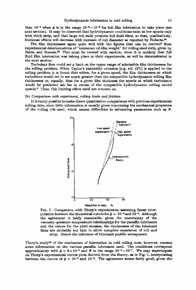
Reduction in area, % FIG. 7. Comparison with Thorp's experiments, assuming linear inter- polation between the theoretical curves for ~ -- 10 -s and 10 -8. Although the agreement is fairly reasonable, given the uncer ta inty of the viscosity-pressure--temperature relationships for the paraf l~ lubricants and the values for the yield stresses, the thicknesses of the lubricant films are probably too thin to allow complete separation of roll and
strip. Hence the inference of lubricant puddle entrapment.
Thorp's s tudy 3" of the mechanism of lubrication in cold rolling does, however, contain some information on the various parairm lubricants used. The conditions correspond approximately with ~ = 6 x 10 -3 and @ in the ra-ge 10 -3 N 10 -T. We may superimpose on Thorp's experimental curves plots derived from the theory, as in Fig. 7, interpolating between the curves of ~b - 10 -3 and 10 -3. The agreement seems fairly good, given the
12 A . G . ATKIN8
uncertainty of viscosity relationships and yield stresses. However, the curves are in the "s ta t ic" range of the analysis, and the theoretical hydrodynamic film thicknesses are "too th in" at the rolling speeds used in the experiments. As suggested by Thorp, oil entrapment in surface microcrevices is contributing to the apparent hydrodynamic behaviour. The mathematical model used here does not take into account the possibility of oil puddles.
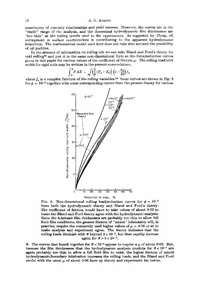
In the absence of information on rolling oils we can take Bland and Ford's theory fbr cold rolling 2~ and put it in the same non-dimensional faith as the force/reduction curves given in this paper for various values of the coefficient of friction/~. The rolling load/unit width for rigid rolls may be writ ten in the present nomenclature,
where f~ is a complex function of the rolling variables. 3° Some curves are shown in Fig. 8 for ¢ = 10 -8 together with some corresponding curves from the present theory for various
6 0
5 0
40
g
20 g m
t
¢=10 -3
fheory
./"07//
i/ 0 to 20 30 40 50 60 70
Reducfion in area, %
FIo. 8. Non-dimensional rolling load/reduction curves for ~b = 10 -3 from both the hydrodynamic theory and Bland and Ford 's theory. The coefficient of friction would have to take values of about 0.02 to make the Bland and Ford theory agree with the hydrodynamic analysis. Since the lubricant film thicknesses are probably too thin to allow full fluid film conditions, the greater friction of "mixed" lubrication will, in practice, require the commonly used higher values of F = 0.08 or so to make analysis and experiment agree. The theory indicates tha t the rolling loads diminish with ~ beyond 5 x 10 -s, but then rapidly increase
again for ~ > 5 x 10 -3.
~. The curves tha t bunch together for 9~< l0 -~ appear to require a/~ of about 0.02. But, because the film thicknesses that the hydrodynamic analysis predicts for 9~< 10 -4 are again probably too thin to allow a full fluid film to exist, the higher friction of mixed hydrodynamic/boundary lubrication increases the rolling loads, and the Bland and Ford model with the usual/~ of about 0.08 lines up theory and experiment far better.

Hydrodynamic lubrication in cold rolling 13
(c) Speed eJ]ec$ I t is instructive to plot rolling load vs speed for various reductions in area, Fig. 9.
For ¢ - 10 -3 a marked minimum is seen in the curves of roll load against speed at ~ 3 × 10 -3, and then the rolling load increase8 with speed. For ¢ = 10 -8, the curves are
still falling at ~ = 1 0 -~, though they are quite flat. The trend of results suggest a minimum in rolling load for ~b = 5 × 10 -5 at ~ ~ 10 -8 although the data for this ~ are insufficient to be precise. As remarked by Billigmarm and Pomp, 23 we are reminded of the Sommerfeld diagram for a journal bearing, where bearing friction is plotted against Sommerfeld
6 0 -
55% I
5 C -
4 5 % I , i
"o 4C i • *'- 35 % ~ /
o 3C
o .~_
E "io
o Z IC
~. I0-3
25%
55%
25%
I I I I t JO-6 jO-5 10"4 10-3 10"2 IO-I
Fro. 9. Non-dimensional rolling load vs. speed for various percentage reductions and various 4" A marked minimum in rolling load is seen at ~ = 5 x 1 0 -3 for ~ - - I0 -8. The curves of ~b= 10 -z may have a minimum about ~ -- 10 -~, and those for ¢ = 5 × 10 -6 (not plotted) may have a minimum at about ~ = 10 -8. There is an analogy with the Sommerfeld diagram for a journal bearing, where of course the minima are more marked than hydrodynamic theory suggests, because of the
high loads of mixed lubrication at low speeds.
number (effectively speed and load-carrying capacity); ~ is a modified Sommerfeld number. A minimum is predicted in tha t curve as is well known, with an increase in frictional drag subsequently as the speed increases. In practice the minimum is more marked than the theory suggests, since mixed or boundary lubrication takes over at speeds lower than the minimum. Compare, in subsection (a) earlier, the suggested values for • a t the threshold of full fluid film lubrication, based upon asperity heights.
Since rolling loads can increase at large ~, we should expect to see a "reverse" speed effect which should be more noticeable at small 4, where films are thickest. Bedi and Hillier ~ noted this possibility with their rigid workroll solution. The rolling speeds at which loads should start to increase (from ~ being about 10-4), say, are some 10,000 ft]min~ which are much greater than the fastest commercial speeds at present. The marked minima in rolling loads for ~ - 10 -3 in Fig. 9, at about ~ ~ 3 x 10 -8, correspond to roll speeds in excess of 100,000 ft /min!

14 A.G. ATKINS
The film thicknesses predicted by the present model for the conditions obtained in previous experimental studies of the speed effect 1, z, 20, 21 are extremely thin. Hence the observations of earlier workers probably reflect the changeover with speed from boundary lubrication into mixed lubrication, together with pseudo-hydrodynamic effects caused by puddle entrapment. All workers agree that the speed effect should be more noticeable at small ~; this is in accord with e.h.d, theory since small ~ encourage thick films, and qualitatively the strip exit thicknesses must diminish when film thicknesses increase with speed and when the roll flattening and mill spring decrease with the lower loads. Billigman and Pomp's factor (1/¢)~[r/(1-r)] suggests in addition that the speed effect is more noticeable the greater the percentage reduction in the pass. ~1 This is contrary to Ford 1 and the present theory (Fig. 9), but presumably is dependent on lubricant entrapment over long contact lengths. For reasons explained in the previous section, the experimental range of values for /~ associated with the speed effect [derived from Bland and Ford's theory in reL (20) or Ekelund's theory in ref. (21)] will be greater than the values from the present analysis. The suggestion 5, e that ~ ac ~¢t does not seem to be borne out.
(d) RoU flattening The effect is most pronounced at small ¢ and small ~. Some sample calculations for
= 10 -8 and ~ = 10 -3 show something like a 10 per cent increase in contact length over the equivalent rigid roll, isoviscous cases. Hitchcock 31 would predict a 30 per cent increase in roll radius and hence ~/(1"3)- 1 ~ 14 per cent increase in arc length. Even though the arc length calculations of Hitchcock seem similar, the lubricant thicknesses that are obtained by inserting a "flattened ~" in the equation for film thickness markedly under- estimate the actual thickness. Thus the overall roiling response, depending so much as it does on film thickness, would not be correct using I-Iitchcoek's expression. I t can be argued that, despite Bland's thorough analysis, aS the validity of using Hitchcock's flattened roll radius in roiling theories has never really been tested, since the elusive coefficient of friction in force-balance analyses is adjusted to make theory and experiment agree (cL Jortner et al.~4). I t can be pointed out again that the incorporation of roll flattening in the present analysis eliminates the difficulties encountered in ref. (9).
(e) "Modelling" rolling tests I t is notoriously difficult to evaluate and characterize lubricating oils for metal-forming
applications. Laboratory experiments performed on disc and ball machines do not always predict the performance of the same lubricants in metal-working plant and, in particular, slow-speed laboratory roiling mill tests do not always coincide with experience on commercial mills. Measurements of/z, either "directly" or via a roiling theory, often do not have the same absolute values and also differ in ranking of performance.
Ford as discussed geometric similarity between rolling tests, and the reproduction of commercial conditions in the laboratory implies equivalent nondimeusional groups. For example, consider a laboratory mill with 3 in. dis. rolls, roiling mild steel strip of thickness 0.010 in. at 50 ft/min, ~ ~ 5 × 10 -3 T0 and ¢ z 10 -8. A commercial t inplate mill with 21 in. dis. workroils, rolling identical strip at 3000 ft /min has ~ ~ 4 × 10 -1 T0 and
~ 10 -4. Even if the same rolling oflis being used in both cases, and that E* and W* are the same, the rolling performance of the off in the two eases would not be identical. Generally will be smaller in the laboratory (there is a limit to steel thickness and mill speed) and bigger. I t is unlikely that hydrodynamic lubrication could be occurring on the laboratory mill, and if "mixed" lubrication is taking place (when the boundary properties of the oil become of more importance than the bulk properties), this could explain changes in ranking between the laboratory and the factory. (The parameter ~ on a laboratory mill could be kept the same as for a high-speed mill by juggling with 2k. The danger of using a softer material to reproduce the behaviour of a harder material concerns surface finish.) I f lubricant entrapment can produce hydrodynamic effects at low speeds where film thicknesses would be too thin for normal hydrodynamic lubrication, it seems important to make sure that strip surface finishes are comparable at the start of a test, although clearly no control could be kept over the individual surface grain deformations during rolling. Again, E* and W* would be affected by a reduction in 2/¢ which would diminish
Hydrodynamic lubrication in cold rolling 15
the roll flattening and alter the problem somewhat. Other things being equal however, it does seem from the parameter • that the hydrodynamic characteristics of an oil would be shown at low speeds with softer materials. These arguments apply equally whether the fluid is considered to be Newtonian in behaviour or viscoelastic in behaviour.
(f) Non-Newtonian behaviour in the lubricant
Nadal in his 1939 paper 3 recognized that Newtonian behaviour may not apply in rolling. The lubricant transit time is about 10 -4 sec in typical commercial cold-rolling mills operating at speeds of 3000 ft/min. Such times are comparable with the "relaxation times" of lubricants. At present, little information is available about fluid properties under such high shear rate conditions84, 85 and mathematical models must assume Newtonian behaviour. Nevertheless, the general implications of viscoelastic effects in cold rolling have been discussed by Pawelski, 36 and he suggests that non-Newtonian behaviour augments hydrodynamic causes of the "speed effect".
CONCLUSIONS
Even under the most favourable present-day combinations of strip/roll geomet ry and roll speed, lubr icant film thicknesses are usual ly too th in to prevent asper i ty contac t between roll and strip, if typica l surface roughnesses are t aken to be 10 -5 in. high. Thus cold rolling wi th full fluid film lubricat ion rarely occurs in practice. The pseudo-hydrodynamic effects repor ted in the l i terature mus t reflect bo th lubr icant puddle en t r apmen t in surface crevices and the changeover f rom b o u n d a r y to mixed lubricat ion with increase of speed. I t is no t surprising therefore t h a t l abora to ry tests and fac to ry experience with meta l - forming lubricants often do no t correspond, even if the oil evaluat ion exper iments are being "model led" properly, which rarely occurs in practice.
AcIcnowlsdgements--I am exceedingly grateful to the British Steel Corporation (erstwhile BISF) for a Research Fellowship at Oxford (1967-9), and thank the members of B.S.C., Professor Holder and my colleagues in the Engineering Science Department for helpful discussions. I should also like to thank Dr. K. L. Johnson at Cambridge and other colleagues elsewhere for their interest and advice. The computing problems were formidable and the solutions presented here were possible only with the assistance of the Oxford University Computer Laboratory; I am grateful to Professor Fox for his kind co-operation, and my very best thanks are due to Mrs. Linda Hayes for her continued patience and much hard work with the computer programs; without her assistance the work would not have been possible.
REFERENCES
1. H. FORD, J. Iron Steel Inst. 164, 380 (1947). 2. H. I~-~BER, Trans. A S M E , Paper 66--Prod-7 (1966). 3. A. N ~ , Trans. A S M E , J. appl. Mech. 6, 54 (1939). 4. H. S. Cm~G, Friction and Lubrication in Metal Processing. ASME, New York (1966). 5. W. L. ROBERTS, U.S. Steel Corp, ARL Restricted Report (1967). 6. D. S. BEDI and M. J. I4TT~T,rm~R, Prec. Inst. mech. Engrs 182 (1), 153 (1967-8). 7. D. S. BEDI and M. J. Hrr,T,TmR, Int. J. mech. Sci. 12, 827 (1970). 8. A. G. ATKr~S, Oxford University, Dept. Engr. Sei. Report (1970). 9. W. R. D. WILSO~ and J. A. W~OWIT, Prec. Inst. mech. Engra, Paper C86/71 (1971).
10. B. AWTZ~ and G. Gmoss~-~N, Trans. A S M E , Paper 71-Prod-2 (1971). 11. D. G. Cm~ISTOP~SON and H. NAmeR, Prec. Inst. mech. Engra 169, 643 (1955). 12. A. EIOHINGEm and W. L ~ G , Mitt. K. W. Inst. Ei~enforachung 2S, 21 (1941). 13. L. H. BUTLER, J. Inat. Metals 98, 123 (1964). 14. J. F. OSTm~ and J. R. I)rxoN, Trans. A S L E 5, 233 (1962). 15. M. J. Hrr,Tx~R, Int. J . Prod. Res. 5, 171 (1968).
16 A.G. ATKINS
16. B. AvITzU~ and H. C, SORTAIS, Trans. ASM E, Paper 65-WA/Met/2 (1968). 17. Y. C. Hsu, Trans. A S M E , J. Lub. Tech. 92, 228 (1970). 18. S. M. BLOOR, D. DOWSON and B. PARSONS, J. Mech. Engr. Sci. 12 (3), 178 (1970). 19. W. R. D. WILSON and J. A. WALOWI~, Trans. A S M E , Paper 70-Lub-G (1970). 20. R. B. SIMs and D. F. ARTHUR, J. IronSteel Inst. 172, 285 (1952). 21. J. BILT.mMA-W~ and A. POMP, Stahl u. Eisen 74, 441 (1954). 22. A. W. CROOK, Phil. Trans. Roy. Soe. A25@, 387 (1958). 23. D. DowsoN and G. 1%. HIQGINSON, Elastohydrodynamic Lu~icatio~. Pergamon,
Oxford (1966). 24. D. JORTNER, J. F. OS~RI~ and C. F. ZOROWSKI, Iron and Steel Eng. Year Book, p. 403
(1958); Int. J. mech. Sci. 2, 179 (1960). 25. W. L. ROBERTS, Friction and Lubrication in Metal Processing. ASME, New York
(1966). 26. R. J. BENTZ and R. R. SOM~.RS, J. ASLE, Proc. Nineteenth Meeting, Chicago, May
(1964). 27. P. FREEMAN, Lubrication and Friction. Pitman, London (1962). 28. J. M. THORP, Proc. Inst. Mech. Engrs 175, 19 (1961). 29. D. R. BLAND and H. FORD, Proc. Inst. Mech. Engrs 159, 144 (1962). 30. H. FORD, F. ELLIS and D. R. BLAND, J. Iron Steel Inst. 168, 57 (1957). 31. J. H. HITCHCOCK, Roll Neck Bearings, ASME, Res. Pub. (1935). 32. D. R. BLAND, BISRA Report MW/A/3[49; Proc. Inst. Mech. Engrs 163, 141 (1950). 33. H. :FORD, J. West Scotland Iron Steel Inst. 52, 59 (1945). 34. F. W. SMITH, Trans. A S M E 87, 170 (1965). 35. K. L. JOHNSON and R. CA~_~RON, Proc. Inst. Mech. Engrs 182 (1), 12 (1967-8). 36. O. PAWELSKI, Rheologica Acta 2 (4), 273 (1962). 37. A. G. ATKINS, J. Inst. Metals 97, 289 (1969). 38. R. HILL, The Mathematical Theory of Plasticity. Clarendon, Oxford (1950). 39. T. HOGSm~AD, Ph.D. dissertation, Carnegie Inst. of Technology (1967).

Hydrodynamic lubrication in cold rolling
T Y P I C A L P R O G R A M S E Q U E N C E
Using Equa$ion8 (1) to (8) for Solution
Start J
t Read and 1 print- data
I "r nitial values for V, dV, 0
I Calculate A, X,F"
Calculate Other than r0nd dT first time
17
Calculate Pond dP
Print X , F , V , dg e,T, dT, P, dP
Set Old P= P Old ,4 = A
Extrapolote for Pond dP at end points
X,F,V, dV, 8,T,dT, P, dP
Is this tenth time round or hovePandA converged ?
.° t Calculate ~ Set
V, dV, 0 OIdP=P OIdA= ,4
Yes I Calculate and print out requested
I quantities
A P P E N D I X
Re~bra 1 The elastic displacement of the rolls in non-dlmensional terms is
f ~.'%tz) in i4(x-z) [ d Z - W* f z~.o%(z) dZ, (1) V
where the flatte~ing is taken to be zero at the roll centres. This may be solved for V(X) in terms of a given P(X). E* and W* are reduced moduli, involving the ratio of the rolled material yield stress to the Young's modulus of the rolls.
R e ~ 2 (a) Inlet and outlet region~.
respectively are
and
Reynolds equation for these zones ( X > A , X < O ) ,
/ = °~o~(~-~-~( ~* / ~ t ) ~)

18 A . G . ATKI~S
In these regions the viscosi ty varies wi th pressure bu t no the rmal analysis is performed. The boundary condi t ions for the pressure are : a t X - A, the inlet P matches the plast ic zone _P, and P = 0 a t a large dis tance f rom the th in film zone; a t X = 0 the out le t P is g iven by the plast ic P . I t is necessary to establish where " in f in i ty" is for the inlet region, such t h a t the s ta r t ing po in t does no t mate r ia l ly affect the shape t aken by the pressure build-up. This can be done by tr ial and error ; i t was found t h a t a s ta r t ing posit ion three or four t imes fur ther out t han the length of the plast ic zone was sufficient.
(b) Zone of plastic deformation in the strip. The fluid flow ra te in absolute terms for Couet te flow is
The dimensionless shear stress on the surface of t he s t r ip for Couet te flow is
= ~ e x p (5-P--I~0m)H ( 1 - - - ~ ) . (4)
The m e a n film t empera tu re across the film a t any X is
Q~ and Q, re la te , respect ively , to the t he rma l conduc t iv i ty of the lubr icant and the specific hea t o f t he rolled mater ia l . Convect ion and conduct ion along the film axe neglected in compar i son w i t h t he ra te of hea t t ransfer across t he film f rom the " h o t " plast ical ly deforming s t r ip to the rolls.* The viscos i ty is considered to depend only on 0~, so t h a t
var ies mere ly w i t h X .
Region 3 A simple Sachs-von K a r m a n force balance analysis on an e lementa l slice is used for
the plast ic deformat ion . We h a v e (e.g. Hi l l 8s)
d T d P --=T~+X d X
so dT dI' ~ exp (&P-~O~) [I - (T~/T) ~] dX Ha ~I + (T~/T,)]
and the change of sign at the neutral point is t~ken care of in the viscous expression for ~r. The bounda ry condi t ions axe Po,a = {2ko,a-ao,,} where ao., are, respect ively, the exi t and e n t r y tensions in the strip.
Overall corrrpatibility. The f la t tened roll posi t ion m a y be t hough t of as (strip + film) or (undeformed ro l l+ f l a t t en ing) . Thus in Fig. 1,
V+.F = T + H ,
where E = 1 + ~ X ~ (cf. these axo half-thiekneoses). Addi t iona l ly f rom conservat ion of mass flow ra te
U1Tlv = Us T ( s t r i p ) a n d U1H~ = (Ut--+U3-) H (Coue t t e lubr i can t )
Combinat ion of the s t r ip and fluid nmss flow equat ions yields an equa t ion for T, which is
1 + (TN/T,) _ H F+V-T - - in the plast ic zone. (8)
1 + (T~vlT) H~ H~
The first considerat ion in obta in ing a solut ion involves the film thickness. Reynolds equa t ion for the inlet zone is used to establish a first guess for the film thickness in the
* Cheng* assumed t h a t the roll surface was i so thermal and a t ambien t t empera tu re . The exper imenta l and theore t ica l s t udy of roll cooling by Hogshead 3' casts doubt on this. I t was shown t h a t workrol l t empera tu res could be gre~ter t h a n the str ip a t the end of a series of cold-roll ing stands. Bloor et al. is agree wi th Hogshead.
Hydrodynamic lubrication in cold rolling 19
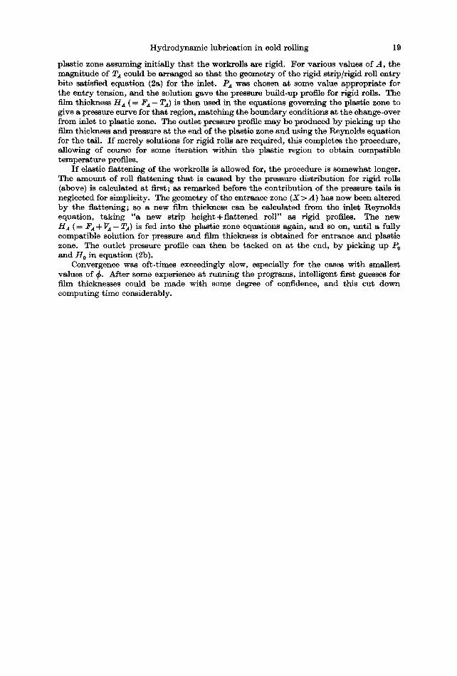
plastic zone assuming initially tha t the workrolls are rigid. For various values of A, the magnitude of T~ could be arranged so that the geometry of the rigid strip/rigid roll entry bite satisfied equation (2a) for the inlet. P~ was chosen at some value appropriate for the entry tension, and the solution gave the pressure build-up profile for rigid rolls. The film thickness Ha ( = ~a - TA) is then used in the equations governing the plastic zone to give a pressure curve for tha t region, matching the boundary conditions at the change-over from inlet to plastic zone. The outlet pressure profile may be produced by picking up the film thickness and pressure at the end of the plastic zone and using the Reynolds equation for the tall. I f merely solutions for rigid rolls are required, this completes the procedure, allowing of course for some iteration within the plastic region to obtain compatible temperature profiles.
I f elastic flattening of the workrolls is allowed for, the procedure is somewhat longer. The amount of roll flattening that is caused by the pressure distribution for rigid rolls (above) is calculated at first; as remarked before the contribution of the pressure tails is neglected for simplicity. The geometry of the entrance zone (X > A) has now been altered by the flattening; so a new film thickness can be calculated from the inlet Reynolds equation, taking "a new strip height+f la t tened roll" as rigid profiles. The new Ha ( = / ~ + VA- T~) is fed into the plastic zone equations again, and so on, unt i l a fully compatible solution for pressure and film thickness is obtained for entrance and plastic zone. The outlet pressure profile can then be tacked on at the end, by picking up P0 and H 0 in equation (2b).
Convergence was oft-times exceedingly slow, especially for the cases with smallest values of 4" After some experience at running the programs, intelligent first guesses for film thicknesses could be made with some degree of confidence, and this cut down computing time considerably.