hydrodinamic design of seaplane floats - cranfield...
TRANSCRIPT

C.P. No. 15 F+ eu2q
A.R C. Technical Report
MINISTRY OF SUPPLY
AERONAUTICAL RESEARCH COUNCIL
CURRENT PAPERS
Hydrodinamic Design of Seaplane Floats
BY
K. M., Tomaszewskl, Inz.Lotn. (Warsaw)
.
, Crown Copyrrght Reserved
LONDON: HIS MAJESTY’S STATIONERY OFFICE \
1950
Price 5s. 6d. net.


Subsequent to the publloatmn of 2his Eport a better )nethod of afterb&Iy des;lgli WAS evolved consxstmg in esseme of fitting the after body to the oalculnted m.lce shape to promile adequate ventilation in the plming condition. Tiiu mei;hcd was applied to the R.A.E. floats described 1~1 shls report and an improved version of the floats prmlucecl. f. su.amary of :;hu o&hod of afterbody design with the results obtained on the K.A.E. floats was presented at the 7th International Congress of Appl-~ed Moohanios and is reported in the Prooeedmgs.'
* Proceedings of the 7th 1ni;ernational Coqqess of Applied Mechanics, 1943.
"Some Aspeots of the Flow Round Planing Seaplane Hull:, or Floats and Improvements in Step and i,fterbcdy Desiyn." - K.i\l. Tomaseewski ati A.'&. Smith.


C.?. No.15 (lo,429
Report NC. Aero 2154
ROULAIRCRAFTESTAT~LISH!~
Hydrcdynarmc Design of Seaplane 3%&s
by
K.M. Tomaszewski, Ins. Lotn. (Warsaw)
A generalised float form together with its attachment to the seaplane is designed on the basis of existing data ati tank tests.
It is shown that a gocil compromise can be achieved between design for water stability, true, spray, seaworthiness on waves, good aercdynamc form, buoyancy ati east of manufacture.
Much strcngcr aftcrbcd~es can be used for floats than for hulls tithout loss of porpaising stabzhty anii a-necessary for gocd stabilitg and trim at the hump speed.
The final form evolved should prove a useful basis for the design of floats for any particular purpose.
LIST OF coNxI\Fps
1 Introduction 2 Design of float gecmetry
2.1 l?irst version fcrebcdy shape 2.11 Forebody length 2.12 BOW height 2.13 I&& he&ght 2.14 Fcrebody deadriso angle 2.15 ?&j
Forc>cdy~~+apc in plan view Ferebcdy bottom shape
_ck 2.>:~F&&7 v~~~lon_.~~~rb~~y.,shapc - 2&e ~titerb&?&%ig~h
5 ,2-f@--, &%%,$$~l?eel~angle to forebody keel. ~T~~$@ %&~~~&?&+Z&ise angle ~~_ '2:2&& Aft-erb-$f leiigth with Ndder
2&q? d&&$@$p&y~ iz2 Q.y vim .-:,2&j. Afterb@~~>cCtcm shape
527. &rst version step form at-d keel height ii>28 'Aftcrbcdy chine height
2.3 Float deck design 2.4 Float attachment
3 Des&&ion of model for testing floats

LIST OF CONTENTS (C&d)
Characteristus of fust version floats
,":: True ard porpoising stability Spray characteristics
hMi.fuzatlcns and their effect on trim, porpoising stability and spray on calm water 5.1 Mcdiflcation "A" 5.2 Modification "B" 5.3 Idcdrficat~on "C" Seaworthiness with modification "C" 6.1 Take-off in waves 6.2 Aft taxymg Mcdifuzations and their effect on buoyancy Oonclusicns Lut of Symbols References
LIST OF 'TABLES
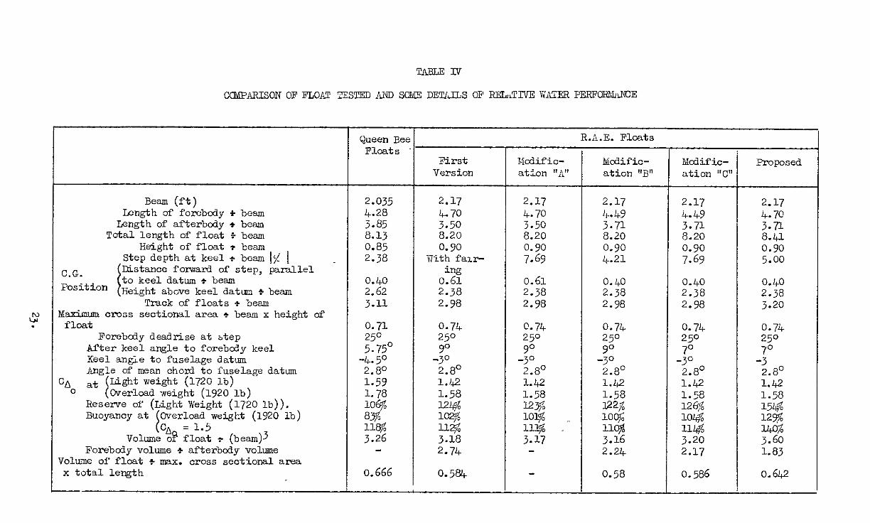
Float dimensions In terms of beam first version) Float dunensicns in terms of beam mcdifiaaticn “C”) List of m&.fioations Ccmpatison of floats tested and sane details of relative water performance
seavm-thinesn m waves Aft taxying performance
LIST OF ILLUSTRA'ITONS
The geometry of the forebcdy expressed non-dimensionally Forebcdy deadrise distribution Determination of the bottcm of the float The forebcily bottcm curve The gecmetry of the afterbody expressed non-dimensionally pfterbcdy deadrise distribution General arrangement of float attachment General arrangement light seaplane on R.A.E. floats R.A.E. float lines - first version and mod. "A." and "B" R.A.E. float lines - mod~ficatwn "C" Porpcising stability during landing and take-off, R.A.E.
floats - first verslcn Pcrpoising stability during take-off, R.A.E. floats - m&.f'ioations "A" and "B"
Porpoising stabilzty during landing and take-off, R.A.E. floats - mcdifioation "C"
Attitudes with the stick central during take-off at overload Stability llmrts during take-off at overload without disturbance
Stability 1imlt.s durug take-off at overload vrith 7' disturbance
Comparison of angles of elevator at stability limits with disturbance
~cmparison of elevator sensitivity at stability limits with disturbance i
2.
10 10 11 11
11
ii 12
:: 13 UC 16 lb
Table
I II
III
Iv v VI
FiJp
1.1 1.2 1.3
::; 1.6 1.7 2
:::
4
5
6 ?A
7B
7C
8A
8B
*.

LIST OF ILLUSEk4TIOI\E (Gontd)
spray characteristws on calm water during landing at lqht load 1720 lb A.V.W. R.A.E. floats - first version
Spray characteristics on calm waix.r during take off at overload 1920 lb R.A.E. floats - rust vcr8Lon
Wave test cooditions (zero wind) Spray charactermt-Lcs in waves, height = 1.25 ft, length = 25 ft, Zero wind conditions. R.A.E. fIca.ts - mdlfication "0
Spray oharacteristxs in waves, height : 2.1 ft, length = 84 ft, Zero wind oonditlons. R.A.E. floats - mcd~float2.on "C"
Proposed lmes of R.A.E. float Variation of rcservc of buoyancy with static beam loading
coefficient Variation of draft wxth att-itude and statlo beam loadwg
coefficient , Variation of distance of buoyancy from F.P. for constant
statrc beam loading coeffrcxnt (CA = 1.5). 0
9
10 11
I.2
13 14
15
16
17
1 Introduction
The purpose of' fhrs report is to examue the geometry of seaplane floats and their position relative to the C.G. for porpolsing stability, spray clearance and seaworthiness.
,A pair of floats and their a%tachment to n small seaplane have beer desi#ed and tested i,l the B.h..S. seaplane towing tank, to illustrate the principles znvolved. The des~n features are however set out '1.3 a non-dimensio~ml form for general use.
Teshs with float-seaplanes have shown1 that deslyn for porpoising stabiiify IS more severe for flying-boats, than float-seaplanes. It 1s necessary ho design for much deeper steps, higher and smaller af'terbcdier: for the foimer. Par this reason the shape of the 'floats was based X/I j;he first place on flying-boat hull design and later cboges we& umde by strengthening the afterbody to improve stability and trim i,? the hump i-eglon. The deslg‘? layout WL?S chosei a.~ requirements and theoretical design.
n compromise between manufaci;uring
'the water characteristxcs of the h~~fl-float-seaplane are determined by six main parameters: (1) stat-it load oil the water (beam of the float and total wiyht of seaplane), (2) geometry of' the float m terms of the beam, (3) posxtion of the step of Lhe float relaTive to the C.G. of sea- plane, (4) van6 settmy relative to the float, (5) aercx3yncmic character- ~scios and (h) track of float ,(d?.staae between the centres of floats). The float design for &ocd po~pouing stability ati seaworthiness is a series of com~romiscs betweeo these parameters,
In khis report the parameters (2) and 3) are uvesti&ated for coostnnt values of the parameters (1) (1,) t5) and (5). The beam of the float was ,chosen for a static be& lgding coefficient Cd = 1.5
0, ati has been kept constant. At this beam loadzng the volume of the float was chosen to grve resenre buoyancy of ll$ on the orrgi~~l form. It w.s mcreased to 140,; for the fIna proposed form.
The pod.tlon of %he float relntlve to the C.G. of the seaplane MC. first fixed for static stabilxt$ and then modlflcd to satrsfg the results: of the tru and stability tests or a powered-dynamic model. For all tests the wiAg setting relative %o the float datum was kept constant2 at 5.8’. A powered-dynsmic mcdel of djhe Auster V ~a6 used, so keeping the aerdynam~c characten stlcs constant'for all the mcdificatioas. The track of the floats was thi: sane as for the Auster V with "Queen Bee" floats but observation of spray co~ldx.tions during the tests show that better results may be obtained rf the track be increased. This will also unprove the lateral stabikty. The increase is however limited because. seaplanes with large tracks are difficult to keep on a straight course when landing on one float. C.A.G.I. recommended that the track of floats be 15 to 2@ of the wing spm3.
Stability an3 seaworthiness tests were made both in calm water and waves.
2 Design of float geometry
In the design of a float ior gocd porpolsing stability and sea- worthiness it is oonvenient to consLder three different coiiitions on tho water; (1) at rest or at low speed (the displnoemcnt region), (2) during transition from displacement to pl&ing flow (the hump region) and (3) planiilg on the forebody (the planing region). These three different

corditmns depend on (a) forebody geometry, (b) geometry of step, (o) pecmetry of afterbody and (cl) location of floats relative to the seaplane. From available ioformacion on existing desl@;ns of floats axl hulls for a given static beam loadin,: coefficient (CL ) the
0
geometry of the required float may be solved non-d~mensionally in terns of the beam and from static stability coosideratl.ons the floats may be located relative to the seaplane.
Floats designed In this manner still require testing in a towing tank in order to obtain the best final form for any given operational requirements.
The lines of the first vers10,q of the float design are given in wg. 3.1 and the dimensions in terms of the beam in Table I. The denvatlon 1s as below.
2.1 __ First version forebcdy shape
The shape of the forebody affects co.ditlons on the water during take-off, landing and taxying. A long forebdiy with a fine bow gives good spray clearance and hgh static trim in the displacement region.
A low forebody deadrise angle 1s better for resistance and lower limit porpoisr,lg stability, and a high deadrise for impact and spray oharxter- 1st1cs. In the planing region a flat bottom (small deadrrse) with constant beam and no keel rise is necessary to obtain the maxxnum normal force with the minimum wetted area.
2.11 Forebcdy length
There are i,l exis~enoe several emprrxal rules giving forebcdy length (8,) in terms of beam (b) for a given statlo beam loading ooofflcient (in cur case C, = 1.5) required to satisfy spray conditions and static stability. 0
Parkinson gxves the formula'"
% 0 eF=b. - J K
where K = constant.
Then for K = 0.0525, K = 0.0675, K = 0.0825,
K = 0.0975,
I very light spray), 8, = 5.35.b satisfactory spray), + = 4.7l.b heavy but acceptable
(exocssive spray),
Locke5 gives the forebcdy length in terms of beam and static beam loading coefficient to provide flotation at rest and to prevent nosing under when taking-off or alighting as
1 eF = 3.5.b.Q 7 .
0
5.

For cao = 1.5, e# = 4.h.
All the exist~.~q rules for the forebody length are very empirical an.3 must be used very carefully.
In the preliminary design of ihe floats the forebdiy leng't'h was chosen as + = 4.7.b.
2.u Bow hei+,ht
If %tk f'orcbcdy le@;h is shor+, a h-L&h bow reduces I;he buoyancy and hydrcdynsmlc lift of the forebdiy at low speeds so increasing the resistance and spray seveiicly.
In rough water a low bow gives rue to very severe spray. If xhe forcbcdy 1s lensthe‘led sufficiently and at the silllie txme the bow 15 raised, the entrance unto the water u less abrupt and the spray characteristics are unproved. A hLg,h bow wxth large forebody length ml&ht be md~e favourable eve,, xn smoosh water. For the large forebody length of + = &.7.b, the height of ?he boli was chosen as hb = 0.75.b, for godi spray conditions on calm and rough water.
2.13 Keel height
In the planlag re&io,l the best resul';s are obtalned w.th no keel r-lse. For bhls reason the keel 11~1~ 1s made straight for a dutance 8, = 1.7.b forward of the step. This asbuues ICat this is the maximum we,.ed length of the keel durin& planins. Frcm ec = 1.7.b to the bow -the keel lil?e rxses as an ellqxe w.?h semL-major ax~s (.$ - 8,) = J.b ati semi liu.nor ~X-LS b = 0.75.b. All .elliptwal shape with a large bw deadrlse a,~,:le gves reasonable air drag and 8003 buoyancy at rest. The keel lone desi.@ed in this way is drawn in FIN. 1.1. He18hts arc ~I.VC~ in terms of the beam.
1.11, Forebody deadrise angle
It 3.5 necessary to be very careful xn ohoosins the forcbsby deadnse because \he vdr~ous rcqurcments qonf'lxt with one another.
To g-l.ve effi.c-Lent lifti@ clharacterlstxs ii1 planlnfi, a flat bobi;cxn LS the hest form for the forebcdy (deadrrsc az~glc zero) but such desi.&n @.ves very large Lnpact forces durug landing and bad spray ctwraoter~stux3. The ~~~ilcrease of deadnse angle reduces these forces x?d spray severity but ra.~ses the lower limsi; of stabilxty and causes deterioration in planing charactel~s~:Lcs. Increase in the angle of deadrise from the step to the bow g:lves a sli&ht reduotLon of the res-Lstance before the hump speed and unproves the cleanness of running 2.n waves. At the hump speed the part of the float afr'ected by thu chawe of deadnse angle is completely clear of the water in calm conditions. It appears, therefore, that from the design point'of view the forebody deadrrse angle may be co,wdered ln two parts. -The forvmrd half of the float forebody, desIgned from the polnt of v*ew of the low-speed rough water charaoteri.stics, =fld the after half, frojn the point of vxew of the hump rexstance, lower limit porpolsing stabilLty, yocd planing chnracterlstxzs impa& and spray conditlofls. In dcsLgni.n& the forward part of the forebody to reduce spray over the wlndscreeq and inso the propellers, oare should be t&kcil to select a form whch ~i,ll &?ve easy entry into waves encountered head-on. By
6.

raising the bcvi the force of' the impact with the oncming waves 1s reduced. It appears that satisfactory bowspray characteristics may be obtained wthout cwnpromising the planlnj charao-,;en.stics and any change which softens the napact between float and graves teads to reduce the spray. American tests show6 that increns~ng the angle of deadrise at the bow has little or no effect on the minunlun air dray or angle of minimum drag. 'To obtain a low lower-limit of porpoising stability, good planxng characterzstics and reasonable forces due to unpact when landzng, the dcadrisc angle at the main step was chosen as em = 25O and kept constant for -Cc = 1.7.b. !J!o obtain the best spray formation especially on waves the desdnse angle zncreased smoothly from JSc = 1.7.b to the bow. The change of deadrise angle with the fore- body length was chosen from tho spray analysis 7 and 1s represented in fig. 1.2. The mcrease of deadrise angle at the buw was considerably greater than had normally been used in the past.
2.15 Forebody shape in plan view
For planing the breadth of the part of a float wetted should be constant. 'i'he breadth of the float is therefore kept constant (b, = b), from the step forward to 6, = 1.7.b. Frcm e, = 1.7.b to the bw the plan view is part of a "Standard" stresmlrne form 8 with a maximum diameter correspotiing to the beam at de, = 1.7.b (49 of the total length of a streamline). Such a form should give goad planing characteristics and low air drag. Fig. 1.1 gives the local beam of the forebcdy ii7 terms of beam at mszn step.
2.15 Forebody chrne height
The forebody ch-Lne line may be obtained for each transverse plane of the float as an intersection of the local deadrise wxth the chine half breadth, the latter bean@, obtained from the forebcdy plan view of the float. Fig,. 13 show the method of obtaining the chine lme and Fig. 1.1 the height of the chine in terms of tihe beam along the forebody length.
2.17 Forebody bottom shape
Concave curvature at the forebody bottom improves the spray conditions and reduces mpact forces but makes for some ccmplrcatlon in manufac-curxnc the floats. Constant curvature of the bottom reduces this complication a little. For this reason the curvature of the forebody bottom was chosen as a coo&ant symmetrical parabola between keel aed chine for all transverse sections of the forebody. Frg. 1.4 represents the shape and method of drawi-ig this parabola and Fig. 1.3 gives the locatxon of thus curvature relative to keel or chine lines of the float.
2.2 First version afterbody shape
The design of the afterbdiy is very closely connected with the design of the main step. Some information LS given in references 5 and 10 on the effect of dimensions and proportion of the afterbody on the water charactermtws of the hull or floats.
2.21 Afterbody length
At low and medium speeds (hump speed) the afterbody serves to provide aft buoyancy and prevent the attitude from becoming too high
7.

at the hump speed. At hlyh speeds (\+heo plaiung) ';he lenfith of the af-herbody should be as short as possible. A long afterbody leads to porpoisu7g on I;he upper 13mz.t of instabiliby. Near i;he hump speed a strong afterbody lowers the lower limit of lnstab'*lity. The requrre- merits for the length of the afterbcdy are therefore conflicting - long at low speeds and short at hi&h speeds. Sni.:;h ai7d rih&11 recommended that the length of afterbody for boat seaplane be 2.5 to 3.0 of beam with a pointed rear step,
Locke 4 gives a i'o~~~la for \he averase Length of she afterbody,
1
for
4, = 2.5 . CA 3 . b, 0
% = 1.5, .Sa = 2.9 . b.
The R.A.E. tests wzth float-seaplanes show'. that floats with afterbodics up GO 3.8 tunes the-bcsm and pointed rear steps have large stable ranges at both hump an3 planing speeds. For this reason the length of nfterboily for the f-irst tests was chosen as 4, = 3.2.b.
2.22 Afterbody keel an&e to f'orebdy keel
The angle of the afterbody keel GO the forebody keel at the step has a large effect 0‘1 trim, water rcsutance, porpox.srng stability and sklppina of the seaplax. At lcw speeds, including the hump speed, morease in zhe afterkeel angle reduces the buoyancy and the hydro- dynamic llfc of the afterbcdy. 'To compensate for :;hls rvduction io lift the floats tend to assulllc a hlghcr tr%ll. lit wry low speeds ihrs increase 1.n trlrn is s\mall and the ohanpe i,? ~cslstance is neyllgible. The maximum effect 1s at -the hump speed at which increase in afterkecl angle causes a large =,yorcase ii7 trim and acccmpanying large uxxease xn free-to-trm reslstanc~. At planing speeds however, rt lowers the resxtance and improiros tne s+ab~l~ty. A low after- keel angle e;vcs cleaaest runnuq but ;ives a lower upper l-unit of stability just above the hump speed. According to Amcrxan test&+ the low afterkeel angle prcvc~ts slcLppin2 especially in rough tiater. For the flrst tests the afterkoel angle was chosen as 9O azd the keel hne made straight. If the results of tests with such a hikh after- keel angle shrx that free-to-trim an$es at the hump speed arc large the aftcrkcel ZGX&C could be reduced to 7' as proposed by %mlth and Whxtell, for the minimum afterkeel aable (for flying boats) &'ving satufaotory porpoisrng stabil-*ly at planing speeds.
2.23 Afterbody deadrise ankle
A larger deadr?se angle on the afterbtiy than on the forcbody at the step posllion improves the ventilation-of the after-body bottom. This causes improvement i.~ the ventilation of the f'orward half of the afterbody, unprovement ir7 the upper limit of porpouiiig stability in the planing region and nllevxatos skippipg. The aft half of the afterbody co,ltrols the upper liml t of porpoisuq, stability near the
A more pointed fear step generally gives an improvement ~~:t:t%ty% Increasing the an&e of deadrIse aft on the afterbody decreases the lift of the afterbcdy and therefore ucreases the trim and relstance at the hump. Most of this ixreased rcsutance is due to the hxgher trim. Full scale aft taxying tests with floats hamng decreasing aft deadrrse in the afterbody shat$ dangerous il~vlng te,ldency even at very low taxying speeds. TiIJ s teXJenoy 50 d-ivc 1s ma3.nly
ir.

because of the suotun on the after part of the afterbody bottom which occurs when the chwe is immersed. If the deadrise angle IS increased towards Ghe rear step dlviny ca;r be elimi,lated.
The selected distribution of deadnse angle 1.s given in Fig. 1.6.
2.24 Kfterbdy len&h with rudder
To improve control 0~1 the water at 10~ speeds the afterbcdy length was increased 60 3.5.b to accomncdate a water rudder.
2.25 Afterbcdy s'hape in plan vl.ew -
The @an VIXW of the afterbody LS the after part of' the "3treaniLLle" form' used oa the front of the forebcdy. Aiiximum diameter correspotis to that at the step po&itlon and the tra~l~ni; edge of the streaml-Lne occurs at 3.L.b from the step. Decause of the rudder the end of the stremllne form was mcdifled as shown Pi&,. 1.5.
2.26 afterbdly bottom shape -
For the first scr3.e~ of' tests the sides of the af;;erbcdy bottom were mde flat, FL@,. 1.3 &?d Pig. 3.1.
2.27 Rrst version step form and keel height
At speeds below ati at the hump a small depth of step u desrrable for low resutanoe. At hqh speeds the water resistaxe decreases as the depth of step is increased due to a sreater clearance of the after- body from the water (better ventilatuzn of the afterbody bottom). For constant value of the afterkeel angle the water resistance decreases a~ the depth of si;ep IS -*noreased up to a certarn depth beyond which no further reduction I.S obtaued. This value of the step depth depends on the afterbcdy keel lue. For shallow steps when the attitude of the float is such that the afterbcily keel IS nearly horizontal, the flow from the step suddenly tends to cover the ensue afterbcdy planing surface and the resutancc and draft are suddenly increased. Thx is acccmpan~ed by longitudinal rnstabilia:y. Increasing :Lhe dept of step remcves the tendency toward rnstability. .Amerxan tests show b that a 75s increase xn depth of step (from 2.3, to 4.4; of the beam) caused a very small ucrease UI aercdynamrc drag and very marked improvemect in stabi.l-Lty.
For the first tests the depth of step was chosen cls 7.7 percent of beam at main step. The step was faued i.c eleva&x to a dxstanoe approximately four times the step depth.
The height of the keel line is gi.ven in FL&. 1.5. To reduce forces cn the rudder when landxq, cn two steps the afterkeel angle of the rudder 1s raised to loo.
2.28 s
The afterbcdy chl,lc heibht may be obtained by the same method ab for the forebcdy chine height. Fig. 1.5 shcws the hezght of the chine line In terms of beam along the afterbcdy length ati FI&. 1.3 the method of obtaining thus height.
2.3 Float deck design
The shape of ihe deck was desl.gned for lag air dray. 'The top liae of the deck from the bw to 6, = 0.P.b is an ellrpse and then a
9. .
straight line parallel to the datum line of the float and ending as a part of a "Standard" streamline form7. The E&US of the float body v!as taken as half the breadth of the float. The deck line and the height of the radius ocntre above datum is given in Frg. 1.5 in terms of the beam at main stop.
2.4 Float' attachncnt '
The float attachment was designed m a trouser leg form for minimum air drag and maximum strength. This form.also has minimum intorfcrcncc with tho spray formed by the floats. The leg can be varied in transvcrsc angle as requ-Lrcd relative to the float. The upper end of tho streamline leg can be attached to any rcnsonablc part on the fuselage or wing.
Data ard illustrations are gxven in Pig. 1.7 in terms of the beam at main step.
5 Eosoription of Mcdcl for Testing Floats _
To oxamino true, stability and spray formation of these floats on calm iiratcr and waves the floats' wore fixed to a 1/5th scale powered- dynaniic mcdcl of'thc Austcr V. The full scale besm of the float was chosen for a normal take-off weight of the sircraft (1820 lb),
whcrc " a = 1820 0
- = 910 lb = static load on the water 2
‘CA = 1.5 = static beam-loading coefficient 0
W = 62.5 lb/ft3 = density of fresh w,\ter
b = 26 inches
The general arrangement of seaplane is given in Fig. 2, and the float dimensions in Fig. 3.1.
4 Chmxctonstux of First Version Floats
4.1 Trim and porpoising stability
The zosults arc given in Fig. 4 for take-off at overload (CA, = 1.58) and Laxd.ing at light load (CA, = 1.42). 'The mcdcl has a poor lowor limit of stability, being unstable mthout disturbance at all speeds above 20 knots when left free to trvn with elevator neutral. This instability bcccmcs less scvero as the take-off speed is reached.
The attitude, when the model is left free-to-trim with elevator neutral, lncrcnscs sharply \,ath speed as it apprmohes the hump (15.9 knots) and then decreases rapidly, giving a large variation of trim with speed.
It is not possible to increase the attitude suffsciontly to reach nn upper limit of stability despLtc ample ulovator power.
10.
SPCCd.
With slipstream, the elevator is very cf'fcctiwt even at the hump
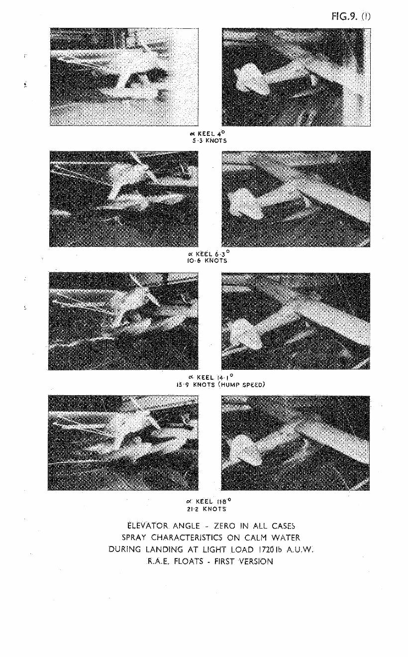
4.2 Spmy char,?ctcrrst-Lcs
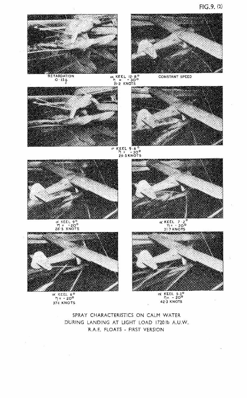
Spray chsmcter~stxs arc shown in Fig. 9 for landln load (CA, = 1.42) and In Frg. 10 for take-off at overload fc:; FE8);
The propcllcr and wit&,creen arc clear of spray at all take-off and landing speeds.
At low speeds (up to 10.6 knots) the floats are very clean and no part of the scnplanc is affected by the spray. In the hump speed range the spray, due to lnterfercnoc between the two floats, wets the undersurface of the central and nft parts of the fuselage. At planing speeds the floats are agc&.n very clean and no part of the seaplane is affected by the spray.
5 Modifications and their effect on trim, porpoisinp: stability and spray on calmwater i
To improve the lower limit of stab.bllity an3 decrease the attitude at the hump speed three modifications were made. First the faring was rcmovcd frdm the step - Mod. "A". Second the step was moved forward 21s of the beam at main step (step depth at keel reduced to 4.21% of beam at main step) - Model "JY'. Third the afterbody was strengthcned - Mcit "C" . . Table II gives the dimensions of the float in terns of the beam at the m&n step for modification "C" and Fig. 3.2 represents the float lines.
The effect of the mcdxfrcntlons are summarised in Table 111 and illustrated m Figs. 4 to 6. A ccmpar~son of the drffcront floats is made in Table IV. Fig. 7 gives a ccmpnrrson of attitudes with the stick central and stability limits with and without dlsturbance during take-off at overload. Fxg. 8 capares the dlffcrcnt stick positions which make the flat unstable and also the rate of change of attitude with elevator angle on the stability ljmits.
5.1 Modification "A"
The results of porpoisin stability tests are given in Fig. 5A for take-off case at overload fC& = 1.583. Ccmpnrison of the first version xi.th mcdifiontion "A" shc& that removing the fG.ring frca the step gives:
(1) A reduction of hump attitude of about p ( TJ = O'),
(2) n lowering of the stability limit of about 2' in the speed range just above tho hump,
(3) an inprovement of elevator sensitivity on the stability limit,
(4) o more central stick posztion on the stability limit below 40 knots,
(5) n farther back stick position on the stability ltiait abwe 40 knots,
(6) a slight improvcmont in spray charaotenstics at tht: hump speed probably due to a lower attitude,
(7) a reduction of buoyancy 0.s relative to the first version.
11.

5.2 Mcddlcation "B"
The results of porpoising stability tests arc given ln Frg. 6B 'for take-off at overload (CA with "B" shows that novinig t R
= 1.58). Capnrison of modification "A" e step forward gives:
(1) (2)
(3)
(4)
(5)
5.3
no change of attitude at hwp speed,
a lowerrng of the stabrlity ltilrt of about l&O ai speeds just above the hump,
a worse elevator scxltxvity on the stability linit,
a more cenixxl stick positaon on the stabb-Llity limit,
a reduction of buoyancy O.Fb relative to the fxrst version.
Mcdifscation "C"
The results of porpoislng stability tests arc given ln Pig. 6 for landing and take-off at ovorlcad (CA, = 1.58). Complpnri&?n of mcdificnt~ons "B" and "C" shoT,,s that strcngthenhng'~he afterbDdy gives:
(1)
(2)
(3,
(4)
(5)
(6)
a reduction of hump attitude (v = 0') of about 1;' (about 2' when compnrcd with first verslon of floats),
a lowering of the stability limit of about ho (about 3.7’ when compared uLth first version of floats) just above the hump speed,
a wxdcr stoblc range of speeds and attitudes without disturbances,
n more constant elevator sensitivity on the stability limit,
nr;iight tiprovanent in spray ohnmcteristlcs in the htzlp speed range,
I> a17 in&ease of buoyancy O.$ relative to the first version.
.s It is expected that oven m rough water conditions (with large d&J- 'I turbnnces) the floats will be stable during take-off at attitudes~above 6' due to the fa&t that the unstable range with disturbances is very I narrow nnd during acceletitcd motion the seaplane @sees through the unstable region just above the hump so quickly that &stabllity has no tme to bulld up.
6 Se,?worthLness with mcdifioation "C"
6.1 Take-oiY Ln waves
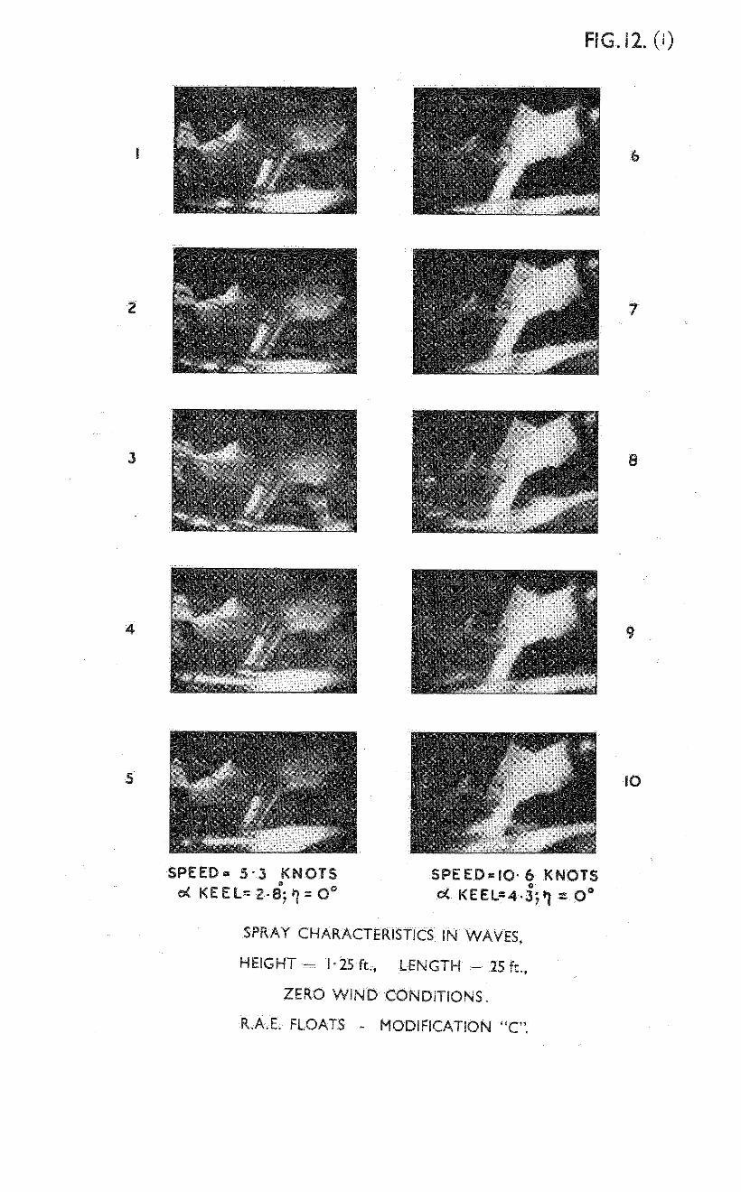
Tests have been made v&th four different systems of waves ,l.5 and in zero wind conditions. Fig. 11 shows the wave test oonditions~ l&i.'12 the spray charrrctcrrstlcs obttincd for waves 1.25 ft height and 25 ft long, Fig. 13 the sGny charactcr*stws for waves 2.1 ft haght and 84 ft,long. Tab16 V stzmansos'thc results of the tests An wvos and calm water.
These tests show that small waves up to 0.8 ft (wave height: float be3r?l = 0.37) improve the spray characteristics in hump region by reducing the &terf'eronce bctwecn the two floats. With larger waves up to 2.1 ft (wave height: float be,un = 0.99) the floats are very clean at low speeds but m the hump speed rango the spray due to the blister intcrforence between the two floats hzts the undersurface of the fusolagc
l-2. .
slightly. This occurs when the seaplane runs at very small and very large attitudes due to the effect of tho WIVES. floats are very clean.
At medium attitudes the At speeds just before take-off the model starts
to bounce at higher attitudes.
6.2 Aft taxying :
Full scale experience shows that float seaplanes can be lost because of a very dangerous tendency to dive when taxying in an aft direction. Aft taxying tests were mcde in R.I~.E. Seaplane Tank with R.A.E. floats - modification "C". The model was free to pitch and rise abouts its C.G. at overload. Tests were mode at spctds up to 15.9 knots (full scale) without disturbances and with small and large disturbances. The results of tests arc tabulated in Table VI. Those tests show that in aft taxying on calm water (no disturbances) there is no tendency to dive. Up to a speed of about 8 knots the seaplane runs similarly to normal forward taxying and no part of the aircraft is affected by the spray. At speeds higher than 10.6 knots the soa- plane runs bow down and at a spcod of 13.2 knots and above it runs with the rear step clear of the water but spray hits the propeller. When small disturbances were applied the seaplane behaved in the same way as without disturbances up to a speed of 8 knots. At a speed of 10.6 knots and above there is a slight tendonoy to dive (bow up) which starts to be dangerous at a speed of 15.9 knots. Large dis- turbances causing complete submerging of the aft part of the float do not affect stability up to a speed of 6.6 knots, but at a speed of 8 knots there is a slight tendency to dive (bow up) and at a speed of 13.2 knots and ‘above the seaplane dives (bow up).
These tests show that up to a speed of 6.6 knots the aft taxying condition is very safe even when large disturbances are applied, It is expected that in practice the aft taxying performance will be much better because the model was pulled through its C.G. position.
7 Mcdificataons and their effect on buoyancy
M.A.E.E. tests of the Auster with "Queen Bee" floats showed that the floats were just satisfactory for buoyancy and stability in calm conditions but at overload and in disturbed sea conditions the buoyancy was on the low side.
Table IV gives a ccmpnrison,of the buoyances of the "Queen Bee" ard the varicus R.A.E. floats. Fig. 15 shows the variation of reserve of buoyancy with static beam locding oocfficient for the first version, modification Y? :t "Queen Bee " and proposed floats. It can be seen that at overload the Queen Bee" floats have only 8% reseme buoyancy, whereas that of the R.A.E. floats tested is lo@,< to lOi& and that of the proposed floats 129";;. For the sane static beam loading coefficient the total buoyancy of the R.A.E. floats tested is 1 to 3 percent smaller than that of the "Queen Bee" floats. The total buoyancy of the proposed floats is 10 percent greater than that of the "Queen Bee" floats.
Fig. 16 gives the variation of draft with attitude and static beam loading coefficient for the first version and the proposed R.A.E. floats. This figure shows that for the same values of CA, and attitude the draft is smaller for the proposed floats thsn for the first version floats; The difference in draft betireen these two floats is greater at higher attitudes and higher static beam loading coefficients. For Cao = 1.5 the difference in draft would be as follows:
13. .

,,ttitude degrees
-3O
6’
Percentage Reduction --
4;:
s,l
Fig. 17 gives the variatmn of the distaaoe of the lxne of buoyancy frol~ the F.P. for constant static beam loading coefficient (ca, = 1.5) f or the first version and proposed R..,.E. floats. Comparison of the two floats shows that for the sam position of C.G. the statz.c flontmg angle will be smiler for the proposed floats. For coostant height of C.G. above the float datum the dirference in floating angle increases ahon the C.G. is nearer the step.
8 Conclusxons
The interesting features of the float dcslgn considered m this report arc (1) the grcatzr frecdm of dosign pormissiblc compared with hull design which results from the possible USC of strong afterbodies and shallow steps, (2) the good stabilzty, trin and sea- worthlncss achievable at a high beam loading.
No uppor 1iM.t of porpoasing stability is present, and the floats arc very well behaved ~.n waves up to a h+,ht equal to th; beem. In addition the floats can bc towed in an aft direction wlthout diving, oven when subjcctcd to a tail down disturbance.
The lower limit of stability is very high at the hump spced on the floats tcstcd with weak aftcrbodles, so that poor stability resulted for the first version which was based on boat seaplane hull design. Thus stability was oonsrderably L~provcd by USC of a strong aftcrbcdy without the introduction of an upper 1tixi.t nt high speeds, n solution not possible with boat seaplane hulls.
The rcqaircments for good spray conditions are shax to be a fxne entry oombined with J. high bow, ample reserve buoyancy forward and an overall reserve buoyancy of at least 100 percent. To avoid interference between the floats the trcck (dlstnnce between them) should be at least 3.2 rims the beLam at the m,ain step.
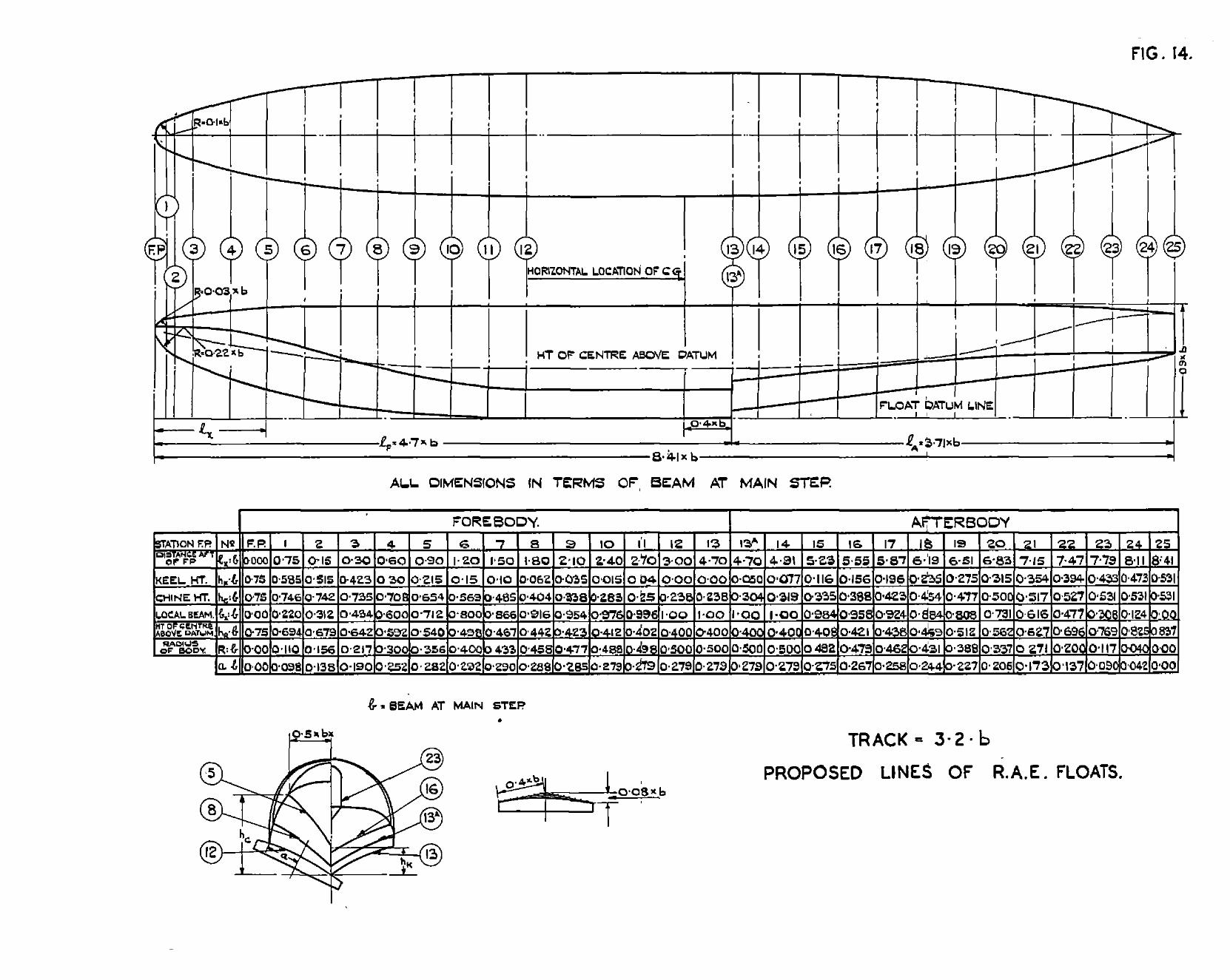
It 1s consxdered that further improvement of the float form "C" my be obtained by lowcnng the afterbcdy so that the step depth is reduced from 7.7 to 5 pcroent of the bea, as shown in F'lg. 14. Ths is based on the following reasons:
(1) nt speeds below and at the hulp speed a smaller depth of step reduces the rcsistancc.
(2) In the help sped mnge the float vath stronger Lafterbcdy has a lower free-to-tnn attitude and lower limit of stability.
(3) The tests of the i,uster V on the . “Oueen Bee" floats with a depth of step of 2.38 percent of the benm show that floats with such small depth have quite c reasonable lower l&it of stability and no upper limit despite oz.~plo elevator power.
14.

(4) 1, stronger afterbody and forebcdy will reduce the tendency to nose up and down in waves an3 by causing the floats to run at medim. attitudes at the hump speed will reduce the spray.
(5) Floats with a stronger afterbody ml1 not reach suoh high attitudes when planing on waves and will have loss tetxlcncy to bounce.
In conclusion it is comidcred ttmt the dynaic design features discussed in this report, together with the static &sign features described in refercnco 2, will enable a designer to achieve a good float design for my desired opcmtional condition. imy suoh float fon;l should be tank tested if possible.
15.

LIST OF SYMBOLS
= nttitudc rclutlvc to the forebody keel at the stop
= elevator angle
= afterkeel angle
= heel to heel angle
= overall deadrise x~glc
= deadrise angle at keel
q deadrise an,@ at chine
= mean deadrisc angle
= beam nt main step
= local bea
= distance aft frm F.P. along datum line of ttx float
= mxi~.~m wetted length of the keel of the-forebcdy during planmg (assumd.)
= the forebody length
= the afterbcdy length
= the afterbody length with rudder
= keel height above float datum
= chine height abovu float datum
= bow height above float datum
= height of mdius centre above float datum
= radus of the float body
= dock~hc&,ht above float datm
= distan'cem'oof C.G. frm s&p along float datum
~= heigh>,Gf'C.G. ?bove float datum .=_,-i-.
s~~~~~o~~~~~~~~~-~~-~,een the centres of floats)
= $ve.height (c&st to trough) 2-e: s ~Ci~e~~~~~~R
= drstmce of buoyancy frcm F.P.
16.

Speed:
v
'h
vt
'b
vtax
Density:
w
Forces:
V'o
wn
wL
A0
._. .a
= forw-rd speed of ~aumraft
= hmp speed
= take-off speed
= larding speed
= taxying speed
= 62.5 lb/ft3 density of fresh water
= overload weight
= normal weight
= light weight
= statlo load on the water
Acceleration:
g = 32.19 ft/sec? acceleration due to gravity
Coefficients:
% =g. = velocity coefficient (Fro&e Number)
CA 0
= static beam loading coefficient
aa av
General :
C. G.
F.P.
= elevator sensitivity
= centre of gravity
= forward position of float on float datum.
17.

No. -
1
Author RtZe, etc.
S. Raymond K. Tomaszewski
2 K. Tanaseewski
3 C.A.G.I.
4 J.B. Parkinson
5 F.W.S. Locke
6 J.B. Parkinson R.E. Olson E.C. Draley A.A. Luoma
7
a
10
11
14
15
16
F.W.S. Locke n.L. Bott
E.P. Warner
N.S. Lad C.J. Lina
LG. Smith H.G. White
F.W.S. Locke
H.M. Garner
C.H.E. Warren W.D. Tye
Tank tests on the porpoising stability chara&er-Lstlos of a slnyle engine float seaplane (Auster V). R.A.E. Report No. Rero.2088 November, 1945. A.R.C.7335 (unpublished)
Detormlnatlon of the statzc stability of seaplanes. R.A.E. Report No. hero 2137 June, 1.946. B.R.C. Current Fnper No. U+.
Manual of Gcro-design. Tcm II Hydrcdynsxic of Seaplane. C.6.G.I. Moskwa 1738.
Design Criterions for the Dimensions of the forebcdy of a long range flxny boat. N.b.C.& ARR. 3K00, R.D.T. d 545 NW. 1943 t
1~ correlation of the dimensions, proportions an3. loading of existing seaplane floats anJ. flying-boat hulls. N.A.C.A. ARR. m/c/404.
ircrodynamio and hydrcdynsnnc tests of models of flying-boat hulls derived from a stresm- line body. 1i.i~. C.A. model 84 series. N .A.C.A. ,ARR. No. 3115, RDT/l/c/ No. 500 September, 1943
i. methcd for making quantitative studies of the main spray oharaoteristics of flymg- boat hull models N.L.C.,.. ;IRR. No. 3K11, R.D.T./c/554.
Airplane design. Performance Mc.Graw-Hxll Book Company, New York ard London, 1936
Tests of a dynamu model in N.L.C.,I. Tank No. 1 to determine the effect of length of afterbcdy, angle of sfterbcdy keel, gross Lo&, and a pointed step on landing ard planing stability. N.ii.C.1,. Z?R. R.D.T./C/398 March, 1943
A rev-xw of the Porpoising Instab.bllity of Seaplanes. M.,:.E.E. Report No. H./RES/l73 February, 1744. . ..R.C. 77W (to be published)
Analysis of the skipping oharaoteristics of scane full sue flying boats, N .A.c.~~. L.R.D. Report NO. M-31 November, .1744
Reoent full scale Mcdel Research on Sea- planes. Lecture of the Lilicntdl-Gesellsohaftt. fir Luftfahrtforschung. 14 October, X938.
Calibration of the wave-maker in the R..,.E. towLng tank. R.,,.E. TeohniosJ. Note No. ;.ero. 1764 March, 1946 ,'.. R.C. 9770 (unpublished)
Wt.2078.CP.15.83. Printed m Gmat Entam 18.


FOKE3OlX
(I?,:b) * 100: / 75
(l+:b) - l@O~i 0
/ I

T:,BLE I (Contd)
FLOAT DIMENSIONS IN TERiviS OF BEAM (First Version)
Station UC 15 16
($@I * 10%
%l"
&:b) - 10%
(h,:b) - lo@
(b,:b) * lo@
(HR:b) - lO'$
@:b) * 10%
(a:b) - lO@
470 502 534
26O 2fP ~6.75~
7.7 12.7 17.7
32.1 36.7 41.7
230 98.4 95.8
40.0 40.2 42.1
50.0 49.2 47.9
-
-
-
-
b = beam at main step h =lccalbeam pX = distance aft from F.P. along datum line hk = keel height above datum line h,, = chine height above datum line hR = height of centre above datm line R = radius of body a = distance frcm oentre of planing bottcm curve
- 17
566 c
28O
22.7
47.1
92.3
43.8
46.2
18 19 20 21 22
598 630 662 694 726
30° 32' 34O 36' 37.25'
27.7 32.7 37.7 42.7 47.7
52.5 56.7 60.4 62.3 62.9
86.1 77.7 67.3 54.2 40.0
46.9 51.2 56.2 62.7 69.6
43.1 38.8 33.7 27.1 20.0
Straight Lime I I
-2j 25
820
38'
65.8
65.8
0
83.7
0

TABLE II
FLOiY!! DIHENSIOIKi IN TR%Xs OF BEAM (Mcdification "C")
-
2
s 51.5 74-2 31.2 67.9 15.6 13.8
3
30 0
2.3 73.5 43.4 64.2 21.7 19.0
mow
13
449 25O 0 23.8 100 40.0 50.0 27.9
FIX -
.
4
60 53.5C 30 70.8 60 59.2 30.0 25.2
7
1550 Go 10 48.5 86.6 46.7 43.3 29.0
S$ation F.P. 1 I I
7.5 550 58.5 74.6 22.0 69.4 11.0 9.8
5%
:: 0 75 0 0
21.5 15 65.4 56.9 71.2 80.0 54.0 49.8 35.6 40.0 28.2 29.2
E .
16 17
534 566 260 26O 18.3 22.3 w.5 45.0 95-8 92.4 42.1 43.8 47.9 46.2 26.7 25.8
- 1 L
-
i - I I - 3 1 -
13A 14 18 19 20 21 22 23 24 25
630 662 694 726 758 790 020 26.25O 270 280 29>5O 33.5O 45O - 30.2 34.2 38.1 !,2.1 46.0 50.0 55.8 50.4 52.7 54.4 55.4 55.8 55.8 55.8 80.8 73.1 61.6 47.7 30.8 2.4 0 51.2 56.2 62.7 69.6 76.9 82.5 83.6 38.8 33.7 27.1 20.0 11.7 4.00 0 22.7 20.6 17.3 13.7 9.00 4.20 0
Station
$2 7.7 32.1 100 40.0 50.0 27.9
F 0 10.4 34.6 100 40.0 50.0 27.9
502 260 14.3 36.2 98.4 40.8 49.2 27.5
598 Z6.5' 26.2 48.1 88.4 46.9 43.1 24.4

LIST OF MODIFICWIONS
Modification Nature of MoTifXcation Effect of Ikdification
Step f&ring removed (Step depth at keel I beam = 7.69;)
(1) Reduction of hunp attitude (q=O") 3bout a. (2) Just above the hump speed the lower stability limit is lowered ~$out 2O ati elevator sensitivity on stability limit iiiproved . (3) Below 40 knots for instability position of stick more centml, above this speed more aft.
(1) step moved forward 2l$ of beam
(1) Hump attitude the same as mcdification
(2) step depth at keel reduced "A" (q=oO)
(step depth at keel+ beam = 4.215) (2) Just above the h&p speed the stability limit is lowered 19 IdatiVe to modif. "A" but elevator se,x-itivity on stability limit worse than modific. "A". (3) On stability limit position of stxk more central than modtiioation "A".
"C" t 1) Step depth as modification "A" 2)
(1) Reduction of hump attitude (q=O") about Position of step as modification l&O relative to mcdir
"7J" (3) Alter keel a@e to forebcdy keel reduced from V" to 7'. (4) Afterbody bottom curve as forebody curve
(2) Just above the hAp?$ed the stability limit is lowered $" relative to mcdific. "B" (3.70 relative to first version)
2 4&e, vn er range of stable speeds without
b L . (4) More constant elevator sensitivity on stability lixt.
CCb!PARISON OF FLOKL' TESl'ED UiD SONE DELLiLS OF RELd'IVE WXIER PERFORhQlNCE
Queen Bee R.d.E. Floats Floats
First Xcdific- Mdific- Mdif ic- PTopfJsed Version at&n "A" ation '%'I ation "C"
Beam (ft) 2.035 2.17 2.17 2.17 2.17 2.17 Length of forcbcdyibeem 4.28 h-70 4.70 4.49 4.49 4.70
Length of afterbody + beam 3.85 3.50 3.50 3.73. 3.TI 3.71 Total length of float f beam 8.13 8.20 8.20 8.20 8.20 8.41
Height of float + beam Step depth at keel + beam 1% 1
0.85 0.90 0.90 0.90 0.90 0.90 2.38 17ith far-
1
7.69 4.21 7.69 5.00 C.G. nistanoe forward of step, padlel Position to keel datum ;L beam 0.4C 0% 0.61 0.40 0.40 0.40
Height above keel datun t beam 2.62 2.38 2.38 2.38 2.38 2.38 Tlack of floats + beam 3.11 2.98 2.98 2.98 2.98 3.20
Gximum cross sectiorul area z beaz x height of float 0.71 O-74 0.74 0.74 0.74 0.74
Forebdy deadrise at step 0
T75o 25O 25O 25O 25-3 25O
After keel angle to forebdy keel go V0 9O 7O 7O Keel angle to fuselage datum -4.50 -30 -30
2.8' -30
Angle of man chord to fuselage datum 2.8O 2.8O -30
2.8' 2.8' -3 2.8'
?A at (Light weight (1720 lb) 1.59 1.42 1.42 0 (Overload weight (1920 lb)
1.42 1.42 1.42 1.78
Reserve of (Light Weight (1720 lb)). 1.58 1.58 1.58 1.58 1.58
Buoyancy at I Overload weight (1920 lb)
10% 83%
l-q% 12%
11% 102jj 101%
122% 12611, 15% 10% 10%
Voluinec% ;1',;: T (beam)3 3.26 11% 111% .-
12% 113 llLi$ w
3.18 3.17 3.16 3.20 3.60 Forebcdy volume + afterbody VO~LUIMZ 2.74 2.24 2.17 1.83
Voltxne of float * max. cross sectional area x total length 0.666 0.584 0.58 0.586 0.642
-

'DBLE IV (Contd.) C~hFiISON OF FLO,.T TESTED AND SCKE DE!kILS CF K3u!i?IVE W;:TER PERFORvfilNCE
R .l,.E. Floats Queen Bee
FJoat s First
, Version
I lhkc - off 2.t~ overload -Flaps 20'
Maximum attitude (relative to kc&datum) cn stability limit with 7' distur. Correspo~w (Sped (knots)
(Incidence of mean chord Maximum attitude (relative tc keel datum) on stability
limit without drstur. Ccrresponding (Speed (fiots) (Incidence of mean chord.
Maximum attitude (Rclatlve to keel datum) for elwator position q= 0" , . Comespoding ~SPQ~ G-tsl
(Incidence of mean chord)
bTa.ximum attitude (relative to keel datum) on stability limit with 7O dlstur. Correspording(Speed (knots)
(Incidence of.mean chord Maximun~ attitude (relative to keel datum)for elevator
posrtion q= O" &rresponding(Sped (kncts)
(Incidence of man chord
7.70 26.25 15O
7.7O 26.25 15O
I 9.250 12.4O l.l.8' 11.8'
12.7' 20.5 18.5'
10.80 21.0 16.60
12.50 lo.o". 21.0 21.0 18.3O 15.8O
9.5O 21.0 15.30
9.3O 21.0 15.10
90 21.0 IA..8O
20.00 16.55
16.0 I 1 :;:zo I ::::o 18.2'
Lardsng at overload - Flaps 20'
10.4O 18.0 16.2'
5.25O 32.0~ 11.050
9.75O 25.0 15.55O
6.2' 26.25
12.00
b%~.~imum attitude (relative to keel datum) on stability -limit withcut distur. Corresponding (swea (Icnots)
(Incidenoe of man chcrd Maximum attitude (relative to keel. datum) for elevator
position 39= 0' Copespodin@; (Speed (knots)
(Incidence cf mean chcrd -
6.80 26.2 14.5O
8.0° 19.0 15.3c
Izxding at light load - Flaps 20' _.
Il.250 2i;o ; 17.050 -
UC.10 . - 16.0 19.Y0
-
. . , 6 . , . . I

7- L
c
L
i I
c
i-

mBLE.vT
UT TJXYIXGPEWCBUNCE (CA, = 1.58)
Speed Nature of taxying Effect of small Effect of large Knots without disturbances disturbances (bow up and clcm) disturbances
2.7 Attitude of taxying similar very steady. No tendency to very steady. No tendency to to nomlt3xying change attitude. change attitude.
5.3 1,s above As above As above
6.6 As above . iis abcvc As above
8.0 frs above Slight tendency to :LS above dive(bow up)
10.6 Running with bow slightly Slight tendency to dive Tendency to dive down. (bow up). (bm up).
13.2 Running with bow down. Rear As above Diving step clear of water. (bow UP). spray hits propeller.
15.9 ,LS above Dangemus tendency Diving to dive (bow up). (bow UP)

& = BEAM AT MAIN STEI?
8%; LOCAL BEAM. &=KEEL WEIC+T ABOVE FLOAT DATUM.
%c=CHINE HEI-T ABOVE FLOAT DATUM. %R=~E~~~ OF RADIUS CENTRE ABOVE Fuwv DATUM. &=HEI*T OF DECK ABOVE FLOAT DATUM. +.,=BOW HEIGHT ABOVE FLOAT DATUM = O-75 x b R =RADlUS OF BODY =O-5 x b,
0, =DISTANCE AFT FROM El? ALONe DATUM LINE OF THE FLOAT.
THE GEOMETRY OF THE FOREBODY EXPRESSED NON- DIMENSIONALLY.

I en
0m. = MEAN DEADRISE AN+E.
b = BEAM AT MAIN STEP.
4L = DISTANCE AFT FROM FP ALONG DATUM LINE OF THE FLOAT.
-- N
\
so”. \
\ \
/ ,+k
\ /
400. \. \
\, \
.
300 \
\ -
0, 0 0.5 I.0 I.5 20 2.5 30 35 4
e f a_ 3
FOREBODY DEADRISE DISTRIBUTION.

,
\
4 = BEAM AT MAIN STEP t t?, = DISTANCE AFT FROM
6, = LOCAL BEAM
kK=KEEL HEIGHT h, ~:=DISTANCE AFT FROM
+t,=CHlNE HEI* ABOVE FLOAT h-r-= hlEAN DEADRISE
/
FP ALONG DATUM LINE OF THE f LOAT
MAIN STEP ALONG DATUM LINE OF THE FLOAT
AN+E
100%
90%
80%
70%
60%
so% I
40%
30%
20%
IO%
0% 1
c
., .
THE AXIS OF SYMMETRY
DETERMINATION OF THE BOTTOM OF THE FLOAT.
.fL 3.2xb x’oo
OF PARABOLA

.
THE FOREBODY BOTTOM CURVE.
. .

.
&= BEAM AT MAIN STEP. &=LOCAL BEAM h,=KEEL HEI-T A6OVE FLOAT DATUM h,=CHiNE HEIGHT ABOVE FLOAT DATUM. hR.HEIFT OF RADIUS CENTRE ABOVE FLOAT DATUM. h,,.WEIc+HT OF DECK ABOVE FLOAT DATUM R =RADIUS OF BODY= O-5 “b,‘. &--DISTANCE AFT PROM MAIN STEP ALONG DATUM LINE
OF THE FLOAT.
THE GEOMETRY OF THE AFTERBODY EXPRESSED NON-DIMENSIONALLY. b 55 In.-

8, - MEAN DEADRISE ANGLE
& = BEAM AT MAIN STEP
e, = DISTANCE AFT FROM MAIN STEP ALONG DATUM LINE OF TtiE FLOAT
1, - 4 )
0 o-5 I.0 20 25 3.0 35
AFTERBODY DEADRISE DISTRI0UTION.
. .


+ STABLE
\ “\
III A\ LAMDINe AT Llc$+T LOAD (1720 LB A UM] MTH~uT ENGINE mrr..k- r. A--
FIG.4
14
SPEED, KNOTS FULL SCALE r I
IO 20 30 40 50 60
ITH DISTURBAF(C
I I
TAKE-OFF AT OVERLOAD $320 LB) FLAPS zoo
SPEED, KNOTS FULL SCA
R.A.E . FLOATS - FIRST VERSION.
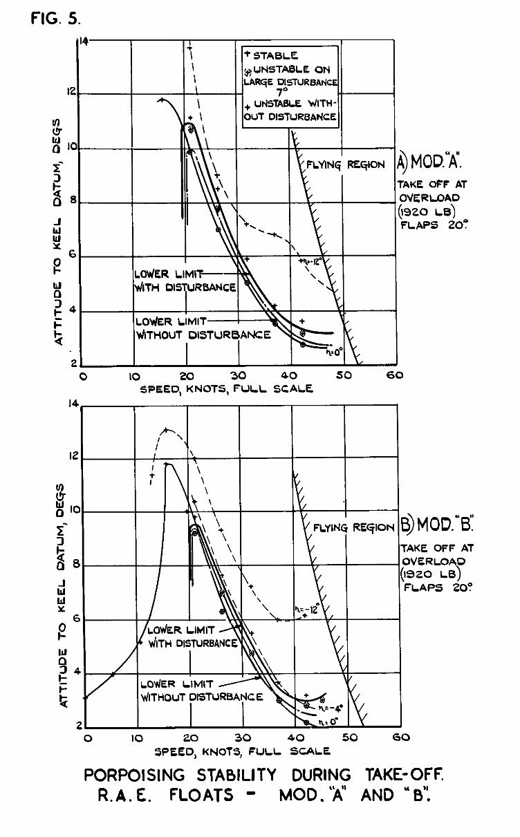
FIG 5.
+ UF(STABL2 WITH-
TAKE OFF AT
2 0 IO 20 30 40 50 60
SPEED, KNOTS, FULL SCALE
I I I I
TAKE OFF AT OVERLOAD )a20 LB) FLAPS 200
0 10 20 30 40 50 SPEED, KNOTS, FULL SCALE
60
PORPOISING STABILITY DURING TAKE-OFF R.A.E. FLOATS - MOD.%” AND “B’:
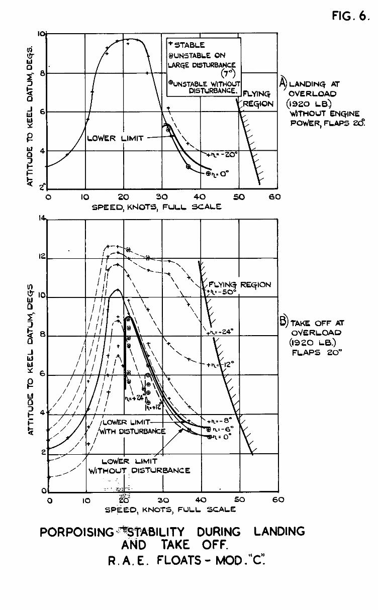
FIG. 6.
0 IO 20 30 40 50 60 SPEED, KdOTS, FULL SCALE
,- \I ,
/
c ,$ilTH DISTURBA /
t+ L t-
L
0 IO 33 30 40 50 60 SP’$ED, KNOTS, FULL SCALE
PORPOISING -*STABILITY DURING LANDING iH0 TAKE OFF.
R . A, E . FLOATS - MOD .“C’:
LAMDING AT OVERLOAD
(1920 LB) ~irHOU1 ENGINE POW&R, FLAPS Zd
TAKE OFF AT OVERLOAD (1920 1-6.) FLAPS 20”

A) AT TAKE OFF AT OVERLOAD.
20 30 40
e> STABILITY LIMITS DURING TAKE-OFF AT OVERLOAD WITHOUT DISTURBANCE.
r I I I I I I
\I \ I/MOD.%:’ I
.
SPEED,KNOlS, FULL SCALE ’ 2” I I I 1
20 30 40
C) STABILITY LIMITS DURING TAKE-OFF AT OVERLOAD WITH 7” DISTURBANCE.

FIG 8.
20 30 40 50 SPEED, Klr(OTS, FULL SCALE
A) COMPARISON OF ANGLES OF ELEVATOR AT STABILITY LIMITS WITH DISTURBANCE.
I - dt
i!I I 1 MObt’ WITH DISTURB I P . Cd 20 30 40 50
, SPEED, KNOTS, FULL SCALE
B) COMPARISON OF ELEVATOR SENSITIVITY AT STABILITY LIMITS WITH DISTURBANCE.
c( KEEL 4’ 5.3 KNOTT
G? KEEL 6.3’ IO.6 KNOTS
@. KEEL 14.1’ 15.9 KNOTS (HUMP STEED)
o( KEEL ibe0 21.2 KNOTS
ELEVAT ANGLO - ZE Y CHARACTERISTICS ON CAL
.A.E. GLOATS -
EEL E
ii ii.2 K!
EEL
12. f-30 - 300
CONSTANT SPEED
$OTS
9.6’ -300
KNOTS
o( KEEL 7.2” n=
d KEEL ta0 q = - 200
37.1 KNOTS
ACTER~STICS ON CAL ATE G AT LIGHT LOAD I720lb A.
.A.E. FLOATS - FI

a: KEEL 5.5 1\= 00

ACCELERATION d. KEEL 0.1s
CONSTANT SPEED
:EEL Io.e” - I20
KNOTS
d. KEEL IO’ h,” - 8”
26’5 KNOTS
e-i KEEL 5.6’ Q KEEL i fi’ .“*o b= -iP
37.1 KNOTS 42.3 KNOTS
r\ = - 40 31.7 KNOTS
SPRAY CHARACTERISTICS 0 G TAKE-OFF AT CJ .A.E. FLOATS - FI

flG. II.
IO
0.
I 5lABlLlTY LIMIT dlTH DlSTURBAtXE
5TABILltY LIMIT VhTHOUT DISTURBANCE
TAKE-OFF AT OVERLOAD
(IS20 LB> FLAPS 20’
0 IO 20 30 40 50 60 SPEED, KNOTS FULL SCALE.
WAVE TEST CONDITIONS
(ZERO WIND)
I
I

ACT~RlSTiCS I
LENGTH = 25 ft.,
c
FLOATS - “C’:

ACT~RIS~ICS I AVES.
HT = I .25 ft., GTH = 25 ft.,
0 co
IFICATI “C’.’

.
Y CHARACTE

7
FLOATS ” IFICATI “C’.’

. (7-J
RO
ODIFICATI “C:’

7
7
7
. FL. TS - IFICATI “C’.’

AVER,
HT = 2-i ft., LE
ZE c
IFICATI “C’.’

5 Y C~ARACTE VES,
.E. TS - IFIC “C’.’

SPRAY CHARACTERISTICS I
HEIGHT = 2.1 ft., LENGTH ,= 84 ft.,
ER
.A.E. FLOATS -

I
Ir* J
3
)
FIG. 15 8 lb.
I
I 100%
L 200% RESERVE OF 8UOYANCV
FIG. IS. VARIATION OF RESERVE OF BUOYANCY WITH STATIC BEAM LOADING COEFFICIENT.
---
11 11 11 11 03 0.4 0.5 06 07
a_ R c
FIG. 16. VARIATION OF DRAFT WITH ATTITUDE AND STATIC BfAM LOADING COEFFICIENT.

FIG. 17.

C.P. No. 15 2154
A.R.C. Technical Report
PuaLtsHED BY “ta t.5AmwY.s STATKINERY OFFlCE
To be purchased from York House, Kmgsway, LONDON, w c.2, 429 Oxford Street, LONDON, w 1,
P 0 Box 569. LONDON, s E 1, 13a Castle street, EDtNB”ROx, 2 1 St Andrew’s Crescent, CARDFF 39 Kmg street, MANCHFaTaa, 2 1 Tower Lane, BRKKIL, I
2 Edmund Street, BIRMINOHAM, 3 80 ChIchester Streef, BELFAST. or from any Bookseller I
1950 Price 5s. 6d. ner
I
S.O. Code No 23 - 9006 - 15