hydrocycle 9 pro vertical microgreen system (10')...microgreen system is important. check the...
TRANSCRIPT

1Revision date: 09.25.18
STK# DIMENSIONS
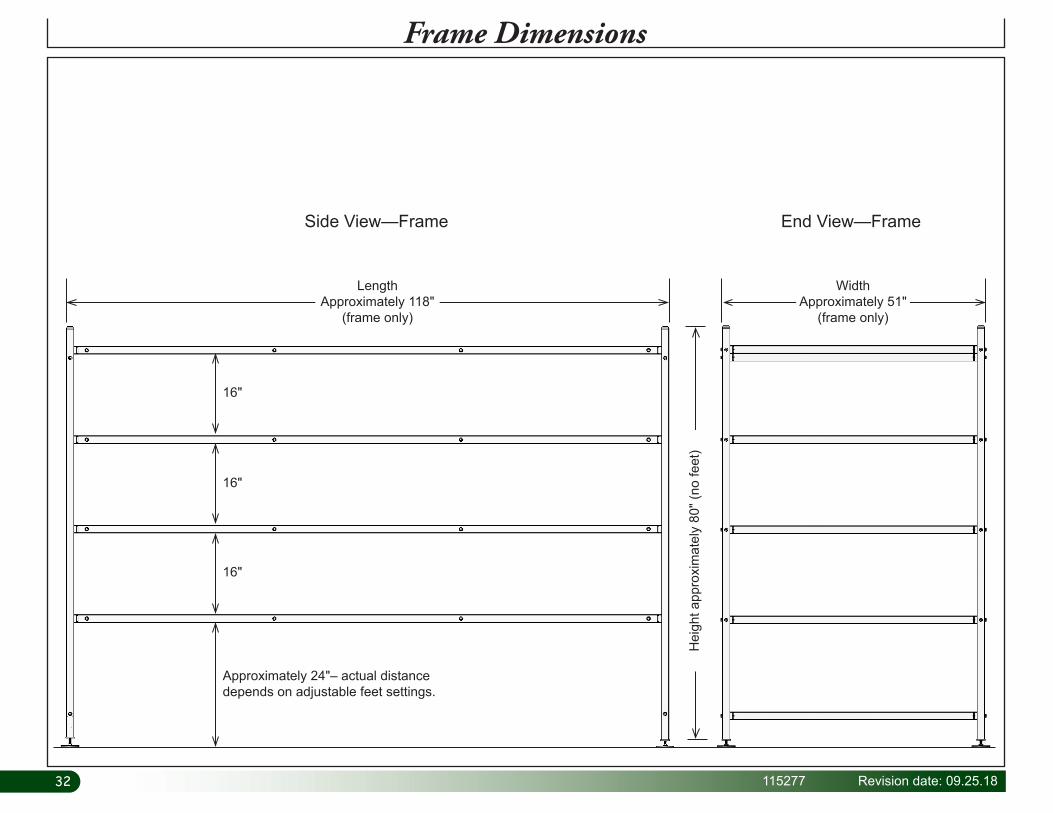
115277 51" W x 80" H x 118" L**Dimensions have been rounded and are approximate. Dimensions are of the frame only; they do not include adjustable feet or pvc plumbing and fixtures.
HydroCycle 9" Pro Vertical Microgreen
System (10')
©2018 Growers SupplyAll Rights Reserved. Reproduction is prohibited without permission.

2 115277 Revision date: 09.25.18
Important InformationREAD THIS DOCUMENT BEFORE YOU BEGINThank you for purchasing the vertical microgreen system. When properly assembled and maintained, this product will provide years of reliable service. These instructions include helpful hints and important information needed to safely assemble and properly maintain the system. Please read these instructions before you begin. If you have any questions during the assembly, contact Customer Service at 1.800.245.9881 for assistance.
ASSEMBLY PROCEDURE
Following the instructions as presented will help ensure the proper assembly of your microgreen system. The steps outlining the assembly process are as follows:
1. Verify that all parts are included in the shipment. Notify customer service for questions or concerns.
2. Read these instructions and all additional documentation included with the shipment before you begin.
3. Gather the tools and assistants.
4. For best results, assemble the components in the order they are presented in these instructions.
5. Read the care and maintenance information.
CARE AND MAINTENANCE
Proper care and maintenance of your microgreen system is important. Check the following items periodically to properly maintain your microgreen system.
• Check connections and all fasteners to verify that they remain tight.
• Do not climb or stand on the frame or channels at anytime.
• Verify that the supply lines and related fittings are clean and functioning properly.
• Replace all worn or damaged parts and fittings promptly.
• Repair all leaks immediately.
• If system is moved, inspect all parts and connections before reassembling and use.
• For replacement or missing parts, call 1.800.245.9881 for assistance.
SAFETY PRECAUTIONS
• Wear eye protection.
• Wear gloves when handling metal pipes.
• Use a portable GFCI (Ground Fault Circuit Interrupter) when working with power tools and cords.
UNPACK AND IDENTIFY PARTS
The following steps will ensure that you have all the necessary parts before you begin assembly.
1. Unpack the contents of the shipment and place where you can easily inventory the parts. Refer to the Bill of Materials/Spec Sheets.
2. Verify that all parts listed on the Bill of Materials/Spec Sheets are present. If anything is missing or you have questions, consult the Pictorial Parts Guide and all diagrams for clarification, or contact Customer Service.
NOTE: At this time, you do not need to open the plastic bags containing smaller parts such as fasteners or washers (if equipped).
QUICK START GUIDE For a quick overview of this product, its components, and connection details consult the Quick Start Guide at the back of these instructions.
REQUIRED TOOLS
The following list identifies the main tools needed to assemble the microgreen system. Additional tools and supports may be needed.
• Level (4'– recommended)
• Wrench set to set adjustable feet
• Ratchet with 1/2" socket to assemble frame
• 3/16" hex (Allen) wrench
• 5/16" drill bit
• Small hammer and gloves
• Cutting tool to cut pvc tubing
• Adjustable pliers
• 1-3/8", 2-1/4" and 2-1/2" hole saw bits
• Adjustable supports or saw horses for channel assembly.
WARNING: All electrical wiring to be completed by a qualified electrician and according to recongnized local building codes..

3Revision date: 09.25.18 115277
Important Information
PICTORIAL GUIDE
The following graphics and photos will help identify the different parts of the microgreen system. (Some parts may not be shown.) To prevent mixing of fittings, select only those that are needed for each procedure. Keep all fittings in the shipping bags until they are needed.
109242
112509 CA4000 Instant Adhesive
110829 Drill & Tap Combo Pak
112538 1" Hanger112539 2" Hanger
AC2804111047
111074
110725 Air Pump
113536 Pump
110091 Clear Vinyl Tubing
WR1095Tape
112838 Tek Screws
FALB34B
112772
112770
100442
113030S01112477
FAME51B FAG338B 110077
WF4790 (1)Key Punch
115 Gallon Reservoir
Porthole Cover
Reservoir Cover
ATTENTION: A timer is required to cycle the water pump on and off. If you did not purchase a timer, contact your sales representative to purchase the 112531 timer.
*Timer not included. Additional purchase required.112531 Timer*
4 115277 Revision date: 09.25.18
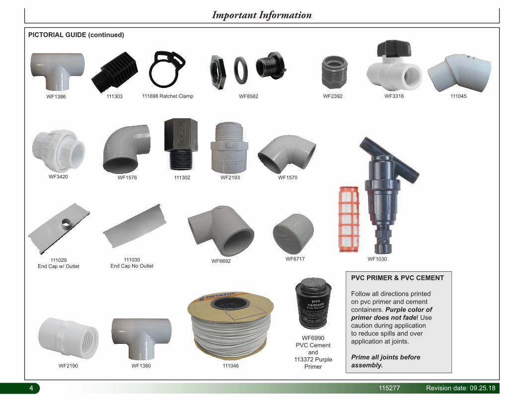
PICTORIAL GUIDE (continued)
Important Information
111303
WF3420 WF1576 111302 WF2193 WF1570
WF6717
WF3316 111045WF2392
WF2190 WF1380 111046
WF1030
111698 Ratchet Clamp
WF6692
WF1386 WF8582
111030End Cap No Outlet
111029End Cap w/ Outlet
WF6990PVC Cement
and113372 Purple
Primer
PVC PRIMER & PVC CEMENT
Follow all directions printed on pvc primer and cement containers. Purple color of primer does not fade! Use caution during application to reduce spills and over application at joints.
Prime all joints before assembly.

5Revision date: 09.25.18 115277
1Assemble Frame
ASSEMBLE SIDE FRAMES
Assemble frame on a flat, level surface for best results.
Complete these steps:
1. Review the frame diagram at the right (and at the back of this guide) and gather two (2) corner tubes and four (4) longer, side frame tubes to construct one side frame assembly.
2. Position the two (2) corner tubes so holes match up. The hole closest to the top end of each corner pipe is used to attach the upper side tube. Lower tier is approximately 23" from the end or bottom of the pipe. See diagram.
3. Take four (4) of the longer, side tubes and connect these to the corner tubes using the 112772 flat head bolts to assemble the first side frame.
4. With assistance, set the assembly aside and repeat the steps to assemble the remaining side frame.
5. Once both identical side frames are assembled, position these opposite each other. See diagram below.
6. Continue by installing the adjustable feet – Procedure 2.
Top view showing two assembled side frames.
112772 5/16" x 3" Flat
Head Bolt
Assembled Side Frame
Upper Tier
Lower Tier
115" Side TubeFD15LMGL11500S2
80" Corner TubeFD15VMGL08000S423"
ATTENTION: The vertical tubes include holes of two different diameters. Install the larger hole to the outside to allow the flat head bolt to sit flush with the tube surface when installed.
112772
Large hole to this side.

66 115277 Revision date: 09.25.18
STEP 4
Side Frame Assembly with Adjustable Feet
Cen
ter
ASSEMBLE FRAME—INSTALL ADJUSTABLE FEET
Assemble frame on a flat, level surface for best results.
2. Slide one 112477 insert assembly into the bottom of each 80" vertical leg tube. Tap gently with a small hammer if needed to seat.
3. Secure each insert to each tube using two (2) 112838 Tek screws. Install screws through leg tube and wall of the 112477 insert. Install screws to the left or right of the centerline of the leg tube to prevent hitting the threaded shaft of the adjustable foot.
4. Adjust the 113030S01 foot so that it is seated against the threaded plate of the insert and nut. See diagram.
5. Continue with the main frame assembly – Procedure 3.
Complete these steps:
1. Add one FALB34B nut to the threaded stud of each 113030S01 foot and attach one foot to each 112477 insert.
1Assemble Frame
112477
FALB34B
Bottom of Leg Tube
112477
FALB34B Locknut
113030S01
112838 Tek Screw
100442

7Revision date: 09.25.18 115277
ASSEMBLE FRAME—continued
Assemble frame on a flat, level surface for best results. Assistants are required to complete the frame assembly.
Complete these steps to assemble the main frame.
1. With assistance, stand the two side frames as shown (Fig. 1).
2. Select four (4) of the remaining frame tubes (FD15CMGL04800S1) and place two of these at each end of the side frames. FAME51B
FAG338B
FIG. 1
3. Using the FAG338B (5/16" x 3") hex head bolts and FAME51B flat washers, attach cross braces between side frame tubes (Fig. 2) at each end.
FIG. 2
48" Cross BraceFD15CMGL04800S1
48" Cross BraceFD15CMGL04800S1
FAG338B
FAME51B
1Assemble Frame

88 115277 Revision date: 09.25.18
ASSEMBLE FRAME—continued
4. Continue by installing all remaining cross braces between the side tubes at each level using the hex head bolts and flat washers.
5. Complete the frame assembly by installing the 112770 finishing plugs. Check all fasteners to ensure they are all tight.
6. Continue with the next procedure. FAME51B
FAG338B
112770FAG338B
FAME51B 112770
1Assemble Frame
9Revision date: 09.25.18 115277
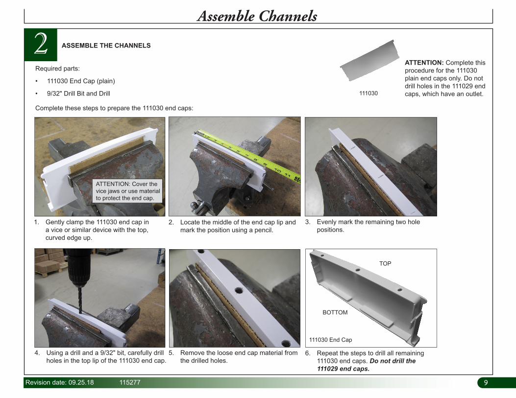
2Assemble Channels
Required parts:
• 111030 End Cap (plain)
• 9/32" Drill Bit and Drill
Complete these steps to prepare the 111030 end caps:
1. Gently clamp the 111030 end cap in a vice or similar device with the top, curved edge up.
2. Locate the middle of the end cap lip and mark the position using a pencil.
3. Evenly mark the remaining two hole positions.
4. Using a drill and a 9/32" bit, carefully drill holes in the top lip of the 111030 end cap.
5. Remove the loose end cap material from the drilled holes.
6. Repeat the steps to drill all remaining 111030 end caps. Do not drill the 111029 end caps.
ASSEMBLE THE CHANNELS
ATTENTION: Complete this procedure for the 111030 plain end caps only. Do not drill holes in the 111029 end caps, which have an outlet.
ATTENTION: Cover the vice jaws or use material to protect the end cap.
111030 End Cap
111030
TOP
BOTTOM
1010 115277 Revision date: 09.25.18
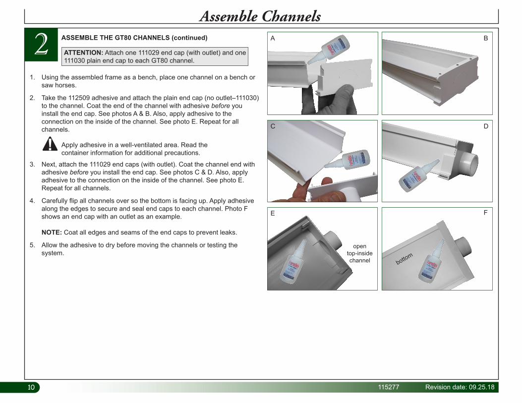
21. Using the assembled frame as a bench, place one channel on a bench or
saw horses.
2. Take the 112509 adhesive and attach the plain end cap (no outlet–111030) to the channel. Coat the end of the channel with adhesive before you install the end cap. See photos A & B. Also, apply adhesive to the connection on the inside of the channel. See photo E. Repeat for all channels.
ASSEMBLE THE GT80 CHANNELS (continued)
3. Next, attach the 111029 end caps (with outlet). Coat the channel end with adhesive before you install the end cap. See photos C & D. Also, apply adhesive to the connection on the inside of the channel. See photo E. Repeat for all channels.
4. Carefully flip all channels over so the bottom is facing up. Apply adhesive along the edges to secure and seal end caps to each channel. Photo F shows an end cap with an outlet as an example. NOTE: Coat all edges and seams of the end caps to prevent leaks.
5. Allow the adhesive to dry before moving the channels or testing the system.
Apply adhesive in a well-ventilated area. Read the container information for additional precautions.
ATTENTION: Attach one 111029 end cap (with outlet) and one 111030 plain end cap to each GT80 channel.
A B
C D
open top-inside channel bottom
E F
Assemble Channels

11Revision date: 09.25.18 115277
Complete these steps.
1. Determine which direction you want the drain manifold to slope toward and attach the high end pipe hanger first. See A. NOTE: Attach 112539 hanger flush with the top edge of the channel support tube and flush with the inside edge vertical frame tube. Secure hangers to the frame using 112838 Tek screws and the 100442 driver.
3 INSTALL 2" DRAIN MANIFOLD HANGERS
112539 2" Hanger100442
Nut Setter112838
Tek Screw
Install 2" Pipe Hangers
Attach 112539 hangers here.
Channel Support Tube
Horizontal Frame Brace
Horizontal Frame Brace
Channel Support Tube
Channel Support Tube
Channel Support Tube
End View of Main Frame
A B
Low End of Drain Manifold
1/4" to 3/8" down from top of tube.
Install hanger flush to inside of vertical tube.
B
Verti
cal T
ube
Install hanger flush to inside of vertical tube.
Install hanger flush to top of support tube.
High End of Drain Manifold
A
Support Tube
Verti
cal T
ube
2. Move to the low end and attach hangers 1/4" down from the top edge of the support tube and flush to the inside of the vertical frame tube. See B.
3. Repeat for all remaining 2" drain hangers.
Low End
High End
Drain this direction.
Frame brace is not shown.
1212 115277 Revision date: 09.25.18
Diagram shows pvc tube with drilled drain holes and channels on support tube. Channels are added in a later procedure.
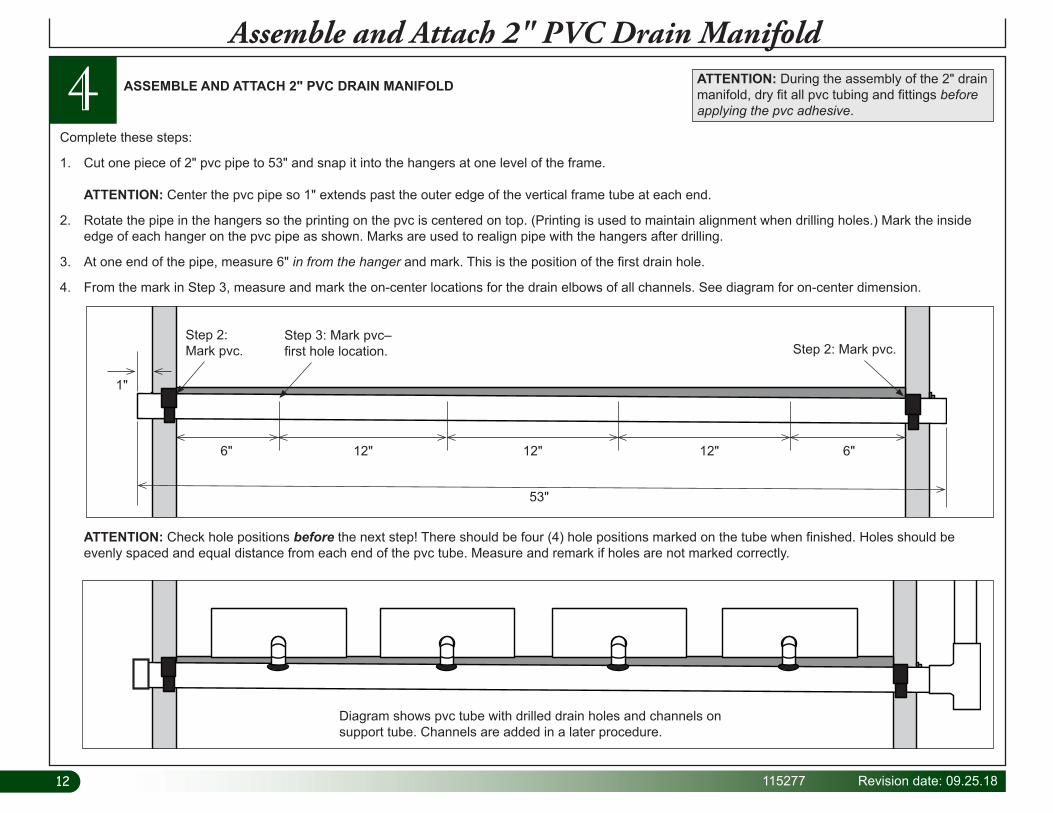
4 ASSEMBLE AND ATTACH 2" PVC DRAIN MANIFOLD
Assemble and Attach 2" PVC Drain ManifoldATTENTION: During the assembly of the 2" drain manifold, dry fit all pvc tubing and fittings before applying the pvc adhesive.
Complete these steps:
1. Cut one piece of 2" pvc pipe to 53" and snap it into the hangers at one level of the frame. ATTENTION: Center the pvc pipe so 1" extends past the outer edge of the vertical frame tube at each end.
2. Rotate the pipe in the hangers so the printing on the pvc is centered on top. (Printing is used to maintain alignment when drilling holes.) Mark the inside edge of each hanger on the pvc pipe as shown. Marks are used to realign pipe with the hangers after drilling.
3. At one end of the pipe, measure 6" in from the hanger and mark. This is the position of the first drain hole.
4. From the mark in Step 3, measure and mark the on-center locations for the drain elbows of all channels. See diagram for on-center dimension.
53"
6" 6"12" 12" 12"
1"
Step 2: Mark pvc.
Step 3: Mark pvc–first hole location. Step 2: Mark pvc.
ATTENTION: Check hole positions before the next step! There should be four (4) hole positions marked on the tube when finished. Holes should be evenly spaced and equal distance from each end of the pvc tube. Measure and remark if holes are not marked correctly.

13Revision date: 09.25.18 115277
5. After confirming hole positions, use a 1-3/8" hole saw bit to drill the four (4) holes in the 2" tube. Example shows using a step bit to drill the holes. Keep all holes aligned during this step. Use the printing on the pipe if possible. NOTE: Pvc pipe can remain clamped in the hangers, or it can be removed and drilled off the rack. If you leave it clamped to the rack, block the center of the pipe or have an assistant hold it to prevent damage to the pipe hangers. For best results, drill pvc in a drill press if possible. To release the pvc pipe from the clamps, press the pipe into the hanger and use a small screw driver to release the hanger jaws. Hangers will release easily. Be careful not to damage the locking teeth of the hanger jaws.
4Assemble and Attach 2" PVC Drain Manifold
Center Line
Photo shows using a step bit to drill holes in the pvc pipe.
Photo shows using a hole saw bit to drill holes in pvc pipe.
6. After drilling the pipe, remove all pvc debris and clean inside the tube. If pipe was drilled on the rack, remove it from the lower level and install at the upper level after cleaning. Use the lower level hangers to hold and drill the pipe. Diagram below shows top view of pvc pipe after drilling drain holes.
Place a 2" x 4" under the center to brace pipe if drilling holes when attached to hangers.
7. Repeat these steps to prepare, drill, and clean the remain three (3) horizontal 2" pvc drain pipes.
ASSEMBLE AND ATTACH 2" PVC DRAIN MANIFOLD—continued
1414 115277 Revision date: 09.25.18
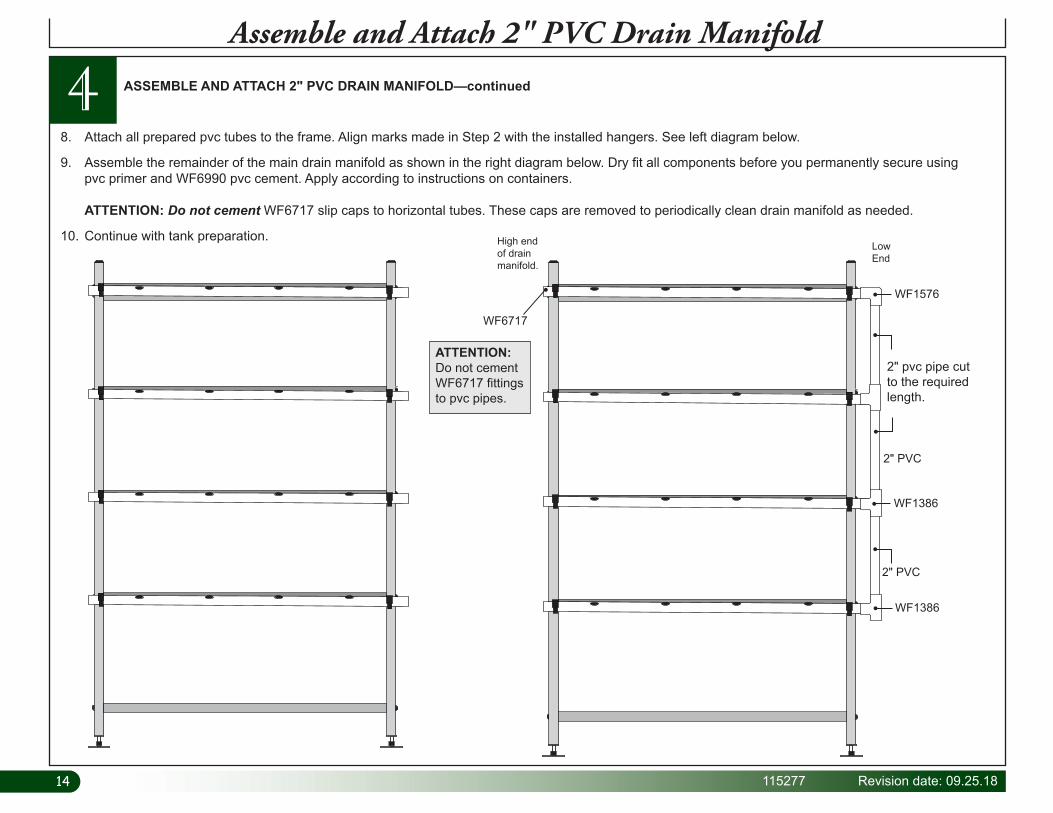
4 ASSEMBLE AND ATTACH 2" PVC DRAIN MANIFOLD—continued
Assemble and Attach 2" PVC Drain Manifold
High end of drain manifold.
Low End
2" pvc pipe cut to the required length.
WF1386
WF1386
WF1576
WF6717
2" PVC
2" PVC
8. Attach all prepared pvc tubes to the frame. Align marks made in Step 2 with the installed hangers. See left diagram below.
9. Assemble the remainder of the main drain manifold as shown in the right diagram below. Dry fit all components before you permanently secure using pvc primer and WF6990 pvc cement. Apply according to instructions on containers. ATTENTION: Do not cement WF6717 slip caps to horizontal tubes. These caps are removed to periodically clean drain manifold as needed.
10. Continue with tank preparation.
ATTENTION: Do not cement WF6717 fittings to pvc pipes.

15Revision date: 09.25.18 115277
1. Identify corner you want to drill the drain hole in reservoir lid. (When reservoir is in position under frame, this is the corner closest to drain manifold.) Drill drain hole using a 2-1/2" hole saw. Do not drill cover over the reservoir. Debris can damage the pump and clog the filter once system is operating.
2. Next, using a 5/16" drill bit, drill hole through the lid for the air pump tubes. See photo below.
STEP 1: X marks hole location based on reservoir design and position. Drill one 2-1/2" drain hole in corner.
STEP 2: Drill holes for air pump tubes using a 5/16" drill bit. Drill cover off reservoir.
Photo show drain hole in reservoir lid.
Move cover off reservoir. Place on support to drill the 2-1/2" drain hole.
Photo shows sample reservoir with drain hole in lid. Actual lid and reservoir may differ.
x
Actual lid and reservoir may differ slightly from what is shown in this example.
2-1/2" Drain Pipe Hole
5 DRILL RESERVOIR AND LID AND INSTALL FITTINGS
Reservoir and Lid Preparation
Required tools: Drill, 5/16" drill bit, 2-1/4" and 2-1/2" hole saw bits
ATTENTION: Actual reservoir and lid may differ from the model used in the photos. Procedures are similar.

1616 115277 Revision date: 09.25.18
5 DRILL RESERVOIR AND LID AND INSTALL FITTINGS—continued
Reservoir and Lid Preparation
3. Finally, take the reservoir and drill the bulkhead fitting hole using a 2-1/4" hole saw bit. Review photos and diagrams for position. ATTENTION: Use the pump to determine the hole position on the reservoir. Set the pump and reservoir on the same level surface and align the inlet port of the pump with the spot on the reservoir where the bulkhead fitting will be installed. Mark the location. Adjust as needed to ensure the entire bulkhead fitting is against the flat surface of the reservoir. Dashed line outlines area for bulkhead fitting.
4. Attach the WF2392 bushing, 111302 extension, and 111303 screen to the threaded body of the bulkhead fitting. Hand tighten until snug.
5. Attach the bulkhead assembly to the reservoir. Hex nut and thin flat washer are outside the reservoir. Tighten until snug using large adjustable pliers.
6. Continue with the next procedure.
WF2392 Bushing
111303 Screen
111302
Install rubber seal inside reservoir.
Inside reservoir photo showing fittings.
Sample Reservoir
Identify hole position. Use inlet side of pump to determine the center of the bulkhead fitting. REMEMBER: Entire bulkhead must remain within the flat surface of the reservoir.
WF8582 Bulkhead Fitting Installed
Install hex nut and flat washer outside reservoir.
Step 3
17Revision date: 09.25.18 115277
6 ASSEMBLE AND INSTALL NUTRIENT SUPPLY MANIFOLDS
Assemble and Install Nutrient Supply Manifold
Complete these steps:
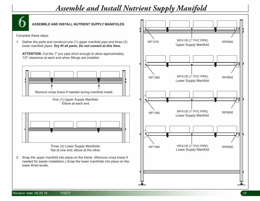
1. Gather the parts and construct one (1) upper manifold pipe and three (3) lower manifold pipes. Dry fit all parts. Do not cement at this time. ATTENTION: Cut the 1" pvc pipe short enough to allow approximately 1/2" clearance at each end when fittings are installed.
One (1) Upper Supply Manifold: Elbow at each end.
Three (3) Lower Supply Manifolds: Tee at one end; elbow at the other.
WF1380
WF1380
WF1380
WF4135 (1" PVC PIPE)
WF4135 (1" PVC PIPE)
WF4135 (1" PVC PIPE)
WF4135 (1" PVC PIPE)
WF1570 WF6692
WF6692
WF6692
WF6692
Upper Supply Manifold
Lower Supply Manifold
Lower Supply Manifold
Lower Supply Manifold
2. Snap the upper manifold into place on the frame. (Remove cross brace if needed for easier installation.) Snap the lower manifolds into place on the lower three levels.
Remove cross brace if needed during manifold install.

1818 115277 Revision date: 09.25.18
6Assemble and Install Nutrient Supply Manifold
3. Align and evenly space all channels at each level. Channels will run parallel with each other and the 55" frame tubes. Insert drain elbows into drain manifold to keep channels in place.
4. With all manifolds snapped into place on the frame, mark the center of each manifold along its length using a chalk line. You can also rotate the pvc pipe so the printing shows. Use non-permanent chalk.
5. Using a marker, mark three (3) hole locations on each manifold pipe for each channel. Mark holes in the center of the manifold pipe. Space holes 3" apart.
6. After holes are marked, mark each fitting to more easily reassemble the manifolds after drilling the holes and cleaning the pipe.
7. Once the manifolds are marked, carefully remove each manifold from the frame. Use a small screwdriver to carefully release the jaws of the pipe hangers. If desired, mark the frame level (1, 2, or 3) on each of the lower manifolds to reinstall them in the same location.
Step 5: 3" Hole Spacing
Step 6: Mark fitting positions for reassembly.
Mark here to keep fitting in the same place.
Step 4: Mark center of each pipe.
Remove frame cross brace to install manifold.
ASSEMBLE AND INSTALL NUTRIENT SUPPLY MANIFOLDS—CONTINUED
Chalk line
Align center hole for each channel with center of channel.

19Revision date: 09.25.18 115277
6Assemble and Install Nutrient Supply Manifold
8. Choose one manifold and place it on a flat surface with the marks facing up. Upper manifold is shown below.
9. Using the drill bit from the 110829 drill and tap combo pak, drill a hole at each of the marks. For best results, drill the manifold using a drill press. Repeat this step to drill the remaining supply manifolds.
10. After drilling the holes in all manifolds, use the tap from the combo pak to tap threads in each hole. Use a reversible drill. Do not use a drill press. Slowly turn tap into the hole. Do not allow it to bottom out in the pvc tube. After tapping the hole, reverse the drill and back the tap out. Keep the drill steady and straight during this process. ATTENTION: Use a reversible, variable speed drill for this step! If one is not available, use a socket to hold the tap and turn it with a ratchet. Center tap in the hole and turn it slowly to tap threads. Do not allow tap to contact the inside wall of the pvc tube. Once threads are tapped, slowly back tap out of hole while keeping drill straight.
Tighten tap in drill chuck.
110829 Drill & Tap
Combo Pak
11. Next, disassemble each manifold and clean the pvc pipe to remove debris from inside the tube. Keep parts for each manifold together.
ASSEMBLE AND INSTALL NUTRIENT SUPPLY MANIFOLDS—CONTINUED

2020 115277 Revision date: 09.25.18
6Assemble and Install Nutrient Supply Manifold
12. Wrap the threaded end of each 109242 adapter three or four times with the WR1095 tape. Wrap in a direction that will not loosen when adapter is installed. There are 48 adapters needed for this system.
Install adapters using WF4790 key punch. Wrap threads of adapters with tape.
13. Using the WF4790 key punch, carefully install the adapters in each of the manifold pipes. Do not overtighten! Adapters will snap off. Once slight resistance is felt during installation, stop tightening the adapter.
14. Apply pvc primer and cement to each end of one manifold pipe and fittings. Reassemble manifold using fittings for that pipe. Use the marks to position the fittings as they were before manifold was disassembled. Set the assembly aside and repeat the step to reassemble all manifolds. Allow cement to set before continuing with the next step.
ASSEMBLE AND INSTALL NUTRIENT SUPPLY MANIFOLDS—CONTINUED109242
Adapters
WR1095Tape
WF4790Key Punch
Alignment Marks
PVC Primer & Cement PVC Primer & Cement
21Revision date: 09.25.18 115277
6Assemble and Install Nutrient Supply Manifold
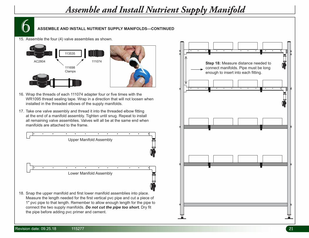
15. Assemble the four (4) valve assemblies as shown.
16. Wrap the threads of each 111074 adapter four or five times with the WR1095 thread sealing tape. Wrap in a direction that will not loosen when installed in the threaded elbows of the supply manifolds.
17. Take one valve assembly and thread it into the threaded elbow fitting at the end of a manifold assembly. Tighten until snug. Repeat to install all remaining valve assemblies. Valves will all be at the same end when manifolds are attached to the frame.
AC2804 111074
113535
111698 Clamps
18. Snap the upper manifold and first lower manifold assemblies into place. Measure the length needed for the first vertical pvc pipe and cut a piece of 1" pvc pipe to that length. Remember to allow enough length for the pipe to connect the two supply manifolds. Do not cut the pipe too short. Dry fit the pipe before adding pvc primer and cement.
Upper Manifold Assembly
Lower Manifold Assembly
Step 18: Measure distance needed to connect manifolds. Pipe must be long enough to insert into each fitting.
ASSEMBLE AND INSTALL NUTRIENT SUPPLY MANIFOLDS—CONTINUED
2222 115277 Revision date: 09.25.18
6Assemble and Install Nutrient Supply Manifold
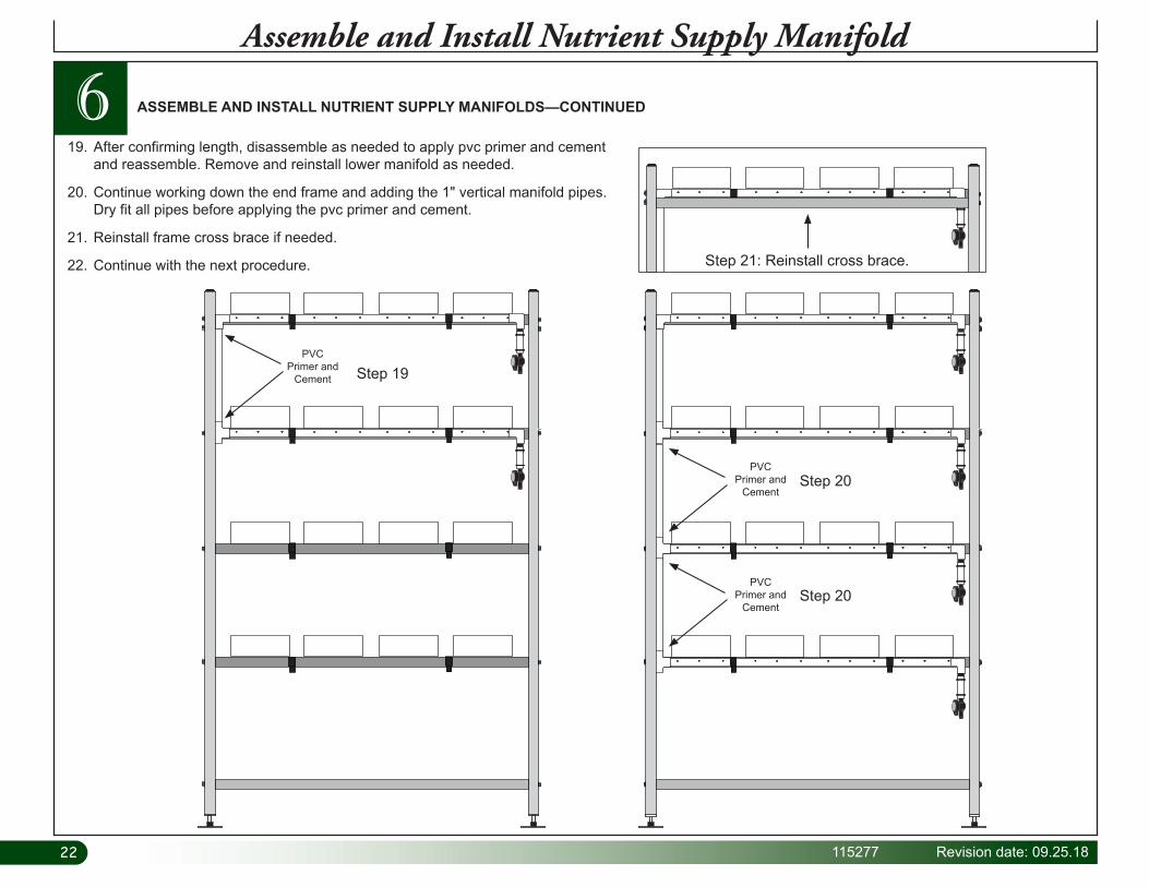
19. After confirming length, disassemble as needed to apply pvc primer and cement and reassemble. Remove and reinstall lower manifold as needed.
20. Continue working down the end frame and adding the 1" vertical manifold pipes. Dry fit all pipes before applying the pvc primer and cement.
21. Reinstall frame cross brace if needed.
22. Continue with the next procedure.
Step 19
Step 20
Step 20
Step 21: Reinstall cross brace.
ASSEMBLE AND INSTALL NUTRIENT SUPPLY MANIFOLDS—CONTINUED
PVC Primer and
Cement
PVC Primer and
Cement
PVC Primer and
Cement
23Revision date: 09.25.18 115277
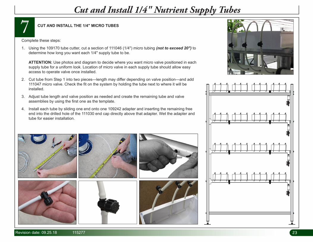
7Cut and Install 1/4" Nutrient Supply Tubes
Complete these steps:
1. Using the 109170 tube cutter, cut a section of 111046 (1/4") micro tubing (not to exceed 20") to determine how long you want each 1/4" supply tube to be. ATTENTION: Use photos and diagram to decide where you want micro valve positioned in each supply tube for a uniform look. Location of micro valve in each supply tube should allow easy access to operate valve once installed.
2. Cut tube from Step 1 into two pieces—length may differ depending on valve position—and add 111047 micro valve. Check the fit on the system by holding the tube next to where it will be installed.
3. Adjust tube length and valve position as needed and create the remaining tube and valve assemblies by using the first one as the template.
4. Install each tube by sliding one end onto one 109242 adapter and inserting the remaining free end into the drilled hole of the 111030 end cap directly above that adapter. Wet the adapter and tube for easier installation.
CUT AND INSTALL THE 1/4" MICRO TUBES

2424 115277 Revision date: 09.25.18
Complete these steps:
1. Move the frame to the location where it will be used if needed.
2. At the drain (low) end of the frame, adjust the adjustable feet to lower that end of the frame as much as possible. Allow enough room between the top of each foot and the locking nut to make final adjustments and to lock the feet in position. Set a level on the lower frame cross brace and check. Adjust side-to-side frame position so frame is level. See end frame diagram below.
3. Move to the supply end of the frame and raise that end to achieve the required slope.
4. Level the frame side-to-side after setting end-to-end slope.
5. Recheck the frame slope. Verify that ends are level. Tighten the lock nuts to secure feet.
8 LEVEL FRAME AND SET SLOPE
Level Frame and Set Slope
To ensure that water flows through and properly drains from the plant channels, a 1/2" slope toward the drain end of the system is required. Frame must also be level from side-to-side when viewed from the end.
ATTENTION: Example below shows a system setting on a level finished grade. If finished grade is sloped, make the necessary adjustments in the calculations to account for any differences. When slope is properly set, frame should slope 1/2" from the supply end down toward the drain end.
Adjust slope as needed to achieve desired results.
Drain Drain
Finished Grade
X"X" + 1/2"
Drain End
End View

25Revision date: 09.25.18 115277
9 INSTALL THE MAIN PUMP & PLUMBING
Install the Main Pump and Plumbing
• Dry fit all connections before applying pvc primer and cement.
• Install the WF1030 Y-filter with the water-flow direction arrow pointing away from the pump.
• Center reservoir so bulkhead fitting points toward the supply manifold end of the frame.
Gather parts identified in the photo and construct main pump supply plumbing. Review assembly and installation notes that follow before you begin. For best results, complete this procedure after setting frame slope. WARNING: All electrical
wiring to be completed by a qualified electrician according to recognized local building codes.
WF1570
From
Pum
p
WF1570 WF2190111045
WF2190WF3420WF6682
WF1030
WF3420
1" PVC1" PVC WF1380 tee
fitting at the end of the pvc manifold.
Water Flow
A See A in diagram below.
WF1570water flow
Supply Manifold
End
1/4" Nutrient
Tube
Drain Manifold
End
2" Drain PVC
Reservoir
113536 Pump
113537 Unions
A
Side View of System
Drain Drain
NOTE: Secure pump to mounting surface to reduce vibration.
See A in diagram above.
Bulkhead Fitting & WF2193 Adapter

2626 115277 Revision date: 09.25.18
10 ASSEMBLE AND ATTACH PVC DRAIN MANIFOLD
Complete these steps:
1. Measure, cut, and dry fit the remaining sections of the 2" pvc drain manifold as shown in the photos below.
2. Once the fit is confirmed, disassemble and apply pvc primer and WF6990 cement to drain tubes and fittings. See below. ATTENTION: Do not cement the extension tube that extends through the lid from the WF1576 elbow. Extension tube must remain free to remove for routine tank maintenance.
3. Allow the cement to set and continue with following procedure.
Assemble and Attach 2" PVC Drain Manifold
WF1576
Minimum 6" tube. Tube should extend through lid at least 2" but remain above solution level.
WF1576
2" PVC
2" PVC
WF1576
No Cement!
Cement
Cement
WF1576 WF1576
A
A

27Revision date: 09.25.18 115277
11For optimal system performance and to extend the life of the nutrient solution through increased oxygenation, an aerator pump and aerator stones are included. Position stones at the bottom of the reservoir opposite the water pump. Air pump must remain above nutrient level to prevent siphoning.
1. Choose a position for the air pump and use it to determine the length of each air tube. Cut two air tubes of equal length using the 110091 tubing. ATTENTION: Position the air pump at a level that is above the nutrient level at all times to prevent siphoning of the reservoir in the event of a power outage.
2. Attach one stone to each line and set the stones in the reservoir. See photo for stone position opposite the water pump.
3. Place the reservoir cover on the reservoir and feed the tubing up through the access holes and connect the free end of each tube to the air pump.
ATTENTION: Always position the air pump above the nutrient level to prevent siphoning of the reservoir.
ATTACH THE AIR PUMP AND AERATOR STONES
Attach 110091 tube to air stone.
110077 Air Stone
4. Place the air pump in the position chosen in Step 1.
5. Connect the air pump to power and test the operation. Verify that air is filtering through each air stone. Monitor the air pump regularly to ensure proper operation of the aerator system. NOTE: When the system is fully operational, the air pump will run continuously. Do not connect the air pump to any circuit controlled by a timer or shutoff switch.
6. After testing air flow, turn off the aerator pump until the system is fully functional.
Install the Air Pump and Tubing
Air Tube
2828 115277 Revision date: 09.25.18
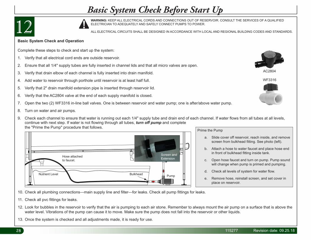
12Basic System Check Before Start Up
Basic System Check and Operation
Complete these steps to check and start up the system:
1. Verify that all electrical cord ends are outside reservoir.
2. Ensure that all 1/4" supply tubes are fully inserted in channel lids and that all micro valves are open.
3. Verify that drain elbow of each channel is fully inserted into drain manifold.
4. Add water to reservoir through porthole until reservoir is at least half full.
5. Verify that 2" drain manifold extension pipe is inserted through reservoir lid.
6. Verify that the AC2804 valve at the end of each supply manifold is closed.
7. Open the two (2) WF3316 in-line ball valves. One is between reservoir and water pump; one is after/above water pump.
8. Turn on water and air pumps.
9. Check each channel to ensure that water is running out each 1/4" supply tube and drain end of each channel. If water flows from all tubes at all levels,
10. Check all plumbing connections—main supply line and filter—for leaks. Check all pump fittings for leaks.
11. Check all pvc fittings for leaks.
12. Look for bubbles in the reservoir to verify that the air is pumping to each air stone. Remember to always mount the air pump on a surface that is above the water level. Vibrations of the pump can cause it to move. Make sure the pump does not fall into the reservoir or other liquids.
13. Once the system is checked and all adjustments made, it is ready for use.
WARNING: KEEP ALL ELECTRICAL CORDS AND CONNECTIONS OUT OF RESERVOIR. CONSULT THE SERVICES OF A QUALIFIED ELECTRICIAN TO ADEQUATELY AND SAFELY CONNECT PUMPS TO POWER.
ALL ELECTRICAL CIRCUITS SHALL BE DESIGNED IN ACCORDANCE WITH LOCAL AND REGIONAL BUILDING CODES AND STANDARDS.
WF3316
AC2804
Prime the Pump
a. Slide cover off reservoir, reach inside, and remove screen from bulkhead fitting. See photo (left).
b. Attach a hose to water faucet and place hose end in front of bulkhead fitting inside tank.
c. Open hose faucet and turn on pump. Pump sound will change when pump is primed and pumping.
d. Check all levels of system for water flow.
e. Remove hose, reinstall screen, and set cover in place on reservoir.
Nutrient Level
Screen and ExtensionHose attached
to faucet.
Bulkhead Pump
continue with next step. If water is not flowing through all tubes, turn off pump and complete the "Prime the Pump" procedure that follows.

29Revision date: 09.25.18 115277
Operational and Maintenance InformationGeneral Cleaning and Maintenance Instructions
For optimal performance and to increase yields, check and clean the system periodically. Time between maintenance and cleaning depends on the growing environment and specific use of the system. Complete the following steps as needed to ensure that your system is working properly.
1. Inspect the frame and mounting screws to ensure they are tight and frame is not damaged.
2. Disconnect the main power supply to turn off all pumps. Remove the reservoir cover and inspect the inside of the reservoir. Reservoir should be cleaned each time the nutrient solution is changed. Keep the reservoir and porthole covers in place during operation to prevent light from entering the reservoir.
3. Check all plumbing and main supply connections to ensure that all are operating as designed. No leaks.
4. Replace worn or cracked supply tubes as needed.
5. Clean the drain tube if needed. Remove the end plugs and inspect the inside of the tube. Clean the drain tube by pulling or pushing a brush or cloth through the it. Rinse with clean water. NOTE: Do not allow debris from the drain tube to contaminate the contents of the reservoir. Remove extension tube before cleaning.
6. With the pump off, disassemble the filter and clean the screen and housing. Reassemble for use. See procedure in the right column.
For best results, clean the filter screen regularly or when the flow rate changes unexpectedly. Complete these steps to clean the filter screen.
1. Shutoff the power to the nutrient pump. Open the valve on the filter to drain into a bucket.
2. Grip the filter housing and the main supply line and unscrew the housing. Do not apply force to the filter fittings.
Clean the Filter Screen and Housing
3. Remove the screen from the housing. Using clean water, rinse the housing and the screen.
4. Insert the screen back into the housing, reassemble the filter, and close the valve.
5. Turn on the pump and check the flow from the supply tubes to each channel.
6. Check filter and fittings for leaks.
Flow Flow
ATTENTION: Actual system may differ from the example shown. Photos are provided for filter cleaning only. They do not shown actual system.

30 115277 Revision date: 09.25.18
Clean the reservoir periodically to maximize plant growth and to minimize system contamination. The steps that follow can be used to change nutrient solution and to pump the reservoir for cleaning and typical maintenance. Cleaning the filter is strongly recommended after cleaning the reservoir.
RESERVOIR CLEANING AND MAINTENANCE
1. Turn off the nutrient pump and connect a garden hose to the shutoff valve of the filter. Place the end of the hose in a bucket or run it to the desired location.
2. Open the shutoff valve on the filter and turn the pump on to pump out the reservoir. Turn off the pump once the reservoir is empty.
3. Clean reservoir. Repeat steps to pump it out if needed.
4. Close the shutoff valve.
5. Remove the hose and clean the filter. See previous page for filter cleaning procedure.
6. Refill the reservoir with nutrient solution. Turn on the pump to resume operation. Check all fittings, tubes, and filter for leaks.
Shutoff Valve
Operational and Maintenance Information

31Revision date: 09.25.18 115277
Quick Start GuideSample System — Fully Assembled ATTENTION: A timer is required
to cycle the water pump on and off. If you did not purchase a timer, contact your sales representative to purchase the 112531 timer.
*Timer not included. Additional purchase required.
When set properly, the timer will allow pump to run long enough to ensure plants (and growing media) receive adequate nutrient solution each level.
Do not over water or allow growing media, seeds, or plants to dry out.
Adjust water flow as needed to prevent washing seeds out of NFT channels and into reservoir.
112531 Timer*
32 115277 Revision date: 09.25.18
Hei
ght a
ppro
xim
atel
y 80
" (no
feet
)
Width Approximately 51"
(frame only)
End View—Frame
Length Approximately 118"
(frame only)
Side View—Frame
Approximately 24"– actual distance depends on adjustable feet settings.
16"
16"
16"
Frame Dimensions
33Revision date: 09.25.18 115277
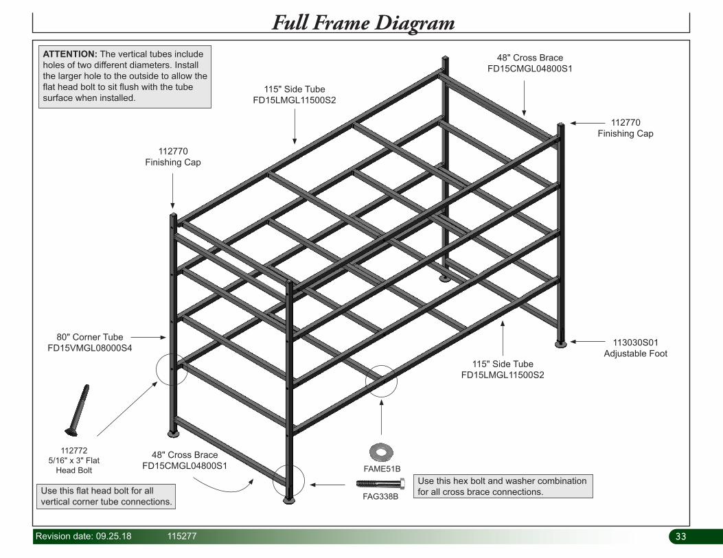
Full Frame Diagram
48" Cross Brace FD15CMGL04800S1
48" Cross Brace FD15CMGL04800S1
112770Finishing Cap
112770Finishing Cap
115" Side TubeFD15LMGL11500S2
113030S01Adjustable Foot
115" Side TubeFD15LMGL11500S2
80" Corner TubeFD15VMGL08000S4
112772 5/16" x 3" Flat
Head Bolt FAME51B
FAG338B
Use this hex bolt and washer combination for all cross brace connections.Use this flat head bolt for all
vertical corner tube connections.
ATTENTION: The vertical tubes include holes of two different diameters. Install the larger hole to the outside to allow the flat head bolt to sit flush with the tube surface when installed.

34 115277 Revision date: 09.25.18
Supply & Drain Manifolds Only
Drain
Supply
35Revision date: 09.25.18 115277
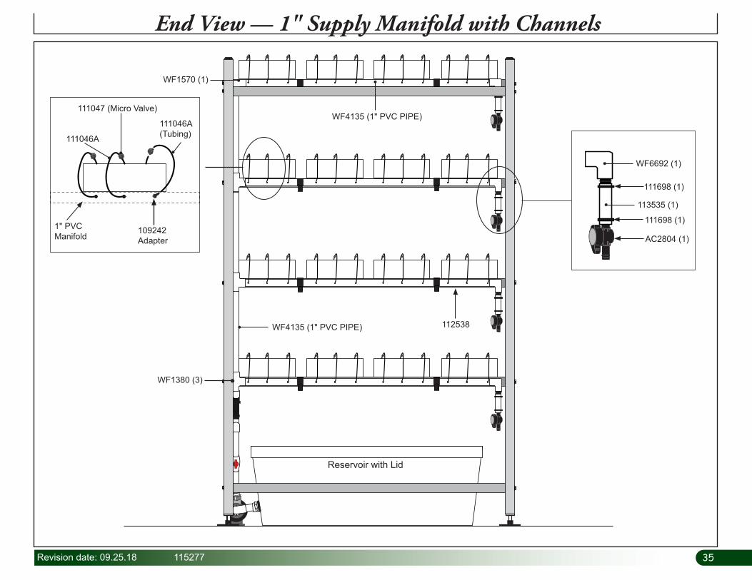
End View — 1" Supply Manifold with Channels
112538
WF1380 (3)
WF4135 (1" PVC PIPE)
WF4135 (1" PVC PIPE)
WF1570 (1)
111698 (1)
111698 (1)
113535 (1)
WF6692 (1)
AC2804 (1)
111047 (Micro Valve)
111046A (Tubing)111046A
109242 Adapter
1" PVC Manifold
Reservoir with Lid
36 115277 Revision date: 09.25.18
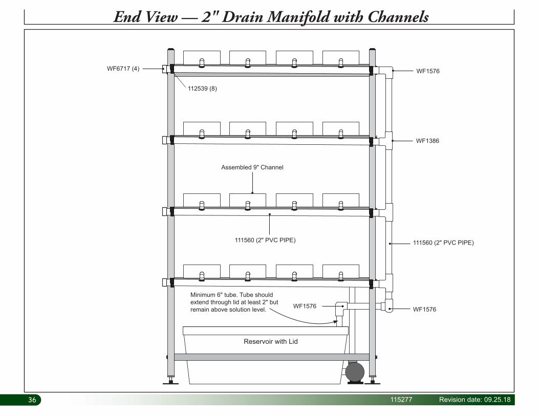
End View — 2" Drain Manifold with Channels
WF1576
WF1576
WF1386
WF6717 (4)
Assembled 9" Channel
112539 (8)
WF1576
111560 (2" PVC PIPE) 111560 (2" PVC PIPE)
Reservoir with Lid
Minimum 6" tube. Tube should extend through lid at least 2" but remain above solution level.

37Revision date: 09.25.18 115277
Side View with Channels
113537
WF3316
WF3420
111045111045
WF1380
WF1030
113536
WF2190
Bulkhead Fitting & WF2193 Adapter

38 115277 Revision date: 09.25.18
Additional Photos — Supply Manifold and Pump
ATTENTION: WF3316 valves are shown in the "closed" position to remove pump.
Both WF3316 valves to remain open during operation.
WF3316
ATTENTION: WF3316 valves are shown in the "open" position during system operation. Never close valves when system is in use.
Actual tank and pump may differ from example shown.
ATTENTION: Actual tank may differ from example shown. Pipe length and position of components depends on assembly. Completed assembly of actual system may differ from the example shown in photos throughout this guide.
ATTENTION: Pump shown may differ from actual pump. Connections and valves are the same.

39Revision date: 09.25.18 115277
PAGE RESERVED FOR CUSTOMER NOTES AND RECORDS