hydro m t - fema group · 2014-07-25 · hydro m t mb-3 / mb-4 monoblock directional control valves...
TRANSCRIPT
HydroM t
www.hydromot.lu
HYDRAULIC VALVES
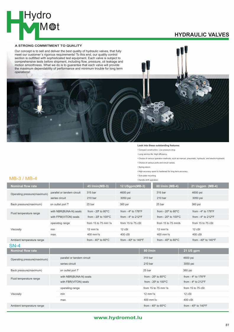
A STRONG COMMITMENT TO QUALITY
Our concept is to sell and deliver the best quality of hydraulic valves, that fullymeet our customer´s rigorous requirements! To this end, our quality controlsection is outfitted with sophisticated test equipment. Each valve is subject tocomprehensive tests before shipment, including flow, pressure, oil leakage andmotion smoothness. What we do is to guarantee that each valve will providethe maximum dependability of performance and minimum trouble for long termoperations!
MB-3 / MB-4
Nominal flow rate 45 l/min(MB-3) 12 USgpm(MB-3) 80 l/min (MB-4) 21 Usgpm (MB-4)
Operating pressure(maximum)parallel or tandem circuit 315 bar 4600 psi 315 bar 4600 psi
series circuit 210 bar 3050 psi 210 bar 3050 psi
Back pressure(maximum) on outlet port T 25 bar 360 psi 25 bar 360 psi
Fluid temperature rangewith NBR(BUNA-N) seals from - 20º to 80ºC from - 4º to 176ºF from - 20º to 80ºC from - 4º to 176ºF
with FPM(VITON) seals from - 20º to 100ºC from - 4º to 212ºF from - 20º to 100ºC from - 4º to 212ºF
2 2operating range from 15 to 75 mm /s from 15 to 75 cSt from 15 to 75 mm/s from 15 to 75 cSt
Viscosity min 12 mm 2/s 12 cSt 12 mm2/s 12 cSt
max. 400 mm2/s 400 cSt 400 mm2/s 400 cSt
Ambient temperature range from - 40º to 60ºC from - 40º to 140ºF from - 40º to 60ºC from - 40º to 140ºF
SN-4Nominal flow rate 80 l/min 21 US gpm
Operating pressure(maximum)parallel or tandem circuit 315 bar 4600 psi
series circuit 210 bar 3050 psi
Back pressure(maximum) on outlet port T 25 bar 360 psi
Fluid temperature rangewith NBR(BUNA-N) seals from - 20º to 80ºC from - 4º to 176ºF
with FBR(VITON) seals from - 20º to 100ºC from - 4º to 212ºF
2operating range from 15 to 75 mm /s from 15 to 75 cSt
Viscosity min 12 mm 2/s 12 cSt
max. 400 mm2/s 400 cSt
Ambient temperature range from - 40º to 60ºC from - 40º to 140ºF
Look into these outstanding features:
• Compact construction. Low pressure drop.
• Long service life. High efficiency.
• Choice of various operation methods, such as manual, pneumatic, hydraulic, and electro-hydraulic.
• Choice of various ports and circuit valves.
• Spring return.
• High accuracy spool is hardened for long term accuracy.
• Sub-plate mounting.
• Handle shift operation.
81
www.hydromot.lu
HydroM t
HydroMot S.a.r.l. 204 rte de Luxembourg L-7241 Bereldange Tel.: +352 263375 - 830 Fax: +352 263375 -839
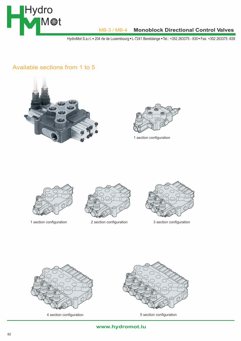
MB-3 / MB-4 Monoblock Directional Control Valves
Available sections from 1 to 5
3 section configuration
5 section configuration4 section configuration
2 section configuration1 section configuration
1 section configuration
82
HydroM t
www.hydromot.lu
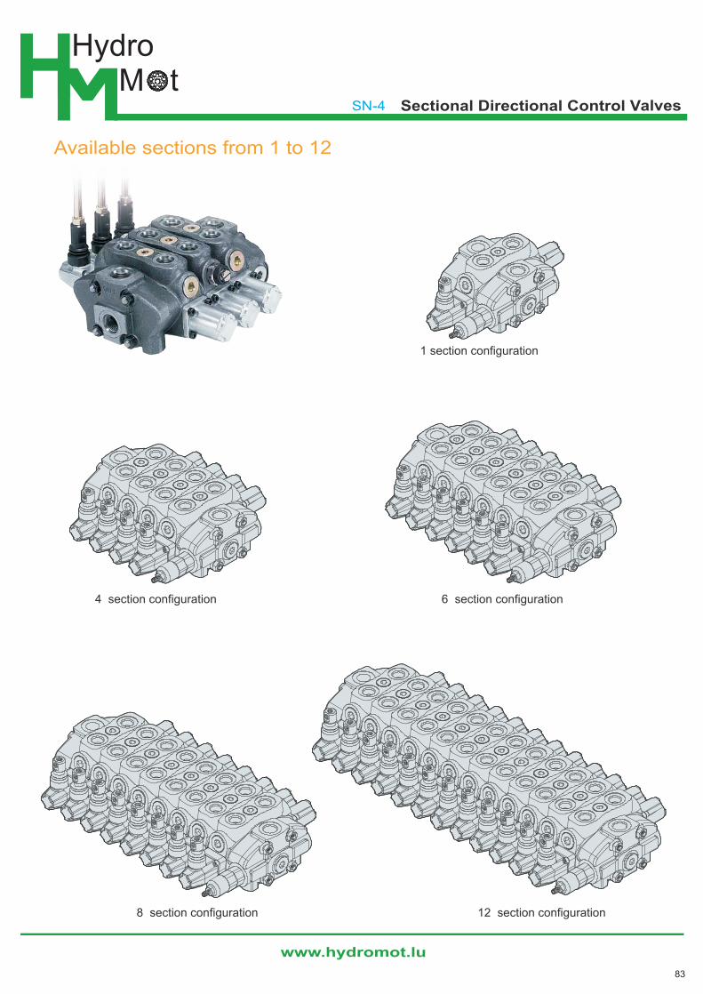
SN-4 Sectional Directional Control Valves
Available sections from 1 to 12
1 section configuration
4 section configuration
8 section configuration 12 section configuration
6 section configuration
83
HydroM t
www.hydromot.lu
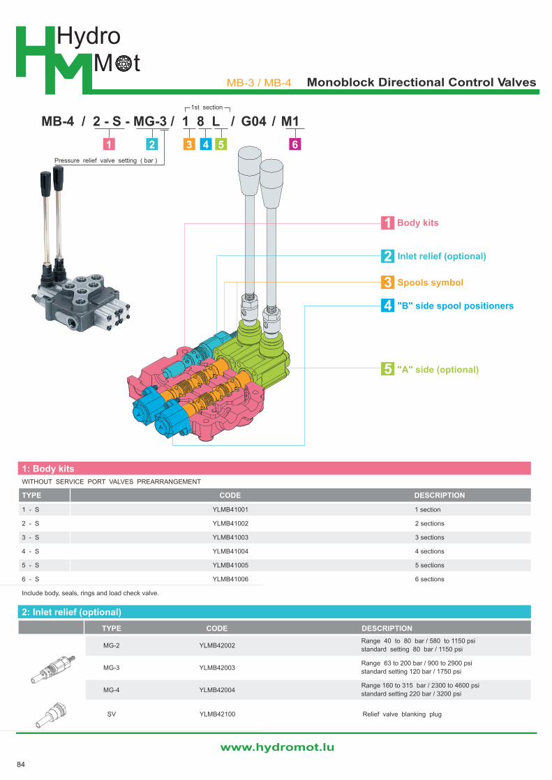
MB-3 / MB-4 Monoblock Directional Control Valves
1: Body kits
WITHOUT SERVICE PORT VALVES PREARRANGEMENT
TYPE CODE DESCRIPTION
1 - S YLMB41001 1 section
2 - S YLMB41002 2 sections
3 - S YLMB41003 3 sections
4 - S YLMB41004 4 sections
5 - S YLMB41005 5 sections
6 - S YLMB41006 6 sections
Include body, seals, rings and load check valve.
2: Inlet relief (optional)
TYPE CODE DESCRIPTION
MG-2 YLMB42002Range 40 to 80 bar / 580 to 1150 psi
standard setting 80 bar / 1150 psi
MG-3 YLMB42003Range 63 to 200 bar / 900 to 2900 psi
standard setting 120 bar / 1750 psi
MG-4 YLMB42004Range 160 to 315 bar / 2300 to 4600 psi
standard setting 220 bar / 3200 psi
SV YLMB42100 Relief valve blanking plug
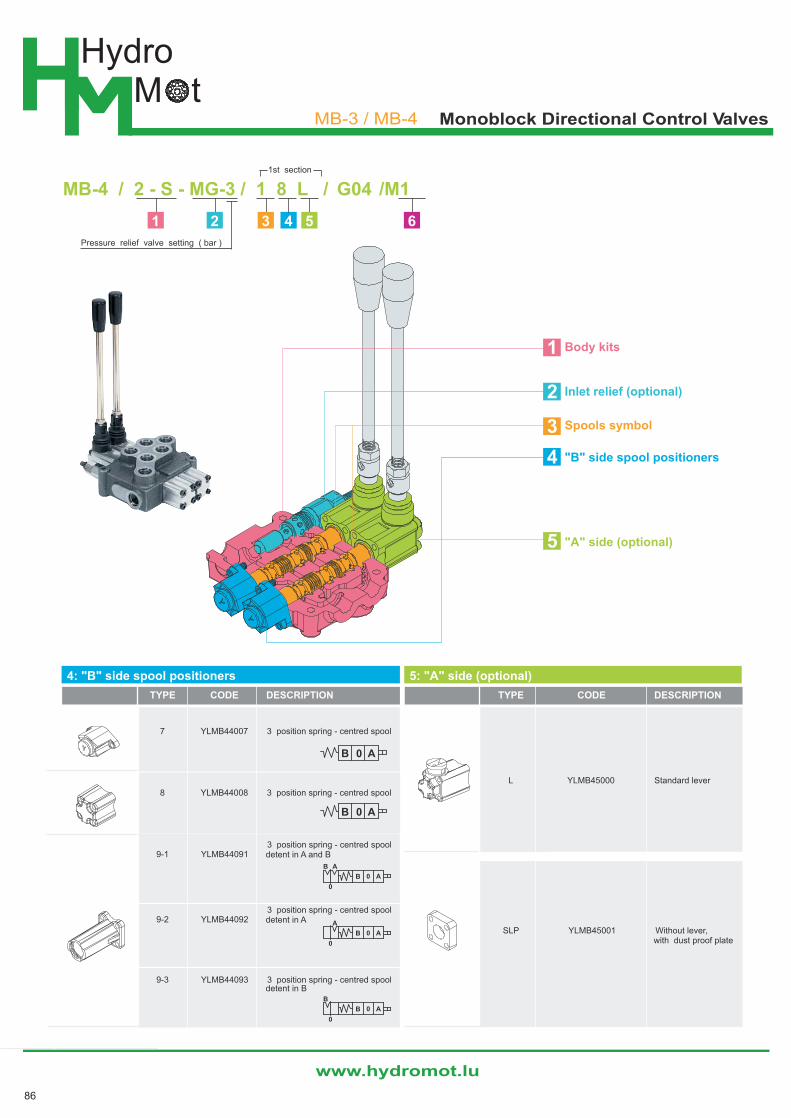
MB-4 / 2 - S - MG-3 / 1 8 L / G04 / M1
Pressure relief valve setting ( bar )
1st section
2
3
1
4
5
1 2 3 4 5 6
Body kits
Inlet relief (optional)
Spools symbol
"B" side spool positioners
"A" side (optional)
84
HydroM t
www.hydromot.lu
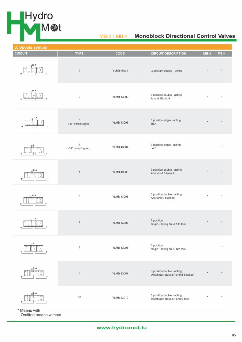
3: Spools symbol
CIRCUIT TYPE CODE CIRCUIT DESCRIPTION MB-3 MB-4
1 YLMB43001 3 position double - acting * *
2 YLMB 430023 position double - acting
* *A and Bto tank
3YLMB 43003
3 position single - acting* *
("B" port plugged) on A
4YLMB 43004
3 position single - acting*
("A" port plugged) on B
5 YLMB 430053 position double - acting
* *A blocked B to tank
6 YLMB 430063 position double - acting
* *A to tank B blocked
7 YLMB 430073 position
* *single - acting on A A to tank
8 YLMB 430083 position
*single - acting on B Bto tank
9 YLMB 430093 position double - acting
* *switch port closed A and B blocked
10 YLMB 430103 position double - acting
* *switch port closed A and B tank
* Means with Omitted means without
P T
B AC
C
P T
B A
C
P T
B A
P T
B AC
P T
CA
P T
CB
P T
BC
P T
AC
B
P
CB
T
A
TP
CA
MB-3 / MB-4 Monoblock Directional Control Valves
85
HydroM t
www.hydromot.lu
MB-3 / MB-4 Monoblock Directional Control Valves
4: "B" side spool positioners
TYPE CODE DESCRIPTION
7 YLMB44007 3 position spring - centred spool
8 YLMB44008 3 position spring - centred spool
9-1 YLMB440913 position spring - centred spooldetent in A and B
9-2 YLMB440923 position spring - centred spooldetent in A
9-3 YLMB44093 3 position spring - centred spooldetent in B
B 0 A
B
0
0
B A
0
0
B
A
A
0
0
B A
AB
AB 0
5: "A" side (optional)
TYPE CODE DESCRIPTION
L YLMB45000 Standard lever
SLP YLMB45001 Without lever,with dust proof plate
2
3
1
4
5
Body kits
Inlet relief (optional)
Spools symbol
"B" side spool positioners
"A" side (optional)
MB-4 / 2 - S - MG-3 / 1 8 L / G04 /M1
Pressure relief valve setting ( bar )
1st section
1 2 3 4 5 6
86
HydroM t
www.hydromot.lu
PP
T T
C C
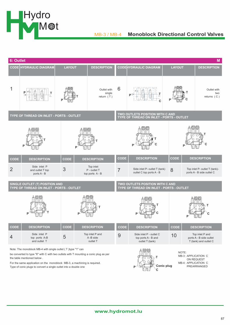
CODE HYDRAULIC DIAGRAM LAYOUT DESCRIPTION
1 Outlet with
single
return ( T )
TYPE OF THREAD ON INLET - PORTS - OUTLET
CODE DESCRIPTION CODE DESCRIPTION
Side inlet P
2 3Top inlet
and outlet T top P - outlet T
ports A - B top ports A - B
P
P
TT
P P
T T
CODEHYDRAULIC DIAGRAM LAYOUT DESCRIPTION
6 Outlet with
two
returns ( C )
TWO OUTLETS POSITION WITH C AND TYPE OF THREAD ON INLET - PORTS - OUTLET
CODE DESCRIPTION CODE DESCRIPTION
Side inlet P- outlet T (tank) Top inlet P- outlet T (tank)-7 8outlet C top ports A - B ports A - B side outlet C
P T
C P
T
C
PP
T
T
CC
SINGLE OUTLET (T) POSITION AND TYPE OF THREAD ON INLET - PORTS - OUTLET
CODE DESCRIPTION CODE DESCRIPTION
Side inlet P Top inlet P and
4 5top ports A-B A -B side
and outlet T outlet T
Note: The monoblock MB-4 with single outlet ( T )type "1" can
be converted to type "6" with C with two outlets with T mounting a conic plug as per
the table mentioned below .
For the same application on the monoblock MB-3, a machining is required.
Type of conic plugs to convert a single outlet into a double one
P PT
T
TWO OUTLETS POSITION WITH C ANDTYPE OF THREAD ON INLET - PORTS - OUTLET
CODE DESCRIPTION CODE DESCRIPTION
Side inlet P - outlet C Top inlet P and 9 10top ports A - B and ports A - B side outlet
outlet T (tank) T (tank) and outlet C
NOTE:
MB-3 : APPLICATION C
ON REQUEST
MB-4 : APPLICATION C
PREARRANGEDP
T
C
Conic plug
6: Outlet M
MB-3 / MB-4 Monoblock Directional Control Valves
87
HydroM t
www.hydromot.lu
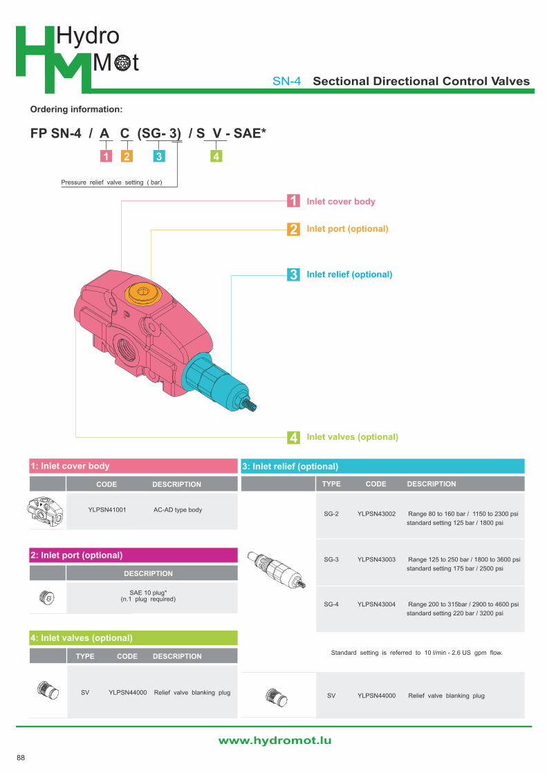
FP SN-4 / A C (SG- 3) / S V - SAE*
Pressure relief valve setting ( bar)
1 2 3 4
1: Inlet cover body
CODE DESCRIPTION
YLPSN41001 AC-AD type body
2: Inlet port (optional)
DESCRIPTION
SAE 10 plug*(n.1 plug required)
3: Inlet relief (optional)
TYPE CODE DESCRIPTION
SG-2 YLPSN43002 Range 80 to 160 bar / 1150 to 2300 psi
standard setting 125 bar / 1800 psi
SG-3 YLPSN43003 Range 125 to 250 bar / 1800 to 3600 psi
standard setting 175 bar / 2500 psi
SG-4 YLPSN43004 Range 200 to 315bar / 2900 to 4600 psi
standard setting 220 bar / 3200 psi
Standard setting is referred to 10 l/min - 2.6 US gpm flow.
SV YLPSN44000 Relief valve blanking plug
4: Inlet valves (optional)
TYPE CODE DESCRIPTION
SV YLPSN44000 Relief valve blanking plug
3
2
1
4
Ordering information:
Inlet cover body
Inlet port (optional)
Inlet relief (optional)
Inlet valves (optional)
SN-4 Sectional Directional Control Valves
88

HydroM t
www.hydromot.lu
SN-4 Sectional Directional Control Valves
5
4
3
2
1
Outlet section parts
PART CODE Q'TY DESCRIPTION
YLTSN45001 1 Outlet section body *
- 1 SEA 10 plug *
- 3 18.77x1.78 NBR 70 SH O-Ring seal
- 1 25.12x1.78 NBR 70 SH O-Ring seal
Circuit option
PART CODE Q'TY DESCRIPTION
M18x1.5 plug
YLTSN45002 1 For power beyond (RE) and closed
center (RK) option
NOTE (*) - Items are referred to UN-UNF thread
Outlet section
Description example:
FT SN-4 / R C - S A E*
1
2
3
4
89

HydroM t
www.hydromot.lu
SN-4 Sectional Directional Control Valves
1: Working section kits
TYPE CODE DESCRIPTION
P YLWSN41001 Parallel
Include body , seals , rings and load check valve
2:Spool symbol
CIRCUIT TYPE CODE CIRCUIT DESCRIPTION
1 YLWSN42001 Double acting,3 positions,with A and B
closed in neutral position
1S YLWSN42010 Double acting,3 positions,with A and B
closed in neutral position,for series
6 YLWSN42006 Double acting,3 positions,with A
open to tank in neutral position
5 YLWSN42005 Double acting,3 positions,with B
open to tank in neutral position
2 YLWSN42002 Double acting,3 positions,with A and B
open to tank in neutral position
3 YLWSN42003 Single acting on A,3 positions, B plugged
("B" port plugged) requires SAE 8 plug (see port B)
4 YLWSN42004 Single acting on B,3 positions, A plugged
("A" port plugged) requires SAE 8 plug (see port A)
P T
A B1 0 2
0
P
A1
T
B2
P T
0A
1B
2
0
P
A1
T
B2
0
P
A1
T
B2
0
P
A1
T
2
0
P
1
T
B2
2
5
3
1
4
Y
Inlet section :
Working section kits
Spool symbol
"A"side Spool positioners
"B" side (optional)
Port relief (optional)
Optional hand / levers
EW SN-4 / 1 - S / 1 8 L / P1(G 3 ) - SAE*
port relief valve setting in bar
1 mounted on A port.
2 mounted on B port.
3 mounted on A and B port.
1 2 3 4 5
1st section
90

HydroM t
www.hydromot.lu
SN-4 Sectional Directional Control Valves
4: "B" side (optional)
TYPE CODE DESCRIPTION
L YLWSN44000 Standard lever
SLP YLWSN44001 Without lever,with
dust proof plate
3: "A"side Spool positioners
TYPE CODE DESCRIPTION
8 YLWSN3008 With spring return
in neutral position
Y: Optional hand / levers
TYPE CODE DESCRIPTION
YL01/M10x200 170012020 For L lever boxL=200 mm/7.87 in
5: Port relief (optional)
TYPE CODE DESCRIPTION
P (G3-100) YLWSN45003 Range 100 to 250 bar / form 1450 to 3600 psi
standard setting 100bar / 1450 psi
P (G4-200) YLWSN45004 Range 200 to 315 bar / form 2900 to 4600 psi
standard setting 200 bar / 2900 psi
U (G2-63) YLWSN45012 Range 63 to 125 bar / form 900 to 1800 psi
standard setting 63 bar / 900 psi
U (G3-100) YLWSN45013 Range 100 to 250 bar / form 1450 to 3600 psi
standard setting 100 bar / 1450 psi
U (G4-200) YLWSN45014 Range 200 to 315 bar / form 2900 to 4600 psi
standard setting 200 bar / 2900 psi
Standard setting is referred to 10 l/min -2.6 us gpm flow.
C YLWSN45100 Anti - cavitation
P3T YLWSN45200 A and B ports valve blanking plugs
Anti-shock valve
Anti-shock valve andanti - cavitation valve
91
HydroM t
www.hydromot.lu
MB-3 / MB-4 Monoblock Directional Control Valves
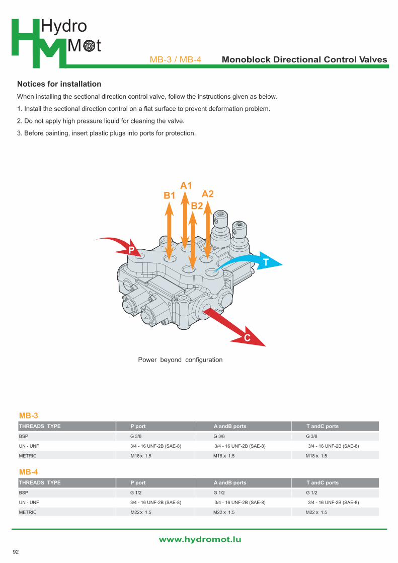
Notices for installation
When installing the sectional direction control valve, follow the instructions given as below.
1. Install the sectional direction control on a flat surface to prevent deformation problem.
2. Do not apply high pressure liquid for cleaning the valve.
3. Before painting, insert plastic plugs into ports for protection.
MB-3
THREADS TYPE P port A andB ports T andC ports
BSP G 3/8 G 3/8 G 3/8
UN - UNF 3/4 - 16 UNF-2B (SAE-8) 3/4 - 16 UNF-2B (SAE-8) 3/4 - 16 UNF-2B (SAE-8)
METRIC M18 x 1.5 M18 x 1.5 M18 x 1.5
MB-4
THREADS TYPE P port A andB ports T andC ports
BSP G 1/2 G 1/2 G 1/2
UN - UNF 3/4 - 16 UNF-2B (SAE-8) 3/4 - 16 UNF-2B (SAE-8) 3/4 - 16 UNF-2B (SAE-8)
METRIC M22 x 1.5 M22 x 1.5 M22 x 1.5
A1B1 A2
B2
C
PT
Power beyond configuration
92
HydroM t
www.hydromot.lu
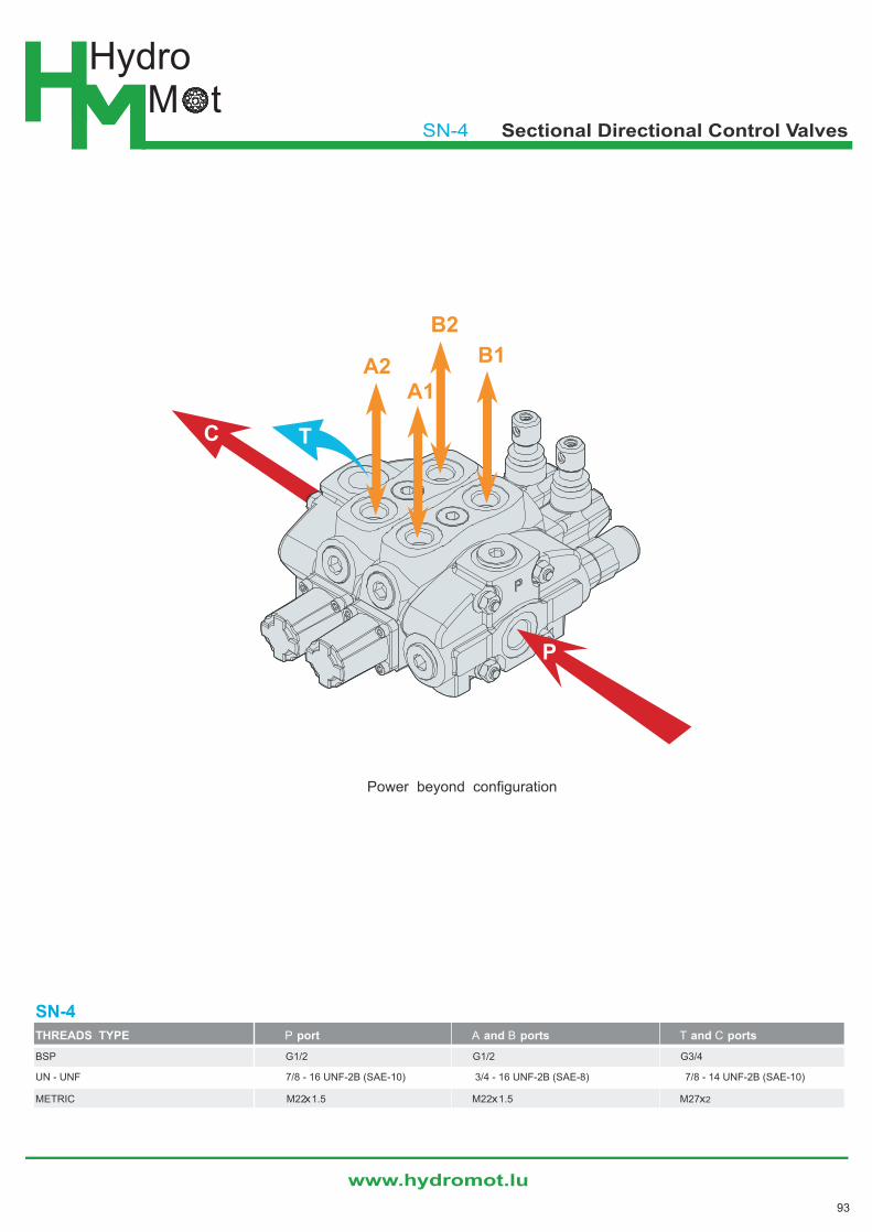
SN-4 Sectional Directional Control Valves
Power beyond configuration
A1
B1A2
B2
P
C T
SN-4THREADS TYPE P port A and B ports T and C ports
BSP G1/2 G1/2 G3/4
UN - UNF 7/8 - 16 UNF-2B (SAE-10) 3/4 - 16 UNF-2B (SAE-8) 7/8 - 14 UNF-2B (SAE-10)
METRIC M22x1.5 M22x1.5 M27x2
93

HydroM t
www.hydromot.lu
MB-3 / MB-4 Monoblock Directional Control Valves
Standard threads
PORTS BSP UN-UNF METRIC
Inlet P G1/2 3/4-16 UNF-2B (SAE 8) M18x1.5
A and B ports G1/2 3/4-16 UNF-2B (SAE 8) M18x1.5
Outlet T and power beyond C G1/2 3/4-16 UNF-2B (SAE 8) M18x1.5
TYPEX Y WEIGHT
mm in mm in kg lb
MB-4/1-S 101.5 4 77.5 3.05 4.0 6.4
MB-4/2-S 136.5 5.37 112.5 4.43 5.1 9.48
MB-4/3-S 171.5 6.75 147.5 5.81 6.6 12.13
TYPEX Y WEIGHT
mm in mm in kg lb
MB-4/4-S 206.5 8.13 182.5 7.19 8.2 14.77
MB-4/5-S 241.5 9.51 217.5 8.56 9.7 17.42
MB-4/6-S 276.5 10.89 252.5 9.94 11.2 20.06
92
1041
33
47
.5
16 35 25
34
33
15
ø9
67
70
11
58
10
35
3.5
21
5
1934
53
14º
16º
16º
Floating extra stroke83.5
42.5(3.62)
(2.64)
(1.61)
(0.39)
((2
.76
)
(1.3
)(1
.87
)
(0.63) (1.38) (0.98)
(1.69)(0
.43
)
(1.3
)(1
.34
)
(3.29)
(1.67)
(2.2
8)
(4.0
6)
(2.1
1)
(8.4
6)
(1.34) (0.75)
(2.09)
C
A
PB
T
88.5
16º
58
20
5
10
43
3
40
60
21.538.5
Floating extra stroke
(1.52) (0.85)
(2.36)
(1.3
)(4
.09
)(2
.28
)
(1.5
7)
(8.0
7)
(3.48)
X
Y
172718 35(0.71) (1.28)
32.5(1.06)(1.38) (0.67)
(0.8
9)
22
.5
ø6.5
(1.9
1)
48
.5
24
(0.9
5)
33
(1.3
)
(0.26)
192532.525 35(0.98) (1.28) (0.98)(1.38) (0.75)
(1.2
8)
(1.3
)
79
32
.5
C
33
(0.4
9)
(0.4
9)
(3.1
1)
7(0.28)
A2A1
B1
P
B2T
12.5
16º
12.5
16º
Standard threads
PORTS BSP UN-UNF METRIC
Inlet P G3/8 3/4-16 UNF-2B (SAE 8) M18 x 1.5
A and B ports G3/8 3/4-16 UNF-2B (SAE 8) M18 x 1.5
Outlet T and power beyond C G3/8 3/4-16 UNF-2B (SAE 8) M18 x 1.5
MB-3
MB-4
94
HydroM t
www.hydromot.lu
SN-4 Sectional Directional Control Valves
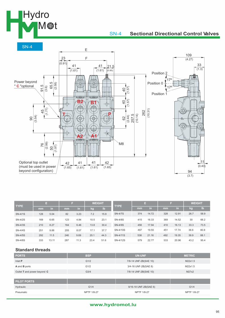
SN-4
TYPEE F WEIGHT
mm in mm in kg lb
SN-4/1S 128 5.04 82 3.23 7.2 15.9
SN-4/2S 169 6.65 123 4.84 10.5 23.1
SN-4/3S 210 8.27 164 6.46 13.8 30.4
SN-4/4S 251 9.88 205 8.07 17.1 37.7
SN-4/5S 292 11.5 246 9.69 20.1 44.3
SN-4/6S 333 13.11 287 11.3 23.4 51.6
TYPEE F WEIGHT
mm in mm in kg lb
SN-4/7S 374 14.72 328 12.91 26.7 58.9
SN-4/8S 415 16.33 369 14.52 30 66.2
SN-4/9S 456 17.94 410 16.13 33.3 73.5
SN-4/10S 497 19.55 451 17.74 36.6 80.8
SN-4/11S 538 21.16 492 19.35 39.9 88.1
SN-4/12S 579 22.77 533 20.96 43.2 95.4
Standard threads
PORTS BSP UN-UNF METRIC
Inlet P G1/2 7/8-14 UNF-2B(SAE 10) M22x1.5
A and B ports G1/2 3/4-16 UNF-2B(SAE 8) M22x1.5
Outlet T and power beyond C G3/4 7/8-14 UNF-2B(SAE 10) M27x2
PILOT PORTS
Hydraulic G1/4 9/16-18 UNF-2B(SAE 6) G1/4
Pneumatic NPTF 1/8-27 NPTF 1/8-27 NPTF 1/8-27
17º
17º
Position 2
Position 1
Position 0
A1
B1
A2
B2
PT
65
.55
0
45
90
F
E
23
41 41
42 41 41 42
21.5
40
40
62
M8
76
91
.5
26
2
25
7.5
(3.6
)
(3.5
4)
(2.9
9)
(2.5
8)
(1.7
7)
(1.9
7)
(0.91)
(1.61) (1.61) (0.85)
(1.65) (1.61) (1.61) (1.65)
(2.4
4)
(1.5
7)
(1.5
7)
(10
.14
)
(10
.31
)
109
33
94
11
(4.27)
(1.3)
(0.43)
(3.7)
Power beyond" "optionalC
Optional top outlet(must be used in powerbeyond configuration)
95