hydraulics of roman aqueducts: steep chutes,...
TRANSCRIPT

American Journal of Archaeology
104 (2000) 47–7247
Hydraulics of Roman Aqueducts: Steep Chutes, Cascades, and Dropshafts
H. CHANSON
Abstract
This paper examines the archaeological evidencefor steep chutes, cascades, and dropshafts in Romanaqueducts. It also presents comparative data on steep-descent water flow in aqueducts based on physicalmodel tests. It is suggested that the Romans wereaware of the hydraulic problems posed by supercriti-cal water flows and that the technological solutionsthey imposed were rudimentary but sound: for exam-ple, they understood the need for energy dissipationdevices such as the stilling basin and the dropshaft.*
The Roman aqueduct remains one of the best ex-amples of hydraulic expertise in antiquity. Manyaqueducts were used, repaired, and maintained forcenturies, and some, such as the aqueduct of Carthage(Tunisia), are still partly in use today.
1
Most aque-ducts consisted of long, flat sections interspersed byshorter steep drops. Despite arguments suggestingthat Roman aqueducts maintained a fluvial flow re-gime,
2
the present study suggests that these steepdrops produced supercritical flows requiring a tech-nical response to ensure normal water flow; it alsoargues that the Romans employed three methods toaddress this problem: chutes followed by stillingbasins, stepped channels, and dropshafts.
steep chutes and stepped cascades: hydraulic considerations
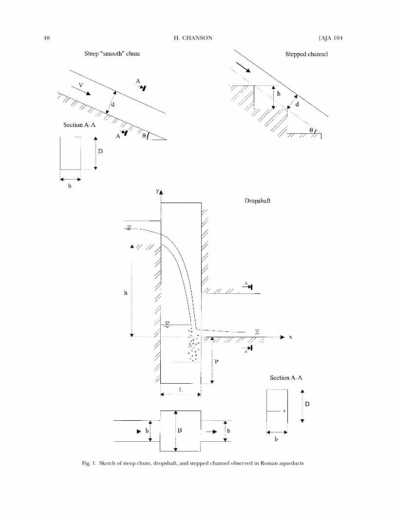
A chute is characterized by a steep bed slope asso-ciated with torrential flow (figs. 1–3). This chute flow
* I wish to acknowledge the following people (in alpha-betical order) for their help and assistance: Professor C.Apelt, The University of Queensland, Australia; Mr. G. BergeJussy, France; Dr. D. Blackman, Monash University, Australia;Ms. Chou Y.H., Brisbane, Australia; Dr. M.R. Gourlay, TheUniversity of Queensland, Australia; Dr. A.T. Hodge, Carle-ton University, Canada; Mr. G. Illidge, The University ofQueensland, Australia; Mr. C. Lefebvre, Châtel-St.-Germain,France; Mr. P. Leveau, Université d’Aix-en-Provence, France;Mr. D. Murphy for information on Andriake cascade; Mr.J.L. Paillet, I.R.A.A., Aix-en-Provence, France; Professor N.Rajaratnam, University of Alberta, Canada; Dr. Y. Yasuda, Ni-hon University, Tokyo. In addition, I thank Dr. R.B. Hitch-ner, Editor-in-Chief of
AJA
, and Dr. S.R. Holman, former As-sociate Editor, for their helpful comments.
1
Clamagirand et al. 1990, 423–31.
2
That is, a tranquil flow regime such as the flow Froudenumber is less than unity (e.g., Chanson 1999).
3
The Carthage aqueduct has a moderate slope (0.7%) up-
may be either smooth (fig. 2) or stepped (fig. 3). Ro-man designers used both designs as well as singledrops along aqueducts (tables 1 and 2). There is ar-chaeological evidence of smooth chutes along theBrévenne, Cherchell, Corinth, and Gorze aqueducts,and on the Anio Vetus, Claudia, Marcia, and AnioNovus aqueducts at Rome (table 1).
3
Although thereis less information on stepped channels, those at An-driake and Beaulieu are well documented. Damspillways also employed smooth and stepped-chutedesigns. The oldest known stepped spillway wasbuilt around 1300 B.C. in Greece,
4
and the famousMarib dam (Yemen) was equipped with an unlinedrock chute on the left bank to spill flood waters.Roman engineers also built several significant spill-way systems.
5
The appendix provides some basic hydraulic cal-culations that I have applied to well-documentedsteep chutes. Tables 1 and 2 (column 4) summa-rize the results of these calculations. They wereperformed for “accepted” maximum flow rates (ta-ble 3) and demonstrate that high-velocity flows(velocities in excess of 8 m/s) occurred along sev-eral Roman aqueducts. The hydraulics of fluvialand torrential flows is distinguished by their fun-damentally different behaviors. Torrential (super-critical) flows produce a much greater kinetic en-ergy than fluvial flows. This value is normallyexpressed in terms of a “Froude number”;
6
that is,
stream of the Oudna arcades, but the channel is technicallytermed “steep” because the flow was considered torrential.
4
The overflow stepped weir in Akarnania, Greece, builtaround 1300 B.C., is an earthfill embankment, 10.5 m high,with a 25 m-long crest. The downstream slope is stepped (14steps) with masonry rubbles set in mortar. The weir was usedfor several centuries. It is still standing, and flash floods spillover the stepped chute. See Chanson 1997; Knauss 1995.
5
Roman dams equipped with a chute spillway system in-cluded: Cornalvo (Spain, second century A.D.), Al Khums(Libya, third century A.D.). Examples of drop spillway in-cluded Harbaka (Syria, third century A.D.). Examples ofstepped spillway include the Kasserine dam (Tunisia),Oued Guergour dam (Tunisia, first century A.D.), QasrKhubbaz (Syria, second century A.D.), and Tareglat dam(Libya, third century A.D.). See Chanson 1995a, 23–37.
6
The Froude number for a rectangular channel is de-fined as the ratio of the velocity to the square root of thegravity acceleration times the flow depth: i.e., .Fr V/ gd=
48 H. CHANSON [AJA 104
Fig. 1. Sketch of steep chute, dropshaft, and stepped channel observed in Roman aqueducts
2000] HYDRAULICS OF ROMAN AQUEDUCTS 49
the calculation of the properties of fluvial (lowerenergy) flows will produce a Froude number lessthan 1, while the properties of torrential flows pro-duce a Froude number greater than 1. Supercriticaltorrential flow was consistently present along theentire channel of each investigated chute (table 1,column 4). Downstream of the chute, the transitionto a slower flow motion took place as a hydraulic“jump,” characterized by strong energy dissipation(see appendix).
In modern engineering, hydraulic designers seekto avoid three types of hydraulic jumps: strong, oscil-lating, and undular jumps (fig. 4). Bed erosion and
“scouring” is more likely whenever there is a stronghydraulic jump, abruptly increasing the scour poten-tial of the water at any point. It is believed that Ro-man aqueduct mortar and concrete could never sus-tain the “uplift forces” that occur in the water justbeyond these strong jumps.
7
Oscillating jumpspresent the risk that the position of the roller wouldbe unsteady and fluctuate over great lengths. Fur-ther, the oscillating jump would be characterized bythe unsteady propagation of the surge waves, highlyundesirable in a narrow channel.
8
The third undesir-able change in water flow pattern, the undular hy-draulic jump, produces steady, stationary free-surface
7
This comment is based upon my experience (associ-ated with site inspections of several aqueducts) in severalhydraulic studies related to concrete deterioration. I havediscussed the issue of concrete resistance with world-knownconcrete experts and historians, who suggested similar re-sults in Roman concrete and 19th-century concrete.
8
“This type [of jump] has a pulsating action. . . . [It] isone of the most difficult [types of jump] to handle” (Brad-
ley and Peterka 1957a, 1401–22). Bradley and Peterka’swork also highlighted specific problems in confined chan-nels: “In narrow structures, such as canals [and aque-ducts], waves may persist to some degree for miles. . . .Structures in this range of Froude numbers are the oneswhich have been found to require the most maintenance”(Bradley and Peterka 1957b, 1404–20).
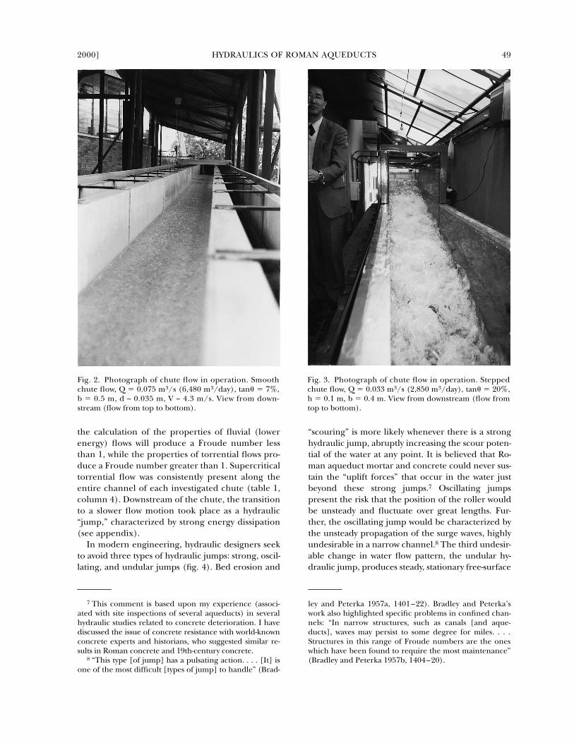
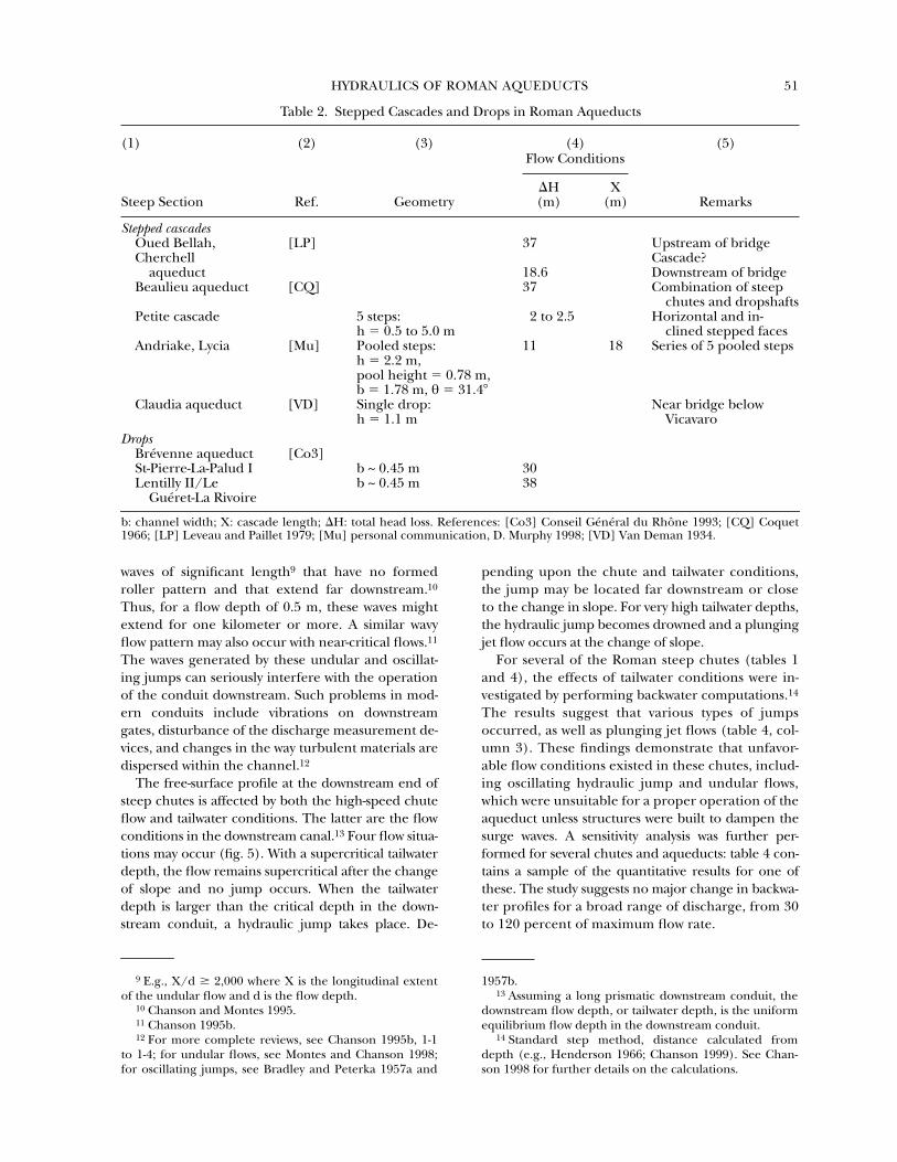
Fig. 2. Photograph of chute flow in operation. Smoothchute flow, Q � 0.075 m3/s (6,480 m3/day), tan� � 7%,b � 0.5 m, d ~ 0.035 m, V ~ 4.3 m/s. View from down-stream (flow from top to bottom).
Fig. 3. Photograph of chute flow in operation. Steppedchute flow, Q � 0.033 m3/s (2,850 m3/day), tan� � 20%,h � 0.1 m, b � 0.4 m. View from downstream (flow fromtop to bottom).

50 H. CHANSON [AJA 104
Table 1. Steep Smooth Chutes in Roman Aqueducts
(1) (2) (3) (4) (5)Flow Conditions
Steep Section Ref. Geometry
�
H(m)
d
o
(m)
V
o
(m/s)
X (m) Remarks
Brévenne aqueduct
[Co3]Courzieu II/
La Verrièreb ~ 0.55 m,
θ
�
12.4
�
, mortar44 0.05 4.24 Chute C1; 2.4 km upstream
of the Basin of SotizonChevinay/Plainet b ~ 0.76 m,
θ
�
24.2
�
, paved stone87 0.052 4.45 Chute C2
Lentilly II/Les Molières-Montcher
b
�
45 m, D
�
0.8 m,
θ
�
4.7
�
, mortar33 0.0795 3.25 Chute C5
Limonest/La Bruyère
b ~ 0.53 m, mortar 8 Chute C6
Cherchell aqueduct
[LP]Chabet Ilelouine b
�
1.3 m,
θ
�
38.0
�
12.3 0.045 8 4 series of steep chutes followed by circular dropshaft
Corinth aqueduct
[Lo]Alepotrypes b ~ 1.1 m,
θ
�
1.72
�
, mortar0.29 3.62 Upstream of a large stilling
basin (40
�
11 m
2
)
Gorze aqueduct
[Le]Bridge over Moselle Two parallel canals,
each: b
�
0.85 m,
θ
�
0.022
�
, mortar
4.3 1,100 Upstream calming basin (Ars-sur-Moselle) and downstream stilling basin ( Jouy-aux-Arches)
0.111 0.92 2 canals in operation0.177 1.15 1 canal in operation
Anio Vetus aqueduct
Tivoli, Hadrian’s Villa [VD] b
�
0.8 m, D
�
1.25 m,
θ
�
11.6
�
, rocks and bricks
0.7 0.332 8.3 Short section [VD, p. 40; AS, pp. 63–64]
Bridge at Mola di San Gregoria
[AS] b ~ 1.05 m, D ~ 2.37 m,
θ
�
9.3
�
4.09 0.236 8.9 [AS, pp. 68–70]
Claudia aqueduct
below D. Cosimato cliff
[VD] b
�
1.15 m, D
�
0.9 m,
θ
�
26.6
�
, coarse concrete with rough reticulate
5.48 0.18 10.7 Upstream of bridge below Vicavaro [VD, p. 196; AS, p. 196]
Marcia aqueduct
Casale Acqua Raminga, Gericomio
[Bl] b
�
1.15 m,
θ
�
8.9
�
, rough concrete
3.98 0.329 5.75 25.4 Upstream section[AS, p. 115; VD, p. 92]
b
�
1.15 m,
θ
�
6.13
�
, roughconcrete
31.9 0.374 5.05 204 Downstream section
Anio Novus
near Torrente Fiumicino
[Bl] b
�
1.25 m,
θ
�
3.48
�
, brick work6.8 0.315 5.58 [AS, p. 261; VD, p. 280]
Ponte dell’Inferno to Ponte Scalino
[AS] b
�
1.06 m,
θ
�
0.604
�
26.37 0.765 2.71 Unlined rock tunnel; cascades or steps? [AS, p. 287]
Ponte Scalino to Ponte Amato
[AS] b ~ 1 m,
θ
�
0.94
�
0.686 3.21 Unlined rock tunnel; cascades or steps? [AS, p. 287]
Fienile [AS] b ~ 1 m,
θ
�
0.76
�
0.747 2.95 Unlined rock tunnel; cascades or steps? [AS, p. 287]
Carthage aqueduct
[Ra]upstream of Oudna
arcades
b
�
0.865 m,
θ
�
0.40
�
, mortar
0.157
1.47
Immediately upstream of Oued Miliane plain
arcades
d
o
: normal flow depth; V
o
: normal flow velocity; X: chute length;
�
H: total head loss. References: [AS] Ashby 1935; [Bl] Black-man 1978; [Co3] Conseil Général du Rhône 1993; [CQ] Coquet 1966; [Le] Lefebvre 1996; [LP] Leveau and Paillet 1976;[Lo] Lolos 1997; [Ra] Rakob 1974; [VD] Van Deman 1934.
2000] HYDRAULICS OF ROMAN AQUEDUCTS 51
waves of significant length
9
that have no formedroller pattern and that extend far downstream.
10
Thus, for a flow depth of 0.5 m, these waves mightextend for one kilometer or more. A similar wavyflow pattern may also occur with near-critical flows.
11
The waves generated by these undular and oscillat-ing jumps can seriously interfere with the operationof the conduit downstream. Such problems in mod-ern conduits include vibrations on downstreamgates, disturbance of the discharge measurement de-vices, and changes in the way turbulent materials aredispersed within the channel.12
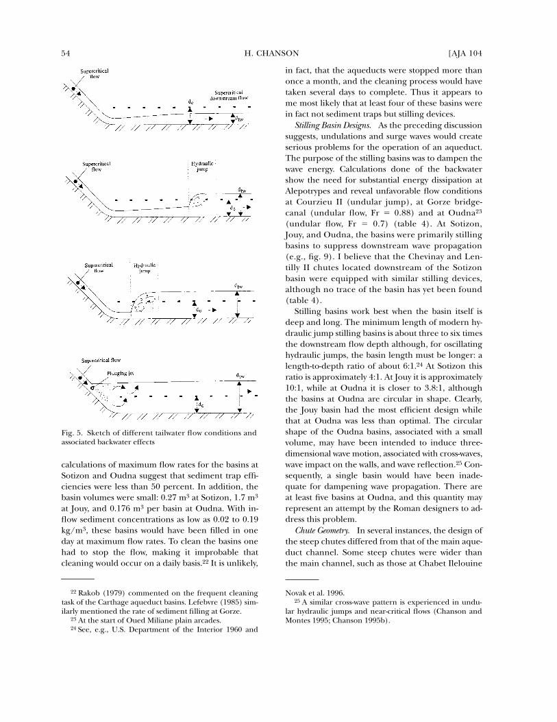
The free-surface profile at the downstream end ofsteep chutes is affected by both the high-speed chuteflow and tailwater conditions. The latter are the flowconditions in the downstream canal.13 Four flow situa-tions may occur (fig. 5). With a supercritical tailwaterdepth, the flow remains supercritical after the changeof slope and no jump occurs. When the tailwaterdepth is larger than the critical depth in the down-stream conduit, a hydraulic jump takes place. De-
pending upon the chute and tailwater conditions,the jump may be located far downstream or closeto the change in slope. For very high tailwater depths,the hydraulic jump becomes drowned and a plungingjet flow occurs at the change of slope.
For several of the Roman steep chutes (tables 1and 4), the effects of tailwater conditions were in-vestigated by performing backwater computations.14
The results suggest that various types of jumpsoccurred, as well as plunging jet flows (table 4, col-umn 3). These findings demonstrate that unfavor-able flow conditions existed in these chutes, includ-ing oscillating hydraulic jump and undular flows,which were unsuitable for a proper operation of theaqueduct unless structures were built to dampen thesurge waves. A sensitivity analysis was further per-formed for several chutes and aqueducts: table 4 con-tains a sample of the quantitative results for one ofthese. The study suggests no major change in backwa-ter profiles for a broad range of discharge, from 30to 120 percent of maximum flow rate.
9 E.g., X/d � 2,000 where X is the longitudinal extentof the undular flow and d is the flow depth.
10 Chanson and Montes 1995.11 Chanson 1995b.12 For more complete reviews, see Chanson 1995b, 1-1
to 1-4; for undular flows, see Montes and Chanson 1998;for oscillating jumps, see Bradley and Peterka 1957a and
1957b.13 Assuming a long prismatic downstream conduit, the
downstream flow depth, or tailwater depth, is the uniformequilibrium flow depth in the downstream conduit.
14 Standard step method, distance calculated fromdepth (e.g., Henderson 1966; Chanson 1999). See Chan-son 1998 for further details on the calculations.
Table 2. Stepped Cascades and Drops in Roman Aqueducts
(1) (2) (3) (4) (5)
Steep Section Ref. Geometry
Flow Conditions
Remarks �H (m)
X (m)
Stepped cascades Oued Bellah, Cherchell
aqueduct
[LP] 37 Upstream of bridgeCascade?
18.6 Downstream of bridgeBeaulieu aqueduct [CQ] 37 Combination of steep
chutes and dropshaftsPetite cascade 5 steps:
h � 0.5 to 5.0 m2 to 2.5 Horizontal and in-
clined stepped facesAndriake, Lycia [Mu] Pooled steps:
h � 2.2 m, pool height � 0.78 m,b � 1.78 m, θ � 31.4�
11 18 Series of 5 pooled steps
Claudia aqueduct [VD] Single drop: h � 1.1 m
Near bridge belowVicavaro
DropsBrévenne aqueduct [Co3]St-Pierre-La-Palud I b ~ 0.45 m 30Lentilly II/Le
Guéret-La Rivoireb ~ 0.45 m 38
b: channel width; X: cascade length; �H: total head loss. References: [Co3] Conseil Général du Rhône 1993; [CQ] Coquet1966; [LP] Leveau and Paillet 1979; [Mu] personal communication, D. Murphy 1998; [VD] Van Deman 1934.
52 H. CHANSON [AJA 104
Design of Stilling Basins Downstream of Steep ChutesIn discussing the design of these basins, it is neces-
sary to consider their intended purpose, stilling ba-sin design, and chute geometry.
Settling or Stilling Basins? The presence along aq-ueducts of basins (i.e., short, deeper sections of thecanal), often associated with inspection shafts andmanholes, has been well documented.15 But were
they settling basins or stilling basins? Some studieshave proposed that these were “settling basins” builtto trap mud, sand, and solid waste.16
Some basin systems, however, were clearly not de-signed to trap sediments. At Alepotrypes (Corinth),for example, the hydraulic power of the chute flowwas about 9 kw and the downstream cistern func-tioned primarily as a dissipation basin.17 Three
15 For example, Hodge 1992, 103–5 and Chanson 1999,c-1. Examples of inspection shafts and manholes include:Cap Blanc at Hippo Zarite (0.3 m square shaft, P � 0.4 m[Gauckler 1902, 129]); Grand’Croix at Gier (0.9 m � 0.87m rectangular shaft, P � 0.32 m [Burdy 1996, 209]); andOudna at Carthage (Rakob 1974, 49–50). Gauckler (1897,176) illustrated an aqueduct at Ksar Soudane (Tunisia)with circular manholes, possibly acting as basins. At HippoZarite (near Bizerte), the Aïn Nadour branch (B � 0.2 mwide, P � 0.3 m) had several circular basins (� � 1 m, P ~2.5 m? [Gauckler 1902, 126]). Gauckler’s father, PhilippeGaspard Gauckler (1826–1905), was a French hydraulicengineer and member of the French Corps des Ponts-et-
Chaussées. He reanalyzed the experimental data of Darcyand Bazin (1865), and in 1867 he presented a flow resis-tance formula for open channel flows (Gauckler-Manningformula), sometimes called improperly the Manning equa-tion (Gauckler 1867).
16 For example, Rakob 1974, 1979; Hodge 1992; Burdy1996.
17 The concept of a stilling basin was known prior to theRoman era. In Priene (Ionia), a large stilling basin was builtat the downstream end of the sewer system during the 5thcentury B.C. (Ortloff and Crouch 1998). The basin was about3.23 m long, 0.8 m wide, and 0.8 m deep, and the maximumdischarge was probably about 0.425 m3/s before spillage.
Table 3. Accepted Flow Rates and Details of Roman Aqueducts
(1) (2) (3) (4)
Name LocationLength (km)
Discharge (m3/day)
Arles France 48.0 8,000Athens Greece 25.7Beaulieu Aix-en-P., FranceBrévenne Lyon, France 70.0 10,000Carthage Tunisia 132.0 17,300Cherchell Algeria 45 40,000/6,600*Cologne Germany 95.4Corinth Greece 85.0 80,000Cuicul Algeria 5 to 6Dougga Tunisia 12Gier Lyon, France 86.0 15,000Gorze Metz, France 22.3 15,000Gunugu AlgeriaMont d’Or Lyon, France 26.0 2,000 to 6,000Montjeu Autun, FranceNikopolis Greece 70.0Nîmes France 49.8 35,000Yzeron-Craponne Lyon, France 40.0 13,000*
Appia Rome, Italy 16.6 73,000Anio/Anio Vetus Rome, Italy 81.0 190,080Marcia Rome, Italy 91.3 188,000Tepula Rome, Italy 17.7 18,000Julia Rome, Italy 22.9 48,000Virgo Rome, Italy 22.9 100,200Alsietima Rome, Italy 32.8 15,700Claudia Rome, Italy 69.7 190,900Anio Novus Rome, Italy 86.9 190,080Trajana Rome, Italy 57.0 114,000Alexandrina Rome, Italy 22.0 21,000
Column (4) � maximum discharges as estimated in some references below; * present study. References: Ashby 1935; Black-man 1979; Burdy 1996; Carton 1899; Conseil Général du Rhône 1987, 1991, 1993; Fabre et al. 1992; Hodge 1992; Lefebvre1996; Leveau and Paillet 1976; Lolos 1997; Van Deman 1934.

2000] HYDRAULICS OF ROMAN AQUEDUCTS 53
other, well-documented basin systems were builtdownstream of steep chutes: at Sotizon, 2,410 mdownstream of the Courzieu II chute (Brévenne), atJouy-aux-Arches, downstream of the Moselle bridge-canal (Gorze), and in the case of at least five circularbasins at Oudna (Carthage)18 (figs. 6–8). Moreover,it appears that the basin dimensions are inadequatefor purposes of trapping sediments. All of these aque-ducts were covered and lined with mortar. The in-take channel was the only possible point at whichsediments could enter the system. Roman engineers
were, even by modern standards, highly expert atbuilding intake structures, and several of these weredesigned with a de-silting device.19 It is obviouslymost efficient to trap sediments directly at the pointof entry rather than further downstream. Further,the water velocity in the aqueduct channels was tooslow to carry coarse sediments very far.20
The degree to which a sedimentation basin mayeffectively trap sediment is related to the inflowproperties, depth and length (geometry) of thebasin, and the properties of the sediment itself.21 My
18 Sotizon is also called “Bac de Sotizon” or “Bac de net-toyage de Sotizon à En Triaume” (Conseil Général duRhône 1993). For the Mosell bridge-canal see, e.g., Lefeb-vre 1996. The role of the basin was recognized early as astilling device to calm the flow: “un espèce de puits, afinque les eaux y puissent tournoyer et prendre ensuite plusfacilement leur direction” (François and Tabouillot 1974,146). The five circular basins at Oudna were separated by25 to 50 m at the start of the aqueduct arcades across
Oued Miliane plain (Rakob 1974, pls. 36 and 37, fig. 11).Although further basins were found near and withinCarthage, it must be noted that none existed upstream ofthe Oued Miliane plain arcades.
19 E.g., the Gier aqueduct intake at Saint-Chamond(Burdy 1996).
20 A complete set of calculations was developed inChanson 1998, appendix E.
21 E.g., Fair et al. 1971.
Fig. 4. Sketch of undular, oscillating, and strong hydraulic jumps
54 H. CHANSON [AJA 104
calculations of maximum flow rates for the basins atSotizon and Oudna suggest that sediment trap effi-ciencies were less than 50 percent. In addition, thebasin volumes were small: 0.27 m3 at Sotizon, 1.7 m3
at Jouy, and 0.176 m3 per basin at Oudna. With in-flow sediment concentrations as low as 0.02 to 0.19kg/m3, these basins would have been filled in oneday at maximum flow rates. To clean the basins onehad to stop the flow, making it improbable thatcleaning would occur on a daily basis.22 It is unlikely,
in fact, that the aqueducts were stopped more thanonce a month, and the cleaning process would havetaken several days to complete. Thus it appears tome most likely that at least four of these basins werein fact not sediment traps but stilling devices.
Stilling Basin Designs. As the preceding discussionsuggests, undulations and surge waves would createserious problems for the operation of an aqueduct.The purpose of the stilling basins was to dampen thewave energy. Calculations done of the backwatershow the need for substantial energy dissipation atAlepotrypes and reveal unfavorable flow conditionsat Courzieu II (undular jump), at Gorze bridge-canal (undular flow, Fr � 0.88) and at Oudna23
(undular flow, Fr � 0.7) (table 4). At Sotizon,Jouy, and Oudna, the basins were primarily stillingbasins to suppress downstream wave propagation(e.g., fig. 9). I believe that the Chevinay and Len-tilly II chutes located downstream of the Sotizonbasin were equipped with similar stilling devices,although no trace of the basin has yet been found(table 4).
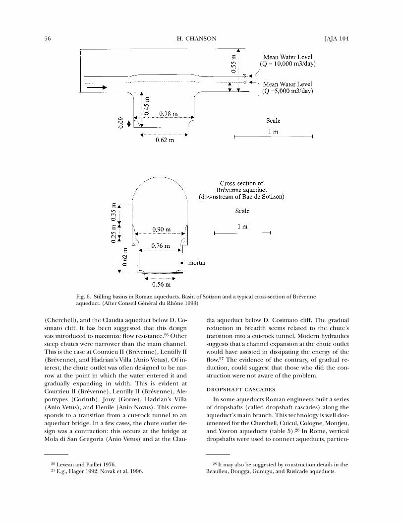
Stilling basins work best when the basin itself isdeep and long. The minimum length of modern hy-draulic jump stilling basins is about three to six timesthe downstream flow depth although, for oscillatinghydraulic jumps, the basin length must be longer: alength-to-depth ratio of about 6:1.24 At Sotizon thisratio is approximately 4:1. At Jouy it is approximately10:1, while at Oudna it is closer to 3.8:1, althoughthe basins at Oudna are circular in shape. Clearly,the Jouy basin had the most efficient design whilethat at Oudna was less than optimal. The circularshape of the Oudna basins, associated with a smallvolume, may have been intended to induce three-dimensional wave motion, associated with cross-waves,wave impact on the walls, and wave reflection.25 Con-sequently, a single basin would have been inade-quate for dampening wave propagation. There areat least five basins at Oudna, and this quantity mayrepresent an attempt by the Roman designers to ad-dress this problem.
Chute Geometry. In several instances, the design ofthe steep chutes differed from that of the main aque-duct channel. Some steep chutes were wider thanthe main channel, such as those at Chabet Ilelouine
22 Rakob (1979) commented on the frequent cleaningtask of the Carthage aqueduct basins. Lefebvre (1985) sim-ilarly mentioned the rate of sediment filling at Gorze.
23 At the start of Oued Miliane plain arcades.24 See, e.g., U.S. Department of the Interior 1960 and
Novak et al. 1996.25 A similar cross-wave pattern is experienced in undu-
lar hydraulic jumps and near-critical flows (Chanson andMontes 1995; Chanson 1995b).
Fig. 5. Sketch of different tailwater flow conditions andassociated backwater effects

2000] HYDRAULICS OF ROMAN AQUEDUCTS 55
Table 4. Tailwater Flow Conditions Downstream of Steep Chutes
(1) (2) (3)
Steep Section Q
(m3/day) Tailwater Flow Patterns
Brévenne aqueductCourzieu II/La Verrière 28,000 Undular jump 15.4 m d/s of change in slope
(dtw � 0.418 m)10,000 Undular jump 8.5 m d/s of change in slope
(dtw � 0.197 m)7,000 Undular jump 6.4 m d/s of change in slope
(dtw � 0.154 m)5,000 Undular jump 4.6 m d/s of change in slope
(dtw � 0.123 m)3,500 Undular jump 3.4 m d/s of change in slope
(dtw � 0.097 m)Chevinay/Plainet 28,000 Undular jump 13 m d/s of change in slope
(dtw � 0.434 m)10,000 Undular jump 7.2 m d/s of change in slope
(dtw � 0.204 m)7,000 Undular jump 5.4 m d/s of change in slope
(dtw � 0.154 m)5,000 Undular jump 3.8 m d/s of change in slope
(dtw � 0.127 m)3,500 Undular jump 2.8 m d/s of change in slope
(dtw � 0.10 m)Lentilly II/Les Molières-Montcher 28,000 Steady jump immediately d/s of change in slope
(dtw � 0.586 m)10,000 Oscillating jump 1.5 m d/s of change in slope
(dtw � 0.268 m)7,000 Oscillating jump 1.2 m d/s of change in slope
(dtw � 0.208 m)5,000 Oscillating jump 1 m d/s of change in slope
(dtw � 0.165 m)3,500 Oscillating jump 0.7 m d/s of change in slope
(dtw � 0.130 m)Gorze aqueduct 15,000 Undular flow in bridge-canal (Fr � 0.88); identical
flow pattern for operation with one and two canalsCarthage aqueduct
Oudna, start of Oued Miliane plain arcades
17,300 Undular flow d/s of change in slope: Fr � 0.7 (dtw ~ 0.228 m)
Corinth aqueductAlepotrypes 80,000 Plunging jet flow
Anio Vetus aqueductTivoli, Hadrian’s Villa 190,080 Steady jump at sudden enlargement (dtw ~ 1.7 m)Bridge at Mola di San Gregoria 190,080 Plunging jet flow (dtw ~ 1.8 m). Risk of undular flow in
d/s conduitClaudia aqueduct
below D. Cosimato cliff 190,900 Steady jump at change in slope (dtw ~ 2.2 m)Marcia aqueduct
Casale Acqua Raminga, Gericomio 188,000 Weak jump 9.1 m d/s of steep chute (dtw � 1.32 m)Anio Novus
near Torrente Fiumicino 190,080 Critical flow in downstream conduit (Fr � 1.03, dtw � 0.668 m)
Ponte dell’Inferno to Ponte Scalino
190,080 Subcritical backwater effect in steep chute associated with undular flow
Ponte Scalino to Ponte Amato 190,080 Plunging jet flow (dtw ~ 1.4 m). Risk of undular flow in d/s canal
Fienile 190,080 Plunging jet flow (dtw ~ 1.0 m). Risk of undular flow in d/s canal
dtw � tailwater normal depth; results based on backwater calculations (Chanson 1998); bold italic � unfavorable flow conditions.
56 H. CHANSON [AJA 104
(Cherchell), and the Claudia aqueduct below D. Co-simato cliff. It has been suggested that this designwas introduced to maximize flow resistance.26 Othersteep chutes were narrower than the main channel.This is the case at Courzieu II (Brévenne), Lentilly II(Brévenne), and Hadrian’s Villa (Anio Vetus). Of in-terest, the chute outlet was often designed to be nar-row at the point in which the water entered it andgradually expanding in width. This is evident atCourzieu II (Brévenne), Lentilly II (Brévenne), Ale-potrypes (Corinth), Jouy (Gorze), Hadrian’s Villa(Anio Vetus), and Fienile (Anio Novus). This corre-sponds to a transition from a cut-rock tunnel to anaqueduct bridge. In a few cases, the chute outlet de-sign was a contraction: this occurs at the bridge atMola di San Gregoria (Anio Vetus) and at the Clau-
dia aqueduct below D. Cosimato cliff. The gradualreduction in breadth seems related to the chute’stransition into a cut-rock tunnel. Modern hydraulicssuggests that a channel expansion at the chute outletwould have assisted in dissipating the energy of theflow.27 The evidence of the contrary, of gradual re-duction, could suggest that those who did the con-struction were not aware of the problem.
dropshaft cascadesIn some aqueducts Roman engineers built a series
of dropshafts (called dropshaft cascades) along theaqueduct’s main branch. This technology is well doc-umented for the Cherchell, Cuicul, Cologne, Montjeu,and Yzeron aqueducts (table 5).28 In Rome, verticaldropshafts were used to connect aqueducts, particu-
28 It may also be suggested by construction details in theBeaulieu, Dougga, Gunugu, and Rusicade aqueducts.
Fig. 6. Stilling basins in Roman aqueducts. Basin of Sotizon and a typical cross-section of Brévenneaqueduct. (After Conseil Général du Rhône 1993)
26 Leveau and Paillet 1976.27 E.g., Hager 1992; Novak et al. 1996.

2000] HYDRAULICS OF ROMAN AQUEDUCTS 57
larly from newer, higher channels to older canals.29
These shafts were sluice towers built primarily forwater redistribution. It is believed that the designwas probably a function of circumstances ratherthan a specific engineering feature of the neweraqueduct.
In modern hydraulics, there are at least three rec-
ognized purposes for designing dropshaft cascades.First, they may be used where the topography is espe-cially steep. This is clearly the case for the Romanaqueducts at Recret and Grézieu-la-Varenne, Yzeron;and at Montjeu and Autun (table 5, figs. 10–15).Until now it has been believed that dropshafts werebuilt to dissipate energy and possibly also, as dis-
29 At Grotte Sconce (also spelled Grotte Sconcie), abranch of the Anio Novus aqueduct led to a circular drop-shaft and into the Claudia aqueduct, and a second rectan-gular dropshaft led to the Marcia aqueduct (Ashby 1935,277–9 and fig. 31; Van Deman 1934, 212–3, 302–3). AtSan Cosimato Gorge, a side channel connected the Clau-dia to the Marcia aqueducts through a 9.2 m-deep rectan-
gular dropshaft (Ashby 1935, 101–2 and fig. 7; Van Deman1934, 76–7). Other examples of “interconnection shafts”included a square dropshaft from Claudia to Vetus atVoltata delle Corrozze (Van Deman 1934, 213) and a rect-angular shaft from Anio Novus to Claudia near the FossoArcese bridge (Ashby 1935, 275).
Fig. 7. Stilling basins in Roman aqueducts. Oudna, at the start of Oued Milianeplain arcades (Carthage aqueduct). (After Rakob 1974)

58 H. CHANSON [AJA 104
cussed above in the context of basins, to trap sedi-ment.30 Regardless of purpose, a dropshaft by designprovides a connection between two flat conduits, lo-cated at different elevations along the (usually short)length of the shaft. In contrast, a steep chute wouldrequire a much greater horizontal distance for thesame drop height. A second application of the drop-
shaft is the dissipation of the kinetic energy of theflow. Such a design is still used today.31 To work wellthis design must account for three factors: dropheight, shaft geometry, and flow rate. If these are notproperly considered, unacceptable scour and ero-sion may take place. A third application of the drop-shaft cascade is the aeration (or reoxygenation) of
Fig. 8. Stilling basins in Roman aqueducts. Jouy-aux-Arches downstream of theMoselle bridge-canal, Gorze aqueduct. (After Lefebvre 1996)
30 Conseil Général du Rhône 1991, 80; Gauckler 1902,129. Although there is some uncertainty whether theshafts at Hippo Zarite were dropshafts or inspection holes,
Gauckler (1902) mentioned specifically that the shafts weredesigned with an invert drop of 0.4 m to trap impurities.
31 E.g., Apelt 1984; Rajaratnam et al. 1997.

2000] HYDRAULICS OF ROMAN AQUEDUCTS 59
the flow. This occurs via air bubbles entrained byplunging jet action into the shaft pool.32
Hydraulics of Roman DropshaftsIn the Hydraulics Laboratory at the University of
Queensland, we investigated the hydraulics of theRoman dropshaft using a 1:4 scale model of the Rec-ret dropshaft on the Yzeron aqueduct (figs. 11, 16–17). The results33 highlighted several flow patternswith increasing flow rates. We expressed this in termsof dc/L, which is the ratio of critical flow depth (theheight of the drop, measured in meters) to the lengthof the dropshaft (also in meters).
At low flow rates (dc/L is less than or equal to0.15), the free-falling nappe (the water surface) im-pacts into the shaft pool; we categorize this scenarioas regime R1 (fig. 16). In this flow, substantial air-bubble entrainment occurs in the pool. In the down-stream channel, the flow is supercritical in the ab-sence of downstream backwater effect. In situationswhere the discharge rate is greater (the dc/L isgreater than 0.15 but less than 0.30), the uppernappe of the free-falling jet impacts into the down-stream channel, flowing in between the inlet invertand obvert; we categorize this as regime R2 (fig.17). In R2 the rate of energy dissipation is smaller,the pool free-surface level increases significantly,and less air-bubble entrainment is observed in thepool. At large flow rates (where dc/L is greaterthan or equal to 0.30), the free-jet impacts onto
the opposite wall, above the downstream conduitobvert (regime R3). The pool free-surface rises upto the downstream channel obvert, and the waterlevel in the pool fluctuates considerably. The thirdtype of regime, R3, common in modern dropshafts,occurs only at large flow rates and was unlikely inRoman aqueducts.
Dropshaft PerformanceThe analysis of the dropshaft-model performances
indicates that the optimum performances in termsof energy dissipation and flow aeration are achievedwith a flow regime such as that illustrated in R1 (fig.16). The experiments show that the flow regime R2is characterized by poor energy dissipation, littleflow aeration, and a high risk of scouring (figs. 17and 18). In flow regime R2, extensive damage wouldoccur very rapidly, typically in less than one day of op-eration. Most erosion would take place at the nappeimpact and at the downstream conduit intake (fig.18). The deterioration of modern concrete structuresis well documented,34 and worse damage would haveoccurred in Roman constructions. I suggest that, infact, the dropshafts had to be overdesigned in orderto prevent rapid and costly damage associated withthe regime R2, and that the aqueduct dropshaftshad to be built for an operation in a flow regime R1.
Table 6 summarizes the operation of well-docu-mented dropshafts based on analytical calculationsof the nappe trajectory and impact conditions.35 At
32 E.g., Ervine and Ahmed 1982; Chanson 1998.33 Chanson 1998.34 E.g., U.S. Department of the Interior 1965; Chanson
1995a, 198–201; Novak et al. 1996.
35 The calculations are based on the nappe trajectoryequation and shaft geometry (Chanson 1998). The resultswere validated successfully with the physical experiments.
Fig. 9. Sketch of stilling basin operation in Roman aqueduct

60 H. CHANSON [AJA 104
Table 5. Dropshaft Cascades in Roman Aqueducts
(1) (2) (3) (4) (5)Flow Conditions
Steep Section Ref. Geometry�H (m)
dc (m)
X (m) Remarks
Dougga aqueduct [Ca]Oued Melah B ~ 3.3 m
b ~ 0.35 m (tunnel)4 to 5 Located downstream of
200-m-long bridge, upstream of tunnel
Vaugneray, Yzeron aqueduct
[Co2] 21.9 Vaugneray branch of Yzeron aqueduct
Puit du Bourg Rectangular dropshaft: h � 2.55 m, b � 0.4 m, B � 1.14 m, L � 1.9 m
0.24 Downstream flow conditions: d ~ 0.35 m, V ~ 1.33 m/s
Recret/Grézieu-la-Varenne, Yzeron aqueduct
[Co2] Rectangular dropshafts 38 Main branch of Yzeron aqueduct
Puit Gouttenoire Square dropshaft: h � 2.55 m, b � 0.55 m, B � L � 1.18 m, P � 1.12 m
0.197
Puit-en-bas Rectangular dropshaft: h � 2.5 m, b � 0.55 m, B � L � 1.17 m, D � 1.26 m, P � 1.35 m
0.197 Downstream flow conditions: d ~ 0.15 m, V ~ 1.9 m/s
Chabet Ilelouine, Cherchell aqueduct
[LP] 12.28 4 series of steep chutes followed by circular dropshaft
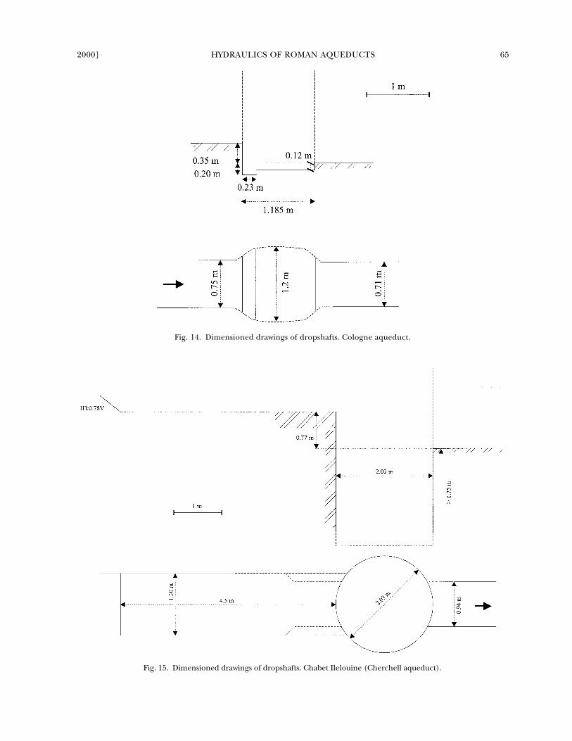
Puit amont Circular dropshaft: h � 0.77 m, b � 0.94 m,� � L � 2.03 m, P 1.75 m
Located downstream of steep smooth chute. Supercritical upstream flow: V ~ 8 m/s
Gunudu aqueduct 20Moulin Romain [LP] Circular dropshaft:
h ~ 3.5 to 4 m, b � 0.38 m, � � L � 0.80 m
Upstream channel: 0.86 m wide
Rusicade aqueduct [Ve] Circular dropshaftsBeaulieu aqueduct [CQ] 37 Combination of steep
chutes and dropshaftsPuit d’Olivari Dropshaft: h � 6.2 m,
b ~ 0.45 to 0.6 mRectangular or circular?
147 m between dropshafts
Puit du Château Dropshaft: h ~ 8 m Rectangular or circular? 167 m between dropshafts
Brisecou Forest, Montjeu aqueduct
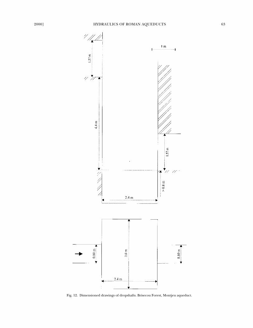
[CQ, PR] Rectangular dropshaft: h � 4.4 m, b � 0.8 m, B � 3.0 m, L � 2.4 m, D � 1.57 m, P 0.8 m
140 770 A series of 24 dropshafts (possible combination with steep chutes)
9 dropshafts (h � 4.4 m) 15 to 30 m between dropshafts
15 dropshafts (h � 4.4 m) 50 to 120 m between dropshafts
Cuicul aqueduct [Al]Grand thermae
distribution lineCircular (?) dropshafts: h ~ 1 to 0.4 m, b � 0.45 m, � � L � 0.80 m
3 85 Series of 4 dropshafts on an urban distribution line
Cologne aqueduct [Gr] Rectangular dropshaft: h � 0.35 m, b � 0.7 to 0.75 m, B � 0.9 m, L � 1.185 m, P � 0.2 m
Several dropshafts
dc: critical flow depth; X: dropshaft cascade length; �H: total head loss. References: [Al] Allais 1933; [Ca] Carton 1899; [Co2]Conseil Général du Rhône 1991; [CQ] Coquet 1966; [Gr] Grewe 1986; [LP] Leveau and Paillet 1976; [PR] Pinette and Re-bourg 1986; [Ve] Vertet 1983.

2000] HYDRAULICS OF ROMAN AQUEDUCTS 61
Cherchell, optimum performances (regime R1) wereachieved for discharges less than 6,600 m3/day.36
This result challenges the accepted maximum dis-charge of 40,000 m3/day.37 For the Yzeron aqueduct,optimum operation (i.e., regime R1) occurred forflow rates up to 7,500 m3/day in the Recret main sec-tion and 22,000 m3/day in the Vaugneray branch.The Montjeu aqueduct’s dropshafts at Brisecou For-est could operate safely with flow rates up to 40,400m3/day. It is reasonable to assume that the Recretbranch operated with a discharge less than 7,500 m3/day, a figure consistent with an overall discharge of10,000 to 13,000 m3/day in the Yzeron aqueduct, as-suming a flow rate of 5,000 m3/day at Vaugneray.38
However, it was unlikely that either the Vaugneraybranch or the Montjeu aqueduct operated at 22,000and 40,400 m3/day respectively. It is more likely that
these two series of dropshafts were oversized designsand that optimum operation of the dropshaft wasachieved in the setting outlined above as regime R1.39
chute and dropshaft designAlthough this study demonstrates the existence of
steep sections along the aqueducts, certain questionsremain. Were steep chutes and dropshafts inten-tional design features of Roman aqueducts? Did theaqueduct designer (librator) understand the basicconcepts of chute and dropshaft hydraulics? Indeed,it is plausible that some steep chutes were introducedas a functional solution to connect aqueduct sectionsthat had been built by different gangs.40 The con-struction of stilling basin and dropshaft was not (andis still not today) a simple job: it required the adviceof an experienced engineer.
36 The Cherchell dropshafts were preceded by steepchutes, and the inflow conditions of the shaft were torrential(supercritical). Chanson (1998, 4–16) developed a completeanalytical solution of the problem that gave a maximum flowrate of 6,600 m3/day (for optimum performances).
37 Leveau and Paillet 1976.38 For the Yzeron discharge, see Conseil Général du
Rhône 1991. Estimate of the Vaugneray branch flow rate isbased on the catchment in absence of further information.
39 In mathematical terms, for aqueducts equipped with
dropshafts operating with subcritical inflow, the flow ratemust satisfy:
Regime R1
where b is the dropshaft inflow width, L is the shaft length,and h is the invert drop (fig. 1) (Chanson 1998).
40 For the techniques of construction and the problemsassociated with connecting different sections, see Fevrier1979; Leveau 1979.
Q 0.1292 � g � b �L3
h3 2⁄----------<
Fig. 10. Dropshaft cascade in Roman aqueduct

62 H. CHANSON [AJA 104
Fig. 11. Dimensioned drawings of dropshafts. Recret Puit-en-bas, Yzeron aqueduct.
2000] HYDRAULICS OF ROMAN AQUEDUCTS 63
Fig. 12. Dimensioned drawings of dropshafts. Brisecou Forest, Montjeu aqueduct.

64 H. CHANSON [AJA 104
Fig. 13. Dimensioned drawings of dropshafts. Puit du Bourg, Vaugneray, Yzeron aqueduct (Vaugneray branch).
Well-documented evidence of aqueduct chutes andcascades clearly exists (tables 1–2, 5). These exam-ples suggest that those who built them knew the prob-lems they faced and intentionally designed the chutesand dropshafts accordingly. The series of steep chutesat Brévenne were imposed by the topography of thevalley. They included vertical drops of up to 87 m (i.e.,
Chevinay/Plainet), which could not have beenmerely a simple construction problem. These chuteswere part of the original design of the aqueducts. AtMontjeu, Yzeron, and Cherchell (figs. 12, 13, 15),large series of dropshafts were installed: 24 drop-shafts at Autun (
�
H
�
140 m), at least 15 dropshaftsat Recret and more at Vaugneray, and 4 dropshafts at
2000] HYDRAULICS OF ROMAN AQUEDUCTS 65
Fig. 14. Dimensioned drawings of dropshafts. Cologne aqueduct.
Fig. 15. Dimensioned drawings of dropshafts. Chabet Ilelouine (Cherchell aqueduct).

66 H. CHANSON [AJA 104
Chabet Ilelouine. Clearly these were engineering de-sign features of the aqueducts!
41
In both Roman andmodern times, the hydraulic design of chutes anddropshafts has been a highly specialized task; theengineering design of the Roman aqueduct wouldhave been reserved for only those Roman engi-neers with the highest skills. Nonetheless, there isno written documentation to support the theorythat the engineers understood the basic conceptsof continuity and energy as used in modern hydrau-lics. Even modern calculations of aqueduct hydraulicsare embryonic.
42
Table 7 summarizes those observations of very steepgradients that are well documented. Here we find evi-dence of very steep gradients in short stretches, up to78 percent at Chabet Ilelouine, Cherchell. Steepchutes were found across a wide geographic range inItaly, France, Algeria, and Turkey, suggesting that thesteep-gradient design was not unique to Rome butwas also employed at aqueducts elsewhere in the em-pire. Second, the steepest longitudinal slopes (notcounting stepped spillway chutes) were smooth andstepped chutes but not a series of dropshafts. Super-critical flow took place in steep channels. Most Roman
41
At Cuicul (Djemila, Algeria), the location of thedropshaft cascade was most unusual: it was on a distribu-tion branch in an urban environment rather than on themain line. The construction of the cascade was a majorcivil engineering work. Its underground location withinthe city might suggest that it was built prior to the sur-rounding buildings (e.g.,
thermae
) and that careful urbanplanning was done at Cuicul. Alternatively, the city expan-sion might have taken place in stages and the cascade
would have been out of town in an early stage.
42
The present study suggests that the current “misun-derstanding” of aqueduct hydraulics derives from the “ig-norance” of most historians and archaeologists. The hy-draulics calculations are easily feasible by undergraduateengineering students, provided that accurate informationon the channel dimensions and flow rate are available(Chanson 1999; Henderson 1966).
Fig. 16. Photograph of the Recret dropshaft model in op-eration. Regime R1, Q � 0.00104 m3/s, h/L � 1.68, D/L �0.83, dc/L � 0.0582. Side view. Flow from left to right.High-speed photograph (~ 50 �s).
Fig. 17. Photograph of the Recret dropshaft model in op-eration. Regime R2, Q � 0.00975 m3/s, h/L � 1.68, D/L �0.83, dc/L � 0.259. Side view, flow from left to right. High-speed photograph (~ 50 �s).

2000] HYDRAULICS OF ROMAN AQUEDUCTS 67
aqueducts had, overall, a mild slope that was associ-ated with subcritical flows. The transition from the“steep” chute flow to the subcritical flow was charac-terized by a hydraulic jump. Hence, Roman engi-neers clearly had some experience of both supercrit-ical flows and hydraulic jumps.
Third, and conversely, the data in table 7 high-lights the fact that series of dropshafts were not usedin the steepest topography, but rather for a range oflongitudinal mean slopes up to 20 percent (table7). This might suggest that dropshafts were notconsidered “safe” or “efficient” with very steep gra-dients. Construction problems may have affectedthe choice of dropshafts or steep chutes. Further,the dropshaft design might have been selected forpurposes other than energy dissipation alone; forexample, it might have been employed in somecases for re-aeration.
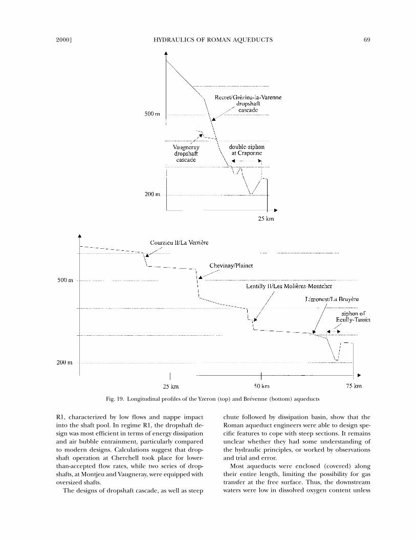
The Lyon aqueducts offer a useful example for acomparison between steep-chute and dropshaft cas-cade design. At Lyon, the Yzeron and Brévenne aque-ducts were both designed with steep longitudinalgradient sections (fig. 19).
43
The older of the two,the Yzeron aqueduct, was equipped with a series ofdropshafts (Recret, Vaugneray), while the aqueductat Brévenne was equipped with steep “smooth”chutes (e.g., Courzieu II, Chevinay, Lentilly II).
Why? At the Yzeron aqueduct, the overall drop ofthe two series of dropshafts was 38 m along 490 m atRecret, and 21.9 m along 375 m at Vaugneray, or7.8 percent and 5.8 percent, respectively. In com-parison, the overall gradient was about 4.8 to 5.4percent at Beaulieu and about 15 percent in aver-age at Montjeu (table 5).
These longitudinal gradients might seem smallcompared to the steep-chute gradients along theBrévenne aqueduct—22 percent at Courzieu II, 45percent at Chevinay, and 8.2 percent at Lentilly II(table 1)—but the intervals between the steepchutes varied from about 7 to 16 km (fig. 19)! Theoverall drop in elevation from one chute intake tothe next one was 65 m along 16.2 km at Courzieu II,140 m along 11.2 km at Chevinay, and 80 m along 7km at Lentilly II (0.4 percent, 1.25 percent, and 1.1percent, respectively).
In summary, these figures suggest that the seriesof dropshafts of the Yzeron aqueduct were used foran overall gradient of 6 to 8 percent, while, atBrévenne, the longitudinal gradient of the aqueductwas only about 0.4 to 1.25 percent, including thesteep chutes (fig. 19).
summary and conclusion
Roman aqueducts were equipped with short steepsections. For bed slopes ranging from 1 percent to78 percent, three types of designs were used: thesteep smooth chute followed occasionally by stillingbasin(s) (fig. 9), the stepped cascade, and the seriesof dropshafts (fig. 10).
Steep chute flows were characterized by high ve-locity supercritical flows. Tailwater conditions wereoften subcritical, and hydraulic jump flow conditionsoccurred at, or downstream of, the transition to theflat conduit. A complete backwater analysis has shownthe presence of unfavorable conditions associated withthese channels, in particular undular flows and oscillat-ing hydraulic jumps. I suggest that stilling basins weresometimes introduced to dissipate the energy of thewaters and to prevent downstream propagation ofsurge waves and undulations (fig. 9). These basinswere found at Alepotrypes, Courzieu II, Jouy, andOudna. This implies that Roman hydraulic engineersobserved flow instabilities along aqueducts and werecapable of introducing devices to dampen the effects.
In a 1:4 scale laboratory model of a Recret shaftbuilt specifically to investigate Roman dropshaft hy-draulics, I observed three flow regimes. Optimumdropshaft operation occurred for the flow regime
43
Burdy 1979, 64.
Fig. 18. Risks of scour and damage at a dropshaft opera-tion with a flow regime R2

68 H. CHANSON [AJA 104
Table 6. Summary of Aqueduct Dropshaft Operation
(1) (2) (3) (4)Aqueduct Flow Regime Flow Conditions Remarks
Cherchell
Chabet Ilelouine Regime R1 Q
�
6,600 m
3
/day Supercritical inflowRegime R2 Q
�
6,600 m
3
/day
Yzeron
Subcritical inflowsVaugneray Regime R1 Q
�
22,000 m
3
/dayRegime R2 22,000
�
Q
�
52,000 m
3
/dayRegime R3 Q
�
52,000 m
3
/day Assuming D
�
1.26 mPuit Gouttenoire Regime R1 Q
�
7,500 m
3
/dayRegime R2 7,500
�
Q
�
19,500 m
3
/dayRegime R3 Q
�
19,500 m
3
/day Assuming D
�
1.26 mPuit-en-bas Regime R1 Q
�
7,500 m
3
/dayRegime R2 7,500
�
Q
�
20,000 m
3
/dayRegime R3 Q
�
20,000 m
3
/day
Montjeu
Subcritical inflowsBrisecou Forest Regime R1 Q
�
40,400 m
3
/dayRegime R2 40,400
�
Q
�
74,700 m
3
/day
Regime R3
Q
�
74,700 m
3
/day
Table 7. Summary of Longitudinal Slopes of Steep Roman Chutes, Cascades, and Dropshaft Cascades
(1) (2) (3)
Steep Section Type Bottom Slope tan
(in %) Location
Aqueducts
Steep chute 1.1 Anio Novus (Ponte dell’Inferno to Ponte Scalino tunnel)Steep chute 1.3 Anio Novus (to Fienile tunnel)Steep chute 1.6 Anio Novus (Ponte Scalino to Ponte Amato tunnel)Steep chute 3.0 Corinth (Alepotrypes, upstream of stilling basin)Dropshaft 4.1 Beaulieu (Puit d’Olivari)Dropshaft (circ.) 4.8 Beaulieu (Puit du Château)Dropshaft (circ.) 5.1 Cuicul (Series of 4 dropshafts along thermae, distribution line)Dropshafts 5.2 Montjeu, Autun (series of 24 dropshafts)Dropshafts (rect.) 5.8 Yzeron (Vaugneray, Puit du Bourg)Steep chute 6.1 Anio Novus (Torrente Fiumicino)Dropshafts (sq.) 7.8 Yzeron (Recret/Grézieu-la-Varenne cascade)Steep chute 8.3 Brévenne (Lentilly II/Les Molières-Montcher)Steep chute 10.7 Marcia (Gericomio)Steep chute 15.7 Marcia (Gericomio)Steep chute 16.4 Anio Vetus (Bridge at Mola di San Gregoria)Drops or chutes? 19.0 Brévenne (Lentilly II - Le Guéret-La Rivoire)Dropshafts (rect.) 19.6 Montjeu, Autun (9 dropshafts)Drops or chutes? 20.0 Brévenne (St.-Pierre-La-Palud I)Steep chute 20.6 Anio Vetus (Tivoli, Hadrian’s Villa)Steep chute 22 Brévenne (Courzieu II/La Verrière)Steep chute 45 Brévenne (Chevinay/Plainet)Steep chute 50 Claudia (below D. Cosimato cliff, upstream of bridge
below Vicavaro)Stepped chute 61 Andriake, LyciaSteep chutes 78 Cherchell, Chabet Ilelouine
Dropshafts
chutes 38.4 Cherchell, Chabet Ilelouine (combination of dropshafts and chutes)
Spillways
Stepped chute 122 to 164 Oued Guergour damStepped chute 167 Oued Bou Mazouz dam
Stepped chute
229
Kasserine dam
2000] HYDRAULICS OF ROMAN AQUEDUCTS 69
Fig. 19. Longitudinal profiles of the Yzeron (top) and Brévenne (bottom) aqueducts
R1, characterized by low flows and nappe impactinto the shaft pool. In regime R1, the dropshaft de-sign was most efficient in terms of energy dissipationand air bubble entrainment, particularly comparedto modern designs. Calculations suggest that drop-shaft operation at Cherchell took place for lower-than-accepted flow rates, while two series of drop-shafts, at Montjeu and Vaugneray, were equipped withoversized shafts.
The designs of dropshaft cascade, as well as steep
chute followed by dissipation basin, show that theRoman aqueduct engineers were able to design spe-cific features to cope with steep sections. It remainsunclear whether they had some understanding ofthe hydraulic principles, or worked by observationsand trial and error.
Most aqueducts were enclosed (covered) alongtheir entire length, limiting the possibility for gastransfer at the free surface. Thus, the downstreamwaters were low in dissolved oxygen content unless
70 H. CHANSON [AJA 104
reoxygenation devices were installed. I suggest thatdropshafts may have been introduced in place ofsteep chutes in order to reoxygenate the water aswell as to dissipate the energy of the flow. Aerationtechnology is commonly used today to reoxygenatedepleted waters and to enhance the water quality. Irecommend that further archaeological work focuson the excavation and survey of chutes and drop-shafts to confirm this hypothesis.
hydraulics and environmental engineering
department of civil engineeringthe university of queenslandbrisbane qld 4072australiah.chanson
@
mailbox.uq.edu.au
Appendix
hydraulics of open channel flow: definitions and basic equations
In open channel flows (e.g., fig. 1, a smooth chute),the
critical depth
d
c
is the depth of flow producingmaximum flow rate for a given specific energy. For arectangular channel it equals: where Q isthe discharge, g is the gravity acceleration, and b isthe channel breadth. If the flow is critical, smallchanges in specific energy cause very large changesin depth. In practice, critical flows over a long reachof channel are unstable, characterized by large free-surface undulations. Such a flow pattern, called un-dular flow, is experienced with
near-critical
flowscharacterized by a Froude number greater than 0.3but less than 3.0; where , V is the flowvelocity and d is the flow depth.
44
Subcritical, or tranquil, flow occurs when the flowdepth (d) is greater than the critical depth. As achannel becomes steeper, water tends to flow withgreater velocity and shallower depth until, on steepsections, supercritical flow occurs and the rapid flowdepth is less than the critical depth. Subcritical andsupercritical flows are also called fluvial and torren-tial flows, respectively.
The transition back from supercritical to subcriti-cal flow conditions creates a hydraulic jump, wherethe depth of flow suddenly increases. A hydraulic
Q2/gb23
Fr V/ gd=
jump is undesirable because it leads to flow instabil-ity and possible surges, and thus has great erosive po-tential. Experimental observations highlighted dif-ferent types of hydraulic jumps, depending upon theFroude number of the upstream flow. An undularhydraulic jump is observed at low Froude numbers(between 1 and 3). With increasing Froude num-bers, other types of jumps include weak jump, oscil-lating jump (Froude number between 3.5 and 4.5),steady jump, and strong jump (Froude number isgreater than or equal to 10) (see, e.g., fig. 4).
45
hydraulic calculations of steep chutes and cascades
In long prismatic chutes, the flow conditions insteep chutes may be calculated assuming uniformequilibrium flow conditions (i.e., normal flow):
where V
o
is the uniform equilibrium flow velocity,(D
H
)
o
is the hydraulic diameter
46
at uniform equilib-rium, f is the Darcy-Weisbach friction factor, and
is the channel slope (fig. 1). The friction factor f isestimated from the Moody diagram for smoothchutes.
47
I computed f to be between 0.02 and 0.04for Roman aqueducts with smooth mortar lining.For skimming flow over stepped cascades, f increasesfrom 0.1 to 1 for bed slopes from 5 to 10 degrees,and f equals about 1 for steeper slopes.
48
There is a fundamental difference between smoothand stepped chutes: the kinetic energy of the flow issignificantly larger in smooth chute flow than for astepped one, for identical flow rate and chute prop-erties. As a result, larger energy dissipation must takeplace at the end of a smooth canal, and sometimesstilling structures must be introduced.
list of symbols
A cross-section area (m
2
)B dropshaft width (m)b open channel width (m)D conduit height (m)DH hydraulic diameter (m), or equivalent pipe di-
ameter, defined as:
Vo
8gf---------
DH( )o4--------------------- sin θ=
DH 4cross tionalsec– area
wetted perimeter--------------------------------------------------------- 4A
Pw-------= =� �( )
44 For near-critical flows, see Chanson 1995b. In rectan-gular flat channels, the Froude number is unity at criticalflow conditions: i.e., Fr � 1 for d � dc (critical flow depth).
45 This classification is valid only for hydraulic jumps inrectangular horizontal channels (e.g., Henderson 1966;Chanson 1999).
46 The hydraulic diameter is defined as four times thecross-section area (of the flow) divided by the wetter pe-rimeter: DH � 4(A/Pw).
47 Moody 1944.48 Chanson 1995a, 87–8.

2000] HYDRAULICS OF ROMAN AQUEDUCTS 71
d flow depth (m) measured perpendicular to thechannel bed
db brink depth (m): i.e., depth at the edge of a dropdc critical flow depth (m); in a rectangular channel:
do uniform equilibrium flow depth (m): i.e., nor-mal depth
dtw tailwater flow depth (m)f Darcy friction factor (also called head loss co-
efficient)Fr Froude number; for a rectangular channel:
Fr � � g gravity constant (m/s2)H total head (m)h 1 – step height (m)
2 – invert drop (m) at a vertical dropshaftL 1 – dropshaft length (m)
2 – length (m) of stilling basinl step length (m)P (shaft) pool height (m), measured from the
shaft bottom to the downstream conduit invertPw wetted perimeter (m)Q total volume discharge (m3/s) of waterq discharge per meter width (m2/s); for a rectan-
gular channel: q � Q/bV flow velocity (m/s); Vb brink flow velocity (m/s)Vo uniform equilibrium flow velocity (m/s)X chute/cascade length (m)x horizontal Cartesian coordinate (m)y vertical Cartesian coordinate (m)
Greek Symbols�H head loss (m): i.e., change in total head�z change in bed (invert) elevation (m) bed (invert) slope� diameter (m)
Subscriptc critical flow conditions� uniform equilibrium flow conditions� tailwater flow conditions
AbbreviationsD/S (or d/s) downstreamU/S (or u/s) upstream
Works Cited
Allais, Y. 1933. “L’Alimentation en eau d’une ville ro-maine d’Afrique: Cuicul (Djemila).” Cinquième congrèsinternational d’archéologie, Alger, 14–16 avril 1930, 93–117. Algiers: Société historique algérienne.
Apelt, C.J. 1984. “Goonyella Railway Duplication DropStructures and Energy Dissipators at Culvert Outlets:Model Studies.” Report CH27/84, Dept. of Civil Engi-neering, University of Queensland.
dc �3√ q2/g
V/√ gd Q/√ gd3 b2
Ashby, T. 1935. The Aqueducts of Ancient Rome. Edited byI.A. Richmond. Oxford: Clarendon.
Blackman, D.R. 1978. “The Hydraulics of Aqueducts atRome: A Study of the Four Great Aqueducts.” MMELReport No. 35, Dept. of Mechanical Engineering,Monash University, Australia.
–––––. 1979. “The Length of the Four Great Aqueductsof Rome.” BSR 47:12–8.
Bradley, J.N., and A.J. Peterka. 1957a. “The HydraulicDesign of Stilling Basins: Hydraulic Jumps on a Hori-zontal Apron (Basin 1).” Journal of the Hydraulic Divi-sion 83/HY5:1401-1/1401-22.
–––––. 1957b. “The Hydraulic Design of Stilling Basins:Stilling Basin and Wave Suppressors for Canal Struc-tures, Outlet Works, and Diversion Dams (Basin 4).”Journal of the Hydraulic Division 83/HY5:1404-1/1404-20.
Burdy, J. 1979. “Lyon: Lugudunum et ses quatre aque-ducs.” Dossiers de l’archéologie, Séries les aqueducs romains38:62–73.
–––––. 1996. Lyon: L’aqueduc romain du Gier. Préinven-taire des monuments et richesses artistiques 4. Lyon:Conseil Général du Rhône.
Carton, L.B.C. 1899. “Notices sur les fouilles exécutéesà Dougga.” Bulletin trimestriel de géographie et d’archéolo-gie de la S.G.A.P.O. 13:157–9.
Chanson, H. 1995a. Hydraulic Design of Stepped Cascades,Channels, Weirs, and Spillways. Oxford: Pergamon.
–––––. 1995b. “Flow Characteristics of Undular Hydrau-lic Jumps: Comparison with Near-critical Flows.” Re-port CH45/95, Dept. of Civil Engineering, Universityof Queensland.
–––––. 1997. “A Short History of Stepped Cascades inAustralia.” ANCOLD Bulletin 106:101–11.
–––––. 1998. The Hydraulics of Roman Aqueducts: SteepChutes, Cascades, and Dropshafts. Brisbane: Universityof Queensland.
–––––. 1999. The Hydraulics of Open Channel Flows: An In-troduction. London: John Wiley and Sons.
Chanson, H., and J.S. Montes. 1995. “Characteristics ofUndular Hydraulic Jumps: Experimental Apparatusand Flow Patterns.” Journal of Hydraulic Engineering121:129–44 and 123:161–4.
Clamagirand, E., S. Rais, J. Chahed, R. Guefrej, and L.Smaoui. 1990. “L’Aqueduc de Carthage.” Journal LaHouille Blanche 6:423–31.
Conseil Général du Rhône. 1987. L’Aqueduc romain duMont d’Or. Edited by H. Hours. Préinventaire desmonuments et richesses artistiques 1. Lyon: ConseilGénéral du Rhône.
Conseil Général du Rhône. 1991. L’Aqueduc romain del’Yzeron. Edited by H. Hours. Préinventaire des mon-uments et richesses artistiques 2. Lyon: ConseilGénéral du Rhône.
Conseil Général du Rhône. 1993. L’Aqueduc romain de laBrévenne. Edited by H. Hours. Préinventaire des mon-uments et richesses artistiques 3. Lyon: ConseilGénéral du Rhône.
Coquet, M. 1966. “Les aqueducs romains de Beaulieu etles puits de rupture de pente.” Cahiers ligures de préhis-toire et d’archéologie 15:283–95.

72 H. CHANSON, HYDRAULICS OF ROMAN AQUEDUCTS
Darcy, H.P.G., and H. Bazin. 1865. Recherches hy-drauliques. Paris: Imprimerie nationale.
Ervine, D.A., and A.A. Ahmed. 1982. “A Scaling Rela-tionship for a Two-dimensional Vertical Dropshaft.”In Proceedings of the International Conference on Hydrau-lic Modelling of Civil Engineering Structures, 195–214.Coventry: British Hydromechanics Research Associa-tion Fluid Engineering.
Fabre, G., J.L. Fiches, P. Leveau, and J.L. Paillet. 1992.The Pont du Gard: Water and the Roman Town. Paris:Presses du CNRS.
Fair, G.M., J.C. Geyer, and D.A. Okun. 1971. Elements ofWater Supply and Wastewater Disposal. 2nd ed. NewYork: Wiley.
Fevrier, P.A. 1979. “L’Armée romaine et la constructiondes aqueducs.” Dossiers de l’archéologie, Séries les aque-ducs romains 38:88–93.
François, J., and N. Tabouillot. [1769] 1974. “Histoirede Metz par les religieux bénédictins de la congréga-tion de Saint-Vanne.” Imprimerie Claude-Sigisbert La-mort 1:130–51. Reprint, Paris.
Gauckler, P. 1897. Enquête sur les installations hydrauliquesromaines en Tunisie 1. Tunis: Imprimerie rapide.
–––––. 1902. Enquête sur les installations hydrauliques ro-maines en Tunisie 2. Tunis: Imprimerie rapide.
Gauckler, P.G. 1867. “Etudes théoriques et pratiques surl’ecoulement et le mouvement des eaux.” Comptesrendues de l’académie des sciences 64:818–22.
Grewe, K. 1986. Atlas der römischen Wasserleitungen nachKöln. Cologne: Rheinland-Verlag.
Hager, W.H. 1992. Energy Dissipators and HydraulicJump. Kluwer Academic Publications, Water Sci-ence and Technology Library 8. Dordrecht: KluwerAcademic.
Henderson, F.M. 1966. Open Channel Flow. New York:MacMillan College Division.
Hodge, A.T. 1992. Roman Aqueducts and Water Supply.London: Duckworth.
Knauss, J. 1995. “ΤΗΣ ΓΡΙAΣ TO ΠH∆HMA, der Alt-weibersprung: Die Rätselhafte Alte Talsperre in derGlosses-Schlucht bei Alyzeia in Akarnanien.” AA5:137–62.
Lefebvre, C. 1985. “L’Aqueduc romain de Gorze àMetz: Etat de recherche.” Cahiers lorrains 1:21–51.
–––––, ed. 1996. L’Aqueduc antique de Gorze à Metz.Nancy: Serpenoise.
Leveau, P. 1979. “La construction des aqueducs.” Dos-siers de l’archéologie, Séries les aqueducs romains 38:8–19.
–––––. 1991. “Research on Roman Aqueducts in thePast Ten Years.” In Future Currents in Aqueduct Studies,edited by T. Hodge, 149–62. Leeds: F. Cairns.
Leveau, P., and J.L. Paillet. 1976. L’Alimentation en eau deCaesarea de Maurétanie et l’aqueduc de Cherchell. Paris:Éditions l’Harmattan.
Lolos, Y.A. 1997. “The Hadrianic Aqueduct of Corinth(with an Appendix on the Roman Aqueducts inGreece).” Hesperia 66:271–314.
Montes, J.S., and H. Chanson. 1998. “Characteristics ofUndular Hydraulic Jumps: Results and Calculations.”Journal of Hydraulic Engineering 124:192–205.
Moody, L.F. 1944. “Friction Factors for Pipe Flow.”Transactions of the American Society of Mechanical Engi-neers 66:671–84.
Novak, P., A.I.B. Moffat, C. Nalluri, et al. 1996. HydraulicStructures. 2nd ed. London.
Ortloff, C.R., and D.P. Crouch. 1998. “Hydraulic Analy-sis of a Self-cleaning Drainage Outlet at the Hellenis-tic city of Priene.” Journal of Archaeological Science25:1211–20.
Pinette, M., and A. Rebourg. 1986. Autun (Saône-et-Loire):Ville Gallo-Romaine. Paris: Imprimerie nationale.
Rajaratnam, N., A. Mainali, and C.Y. Hsung. 1997. “Ob-servations on Flow in Vertical Dropshafts in UrbanDrainage Systems.” Journal of Environmental Engineer-ing 123:486–91.
Rakob, F. 1974. “Das Quellenheiligtum in Zaghouanund die Römische Wasserleitung nach Karthago.”MDI-RA 81:41–89, pls. 21–76 and maps.
–––––. 1979. “L’Aqueduc de Carthage.” Dossiers del’archéologie, Séries les aqueducs romains 38:34–42.
U.S. Department of the Interior. 1960. Design of SmallDams. Denver: U.S. Government Printing Office.
Van Deman, E.B. 1934. The Building of the Roman Aque-ducts. Washington, D.C.: Carnegie Institution.
Vertet, H. 1983. “Observations sur les aqueducs de Rusicade(Algérie).” In Journées d’étude sur les aqueducs romains,Lyon, 26–28 mai 1977, 349–69. Paris: Les Belles Lettres.